EP2778528A2 - Gas flow control device for gas stove and gas stove - Google Patents
Gas flow control device for gas stove and gas stove Download PDFInfo
- Publication number
- EP2778528A2 EP2778528A2 EP14157907.8A EP14157907A EP2778528A2 EP 2778528 A2 EP2778528 A2 EP 2778528A2 EP 14157907 A EP14157907 A EP 14157907A EP 2778528 A2 EP2778528 A2 EP 2778528A2
- Authority
- EP
- European Patent Office
- Prior art keywords
- gas
- flow control
- control device
- rotating portion
- spool
- Prior art date
- Legal status (The legal status is an assumption and is not a legal conclusion. Google has not performed a legal analysis and makes no representation as to the accuracy of the status listed.)
- Granted
Links
Images


Classifications
-
- F—MECHANICAL ENGINEERING; LIGHTING; HEATING; WEAPONS; BLASTING
- F23—COMBUSTION APPARATUS; COMBUSTION PROCESSES
- F23N—REGULATING OR CONTROLLING COMBUSTION
- F23N1/00—Regulating fuel supply
- F23N1/005—Regulating fuel supply using electrical or electromechanical means
-
- F—MECHANICAL ENGINEERING; LIGHTING; HEATING; WEAPONS; BLASTING
- F16—ENGINEERING ELEMENTS AND UNITS; GENERAL MEASURES FOR PRODUCING AND MAINTAINING EFFECTIVE FUNCTIONING OF MACHINES OR INSTALLATIONS; THERMAL INSULATION IN GENERAL
- F16K—VALVES; TAPS; COCKS; ACTUATING-FLOATS; DEVICES FOR VENTING OR AERATING
- F16K11/00—Multiple-way valves, e.g. mixing valves; Pipe fittings incorporating such valves
- F16K11/10—Multiple-way valves, e.g. mixing valves; Pipe fittings incorporating such valves with two or more closure members not moving as a unit
- F16K11/14—Multiple-way valves, e.g. mixing valves; Pipe fittings incorporating such valves with two or more closure members not moving as a unit operated by one actuating member, e.g. a handle
-
- F—MECHANICAL ENGINEERING; LIGHTING; HEATING; WEAPONS; BLASTING
- F16—ENGINEERING ELEMENTS AND UNITS; GENERAL MEASURES FOR PRODUCING AND MAINTAINING EFFECTIVE FUNCTIONING OF MACHINES OR INSTALLATIONS; THERMAL INSULATION IN GENERAL
- F16K—VALVES; TAPS; COCKS; ACTUATING-FLOATS; DEVICES FOR VENTING OR AERATING
- F16K31/00—Actuating devices; Operating means; Releasing devices
- F16K31/02—Actuating devices; Operating means; Releasing devices electric; magnetic
- F16K31/04—Actuating devices; Operating means; Releasing devices electric; magnetic using a motor
- F16K31/047—Actuating devices; Operating means; Releasing devices electric; magnetic using a motor characterised by mechanical means between the motor and the valve, e.g. lost motion means reducing backlash, clutches, brakes or return means
-
- F—MECHANICAL ENGINEERING; LIGHTING; HEATING; WEAPONS; BLASTING
- F16—ENGINEERING ELEMENTS AND UNITS; GENERAL MEASURES FOR PRODUCING AND MAINTAINING EFFECTIVE FUNCTIONING OF MACHINES OR INSTALLATIONS; THERMAL INSULATION IN GENERAL
- F16K—VALVES; TAPS; COCKS; ACTUATING-FLOATS; DEVICES FOR VENTING OR AERATING
- F16K31/00—Actuating devices; Operating means; Releasing devices
- F16K31/44—Mechanical actuating means
- F16K31/52—Mechanical actuating means with crank, eccentric, or cam
- F16K31/524—Mechanical actuating means with crank, eccentric, or cam with a cam
- F16K31/52408—Mechanical actuating means with crank, eccentric, or cam with a cam comprising a lift valve
- F16K31/52416—Mechanical actuating means with crank, eccentric, or cam with a cam comprising a lift valve comprising a multiple-way lift valve
-
- F—MECHANICAL ENGINEERING; LIGHTING; HEATING; WEAPONS; BLASTING
- F24—HEATING; RANGES; VENTILATING
- F24C—DOMESTIC STOVES OR RANGES ; DETAILS OF DOMESTIC STOVES OR RANGES, OF GENERAL APPLICATION
- F24C3/00—Stoves or ranges for gaseous fuels
- F24C3/12—Arrangement or mounting of control or safety devices
-
- F—MECHANICAL ENGINEERING; LIGHTING; HEATING; WEAPONS; BLASTING
- F23—COMBUSTION APPARATUS; COMBUSTION PROCESSES
- F23K—FEEDING FUEL TO COMBUSTION APPARATUS
- F23K2900/00—Special features of, or arrangements for fuel supplies
- F23K2900/05002—Valves for gaseous fuel supply lines
-
- F—MECHANICAL ENGINEERING; LIGHTING; HEATING; WEAPONS; BLASTING
- F23—COMBUSTION APPARATUS; COMBUSTION PROCESSES
- F23N—REGULATING OR CONTROLLING COMBUSTION
- F23N2235/00—Valves, nozzles or pumps
- F23N2235/12—Fuel valves
- F23N2235/14—Fuel valves electromagnetically operated
-
- F—MECHANICAL ENGINEERING; LIGHTING; HEATING; WEAPONS; BLASTING
- F23—COMBUSTION APPARATUS; COMBUSTION PROCESSES
- F23N—REGULATING OR CONTROLLING COMBUSTION
- F23N2235/00—Valves, nozzles or pumps
- F23N2235/12—Fuel valves
- F23N2235/18—Groups of two or more valves
-
- F—MECHANICAL ENGINEERING; LIGHTING; HEATING; WEAPONS; BLASTING
- F23—COMBUSTION APPARATUS; COMBUSTION PROCESSES
- F23N—REGULATING OR CONTROLLING COMBUSTION
- F23N2235/00—Valves, nozzles or pumps
- F23N2235/12—Fuel valves
- F23N2235/24—Valve details
Definitions
- the present invention relates to the field of gas stoves, and more particularly to the field of gas flow control technologies of gas stoves.
- a gas stove generally uses a stopcock, and a structure of a typical stopcock is shown in FIG. 1 .
- the volume of the stopcock is small, so that the number of holes provided on a spool is limited, which limits the number of levels. It can be said that the foregoing technical problem severely restricts the development of the gas stove.
- the main objective of the present invention is to provide a novel gas flow control device for a gas stove and a gas stove to solve the foregoing problem.
- a gas flow control device for a gas stove includes a drive device, a valve body, a rotating portion, a reposition device, and a spool;
- the valve body includes an inner cavity, a gas inlet, and a gas outlet, and the gas inlet and the gas outlet are separately in communication with the inner cavity;
- the spool is disposed in the inner cavity;
- the drive device is used to drive the rotating portion to rotate; when the rotating portion is located in a first rotation position, the spool, under the action of the rotating portion, closes the gas outlet; and when the rotating portion is located in a second rotation position, the spool, under the action of the reposition device, opens the gas outlet.
- the present invention provides a whole new gas flow control scheme for a gas stove. By adopting the technical solution, the number of levels of the gas stove can be easily increased.
- the spool when the rotating portion is located in the first rotation position, the spool is pushed or pulled by the rotating portion to close the gas outlet; and when the rotating portion is located in the second rotation position, the spool is pushed or pulled by the reposition device to open the gas outlet.
- the reposition device includes a spring.
- the spool is provided with a mounting slot, and one end of the spring is placed in the mounting slot.
- the other end of the spring is pressed against a wall defining the inner cavity.
- valve body is of a composite structure.
- he valve body further includes a replaceable flow adjustment member; and the gas outlet is disposed on the flow adjustment member.
- the gas flow control device may use a flow adjustment member provided with a gas outlet with a different inner diameter, so that the gas flow control device can be compatible with different gas sources.
- the gas flow control device further includes a flow adjustment screw used to adjust the flow of gas flowing out from the gas outlet.
- the drive device includes a motor and a shaft, and the motor is used to drive the shaft to rotate; and the shaft is connected to the rotating portion, and the shaft is used to drive the rotating portion to rotate.
- the rotating portion includes a cam
- the spool includes a pressing portion
- the pressing portion is pressed against a cam surface of the cam
- the cam surface includes a first surface area and a second surface area
- the pressing portion is pressed against the second surface area.
- a cross-section of the cam is of a circular structure having a notch; the first surface area corresponds to an arc of the circular structure; the second surface area corresponds to the notch of the circular structure; and the cam rotates about the center of the circle of the circular structure.
- the number of the cams is at least 2; each cam corresponds to a gas outlet, a reposition device, and a spool; and the shaft runs through the centers of the circles of the circular structures corresponding to the cams successively.
- the number of the gas outlets is at least two; and each gas outlet corresponds to a rotating portion, a reposition device, and a spool.
- the gas outlets include at least two first gas outlets and at least two second gas outlets; the first gas outlets together supply gas to an inner-ring fire cover; and the second gas outlets together supply gas to an outer-ring fire cover.
- each spool corresponds to an inner cavity; and each inner cavity corresponds to a gas inlet.
- the present invention further provides a gas flow control device for a gas stove, which includes a drive device, a valve body, a rotating portion, a reposition device, and a spool;
- the valve body includes an inner cavity, a gas inlet, and a gas outlet, and the gas inlet and the gas outlet are separately in communication with the inner cavity;
- the spool is disposed in the inner cavity;
- the drive device is used to drive the rotating portions to rotate; when the rotating portion is located in a third rotation position, the spool, under the action of the rotating portion, opens the gas outlet; and when the rotating portion is located in a fourth rotation position, the spool, under the action of the reposition device, closes the gas outlet.
- the present invention provides a whole new gas flow control scheme for a gas stove. By adopting the technical solution, the number of levels of the gas stove can be easily increased.
- the spool when the rotating portion is located in the third rotation position, the spool is pushed or pulled by the rotating portion to open the gas outlet; and when the rotating portion is located in the fourth rotation position, the spool is pushed or pulled by the reposition device to close the gas outlet.
- the present invention further provides a gas stove, which is provided with the gas flow control device described above.
- the present invention provides a whole new gas flow control scheme for a gas stove. By adopting the technical solution, the number of levels of the gas stove can be easily increased.
- FIG. 2 is only an exploded view of a local structure of the gas flow control device, and in order to clearly show an internal structure, the gas flow control device is cut.
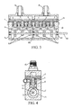
- FIG. 3 and FIG. 5 are sectional views obtained by cutting along a length direction of the gas flow control device;
- FIG. 4 and FIG. 6 are sectional views obtained by cutting along a width direction of the gas flow control device.
- the gas flow control device for a gas stove includes a drive device, a valve body 1, six rotating portions, six springs 3, and six spools.
- the six rotating portions correspond to and fit the six spools respectively
- the six springs 3 correspond to and fit the six spools respectively.
- the valve body 1 includes six inner cavities 6, a replaceable flow adjustment member 11, six gas inlets 7, and six gas outlets.
- the six gas outlets are all disposed on the flow adjustment member 11, and the six gas outlets all run through the flow adjustment member 11 in a thickness direction of the flow adjustment member 11.
- the six gas inlets 7 correspond to the six inner cavities 6 respectively, and each gas inlet 7 is in communication with the inner cavity 6 corresponding to the gas inlet 7.
- the six gas outlets correspond to the six inner cavities 6 respectively, and each gas outlet is in communication with the inner cavity 6 corresponding to the gas outlet.
- a gas supply pipe is used to supply gas to the six gas inlets 7, and as shown in FIG.
- the gas supply pipe is provided with six gas delivery ports corresponding to the six gas inlets 7 respectively, and each gas delivery port is used to supply gas to the gas inlet 7 corresponding to the gas delivery port.
- the six inner cavities 6 correspond to and fit the six spools respectively. Each spool is disposed in the inner cavity 6 corresponding to the spool.
- the spool includes a spool upper portion 4 and a spool lower portion 5.
- the spool lower portion 5 is provided with a mounting slot 10, and one end of the spring 3 is placed in the mounting slot 10. The other end of the spring 3 is pressed against a wall defining the inner cavity 6, and in this embodiment, the other end of the spring 3 is pressed against the flow adjustment member 11.
- the drive device is used to drive the rotating portions to rotate.
- the drive device includes a motor (not shown) and a shaft 12, the shaft 12 is of an elongated cylindrical structure, and the motor is used to drive the shaft 12 to rotate about the axis of the shaft.
- the six rotating portions are all cams 2.
- the shaft 12 runs through the six cams 2 successively along thickness directions of the six cams 2 respectively, and the shaft 12 is connected to and fixed together with the six cams 2.
- the motor is a stepper motor.
- the spool includes a pressing portion 13, and the pressing portion 13 is pressed against a cam surface of the cam 2.
- the cam surface includes a first surface area 14 and a second surface area 15.
- a cross-section of the cam 2 is of a circular structure having a notch, the shaft 12 is located at the center of the circular structure; the first surface area 14 corresponds to an arc of the circular structure; the second surface area 15 corresponds to the notch of the circular structure.
- a transition surface is disposed between the first surface area 14 and the second surface area 15.
- the six gas outlets include three first gas outlets 8 and three second gas outlets 9.
- the three first gas outlets 8 together supply gas to an inner-ring fire cover.
- the three second gas outlets 9 together supply gas to an outer-ring fire cover.
- the three first gas outlets 8 are the first to third gas outlets counted from the left in the drawings
- the three second gas outlets 9 are the fourth to sixth gas outlets counted from the left in the drawings.
- the gas can flow into the inner cavities 6 only through the gas inlets 7, and the gas that flows into the inner cavities 6 can flow out only through the first gas outlets 8 and/or the second gas outlets 9.
- Each cam 2 correspondingly has a "first rotation position". For each cam 2 located in the first rotation position thereof, the spool corresponding to the cam 2 is pushed by the cam 2 to close the corresponding gas outlet; at the moment, the spring 3 corresponding to the cam 2 is in a compressed state. It should be noted here that, although each cam 2 correspondingly has the “first rotation position”, it does not mean that "first rotation positions” corresponding to any two cams 2 are necessarily the same, and in fact, the first rotation positions may be the same, or different, or partially the same. Further, the "first rotation position" may be a position point, and may also be a rotation amplitude formed by a series of successively connected position points. As shown in FIG.
- each cam 2 in FIG. 3 is located in the first rotation position thereof, and no gas flows to the inner-ring fire cover or the outer-ring fire cover.
- the second to sixth cams 2 counted from the left in FIG. 5 are each located in the first rotation positions thereof.
- Each cam 2 correspondingly has a "second rotation position". For each cam 2 located in the second rotation position, the spool corresponding to the cam 2 is pushed by the spring 3 to open the gas outlet; at the moment, the spring 3 corresponding to the cam 2 is still in the compressed state. It should be noted here that, although each cam 2 correspondingly has the “second rotation position”, it does not mean that “second rotation positions” corresponding to any two cams 2 are necessarily the same, and in fact, the second rotation positions may be the same, or different, or partially the same. Further, the "second rotation position" may be a position point, and may also be a rotation amplitude formed by a series of successively connected position points. As shown in FIG.
- the cam 2 in the drawing is located in the second rotation position, and the pressing portion 13 of the corresponding spool is pressed against the second surface area 15 of the cam 2.
- the first cam 2 counted from the left in FIG. 5 is located in the second rotation position thereof; at the moment, the gas stove is at a minimum power level, only a small amount of gas flows to the inner-ring fire cover, and no gas flows to the outer-ring fire cover.
- the gas flow control device for a gas stove further includes a first gas gathering member 16, a second gas gathering member 17, and a gas gathering upper cover, as shown in FIG. 3 and FIG. 5 .
- the first gas gathering member 16 and the second gas gathering member 17 are both mounted and fixed on the gas gathering upper cover.
- the gas gathering upper cover is provided with a first gas gathering cavity and a second gas gathering cavity.
- the first gas gathering cavity is used to gather the gas that flows out from the first gas outlets 8, and further deliver the gas to the first gas gathering member 16.
- the first gas gathering member 16 further supplies the gas to the inner-ring fire cover.
- the second gas gathering cavity is used to gather the gas that flows out from the second gas outlets 9, and further deliver the gas to the second gas gathering member 17.
- the second gas gathering member 17 further supplies the gas to the outer-ring fire cover.
- the valve body 1 is further provided with a cavity used to place the six cams 2.
- a left side of the cavity is provided with a first sealing member 18, and a right side of the cavity is provided with a second sealing member 19.
- the shaft 12 runs through the second sealing member 19, and is placed in the first sealing member 18.
- the first sealing member 18 and the second sealing member 19 are each provided with a sealing ring, and the two sealing rings are both disposed to surround the shaft 12.
- the gas flow control device for a gas stove is further provided with a supporting member 20 used to support the shaft 12, as shown in FIG. 2 and FIG. 3 .
- the shaft 12 runs through the supporting member 20 (the shaft 12 in FIG. 3 does not run through the supporting member 20 yet).
- the supporting member 20 is also provided with a sealing ring, and the sealing ring is disposed to surround the shaft 12.
- the "replaceable flow adjustment member" may be replaced by a flow adjustment screw, and the flow of the gas flowing out from the gas outlet is adjusted through the flow adjustment screw.
- the corresponding spool is pulled by the spring to open the gas outlet.
- the supporting member it is feasible to save the supporting member.
- the pressing portion of the spool corresponding to the cam may also be pressed against another component (definitely, the structure of the pressing portion is not limited to the structure shown in this embodiment), and does not have to be pressed against the second surface area as long as the technical effect of opening the gas outlet can be achieved.
- the number of the first gas outlets may be one, two, four, five, six, or larger.
- the number of the second gas outlets may be one, two, four, five, six, or larger.
- the present invention further provides another embodiment of the gas flow control device for a gas stove, which is obtained through further improvement based on Embodiment 1, and a main difference between this embodiment and Embodiment 1 lies in that: when the rotating portion of this embodiment is located in a third rotation position, the spool is pulled by the rotating portion to open the gas outlet; when the rotating portion of this embodiment is located in a fourth rotation position, the spool, under the action of a reposition device, closes the gas outlet.
- structural features of this embodiment which are the same as or similar to those of Embodiment 1, are not described herein in detail again, and reference may be made to the corresponding descriptions and accompanying drawings of Embodiment 1.
- a specific implementation manner may be a technical means easily figured out by any person skilled in the art.
- a traction rope may be disposed, one end of the traction rope is connected to the shaft, the other end of the traction rope is connected to the spool; when the shaft rotates, the traction rope is wound on the shaft, and when the winding reaches a certain degree, the traction rope pulls the spool away from the gas outlet to open the gas outlet, and the gas in the inner cavity flows out through the gas outlet.
- the spool under the action of the reposition device, closes the gas outlet
- a specific implementation manner may be a technical means easily figured out by any person skilled in the art. For example, through pushing or pulling of the spring, the spool may be pressed on the gas outlet, so as to close the gas outlet.
- the present invention further provides an embodiment of an electronically controlled gas stove, which is provided with the gas flow control device according to Embodiment 1 or 2.
- an electronically controlled gas stove which is provided with the gas flow control device according to Embodiment 1 or 2.
- structural features of the gas flow control device are not described herein in detail again, and reference may be made to the corresponding descriptions and accompanying drawings of Embodiment 1 and Embodiment 2.
Landscapes
- Engineering & Computer Science (AREA)
- General Engineering & Computer Science (AREA)
- Mechanical Engineering (AREA)
- Chemical & Material Sciences (AREA)
- Combustion & Propulsion (AREA)
- Feeding And Controlling Fuel (AREA)
- Mechanically-Actuated Valves (AREA)
- Regulation And Control Of Combustion (AREA)
- Electrically Driven Valve-Operating Means (AREA)
- Taps Or Cocks (AREA)
Abstract
Description
- The present invention relates to the field of gas stoves, and more particularly to the field of gas flow control technologies of gas stoves.
- A gas stove generally uses a stopcock, and a structure of a typical stopcock is shown in
FIG. 1 . The volume of the stopcock is small, so that the number of holes provided on a spool is limited, which limits the number of levels. It can be said that the foregoing technical problem severely restricts the development of the gas stove. - Unless supported by sufficient evidences, the prior art described herein does not mean that it is known to those of ordinary skill in the art before the filing date of this application.
- The main objective of the present invention is to provide a novel gas flow control device for a gas stove and a gas stove to solve the foregoing problem.
- A gas flow control device for a gas stove provided by the present invention includes a drive device, a valve body, a rotating portion, a reposition device, and a spool; the valve body includes an inner cavity, a gas inlet, and a gas outlet, and the gas inlet and the gas outlet are separately in communication with the inner cavity; the spool is disposed in the inner cavity; the drive device is used to drive the rotating portion to rotate; when the rotating portion is located in a first rotation position, the spool, under the action of the rotating portion, closes the gas outlet; and when the rotating portion is located in a second rotation position, the spool, under the action of the reposition device, opens the gas outlet. The present invention provides a whole new gas flow control scheme for a gas stove. By adopting the technical solution, the number of levels of the gas stove can be easily increased.
- Optionally, when the rotating portion is located in the first rotation position, the spool is pushed or pulled by the rotating portion to close the gas outlet; and when the rotating portion is located in the second rotation position, the spool is pushed or pulled by the reposition device to open the gas outlet.
- Optionally, the reposition device includes a spring.
- Optionally, the spool is provided with a mounting slot, and one end of the spring is placed in the mounting slot.
- Optionally, the other end of the spring is pressed against a wall defining the inner cavity.
- Optionally, the valve body is of a composite structure.
- Optionally, he valve body further includes a replaceable flow adjustment member; and the gas outlet is disposed on the flow adjustment member. For a different gas source, the gas flow control device may use a flow adjustment member provided with a gas outlet with a different inner diameter, so that the gas flow control device can be compatible with different gas sources.
- Optionally, the gas flow control device further includes a flow adjustment screw used to adjust the flow of gas flowing out from the gas outlet.
- Optionally, the drive device includes a motor and a shaft, and the motor is used to drive the shaft to rotate; and the shaft is connected to the rotating portion, and the shaft is used to drive the rotating portion to rotate.
- Optionally, the rotating portion includes a cam, the spool includes a pressing portion, and the pressing portion is pressed against a cam surface of the cam; the cam surface includes a first surface area and a second surface area; and when the rotating portion is located in the first rotation position, the pressing portion is pressed against the first surface area.
- Optionally, when the rotating portion is located in the second rotation position, the pressing portion is pressed against the second surface area.
- Optionally, a cross-section of the cam is of a circular structure having a notch; the first surface area corresponds to an arc of the circular structure; the second surface area corresponds to the notch of the circular structure; and the cam rotates about the center of the circle of the circular structure.
- Optionally, the number of the cams is at least 2; each cam corresponds to a gas outlet, a reposition device, and a spool; and the shaft runs through the centers of the circles of the circular structures corresponding to the cams successively.
- Optionally, the number of the gas outlets is at least two; and each gas outlet corresponds to a rotating portion, a reposition device, and a spool.
- Optionally, the gas outlets include at least two first gas outlets and at least two second gas outlets; the first gas outlets together supply gas to an inner-ring fire cover; and the second gas outlets together supply gas to an outer-ring fire cover.
- Optionally, each spool corresponds to an inner cavity; and each inner cavity corresponds to a gas inlet.
- The present invention further provides a gas flow control device for a gas stove, which includes a drive device, a valve body, a rotating portion, a reposition device, and a spool; the valve body includes an inner cavity, a gas inlet, and a gas outlet, and the gas inlet and the gas outlet are separately in communication with the inner cavity; the spool is disposed in the inner cavity; the drive device is used to drive the rotating portions to rotate; when the rotating portion is located in a third rotation position, the spool, under the action of the rotating portion, opens the gas outlet; and when the rotating portion is located in a fourth rotation position, the spool, under the action of the reposition device, closes the gas outlet. The present invention provides a whole new gas flow control scheme for a gas stove. By adopting the technical solution, the number of levels of the gas stove can be easily increased.
- Optionally, when the rotating portion is located in the third rotation position, the spool is pushed or pulled by the rotating portion to open the gas outlet; and when the rotating portion is located in the fourth rotation position, the spool is pushed or pulled by the reposition device to close the gas outlet.
- The present invention further provides a gas stove, which is provided with the gas flow control device described above. The present invention provides a whole new gas flow control scheme for a gas stove. By adopting the technical solution, the number of levels of the gas stove can be easily increased.
- The foregoing content of the present invention is not intended to describe all possible embodiments of the present invention. In the whole application, guidance is provided through examples, and the examples may be used in various feasible combinations.
- The accompanying drawings in the following are only intended to illustrate and explain the present invention in an exemplary manner, but are not intended to limit the scope of the present invention, where:
-
FIG. 1 is a schematic structural view of an existing stopcock; -
FIG. 2 is an exploded view of a local structure of Embodiment 1 of a gas flow control device for a gas stove according to the present invention; -
FIG. 3 is a sectional view of Embodiment 1 of a gas flow control device for a gas stove according to the present invention; -
FIG. 4 is another sectional view of Embodiment 1 of a gas flow control device for a gas stove according to the present invention; -
FIG. 5 is another sectional view of Embodiment 1 of a gas flow control device for a gas stove according to the present invention; and -
FIG. 6 is another sectional view of Embodiment 1 of a gas flow control device for a gas stove according to the present invention. -
- 1 Valve body, 2 Cam, 3 Spring, 4 Spool upper portion, 5 Spool lower portion, 6 Inner cavity, 7 Gas inlet, 8 First gas outlet, 9 Second gas outlet, 10 Mounting slot, 11 Flow adjustment member, 12 Shaft, 13
- Pressing portion, 14 First surface area, 15 Second surface area, 16 First gas gathering member, 17 Second gas gathering member, 18 First sealing member, 19 Second sealing member, 20 Supporting member
- In order to make the objectives, solutions, and beneficial effects of the present invention more comprehensible, the present invention is further described in the following with reference to the accompanying drawings and possible embodiments. It should be noted first that, in the detailed description of the possible embodiments in the following, same or similar features have same reference numerals.
- An embodiment of a gas flow control device for a gas stove provided by the present invention is shown in
FIG. 2 to FIG. 6 .FIG. 2 is only an exploded view of a local structure of the gas flow control device, and in order to clearly show an internal structure, the gas flow control device is cut.FIG. 3 andFIG. 5 are sectional views obtained by cutting along a length direction of the gas flow control device;FIG. 4 andFIG. 6 are sectional views obtained by cutting along a width direction of the gas flow control device. - The gas flow control device for a gas stove includes a drive device, a valve body 1, six rotating portions, six springs 3, and six spools. The six rotating portions correspond to and fit the six spools respectively, and the six springs 3 correspond to and fit the six spools respectively.
- The valve body 1 includes six inner cavities 6, a replaceable
flow adjustment member 11, six gas inlets 7, and six gas outlets. The six gas outlets are all disposed on theflow adjustment member 11, and the six gas outlets all run through theflow adjustment member 11 in a thickness direction of theflow adjustment member 11. The six gas inlets 7 correspond to the six inner cavities 6 respectively, and each gas inlet 7 is in communication with the inner cavity 6 corresponding to the gas inlet 7. The six gas outlets correspond to the six inner cavities 6 respectively, and each gas outlet is in communication with the inner cavity 6 corresponding to the gas outlet. A gas supply pipe is used to supply gas to the six gas inlets 7, and as shown inFIG. 2 (where theflow adjustment member 11 is not shown), the gas supply pipe is provided with six gas delivery ports corresponding to the six gas inlets 7 respectively, and each gas delivery port is used to supply gas to the gas inlet 7 corresponding to the gas delivery port. The six inner cavities 6 correspond to and fit the six spools respectively. Each spool is disposed in the inner cavity 6 corresponding to the spool. - The spool includes a spool upper portion 4 and a spool lower portion 5. The spool lower portion 5 is provided with a mounting
slot 10, and one end of the spring 3 is placed in the mountingslot 10. The other end of the spring 3 is pressed against a wall defining the inner cavity 6, and in this embodiment, the other end of the spring 3 is pressed against theflow adjustment member 11. - The drive device is used to drive the rotating portions to rotate. The drive device includes a motor (not shown) and a
shaft 12, theshaft 12 is of an elongated cylindrical structure, and the motor is used to drive theshaft 12 to rotate about the axis of the shaft. The six rotating portions are allcams 2. Theshaft 12 runs through the sixcams 2 successively along thickness directions of the sixcams 2 respectively, and theshaft 12 is connected to and fixed together with the sixcams 2. When theshaft 12 is driven by the motor to rotate, theshaft 12 drives the sixcams 2 to rotate. Specifically, the motor is a stepper motor. The spool includes apressing portion 13, and thepressing portion 13 is pressed against a cam surface of thecam 2. The cam surface includes afirst surface area 14 and asecond surface area 15. As shown inFIG. 4 andFIG. 6 , a cross-section of thecam 2 is of a circular structure having a notch, theshaft 12 is located at the center of the circular structure; thefirst surface area 14 corresponds to an arc of the circular structure; thesecond surface area 15 corresponds to the notch of the circular structure. A transition surface is disposed between thefirst surface area 14 and thesecond surface area 15. - The six gas outlets include three first gas outlets 8 and three second gas outlets 9. The three first gas outlets 8 together supply gas to an inner-ring fire cover. The three second gas outlets 9 together supply gas to an outer-ring fire cover. As shown in
FIG. 3 andFIG. 5 , the three first gas outlets 8 are the first to third gas outlets counted from the left in the drawings, and the three second gas outlets 9 are the fourth to sixth gas outlets counted from the left in the drawings. The gas can flow into the inner cavities 6 only through the gas inlets 7, and the gas that flows into the inner cavities 6 can flow out only through the first gas outlets 8 and/or the second gas outlets 9. - Each
cam 2 correspondingly has a "first rotation position". For eachcam 2 located in the first rotation position thereof, the spool corresponding to thecam 2 is pushed by thecam 2 to close the corresponding gas outlet; at the moment, the spring 3 corresponding to thecam 2 is in a compressed state. It should be noted here that, although eachcam 2 correspondingly has the "first rotation position", it does not mean that "first rotation positions" corresponding to any twocams 2 are necessarily the same, and in fact, the first rotation positions may be the same, or different, or partially the same. Further, the "first rotation position" may be a position point, and may also be a rotation amplitude formed by a series of successively connected position points. As shown inFIG. 4 , thecam 2 in the drawing is located in the first rotation position, and thepressing portion 13 of the corresponding spool is pressed against thefirst surface area 14 of thecam 2. Further, eachcam 2 inFIG. 3 is located in the first rotation position thereof, and no gas flows to the inner-ring fire cover or the outer-ring fire cover. The second tosixth cams 2 counted from the left inFIG. 5 are each located in the first rotation positions thereof. - Each
cam 2 correspondingly has a "second rotation position". For eachcam 2 located in the second rotation position, the spool corresponding to thecam 2 is pushed by the spring 3 to open the gas outlet; at the moment, the spring 3 corresponding to thecam 2 is still in the compressed state. It should be noted here that, although eachcam 2 correspondingly has the "second rotation position", it does not mean that "second rotation positions" corresponding to any twocams 2 are necessarily the same, and in fact, the second rotation positions may be the same, or different, or partially the same. Further, the "second rotation position" may be a position point, and may also be a rotation amplitude formed by a series of successively connected position points. As shown inFIG. 6 , thecam 2 in the drawing is located in the second rotation position, and thepressing portion 13 of the corresponding spool is pressed against thesecond surface area 15 of thecam 2. Thefirst cam 2 counted from the left inFIG. 5 is located in the second rotation position thereof; at the moment, the gas stove is at a minimum power level, only a small amount of gas flows to the inner-ring fire cover, and no gas flows to the outer-ring fire cover. - The gas flow control device for a gas stove further includes a first
gas gathering member 16, a second gas gathering member 17, and a gas gathering upper cover, as shown inFIG. 3 andFIG. 5 . The firstgas gathering member 16 and the second gas gathering member 17 are both mounted and fixed on the gas gathering upper cover. The gas gathering upper cover is provided with a first gas gathering cavity and a second gas gathering cavity. The first gas gathering cavity is used to gather the gas that flows out from the first gas outlets 8, and further deliver the gas to the firstgas gathering member 16. The firstgas gathering member 16 further supplies the gas to the inner-ring fire cover. The second gas gathering cavity is used to gather the gas that flows out from the second gas outlets 9, and further deliver the gas to the second gas gathering member 17. The second gas gathering member 17 further supplies the gas to the outer-ring fire cover. - The valve body 1 is further provided with a cavity used to place the six
cams 2. A left side of the cavity is provided with a first sealingmember 18, and a right side of the cavity is provided with a second sealing member 19. Theshaft 12 runs through the second sealing member 19, and is placed in the first sealingmember 18. Thefirst sealing member 18 and the second sealing member 19 are each provided with a sealing ring, and the two sealing rings are both disposed to surround theshaft 12. - The gas flow control device for a gas stove is further provided with a supporting
member 20 used to support theshaft 12, as shown inFIG. 2 andFIG. 3 . Theshaft 12 runs through the supporting member 20 (theshaft 12 inFIG. 3 does not run through the supportingmember 20 yet). The supportingmember 20 is also provided with a sealing ring, and the sealing ring is disposed to surround theshaft 12. - The foregoing is only a possible embodiment of the present invention, and other embodiments may be obtained by modifying, replacing, or adding some technical features. For example, although this embodiment adopts the structure in which the inner cavities are disposed to be independent of each other, and each inner cavity is correspondingly provided with a gas inlet, in fact, it is feasible to adopt the structure in which the inner cavities are in communication with each other, and in this way, only one gas inlet needs to be disposed to supply the gas to the inner cavities. For another example, it may be that: the first gas outlet is used to supply the gas to the outer-ring fire cover, and the second gas outlet is used to supply the gas to the inner-ring fire cover. For another example, the "replaceable flow adjustment member" may be replaced by a flow adjustment screw, and the flow of the gas flowing out from the gas outlet is adjusted through the flow adjustment screw. For another example, it may be that: when any rotating portion is located in the second rotation position, the corresponding spool is pulled by the spring to open the gas outlet. For another example, it is feasible to save the supporting member. For another example, when any cam is located in the second rotation position, the pressing portion of the spool corresponding to the cam may also be pressed against another component (definitely, the structure of the pressing portion is not limited to the structure shown in this embodiment), and does not have to be pressed against the second surface area as long as the technical effect of opening the gas outlet can be achieved. For another example, the number of the first gas outlets may be one, two, four, five, six, or larger. The number of the second gas outlets may be one, two, four, five, six, or larger.
- The present invention further provides another embodiment of the gas flow control device for a gas stove, which is obtained through further improvement based on Embodiment 1, and a main difference between this embodiment and Embodiment 1 lies in that: when the rotating portion of this embodiment is located in a third rotation position, the spool is pulled by the rotating portion to open the gas outlet; when the rotating portion of this embodiment is located in a fourth rotation position, the spool, under the action of a reposition device, closes the gas outlet. For brevity, structural features of this embodiment, which are the same as or similar to those of Embodiment 1, are not described herein in detail again, and reference may be made to the corresponding descriptions and accompanying drawings of Embodiment 1.
- Specifically, for that "when the rotating portion of this embodiment is located in a third rotation position, the spool is pulled by the rotating portion to open the gas outlet", a specific implementation manner may be a technical means easily figured out by any person skilled in the art. For example, a traction rope may be disposed, one end of the traction rope is connected to the shaft, the other end of the traction rope is connected to the spool; when the shaft rotates, the traction rope is wound on the shaft, and when the winding reaches a certain degree, the traction rope pulls the spool away from the gas outlet to open the gas outlet, and the gas in the inner cavity flows out through the gas outlet.
- At the moment, if the shaft rotates reversely, the traction rope wound on the shaft is released, a pulling force applied by the traction rope to the spool disappears, the rotating portion is located in the fourth rotation position, and the spool, under the action of the reposition device, closes the gas outlet.
- Specifically, for that "the spool, under the action of the reposition device, closes the gas outlet", a specific implementation manner may be a technical means easily figured out by any person skilled in the art. For example, through pushing or pulling of the spring, the spool may be pressed on the gas outlet, so as to close the gas outlet.
- The present invention further provides an embodiment of an electronically controlled gas stove, which is provided with the gas flow control device according to
Embodiment 1 or 2. For brevity, structural features of the gas flow control device are not described herein in detail again, and reference may be made to the corresponding descriptions and accompanying drawings of Embodiment 1 andEmbodiment 2. - It should be additionally noted that, the present invention should not be construed as being limited to only the foregoing implementation manners, but should be construed as covering all possible implementations defined by the claims in combination with the content disclosed by the specification. Therefore, any simple amendment, equivalent change, and modification made to the embodiments based on the technical essence of the present invention without departing from the content of the technical solutions of the present invention shall fall within the protection scope of the technical solutions of the present invention. It should be particularly pointed out that any degraded application based on the present invention still falls within the protection scope of the technical solutions of the present invention.
Claims (15)
- A gas flow control device for a gas stove, characterized by comprising:a drive device, a valve body (1), a rotating portion, a reposition device, and a spool; whereinthe valve body (1) comprises an inner cavity (6), a gas inlet (7), and a gas outlet,and the gas inlet (7) and the gas outlet are separately in communication with the inner cavity (6);the spool is disposed in the inner cavity (6);the drive device is used to drive the rotating portion to rotate;when the rotating portion is located in a first rotation position, the spool, under the action of the rotating portion, closes the gas outlet; andwhen the rotating portion is located in a second rotation position, the spool, under the action of the reposition device, opens the gas outlet.
- The gas flow control device according to claim 1, characterized in that:when the rotating portion is located in the first rotation position, the spool is pushed or pulled by the rotating portion to close the gas outlet; and
when the rotating portion is located in the second rotation position, the spool is pushed or pulled by the reposition device to open the gas outlet. - The gas flow control device according to claim 1 or 2, characterized in that: the reposition device comprises a spring (3).
- The gas flow control device according to claim 3, characterized in that: the spool is provided with a mounting slot (10), and one end of the spring (3) is placed in the mounting slot (10).
- The gas flow control device according to claim 4, characterized in that:the other end of the spring (3) is pressed against a wall defining the inner cavity (6).
- The gas flow control device according to any of claims 1 to 5, characterized in that:the valve body (1) is of a composite structure.
- The gas flow control device according to any of claims 1 to 6, characterized in that:the valve body (1) further comprises a replaceable flow adjustment member (11);andthe gas outlet is disposed on the flow adjustment member (11).
- The gas flow control device according to any of claims 1 to 7, characterized by further comprising:a flow adjustment screw, used to adjust the flow of gas flowing out from the gas outlet.
- The gas flow control device according to any of claims 1 to 8, characterized in that:the drive device comprises a motor and a shaft (12), and the motor is used to drive the shaft (12) to rotate; andthe shaft (12) is connected to the rotating portion, and the shaft (12) is used to drive the rotating portion to rotate.
- The gas flow control device according to any of claims 1 to 9, characterized in that:the rotating portion comprises a cam (2), the spool comprises a pressing portion (13), and the pressing portion (13) is pressed against a cam surface of the cam (2);the cam surface comprises a first surface area (14) and a second surface area (15); andwhen the rotating portion is located in the first rotation position, the pressing portion (13) is pressed against the first surface area (14).
- The gas flow control device according to claim 10, characterized in that:when the rotating portion is located in the second rotation position, the pressing portion (13) is pressed against the second surface area (15).
- The gas flow control device according to claim 11, characterized in that:a cross-section of the cam (2) is of a circular structure having a notch;the first surface area (14) corresponds to an arc of the circular structure;the second surface area (15) corresponds to the notch of the circular structure; andthe cam (2) rotates about the center of the circle of the circular structure.
- The gas flow control device according to claim 12, characterized in that:the number of the cams (2) is at least 2;each cam (2) corresponds to a gas outlet, a reposition device, and a spool; andthe shaft (12) runs through the centers of the circles of the circular structures corresponding to the cams (2) successively.
- The gas flow control device according to any of claims 1 to 13, characterized in that:the number of the gas outlets is at least two; andeach gas outlet corresponds to a rotating portion, a reposition device, and a spool.
- The gas flow control device according to claim 14, characterized in that: the gas outlets comprise at least two first gas outlets (8) and at least two second gas outlets (9);the first gas outlets (8) together supply gas to an inner-ring fire cover; and
the second gas outlets (9) together supply gas to an outer-ring fire cover.
Applications Claiming Priority (1)
| Application Number | Priority Date | Filing Date | Title |
|---|---|---|---|
| CN201310079153.5A CN104048082B (en) | 2013-03-13 | 2013-03-13 | Gas flow control device and gas-cooker for gas-cooker |
Publications (3)
| Publication Number | Publication Date |
|---|---|
| EP2778528A2 true EP2778528A2 (en) | 2014-09-17 |
| EP2778528A3 EP2778528A3 (en) | 2015-09-30 |
| EP2778528B1 EP2778528B1 (en) | 2018-07-04 |
Family
ID=50238200
Family Applications (1)
| Application Number | Title | Priority Date | Filing Date |
|---|---|---|---|
| EP14157907.8A Active EP2778528B1 (en) | 2013-03-13 | 2014-03-05 | Gas flow control device for gas stove |
Country Status (4)
| Country | Link |
|---|---|
| EP (1) | EP2778528B1 (en) |
| CN (1) | CN104048082B (en) |
| ES (1) | ES2678873T3 (en) |
| TR (1) | TR201811276T4 (en) |
Families Citing this family (5)
| Publication number | Priority date | Publication date | Assignee | Title |
|---|---|---|---|---|
| CN109675733B (en) * | 2019-01-23 | 2024-06-11 | 深圳市飞亚达科技发展有限公司 | Air gun nozzle |
| DE102020101617B4 (en) | 2020-01-23 | 2025-08-21 | Eugster / Frismag Ag | Multi-way valve for fluid for a device preparation device, multi-fluid multi-way valve for a device preparation device and device preparation device, in particular coffee machine |
| CN114321443B (en) * | 2020-09-30 | 2026-02-10 | 比亚迪股份有限公司 | Multi-channel switching valve and its vehicle |
| CN114483990B (en) * | 2020-11-13 | 2023-12-12 | 佛山市顺德区美的洗涤电器制造有限公司 | Plug valve and gas stove |
| CN116412275B (en) * | 2021-12-31 | 2025-11-07 | 华为技术有限公司 | Multi-channel valve, thermal management system and vehicle |
Family Cites Families (13)
| Publication number | Priority date | Publication date | Assignee | Title |
|---|---|---|---|---|
| US2297718A (en) * | 1940-02-19 | 1942-10-06 | William A Ray | Fluid control valve |
| US2953196A (en) * | 1954-02-24 | 1960-09-20 | Fred B Aubert | Safety control apparatus for fuel burners |
| JPS58219320A (en) * | 1982-06-14 | 1983-12-20 | Matsushita Electric Ind Co Ltd | Combustion gas supply device |
| JPS58219319A (en) * | 1982-06-15 | 1983-12-20 | Matsushita Electric Ind Co Ltd | Combustion control device |
| CN2795582Y (en) * | 2004-12-14 | 2006-07-12 | 徐剑光 | Step motor driving type gas cock valve |
| CN2804515Y (en) * | 2005-02-06 | 2006-08-09 | 梁锐昌 | Safety valve for a gas cooker |
| CN201273377Y (en) * | 2008-07-23 | 2009-07-15 | 颜晓曦 | Gas valve |
| CN101956845A (en) * | 2010-09-10 | 2011-01-26 | 广东万家乐燃气具有限公司 | Gas subsection valve applied to gas cooking appliances |
| AU2011315712B2 (en) * | 2010-10-15 | 2014-10-23 | Bsh Hausgerate Gmbh | Gas valve unit |
| CN201884757U (en) * | 2010-12-08 | 2011-06-29 | 李卫加 | Spool positioning device for motor driving type plug valve |
| WO2012080051A2 (en) * | 2010-12-14 | 2012-06-21 | BSH Bosch und Siemens Hausgeräte GmbH | Gas valve unit for a dual circuit burner |
| CN202327231U (en) * | 2011-11-16 | 2012-07-11 | 迅达集团湖北迅达科技有限公司 | Fuel gas plug valve assembly |
| CN202629221U (en) * | 2012-03-31 | 2012-12-26 | 郭悦锋 | Intelligent control valve for gas pressure stabilization |
-
2013
- 2013-03-13 CN CN201310079153.5A patent/CN104048082B/en active Active
-
2014
- 2014-03-05 ES ES14157907.8T patent/ES2678873T3/en active Active
- 2014-03-05 EP EP14157907.8A patent/EP2778528B1/en active Active
- 2014-03-05 TR TR2018/11276T patent/TR201811276T4/en unknown
Non-Patent Citations (1)
| Title |
|---|
| None |
Also Published As
| Publication number | Publication date |
|---|---|
| EP2778528A3 (en) | 2015-09-30 |
| CN104048082A (en) | 2014-09-17 |
| CN104048082B (en) | 2018-09-25 |
| ES2678873T3 (en) | 2018-08-20 |
| TR201811276T4 (en) | 2018-08-27 |
| EP2778528B1 (en) | 2018-07-04 |
Similar Documents
| Publication | Publication Date | Title |
|---|---|---|
| EP2778528B1 (en) | Gas flow control device for gas stove | |
| EP2778527B1 (en) | Gas flow control device for a gas stove | |
| US9903587B2 (en) | Regulating valve for a gas cooking appliance | |
| JP5707076B2 (en) | Multi-way selector valve | |
| CN107345581B (en) | Ball valve device and valve ball thereof | |
| TWI621815B (en) | Gas valve closed (2) | |
| CN103711981A (en) | Dynamic pressure registration device for internally registered actuators and overpressure protection devices | |
| FR2979407B1 (en) | FLUID CIRCULATION VALVE WITH AXIAL BLOCKING OF THE ROTARY CONTROL SHAFT OF THE SHUTTER | |
| JP2015148288A (en) | valve device | |
| EP2729719B1 (en) | A valve | |
| CN102635710A (en) | Water dividing valve for dish-washing machine | |
| JP2019049251A (en) | Electric oil pump | |
| US10295100B1 (en) | Variable flow module for controlled flow of fluid | |
| EP2940357A1 (en) | Fluid control valve | |
| KR101578181B1 (en) | Butterfly valves inclined to improve stability of the pipe | |
| ES2747990T3 (en) | Gas valve, cooking point and gas cooking appliance | |
| CN108730552B (en) | Gas switch device | |
| KR20240000760A (en) | Automatic opening and closing device for vehicle's lubrication flow passage | |
| WO2013064962A4 (en) | Multiple port distribution manifold | |
| CN220910503U (en) | U-shaped butterfly valve | |
| CN207454826U (en) | A kind of triple valve and with its lung ventilator | |
| CN205559847U (en) | Gas -cooker flow control valve | |
| CN107747635B (en) | Three-way valve and ventilator having the same | |
| KR20170064852A (en) | Butterfly valve comprising a anti-cavitation disk | |
| CN212080235U (en) | Multi-way controllable valve structure |
Legal Events
| Date | Code | Title | Description |
|---|---|---|---|
| 17P | Request for examination filed |
Effective date: 20140305 |
|
| AK | Designated contracting states |
Kind code of ref document: A2 Designated state(s): AL AT BE BG CH CY CZ DE DK EE ES FI FR GB GR HR HU IE IS IT LI LT LU LV MC MK MT NL NO PL PT RO RS SE SI SK SM TR |
|
| AX | Request for extension of the european patent |
Extension state: BA ME |
|
| PUAI | Public reference made under article 153(3) epc to a published international application that has entered the european phase |
Free format text: ORIGINAL CODE: 0009012 |
|
| RAP1 | Party data changed (applicant data changed or rights of an application transferred) |
Owner name: BSH HAUSGERAETE GMBH |
|
| PUAL | Search report despatched |
Free format text: ORIGINAL CODE: 0009013 |
|
| AK | Designated contracting states |
Kind code of ref document: A3 Designated state(s): AL AT BE BG CH CY CZ DE DK EE ES FI FR GB GR HR HU IE IS IT LI LT LU LV MC MK MT NL NO PL PT RO RS SE SI SK SM TR |
|
| AX | Request for extension of the european patent |
Extension state: BA ME |
|
| RIC1 | Information provided on ipc code assigned before grant |
Ipc: F23N 1/00 20060101AFI20150827BHEP |
|
| R17P | Request for examination filed (corrected) |
Effective date: 20160330 |
|
| RBV | Designated contracting states (corrected) |
Designated state(s): AL AT BE BG CH CY CZ DE DK EE ES FI FR GB GR HR HU IE IS IT LI LT LU LV MC MK MT NL NO PL PT RO RS SE SI SK SM TR |
|
| STAA | Information on the status of an ep patent application or granted ep patent |
Free format text: STATUS: EXAMINATION IS IN PROGRESS |
|
| 17Q | First examination report despatched |
Effective date: 20170315 |
|
| GRAP | Despatch of communication of intention to grant a patent |
Free format text: ORIGINAL CODE: EPIDOSNIGR1 |
|
| STAA | Information on the status of an ep patent application or granted ep patent |
Free format text: STATUS: GRANT OF PATENT IS INTENDED |
|
| INTG | Intention to grant announced |
Effective date: 20180119 |
|
| GRAS | Grant fee paid |
Free format text: ORIGINAL CODE: EPIDOSNIGR3 |
|
| GRAA | (expected) grant |
Free format text: ORIGINAL CODE: 0009210 |
|
| STAA | Information on the status of an ep patent application or granted ep patent |
Free format text: STATUS: THE PATENT HAS BEEN GRANTED |
|
| AK | Designated contracting states |
Kind code of ref document: B1 Designated state(s): AL AT BE BG CH CY CZ DE DK EE ES FI FR GB GR HR HU IE IS IT LI LT LU LV MC MK MT NL NO PL PT RO RS SE SI SK SM TR |
|
| REG | Reference to a national code |
Ref country code: GB Ref legal event code: FG4D |
|
| REG | Reference to a national code |
Ref country code: CH Ref legal event code: EP |
|
| REG | Reference to a national code |
Ref country code: AT Ref legal event code: REF Ref document number: 1014926 Country of ref document: AT Kind code of ref document: T Effective date: 20180715 |
|
| REG | Reference to a national code |
Ref country code: IE Ref legal event code: FG4D |
|
| REG | Reference to a national code |
Ref country code: DE Ref legal event code: R096 Ref document number: 602014027752 Country of ref document: DE |
|
| REG | Reference to a national code |
Ref country code: ES Ref legal event code: FG2A Ref document number: 2678873 Country of ref document: ES Kind code of ref document: T3 Effective date: 20180820 |
|
| REG | Reference to a national code |
Ref country code: NL Ref legal event code: MP Effective date: 20180704 |
|
| REG | Reference to a national code |
Ref country code: LT Ref legal event code: MG4D |
|
| REG | Reference to a national code |
Ref country code: AT Ref legal event code: MK05 Ref document number: 1014926 Country of ref document: AT Kind code of ref document: T Effective date: 20180704 |
|
| PG25 | Lapsed in a contracting state [announced via postgrant information from national office to epo] |
Ref country code: NL Free format text: LAPSE BECAUSE OF FAILURE TO SUBMIT A TRANSLATION OF THE DESCRIPTION OR TO PAY THE FEE WITHIN THE PRESCRIBED TIME-LIMIT Effective date: 20180704 |
|
| PG25 | Lapsed in a contracting state [announced via postgrant information from national office to epo] |
Ref country code: CZ Free format text: LAPSE BECAUSE OF FAILURE TO SUBMIT A TRANSLATION OF THE DESCRIPTION OR TO PAY THE FEE WITHIN THE PRESCRIBED TIME-LIMIT Effective date: 20180704 Ref country code: BG Free format text: LAPSE BECAUSE OF FAILURE TO SUBMIT A TRANSLATION OF THE DESCRIPTION OR TO PAY THE FEE WITHIN THE PRESCRIBED TIME-LIMIT Effective date: 20181004 Ref country code: AT Free format text: LAPSE BECAUSE OF FAILURE TO SUBMIT A TRANSLATION OF THE DESCRIPTION OR TO PAY THE FEE WITHIN THE PRESCRIBED TIME-LIMIT Effective date: 20180704 Ref country code: PL Free format text: LAPSE BECAUSE OF FAILURE TO SUBMIT A TRANSLATION OF THE DESCRIPTION OR TO PAY THE FEE WITHIN THE PRESCRIBED TIME-LIMIT Effective date: 20180704 Ref country code: NO Free format text: LAPSE BECAUSE OF FAILURE TO SUBMIT A TRANSLATION OF THE DESCRIPTION OR TO PAY THE FEE WITHIN THE PRESCRIBED TIME-LIMIT Effective date: 20181004 Ref country code: LT Free format text: LAPSE BECAUSE OF FAILURE TO SUBMIT A TRANSLATION OF THE DESCRIPTION OR TO PAY THE FEE WITHIN THE PRESCRIBED TIME-LIMIT Effective date: 20180704 Ref country code: GR Free format text: LAPSE BECAUSE OF FAILURE TO SUBMIT A TRANSLATION OF THE DESCRIPTION OR TO PAY THE FEE WITHIN THE PRESCRIBED TIME-LIMIT Effective date: 20181005 Ref country code: IS Free format text: LAPSE BECAUSE OF FAILURE TO SUBMIT A TRANSLATION OF THE DESCRIPTION OR TO PAY THE FEE WITHIN THE PRESCRIBED TIME-LIMIT Effective date: 20181104 Ref country code: RS Free format text: LAPSE BECAUSE OF FAILURE TO SUBMIT A TRANSLATION OF THE DESCRIPTION OR TO PAY THE FEE WITHIN THE PRESCRIBED TIME-LIMIT Effective date: 20180704 Ref country code: FI Free format text: LAPSE BECAUSE OF FAILURE TO SUBMIT A TRANSLATION OF THE DESCRIPTION OR TO PAY THE FEE WITHIN THE PRESCRIBED TIME-LIMIT Effective date: 20180704 Ref country code: SE Free format text: LAPSE BECAUSE OF FAILURE TO SUBMIT A TRANSLATION OF THE DESCRIPTION OR TO PAY THE FEE WITHIN THE PRESCRIBED TIME-LIMIT Effective date: 20180704 |
|
| PG25 | Lapsed in a contracting state [announced via postgrant information from national office to epo] |
Ref country code: LV Free format text: LAPSE BECAUSE OF FAILURE TO SUBMIT A TRANSLATION OF THE DESCRIPTION OR TO PAY THE FEE WITHIN THE PRESCRIBED TIME-LIMIT Effective date: 20180704 Ref country code: AL Free format text: LAPSE BECAUSE OF FAILURE TO SUBMIT A TRANSLATION OF THE DESCRIPTION OR TO PAY THE FEE WITHIN THE PRESCRIBED TIME-LIMIT Effective date: 20180704 Ref country code: HR Free format text: LAPSE BECAUSE OF FAILURE TO SUBMIT A TRANSLATION OF THE DESCRIPTION OR TO PAY THE FEE WITHIN THE PRESCRIBED TIME-LIMIT Effective date: 20180704 |
|
| REG | Reference to a national code |
Ref country code: DE Ref legal event code: R097 Ref document number: 602014027752 Country of ref document: DE |
|
| PG25 | Lapsed in a contracting state [announced via postgrant information from national office to epo] |
Ref country code: EE Free format text: LAPSE BECAUSE OF FAILURE TO SUBMIT A TRANSLATION OF THE DESCRIPTION OR TO PAY THE FEE WITHIN THE PRESCRIBED TIME-LIMIT Effective date: 20180704 Ref country code: RO Free format text: LAPSE BECAUSE OF FAILURE TO SUBMIT A TRANSLATION OF THE DESCRIPTION OR TO PAY THE FEE WITHIN THE PRESCRIBED TIME-LIMIT Effective date: 20180704 |
|
| PLBE | No opposition filed within time limit |
Free format text: ORIGINAL CODE: 0009261 |
|
| STAA | Information on the status of an ep patent application or granted ep patent |
Free format text: STATUS: NO OPPOSITION FILED WITHIN TIME LIMIT |
|
| PG25 | Lapsed in a contracting state [announced via postgrant information from national office to epo] |
Ref country code: DK Free format text: LAPSE BECAUSE OF FAILURE TO SUBMIT A TRANSLATION OF THE DESCRIPTION OR TO PAY THE FEE WITHIN THE PRESCRIBED TIME-LIMIT Effective date: 20180704 Ref country code: SM Free format text: LAPSE BECAUSE OF FAILURE TO SUBMIT A TRANSLATION OF THE DESCRIPTION OR TO PAY THE FEE WITHIN THE PRESCRIBED TIME-LIMIT Effective date: 20180704 Ref country code: SK Free format text: LAPSE BECAUSE OF FAILURE TO SUBMIT A TRANSLATION OF THE DESCRIPTION OR TO PAY THE FEE WITHIN THE PRESCRIBED TIME-LIMIT Effective date: 20180704 |
|
| 26N | No opposition filed |
Effective date: 20190405 |
|
| PG25 | Lapsed in a contracting state [announced via postgrant information from national office to epo] |
Ref country code: SI Free format text: LAPSE BECAUSE OF FAILURE TO SUBMIT A TRANSLATION OF THE DESCRIPTION OR TO PAY THE FEE WITHIN THE PRESCRIBED TIME-LIMIT Effective date: 20180704 |
|
| PG25 | Lapsed in a contracting state [announced via postgrant information from national office to epo] |
Ref country code: MC Free format text: LAPSE BECAUSE OF FAILURE TO SUBMIT A TRANSLATION OF THE DESCRIPTION OR TO PAY THE FEE WITHIN THE PRESCRIBED TIME-LIMIT Effective date: 20180704 |
|
| REG | Reference to a national code |
Ref country code: CH Ref legal event code: PL |
|
| GBPC | Gb: european patent ceased through non-payment of renewal fee |
Effective date: 20190305 |
|
| PG25 | Lapsed in a contracting state [announced via postgrant information from national office to epo] |
Ref country code: LU Free format text: LAPSE BECAUSE OF NON-PAYMENT OF DUE FEES Effective date: 20190305 |
|
| REG | Reference to a national code |
Ref country code: BE Ref legal event code: MM Effective date: 20190331 |
|
| PG25 | Lapsed in a contracting state [announced via postgrant information from national office to epo] |
Ref country code: LI Free format text: LAPSE BECAUSE OF NON-PAYMENT OF DUE FEES Effective date: 20190331 Ref country code: IE Free format text: LAPSE BECAUSE OF NON-PAYMENT OF DUE FEES Effective date: 20190305 Ref country code: GB Free format text: LAPSE BECAUSE OF NON-PAYMENT OF DUE FEES Effective date: 20190305 Ref country code: CH Free format text: LAPSE BECAUSE OF NON-PAYMENT OF DUE FEES Effective date: 20190331 |
|
| PG25 | Lapsed in a contracting state [announced via postgrant information from national office to epo] |
Ref country code: FR Free format text: LAPSE BECAUSE OF NON-PAYMENT OF DUE FEES Effective date: 20190331 Ref country code: BE Free format text: LAPSE BECAUSE OF NON-PAYMENT OF DUE FEES Effective date: 20190331 |
|
| PG25 | Lapsed in a contracting state [announced via postgrant information from national office to epo] |
Ref country code: PT Free format text: LAPSE BECAUSE OF FAILURE TO SUBMIT A TRANSLATION OF THE DESCRIPTION OR TO PAY THE FEE WITHIN THE PRESCRIBED TIME-LIMIT Effective date: 20181105 Ref country code: MT Free format text: LAPSE BECAUSE OF NON-PAYMENT OF DUE FEES Effective date: 20190305 |
|
| PG25 | Lapsed in a contracting state [announced via postgrant information from national office to epo] |
Ref country code: CY Free format text: LAPSE BECAUSE OF FAILURE TO SUBMIT A TRANSLATION OF THE DESCRIPTION OR TO PAY THE FEE WITHIN THE PRESCRIBED TIME-LIMIT Effective date: 20180704 |
|
| PG25 | Lapsed in a contracting state [announced via postgrant information from national office to epo] |
Ref country code: HU Free format text: LAPSE BECAUSE OF FAILURE TO SUBMIT A TRANSLATION OF THE DESCRIPTION OR TO PAY THE FEE WITHIN THE PRESCRIBED TIME-LIMIT; INVALID AB INITIO Effective date: 20140305 |
|
| PG25 | Lapsed in a contracting state [announced via postgrant information from national office to epo] |
Ref country code: MK Free format text: LAPSE BECAUSE OF FAILURE TO SUBMIT A TRANSLATION OF THE DESCRIPTION OR TO PAY THE FEE WITHIN THE PRESCRIBED TIME-LIMIT Effective date: 20180704 |
|
| REG | Reference to a national code |
Ref country code: DE Ref legal event code: R084 Ref document number: 602014027752 Country of ref document: DE |
|
| PGFP | Annual fee paid to national office [announced via postgrant information from national office to epo] |
Ref country code: DE Payment date: 20230331 Year of fee payment: 10 |
|
| PGFP | Annual fee paid to national office [announced via postgrant information from national office to epo] |
Ref country code: IT Payment date: 20230331 Year of fee payment: 10 |
|
| REG | Reference to a national code |
Ref country code: DE Ref legal event code: R119 Ref document number: 602014027752 Country of ref document: DE |
|
| PG25 | Lapsed in a contracting state [announced via postgrant information from national office to epo] |
Ref country code: DE Free format text: LAPSE BECAUSE OF NON-PAYMENT OF DUE FEES Effective date: 20241001 |
|
| PG25 | Lapsed in a contracting state [announced via postgrant information from national office to epo] |
Ref country code: DE Free format text: LAPSE BECAUSE OF NON-PAYMENT OF DUE FEES Effective date: 20241001 |
|
| PG25 | Lapsed in a contracting state [announced via postgrant information from national office to epo] |
Ref country code: IT Free format text: LAPSE BECAUSE OF NON-PAYMENT OF DUE FEES Effective date: 20240305 |
|
| PGFP | Annual fee paid to national office [announced via postgrant information from national office to epo] |
Ref country code: ES Payment date: 20250416 Year of fee payment: 12 |
|
| PGFP | Annual fee paid to national office [announced via postgrant information from national office to epo] |
Ref country code: TR Payment date: 20260227 Year of fee payment: 13 |