EP2778458A2 - Vehicle clutch including wear adjuster - Google Patents
Vehicle clutch including wear adjuster Download PDFInfo
- Publication number
- EP2778458A2 EP2778458A2 EP14000555.4A EP14000555A EP2778458A2 EP 2778458 A2 EP2778458 A2 EP 2778458A2 EP 14000555 A EP14000555 A EP 14000555A EP 2778458 A2 EP2778458 A2 EP 2778458A2
- Authority
- EP
- European Patent Office
- Prior art keywords
- pin
- clutch
- ramp
- pressure plate
- wear
- Prior art date
- Legal status (The legal status is an assumption and is not a legal conclusion. Google has not performed a legal analysis and makes no representation as to the accuracy of the status listed.)
- Granted
Links
- 230000001419 dependent effect Effects 0.000 claims abstract description 9
- 241000237942 Conidae Species 0.000 claims description 3
- 238000010276 construction Methods 0.000 description 7
- 230000000694 effects Effects 0.000 description 6
- 239000007787 solid Substances 0.000 description 4
- 239000002184 metal Substances 0.000 description 3
- 230000005540 biological transmission Effects 0.000 description 1
- 230000007774 longterm Effects 0.000 description 1
- 238000009877 rendering Methods 0.000 description 1
Images




Classifications
-
- F—MECHANICAL ENGINEERING; LIGHTING; HEATING; WEAPONS; BLASTING
- F16—ENGINEERING ELEMENTS AND UNITS; GENERAL MEASURES FOR PRODUCING AND MAINTAINING EFFECTIVE FUNCTIONING OF MACHINES OR INSTALLATIONS; THERMAL INSULATION IN GENERAL
- F16D—COUPLINGS FOR TRANSMITTING ROTATION; CLUTCHES; BRAKES
- F16D13/00—Friction clutches
- F16D13/58—Details
- F16D13/75—Features relating to adjustment, e.g. slack adjusters
- F16D13/757—Features relating to adjustment, e.g. slack adjusters the adjusting device being located on or inside the clutch cover, e.g. acting on the diaphragm or on the pressure plate
Definitions
- This invention relates to vehicle clutches and in particular to such clutches which include a wear adjuster and which transmit drive from a vehicle engine to an associated vehicle transmission.
- a friction clutch for a motor vehicle, the clutch comprising a pressure plate biased towards an associated flywheel by a diaphragm spring, a clutch drive disc for clamping between the pressure plate and the associated flywheel, and a ramp type wear adjuster located in the thrust path between the diaphragm spring and the pressure plate to compensate for wear of the drive disc, the wear adjuster comprising a first ramp means nearest to the pressure plate and a second ramp means in contact with the first ramp means but further away from the pressure plate and also in contact with the diaphragm spring, the first and second ramp means being relatively rotatable about the axis of rotation of the pressure plate by an adjuster spring means to increase the combined effective thickness of the ramp means and hence maintain the travel of the diaphragm spring substantially constant as the clutch disc wears, the wear adjuster also including a wear sensor in the form of pin means carried in bore means in the pressure plate and held relative to the pressure plate by a friction grip, one end of the pin means engaging the flywheel when the clutch
- the lift spring means may surround the pin means.
- the lift spring means may comprise Belleville springs in series or parallel or coil springs.
- the pin means may be provided as a rolled pin which is squashed in its bore means to provide the friction grip with the pressure plate.
- the friction grip may be provided by tapering cone shells which surround the pin means and are biased into contact with a conical potion of the bore means by the lift spring means.
- the friction grip may be provided by a self-griping washer whose inner periphery grips the pin means.
- Both abutment means are provided by circlips carried by the pin.
- one abutment may be provided by a circlip carried by the pin and the other abutment may be provided by a shoulder formed on the pin.
- the abutment at the other end of the pin may be provided by a head portion formed on the pin and the second abutment may be provided by a shoulder formed on the pin.
- the other end of the pin may have axially adjacent head, seating and neck portions, the pin being connected with the hold down member via a slot in the hold down member which opens into a seating hole, the slot allowing the neck portion of the pin to pass therethrough into the seating hole when the lift spring means is compressed during assembly of the clutch so that the seating portion of the pin can sit in the seating hole when the lift spring means is released to hold the pin in the hole.
- a plurality of wear sensors may be provided at circumferentially spaced locations on the pressure plate.
- a vehicle friction clutch 10 in accordance with the present invention has a pressure plate 11 biased towards an associated flywheel 12 by a diaphragm spring 13 supported from a clutch cover 9.
- a clutch drive disc 14 is provided for clamping between the pressure plate 11 and the flywheel 12 and a ramp type wear adjuster 15 is located in the thrust path between the diaphragm spring 13 and the pressure plate 11 to compensate for wear of the drive disc 14.
- Lift straps 8 are provided at circumferentially spaced locations between the cover 9 and the pressure plate 11 to ensure that the pressure plate 11 lift away from the flywheel when the clutch is disengaged.
- the wear adjuster 15 comprises a first ramp means in the form of a ring 16 nearest to the pressure plate 11 and a second ramp means in the form of a second ring 17 which is in contact with the first ring 16 but further away from the pressure plate and is also in contact with the diaphragm spring13.
- the first and second rings 16 and 17 are relatively rotatable about the axis of rotation of the pressure plate by adjuster spring means in the form of coils springs 18 and the rings 16 and 17 have contacting ramp surfaces 16a and 17a respectively which cooperate when the rings are rotated relative to each other by springs 18 to increase the combined effective thickness (see Y1 in Figure 1 ) of the rings to adjust the clutch for wear of the disc 14 as will be explained below.
- the wear adjuster also includes a wear sensor in the form of a hollow rolled sensor pin 19 which is squashed as a friction grip in a bore 20 in the pressure plate 11.
- One end 19a of the pin 19 engages the flywheel 12 when the clutch is engaged (see Figure 1 ) and the pin is pushed through the bore 20 against the friction grip as the friction disc wears14.
- the other end 19b of pin 19 means has a first abutment 19c which contacts a hold down member 21 connected with the second ramp ring 17 and a second abutment 19d which supports lift springs in the form of Belleville springs 22 which surround pin 19 and which tend to bias the hold down member 21 and thus the second ramp ring 17 away from the first ramp ring 16 and towards the first abutment 19c.
- there will be three sensor pins 19 positioned at 120 degree intervals around the pressure plate 11 to provide a balance arrangement.
- Figure 4 shows the adjusted clutch in the engaged condition immediately after a wear adjustment has been made when it can be seen that the distance Z of the diaphragm spring from the flywheel is the same as in Figure 1 so that the position and inclination (angle) of the diaphragm spring during operation of the clutch remains substantially constant as the clutch disc wears.
- FIGS 5 to 8 show a second embodiment of the invention in the same basic positions as shown in Figures 1 to 4 .
- Each sensor pin 30 is solid and the friction grip in tapering bore 31 is provided by tapering cone shells 32 which surround the pin 30 and are biased into contact with a conical portion 33 of the bore 31 by a coil lift spring 34 which also acts against hold down member 21.
- End 30b of pin 30 is provided with a gripping washer 35 which provides a first abutment 36 against which hold down member 21 is pressed by lift spring 34.
- the other end of spring 34 acts against a second abutment provided by the upper surface 37 of shells 32.
- Again there are three sensor pins 30 positioned at 120 degree intervals around the pressure plate 11.
- This gap is dependent on clutch disc wear and allows the adjuster springs 18 to rotate the two ramp rings relative to each other and thus increase the combined effective thickness of the ramp rings from Y3 in Figure 5 to Y4 in Figure 8 so that the position and inclination (angle) of the diaphragm spring during operation of the clutch remains substantially constant as the clutch disc wears as explained above in relation to Figures 1 to 4 .
- FIGs 9 to12 show a third embodiment of the invention in the same basic positions as shown in Figures 1 to 4 . Again in this embodiment it is only the sensor pin construction which is different.
- Each sensor pin 40 is solid and the friction grip in bore 41 is provided by a self-griping washer 42 whose inner periphery grips the pin 40 and whose outer periphery grips a shoulder 43 in the bore 41.
- Pin 40 has a fist abutment provided by a first circlip 45 and a second abutment provided by a second circlip 44.
- a coil lift spring 46 acts between the circlips 44 and 45 to press hold down member 21 against circlip 45 .
- This gap is dependent on clutch disc wear and allows the adjuster springs 18 to rotate the two ramp rings relative to each other and thus increase the combined effective thickness of the ramp rings from Y5 in Figure 9 to Y6 in Figure 12 so that the position and inclination (angle) of the diaphragm spring during operation of the clutch remains substantially constant as the clutch disc wears as explained above in relation to Figures 1 to 4 .
- FIGS 15 to 17 show a third embodiment of the invention. Again in this embodiment it is only the sensor pin construction which is different.
- Each sensor pin 50 is solid and the friction grip in bore 51 is provided by a self-griping washer 52 which is preassembled onto the pressure plate by the rivet 8a which rivets lift strap 8 to the pressure plate.
- Pin 50 has a fist abutment provided by a circlip 55 and a second abutment provided by a shoulder 54.
- a coil lift spring 56 acts between the circlip 55 and the shoulder 54 to press sheet metal hold down member 21, which is formed integrally with upper sheet metal ramp ring 17, against circlip 55.
- This gap is dependent on clutch disc wear and allows the adjuster springs 18 to rotate the two ramp rings relative to each other and thus increase the combined effective thickness of the ramp rings 16 and 17 so that the position and inclination (angle) of the diaphragm spring during operation of the clutch remains substantially constant as the clutch disc wears as explained above in relation to the previous embodiments.
- Figures 18 to 22 show an alternative form of attachment of the sensing pin 50 of Figures 15 to 17 which eliminates the circlip 55.
- the sensing pin 50 has an upper end provided with a neck portion 60 a seating portion 61 and a head portion 62 best seen in Figure 19 .
- the spring 56 is compressed (see Figure 20 ) so that the neck portion 60 of the pin 50 aligns with the slot 63 and the neck potion is then slid through the slot 63 into the hole 64 as indicated by the arrow S in Figure 21 to the position shown in Figure 22 .
- the spring 56 is then released so that the seating potion 61 of the pin 50 can enter and sit in the hole 64 and thus prevent the pin sliding out of the slot 63 as shown in Figure 18 .
- This gap is again dependent on clutch disc wear and allows the adjuster springs 18 to rotate the two ramp rings relative to each other and thus increase the combined effective thickness of the ramp rings 16 and 17 so that the position and inclination (angle) of the diaphragm spring during operation of the clutch remains substantially constant as the clutch disc wears as explained above in relation to the previous embodiments.
- the present invention provides a simple but effective wear adjuster mechanism for a vehicle clutch which is also reliable in operation.
Landscapes
- Engineering & Computer Science (AREA)
- General Engineering & Computer Science (AREA)
- Mechanical Engineering (AREA)
- Mechanical Operated Clutches (AREA)
Abstract
Description
- This invention relates to vehicle clutches and in particular to such clutches which include a wear adjuster and which transmit drive from a vehicle engine to an associated vehicle transmission.
- There have been many attempts to provide a vehicle clutch which has a wear adjuster but most of these prior designs have been complex in construction and have also suffered from poor long term reliability rendering themselves in effective as adjusters well before the clutch is worn out.
- It is an object of the present invention to provide an improved form of vehicle clutch which is simple in construction and reliable in operation.
- Thus according to the present invention there is provided a friction clutch for a motor vehicle, the clutch comprising a pressure plate biased towards an associated flywheel by a diaphragm spring, a clutch drive disc for clamping between the pressure plate and the associated flywheel, and a ramp type wear adjuster located in the thrust path between the diaphragm spring and the pressure plate to compensate for wear of the drive disc, the wear adjuster comprising a first ramp means nearest to the pressure plate and a second ramp means in contact with the first ramp means but further away from the pressure plate and also in contact with the diaphragm spring, the first and second ramp means being relatively rotatable about the axis of rotation of the pressure plate by an adjuster spring means to increase the combined effective thickness of the ramp means and hence maintain the travel of the diaphragm spring substantially constant as the clutch disc wears, the wear adjuster also including a wear sensor in the form of pin means carried in bore means in the pressure plate and held relative to the pressure plate by a friction grip, one end of the pin means engaging the flywheel when the clutch is engaged and the other end of the pin means having a first abutment which contacts a hold down member connected with the second ramp means, and lift spring means supported on a second abutment on the pin means and tending to bias the hold down member and thus the second ramp means away from the the first ramp means and towards the first abutment, thus as the clutch disc wears the pin means is pushed through the bore means to load the lift spring means so that, after sufficient wear has occurred, when the clutch is released, the loading of the lift spring means due to clutch disc wear biases the ramp means apart to allow a gap to occur between the first and second ramp means which is dependent on clutch disc wear, so that the adjuster spring means can rotate the two ramp means relative to each other and thus increase the combined effective thickness of the ramp means to maintain the position and inclination (angle) of the diaphragm spring substantially constant as the clutch disc wears.
- Conveniently the lift spring means may surround the pin means.
- The lift spring means may comprise Belleville springs in series or parallel or coil springs.
- The pin means may be provided as a rolled pin which is squashed in its bore means to provide the friction grip with the pressure plate.
- Alternatively the friction grip may be provided by tapering cone shells which surround the pin means and are biased into contact with a conical potion of the bore means by the lift spring means.
- In a further alternative the friction grip may be provided by a self-griping washer whose inner periphery grips the pin means.
- Both abutment means are provided by circlips carried by the pin.
- In an alternative construction one abutment may be provided by a circlip carried by the pin and the other abutment may be provided by a shoulder formed on the pin. The abutment at the other end of the pin may be provided by a head portion formed on the pin and the second abutment may be provided by a shoulder formed on the pin.
- The other end of the pin may have axially adjacent head, seating and neck portions, the pin being connected with the hold down member via a slot in the hold down member which opens into a seating hole, the slot allowing the neck portion of the pin to pass therethrough into the seating hole when the lift spring means is compressed during assembly of the clutch so that the seating portion of the pin can sit in the seating hole when the lift spring means is released to hold the pin in the hole.
- To provide a balanced set up a plurality of wear sensors may be provided at circumferentially spaced locations on the pressure plate.
- The present invention will now be described, by way of example only with reference to the accompanying drawings in which:-
-
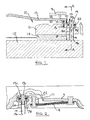
Figure 1 shows a radial section through part of a first embodiment of the present invention in an unworn clutch engaged position; -
Figure 2 shows a sectional view on line A-A ofFigure 1 ; -
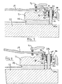
Figure 3 shows the embodiment ofFigure 1 with the clutch disengaged and about to make a wear adjustment; -
Figure 4 shows the embodiment ofFigure 1 with the clutch engaged after a wear adjustment has occurred; -
Figure 5 shows a radial section through part of a second embodiment of the present invention in an unworn clutch engaged position; -
Figure 6 shows a sectional view on line B-B ofFigure 5 ; -
Figure 7 shows the embodiment ofFigure 5 with the clutch disengaged and about to make a wear adjustment; -
Figure 8 shows the embodiment ofFigure 5 with the clutch engaged after a wear adjustment has occurred; -
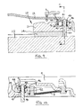
Figure 9 shows a radial section through part of a third embodiment of the present invention in an unworn clutch engaged position; -
Figure 10 shows a sectional view on line C-C ofFigure 9 ; -
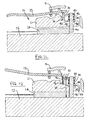
Figure 11 shows the embodiment ofFigure 9 with the clutch disengaged and about to make a wear adjustment; -
Figure 12 shows the embodiment ofFigure 9 with the clutch engaged after a wear adjustment has occurred; -
Figures 13 and 14 show plan and edge views respectively of part of the adjuster ramp arrangement used in the adjuster of the present invention; -
Figure 15 shows a radial section through part of a fourth embodiment of the present invention in an unworn clutch engaged position; -
Figure 16 shows a sectional view on line D-D ofFigure 15 ; -
Figure 17 shows the embodiment ofFigure 15 with the clutch disengaged and about to make a wear adjustment; -
Figure 18 shows a radial section through an alternative attachment for the sensor pin used inFigures 15 to 17 ; -
Figure 19 shows the shape of the alternative sensor pin used inFigure 18 ; -
Figure 20 to 22 show stages in the mounting of the alternative sensor pin, and -
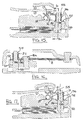
Figures 23 and 24 show the operation of the alternative sensor pin. - Referring to the drawings, a
vehicle friction clutch 10 in accordance with the present invention has apressure plate 11 biased towards an associatedflywheel 12 by adiaphragm spring 13 supported from aclutch cover 9. Aclutch drive disc 14 is provided for clamping between thepressure plate 11 and theflywheel 12 and a ramptype wear adjuster 15 is located in the thrust path between thediaphragm spring 13 and thepressure plate 11 to compensate for wear of thedrive disc 14. Lift straps 8 (seeFigure 2 ) are provided at circumferentially spaced locations between thecover 9 and thepressure plate 11 to ensure that thepressure plate 11 lift away from the flywheel when the clutch is disengaged. - The
wear adjuster 15 comprises a first ramp means in the form of aring 16 nearest to thepressure plate 11 and a second ramp means in the form of asecond ring 17 which is in contact with thefirst ring 16 but further away from the pressure plate and is also in contact with the diaphragm spring13. As can best be seen fromFigures 13 and 14 , the first andsecond rings coils springs 18 and therings ramp surfaces springs 18 to increase the combined effective thickness (see Y1 inFigure 1 ) of the rings to adjust the clutch for wear of thedisc 14 as will be explained below. - The wear adjuster also includes a wear sensor in the form of a hollow rolled
sensor pin 19 which is squashed as a friction grip in abore 20 in thepressure plate 11. One end 19a of thepin 19 engages theflywheel 12 when the clutch is engaged (seeFigure 1 ) and the pin is pushed through thebore 20 against the friction grip as the friction disc wears14. The other end 19b ofpin 19 means has a first abutment 19c which contacts a hold downmember 21 connected with thesecond ramp ring 17 and asecond abutment 19d which supports lift springs in the form of Bellevillesprings 22 which surroundpin 19 and which tend to bias the hold downmember 21 and thus the second ramp ring 17 away from thefirst ramp ring 16 and towards the first abutment 19c. In a typical construction there will be threesensor pins 19 positioned at 120 degree intervals around thepressure plate 11 to provide a balance arrangement. - When the clutch is engaged by the
diaphragm spring 13 there is a solid metal thrust path fromdiaphragm spring 13 viaramp rings pressure plate 11. Hence the effects oflift springs 22 are short circuited and have no influence on clutch engagement. - As the
clutch disc 14 wears, thepins 19 are pushed through thebores 20 to load thelift springs 22 so that, after sufficient wear has occurred, when the clutch is released, the loading of the lift spring means due to clutch disc wear, overcomes the effect of lift straps 8 (which tend to bias theramp rings ramp rings Figure 3 ). This gap is dependent on clutch disc wear and allows theadjuster springs 18 to rotate the two ramp rings relative to each other and thus increase the combined effective thickness of the ramp rings from Y1 inFigure 1 to Y2 inFigure 4. Figure 4 shows the adjusted clutch in the engaged condition immediately after a wear adjustment has been made when it can be seen that the distance Z of the diaphragm spring from the flywheel is the same as inFigure 1 so that the position and inclination (angle) of the diaphragm spring during operation of the clutch remains substantially constant as the clutch disc wears. -
Figures 5 to 8 show a second embodiment of the invention in the same basic positions as shown inFigures 1 to 4 . In this embodiment it is only the sensor pin construction which is different. Eachsensor pin 30 is solid and the friction grip in taperingbore 31 is provided by taperingcone shells 32 which surround thepin 30 and are biased into contact with aconical portion 33 of thebore 31 by acoil lift spring 34 which also acts against hold downmember 21.End 30b ofpin 30 is provided with agripping washer 35 which provides afirst abutment 36 against which hold downmember 21 is pressed bylift spring 34. The other end ofspring 34 acts against a second abutment provided by theupper surface 37 ofshells 32. Again there are threesensor pins 30 positioned at 120 degree intervals around thepressure plate 11. - As the
clutch disc 14 wears, thepins 30 are pushed through thebores 31 to load thelift springs 34 so that, after sufficient wear has occurred, when the clutch is released, the loading of the lift spring means due to clutch disc wear, overcomes the effect of lift straps 8 (which tend to bias theramp rings ramp rings Figure 7 ). This gap is dependent on clutch disc wear and allows theadjuster springs 18 to rotate the two ramp rings relative to each other and thus increase the combined effective thickness of the ramp rings from Y3 inFigure 5 to Y4 inFigure 8 so that the position and inclination (angle) of the diaphragm spring during operation of the clutch remains substantially constant as the clutch disc wears as explained above in relation toFigures 1 to 4 . -
Figures 9 to12 show a third embodiment of the invention in the same basic positions as shown inFigures 1 to 4 . Again in this embodiment it is only the sensor pin construction which is different. Eachsensor pin 40 is solid and the friction grip in bore 41 is provided by a self-griping washer 42 whose inner periphery grips thepin 40 and whose outer periphery grips ashoulder 43 in the bore 41. -
Pin 40 has a fist abutment provided by afirst circlip 45 and a second abutment provided by asecond circlip 44. Acoil lift spring 46 acts between thecirclips member 21 againstcirclip 45 . - As the
clutch disc 14 wears, thepins 40 are pushed through the bores 41 to load thelift springs 46 so that, after sufficient wear has occurred, when the clutch is released, the loading of the lift spring means due to clutch disc wear, overcomes the effect of lift straps 8 (which tend to bias theramp rings ramp rings Figure 11 ). This gap is dependent on clutch disc wear and allows theadjuster springs 18 to rotate the two ramp rings relative to each other and thus increase the combined effective thickness of the ramp rings from Y5 inFigure 9 to Y6 inFigure 12 so that the position and inclination (angle) of the diaphragm spring during operation of the clutch remains substantially constant as the clutch disc wears as explained above in relation toFigures 1 to 4 . -
Figures 15 to 17 show a third embodiment of the invention. Again in this embodiment it is only the sensor pin construction which is different. Eachsensor pin 50 is solid and the friction grip inbore 51 is provided by a self-gripingwasher 52 which is preassembled onto the pressure plate by therivet 8a which rivetslift strap 8 to the pressure plate. -
Pin 50 has a fist abutment provided by acirclip 55 and a second abutment provided by ashoulder 54. Acoil lift spring 56 acts between thecirclip 55 and theshoulder 54 to press sheet metal hold downmember 21, which is formed integrally with upper sheetmetal ramp ring 17, againstcirclip 55. - As the
clutch disc 14 wears, thepins 50 are pushed through thebores 51 to load the lift springs 56 so that, after sufficient wear has occurred, when the clutch is released, the loading of the lift spring means due to clutch disc wear, overcomes the effect of lift straps 8 (which tend to bias the ramp rings 16 and 17 towards each other) and biases the ramp rings 16 and 17 apart to allow a gap X to occur between the ramp rings (seeFigure 17 ). This gap is dependent on clutch disc wear and allows the adjuster springs 18 to rotate the two ramp rings relative to each other and thus increase the combined effective thickness of the ramp rings 16 and 17 so that the position and inclination (angle) of the diaphragm spring during operation of the clutch remains substantially constant as the clutch disc wears as explained above in relation to the previous embodiments. -
Figures 18 to 22 show an alternative form of attachment of thesensing pin 50 ofFigures 15 to 17 which eliminates thecirclip 55. - As can be seen from
Figure 18 , thesensing pin 50 has an upper end provided with a neck portion 60 aseating portion 61 and ahead portion 62 best seen inFigure 19 . The hold downmember 21, which is an integral part of the ramp ring 17 (as inFigures 15 to 17 ), has a slot 63 (seeFigure 21 ) which has a width through which theneck portion 60 ofpin 50 can pass and which leads to aseating hole 64 in which theseating portion 61 ofpin 50 can sit. - To mount the
pin 50 in thehole 64 thespring 56 is compressed (seeFigure 20 ) so that theneck portion 60 of thepin 50 aligns with theslot 63 and the neck potion is then slid through theslot 63 into thehole 64 as indicated by the arrow S inFigure 21 to the position shown inFigure 22 . Thespring 56 is then released so that theseating potion 61 of thepin 50 can enter and sit in thehole 64 and thus prevent the pin sliding out of theslot 63 as shown inFigure 18 . - With the sensing pin arrangement shown in
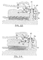
Figures 18 to 22 as theclutch disc 14 wears, thepins 50 are pushed through thebores 51 to load the lift springs 56 so that the head portion of the pins rise above the hold downmembers 21 to create a gap Y (seeFigure 23 ) dependent on the wear of the clutch disc. After sufficient wear has occurred, when the clutch is released, the loading of the lift spring means due to clutch disc wear, overcomes the effect of lift straps 8 (which tend to bias the ramp rings 16 and 17 towards each other) and biases the ramp rings 16 and 17 apart to allow a gap X to occur (seeFigure 24 ) between the ramp rings. This gap is again dependent on clutch disc wear and allows the adjuster springs 18 to rotate the two ramp rings relative to each other and thus increase the combined effective thickness of the ramp rings 16 and 17 so that the position and inclination (angle) of the diaphragm spring during operation of the clutch remains substantially constant as the clutch disc wears as explained above in relation to the previous embodiments. - As can be seen from the above the present invention provides a simple but effective wear adjuster mechanism for a vehicle clutch which is also reliable in operation.
Claims (13)
- A friction clutch for a motor vehicle, the clutch comprising a pressure plate biased towards an associated flywheel by a diaphragm spring, a clutch drive disc for clamping between the pressure plate and the associated flywheel, and a ramp type wear adjuster located in the thrust path between the diaphragm spring and the pressure plate to compensate for wear of the drive disc, the wear adjuster comprising a first ramp means nearest to the pressure plate and a second ramp means in contact with the first ramp means but further away from the pressure plate and also in contact with the diaphragm spring, the first and second ramp means being relatively rotatable about the axis of rotation of the pressure plate by an adjuster spring means to increase the combined effective thickness of the ramp means and hence maintain the travel of the diaphragm spring substantially constant as the clutch disc wears, the wear adjuster also including a wear sensor in the form of pin means carried in bore means in the pressure plate and held relative to the pressure plate by a friction grip, one end of the pin means engaging the flywheel when the clutch is engaged and the other end of the pin means having a first abutment which contacts a hold down member connected with the second ramp means, and lift spring means supported on a second abutment on the pin means and tending to bias the hold down member and thus the second ramp means away from the first ramp means and towards the first abutment, thus as the clutch disc wears the pin means is pushed through the bore means to load the lift spring means so that, after sufficient wear has occurred, when the clutch is released, the loading of the lift spring means due to clutch disc wear biases the ramp means apart to allow a gap to occur between the first and second ramp means which is dependent on clutch disc wear, so that the adjuster spring means can rotate the two ramp means relative to each other and thus increase the combined effective thickness of the ramp means to maintain the position and inclination angle) of the diaphragm spring substantially constant as the clutch disc wears.
- A clutch according to claim 1 in which the lift spring means surround the pin means.
- A clutch according to claim 1 or 2 in which the lift spring means comprises Belleville springs in series or parallel.
- A clutch according to claim 1 or 2 in which the lift spring means comprises coil springs.
- A clutch according to any one of claims 1 to 4 in which the pin means is provided as a rolled pin which is squashed in its bore means to provide the friction grip1 with the pressure plate.
- A clutch according to any one of claims 1 to 4 in which the friction grip is provided by tapering cone shells which surround the pin means and are biased into contact with a conical potion of the bore means by the lift spring means.
- A clutch according to any one of claims 1 to 4 in which the friction grip is provided by a self-griping washer whose inner periphery grips the pin means.
- A clutch according to any one of claims 1 to 7 in which both abutment means are provided by circlips carried by the pin.
- A clutch according to any one of claims 1 to 7 in which one abutment is provided by a circlip carried by the pin and the other abutment is provided by a shoulder formed on the pin.
- A clutch according to any one of claims 1 to 7 in which the abutment at the other end of the pin is provided by a head portion formed on the pin and the second abutment is provided by a shoulder formed on the pin.
- A clutch according to claim 10 in which the other end of the pin has axially adjacent head, seating and neck portions, the pin being connected with the hold down member via a slot in the hold down member which opens into a seating hole, the slot allowing the neck portion of the pin to pass therethrough into the seating hole when the lift spring means is compressed during assembly of the clutch so that the seating portion of the pin can sit in the seating hole when the lift spring means is released to hold the pin in the hole.
- A clutch according to any one of claims 1 to 11 provided with a plurality of wear sensors at circumferentially spaced location on the pressure plate.
- A clutch according to any one of claims 1 to 12 in which the adjuster spring means comprises coil springs which act circumferentially between the two ramp means.
Applications Claiming Priority (1)
| Application Number | Priority Date | Filing Date | Title |
|---|---|---|---|
| GB201304362A GB201304362D0 (en) | 2013-03-11 | 2013-03-11 | Vehicle clutches |
Publications (3)
| Publication Number | Publication Date |
|---|---|
| EP2778458A2 true EP2778458A2 (en) | 2014-09-17 |
| EP2778458A3 EP2778458A3 (en) | 2017-11-01 |
| EP2778458B1 EP2778458B1 (en) | 2019-01-30 |
Family
ID=48189722
Family Applications (1)
| Application Number | Title | Priority Date | Filing Date |
|---|---|---|---|
| EP14000555.4A Not-in-force EP2778458B1 (en) | 2013-03-11 | 2014-02-17 | Vehicle clutch including wear adjuster |
Country Status (2)
| Country | Link |
|---|---|
| EP (1) | EP2778458B1 (en) |
| GB (1) | GB201304362D0 (en) |
Cited By (2)
| Publication number | Priority date | Publication date | Assignee | Title |
|---|---|---|---|---|
| EP3184838A1 (en) * | 2015-12-21 | 2017-06-28 | AP Automotive Products Srl | Vehicle clutches |
| EP3809007A1 (en) | 2019-10-18 | 2021-04-21 | Raicam Driveline S.r.l. | Vehicle clutches |
Family Cites Families (3)
| Publication number | Priority date | Publication date | Assignee | Title |
|---|---|---|---|---|
| US5690203A (en) * | 1993-11-04 | 1997-11-25 | Fichtel & Sachs Ag | Motor vehicle friction clutch with automatic wear adjustment |
| JP3204832B2 (en) * | 1994-03-08 | 2001-09-04 | 株式会社エクセディ | Clutch cover assembly |
| DE19654882C2 (en) * | 1996-03-16 | 2001-09-20 | Mannesmann Sachs Ag | Motor vehicle friction clutch with automatic play compensation |
-
2013
- 2013-03-11 GB GB201304362A patent/GB201304362D0/en not_active Ceased
-
2014
- 2014-02-17 EP EP14000555.4A patent/EP2778458B1/en not_active Not-in-force
Cited By (2)
| Publication number | Priority date | Publication date | Assignee | Title |
|---|---|---|---|---|
| EP3184838A1 (en) * | 2015-12-21 | 2017-06-28 | AP Automotive Products Srl | Vehicle clutches |
| EP3809007A1 (en) | 2019-10-18 | 2021-04-21 | Raicam Driveline S.r.l. | Vehicle clutches |
Also Published As
| Publication number | Publication date |
|---|---|
| EP2778458B1 (en) | 2019-01-30 |
| EP2778458A3 (en) | 2017-11-01 |
| GB201304362D0 (en) | 2013-04-24 |
Similar Documents
| Publication | Publication Date | Title |
|---|---|---|
| US5690203A (en) | Motor vehicle friction clutch with automatic wear adjustment | |
| US9771985B2 (en) | Bracket barb pressure plate stop | |
| US5377803A (en) | Pressure plate arrangement for a motor vehicle friction clutch | |
| CA1111364A (en) | Automatic wear compensator for belleville spring clutches | |
| US5540313A (en) | Vehicular manual transmission having a friction clutch with automatic wear compensation | |
| US9133890B2 (en) | Friction clutch with adjusting device | |
| US8381890B2 (en) | Friction clutch having a wear adjuster | |
| US20100163361A1 (en) | Multiple disc clutch apparatus | |
| EP2778458B1 (en) | Vehicle clutch including wear adjuster | |
| JP2007321779A (en) | Tensioner | |
| JPH09504355A (en) | Friction clutch especially for automobiles | |
| KR100419587B1 (en) | Stopless self adjusting diaphragm clutch | |
| CN103502671B (en) | Compensation adjustment device for a friction clutch | |
| EP1290359B1 (en) | High torque retention joint for a tensioner | |
| JP2017510773A (en) | Multi-plate dual clutch | |
| CN105408650B (en) | Ramp ring for a ramp system of a compensating adjustment device and method for assembling a friction clutch | |
| US6325193B1 (en) | Friction clutch with an adjustment limiting device | |
| EP3184838B1 (en) | Vehicle clutches | |
| US2682943A (en) | Friction clutch with lever assembly | |
| US8997963B2 (en) | Cam hard stop for end of life | |
| US6915889B2 (en) | Pressure plate assembly for a friction clutch | |
| JP6775574B2 (en) | Friction clutch device | |
| JP2004301191A (en) | Vehicle friction clutch | |
| EP3809007A1 (en) | Vehicle clutches | |
| US6874607B2 (en) | Friction clutch |
Legal Events
| Date | Code | Title | Description |
|---|---|---|---|
| PUAI | Public reference made under article 153(3) epc to a published international application that has entered the european phase |
Free format text: ORIGINAL CODE: 0009012 |
|
| 17P | Request for examination filed |
Effective date: 20140217 |
|
| AK | Designated contracting states |
Kind code of ref document: A2 Designated state(s): AL AT BE BG CH CY CZ DE DK EE ES FI FR GB GR HR HU IE IS IT LI LT LU LV MC MK MT NL NO PL PT RO RS SE SI SK SM TR |
|
| AX | Request for extension of the european patent |
Extension state: BA ME |
|
| PUAL | Search report despatched |
Free format text: ORIGINAL CODE: 0009013 |
|
| AK | Designated contracting states |
Kind code of ref document: A3 Designated state(s): AL AT BE BG CH CY CZ DE DK EE ES FI FR GB GR HR HU IE IS IT LI LT LU LV MC MK MT NL NO PL PT RO RS SE SI SK SM TR |
|
| AX | Request for extension of the european patent |
Extension state: BA ME |
|
| RIC1 | Information provided on ipc code assigned before grant |
Ipc: F16D 13/75 20060101AFI20170925BHEP |
|
| STAA | Information on the status of an ep patent application or granted ep patent |
Free format text: STATUS: REQUEST FOR EXAMINATION WAS MADE |
|
| R17P | Request for examination filed (corrected) |
Effective date: 20180502 |
|
| RBV | Designated contracting states (corrected) |
Designated state(s): AL AT BE BG CH CY CZ DE DK EE ES FI FR GB GR HR HU IE IS IT LI LT LU LV MC MK MT NL NO PL PT RO RS SE SI SK SM TR |
|
| GRAP | Despatch of communication of intention to grant a patent |
Free format text: ORIGINAL CODE: EPIDOSNIGR1 |
|
| STAA | Information on the status of an ep patent application or granted ep patent |
Free format text: STATUS: GRANT OF PATENT IS INTENDED |
|
| INTG | Intention to grant announced |
Effective date: 20180627 |
|
| GRAJ | Information related to disapproval of communication of intention to grant by the applicant or resumption of examination proceedings by the epo deleted |
Free format text: ORIGINAL CODE: EPIDOSDIGR1 |
|
| STAA | Information on the status of an ep patent application or granted ep patent |
Free format text: STATUS: REQUEST FOR EXAMINATION WAS MADE |
|
| GRAJ | Information related to disapproval of communication of intention to grant by the applicant or resumption of examination proceedings by the epo deleted |
Free format text: ORIGINAL CODE: EPIDOSDIGR1 |
|
| GRAJ | Information related to disapproval of communication of intention to grant by the applicant or resumption of examination proceedings by the epo deleted |
Free format text: ORIGINAL CODE: EPIDOSDIGR1 |
|
| INTG | Intention to grant announced |
Effective date: 20180627 |
|
| GRAP | Despatch of communication of intention to grant a patent |
Free format text: ORIGINAL CODE: EPIDOSNIGR1 |
|
| STAA | Information on the status of an ep patent application or granted ep patent |
Free format text: STATUS: GRANT OF PATENT IS INTENDED |
|
| INTC | Intention to grant announced (deleted) | ||
| INTC | Intention to grant announced (deleted) | ||
| INTG | Intention to grant announced |
Effective date: 20180913 |
|
| GRAS | Grant fee paid |
Free format text: ORIGINAL CODE: EPIDOSNIGR3 |
|
| GRAA | (expected) grant |
Free format text: ORIGINAL CODE: 0009210 |
|
| STAA | Information on the status of an ep patent application or granted ep patent |
Free format text: STATUS: THE PATENT HAS BEEN GRANTED |
|
| AK | Designated contracting states |
Kind code of ref document: B1 Designated state(s): AL AT BE BG CH CY CZ DE DK EE ES FI FR GB GR HR HU IE IS IT LI LT LU LV MC MK MT NL NO PL PT RO RS SE SI SK SM TR |
|
| REG | Reference to a national code |
Ref country code: GB Ref legal event code: FG4D |
|
| REG | Reference to a national code |
Ref country code: CH Ref legal event code: EP |
|
| REG | Reference to a national code |
Ref country code: AT Ref legal event code: REF Ref document number: 1093520 Country of ref document: AT Kind code of ref document: T Effective date: 20190215 |
|
| REG | Reference to a national code |
Ref country code: IE Ref legal event code: FG4D |
|
| REG | Reference to a national code |
Ref country code: DE Ref legal event code: R096 Ref document number: 602014040232 Country of ref document: DE |
|
| REG | Reference to a national code |
Ref country code: LT Ref legal event code: MG4D |
|
| REG | Reference to a national code |
Ref country code: NL Ref legal event code: MP Effective date: 20190130 |
|
| PG25 | Lapsed in a contracting state [announced via postgrant information from national office to epo] |
Ref country code: SE Free format text: LAPSE BECAUSE OF FAILURE TO SUBMIT A TRANSLATION OF THE DESCRIPTION OR TO PAY THE FEE WITHIN THE PRESCRIBED TIME-LIMIT Effective date: 20190130 Ref country code: PT Free format text: LAPSE BECAUSE OF FAILURE TO SUBMIT A TRANSLATION OF THE DESCRIPTION OR TO PAY THE FEE WITHIN THE PRESCRIBED TIME-LIMIT Effective date: 20190530 Ref country code: ES Free format text: LAPSE BECAUSE OF FAILURE TO SUBMIT A TRANSLATION OF THE DESCRIPTION OR TO PAY THE FEE WITHIN THE PRESCRIBED TIME-LIMIT Effective date: 20190130 Ref country code: NL Free format text: LAPSE BECAUSE OF FAILURE TO SUBMIT A TRANSLATION OF THE DESCRIPTION OR TO PAY THE FEE WITHIN THE PRESCRIBED TIME-LIMIT Effective date: 20190130 Ref country code: LT Free format text: LAPSE BECAUSE OF FAILURE TO SUBMIT A TRANSLATION OF THE DESCRIPTION OR TO PAY THE FEE WITHIN THE PRESCRIBED TIME-LIMIT Effective date: 20190130 Ref country code: PL Free format text: LAPSE BECAUSE OF FAILURE TO SUBMIT A TRANSLATION OF THE DESCRIPTION OR TO PAY THE FEE WITHIN THE PRESCRIBED TIME-LIMIT Effective date: 20190130 Ref country code: NO Free format text: LAPSE BECAUSE OF FAILURE TO SUBMIT A TRANSLATION OF THE DESCRIPTION OR TO PAY THE FEE WITHIN THE PRESCRIBED TIME-LIMIT Effective date: 20190430 Ref country code: FI Free format text: LAPSE BECAUSE OF FAILURE TO SUBMIT A TRANSLATION OF THE DESCRIPTION OR TO PAY THE FEE WITHIN THE PRESCRIBED TIME-LIMIT Effective date: 20190130 |
|
| REG | Reference to a national code |
Ref country code: AT Ref legal event code: MK05 Ref document number: 1093520 Country of ref document: AT Kind code of ref document: T Effective date: 20190130 |
|
| PG25 | Lapsed in a contracting state [announced via postgrant information from national office to epo] |
Ref country code: IS Free format text: LAPSE BECAUSE OF FAILURE TO SUBMIT A TRANSLATION OF THE DESCRIPTION OR TO PAY THE FEE WITHIN THE PRESCRIBED TIME-LIMIT Effective date: 20190530 Ref country code: BG Free format text: LAPSE BECAUSE OF FAILURE TO SUBMIT A TRANSLATION OF THE DESCRIPTION OR TO PAY THE FEE WITHIN THE PRESCRIBED TIME-LIMIT Effective date: 20190430 Ref country code: LV Free format text: LAPSE BECAUSE OF FAILURE TO SUBMIT A TRANSLATION OF THE DESCRIPTION OR TO PAY THE FEE WITHIN THE PRESCRIBED TIME-LIMIT Effective date: 20190130 Ref country code: RS Free format text: LAPSE BECAUSE OF FAILURE TO SUBMIT A TRANSLATION OF THE DESCRIPTION OR TO PAY THE FEE WITHIN THE PRESCRIBED TIME-LIMIT Effective date: 20190130 Ref country code: GR Free format text: LAPSE BECAUSE OF FAILURE TO SUBMIT A TRANSLATION OF THE DESCRIPTION OR TO PAY THE FEE WITHIN THE PRESCRIBED TIME-LIMIT Effective date: 20190501 Ref country code: HR Free format text: LAPSE BECAUSE OF FAILURE TO SUBMIT A TRANSLATION OF THE DESCRIPTION OR TO PAY THE FEE WITHIN THE PRESCRIBED TIME-LIMIT Effective date: 20190130 |
|
| REG | Reference to a national code |
Ref country code: CH Ref legal event code: PL |
|
| PG25 | Lapsed in a contracting state [announced via postgrant information from national office to epo] |
Ref country code: MC Free format text: LAPSE BECAUSE OF FAILURE TO SUBMIT A TRANSLATION OF THE DESCRIPTION OR TO PAY THE FEE WITHIN THE PRESCRIBED TIME-LIMIT Effective date: 20190130 Ref country code: SK Free format text: LAPSE BECAUSE OF FAILURE TO SUBMIT A TRANSLATION OF THE DESCRIPTION OR TO PAY THE FEE WITHIN THE PRESCRIBED TIME-LIMIT Effective date: 20190130 Ref country code: AL Free format text: LAPSE BECAUSE OF FAILURE TO SUBMIT A TRANSLATION OF THE DESCRIPTION OR TO PAY THE FEE WITHIN THE PRESCRIBED TIME-LIMIT Effective date: 20190130 Ref country code: LU Free format text: LAPSE BECAUSE OF NON-PAYMENT OF DUE FEES Effective date: 20190217 Ref country code: DK Free format text: LAPSE BECAUSE OF FAILURE TO SUBMIT A TRANSLATION OF THE DESCRIPTION OR TO PAY THE FEE WITHIN THE PRESCRIBED TIME-LIMIT Effective date: 20190130 Ref country code: EE Free format text: LAPSE BECAUSE OF FAILURE TO SUBMIT A TRANSLATION OF THE DESCRIPTION OR TO PAY THE FEE WITHIN THE PRESCRIBED TIME-LIMIT Effective date: 20190130 Ref country code: RO Free format text: LAPSE BECAUSE OF FAILURE TO SUBMIT A TRANSLATION OF THE DESCRIPTION OR TO PAY THE FEE WITHIN THE PRESCRIBED TIME-LIMIT Effective date: 20190130 Ref country code: CZ Free format text: LAPSE BECAUSE OF FAILURE TO SUBMIT A TRANSLATION OF THE DESCRIPTION OR TO PAY THE FEE WITHIN THE PRESCRIBED TIME-LIMIT Effective date: 20190130 |
|
| REG | Reference to a national code |
Ref country code: DE Ref legal event code: R097 Ref document number: 602014040232 Country of ref document: DE |
|
| REG | Reference to a national code |
Ref country code: BE Ref legal event code: MM Effective date: 20190228 |
|
| REG | Reference to a national code |
Ref country code: IE Ref legal event code: MM4A |
|
| PG25 | Lapsed in a contracting state [announced via postgrant information from national office to epo] |
Ref country code: SM Free format text: LAPSE BECAUSE OF FAILURE TO SUBMIT A TRANSLATION OF THE DESCRIPTION OR TO PAY THE FEE WITHIN THE PRESCRIBED TIME-LIMIT Effective date: 20190130 |
|
| PLBE | No opposition filed within time limit |
Free format text: ORIGINAL CODE: 0009261 |
|
| STAA | Information on the status of an ep patent application or granted ep patent |
Free format text: STATUS: NO OPPOSITION FILED WITHIN TIME LIMIT |
|
| PG25 | Lapsed in a contracting state [announced via postgrant information from national office to epo] |
Ref country code: CH Free format text: LAPSE BECAUSE OF NON-PAYMENT OF DUE FEES Effective date: 20190228 Ref country code: LI Free format text: LAPSE BECAUSE OF NON-PAYMENT OF DUE FEES Effective date: 20190228 Ref country code: AT Free format text: LAPSE BECAUSE OF FAILURE TO SUBMIT A TRANSLATION OF THE DESCRIPTION OR TO PAY THE FEE WITHIN THE PRESCRIBED TIME-LIMIT Effective date: 20190130 |
|
| 26N | No opposition filed |
Effective date: 20191031 |
|
| PG25 | Lapsed in a contracting state [announced via postgrant information from national office to epo] |
Ref country code: IE Free format text: LAPSE BECAUSE OF NON-PAYMENT OF DUE FEES Effective date: 20190217 |
|
| PG25 | Lapsed in a contracting state [announced via postgrant information from national office to epo] |
Ref country code: BE Free format text: LAPSE BECAUSE OF NON-PAYMENT OF DUE FEES Effective date: 20190228 Ref country code: FR Free format text: LAPSE BECAUSE OF NON-PAYMENT OF DUE FEES Effective date: 20190330 Ref country code: SI Free format text: LAPSE BECAUSE OF FAILURE TO SUBMIT A TRANSLATION OF THE DESCRIPTION OR TO PAY THE FEE WITHIN THE PRESCRIBED TIME-LIMIT Effective date: 20190130 |
|
| PG25 | Lapsed in a contracting state [announced via postgrant information from national office to epo] |
Ref country code: TR Free format text: LAPSE BECAUSE OF FAILURE TO SUBMIT A TRANSLATION OF THE DESCRIPTION OR TO PAY THE FEE WITHIN THE PRESCRIBED TIME-LIMIT Effective date: 20190130 |
|
| PG25 | Lapsed in a contracting state [announced via postgrant information from national office to epo] |
Ref country code: MT Free format text: LAPSE BECAUSE OF NON-PAYMENT OF DUE FEES Effective date: 20190217 |
|
| REG | Reference to a national code |
Ref country code: DE Ref legal event code: R082 Ref document number: 602014040232 Country of ref document: DE Representative=s name: FRIESE GOEDEN PATENTANWAELTE PARTGMBB, DE Ref country code: DE Ref legal event code: R081 Ref document number: 602014040232 Country of ref document: DE Owner name: RAICAM DRIVELINE S.R.L., IT Free format text: FORMER OWNER: AP AUTOMOTIVE PRODUCTS SRL, MOIE DI MAIOLATI SPONTINI, ANCONA, IT |
|
| PG25 | Lapsed in a contracting state [announced via postgrant information from national office to epo] |
Ref country code: CY Free format text: LAPSE BECAUSE OF FAILURE TO SUBMIT A TRANSLATION OF THE DESCRIPTION OR TO PAY THE FEE WITHIN THE PRESCRIBED TIME-LIMIT Effective date: 20190130 |
|
| PG25 | Lapsed in a contracting state [announced via postgrant information from national office to epo] |
Ref country code: HU Free format text: LAPSE BECAUSE OF FAILURE TO SUBMIT A TRANSLATION OF THE DESCRIPTION OR TO PAY THE FEE WITHIN THE PRESCRIBED TIME-LIMIT; INVALID AB INITIO Effective date: 20140217 |
|
| PGFP | Annual fee paid to national office [announced via postgrant information from national office to epo] |
Ref country code: GB Payment date: 20220223 Year of fee payment: 9 Ref country code: DE Payment date: 20220217 Year of fee payment: 9 |
|
| PGFP | Annual fee paid to national office [announced via postgrant information from national office to epo] |
Ref country code: IT Payment date: 20220218 Year of fee payment: 9 |
|
| PG25 | Lapsed in a contracting state [announced via postgrant information from national office to epo] |
Ref country code: MK Free format text: LAPSE BECAUSE OF FAILURE TO SUBMIT A TRANSLATION OF THE DESCRIPTION OR TO PAY THE FEE WITHIN THE PRESCRIBED TIME-LIMIT Effective date: 20190130 |
|
| REG | Reference to a national code |
Ref country code: DE Ref legal event code: R119 Ref document number: 602014040232 Country of ref document: DE |
|
| GBPC | Gb: european patent ceased through non-payment of renewal fee |
Effective date: 20230217 |
|
| PG25 | Lapsed in a contracting state [announced via postgrant information from national office to epo] |
Ref country code: GB Free format text: LAPSE BECAUSE OF NON-PAYMENT OF DUE FEES Effective date: 20230217 |
|
| PG25 | Lapsed in a contracting state [announced via postgrant information from national office to epo] |
Ref country code: IT Free format text: LAPSE BECAUSE OF NON-PAYMENT OF DUE FEES Effective date: 20230217 Ref country code: GB Free format text: LAPSE BECAUSE OF NON-PAYMENT OF DUE FEES Effective date: 20230217 Ref country code: DE Free format text: LAPSE BECAUSE OF NON-PAYMENT OF DUE FEES Effective date: 20230901 |