EP2778452A1 - Fixed constant-velocity universal joint - Google Patents
Fixed constant-velocity universal joint Download PDFInfo
- Publication number
- EP2778452A1 EP2778452A1 EP12847139.8A EP12847139A EP2778452A1 EP 2778452 A1 EP2778452 A1 EP 2778452A1 EP 12847139 A EP12847139 A EP 12847139A EP 2778452 A1 EP2778452 A1 EP 2778452A1
- Authority
- EP
- European Patent Office
- Prior art keywords
- track groove
- joint
- center line
- ball raceway
- joint member
- Prior art date
- Legal status (The legal status is an assumption and is not a legal conclusion. Google has not performed a legal analysis and makes no representation as to the accuracy of the status listed.)
- Granted
Links
Images











Classifications
-
- F—MECHANICAL ENGINEERING; LIGHTING; HEATING; WEAPONS; BLASTING
- F16—ENGINEERING ELEMENTS AND UNITS; GENERAL MEASURES FOR PRODUCING AND MAINTAINING EFFECTIVE FUNCTIONING OF MACHINES OR INSTALLATIONS; THERMAL INSULATION IN GENERAL
- F16D—COUPLINGS FOR TRANSMITTING ROTATION; CLUTCHES; BRAKES
- F16D3/00—Yielding couplings, i.e. with means permitting movement between the connected parts during the drive
- F16D3/16—Universal joints in which flexibility is produced by means of pivots or sliding or rolling connecting parts
- F16D3/24—Universal joints in which flexibility is produced by means of pivots or sliding or rolling connecting parts comprising balls, rollers, or the like between overlapping driving faces, e.g. cogs, on both coupling parts
-
- F—MECHANICAL ENGINEERING; LIGHTING; HEATING; WEAPONS; BLASTING
- F16—ENGINEERING ELEMENTS AND UNITS; GENERAL MEASURES FOR PRODUCING AND MAINTAINING EFFECTIVE FUNCTIONING OF MACHINES OR INSTALLATIONS; THERMAL INSULATION IN GENERAL
- F16D—COUPLINGS FOR TRANSMITTING ROTATION; CLUTCHES; BRAKES
- F16D3/00—Yielding couplings, i.e. with means permitting movement between the connected parts during the drive
- F16D3/16—Universal joints in which flexibility is produced by means of pivots or sliding or rolling connecting parts
- F16D3/20—Universal joints in which flexibility is produced by means of pivots or sliding or rolling connecting parts one coupling part entering a sleeve of the other coupling part and connected thereto by sliding or rolling members
- F16D3/22—Universal joints in which flexibility is produced by means of pivots or sliding or rolling connecting parts one coupling part entering a sleeve of the other coupling part and connected thereto by sliding or rolling members the rolling members being balls, rollers, or the like, guided in grooves or sockets in both coupling parts
- F16D3/223—Universal joints in which flexibility is produced by means of pivots or sliding or rolling connecting parts one coupling part entering a sleeve of the other coupling part and connected thereto by sliding or rolling members the rolling members being balls, rollers, or the like, guided in grooves or sockets in both coupling parts the rolling members being guided in grooves in both coupling parts
-
- F—MECHANICAL ENGINEERING; LIGHTING; HEATING; WEAPONS; BLASTING
- F16—ENGINEERING ELEMENTS AND UNITS; GENERAL MEASURES FOR PRODUCING AND MAINTAINING EFFECTIVE FUNCTIONING OF MACHINES OR INSTALLATIONS; THERMAL INSULATION IN GENERAL
- F16D—COUPLINGS FOR TRANSMITTING ROTATION; CLUTCHES; BRAKES
- F16D3/00—Yielding couplings, i.e. with means permitting movement between the connected parts during the drive
- F16D3/16—Universal joints in which flexibility is produced by means of pivots or sliding or rolling connecting parts
- F16D3/20—Universal joints in which flexibility is produced by means of pivots or sliding or rolling connecting parts one coupling part entering a sleeve of the other coupling part and connected thereto by sliding or rolling members
- F16D3/22—Universal joints in which flexibility is produced by means of pivots or sliding or rolling connecting parts one coupling part entering a sleeve of the other coupling part and connected thereto by sliding or rolling members the rolling members being balls, rollers, or the like, guided in grooves or sockets in both coupling parts
- F16D3/223—Universal joints in which flexibility is produced by means of pivots or sliding or rolling connecting parts one coupling part entering a sleeve of the other coupling part and connected thereto by sliding or rolling members the rolling members being balls, rollers, or the like, guided in grooves or sockets in both coupling parts the rolling members being guided in grooves in both coupling parts
- F16D3/2237—Universal joints in which flexibility is produced by means of pivots or sliding or rolling connecting parts one coupling part entering a sleeve of the other coupling part and connected thereto by sliding or rolling members the rolling members being balls, rollers, or the like, guided in grooves or sockets in both coupling parts the rolling members being guided in grooves in both coupling parts where the grooves are composed of radii and adjoining straight lines, i.e. undercut free [UF] type joints
-
- F—MECHANICAL ENGINEERING; LIGHTING; HEATING; WEAPONS; BLASTING
- F16—ENGINEERING ELEMENTS AND UNITS; GENERAL MEASURES FOR PRODUCING AND MAINTAINING EFFECTIVE FUNCTIONING OF MACHINES OR INSTALLATIONS; THERMAL INSULATION IN GENERAL
- F16D—COUPLINGS FOR TRANSMITTING ROTATION; CLUTCHES; BRAKES
- F16D3/00—Yielding couplings, i.e. with means permitting movement between the connected parts during the drive
- F16D3/16—Universal joints in which flexibility is produced by means of pivots or sliding or rolling connecting parts
- F16D3/20—Universal joints in which flexibility is produced by means of pivots or sliding or rolling connecting parts one coupling part entering a sleeve of the other coupling part and connected thereto by sliding or rolling members
- F16D3/22—Universal joints in which flexibility is produced by means of pivots or sliding or rolling connecting parts one coupling part entering a sleeve of the other coupling part and connected thereto by sliding or rolling members the rolling members being balls, rollers, or the like, guided in grooves or sockets in both coupling parts
- F16D3/223—Universal joints in which flexibility is produced by means of pivots or sliding or rolling connecting parts one coupling part entering a sleeve of the other coupling part and connected thereto by sliding or rolling members the rolling members being balls, rollers, or the like, guided in grooves or sockets in both coupling parts the rolling members being guided in grooves in both coupling parts
- F16D3/224—Universal joints in which flexibility is produced by means of pivots or sliding or rolling connecting parts one coupling part entering a sleeve of the other coupling part and connected thereto by sliding or rolling members the rolling members being balls, rollers, or the like, guided in grooves or sockets in both coupling parts the rolling members being guided in grooves in both coupling parts the groove centre-lines in each coupling part lying on a sphere
-
- F—MECHANICAL ENGINEERING; LIGHTING; HEATING; WEAPONS; BLASTING
- F16—ENGINEERING ELEMENTS AND UNITS; GENERAL MEASURES FOR PRODUCING AND MAINTAINING EFFECTIVE FUNCTIONING OF MACHINES OR INSTALLATIONS; THERMAL INSULATION IN GENERAL
- F16D—COUPLINGS FOR TRANSMITTING ROTATION; CLUTCHES; BRAKES
- F16D3/00—Yielding couplings, i.e. with means permitting movement between the connected parts during the drive
- F16D3/16—Universal joints in which flexibility is produced by means of pivots or sliding or rolling connecting parts
- F16D3/20—Universal joints in which flexibility is produced by means of pivots or sliding or rolling connecting parts one coupling part entering a sleeve of the other coupling part and connected thereto by sliding or rolling members
- F16D3/22—Universal joints in which flexibility is produced by means of pivots or sliding or rolling connecting parts one coupling part entering a sleeve of the other coupling part and connected thereto by sliding or rolling members the rolling members being balls, rollers, or the like, guided in grooves or sockets in both coupling parts
- F16D3/223—Universal joints in which flexibility is produced by means of pivots or sliding or rolling connecting parts one coupling part entering a sleeve of the other coupling part and connected thereto by sliding or rolling members the rolling members being balls, rollers, or the like, guided in grooves or sockets in both coupling parts the rolling members being guided in grooves in both coupling parts
- F16D2003/22309—Details of grooves
Definitions
- the present invention relates to a fixed type constant velocity universal joint, and more specifically, to a fixed type constant velocity universal joint to be used in a power transmission system of automobiles and various industrial machines, for allowing only angular displacement between two shafts on a driving side and a driven side.
- a plunging type constant velocity universal joint capable of allowing axial displacement while forming an operating angle including a relatively low maximum operating angle is generally assembled on an inboard side (differential side) of an automotive front drive shaft.
- a fixed type constant velocity universal joint capable of forming high operating angles while avoiding axial displacement is assembled in consideration of steering of the wheel.
- FIGS. 21 illustrate a Rzeppa type constant velocity universal joint 101 as an example of the fixed type constant velocity universal joint to be used on the outboard side.
- FIG. 21a is a vertical sectional view of a state in which the operating angle is 0°
- FIG. 21b is a schematic view of a state in which the maximum operating angle is formed.
- the constant velocity universal joint 101 mainly includes an outer joint member 102, an inner joint member 103, balls 104, and a cage 105.
- Eight track grooves 107 are formed equiangularly in a spherical inner peripheral surface 106 of the outer joint member 102 to extend along an axial direction.
- Track grooves 109 opposed to the track grooves 107 of the outer joint member 102 are formed equiangularly in a spherical outer peripheral surface 108 of the inner joint member 103 to extend along the axial direction.
- the eight balls 104 for transmitting torque are interposed between the track grooves 107 of the outer joint member 102 and the track grooves 109 of the inner joint member 103, respectively.
- the cage 105 for holding the balls 104 is arranged between the spherical inner peripheral surface 106 of the outer joint member 102 and the spherical outer peripheral surface 108 of the inner joint member 103.
- An outer periphery of the outer joint member 102 and an outer periphery of a shaft coupled to the inner joint member 103 are covered with a boot, and grease is sealed inside the joint as a lubricant (not shown).
- the cage 105 has a spherical outer peripheral surface 112 fitted to the spherical inner peripheral surface 106 of the outer joint member 102, and a spherical inner peripheral surface 113 fitted to the spherical outer peripheral surface 108 of the inner joint member 103.
- the spherical outer peripheral surface 112 and the spherical inner peripheral surface 113 each have a curvature center formed at a joint center O.
- a curvature center Oo of a ball raceway center line x of each track groove 107 of the outer joint member 102 and a curvature center Oi of a ball raceway center line y of each track groove 109 of the inner joint member 103 are offset in the axial direction by equal distances with respect to the joint center O. Therefore, when the joint forms an operating angle, the balls 104 are always guided in a plane bisecting an angle formed between axial lines of the outer joint member 102 and the inner joint member 103. As a result, rotational torque is transmitted at a constant velocity between the two axes.
- a maximum operating angle ⁇ max which is defined as a main function of the fixed type constant velocity universal joint 101, depends on an angle causing interference between an inlet chamfer 110 provided at an opening rim of the outer joint member 102 and a shaft 111.
- an axial diameter d of the shaft 111 is determined for each joint size.
- the inlet chamfer 110 is formed while securing the effective track length of the outer joint member 102 is an important factor in securing the operating angle.
- the curvature center Oo of the ball raceway center line X of the track groove 107 of the outer joint member 102 is offset to an opening side, and hence there is an advantage in terms of the maximum operating angle.
- the maximum operating angle ⁇ max is approximately 47°.
- the Rzeppa type constant velocity universal joint 101 of an eight-ball type has a smaller track offset amount, a larger number of balls, and has a larger diameter.
- wedge angles formed between the opposing track grooves 107 and 109 of the outer joint member 102 and the inner joint member 103 are opened toward the opening side of the outer joint member 102.
- FIGS. 22 and 23 illustrate this constant velocity universal joint.
- FIG. 22 is a vertical sectional view of a state in which the operating angle is 0°
- FIGS. 23 are views of a state in which a high operating angle is formed.
- a constant velocity universal joint 121 mainly includes an outer joint member 122, an inner joint member 123, balls 124, and a cage 125.
- the constant velocity universal joint 121 is a constant velocity universal joint of the track groove crossing type.
- each track groove 129 of the inner joint member 123 has a ball raceway center line y, which is formed so as to be mirror-image symmetrical with the ball raceway center line x of the paired track groove 127 of the outer joint member 122 with respect to a plane P including a joint center O at the operating angle of 0°.
- the track groove 127 formed in a spherical inner peripheral surface 126 of the outer joint member 122 extends into an arc shape along the axial direction, and a curvature center of the track groove 127 is positioned at the joint center O.
- the track groove 129 opposed to the track groove 127 of the outer joint member 122 extends into an arc shape along the axial direction, and a curvature center of the track groove 129 is positioned at the joint center O.
- the eight balls 124 for transmitting torque are interposed in crossing portions between the track grooves 127 of the outer joint member 122 and the track grooves 129 of the inner joint member 123.
- the cage 125 for holding the balls 124 is arranged between the spherical inner peripheral surface 126 of the outer joint member 122 and the spherical outer peripheral surface 128 of the inner joint member 123.
- the cage 125 has a spherical outer peripheral surface 132 fitted to the spherical inner peripheral surface 126 of the outer joint member 122, and a spherical inner peripheral surface 133 fitted to the spherical outer peripheral surface 128 of the inner joint member 123.
- the spherical outer peripheral surface 132 and the spherical inner peripheral surface 133 each have a curvature center formed at the joint center O.
- curvature centers of the ball raceway center lines x and y of the respective track grooves 127 and 129 of the outer joint member 122 and the inner joint member 123 are not offset in the axial direction with respect to the joint center O.
- the track grooves 127 and 129 thus inclined and opposed cross each other, and the balls 124 are interposed in those crossing portions. Therefore, when the joint forms an operating angle, the balls 124 are always guided in a plane bisecting an angle formed between axial lines of the outer joint member 122 and the inner joint member 123. As a result, rotational torque is transmitted at a constant velocity between the two axes.
- the track grooves 127 of the outer joint member 122 that are adjacent to each other in the peripheral direction are inclined in the opposite directions.
- the track grooves 129 of the inner joint member 123 that are adjacent to each other in the peripheral direction are inclined in the opposite directions. Therefore, forces in the opposite directions are applied from the balls 124 to pocket portions 125a of the cage 125 that are adjacent to each other in the peripheral direction. Due to the forces in the opposite directions, the cage 125 is stabilized at the position of the joint center O.
- FIG. 23a is a view of a state in which the above-mentioned constant velocity universal joint forms a high operating angle
- FIG. 23b is an enlarged view of a positional relationship between the track groove 127 of the outer joint member 122 and the ball 124.
- the ball 124 is held in angular contact with the track groove 127 at a contact angle, and hence a contact point between the ball 124 and the track groove 127 is positioned on the broken line of FIG. 23b .
- the axial position of the contact point between the ball 124 and the track groove 127 is on a plane t passing through the center Ob of the ball 124 and perpendicular to the ball raceway center line x.
- Patent Document 1 JP 2009-250365 A
- FIG. 19a is a vertical sectional view
- FIG. 19b is a right-hand side view of FIG. 19a .
- an outer joint member 142 and an inner joint member 143 include track grooves 147 and 149 of a crossing type, respectively.
- Each track groove 147 of the outer joint member 142 includes a track groove portion 147a provided on an interior side of a joint center O and having an arc-shaped ball raceway center line xa about the joint center O defined as a curvature center, and a track groove portion 147b provided on an opening side of the joint center O and having a straight ball raceway center line xb.
- each track groove 149 of the inner joint member 143 includes a track groove portion 149b provided on the interior side of the joint center O and having a straight ball raceway center line yb, and a track groove portion 149a provided on the opening side of the joint center O and having an arc-shaped ball raceway center line ya about the joint center O defined as a curvature center.
- the track grooves 147 include track grooves 147A and 147B that are inclined in a peripheral direction with respect to a joint axial line and adjacent to each other in the peripheral direction with their inclination directions opposite to each other.
- the track grooves 149 include track grooves 149A and 149B that are inclined in the peripheral direction with respect to the joint axial line and adjacent to each other in the peripheral direction with their inclination directions opposite to each other.
- balls 144 are arranged in crossing portions of the paired track grooves 147A and 149A and the paired track grooves 147B and 149B of the outer joint member 142 and the inner joint member 143.
- an opening direction of a wedge angle formed between the track grooves 147A and 149A and an opening direction of a wedge angle formed between the track grooves 147B and 149B become opposite to each other, and hence forces in the opposite directions are applied from the balls 144 to pocket portions 145a of a cage 145 that are adjacent to each other in the peripheral direction. Due to the forces in the opposite directions, the cage 145 is stabilized at the position of the joint center O.
- the straight track groove portion 147b is formed on the opening side of the joint center O in the track groove 147 of the outer joint member 142, and hence the effective track length is increased.
- the track grooves 147 and 149 are generally held in contact with each ball 144 at a contact angle (approximately from 30° to 45°), and hence, as illustrated in FIG.
- the track grooves 147 and 149 are held in contact with the ball 144 at positions indicated by the broken lines on side surface sides of the track grooves 147 and 149, which are slightly spaced apart from groove bottoms of the track grooves 147 and 149.
- wedge angle components (not shown) due to the crossing between the track grooves 147 and 149 and wedge angle components ⁇ due to expansion between the groove bottoms of the track grooves 147 and 149 in a radial direction of the joint are both applied to the balls 144.
- the wedge angle components due to the crossing between the track grooves 147 and 149 are canceled and forces are balanced because the track grooves 147 and 149 are inclined in the directions alternately opposite to each other and hence forces in the opposite directions are applied from the balls 144 to the pocket portions 145a of the cage 145.
- the balls 144 within phase ranges of from 0° to 90° and from 270° to 360° in FIG. 19b are positioned in the straight track groove portions 147b and 149b. Due to a wedge angle component ⁇ 1 opened toward the opening side, a force toward the opening side is applied to the balls 144 within those phase ranges. On the other hand, the balls 144 within a phase range of from 90° to 270° are positioned in the arc-shaped track groove portions 147a and 149a.
- a wedge angle component ⁇ 2 which is generated due to the expansion in the radial direction of the joint, is zero in the balls within this phase range, and hence no push-out force is generated in the balls 144.
- the wedge angle components due to the crossing between the track grooves 147 and 149 and the wedge angle components ⁇ due to the expansion between the groove bottoms of the track grooves 147 and 149 in the radial direction of the joint are applied to the balls 144 in combination, the forces applied from the balls 144 to the pocket portions 145a of the cage 145 are not balanced with each other.
- the straight track groove portion 147b is formed in parallel to the joint axial line thus projected.
- the straight track groove portion 149b is formed in parallel to the joint axial line thus projected. Therefore, when the joint forms a high operating angle, the wedge angle formed between the straight track groove portions 147b and 149b is increased.
- the present invention has an object to provide a compact fixed type constant velocity universal joint that is suppressed in torque loss and heat generation, enhanced in efficiency, capable of forming high operating angles, and is excellent in strength and durability at the high operating angles.
- first track groove portions each comprising an arc-shaped ball raceway center line having a curvature center prevented from being offset in an axial direction with respect to a joint center are provided so as to be adaptable to a range of frequently used operating angles
- second track groove portions each comprising a straight part for increasing an effective track length at a maximum operating angle are provided so as to be adaptable to a range of less frequently used high operating angles.
- the inventors of the present invention have arrived at such an idea that a wedge angle between the second track groove portions at high operating angles can be decreased.
- a fixed type constant velocity universal joint comprising: an outer joint member having a spherical inner peripheral surface in which a plurality of track grooves are formed so as to extend in an axial direction of the outer joint member, the outer joint member having an opening side and an interior side spaced apart from each other in the axial direction; an inner joint member having a spherical outer peripheral surface in which a plurality of track grooves are formed so as to be paired with the plurality of track grooves of the outer joint member; a plurality of balls for transmitting torque, the plurality of balls being interposed between the plurality of track grooves of the outer joint member and the plurality of track grooves of the inner joint member; and a cage for holding the plurality of balls, the cage having a spherical outer peripheral surface and a spherical inner peripheral surface, which are fitted to the spherical inner peripheral surface of the outer joint member and
- joint axial line refers to a longitudinal axial line that is a joint rotation center, and corresponds to a joint axial line N-N in the embodiments described later. The same applies to a joint axial line described in the claims.
- the compact fixed type constant velocity universal joint that is suppressed in torque loss and heat generation, enhanced in efficiency, capable of forming high operating angles, and is excellent in strength and durability at the high operating angles.
- the ball raceway center line Xb of the each of the second track groove portions 7b is projected onto the corresponding one of the planes M, the straight part of the ball raceway center line Xb is formed so as to approach the joint axial line N-N as the distance to the opening side becomes smaller.
- the wedge angle between the straight track grooves portions 7b and 9b at high operating angles can be decreased, and hence the strength of the cage can be secured.
- an angle formed by a straight line L connecting the joint center O and the end portion A on the opening side of the arc-shaped ball raceway center line Xa of the each of the first track groove portions 7a with respect to the plane P including the joint center O at the operating angle of 0° is represented by ß, and the angle ß may be set appropriately depending on usage conditions.
- the angle ß is set to 3° to 10° in consideration of a range of a normal operating angle of the constant velocity universal joint for an automobile, and thus the constant velocity universal joint is widely applicable to various vehicle types.
- the angle ß is herein defined as the smallest angle among the angles formed by the straight line L with respect to the straight line on the plane P.
- the curvature center of the arc-shaped ball raceway center line Xa of the each of the above-mentioned first track groove portions 7a is arranged on the joint axial line N-N, and thus the track groove depths can be set equal to each other.
- the curvature center of the arc-shaped ball raceway center line Xa of the each of the first track groove portions 7a is offset in a radial direction of the outer joint member with respect to the joint axial line N-N, and thus the track groove depths on the interior side of the joint can be adjusted, with the result that optimum track groove depths can be secured.
- Each of the spherical outer peripheral surface and the spherical inner peripheral surface of the above-mentioned cage has a curvature center offset in the axial direction with respect to the joint center O.
- the thickness of the cage is increased as the distance to the opening side becomes smaller, with the result that the strength of the cage can be secured particularly at high operating angles.
- An entire region of the ball raceway center line Xb of the each of the above-mentioned second track groove portions 7b may have a straight shape, and the ball raceway center line Xb of the each of the second track groove portions 7b may be formed as a tangential line to the arc-shaped ball raceway center line Xa of the each of the first track groove portions 7a.
- the first track groove portions 7a and the second track groove portions 7b can be formed into a simple shape, with the result that the processes can be facilitated and the manufacturing cost can be reduced.
- the ball raceway center line Xb of the each of the above-mentioned second track groove portions 7b comprises an arc part having a curvature radius different from a curvature radius of the arc-shaped ball raceway center line Xa of the each of the first track groove portions 7a, and the arc part is connected to the end portion A of the arc-shaped ball raceway center line Xa of the each of the first track groove portions 7a.
- An inclination angle ⁇ of the ball raceway center line Xb of the each of the above-mentioned second track groove portions 7b may gradually be decreased as the distance to the opening side becomes smaller. Further, the straight part of the ball raceway center line Xb of the each of the second track groove portions 7b may be formed in parallel to the joint axial line N-N. Therefore, the interval on the approaching side is increased between the second track groove portions 7b, which are adjacent to each other in the peripheral direction, and the interval on the separating side is decreased therebetween. Thus, differences in intervals can be decreased in the peripheral direction.
- the number of the above-mentioned plurality of balls for transmitting torque is set to eight or ten.
- the compact fixed type constant velocity universal joint that is suppressed in torque loss and heat generation, enhanced in efficiency, capable of forming high operating angles, and is excellent in strength and durability at the high operating angles.
- Embodiments of the present invention are described with reference to FIGS. 1 to 18 .
- FIGS. 1 to 10 illustrate a first embodiment of the present invention.
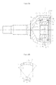
- FIGS. 1 illustrate a fixed type constant velocity universal joint according to the first embodiment.
- FIG. 1a is a partial vertical sectional view
- FIG. 1b is a right-hand side view of FIG. 1a .
- a constant velocity universal joint 1 according to this embodiment mainly comprises an outer joint member 2, an inner joint member 3, balls 4, and a cage 5.
- eight track grooves 7 of the outer joint member 2 comprise track grooves 7A and 7B that are inclined in a peripheral direction with respect to a joint axial line N-N and adjacent to each other in the peripheral direction with their inclination directions opposite to each other.
- eight track grooves 9 of the inner joint member 3 comprise track grooves 9A and 9B that are inclined in the peripheral direction with respect to the joint axial line N-N and adjacent to each other in the peripheral direction with their inclination directions opposite to each other.
- the eight balls 4 are arranged in crossing portions of the paired track grooves 7A and 9A and the paired track grooves 7B and 9B of the outer joint member 2 and the inner joint member 3. Details of the track grooves 7 and 9 are described later.
- FIG. 1a illustrates a vertical cross section of the joint.
- the term "ball raceway center line” is used herein to accurately describe the form and shape of each track groove extending in the axial direction, such as an inclined state and a curved state.
- the ball raceway center line herein refers to a trajectory of the center of the ball arranged in the track groove at the time of moving along the track groove.
- the inclined state of the track groove corresponds to an inclined state of the ball raceway center line
- the arc or straight shape of the track groove corresponds to an arc or straight shape of the ball raceway center line.
- each track groove 7 of the outer joint member 2 has a ball raceway center line X.
- the track groove 7 comprises a first track groove portion 7a having an arc-shaped ball raceway center line Xa about a joint center O defined as a curvature center, and a second track groove portion 7b having a straight ball raceway center line Xb.
- the ball raceway center line Xb of the second track groove portion 7b is smoothly connected to the ball raceway center line Xa of the first track groove portion 7a as a tangential line.
- each track groove 9 of the inner joint member 3 has a ball raceway center line Y.
- the track groove 9 comprises a first track groove portion 9a having an arc-shaped ball raceway center line Ya about the joint center O defined as a curvature center, and a second track groove portion 9b having a straight ball raceway center line Yb.
- the ball raceway center line Yb of the second track groove portion 9b is smoothly connected to the ball raceway center line Ya of the first track groove portion 9a as a tangential line.
- the curvature centers of the ball raceway center lines Xa and Ya of the first track groove portions 7a and 9a are arranged on the joint center O, that is, on the joint axial line N-N. As a result, the track groove depths can be set equal to each other and the processes can be facilitated.
- the track grooves 7 and 9 are formed into an elliptical shape or a Gothic arch shape in horizontal cross section, and the track grooves 7 and 9 are held in so-called angular contact with each ball 4 at a contact angle (approximately from 30° to 45°).
- a contact angle approximately from 30° to 45°.
- the ball 4 is held in contact with side surface sides of the track grooves 7 and 9, which are slightly spaced apart from groove bottoms of the track grooves 7 and 9.
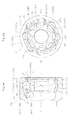
- FIGS. 2 detailed description is given of a state in which the track grooves 7 of the outer joint member 2 are inclined in the peripheral direction with respect to the joint axial line N-N.
- FIG. 2a is a partial vertical sectional view of the outer joint member 2
- FIG. 2b is a right-hand side view of the outer joint member 2.
- the track grooves 7 of the outer joint member 2 are represented by the reference symbols 7A and 7B to indicate a difference in inclination direction thereof.
- a plane M including the ball raceway center line X of each track groove 7A and the joint center O is inclined at an angle ⁇ with respect to the joint axial line N-N.
- a plane M including the ball raceway center line X of the track groove 7B and the joint center O is inclined at an angle ⁇ with respect to the joint axial line N-N in an opposite direction to the inclination direction of the track groove 7A.
- the entire ball raceway center line X of the track groove 7A that is, both the ball raceway center line Xa of the first track groove portion 7a and the ball raceway center line Xb of the second track groove portion 7b are formed in the plane M.
- the present invention is not limited thereto, and may be carried out in such an embodiment that only the ball raceway center line Xa of the first track groove portion 7a is included in the plane M.
- the planes M including at least the ball raceway center line Xa of the first track groove portion 7a and the joint center O be inclined with respect to the joint axial line N-N with their inclination directions opposite to each other in the first track groove portions 7a adjacent to each other in the peripheral direction.
- Reference symbol 7 represents the track grooves of the outer joint member 2 as a whole
- reference symbol 7a represents the first track groove portion
- reference symbol 7b represents the second track groove portion.
- reference symbols 7A and 7B represent the track grooves distinguished from each other based on the difference in inclination direction
- reference symbols 7Aa and 7Ba represent first track groove portions of the respective track grooves 7A and 7B
- reference symbols 7Ab and 7Bb represent second track groove portions of the respective track grooves 7A and 7B.
- the track grooves of the inner joint member 3 described later are represented by the reference symbols in a similar manner.
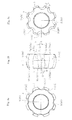
- FIG. 3b is a view of the outer peripheral surface of the inner joint member 3
- FIG. 3a is a left-hand side view of the inner joint member 3
- FIG. 3c is a right-hand side view of the inner joint member 3.
- the track grooves 9 of the inner joint member 3 are represented by the reference symbols 9A and 9B to indicate a difference in inclination direction thereof.
- a plane Q including the ball raceway center line Y of each track groove 9A and the joint center O is inclined at an angle ⁇ with respect to the joint axial line N-N.
- a plane Q including the ball raceway center line Y of the track groove 9B and the joint center O is inclined at an angle ⁇ with respect to the joint axial line N-N in an opposite direction to the inclination direction of the track groove 9A.
- the inclination angle ⁇ is preferably 4° to 12° in consideration of operability of the constant velocity universal joint 1 and a spherical width F between the closest sides of the track grooves of the inner joint member 3.
- the entire ball raceway center line Y of the track groove 9A that is, both the ball raceway center line Ya of the first track groove portion 9a and the ball raceway center line Yb of the second track groove portion 9b are formed in the plane Q.
- the present invention is not limited thereto, and may be carried out in such an embodiment that only the ball raceway center line Ya of the first track groove portion 9a is included in the plane Q.
- the planes Q including at least the ball raceway center line Ya of the first track groove portion 9a and the joint center O be inclined in the peripheral direction with respect to the joint axial line N-N with their inclination directions opposite to each other in the first track groove portions 9a adjacent to each other in the peripheral direction.
- the ball raceway center line Y of the track groove 9 of the inner joint member 3 is formed so as to be mirror-image symmetrical with the ball raceway center line X of the paired track groove 7 of the outer joint member 2 with respect to a plane P including the joint center O and being perpendicular to the joint axial line N-N at an operating angle of 0°.
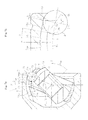
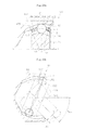
- FIG. 4 detailed description is given of the track grooves in the view take along the vertical cross section of the outer joint member 2.
- the partial vertical cross section of FIG. 4 corresponds to a sectional view taken along the above-mentioned plane M of FIG. 2a including the ball raceway center line X of the track groove 7A and the joint center O.
- FIG. 4 is not a vertical sectional view in the plane including the joint axial line N-N, but is a view illustrating a cross section inclined at the angle ⁇ .
- FIG. 4 is not a vertical sectional view in the plane including the joint axial line N-N, but is a view illustrating a cross section inclined at the angle ⁇ .
- a spherical inner peripheral surface 6 of the outer joint member 2 has the track grooves 7A formed along the axial direction.
- Each track groove 7A has the ball raceway center line X.
- the track groove 7A comprises the first track groove portion 7Aa having the arc-shaped ball raceway center line Xa about the joint center O defined as a curvature center (with no offset in the axial direction), and the second track groove portion 7Ab having the straight ball raceway center line Xb.
- the straight ball raceway center line Xb of the second track groove portion 7Ab is smoothly connected, as a tangential line, to an end portion A on an opening side of the ball raceway center line Xa of the first track groove portion 7Aa. That is, the end portion A is a connecting point between the first track groove portion 7Aa and the second track groove portion 7Ab.
- the end portion A is positioned on the opening side of the joint center O, and hence the straight ball raceway center line Xb of the second track groove portion 7Ab that is connected, as a tangential line, to the end portion A on the opening side of the ball raceway center line Xa of the first track groove portion 7Aa is formed so as to approach the joint axial line N-N (see FIG. 1a ) as the distance to the opening side becomes smaller.
- N-N see FIG. 1a
- L represents a straight line connecting the end portion A and the joint center O.
- a joint axial line N'-N' projected onto the plane M including the ball raceway center line X of the track groove 7A and the joint center O (see FIG. 2a ) is inclined at ⁇ with respect to the joint axial line N-N, and an angle formed between a perpendicular line K and the straight line L with respect to the joint center O on the axial line N'-N' is represented by ß'.
- the above-mentioned perpendicular line K is formed in the plane P including the joint center O at the operating angle of 0°.
- FIG. 5 is not a vertical sectional view in the plane including the joint axial line N-N, but is a view illustrating a cross section inclined at the angle ⁇ .
- FIG. 5 is not a vertical sectional view in the plane including the joint axial line N-N, but is a view illustrating a cross section inclined at the angle ⁇ .
- a spherical outer peripheral surface 8 of the inner joint member 3 has the track grooves 9A formed along the axial direction.
- Each track groove 9A has the ball raceway center line Y.
- the track groove 9A comprises the first track groove portion 9Aa having the arc-shaped ball raceway center line Ya about the joint center O defined as a curvature center (with no offset in the axial direction), and the second track groove portion 9Ab having the straight ball raceway center line Yb.
- the ball raceway center line Yb of the second track groove portion 9Ab is smoothly connected, as a tangential line, to an end portion B on an interior side of the ball raceway center line Ya of the first track groove portion 9Aa. That is, the end portion B is a connecting point between the first track groove portion 9Aa and the second track groove portion 9Ab.
- the end portion B is positioned on the interior side of the joint center O, and hence the straight ball raceway center line Yb of the second track groove portion 9Ab that is connected, as a tangential line, to the end portion B on the interior side of the ball raceway center line Ya of the first track groove portion 9Aa is formed so as to approach the joint axial line N-N (see FIG. 1a ) as the distance to the interior side becomes smaller.
- N-N see FIG. 1a
- R represents a straight line connecting the end portion B and the joint center O.
- a joint axial line N'-N' projected onto the plane Q including the ball raceway center line Y of the track groove 9A and the joint center O (see FIG. 3b ) is inclined at ⁇ with respect to the joint axial line N-N, and an angle formed between a perpendicular line K and the straight line R with respect to the joint center O on the axial line N'-N' is represented by ß'.
- the above-mentioned perpendicular line K is formed in the plane P including the joint center O at the operating angle of 0°.
- each ball 4 moves by ⁇ /2 with respect to the plane P including the joint center O in the outer joint member 2 and the inner joint member 3.
- the angle ß is determined based on 1/2 of a frequently used operating angle, and a contact range of the track groove for the ball 4 is determined within a range of the frequently used operating angle. Now, the frequently used operating angle is defined.
- the normal angle of the joint refers to an operating angle to be formed in a fixed type constant velocity universal joint of a front drive shaft of an automobile with one person onboard when the steering of the automobile is switched to a straightforward mode on a horizontal and flat road surface.
- the normal angle is selected and determined within a range of from 2° to 15° in accordance with design conditions for vehicle types.
- the frequently used operating angle refers to an operating angle to be formed in the fixed type constant velocity universal joint of the above-mentioned automobile during, for example, continuous travel on a curved road, instead of a high operating angle to be formed at the time of, for example, right and left turns at a traffic intersection. This operating angle is also determined in accordance with the design conditions for vehicle types.
- the frequently used operating angle is supposed to be 20° at maximum.
- the angle ß formed by each of the straight lines L and R with respect to the plane P including the joint center O at the operating angle of 0° is set to 3° to 10°.
- the angle ß is not limited to 3° to 10°, and may be set appropriately in accordance with the design conditions for vehicle types.
- the angle ß is set to 3° to 10°, the fixed type constant velocity universal joint of this embodiment is widely applicable to various vehicle types.
- the end portion A of the ball raceway center line Xa of the first track groove portion 7Aa corresponds to a center position of the ball that is moved to the end of the opening side along the axial direction at the frequently used operating angle.
- the end portion B of the ball raceway center line Ya of the first track groove portion 9Aa corresponds to a center position of the ball that is moved to the end of the interior side along the axial direction at the frequently used operating angle.
- the balls 4 are positioned between the first track groove portions 7Aa and 9Aa of the outer joint member 2 and the inner joint member 3 and between the first track groove portions 7Ba and 9Ba that are inclined in the opposite directions (see FIGS. 2 and 3 ). Therefore, forces in opposite directions are applied from the balls 4 to pocket portions 5a of the cage 5 that are adjacent to each other in the peripheral direction, and hence the cage 5 is stabilized at the position of the joint center O (see FIGS. 1 ).
- the balls 4 are fitted into the pocket portions 5a of the cage 5 with a clearance.
- the clearance be set to approximately 0 ⁇ m to 40 ⁇ m.
- FIG. 6 illustrates a state in which the constant velocity universal joint according to this embodiment forms the maximum operating angle.
- the second track groove portion 7Ab having the straight ball raceway center line Xb is formed on the opening side. Due to the second track groove portion 7Ab, the effective track length at the maximum operating angle can be secured and the excessive increase in wedge angle can be suppressed in a compact design. Therefore, even when a maximum operating angle ⁇ max is set as high as approximately 47° as illustrated in FIG. 6 , the contact state can be secured between the ball 4 and the track groove portion 7Ab under a state in which an inlet chamfer 10 having a necessary and sufficient size is provided, and the increase in wedge angle can be suppressed.
- the balls 4 arranged in the peripheral direction are temporarily separately positioned between the first track groove portions 7Aa and 9Aa (7Ba and 9Ba; see FIGS. 2a and 3b ) and between the second track groove portions 7Ab and 9Ab (7Bb and 9Bb; see FIGS. 2a and 3b ).
- the forces applied from the balls 4 to the pocket portions 5a of the cage 5 are not balanced with each other, and hence the contact forces are generated between the spherical contact portions 12 and 6 of the cage 5 and the outer joint member 2 and between the spherical contact portions 13 and 8 of the case 5 and the inner joint member 3, respectively.
- the constant velocity universal joint 1 according to this embodiment is comprehensively capable of suppressing the torque loss and heat generation.
- it is possible to attain a compact fixed type constant velocity universal joint that is suppressed in torque loss and heat generation, enhanced in efficiency, capable of forming high operating angles, and is excellent in strength and durability at the high operating angles.
- FIG. 7a is a vertical sectional view of the constant velocity universal joint 1
- FIG. 7b is an enlarged view of the contact state between the track groove 7A of the outer joint member 2 and the ball 4.
- FIGS. 7a and 7b also illustrate the track groove 7A of the outer joint member 2, and the illustration and description of the track groove 7B are omitted because the inclination direction of the track groove 7B is opposite to that of the track groove 7A and other structural details of the track groove 7B are the same as those of the track groove 7A.
- a center Ob of the ball 4 moves to a position corresponding to ⁇ max /2 with respect to the plane P including the joint center O at the operating angle of 0°.
- a contact point S between the ball 4 and the second track groove portion 7Ab becomes closest to the inlet chamfer 10.
- the straight ball raceway center line Xb of the second track groove portion 7Ab is connected, as a tangential line, to the end portion A of the arc-shaped ball raceway center line Xa of the first track groove portion 7Aa, and hence, in the vertical cross section of FIG. 7a , the straight ball raceway center line Xb is inclined in a direction of approaching the joint axial line N-N as the distance to the opening side of the outer joint member 2 becomes smaller.
- the contact point S between the ball 4 and the track groove portion 7Ab is positioned on a plane T passing through the center Ob of the ball 4 and perpendicular to the ball raceway center line Xb.
- the ball raceway center line Xb has the straight shape, and hence an axial distance w between the center Ob of the ball 4 and the contact point S is smaller than that of the related-art constant velocity universal joint illustrated in FIG. 23b , with the result that the effective track length is increased accordingly. Therefore, in this embodiment, a track allowance amount U can be secured between the edge portion of the inlet chamfer 10 and the contact point S at the maximum operating angle, and hence a sufficient contact state can be secured between the ball 4 and the track groove portion 7Ab.
- FIG. 8a is a vertical sectional view of the constant velocity universal joint 1
- FIG. 8(b) is an enlarged view of the state of the wedge angle between the track groove 7a (7Ab) of the outer joint member 2 and the track groove 9A (9Ab) of the inner joint member 3.
- FIGS. 8a and 8b also illustrate the track groove 7A of the outer joint member 2, and the illustration and description of the track groove 7B are omitted because the inclination direction of the track groove 7B is opposite to that of the track groove 7A and other structural details of the track groove 7B are the same as those of the track groove 7A.
- the track grooves 7A and 9A are held in angular contact with the ball 4 at a contact angle, and the ball raceway center lines X and Y of the track grooves 7A and 9A each have the inclination angle ⁇ (see FIGS. 2a and 3b ). Therefore, the wedge angle between the track grooves herein refers to an actual wedge angle formed at the contact points between the ball and the track grooves. In FIGS. 8a and 8b , however, the wedge angle is simply represented by the groove bottoms of the track grooves 7A and 9A. As illustrated in FIG.
- the straight ball raceway center line Xb of the second track groove portion 7Ab of the outer joint member 2 is connected, as a tangential line, to the end portion A of the arc-shaped ball raceway center line Xa of the first track groove portion 7Aa, and hence, in the vertical cross section of FIG.
- the straight ball raceway center line Xb at the operating angle of 0° is inclined in the direction of approaching the joint axial line N-N as the distance to the opening side of the outer joint member 2 becomes smaller.
- the straight ball raceway center line Yb of the second track groove portion 9Ab of the inner joint member 3 is inclined in an opposite direction to that of the straight ball raceway center line Xb of the outer joint member 2.
- the second track groove portions 7Ab and 9Ab at the operating angle of 0° are formed so as to be narrower on the opening side. Therefore, the wedge angle ⁇ at the maximum operating angle can be decreased.
- reference symbols 7Ab and 9Ab represent the second track groove portions of the outer joint member 2 and the inner joint member 3 of the constant velocity universal joint 1 according to this embodiment.
- reference symbols 7Ab' and 9Ab' represent second track groove portions according to Comparative Example 1 for investigation
- reference symbols 7Ab" and 9Ab" represent second track groove portions according to Comparative Example 2 for investigation.
- the second track groove portions 7Ab and 9Ab at the operating angle of 0° are formed so as to be narrower on the opening side. Therefore, the wedge angle at the maximum operating angle is decreased to ⁇ accordingly.
- the effective track length is larger in Comparative Examples 1 and 2, but in the practical use of the fixed type constant velocity universal joint, this embodiment is preferred because the effective track length at the maximum operating angle can be secured and the increase in wedge angle can be suppressed at the same time.
- FIGS. 9 are perspective views of the outer joint member 2 and the inner joint member 3 of the constant velocity universal joint according to this embodiment. Those perspective views illustrate the above-mentioned track grooves in a three-dimensional manner.
- the track grooves 7A and 7B inclined in the peripheral direction with respect to the joint axial line N-N are alternately formed in the spherical inner peripheral surface 6 of the outer joint member 2 with their inclination directions alternately opposite to each other.
- Each track groove 7A comprises the first track groove portion 7Aa and the second track groove portion 7Ab
- each track groove 7B comprises the first track groove portion 7Ba and the second track groove portion 7Bb.
- the inlet chamfer 10 is provided at the opening end of the outer joint member 2.
- each track groove 9A comprises the first track groove portion 9Aa and the second track groove portion 9Ab
- each track groove 9B comprises the first track groove portion 9Ba and the second track groove portion 9Bb.
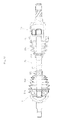
- FIG. 10 illustrates an automotive front drive shaft 20, to which the fixed type constant velocity universal joint 1 according to this embodiment is applied.
- the fixed type constant velocity universal joint 1 is coupled to one end of an intermediate shaft 11, and a plunging tripod type constant velocity universal joint 15 is coupled to another end thereof.
- bellows boots 16a and 16b are mounted and fixed with boot bands 18a, 18b, 18c, and 18d, respectively.
- Grease is sealed inside the joint as a lubricant.
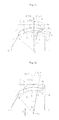
- FIG. 11 illustrates only an outer joint member of the fixed type constant velocity universal joint according to this embodiment.
- FIG. 11 is a sectional view taken along the plane M including the ball raceway center line X of the track groove 7A and the joint center O as in FIG. 4 (see FIG. 2a ; the same applies to the corresponding figures in the embodiments described later).
- FIG. 11 illustrates an upper half of the outer joint member in the radial direction with respect to the axial line.
- the fixed type constant velocity universal joint according to this embodiment is different from the above-mentioned fixed type constant velocity universal joint according to the first embodiment in that the second track groove portion comprises an arc part and a straight part.
- Other structural details of this embodiment are the same as those of the first embodiment.
- the parts having similar functions as those of the first embodiment are represented by the same reference symbols, and redundant description thereof is therefore omitted herein.
- the end portion A on the opening side of the ball raceway center line Xa of the first track groove portion 7a of the outer joint member 2 is the same as that of the first embodiment.
- the ball raceway center line Xb of the second track groove portion 7b comprises an arc-shaped ball raceway center line Xb1 and a straight ball raceway center line Xb2.
- the arc-shaped ball raceway center line Xb1 is connected to the end portion A on the opening side of the ball raceway center line Xa of the first track groove portion 7a.
- the curvature radius of the arc-shaped ball raceway center line Xb1 is smaller than the curvature radius of the ball raceway center line Xa of the first track groove portion 7a.
- the straight ball raceway center line Xb2 is connected, as a tangential line, to an end portion E on the opening side of the arc-shaped ball raceway center line Xb1.
- the ball raceway center line Y of the track groove 9 of the inner joint member 3 is formed so as to be mirror-image symmetrical with the ball raceway center line X of the paired track groove 7 of the outer joint member 2 with respect to the plane P including the joint center O at the operating angle of 0°.
- the curvature radius and an angle range F of the arc-shaped ball raceway center line Xb1 are set appropriately, thereby being capable of changing the inclination angle of the straight ball raceway center line Xb2 of the second track groove portion 7b in the direction of approaching the joint axial line N-N as the distance to the opening side becomes smaller.
- the wedge angle ⁇ at the maximum operating angle can be adjusted appropriately.
- the inclination angle in the direction of approaching the axial line N-N is increased by an angle ⁇ as compared to the first embodiment.
- FIG. 12 also illustrates only an outer joint member of the fixed type constant velocity universal joint according to this embodiment.
- the fixed type constant velocity universal joint according to this embodiment is different from the above-mentioned fixed type constant velocity universal joint according to the first embodiment in that the curvature center of the arc-shaped ball raceway center line of the first track groove portion is offset in the radial direction with respect to the joint axial line N-N, and accordingly, the structure of the straight ball raceway center line of the second track groove portion is adjusted.
- Other structural details of this embodiment are the same as those of the first embodiment.
- the parts having similar functions as those of the first embodiment are represented by the same reference symbols, and redundant description thereof is therefore omitted herein. The same applies to the embodiments described later.
- the end portion A on the opening side of the ball raceway center line Xa of the first track groove portion 7a of the outer joint member 2 is the same as that of the first embodiment.
- a curvature center O o3 of the ball raceway center line Xa of the first track groove portion 7a is not offset in the axial direction with respect to the joint center O, but is offset, however, by f 2 in the radial direction with respect to the joint axial line.
- the straight ball raceway center line Xb of the second track groove portion 7b is adjusted to be connected, as a tangential line, to the end portion A on the opening side of the ball raceway center line Xa of the first track groove portion 7a.
- the track groove depths on the interior side of the joint can be adjusted.
- the ball raceway center line Y of the track groove 9 of the inner joint member 3 is formed so as to be mirror-image symmetrical with the ball raceway center line X of the paired track groove 7 of the outer joint member 2 with respect to the plane P including the joint center O at the operating angle of 0°.
- a fixed type constant velocity universal joint according to a fourth embodiment of the present invention is described with reference to FIGS. 13 .
- the fixed type constant velocity universal joint according to this embodiment is different from the fixed type constant velocity universal joint according to the first embodiment in that the curvature centers of the spherical outer peripheral surface and the spherical inner peripheral surface of the cage are offset in the axial direction with respect to the joint center O.
- Other structural details of this embodiment are the same as those of the first embodiment.
- FIG. 13a is a partial vertical sectional view of the fixed type constant velocity universal joint
- FIG. 13b is a vertical sectional view of the cage.
- a curvature center O c1 of the spherical outer peripheral surface 12 of the cage 5 and a curvature center O c2 of the spherical inner peripheral surface 13 of the cage 5 are each offset by f 3 in the axial direction with respect to the joint center O.
- the thickness of the cage 5 is increased as the distance to the opening side becomes smaller, with the result that the strength of the cage 5 can be enhanced particularly at high operating angles.
- the balls 4 arranged in the peripheral direction are temporarily separately positioned between the first track groove portions 7Aa and 9Aa (7Ba and 9Ba; see FIGS. 2a and 3b ) and between the second track groove portions 7Ab and 9Ab (7Bb and 9Bb; see FIGS. 2a and 3b ).
- the pressing forces toward the opening side are applied from the balls 4 positioned between the second track groove portions 7Ab and 9Ab (7Bb and 9Bb) to the pocket portions 5a of the cage 5.
- the thickness of the cage 5 is increased as the distance to the opening side becomes smaller, with the result that the strength of the cage 5 can be enhanced.
- the track groove depths of the track groove portions 7a and 9b on the interior side can be increased.
- the inclined state of the track grooves 7 and 9 of the outer joint member 2 and the inner joint member 3 in the peripheral direction with respect to the joint axial line N-N, the structure of the cage 5, and the actions of the joint are similar to those of the fixed type constant velocity universal joint according to the first embodiment, and redundant description thereof is therefore omitted herein.
- a fixed type constant velocity universal joint according to a fifth embodiment of the present invention is described with reference to FIGS. 14 to 18 .
- the fixed type constant velocity universal joint according to this embodiment is different from the fixed type constant velocity universal joint according to the first embodiment in the structure of the second track groove portion.
- Other structural details of this embodiment are the same as those of the first embodiment.
- each track groove 7 of the outer joint member 2 has the ball raceway center line X.
- the track groove 7 comprises the first track groove portion 7a having the arc-shaped ball raceway center line Xa about the joint center O defined as a curvature center, and the second track groove portion 7b having the ball raceway center line Xb formed into a straight shape when being projected onto the plane M including the ball raceway center line Xa of the first track groove portion 7a and the joint center O (see FIG. 17 ).
- the ball raceway center line 7b of the second track groove portion 7b is smoothly connected to the ball raceway center line Xa of the first track groove portion 7a as a tangential line.
- each track groove 9 of the inner joint member 3 has the ball raceway center line Y.
- the track groove 9 comprises the first track groove portion 9a having the arc-shaped ball raceway center line Ya about the joint center O defined as a curvature center, and the second track portion 9b having the ball raceway center line Yb formed into a straight shape when being projected onto the plane Q including the ball raceway center line Ya of the first track groove portion 9Aa and the joint center O (see FIG. 18 ).
- the ball raceway center line Yb of the second track groove portion 9b is smoothly connected to the ball raceway center line Ya of the first track groove portion 9a as a tangential line.
- the shape in the region up to the end portion A on the opening side of the ball raceway center line Xa of the first track groove portion 7a of the outer joint member 2 is the same as that of the first embodiment.
- the ball raceway center line Xb of the second track groove portion 7b is different from that of the first embodiment.
- the ball raceway center line Xb of the second track groove portion 7b of the outer joint member 2 according to this embodiment is formed into a straight shape when being projected onto the plane M including the ball raceway center line Xa of the first track groove portion 7a and the joint center O (see FIG.
- the ball raceway center line Y of the track groove 9 of the inner joint member 3 is formed so as to be mirror-image symmetrical with the ball raceway center line X of the paired track groove 7 of the outer joint member 2 with respect to the plane P including the joint center O at the operating angle of 0°.
- the plane M including the ball raceway center line Xa of the first track groove portion 7Ba and the joint center O is inclined at the angle ⁇ with respect to the joint axial line N-N in the opposite direction to the inclination direction of the first track groove portion 7Aa.
- the first track groove portions 7Aa and 7Ba are formed in the plane M.
- the ball raceway center line Xb of the second track groove portion 7Ab is formed so that the ball raceway center line Xb is smoothly connected to the end portion A on the opening side of the ball raceway center line Xa of the first track groove portion 7Aa, then gently curved to have a gradually decreasing inclination angle ⁇ as the distance to the opening side becomes smaller, and is extended to have an inclination angle ⁇ of 0° in the vicinity of the opening end portion.
- the ball raceway center line Xb of the second track groove portion 7Bb which is inclined in the opposite direction, is formed in a similar manner.
- the plane Q including the ball raceway center line Ya of the first track groove portion 9Ba and the joint center O is inclined at the angle ⁇ with respect to the joint axial line N-N in the opposite direction to the inclination direction of the first track groove portion 9Aa.
- the ball raceway center line Yb of the second track groove portion 9Ab of the inner joint member 3 is formed so that the ball raceway center line Yb is smoothly connected to the end portion B on the interior side of the ball raceway center line Ya of the first track groove portion 9Aa, then gently curved to have a gradually decreasing inclination angle ⁇ as the distance to the interior side becomes smaller, and is extended to have an inclination angle ⁇ of 0° in the vicinity of the interior-side end portion.
- the ball raceway center line Yb of the second track groove portion 9Bb which is inclined in the opposite direction, is formed in a similar manner.
- the second track groove portions 7Ab and 7Bb of the outer joint member 2 and the second track groove portions 9Ab and 9Bb of the inner joint member 3 are formed as described above. Therefore, the interval on the approaching side is increased between the second track groove portions 7Ab and 7Bb, which are adjacent to each other in the peripheral direction, and the interval on the approaching side is also increased between the second track groove portions 9Ab and 9Bb, which are adjacent to each other in the peripheral direction. Thus, differences in intervals can be decreased in the peripheral direction.
- the ball raceway center line Xb of each of the second track groove portions 7Ab and 7Bb of the outer joint member 2 is formed so that the ball raceway center line Xb is smoothly connected to the end portion A on the opening side of the ball raceway center line Xa of each of the first track groove portions 7Aa and 7Ba, then gently curved to have a gradually decreasing inclination angle ⁇ as the distance to the opening side becomes smaller, and is extended to have an inclination angle ⁇ of 0° in the vicinity of the opening end portion.
- the ball raceway center line Yb of each of the second track groove portions 9Ab and 9Bb of the inner joint member 3 is formed so that the ball raceway center line Yb is smoothly connected to the end portion B on the interior side of the ball raceway center line Ya of each of the first track groove portions 9Aa and 9Ba, then gently curved to have a gradually decreasing inclination angle ⁇ as the distance to the opening side becomes smaller, and is extended to have an inclination angle ⁇ of 0° in the vicinity of the interior-side end portion.
- the present invention is not limited thereto.
- the ball raceway center line Xb of each of the second track groove portions 7Ab and 7Bb of the outer joint member 2 may be formed so that the ball raceway center line Xb is connected, in a shape of an arc having a relatively small curvature radius, to the end portion A on the opening side of the raceway center line Xa of each of the first track groove portions 7Aa and 7Ba and then extended to have an inclination angle ⁇ of 0° on the opening side.
- the ball raceway center line Yb of each of the second track groove portions 9Ab and 9Bb of the inner joint member 3 may be formed so that the ball raceway center line Yb is connected, in a shape of an arc having a relatively small curvature radius, to the end portion B on the interior side of the ball raceway center line Ya of each of the first track groove portions 9Aa and 9Ba and then extended to have an inclination angle ⁇ of 0° on the interior side.
- the number of the balls 4 is set to eight. However, the present invention is not limited thereto. Ten balls are also preferred, and twelve balls may also be applicable appropriately.
- the first track groove portion is not limited to a single arc, but may be formed of a plurality of arcs in consideration of the track groove depths and the like. Still further, the track grooves are arranged at a regular pitch in the peripheral direction, but may be arranged at an irregular pitch. Still further, the inclination angles ⁇ of the first track groove portions with respect to the joint axial line N-N are equal to each other in all the track grooves, but the present invention is not limited thereto.
- the inclination angle ⁇ of a pair of the first track groove portions of the outer joint member and the inner joint member may be formed so as to be unequal to the inclination angle ⁇ of another pair of the first track groove portions thereof. That is, it is only necessary that the inclination angles be set so that the axial forces of the balls are applied in a balanced manner as a whole to all the pocket portions of the cage in the peripheral direction.
- the track grooves and the balls are held in angular contact at a contact angle in the embodiments described above, but the present invention is not limited thereto.
- the track grooves and the balls may be held in circular contact by forming the track grooves into a circular shape in horizontal cross section.
Landscapes
- Engineering & Computer Science (AREA)
- General Engineering & Computer Science (AREA)
- Mechanical Engineering (AREA)
- Rolling Contact Bearings (AREA)
- Bearings For Parts Moving Linearly (AREA)
- Forging (AREA)
Abstract
Description
- The present invention relates to a fixed type constant velocity universal joint, and more specifically, to a fixed type constant velocity universal joint to be used in a power transmission system of automobiles and various industrial machines, for allowing only angular displacement between two shafts on a driving side and a driven side.
- For example, a plunging type constant velocity universal joint capable of allowing axial displacement while forming an operating angle including a relatively low maximum operating angle is generally assembled on an inboard side (differential side) of an automotive front drive shaft. On an outboard side (wheel side) thereof, a fixed type constant velocity universal joint capable of forming high operating angles while avoiding axial displacement is assembled in consideration of steering of the wheel.
-
FIGS. 21 illustrate a Rzeppa type constant velocityuniversal joint 101 as an example of the fixed type constant velocity universal joint to be used on the outboard side.FIG. 21a is a vertical sectional view of a state in which the operating angle is 0°, andFIG. 21b is a schematic view of a state in which the maximum operating angle is formed. As illustrated inFIG. 21a , the constant velocityuniversal joint 101 mainly includes an outerjoint member 102, an innerjoint member 103,balls 104, and acage 105. Eighttrack grooves 107 are formed equiangularly in a spherical innerperipheral surface 106 of theouter joint member 102 to extend along an axial direction.Track grooves 109 opposed to thetrack grooves 107 of theouter joint member 102 are formed equiangularly in a spherical outerperipheral surface 108 of theinner joint member 103 to extend along the axial direction. The eightballs 104 for transmitting torque are interposed between thetrack grooves 107 of theouter joint member 102 and thetrack grooves 109 of theinner joint member 103, respectively. Thecage 105 for holding theballs 104 is arranged between the spherical innerperipheral surface 106 of theouter joint member 102 and the spherical outerperipheral surface 108 of theinner joint member 103. An outer periphery of theouter joint member 102 and an outer periphery of a shaft coupled to theinner joint member 103 are covered with a boot, and grease is sealed inside the joint as a lubricant (not shown). - As illustrated in
FIG. 21a , thecage 105 has a spherical outerperipheral surface 112 fitted to the spherical innerperipheral surface 106 of theouter joint member 102, and a spherical innerperipheral surface 113 fitted to the spherical outerperipheral surface 108 of theinner joint member 103. The spherical outerperipheral surface 112 and the spherical innerperipheral surface 113 each have a curvature center formed at a joint center O. On the other hand, a curvature center Oo of a ball raceway center line x of eachtrack groove 107 of theouter joint member 102 and a curvature center Oi of a ball raceway center line y of eachtrack groove 109 of theinner joint member 103 are offset in the axial direction by equal distances with respect to the joint center O. Therefore, when the joint forms an operating angle, theballs 104 are always guided in a plane bisecting an angle formed between axial lines of the outerjoint member 102 and theinner joint member 103. As a result, rotational torque is transmitted at a constant velocity between the two axes. - As illustrated in
FIG. 21b , a maximum operating angle θmax, which is defined as a main function of the fixed type constant velocityuniversal joint 101, depends on an angle causing interference between aninlet chamfer 110 provided at an opening rim of the outerjoint member 102 and a shaft 111. In order to secure permissible torque to be transmitted, an axial diameter d of the shaft 111 is determined for each joint size. When alarge inlet chamfer 110 is formed, the length of eachtrack groove 107 of theouter joint member 102, on which theball 104 is brought into abutment (hereinafter referred to as "effective track length"), is insufficient. As a result, theball 104 may drop off thetrack groove 107, and the rotational torque cannot be transmitted. Therefore, how theinlet chamfer 110 is formed while securing the effective track length of the outerjoint member 102 is an important factor in securing the operating angle. In the Rzeppa type constant velocityuniversal joint 101, the curvature center Oo of the ball raceway center line X of thetrack groove 107 of theouter joint member 102 is offset to an opening side, and hence there is an advantage in terms of the maximum operating angle. However, the maximum operating angle θmax is approximately 47°. - Further, as compared to a related-art six-ball constant velocity universal joint, the Rzeppa type constant velocity
universal joint 101 of an eight-ball type has a smaller track offset amount, a larger number of balls, and has a larger diameter. Thus, it is possible to attain a highly efficient constant velocity universal joint that is lightweight and compact, and is suppressed in torque loss. However, at an operating angle of 0°, wedge angles formed between theopposing track grooves joint member 102 and theinner joint member 103 are opened toward the opening side of the outerjoint member 102. Therefore, due to axial forces applied from thetrack grooves spherical contact portions outer joint member 102 and thecage 105 and thespherical contact portions joint member 103 and thecage 105 are generated in a certain direction. Thus, this structure leads to restriction on achieving even higher efficiency and less heat generation. - In order to achieve even higher efficiency and less heat generation than those can be achieved by the above-mentioned Rzeppa type constant velocity
universal joint 101 of the eight-ball type, a fixed type constant velocity universal joint of a track groove crossing type has been proposed (Patent Document 1).FIGS. 22 and23 illustrate this constant velocity universal joint.FIG. 22 is a vertical sectional view of a state in which the operating angle is 0°, andFIGS. 23 are views of a state in which a high operating angle is formed. As illustrated inFIG. 22 , a constant velocityuniversal joint 121 mainly includes an outerjoint member 122, aninner joint member 123,balls 124, and acage 125. The constant velocityuniversal joint 121 is a constant velocity universal joint of the track groove crossing type. Although illustration is omitted, planes including ball raceway center lines x of eighttrack grooves 127 of theouter joint member 122 are inclined with respect to a joint axial line n-n with their inclination directions opposite to each other in thetrack grooves 127 adjacent to each other in a peripheral direction. In addition, eachtrack groove 129 of theinner joint member 123 has a ball raceway center line y, which is formed so as to be mirror-image symmetrical with the ball raceway center line x of the pairedtrack groove 127 of theouter joint member 122 with respect to a plane P including a joint center O at the operating angle of 0°. - In the vertical cross section illustrated in
FIG. 22 , thetrack groove 127 formed in a spherical innerperipheral surface 126 of theouter joint member 122 extends into an arc shape along the axial direction, and a curvature center of thetrack groove 127 is positioned at the joint center O. In a spherical outerperipheral surface 128 of theinner joint member 123, thetrack groove 129 opposed to thetrack groove 127 of theouter joint member 122 extends into an arc shape along the axial direction, and a curvature center of thetrack groove 129 is positioned at the joint center O. The eightballs 124 for transmitting torque are interposed in crossing portions between thetrack grooves 127 of theouter joint member 122 and thetrack grooves 129 of theinner joint member 123. Thecage 125 for holding theballs 124 is arranged between the spherical innerperipheral surface 126 of theouter joint member 122 and the spherical outerperipheral surface 128 of theinner joint member 123. Thecage 125 has a spherical outerperipheral surface 132 fitted to the spherical innerperipheral surface 126 of theouter joint member 122, and a spherical innerperipheral surface 133 fitted to the spherical outerperipheral surface 128 of theinner joint member 123. The spherical outerperipheral surface 132 and the spherical innerperipheral surface 133 each have a curvature center formed at the joint center O. In the constant velocityuniversal joint 121, curvature centers of the ball raceway center lines x and y of therespective track grooves outer joint member 122 and theinner joint member 123 are not offset in the axial direction with respect to the joint center O. However, thetrack grooves balls 124 are interposed in those crossing portions. Therefore, when the joint forms an operating angle, theballs 124 are always guided in a plane bisecting an angle formed between axial lines of the outerjoint member 122 and theinner joint member 123. As a result, rotational torque is transmitted at a constant velocity between the two axes. - In the above-mentioned fixed type constant velocity
universal joint 121 of the track groove crossing type, thetrack grooves 127 of theouter joint member 122 that are adjacent to each other in the peripheral direction are inclined in the opposite directions. Further, thetrack grooves 129 of theinner joint member 123 that are adjacent to each other in the peripheral direction are inclined in the opposite directions. Therefore, forces in the opposite directions are applied from theballs 124 topocket portions 125a of thecage 125 that are adjacent to each other in the peripheral direction. Due to the forces in the opposite directions, thecage 125 is stabilized at the position of the joint center O. Thus, a contact force between the spherical outerperipheral surface 132 of thecage 125 and the spherical innerperipheral surface 126 of theouter joint member 122, and a contact force between the spherical innerperipheral surface 133 of thecage 125 and the spherical outerperipheral surface 128 of theinner joint member 123 are suppressed. Accordingly, the joint is smoothly operated under high load and in high speed rotation, and torque loss and heat generation are suppressed. As a result, the durability is enhanced. - The above-mentioned fixed type constant velocity
universal joint 121 is excellent as a joint suppressed in heat generation, but has the following problem inherent therein. Detailed description thereof is given with reference toFIGS. 23. FIG. 23a is a view of a state in which the above-mentioned constant velocity universal joint forms a high operating angle, andFIG. 23b is an enlarged view of a positional relationship between thetrack groove 127 of the outerjoint member 122 and theball 124. When the joint forms a high operating angle θ as illustrated inFIG. 23a , a center Ob of theball 124 moves to a position corresponding to θ/2 with respect to the plane P including the joint center O at the operating angle of 0°. Theball 124 is held in angular contact with thetrack groove 127 at a contact angle, and hence a contact point between theball 124 and thetrack groove 127 is positioned on the broken line ofFIG. 23b . In addition, the axial position of the contact point between theball 124 and thetrack groove 127 is on a plane t passing through the center Ob of theball 124 and perpendicular to the ball raceway center line x. In the above-mentioned fixed type constant velocityuniversal joint 121, when alarge inlet chamfer 130 is formed in theouter joint member 122, theball 124 at the high operating angle θ is positioned on an outer side of theinlet chamfer 130, and hence theball 124 may drop off thetrack groove 127. The reason is because the curvature center of the arc-shaped track groove 127 matches with the joint center O and hence an axial distance w between the center Ob of theball 124 and a contact point s is large, resulting in an insufficient effective track length. Thus, there is a problem in that high operating angles cannot be formed. - Patent Document 1:
JP 2009-250365 A - In view of the above-mentioned problem inherent in the related art, the inventors have investigated the possibility of employing a straight shape for the track groove on the opening side of the joint center O so as to achieve high operating angles in the fixed type constant velocity universal joint of the track groove crossing type disclosed in
Patent Document 1. This constant velocity universal joint corresponds to a constant velocity universal joint illustrated inFIGS. 19. FIG. 19a is a vertical sectional view, andFIG. 19b is a right-hand side view ofFIG. 19a . As illustrated inFIG. 19a , in a constant velocityuniversal joint 141, an outerjoint member 142 and an innerjoint member 143 includetrack grooves track groove 147 of the outerjoint member 142 includes atrack groove portion 147a provided on an interior side of a joint center O and having an arc-shaped ball raceway center line xa about the joint center O defined as a curvature center, and atrack groove portion 147b provided on an opening side of the joint center O and having a straight ball raceway center line xb. On the other hand, eachtrack groove 149 of the innerjoint member 143 includes atrack groove portion 149b provided on the interior side of the joint center O and having a straight ball raceway center line yb, and atrack groove portion 149a provided on the opening side of the joint center O and having an arc-shaped ball raceway center line ya about the joint center O defined as a curvature center. - In addition, as illustrated in
FIG. 19b , thetrack grooves 147 includetrack grooves track grooves 149 includetrack grooves balls 144 are arranged in crossing portions of the pairedtrack grooves track grooves joint member 142 and the innerjoint member 143. Therefore, when transmitting torque at the operating angle of 0° as illustrated inFIGS. 19 , an opening direction of a wedge angle formed between thetrack grooves track grooves balls 144 to pocketportions 145a of acage 145 that are adjacent to each other in the peripheral direction. Due to the forces in the opposite directions, thecage 145 is stabilized at the position of the joint center O. Thus, a contact force between a spherical outerperipheral surface 152 of thecage 145 and a spherical innerperipheral surface 146 of the outerjoint member 142, and a contact force between a spherical innerperipheral surface 153 of thecage 145 and a spherical outerperipheral surface 148 of the innerjoint member 143 are suppressed. Accordingly, the joint is smoothly operated under high load and in high speed rotation, and torque loss and heat generation are suppressed. As a result, the durability is enhanced. - As described above, in the track groove crossing type, the straight
track groove portion 147b is formed on the opening side of the joint center O in thetrack groove 147 of the outerjoint member 142, and hence the effective track length is increased. However, it has been found that, when a frequently used operating angle is formed, there is a problem in terms of suppression of the torque loss and heat generation of the joint. The reason is described with reference toFIG. 20 . Thetrack grooves ball 144 at a contact angle (approximately from 30° to 45°), and hence, as illustrated inFIG. 20 , thetrack grooves ball 144 at positions indicated by the broken lines on side surface sides of thetrack grooves track grooves track grooves track grooves balls 144. Of those wedge angle components, the wedge angle components due to the crossing between thetrack grooves track grooves balls 144 to thepocket portions 145a of thecage 145. - However, as illustrated in
FIG. 20 , in the case of the wedge angle components α due to the expansion between the groove bottoms of thetrack grooves balls 144 within phase ranges of from 0° to 90° and from 270° to 360° inFIG. 19b are positioned in the straighttrack groove portions balls 144 within those phase ranges. On the other hand, theballs 144 within a phase range of from 90° to 270° are positioned in the arc-shapedtrack groove portions balls 144. Thus, when the wedge angle components due to the crossing between thetrack grooves track grooves balls 144 in combination, the forces applied from theballs 144 to thepocket portions 145a of thecage 145 are not balanced with each other. As a result, there arises a problem in that the contact forces between thespherical contact portions cage 145 and the outerjoint member 142 and between thespherical contact portions cage 145 and the innerjoint member 143 cannot be suppressed. In particular, it has been found that this problem is serious in terms of suppression of the torque loss and heat generation in a range of the frequently used operating angles including a normal operating angle. - Further, in the constant velocity
universal joint 141 illustrated inFIGS. 19 and20 , when the joint axial line n-n is projected onto a plane including the ball raceway center line x and the joint center O, the straighttrack groove portion 147b is formed in parallel to the joint axial line thus projected. When the joint axial line n-n is projected onto a plane including the ball raceway center line y and the joint center O, on the other hand, the straighttrack groove portion 149b is formed in parallel to the joint axial line thus projected. Therefore, when the joint forms a high operating angle, the wedge angle formed between the straighttrack groove portions ball 144 interposed between the straighttrack groove portions cage 145 is increased. Thus, it has been found that the strength of thecage 145 at the high operating angle becomes a problem. - In view of the above-mentioned problems, the present invention has an object to provide a compact fixed type constant velocity universal joint that is suppressed in torque loss and heat generation, enhanced in efficiency, capable of forming high operating angles, and is excellent in strength and durability at the high operating angles.
- As a result of various investigations for achieving the above-mentioned object, the inventors of the present invention have arrived at the following novel idea. In order to suppress torque loss and heat generation and to achieve higher efficiency, track grooves are caused to cross each other in a peripheral direction. Further, first track groove portions each comprising an arc-shaped ball raceway center line having a curvature center prevented from being offset in an axial direction with respect to a joint center are provided so as to be adaptable to a range of frequently used operating angles, and second track groove portions each comprising a straight part for increasing an effective track length at a maximum operating angle are provided so as to be adaptable to a range of less frequently used high operating angles. In addition, the inventors of the present invention have arrived at such an idea that a wedge angle between the second track groove portions at high operating angles can be decreased.
- As a technical measure to achieve the above-mentioned object, according to one embodiment of the present invention, there is provided a fixed type constant velocity universal joint, comprising: an outer joint member having a spherical inner peripheral surface in which a plurality of track grooves are formed so as to extend in an axial direction of the outer joint member, the outer joint member having an opening side and an interior side spaced apart from each other in the axial direction; an inner joint member having a spherical outer peripheral surface in which a plurality of track grooves are formed so as to be paired with the plurality of track grooves of the outer joint member; a plurality of balls for transmitting torque, the plurality of balls being interposed between the plurality of track grooves of the outer joint member and the plurality of track grooves of the inner joint member; and a cage for holding the plurality of balls, the cage having a spherical outer peripheral surface and a spherical inner peripheral surface, which are fitted to the spherical inner peripheral surface of the outer joint member and the spherical outer peripheral surface of the inner joint member, respectively, wherein the plurality of track grooves of the outer joint member comprise: first track groove portions 7a positioned on the interior side; and second track groove portions 7b positioned on the opening side, wherein each of the first track groove portions 7a comprises an arc-shaped ball raceway center line Xa having a curvature center prevented from being offset in the axial direction with respect to a joint center O, wherein planes M each including at least the arc-shaped ball raceway center line Xa and the joint center O are inclined with respect to a joint axial line N-N with their inclination directions opposite to each other in the first track groove portions 7a, which are adjacent to each other in a peripheral direction of the outer joint member, wherein each of the second track groove portions 7b comprises a ball raceway center line Xb having a straight part when being projected onto corresponding one of the planes M, wherein the straight part is formed in an inclined manner to approach the joint axial line N-N as a distance to the opening side becomes smaller, wherein the arc-shaped ball raceway center line Xa of the each of the first track groove portions 7a comprises an end portion A positioned on the opening side in the axial direction with respect to the joint center O, wherein the ball raceway center line Xb of the each of the second track groove portions 7b is connected to the end portion A, and wherein each of the plurality of track grooves of the inner joint member comprises a ball raceway center line Y, which is formed so as to be mirror-image symmetrical with a ball raceway center line X of corresponding one of the plurality of paired track grooves of the outer joint member with respect to a plane P including the joint center O at an operating angle of 0°. The above-mentioned "joint axial line" herein refers to a longitudinal axial line that is a joint rotation center, and corresponds to a joint axial line N-N in the embodiments described later. The same applies to a joint axial line described in the claims.
- With the above-mentioned structure, it is possible to attain the compact fixed type constant velocity universal joint that is suppressed in torque loss and heat generation, enhanced in efficiency, capable of forming high operating angles, and is excellent in strength and durability at the high operating angles. In particular, when the ball raceway center line Xb of the each of the second
track groove portions 7b is projected onto the corresponding one of the planes M, the straight part of the ball raceway center line Xb is formed so as to approach the joint axial line N-N as the distance to the opening side becomes smaller. Thus, the wedge angle between the straighttrack grooves portions - Specifically, an angle formed by a straight line L connecting the joint center O and the end portion A on the opening side of the arc-shaped ball raceway center line Xa of the each of the first
track groove portions 7a with respect to the plane P including the joint center O at the operating angle of 0° is represented by ß, and the angle ß may be set appropriately depending on usage conditions. The angle ß is set to 3° to 10° in consideration of a range of a normal operating angle of the constant velocity universal joint for an automobile, and thus the constant velocity universal joint is widely applicable to various vehicle types. Note that, the angle ß is herein defined as the smallest angle among the angles formed by the straight line L with respect to the straight line on the plane P. In addition, the same applies to the embodiments and the claims. - The curvature center of the arc-shaped ball raceway center line Xa of the each of the above-mentioned first
track groove portions 7a is arranged on the joint axial line N-N, and thus the track groove depths can be set equal to each other. Alternatively, the curvature center of the arc-shaped ball raceway center line Xa of the each of the firsttrack groove portions 7a is offset in a radial direction of the outer joint member with respect to the joint axial line N-N, and thus the track groove depths on the interior side of the joint can be adjusted, with the result that optimum track groove depths can be secured. - Each of the spherical outer peripheral surface and the spherical inner peripheral surface of the above-mentioned cage has a curvature center offset in the axial direction with respect to the joint center O. Thus, the thickness of the cage is increased as the distance to the opening side becomes smaller, with the result that the strength of the cage can be secured particularly at high operating angles.
- An entire region of the ball raceway center line Xb of the each of the above-mentioned second
track groove portions 7b may have a straight shape, and the ball raceway center line Xb of the each of the secondtrack groove portions 7b may be formed as a tangential line to the arc-shaped ball raceway center line Xa of the each of the firsttrack groove portions 7a. Thus, the firsttrack groove portions 7a and the secondtrack groove portions 7b can be formed into a simple shape, with the result that the processes can be facilitated and the manufacturing cost can be reduced. - The ball raceway center line Xb of the each of the above-mentioned second
track groove portions 7b comprises an arc part having a curvature radius different from a curvature radius of the arc-shaped ball raceway center line Xa of the each of the firsttrack groove portions 7a, and the arc part is connected to the end portion A of the arc-shaped ball raceway center line Xa of the each of the firsttrack groove portions 7a. Thus, the wedge angle between the second track groove portions can be adjusted. - An inclination angle γ of the ball raceway center line Xb of the each of the above-mentioned second
track groove portions 7b may gradually be decreased as the distance to the opening side becomes smaller. Further, the straight part of the ball raceway center line Xb of the each of the secondtrack groove portions 7b may be formed in parallel to the joint axial line N-N. Therefore, the interval on the approaching side is increased between the secondtrack groove portions 7b, which are adjacent to each other in the peripheral direction, and the interval on the separating side is decreased therebetween. Thus, differences in intervals can be decreased in the peripheral direction. As a result, a difference in contact area on the opening side between the respective regions of the spherical inner peripheral surface of the outer joint member and a difference in contact area on the interior side between the respective regions of the spherical outer peripheral surface of the inner joint member can be decreased, and hence the spherical contact portions between the cage and the outer joint member and between the cage and the inner joint member can be arranged in a balanced manner. Thus, the fixed type constant velocity universal joint can be operated more smoothly. - The number of the above-mentioned plurality of balls for transmitting torque is set to eight or ten. Thus, it is possible to attain a fixed type constant velocity universal joint and therefore an automotive drive shaft that are lightweight and compact, enhanced in efficiency, and are capable of forming high operating angles.
- According to one embodiment of the present invention, it is possible to attain the compact fixed type constant velocity universal joint that is suppressed in torque loss and heat generation, enhanced in efficiency, capable of forming high operating angles, and is excellent in strength and durability at the high operating angles. In particular, it is possible to decrease the wedge angle between the straight track grooves at the high operating angles, thereby being capable of securing the strength of the cage.
-
-
FIG. 1a is a partial vertical sectional view of a fixed type constant velocity universal joint according to a first embodiment of the present invention. -
FIG. 1b is a side view of the fixed type constant velocity universal joint. -
FIG. 2a is a partial vertical sectional view of an outer joint member of the fixed type constant velocity universal joint. -
FIG. 2b is a side view of the outer joint member. -
FIG. 3a is a left-hand side view of an inner joint member of the fixed type constant velocity universal joint. -
FIG. 3b is a view of an outer peripheral surface of the inner joint member. -
FIG. 3c is a right-hand side view of the inner joint member. -
FIG. 4 is a partial vertical sectional view of details of track grooves of the outer joint member. -
FIG. 5 is a vertical sectional view of details of track grooves of the inner joint member. -
FIG. 6 is a schematic view of a state in which the joint forms a maximum operating angle. -
FIG. 7a is a view of a contact state between a ball and the track groove at the time when the joint forms the maximum operating angle. -
FIG. 7b is a partially enlarged view ofFIG. 7a . -
FIG. 8a is a view of a wedge angle in a state in which the joint forms the maximum operating angle. -
FIG. 8b is a view of changes in wedge angle. -
FIG. 9a is a perspective view of the outer joint member. -
FIG. 9b is a perspective view of the inner joint member. -
FIG. 10 is a view of a state in which the fixed type constant velocity universal joint is used in an automotive drive shaft. -
FIG. 11 is a vertical sectional view of an outer joint member of a fixed type constant velocity universal joint according to a second embodiment of the present invention. -
FIG. 12 is a vertical sectional view of an outer joint member of a fixed type constant velocity universal joint according to a third embodiment of the present invention. -
FIG. 13a is a partial vertical sectional view of a fixed type constant velocity universal joint according to a fourth embodiment of the present invention. -
FIG. 13b is a vertical sectional view of a cage of the fixed type constant velocity universal joint. -
FIG. 14 is a partial vertical sectional view of a fixed type constant velocity universal joint according to a fifth embodiment of the present invention. -
FIG. 15 is a vertical sectional view of an outer joint member of the fixed type constant velocity universal joint. -
FIG. 16 is a vertical sectional view of an inner joint member of the fixed type constant velocity universal joint. -
FIG. 17 is a partial vertical sectional view of an inner peripheral shape of the outer joint member of the fixed type constant velocity universal joint. -
FIG. 18 is a view of an outer peripheral shape of the inner joint member of the fixed type constant velocity universal joint. -
FIG. 19a is a vertical sectional view of a fixed type constant velocity universal joint, for illustrating technical findings in the process to arrive at the present invention. -
FIG. 19b is a side view of the fixed type constant velocity universal joint. -
FIG. 20 is a view illustrating the technical findings in the process to arrive at the present invention. -
FIG. 21a is a vertical sectional view of a related-art fixed type constant velocity universal joint. -
FIG. 21b is a view of a state in which the fixed type constant velocity universal joint forms the maximum operating angle. -
FIG. 22 is a vertical sectional view of another related-art fixed type constant velocity universal joint. -
FIG. 23a is a vertical sectional view of the related-art fixed type constant velocity universal joint. -
FIG. 23b is a partially enlarged view of the fixed type constant velocity universal joint. - Embodiments of the present invention are described with reference to
FIGS. 1 to 18 . -
FIGS. 1 to 10 illustrate a first embodiment of the present invention.FIGS. 1 illustrate a fixed type constant velocity universal joint according to the first embodiment.FIG. 1a is a partial vertical sectional view, andFIG. 1b is a right-hand side view ofFIG. 1a . A constant velocityuniversal joint 1 according to this embodiment mainly comprises an outerjoint member 2, an innerjoint member 3,balls 4, and acage 5. As illustrated inFIGS. 1b ,2 , and3 , eighttrack grooves 7 of the outerjoint member 2comprise track grooves track grooves 9 of the innerjoint member 3comprise track grooves balls 4 are arranged in crossing portions of the pairedtrack grooves track grooves joint member 2 and the innerjoint member 3. Details of thetrack grooves -
FIG. 1a illustrates a vertical cross section of the joint. The term "ball raceway center line" is used herein to accurately describe the form and shape of each track groove extending in the axial direction, such as an inclined state and a curved state. The ball raceway center line herein refers to a trajectory of the center of the ball arranged in the track groove at the time of moving along the track groove. Thus, the inclined state of the track groove corresponds to an inclined state of the ball raceway center line, and the arc or straight shape of the track groove corresponds to an arc or straight shape of the ball raceway center line. - As illustrated in
FIG. 1a , eachtrack groove 7 of the outerjoint member 2 has a ball raceway center line X. Thetrack groove 7 comprises a firsttrack groove portion 7a having an arc-shaped ball raceway center line Xa about a joint center O defined as a curvature center, and a secondtrack groove portion 7b having a straight ball raceway center line Xb. The ball raceway center line Xb of the secondtrack groove portion 7b is smoothly connected to the ball raceway center line Xa of the firsttrack groove portion 7a as a tangential line. On the other hand, eachtrack groove 9 of the innerjoint member 3 has a ball raceway center line Y. Thetrack groove 9 comprises a firsttrack groove portion 9a having an arc-shaped ball raceway center line Ya about the joint center O defined as a curvature center, and a secondtrack groove portion 9b having a straight ball raceway center line Yb. The ball raceway center line Yb of the secondtrack groove portion 9b is smoothly connected to the ball raceway center line Ya of the firsttrack groove portion 9a as a tangential line. The curvature centers of the ball raceway center lines Xa and Ya of the firsttrack groove portions track grooves track grooves ball 4 at a contact angle (approximately from 30° to 45°). Thus, theball 4 is held in contact with side surface sides of thetrack grooves track grooves - Referring to
FIGS. 2 , detailed description is given of a state in which thetrack grooves 7 of the outerjoint member 2 are inclined in the peripheral direction with respect to the joint axial line N-N.FIG. 2a is a partial vertical sectional view of the outerjoint member 2, andFIG. 2b is a right-hand side view of the outerjoint member 2. Thetrack grooves 7 of the outerjoint member 2 are represented by thereference symbols FIG. 2a , a plane M including the ball raceway center line X of eachtrack groove 7A and the joint center O is inclined at an angle γ with respect to the joint axial line N-N. In addition, in the case of eachtrack groove 7B adjacent to thetrack groove 7A in the peripheral direction, although illustration is omitted, a plane M including the ball raceway center line X of thetrack groove 7B and the joint center O is inclined at an angle γ with respect to the joint axial line N-N in an opposite direction to the inclination direction of thetrack groove 7A. In this embodiment, the entire ball raceway center line X of thetrack groove 7A, that is, both the ball raceway center line Xa of the firsttrack groove portion 7a and the ball raceway center line Xb of the secondtrack groove portion 7b are formed in the plane M. However, the present invention is not limited thereto, and may be carried out in such an embodiment that only the ball raceway center line Xa of the firsttrack groove portion 7a is included in the plane M. Thus, it is only necessary that the planes M including at least the ball raceway center line Xa of the firsttrack groove portion 7a and the joint center O be inclined with respect to the joint axial line N-N with their inclination directions opposite to each other in the firsttrack groove portions 7a adjacent to each other in the peripheral direction. - Now, supplementary description is given of the reference symbols of the track grooves.
Reference symbol 7 represents the track grooves of the outerjoint member 2 as a whole,reference symbol 7a represents the first track groove portion, andreference symbol 7b represents the second track groove portion. Further,reference symbols respective track grooves respective track grooves joint member 3 described later are represented by the reference symbols in a similar manner. - Next, referring to
FIGS. 3 , detailed description is given of a state in which thetrack grooves 9 of the innerjoint member 3 are inclined in the peripheral direction with respect to the joint axial line N-N.FIG. 3b is a view of the outer peripheral surface of the innerjoint member 3,FIG. 3a is a left-hand side view of the innerjoint member 3, andFIG. 3c is a right-hand side view of the innerjoint member 3. Thetrack grooves 9 of the innerjoint member 3 are represented by thereference symbols FIG. 3b , a plane Q including the ball raceway center line Y of eachtrack groove 9A and the joint center O is inclined at an angle γ with respect to the joint axial line N-N. In addition, in the case of eachtrack groove 9B adjacent to thetrack groove 9A in the peripheral direction, although illustration is omitted, a plane Q including the ball raceway center line Y of thetrack groove 9B and the joint center O is inclined at an angle γ with respect to the joint axial line N-N in an opposite direction to the inclination direction of thetrack groove 9A. The inclination angle γ is preferably 4° to 12° in consideration of operability of the constant velocityuniversal joint 1 and a spherical width F between the closest sides of the track grooves of the innerjoint member 3. Further, similarly to the outer joint member described above, in this embodiment, the entire ball raceway center line Y of thetrack groove 9A, that is, both the ball raceway center line Ya of the firsttrack groove portion 9a and the ball raceway center line Yb of the secondtrack groove portion 9b are formed in the plane Q. However, the present invention is not limited thereto, and may be carried out in such an embodiment that only the ball raceway center line Ya of the firsttrack groove portion 9a is included in the plane Q. Thus, it is only necessary that the planes Q including at least the ball raceway center line Ya of the firsttrack groove portion 9a and the joint center O be inclined in the peripheral direction with respect to the joint axial line N-N with their inclination directions opposite to each other in the firsttrack groove portions 9a adjacent to each other in the peripheral direction. The ball raceway center line Y of thetrack groove 9 of the innerjoint member 3 is formed so as to be mirror-image symmetrical with the ball raceway center line X of the pairedtrack groove 7 of the outerjoint member 2 with respect to a plane P including the joint center O and being perpendicular to the joint axial line N-N at an operating angle of 0°. - Referring to
FIG. 4 , detailed description is given of the track grooves in the view take along the vertical cross section of the outerjoint member 2. The partial vertical cross section ofFIG. 4 corresponds to a sectional view taken along the above-mentioned plane M ofFIG. 2a including the ball raceway center line X of thetrack groove 7A and the joint center O. Thus, in a strict sense,FIG. 4 is not a vertical sectional view in the plane including the joint axial line N-N, but is a view illustrating a cross section inclined at the angle γ.FIG. 4 illustrates thetrack groove 7A of the outerjoint member 2, and the illustration and description of thetrack groove 7B are omitted because the inclination direction of thetrack groove 7B is opposite to that of thetrack groove 7A and other structural details of thetrack groove 7B are the same as those of thetrack groove 7A. A spherical innerperipheral surface 6 of the outerjoint member 2 has thetrack grooves 7A formed along the axial direction. Eachtrack groove 7A has the ball raceway center line X. Thetrack groove 7A comprises the first track groove portion 7Aa having the arc-shaped ball raceway center line Xa about the joint center O defined as a curvature center (with no offset in the axial direction), and the second track groove portion 7Ab having the straight ball raceway center line Xb. In addition, the straight ball raceway center line Xb of the second track groove portion 7Ab is smoothly connected, as a tangential line, to an end portion A on an opening side of the ball raceway center line Xa of the first track groove portion 7Aa. That is, the end portion A is a connecting point between the first track groove portion 7Aa and the second track groove portion 7Ab. The end portion A is positioned on the opening side of the joint center O, and hence the straight ball raceway center line Xb of the second track groove portion 7Ab that is connected, as a tangential line, to the end portion A on the opening side of the ball raceway center line Xa of the first track groove portion 7Aa is formed so as to approach the joint axial line N-N (seeFIG. 1a ) as the distance to the opening side becomes smaller. Thus, it is possible to secure an effective track length at a maximum operating angle, and to suppress excessive increase in wedge angle. - As illustrated in
FIG. 4 , L represents a straight line connecting the end portion A and the joint center O. A joint axial line N'-N' projected onto the plane M including the ball raceway center line X of thetrack groove 7A and the joint center O (seeFIG. 2a ) is inclined at γ with respect to the joint axial line N-N, and an angle formed between a perpendicular line K and the straight line L with respect to the joint center O on the axial line N'-N' is represented by ß'. The above-mentioned perpendicular line K is formed in the plane P including the joint center O at the operating angle of 0°. Thus, an angle ß formed by the straight line L with respect to the plane P including the joint center O at the operating angle of 0° satisfies a relationship of sinß=sinß'×cosγ in the present invention. - Similarly, referring to
FIG. 5 , detailed description is given of the track grooves in the vertical cross section of the innerjoint member 3. The vertical cross section ofFIG. 5 corresponds to a sectional view taken along the above-mentioned plane Q ofFIG. 3b including the ball raceway center line Y of thetrack groove 9A and the joint center O. Thus, similarly toFIG. 4 , in a strict sense,FIG. 5 is not a vertical sectional view in the plane including the joint axial line N-N, but is a view illustrating a cross section inclined at the angle γ.FIG. 5 illustrates thetrack groove 9A of the innerjoint member 3, and the illustration and description of thetrack groove 9B are omitted because the inclination direction of thetrack groove 9B is opposite to that of thetrack groove 9A and other structural details of thetrack groove 9B are the same as those of thetrack groove 9A. A spherical outerperipheral surface 8 of the innerjoint member 3 has thetrack grooves 9A formed along the axial direction. Eachtrack groove 9A has the ball raceway center line Y. Thetrack groove 9A comprises the first track groove portion 9Aa having the arc-shaped ball raceway center line Ya about the joint center O defined as a curvature center (with no offset in the axial direction), and the second track groove portion 9Ab having the straight ball raceway center line Yb. In addition, the ball raceway center line Yb of the second track groove portion 9Ab is smoothly connected, as a tangential line, to an end portion B on an interior side of the ball raceway center line Ya of the first track groove portion 9Aa. That is, the end portion B is a connecting point between the first track groove portion 9Aa and the second track groove portion 9Ab. The end portion B is positioned on the interior side of the joint center O, and hence the straight ball raceway center line Yb of the second track groove portion 9Ab that is connected, as a tangential line, to the end portion B on the interior side of the ball raceway center line Ya of the first track groove portion 9Aa is formed so as to approach the joint axial line N-N (seeFIG. 1a ) as the distance to the interior side becomes smaller. Thus, it is possible to secure an effective track length at a maximum operating angle, and to suppress excessive increase in wedge angle. - As illustrated in
FIG. 5 , R represents a straight line connecting the end portion B and the joint center O. A joint axial line N'-N' projected onto the plane Q including the ball raceway center line Y of thetrack groove 9A and the joint center O (seeFIG. 3b ) is inclined at γ with respect to the joint axial line N-N, and an angle formed between a perpendicular line K and the straight line R with respect to the joint center O on the axial line N'-N' is represented by ß'. The above-mentioned perpendicular line K is formed in the plane P including the joint center O at the operating angle of 0°. Thus, an angle ß formed by the straight line R with respect to the plane P including the joint center O at the operating angle of 0° satisfies a relationship of sinß=sinß'×cosγ. - Next, description is given of the angle ß formed by each of the straight lines L and R with respect to the plane P including the joint center O at the operating angle of 0°. At an operating angle θ, each
ball 4 moves by θ/2 with respect to the plane P including the joint center O in the outerjoint member 2 and the innerjoint member 3. The angle ß is determined based on 1/2 of a frequently used operating angle, and a contact range of the track groove for theball 4 is determined within a range of the frequently used operating angle. Now, the frequently used operating angle is defined. First, the normal angle of the joint refers to an operating angle to be formed in a fixed type constant velocity universal joint of a front drive shaft of an automobile with one person onboard when the steering of the automobile is switched to a straightforward mode on a horizontal and flat road surface. In general, the normal angle is selected and determined within a range of from 2° to 15° in accordance with design conditions for vehicle types. In addition, the frequently used operating angle refers to an operating angle to be formed in the fixed type constant velocity universal joint of the above-mentioned automobile during, for example, continuous travel on a curved road, instead of a high operating angle to be formed at the time of, for example, right and left turns at a traffic intersection. This operating angle is also determined in accordance with the design conditions for vehicle types. The frequently used operating angle is supposed to be 20° at maximum. Thus, the angle ß formed by each of the straight lines L and R with respect to the plane P including the joint center O at the operating angle of 0° is set to 3° to 10°. Note that, the angle ß is not limited to 3° to 10°, and may be set appropriately in accordance with the design conditions for vehicle types. When the angle ß is set to 3° to 10°, the fixed type constant velocity universal joint of this embodiment is widely applicable to various vehicle types. - Referring to
FIG. 4 , due to the above-mentioned angle ß, the end portion A of the ball raceway center line Xa of the first track groove portion 7Aa corresponds to a center position of the ball that is moved to the end of the opening side along the axial direction at the frequently used operating angle. Similarly, referring toFIG. 5 in the case of the innerjoint member 3, the end portion B of the ball raceway center line Ya of the first track groove portion 9Aa corresponds to a center position of the ball that is moved to the end of the interior side along the axial direction at the frequently used operating angle. With this setting, within the range of the frequently used operating angles, theballs 4 are positioned between the first track groove portions 7Aa and 9Aa of the outerjoint member 2 and the innerjoint member 3 and between the first track groove portions 7Ba and 9Ba that are inclined in the opposite directions (seeFIGS. 2 and3 ). Therefore, forces in opposite directions are applied from theballs 4 to pocketportions 5a of thecage 5 that are adjacent to each other in the peripheral direction, and hence thecage 5 is stabilized at the position of the joint center O (seeFIGS. 1 ). Thus, a contact force between a spherical outerperipheral surface 12 of thecage 5 and the spherical innerperipheral surface 6 of the outerjoint member 2, and a contact force between a spherical innerperipheral surface 13 of thecage 5 and the spherical outerperipheral surface 8 of the innerjoint member 3 are suppressed. Accordingly, the joint is smoothly operated under high load and in high speed rotation, and torque loss and heat generation are suppressed. As a result, the durability is enhanced. - In the constant velocity universal joint according to this embodiment, the
balls 4 are fitted into thepocket portions 5a of thecage 5 with a clearance. In this case, it is preferred that the clearance be set to approximately 0 µm to 40 µm. When theballs 4 are fitted into thepocket portions 5a with the clearance, theballs 4 held in thepocket portions 5a of thecage 5 can smoothly be operated, and hence the torque loss can further be suppressed. -
FIG. 6 illustrates a state in which the constant velocity universal joint according to this embodiment forms the maximum operating angle. In eachtrack groove 7A of the outerjoint member 2, the second track groove portion 7Ab having the straight ball raceway center line Xb is formed on the opening side. Due to the second track groove portion 7Ab, the effective track length at the maximum operating angle can be secured and the excessive increase in wedge angle can be suppressed in a compact design. Therefore, even when a maximum operating angle θmax is set as high as approximately 47° as illustrated inFIG. 6 , the contact state can be secured between theball 4 and the track groove portion 7Ab under a state in which aninlet chamfer 10 having a necessary and sufficient size is provided, and the increase in wedge angle can be suppressed. - Note that, in a range of high operating angles, the
balls 4 arranged in the peripheral direction are temporarily separately positioned between the first track groove portions 7Aa and 9Aa (7Ba and 9Ba; seeFIGS. 2a and3b ) and between the second track groove portions 7Ab and 9Ab (7Bb and 9Bb; seeFIGS. 2a and3b ). Along with this, the forces applied from theballs 4 to thepocket portions 5a of thecage 5 are not balanced with each other, and hence the contact forces are generated between thespherical contact portions cage 5 and the outerjoint member 2 and between thespherical contact portions case 5 and the innerjoint member 3, respectively. However, the angles in the range of high operating angles are used less frequently, and hence the constant velocityuniversal joint 1 according to this embodiment is comprehensively capable of suppressing the torque loss and heat generation. Thus, it is possible to attain a compact fixed type constant velocity universal joint that is suppressed in torque loss and heat generation, enhanced in efficiency, capable of forming high operating angles, and is excellent in strength and durability at the high operating angles. - Further, referring to
FIGS. 7 , detailed description is given of the contact state between the track groove and the ball at the time when the constant velocity universal joint according to this embodiment forms the maximum operating angle.FIG. 7a is a vertical sectional view of the constant velocityuniversal joint 1, andFIG. 7b is an enlarged view of the contact state between thetrack groove 7A of the outerjoint member 2 and theball 4.FIGS. 7a and 7b also illustrate thetrack groove 7A of the outerjoint member 2, and the illustration and description of thetrack groove 7B are omitted because the inclination direction of thetrack groove 7B is opposite to that of thetrack groove 7A and other structural details of thetrack groove 7B are the same as those of thetrack groove 7A. When the joint forms the maximum operating angle θmax as illustrated inFIG. 7a , a center Ob of theball 4 moves to a position corresponding to θmax/2 with respect to the plane P including the joint center O at the operating angle of 0°. At this time, a contact point S between theball 4 and the second track groove portion 7Ab becomes closest to theinlet chamfer 10. The straight ball raceway center line Xb of the second track groove portion 7Ab is connected, as a tangential line, to the end portion A of the arc-shaped ball raceway center line Xa of the first track groove portion 7Aa, and hence, in the vertical cross section ofFIG. 7a , the straight ball raceway center line Xb is inclined in a direction of approaching the joint axial line N-N as the distance to the opening side of the outerjoint member 2 becomes smaller. As illustrated in the enlarged view ofFIG. 7b , the contact point S between theball 4 and the track groove portion 7Ab is positioned on a plane T passing through the center Ob of theball 4 and perpendicular to the ball raceway center line Xb. The ball raceway center line Xb has the straight shape, and hence an axial distance w between the center Ob of theball 4 and the contact point S is smaller than that of the related-art constant velocity universal joint illustrated inFIG. 23b , with the result that the effective track length is increased accordingly. Therefore, in this embodiment, a track allowance amount U can be secured between the edge portion of theinlet chamfer 10 and the contact point S at the maximum operating angle, and hence a sufficient contact state can be secured between theball 4 and the track groove portion 7Ab. - Next, referring to
FIGS. 8 , description is given of a state of the wedge angle at the maximum operating angle, which is a remarkable feature of the constant velocity universal joint according to this embodiment.FIG. 8a is a vertical sectional view of the constant velocityuniversal joint 1, andFIG. 8(b) is an enlarged view of the state of the wedge angle between thetrack groove 7a (7Ab) of the outerjoint member 2 and thetrack groove 9A (9Ab) of the innerjoint member 3.FIGS. 8a and 8b also illustrate thetrack groove 7A of the outerjoint member 2, and the illustration and description of thetrack groove 7B are omitted because the inclination direction of thetrack groove 7B is opposite to that of thetrack groove 7A and other structural details of thetrack groove 7B are the same as those of thetrack groove 7A. In the constant velocityuniversal joint 1 according to this embodiment, thetrack grooves ball 4 at a contact angle, and the ball raceway center lines X and Y of thetrack grooves FIGS. 2a and3b ). Therefore, the wedge angle between the track grooves herein refers to an actual wedge angle formed at the contact points between the ball and the track grooves. InFIGS. 8a and 8b , however, the wedge angle is simply represented by the groove bottoms of thetrack grooves FIG. 8a , a wedge angle α between thetrack grooves universal joint 1 according to this embodiment forms the maximum operating angle θmax becomes highest when the phase angle in the rotational direction is 300° to 360° (seeFIG. 19b ). The straight ball raceway center line Xb of the second track groove portion 7Ab of the outerjoint member 2 is connected, as a tangential line, to the end portion A of the arc-shaped ball raceway center line Xa of the first track groove portion 7Aa, and hence, in the vertical cross section ofFIG. 8a , the straight ball raceway center line Xb at the operating angle of 0° is inclined in the direction of approaching the joint axial line N-N as the distance to the opening side of the outerjoint member 2 becomes smaller. On the other hand, the straight ball raceway center line Yb of the second track groove portion 9Ab of the innerjoint member 3 is inclined in an opposite direction to that of the straight ball raceway center line Xb of the outerjoint member 2. Thus, the second track groove portions 7Ab and 9Ab at the operating angle of 0° are formed so as to be narrower on the opening side. Therefore, the wedge angle α at the maximum operating angle can be decreased. As a result, a force for causing theball 4 interposed between the straight second track groove portions 7Ab and 9Ab to jump toward the opening side is decreased, and the pocket load of thecage 5 is decreased, with the result that the strength of thecage 5 can be secured at high operating angles. - Referring to
FIG. 8b , specific description is given of the reason why the wedge angle α at the maximum operating angle can be decreased. InFIG. 8b , reference symbols 7Ab and 9Ab represent the second track groove portions of the outerjoint member 2 and the innerjoint member 3 of the constant velocityuniversal joint 1 according to this embodiment. In addition, reference symbols 7Ab' and 9Ab' represent second track groove portions according to Comparative Example 1 for investigation, and reference symbols 7Ab" and 9Ab" represent second track groove portions according to Comparative Example 2 for investigation. In the constant velocityuniversal joint 1 according to this embodiment, as described above, the second track groove portions 7Ab and 9Ab at the operating angle of 0° are formed so as to be narrower on the opening side. Therefore, the wedge angle at the maximum operating angle is decreased to α accordingly. In contrast, in Comparative Example 1, in the sectional view ofFIG. 8(b) , the groove bottoms of the second track groove portion 7Ab' and 9Ab' at the operating angle of 0° are formed in parallel to each other. Therefore, the wedge angle at the maximum operating angle is increased to α'. Further, in Comparative Example 2, the groove bottoms of the second track groove portion 7Ab" and 9Ab" are formed away from each other as the distance to the opening side of the outerjoint member 2 becomes smaller. Therefore, the wedge angle at the maximum operating angle is further increased to α". In this manner, in the constant velocityuniversal joint 1 according to this embodiment, the wedge angle α at the maximum operating angle can be set lower than those of Comparative Examples 1 and 2. As described above, the effective track length is larger in Comparative Examples 1 and 2, but in the practical use of the fixed type constant velocity universal joint, this embodiment is preferred because the effective track length at the maximum operating angle can be secured and the increase in wedge angle can be suppressed at the same time. -
FIGS. 9 are perspective views of the outerjoint member 2 and the innerjoint member 3 of the constant velocity universal joint according to this embodiment. Those perspective views illustrate the above-mentioned track grooves in a three-dimensional manner. As illustrated inFIG. 9a , thetrack grooves peripheral surface 6 of the outerjoint member 2 with their inclination directions alternately opposite to each other. Eachtrack groove 7A comprises the first track groove portion 7Aa and the second track groove portion 7Ab, and eachtrack groove 7B comprises the first track groove portion 7Ba and the second track groove portion 7Bb. Theinlet chamfer 10 is provided at the opening end of the outerjoint member 2. Further, as illustrated inFIG. 9b , thetrack grooves peripheral surface 8 of the innerjoint member 3 with their inclination directions alternately opposite to each other. Eachtrack groove 9A comprises the first track groove portion 9Aa and the second track groove portion 9Ab, and eachtrack groove 9B comprises the first track groove portion 9Ba and the second track groove portion 9Bb. -
FIG. 10 illustrates an automotivefront drive shaft 20, to which the fixed type constant velocityuniversal joint 1 according to this embodiment is applied. The fixed type constant velocityuniversal joint 1 is coupled to one end of anintermediate shaft 11, and a plunging tripod type constant velocityuniversal joint 15 is coupled to another end thereof. At positions between an outer peripheral surface of the fixed type constant velocityuniversal joint 1 and an outer peripheral surface of theshaft 11 and between an outer peripheral surface of the plunging tripod type constant velocityuniversal joint 15 and the outer peripheral surface of theshaft 11, bellowsboots boot bands universal joint 1 according to this embodiment, it is possible to attain a lightweight and compactautomotive drive shaft 20 that is suppressed in torque loss and heat generation, enhanced in efficiency, and is capable of forming high operating angles. - Next, a fixed type constant velocity universal joint according to a second embodiment of the present invention is described with reference to
FIG. 11. FIG. 11 illustrates only an outer joint member of the fixed type constant velocity universal joint according to this embodiment.FIG. 11 is a sectional view taken along the plane M including the ball raceway center line X of thetrack groove 7A and the joint center O as inFIG. 4 (seeFIG. 2a ; the same applies to the corresponding figures in the embodiments described later). Further,FIG. 11 illustrates an upper half of the outer joint member in the radial direction with respect to the axial line. The fixed type constant velocity universal joint according to this embodiment is different from the above-mentioned fixed type constant velocity universal joint according to the first embodiment in that the second track groove portion comprises an arc part and a straight part. Other structural details of this embodiment are the same as those of the first embodiment. The parts having similar functions as those of the first embodiment are represented by the same reference symbols, and redundant description thereof is therefore omitted herein. - The end portion A on the opening side of the ball raceway center line Xa of the first
track groove portion 7a of the outerjoint member 2 is the same as that of the first embodiment. The ball raceway center line Xb of the secondtrack groove portion 7b comprises an arc-shaped ball raceway center line Xb1 and a straight ball raceway center line Xb2. The arc-shaped ball raceway center line Xb1 is connected to the end portion A on the opening side of the ball raceway center line Xa of the firsttrack groove portion 7a. The curvature radius of the arc-shaped ball raceway center line Xb1 is smaller than the curvature radius of the ball raceway center line Xa of the firsttrack groove portion 7a. The straight ball raceway center line Xb2 is connected, as a tangential line, to an end portion E on the opening side of the arc-shaped ball raceway center line Xb1. Although illustration is omitted, the ball raceway center line Y of thetrack groove 9 of the innerjoint member 3 is formed so as to be mirror-image symmetrical with the ball raceway center line X of the pairedtrack groove 7 of the outerjoint member 2 with respect to the plane P including the joint center O at the operating angle of 0°. The curvature radius and an angle range F of the arc-shaped ball raceway center line Xb1 are set appropriately, thereby being capable of changing the inclination angle of the straight ball raceway center line Xb2 of the secondtrack groove portion 7b in the direction of approaching the joint axial line N-N as the distance to the opening side becomes smaller. In this manner, the wedge angle α at the maximum operating angle can be adjusted appropriately. As illustrated inFIG. 11 , in this embodiment, the inclination angle in the direction of approaching the axial line N-N is increased by an angle λ as compared to the first embodiment. The inclined state of thetrack grooves joint member 2 and the innerjoint member 3 in the peripheral direction with respect to the joint axial line N-N, the structure of thecage 5, and the actions of the joint are similar to those of the fixed type constant velocity universal joint according to the first embodiment, and redundant description thereof is therefore omitted herein. - A fixed type constant velocity universal joint according to a third embodiment of the present invention is described with reference to
FIG. 12. FIG. 12 also illustrates only an outer joint member of the fixed type constant velocity universal joint according to this embodiment. The fixed type constant velocity universal joint according to this embodiment is different from the above-mentioned fixed type constant velocity universal joint according to the first embodiment in that the curvature center of the arc-shaped ball raceway center line of the first track groove portion is offset in the radial direction with respect to the joint axial line N-N, and accordingly, the structure of the straight ball raceway center line of the second track groove portion is adjusted. Other structural details of this embodiment are the same as those of the first embodiment. Also in this embodiment, the parts having similar functions as those of the first embodiment are represented by the same reference symbols, and redundant description thereof is therefore omitted herein. The same applies to the embodiments described later. - The end portion A on the opening side of the ball raceway center line Xa of the first
track groove portion 7a of the outerjoint member 2 is the same as that of the first embodiment. A curvature center Oo3 of the ball raceway center line Xa of the firsttrack groove portion 7a is not offset in the axial direction with respect to the joint center O, but is offset, however, by f2 in the radial direction with respect to the joint axial line. Along with this, the straight ball raceway center line Xb of the secondtrack groove portion 7b is adjusted to be connected, as a tangential line, to the end portion A on the opening side of the ball raceway center line Xa of the firsttrack groove portion 7a. With this structure, the track groove depths on the interior side of the joint can be adjusted. Also in the fixed type constant velocity universal joint according to this embodiment, although illustration is omitted, the ball raceway center line Y of thetrack groove 9 of the innerjoint member 3 is formed so as to be mirror-image symmetrical with the ball raceway center line X of the pairedtrack groove 7 of the outerjoint member 2 with respect to the plane P including the joint center O at the operating angle of 0°. The inclined state of thetrack grooves joint member 2 and the innerjoint member 3 in the peripheral direction with respect to the joint axial line N-N, the structure of thecage 5, and the actions of the joint are similar to those of the fixed type constant velocity universal joint according to the first embodiment, and redundant description thereof is therefore omitted herein. - A fixed type constant velocity universal joint according to a fourth embodiment of the present invention is described with reference to
FIGS. 13 . The fixed type constant velocity universal joint according to this embodiment is different from the fixed type constant velocity universal joint according to the first embodiment in that the curvature centers of the spherical outer peripheral surface and the spherical inner peripheral surface of the cage are offset in the axial direction with respect to the joint center O. Other structural details of this embodiment are the same as those of the first embodiment. -
FIG. 13a is a partial vertical sectional view of the fixed type constant velocity universal joint, andFIG. 13b is a vertical sectional view of the cage. A curvature center Oc1 of the spherical outerperipheral surface 12 of thecage 5 and a curvature center Oc2 of the spherical innerperipheral surface 13 of thecage 5 are each offset by f3 in the axial direction with respect to the joint center O. With this offset structure, the thickness of thecage 5 is increased as the distance to the opening side becomes smaller, with the result that the strength of thecage 5 can be enhanced particularly at high operating angles. As described above, in the range of high operating angles, theballs 4 arranged in the peripheral direction are temporarily separately positioned between the first track groove portions 7Aa and 9Aa (7Ba and 9Ba; seeFIGS. 2a and3b ) and between the second track groove portions 7Ab and 9Ab (7Bb and 9Bb; seeFIGS. 2a and3b ). In this case, the pressing forces toward the opening side are applied from theballs 4 positioned between the second track groove portions 7Ab and 9Ab (7Bb and 9Bb) to thepocket portions 5a of thecage 5. However, the thickness of thecage 5 is increased as the distance to the opening side becomes smaller, with the result that the strength of thecage 5 can be enhanced. Further, the track groove depths of thetrack groove portions track grooves joint member 2 and the innerjoint member 3 in the peripheral direction with respect to the joint axial line N-N, the structure of thecage 5, and the actions of the joint are similar to those of the fixed type constant velocity universal joint according to the first embodiment, and redundant description thereof is therefore omitted herein. - A fixed type constant velocity universal joint according to a fifth embodiment of the present invention is described with reference to
FIGS. 14 to 18 . The fixed type constant velocity universal joint according to this embodiment is different from the fixed type constant velocity universal joint according to the first embodiment in the structure of the second track groove portion. Other structural details of this embodiment are the same as those of the first embodiment. - As illustrated in
FIG. 14 , the vertical sectional shape of the fixed type constant velocity universal joint according to this embodiment, including the shape of the second track groove portion, is substantially similar to that of the first embodiment. That is, eachtrack groove 7 of the outerjoint member 2 has the ball raceway center line X. Thetrack groove 7 comprises the firsttrack groove portion 7a having the arc-shaped ball raceway center line Xa about the joint center O defined as a curvature center, and the secondtrack groove portion 7b having the ball raceway center line Xb formed into a straight shape when being projected onto the plane M including the ball raceway center line Xa of the firsttrack groove portion 7a and the joint center O (seeFIG. 17 ). The ballraceway center line 7b of the secondtrack groove portion 7b is smoothly connected to the ball raceway center line Xa of the firsttrack groove portion 7a as a tangential line. On the other hand, eachtrack groove 9 of the innerjoint member 3 has the ball raceway center line Y. Thetrack groove 9 comprises the firsttrack groove portion 9a having the arc-shaped ball raceway center line Ya about the joint center O defined as a curvature center, and thesecond track portion 9b having the ball raceway center line Yb formed into a straight shape when being projected onto the plane Q including the ball raceway center line Ya of the first track groove portion 9Aa and the joint center O (seeFIG. 18 ). The ball raceway center line Yb of the secondtrack groove portion 9b is smoothly connected to the ball raceway center line Ya of the firsttrack groove portion 9a as a tangential line. - As illustrated in
FIG. 15 , the shape in the region up to the end portion A on the opening side of the ball raceway center line Xa of the firsttrack groove portion 7a of the outerjoint member 2 is the same as that of the first embodiment. However, the ball raceway center line Xb of the secondtrack groove portion 7b is different from that of the first embodiment. The ball raceway center line Xb of the secondtrack groove portion 7b of the outerjoint member 2 according to this embodiment is formed into a straight shape when being projected onto the plane M including the ball raceway center line Xa of the firsttrack groove portion 7a and the joint center O (seeFIG. 17 ), but is formed so that the ball raceway center line Xb is smoothly connected to the end portion A on the opening side of the ball raceway center line Xa of the firsttrack groove portion 7a, then gently curved to have a gradually decreasing inclination angle γ as the distance to the opening side becomes smaller, and is extended to have an inclination angle γ of 0° in the vicinity of the opening end portion. The same applies to the ball raceway center line Yb of the secondtrack groove portion 9b of the innerjoint member 3 illustrated inFIG. 16 . The ball raceway center line Y of thetrack groove 9 of the innerjoint member 3 is formed so as to be mirror-image symmetrical with the ball raceway center line X of the pairedtrack groove 7 of the outerjoint member 2 with respect to the plane P including the joint center O at the operating angle of 0°. - Referring to
FIG. 17 , description is given of the state in which thetrack grooves 7 of the outerjoint member 2 are inclined in the peripheral direction with respect to the joint axial line N-N. The plane M including the ball raceway center line Xa of the first track groove portion 7Aa of the outerjoint member 2 and the joint center O is inclined at the angle γ with respect to the joint axial line N-N. In addition, in the case of the first track groove portion 7Ba adjacent to the first track groove portion 7Aa in the peripheral direction, although illustration is omitted, the plane M including the ball raceway center line Xa of the first track groove portion 7Ba and the joint center O is inclined at the angle γ with respect to the joint axial line N-N in the opposite direction to the inclination direction of the first track groove portion 7Aa. As described above, in this embodiment, only the first track groove portions 7Aa and 7Ba are formed in the plane M. Further, as described above, in this embodiment, the ball raceway center line Xb of the second track groove portion 7Ab is formed so that the ball raceway center line Xb is smoothly connected to the end portion A on the opening side of the ball raceway center line Xa of the first track groove portion 7Aa, then gently curved to have a gradually decreasing inclination angle γ as the distance to the opening side becomes smaller, and is extended to have an inclination angle γ of 0° in the vicinity of the opening end portion. The ball raceway center line Xb of the second track groove portion 7Bb, which is inclined in the opposite direction, is formed in a similar manner. - Referring to
FIG. 18 , description is given of the state in which thetrack grooves 9 of the innerjoint member 3 are inclined in the peripheral direction with respect to the joint axial line N-N. The plane Q including the ball raceway center line Ya of the first track groove portion 9Aa of the innerjoint member 3 and the joint center O is inclined at the angle γ with respect to the joint axial line N-N. In addition, in the case of the first track groove portion 9Ba adjacent to the first track groove portion 9Aa in the peripheral direction, although illustration is omitted, the plane Q including the ball raceway center line Ya of the first track groove portion 9Ba and the joint center O is inclined at the angle γ with respect to the joint axial line N-N in the opposite direction to the inclination direction of the first track groove portion 9Aa. As in the track groove of the outerjoint member 2 described above, the ball raceway center line Yb of the second track groove portion 9Ab of the innerjoint member 3 is formed so that the ball raceway center line Yb is smoothly connected to the end portion B on the interior side of the ball raceway center line Ya of the first track groove portion 9Aa, then gently curved to have a gradually decreasing inclination angle γ as the distance to the interior side becomes smaller, and is extended to have an inclination angle γ of 0° in the vicinity of the interior-side end portion. Note that, the ball raceway center line Yb of the second track groove portion 9Bb, which is inclined in the opposite direction, is formed in a similar manner. - The second track groove portions 7Ab and 7Bb of the outer
joint member 2 and the second track groove portions 9Ab and 9Bb of the innerjoint member 3 are formed as described above. Therefore, the interval on the approaching side is increased between the second track groove portions 7Ab and 7Bb, which are adjacent to each other in the peripheral direction, and the interval on the approaching side is also increased between the second track groove portions 9Ab and 9Bb, which are adjacent to each other in the peripheral direction. Thus, differences in intervals can be decreased in the peripheral direction. As a result, a difference in contact area on the opening side between the respective regions of the spherical innerperipheral surface 6 of the outerjoint member 2 and a difference in contact area on the interior side between the respective regions of the spherical outerperipheral surface 8 of the innerjoint member 3 can be decreased, and hence the spherical contact portions between thecage 5 and the outerjoint member 2 and between thecage 5 and the innerjoint member 3 can be arranged in a balanced manner. Thus, the fixed type constant velocity universal joint can be operated more smoothly. - In the fifth embodiment described above, the ball raceway center line Xb of each of the second track groove portions 7Ab and 7Bb of the outer
joint member 2 is formed so that the ball raceway center line Xb is smoothly connected to the end portion A on the opening side of the ball raceway center line Xa of each of the first track groove portions 7Aa and 7Ba, then gently curved to have a gradually decreasing inclination angle γ as the distance to the opening side becomes smaller, and is extended to have an inclination angle γ of 0° in the vicinity of the opening end portion. On the other hand, the ball raceway center line Yb of each of the second track groove portions 9Ab and 9Bb of the innerjoint member 3 is formed so that the ball raceway center line Yb is smoothly connected to the end portion B on the interior side of the ball raceway center line Ya of each of the first track groove portions 9Aa and 9Ba, then gently curved to have a gradually decreasing inclination angle γ as the distance to the opening side becomes smaller, and is extended to have an inclination angle γ of 0° in the vicinity of the interior-side end portion. However, the present invention is not limited thereto. That is, the ball raceway center line Xb of each of the second track groove portions 7Ab and 7Bb of the outerjoint member 2 may be formed so that the ball raceway center line Xb is connected, in a shape of an arc having a relatively small curvature radius, to the end portion A on the opening side of the raceway center line Xa of each of the first track groove portions 7Aa and 7Ba and then extended to have an inclination angle γ of 0° on the opening side. Similarly, the ball raceway center line Yb of each of the second track groove portions 9Ab and 9Bb of the innerjoint member 3 may be formed so that the ball raceway center line Yb is connected, in a shape of an arc having a relatively small curvature radius, to the end portion B on the interior side of the ball raceway center line Ya of each of the first track groove portions 9Aa and 9Ba and then extended to have an inclination angle γ of 0° on the interior side. - In the fixed type constant velocity universal joint according to the embodiments described above, the number of the
balls 4 is set to eight. However, the present invention is not limited thereto. Ten balls are also preferred, and twelve balls may also be applicable appropriately. - Further, in the fixed type constant velocity universal joint according to the embodiments described above, the first track groove portion is not limited to a single arc, but may be formed of a plurality of arcs in consideration of the track groove depths and the like. Still further, the track grooves are arranged at a regular pitch in the peripheral direction, but may be arranged at an irregular pitch. Still further, the inclination angles γ of the first track groove portions with respect to the joint axial line N-N are equal to each other in all the track grooves, but the present invention is not limited thereto. Alternatively, the inclination angle γ of a pair of the first track groove portions of the outer joint member and the inner joint member may be formed so as to be unequal to the inclination angle γ of another pair of the first track groove portions thereof. That is, it is only necessary that the inclination angles be set so that the axial forces of the balls are applied in a balanced manner as a whole to all the pocket portions of the cage in the peripheral direction. In addition, the track grooves and the balls are held in angular contact at a contact angle in the embodiments described above, but the present invention is not limited thereto. The track grooves and the balls may be held in circular contact by forming the track grooves into a circular shape in horizontal cross section.
- The present invention is not limited to the embodiments described above, and as a matter of course, may be carried out in various other embodiments without departing from the spirit of the present invention. The scope of the present invention is defined in the claims, and encompasses meaning of equivalents of elements described in the claims and all modifications within the scope of claims.
-
- 1
- fixed type constant velocity universal joint
- 2
- outer joint member
- 3
- inner joint member
- 4
- ball
- 5
- cage
- 6
- spherical inner peripheral surface
- 7
- track groove
- 7a
- first track groove portion
- 7b
- second track groove portion
- 8
- spherical outer peripheral surface
- 9
- track groove
- 9a
- first track groove portion
- 9b
- second track portion
- 11
- shaft
- 12
- spherical outer peripheral surface
- 13
- spherical inner peripheral surface
- 20
- drive shaft
- A
- end portion
- B
- end portion
- f2
- offset amount
- f3
- offset amount
- K
- perpendicular line
- L
- straight line
- M
- plane including ball raceway center line
- N
- joint axial line
- O
- joint center
- P
- joint center plane
- Q
- plane including ball raceway center line
- Oc1
- curvature center
- Oc2
- curvature center
- Oo3
- curvature center
- R
- straight line
- X
- ball raceway center line
- Y
- ball raceway center line
- Y
- inclination angle
- ß
- angle
- θ
- operating angle
Claims (10)
- A fixed type constant velocity universal joint, comprising:an outer joint member having a spherical inner peripheral surface in which a plurality of track grooves are formed so as to extend in an axial direction of the outer joint member,
the outer joint member having an opening side and an interior side spaced apart from each other in the axial direction;an inner joint member having a spherical outer peripheral surface in which a plurality of track grooves are formed so as to be paired with the plurality of track grooves of the outer joint member;a plurality of balls for transmitting torque,
the plurality of balls being interposed between the plurality of track grooves of the outer joint member and the plurality of track grooves of the inner joint member; anda cage for holding the plurality of balls,
the cage having a spherical outer peripheral surface and a spherical inner peripheral surface, which are fitted to the spherical inner peripheral surface of the outer joint member and the spherical outer peripheral surface of the inner joint member, respectively,wherein the plurality of track grooves of the outer joint member comprise:first track groove portions (7a) positioned on the interior side; andsecond track groove portions (7b) positioned on the opening side,wherein each of the first track groove portions (7a) comprises an arc-shaped ball raceway center line (Xa) having a curvature center prevented from being offset in the axial direction with respect to a joint center (O),wherein planes (M) each including at least the arc-shaped ball raceway center line (Xa) and the joint center (O) are inclined with respect to a joint axial line (N-N) with their inclination directions opposite to each other in the first track groove portions (7a), which are adjacent to each other in a peripheral direction of the outer joint member,wherein each of the second track groove portions (7b) comprises a ball raceway center line (Xb) having a straight part when being projected onto corresponding one of the planes (M),wherein the straight part is formed in an inclined manner to approach the joint axial line (N-N) as a distance to the opening side becomes smaller,wherein the arc-shaped ball raceway center line (Xa) of the each of the first track groove portions (7a) comprises an end portion (A) positioned on the opening side with respect to the joint center (0),wherein the ball raceway center line (Xb) of the each of the second track groove portions (7b) is connected to the end portion (A), andwherein each of the plurality of track grooves of the inner joint member comprises a ball raceway center line (Y), which is formed so as to be mirror-image symmetrical with a ball raceway center line (X) of corresponding one of the plurality of paired track grooves of the outer joint member with respect to a plane (P) including the joint center (O) at an operating angle of 0°. - The fixed type constant velocity universal joint according to claim 1, wherein an angle (ß) formed by a straight line (L) connecting the joint center (O) and the end portion (A) on the opening side of the arc-shaped ball raceway center line (Xa) of the each of the first track groove portions (7a) with respect to the plane (P) including the joint center (O) is set to 3° to 10°.
- The fixed type constant velocity universal joint according to claim 1 or 2, wherein the curvature center of the arc-shaped ball raceway center line (Xa) of the each of the first track groove portions (7a) is arranged on the joint axial line (N-N).
- The fixed type constant velocity universal joint according to claim 1 or 2, wherein the curvature center of the arc-shaped ball raceway center line (Xa) of the each of the first track groove portions (7a) is offset in a radial direction of the outer joint member with respect to the joint axial line (N-N).
- The fixed type constant velocity universal joint according to claim 1, wherein each of the spherical outer peripheral surface and the spherical inner peripheral surface of the cage has a curvature center offset in the axial direction with respect to the joint center (O).
- The fixed type constant velocity universal joint according to any one of claims 1 to 5,
wherein an entire region of the ball raceway center line (Xb) of the each of the second track groove portions (7b) has a straight shape, and
wherein the ball raceway center line (Xb) of the each of the second track groove portions (7b) is formed as a tangential line to the arc-shaped ball raceway center line (Xa) of the each of the first track groove portions (7a). - The fixed type constant velocity universal joint according to any one of claims 1 to 5,
wherein the ball raceway center line (Xb) of the each of the second track groove portions (7b) comprises an arc part having a curvature radius different from a curvature radius of the arc-shaped ball raceway center line (Xa) of the each of the first track groove portions (7a), and
wherein the arc part is connected to the end portion (A) of the arc-shaped ball raceway center line (Xa) of the each of the first track groove portions (7a). - The fixed type constant velocity universal joint according to any one of claims 1 to 7, wherein an inclination angle (γ) of the raceway center line (Xb) of the each of the second track groove portions (7b) is gradually decreased as the distance to the opening side becomes smaller.
- The fixed type constant velocity universal joint according to any one of claims 1 to 8, wherein the straight part of the ball raceway center line (Xb) of the each of the second track groove portions (7b) is formed in parallel to the joint axial line (N-N).
- The fixed type constant velocity universal joint according to any one of claims 1 to 9, wherein a number of the plurality of balls for transmitting torque is set to eight.
Applications Claiming Priority (2)
| Application Number | Priority Date | Filing Date | Title |
|---|---|---|---|
| JP2011246216A JP5840463B2 (en) | 2011-11-10 | 2011-11-10 | Fixed constant velocity universal joint |
| PCT/JP2012/077060 WO2013069434A1 (en) | 2011-11-10 | 2012-10-19 | Fixed constant-velocity universal joint |
Publications (3)
| Publication Number | Publication Date |
|---|---|
| EP2778452A1 true EP2778452A1 (en) | 2014-09-17 |
| EP2778452A4 EP2778452A4 (en) | 2016-06-29 |
| EP2778452B1 EP2778452B1 (en) | 2018-02-28 |
Family
ID=48289817
Family Applications (1)
| Application Number | Title | Priority Date | Filing Date |
|---|---|---|---|
| EP12847139.8A Active EP2778452B1 (en) | 2011-11-10 | 2012-10-19 | Fixed type constant velocity universal joint |
Country Status (5)
| Country | Link |
|---|---|
| US (1) | US9410581B2 (en) |
| EP (1) | EP2778452B1 (en) |
| JP (1) | JP5840463B2 (en) |
| IN (1) | IN2014DN03244A (en) |
| WO (1) | WO2013069434A1 (en) |
Cited By (1)
| Publication number | Priority date | Publication date | Assignee | Title |
|---|---|---|---|---|
| CN108779807A (en) * | 2016-03-25 | 2018-11-09 | Ntn株式会社 | Fixed-type constant-velocity Hooks coupling universal coupling |
Families Citing this family (5)
| Publication number | Priority date | Publication date | Assignee | Title |
|---|---|---|---|---|
| KR101792163B1 (en) | 2016-07-01 | 2017-10-31 | 이래오토모티브시스템 주식회사 | Fixed-type constant velocity joint |
| CN109404430A (en) * | 2018-11-06 | 2019-03-01 | 浙江向隆机械有限公司 | A kind of fixed universal joint |
| JP7664678B2 (en) | 2019-04-05 | 2025-04-18 | Ntn株式会社 | Fixed constant velocity joint |
| JP7458712B2 (en) * | 2019-04-05 | 2024-04-01 | Ntn株式会社 | Fixed constant velocity universal joint |
| US11344841B2 (en) * | 2020-03-09 | 2022-05-31 | Hamilton Sundstrand Corporation | Air separation modules and methods of making air separation modules |
Family Cites Families (15)
| Publication number | Priority date | Publication date | Assignee | Title |
|---|---|---|---|---|
| US2321448A (en) * | 1941-12-19 | 1943-06-08 | Borg Warner | Constant velocity universal joint |
| DE19633166C1 (en) | 1996-08-17 | 1998-03-26 | Loehr & Bromkamp Gmbh | Ball constant velocity joint with optimized rolling error |
| EP1264114B1 (en) * | 2000-02-16 | 2009-04-22 | Delphi Technologies, Inc. | Constant velocity joint having fixed centre and crossed grooves |
| DE10060120B4 (en) | 2000-12-04 | 2005-12-22 | Gkn Driveline International Gmbh | Ball constant velocity joint as a counter-track joint |
| JP4133415B2 (en) | 2003-02-18 | 2008-08-13 | Ntn株式会社 | Fixed type constant velocity universal joint |
| JP4712304B2 (en) * | 2004-02-06 | 2011-06-29 | Ntn株式会社 | Fixed constant velocity universal joint |
| JP4554181B2 (en) | 2003-10-01 | 2010-09-29 | Ntn株式会社 | Fixed type constant velocity universal joint |
| WO2005033538A1 (en) | 2003-10-01 | 2005-04-14 | Ntn Corporation | Fixed type constant velocity universal joint |
| JP4515377B2 (en) * | 2005-11-08 | 2010-07-28 | Ntn株式会社 | Fixed type constant velocity universal joint |
| JP2007309366A (en) * | 2006-05-16 | 2007-11-29 | Ntn Corp | Constant velocity joint |
| JP2008240970A (en) * | 2007-03-28 | 2008-10-09 | Ntn Corp | Fixed type constant velocity universal joint |
| DE102007027315B4 (en) * | 2007-06-14 | 2019-03-28 | Volkswagen Ag | Fixed constant velocity joint |
| JP5138449B2 (en) | 2008-04-08 | 2013-02-06 | Ntn株式会社 | Constant velocity universal joint |
| DE102010046887B4 (en) * | 2010-09-29 | 2021-10-07 | Hofer-Pdc Gmbh | Sliding joint |
| JP5823127B2 (en) * | 2011-01-06 | 2015-11-25 | Ntn株式会社 | Fixed constant velocity universal joint |
-
2011
- 2011-11-10 JP JP2011246216A patent/JP5840463B2/en active Active
-
2012
- 2012-10-19 EP EP12847139.8A patent/EP2778452B1/en active Active
- 2012-10-19 US US14/353,979 patent/US9410581B2/en active Active
- 2012-10-19 IN IN3244DEN2014 patent/IN2014DN03244A/en unknown
- 2012-10-19 WO PCT/JP2012/077060 patent/WO2013069434A1/en not_active Ceased
Cited By (3)
| Publication number | Priority date | Publication date | Assignee | Title |
|---|---|---|---|---|
| CN108779807A (en) * | 2016-03-25 | 2018-11-09 | Ntn株式会社 | Fixed-type constant-velocity Hooks coupling universal coupling |
| EP3434923A4 (en) * | 2016-03-25 | 2019-11-06 | NTN Corporation | HOMOCINETIC JOINT OF THE FIXED TYPE |
| CN108779807B (en) * | 2016-03-25 | 2021-02-19 | Ntn株式会社 | Fixed constant velocity universal joint |
Also Published As
| Publication number | Publication date |
|---|---|
| IN2014DN03244A (en) | 2015-05-22 |
| WO2013069434A1 (en) | 2013-05-16 |
| US20140309045A1 (en) | 2014-10-16 |
| EP2778452A4 (en) | 2016-06-29 |
| JP2013104432A (en) | 2013-05-30 |
| US9410581B2 (en) | 2016-08-09 |
| EP2778452B1 (en) | 2018-02-28 |
| JP5840463B2 (en) | 2016-01-06 |
| CN103917796A (en) | 2014-07-09 |
Similar Documents
| Publication | Publication Date | Title |
|---|---|---|
| EP2778454B1 (en) | Fixed constant-velocity universal joint | |
| EP2719911B1 (en) | Fixed constant velocity universal joint | |
| EP2905491B1 (en) | Fixed type constant-velocity universal joint | |
| US9464674B2 (en) | Fixed type constant velocity universal joint | |
| EP2716926B1 (en) | Fixed constant velocity universal joint | |
| EP2778452B1 (en) | Fixed type constant velocity universal joint | |
| EP2908020B1 (en) | Fixed-type constant-velocity universal joint | |
| EP2924306B1 (en) | Fixed type constant velocity universal joint | |
| JP5885997B2 (en) | Fixed constant velocity universal joint | |
| EP3434923B1 (en) | Fixed-type constant velocity universal joint | |
| JP2013011339A (en) | Fixed constant velocity universal joint | |
| CN103917796B (en) | Fixed-type constant-velocity Hooks coupling universal coupling |
Legal Events
| Date | Code | Title | Description |
|---|---|---|---|
| PUAI | Public reference made under article 153(3) epc to a published international application that has entered the european phase |
Free format text: ORIGINAL CODE: 0009012 |
|
| 17P | Request for examination filed |
Effective date: 20140513 |
|
| AK | Designated contracting states |
Kind code of ref document: A1 Designated state(s): AL AT BE BG CH CY CZ DE DK EE ES FI FR GB GR HR HU IE IS IT LI LT LU LV MC MK MT NL NO PL PT RO RS SE SI SK SM TR |
|
| DAX | Request for extension of the european patent (deleted) | ||
| RA4 | Supplementary search report drawn up and despatched (corrected) |
Effective date: 20160527 |
|
| RIC1 | Information provided on ipc code assigned before grant |
Ipc: F16D 3/223 20110101AFI20160520BHEP |
|
| REG | Reference to a national code |
Ref country code: DE Ref legal event code: R079 Ref document number: 602012043505 Country of ref document: DE Free format text: PREVIOUS MAIN CLASS: F16D0003223000 Ipc: F16D0003224000 |
|
| RIC1 | Information provided on ipc code assigned before grant |
Ipc: F16D 3/224 20110101AFI20170509BHEP Ipc: F16D 3/223 20110101ALI20170509BHEP Ipc: F16D 3/2237 20110101ALI20170509BHEP |
|
| GRAP | Despatch of communication of intention to grant a patent |
Free format text: ORIGINAL CODE: EPIDOSNIGR1 |
|
| INTG | Intention to grant announced |
Effective date: 20170719 |
|
| GRAJ | Information related to disapproval of communication of intention to grant by the applicant or resumption of examination proceedings by the epo deleted |
Free format text: ORIGINAL CODE: EPIDOSDIGR1 |
|
| RIN1 | Information on inventor provided before grant (corrected) |
Inventor name: HIRUKAWA HIROYASU Inventor name: YAMAZAKI KENTA Inventor name: YAMAZAKI KISAO |
|
| INTC | Intention to grant announced (deleted) | ||
| GRAP | Despatch of communication of intention to grant a patent |
Free format text: ORIGINAL CODE: EPIDOSNIGR1 |
|
| INTG | Intention to grant announced |
Effective date: 20171110 |
|
| GRAS | Grant fee paid |
Free format text: ORIGINAL CODE: EPIDOSNIGR3 |
|
| GRAA | (expected) grant |
Free format text: ORIGINAL CODE: 0009210 |
|
| AK | Designated contracting states |
Kind code of ref document: B1 Designated state(s): AL AT BE BG CH CY CZ DE DK EE ES FI FR GB GR HR HU IE IS IT LI LT LU LV MC MK MT NL NO PL PT RO RS SE SI SK SM TR |
|
| REG | Reference to a national code |
Ref country code: GB Ref legal event code: FG4D Ref country code: CH Ref legal event code: EP |
|
| REG | Reference to a national code |
Ref country code: AT Ref legal event code: REF Ref document number: 974504 Country of ref document: AT Kind code of ref document: T Effective date: 20180315 |
|
| REG | Reference to a national code |
Ref country code: IE Ref legal event code: FG4D |
|
| REG | Reference to a national code |
Ref country code: DE Ref legal event code: R096 Ref document number: 602012043505 Country of ref document: DE |
|
| REG | Reference to a national code |
Ref country code: NL Ref legal event code: MP Effective date: 20180228 |
|
| REG | Reference to a national code |
Ref country code: LT Ref legal event code: MG4D |
|
| REG | Reference to a national code |
Ref country code: AT Ref legal event code: MK05 Ref document number: 974504 Country of ref document: AT Kind code of ref document: T Effective date: 20180228 |
|
| PG25 | Lapsed in a contracting state [announced via postgrant information from national office to epo] |
Ref country code: ES Free format text: LAPSE BECAUSE OF FAILURE TO SUBMIT A TRANSLATION OF THE DESCRIPTION OR TO PAY THE FEE WITHIN THE PRESCRIBED TIME-LIMIT Effective date: 20180228 Ref country code: NL Free format text: LAPSE BECAUSE OF FAILURE TO SUBMIT A TRANSLATION OF THE DESCRIPTION OR TO PAY THE FEE WITHIN THE PRESCRIBED TIME-LIMIT Effective date: 20180228 Ref country code: HR Free format text: LAPSE BECAUSE OF FAILURE TO SUBMIT A TRANSLATION OF THE DESCRIPTION OR TO PAY THE FEE WITHIN THE PRESCRIBED TIME-LIMIT Effective date: 20180228 Ref country code: LT Free format text: LAPSE BECAUSE OF FAILURE TO SUBMIT A TRANSLATION OF THE DESCRIPTION OR TO PAY THE FEE WITHIN THE PRESCRIBED TIME-LIMIT Effective date: 20180228 Ref country code: FI Free format text: LAPSE BECAUSE OF FAILURE TO SUBMIT A TRANSLATION OF THE DESCRIPTION OR TO PAY THE FEE WITHIN THE PRESCRIBED TIME-LIMIT Effective date: 20180228 Ref country code: NO Free format text: LAPSE BECAUSE OF FAILURE TO SUBMIT A TRANSLATION OF THE DESCRIPTION OR TO PAY THE FEE WITHIN THE PRESCRIBED TIME-LIMIT Effective date: 20180528 Ref country code: CY Free format text: LAPSE BECAUSE OF FAILURE TO SUBMIT A TRANSLATION OF THE DESCRIPTION OR TO PAY THE FEE WITHIN THE PRESCRIBED TIME-LIMIT Effective date: 20180228 |
|
| PG25 | Lapsed in a contracting state [announced via postgrant information from national office to epo] |
Ref country code: SE Free format text: LAPSE BECAUSE OF FAILURE TO SUBMIT A TRANSLATION OF THE DESCRIPTION OR TO PAY THE FEE WITHIN THE PRESCRIBED TIME-LIMIT Effective date: 20180228 Ref country code: LV Free format text: LAPSE BECAUSE OF FAILURE TO SUBMIT A TRANSLATION OF THE DESCRIPTION OR TO PAY THE FEE WITHIN THE PRESCRIBED TIME-LIMIT Effective date: 20180228 Ref country code: GR Free format text: LAPSE BECAUSE OF FAILURE TO SUBMIT A TRANSLATION OF THE DESCRIPTION OR TO PAY THE FEE WITHIN THE PRESCRIBED TIME-LIMIT Effective date: 20180529 Ref country code: AT Free format text: LAPSE BECAUSE OF FAILURE TO SUBMIT A TRANSLATION OF THE DESCRIPTION OR TO PAY THE FEE WITHIN THE PRESCRIBED TIME-LIMIT Effective date: 20180228 Ref country code: RS Free format text: LAPSE BECAUSE OF FAILURE TO SUBMIT A TRANSLATION OF THE DESCRIPTION OR TO PAY THE FEE WITHIN THE PRESCRIBED TIME-LIMIT Effective date: 20180228 Ref country code: BG Free format text: LAPSE BECAUSE OF FAILURE TO SUBMIT A TRANSLATION OF THE DESCRIPTION OR TO PAY THE FEE WITHIN THE PRESCRIBED TIME-LIMIT Effective date: 20180528 |
|
| REG | Reference to a national code |
Ref country code: FR Ref legal event code: PLFP Year of fee payment: 7 |
|
| PG25 | Lapsed in a contracting state [announced via postgrant information from national office to epo] |
Ref country code: IT Free format text: LAPSE BECAUSE OF FAILURE TO SUBMIT A TRANSLATION OF THE DESCRIPTION OR TO PAY THE FEE WITHIN THE PRESCRIBED TIME-LIMIT Effective date: 20180228 Ref country code: AL Free format text: LAPSE BECAUSE OF FAILURE TO SUBMIT A TRANSLATION OF THE DESCRIPTION OR TO PAY THE FEE WITHIN THE PRESCRIBED TIME-LIMIT Effective date: 20180228 Ref country code: PL Free format text: LAPSE BECAUSE OF FAILURE TO SUBMIT A TRANSLATION OF THE DESCRIPTION OR TO PAY THE FEE WITHIN THE PRESCRIBED TIME-LIMIT Effective date: 20180228 Ref country code: EE Free format text: LAPSE BECAUSE OF FAILURE TO SUBMIT A TRANSLATION OF THE DESCRIPTION OR TO PAY THE FEE WITHIN THE PRESCRIBED TIME-LIMIT Effective date: 20180228 Ref country code: RO Free format text: LAPSE BECAUSE OF FAILURE TO SUBMIT A TRANSLATION OF THE DESCRIPTION OR TO PAY THE FEE WITHIN THE PRESCRIBED TIME-LIMIT Effective date: 20180228 |
|
| REG | Reference to a national code |
Ref country code: DE Ref legal event code: R097 Ref document number: 602012043505 Country of ref document: DE |
|
| PG25 | Lapsed in a contracting state [announced via postgrant information from national office to epo] |
Ref country code: DK Free format text: LAPSE BECAUSE OF FAILURE TO SUBMIT A TRANSLATION OF THE DESCRIPTION OR TO PAY THE FEE WITHIN THE PRESCRIBED TIME-LIMIT Effective date: 20180228 Ref country code: SM Free format text: LAPSE BECAUSE OF FAILURE TO SUBMIT A TRANSLATION OF THE DESCRIPTION OR TO PAY THE FEE WITHIN THE PRESCRIBED TIME-LIMIT Effective date: 20180228 Ref country code: CZ Free format text: LAPSE BECAUSE OF FAILURE TO SUBMIT A TRANSLATION OF THE DESCRIPTION OR TO PAY THE FEE WITHIN THE PRESCRIBED TIME-LIMIT Effective date: 20180228 Ref country code: SK Free format text: LAPSE BECAUSE OF FAILURE TO SUBMIT A TRANSLATION OF THE DESCRIPTION OR TO PAY THE FEE WITHIN THE PRESCRIBED TIME-LIMIT Effective date: 20180228 |
|
| PLBE | No opposition filed within time limit |
Free format text: ORIGINAL CODE: 0009261 |
|
| STAA | Information on the status of an ep patent application or granted ep patent |
Free format text: STATUS: NO OPPOSITION FILED WITHIN TIME LIMIT |
|
| 26N | No opposition filed |
Effective date: 20181129 |
|
| PG25 | Lapsed in a contracting state [announced via postgrant information from national office to epo] |
Ref country code: SI Free format text: LAPSE BECAUSE OF FAILURE TO SUBMIT A TRANSLATION OF THE DESCRIPTION OR TO PAY THE FEE WITHIN THE PRESCRIBED TIME-LIMIT Effective date: 20180228 |
|
| REG | Reference to a national code |
Ref country code: CH Ref legal event code: PL |
|
| GBPC | Gb: european patent ceased through non-payment of renewal fee |
Effective date: 20181019 |
|
| REG | Reference to a national code |
Ref country code: BE Ref legal event code: MM Effective date: 20181031 |
|
| PG25 | Lapsed in a contracting state [announced via postgrant information from national office to epo] |
Ref country code: MC Free format text: LAPSE BECAUSE OF FAILURE TO SUBMIT A TRANSLATION OF THE DESCRIPTION OR TO PAY THE FEE WITHIN THE PRESCRIBED TIME-LIMIT Effective date: 20180228 Ref country code: LU Free format text: LAPSE BECAUSE OF NON-PAYMENT OF DUE FEES Effective date: 20181019 |
|
| REG | Reference to a national code |
Ref country code: IE Ref legal event code: MM4A |
|
| PG25 | Lapsed in a contracting state [announced via postgrant information from national office to epo] |
Ref country code: BE Free format text: LAPSE BECAUSE OF NON-PAYMENT OF DUE FEES Effective date: 20181031 Ref country code: CH Free format text: LAPSE BECAUSE OF NON-PAYMENT OF DUE FEES Effective date: 20181031 Ref country code: LI Free format text: LAPSE BECAUSE OF NON-PAYMENT OF DUE FEES Effective date: 20181031 |
|
| PG25 | Lapsed in a contracting state [announced via postgrant information from national office to epo] |
Ref country code: GB Free format text: LAPSE BECAUSE OF NON-PAYMENT OF DUE FEES Effective date: 20181019 Ref country code: IE Free format text: LAPSE BECAUSE OF NON-PAYMENT OF DUE FEES Effective date: 20181019 |
|
| PG25 | Lapsed in a contracting state [announced via postgrant information from national office to epo] |
Ref country code: MT Free format text: LAPSE BECAUSE OF NON-PAYMENT OF DUE FEES Effective date: 20181019 |
|
| PG25 | Lapsed in a contracting state [announced via postgrant information from national office to epo] |
Ref country code: TR Free format text: LAPSE BECAUSE OF FAILURE TO SUBMIT A TRANSLATION OF THE DESCRIPTION OR TO PAY THE FEE WITHIN THE PRESCRIBED TIME-LIMIT Effective date: 20180228 |
|
| PG25 | Lapsed in a contracting state [announced via postgrant information from national office to epo] |
Ref country code: PT Free format text: LAPSE BECAUSE OF FAILURE TO SUBMIT A TRANSLATION OF THE DESCRIPTION OR TO PAY THE FEE WITHIN THE PRESCRIBED TIME-LIMIT Effective date: 20180228 |
|
| PG25 | Lapsed in a contracting state [announced via postgrant information from national office to epo] |
Ref country code: HU Free format text: LAPSE BECAUSE OF FAILURE TO SUBMIT A TRANSLATION OF THE DESCRIPTION OR TO PAY THE FEE WITHIN THE PRESCRIBED TIME-LIMIT; INVALID AB INITIO Effective date: 20121019 Ref country code: MK Free format text: LAPSE BECAUSE OF NON-PAYMENT OF DUE FEES Effective date: 20180228 |
|
| PG25 | Lapsed in a contracting state [announced via postgrant information from national office to epo] |
Ref country code: IS Free format text: LAPSE BECAUSE OF FAILURE TO SUBMIT A TRANSLATION OF THE DESCRIPTION OR TO PAY THE FEE WITHIN THE PRESCRIBED TIME-LIMIT Effective date: 20180628 |
|
| PGFP | Annual fee paid to national office [announced via postgrant information from national office to epo] |
Ref country code: FR Payment date: 20250908 Year of fee payment: 14 |
|
| PGFP | Annual fee paid to national office [announced via postgrant information from national office to epo] |
Ref country code: DE Payment date: 20250902 Year of fee payment: 14 |