EP2778450A2 - Bearing arrangement inner race heater - Google Patents
Bearing arrangement inner race heater Download PDFInfo
- Publication number
- EP2778450A2 EP2778450A2 EP14159342.6A EP14159342A EP2778450A2 EP 2778450 A2 EP2778450 A2 EP 2778450A2 EP 14159342 A EP14159342 A EP 14159342A EP 2778450 A2 EP2778450 A2 EP 2778450A2
- Authority
- EP
- European Patent Office
- Prior art keywords
- inner race
- halogen lamp
- reflector
- quartz halogen
- shaft
- Prior art date
- Legal status (The legal status is an assumption and is not a legal conclusion. Google has not performed a legal analysis and makes no representation as to the accuracy of the status listed.)
- Granted
Links
- 229910052736 halogen Inorganic materials 0.000 claims abstract description 69
- 150000002367 halogens Chemical class 0.000 claims abstract description 69
- 239000010453 quartz Substances 0.000 claims abstract description 69
- VYPSYNLAJGMNEJ-UHFFFAOYSA-N silicon dioxide Inorganic materials O=[Si]=O VYPSYNLAJGMNEJ-UHFFFAOYSA-N 0.000 claims abstract description 69
- 238000010438 heat treatment Methods 0.000 claims abstract description 23
- 239000012811 non-conductive material Substances 0.000 claims description 16
- 238000009413 insulation Methods 0.000 claims description 12
- 239000000463 material Substances 0.000 claims description 9
- 239000004593 Epoxy Substances 0.000 description 6
- 239000010425 asbestos Substances 0.000 description 6
- 239000000919 ceramic Substances 0.000 description 6
- 239000002131 composite material Substances 0.000 description 6
- 239000011152 fibreglass Substances 0.000 description 6
- 229920001568 phenolic resin Polymers 0.000 description 6
- 229910052895 riebeckite Inorganic materials 0.000 description 6
- 229910001220 stainless steel Inorganic materials 0.000 description 6
- 239000010935 stainless steel Substances 0.000 description 6
- 239000011248 coating agent Substances 0.000 description 3
- 238000000576 coating method Methods 0.000 description 3
- 239000011521 glass Substances 0.000 description 3
- 239000002184 metal Substances 0.000 description 3
- 125000006850 spacer group Chemical group 0.000 description 2
- HSFWRNGVRCDJHI-UHFFFAOYSA-N alpha-acetylene Natural products C#C HSFWRNGVRCDJHI-UHFFFAOYSA-N 0.000 description 1
- 125000002534 ethynyl group Chemical group [H]C#C* 0.000 description 1
- 238000004880 explosion Methods 0.000 description 1
- 238000009434 installation Methods 0.000 description 1
- 230000004048 modification Effects 0.000 description 1
- 238000012986 modification Methods 0.000 description 1
- 238000005096 rolling process Methods 0.000 description 1
- 238000009987 spinning Methods 0.000 description 1
Images


Classifications
-
- H—ELECTRICITY
- H05—ELECTRIC TECHNIQUES NOT OTHERWISE PROVIDED FOR
- H05B—ELECTRIC HEATING; ELECTRIC LIGHT SOURCES NOT OTHERWISE PROVIDED FOR; CIRCUIT ARRANGEMENTS FOR ELECTRIC LIGHT SOURCES, IN GENERAL
- H05B3/00—Ohmic-resistance heating
- H05B3/0033—Heating devices using lamps
- H05B3/0038—Heating devices using lamps for industrial applications
- H05B3/0061—Heating devices using lamps for industrial applications for metal treatment
-
- F—MECHANICAL ENGINEERING; LIGHTING; HEATING; WEAPONS; BLASTING
- F16—ENGINEERING ELEMENTS AND UNITS; GENERAL MEASURES FOR PRODUCING AND MAINTAINING EFFECTIVE FUNCTIONING OF MACHINES OR INSTALLATIONS; THERMAL INSULATION IN GENERAL
- F16C—SHAFTS; FLEXIBLE SHAFTS; ELEMENTS OR CRANKSHAFT MECHANISMS; ROTARY BODIES OTHER THAN GEARING ELEMENTS; BEARINGS
- F16C19/00—Bearings with rolling contact, for exclusively rotary movement
- F16C19/54—Systems consisting of a plurality of bearings with rolling friction
- F16C19/545—Systems comprising at least one rolling bearing for radial load in combination with at least one rolling bearing for axial load
-
- F—MECHANICAL ENGINEERING; LIGHTING; HEATING; WEAPONS; BLASTING
- F16—ENGINEERING ELEMENTS AND UNITS; GENERAL MEASURES FOR PRODUCING AND MAINTAINING EFFECTIVE FUNCTIONING OF MACHINES OR INSTALLATIONS; THERMAL INSULATION IN GENERAL
- F16C—SHAFTS; FLEXIBLE SHAFTS; ELEMENTS OR CRANKSHAFT MECHANISMS; ROTARY BODIES OTHER THAN GEARING ELEMENTS; BEARINGS
- F16C33/00—Parts of bearings; Special methods for making bearings or parts thereof
- F16C33/30—Parts of ball or roller bearings
-
- F—MECHANICAL ENGINEERING; LIGHTING; HEATING; WEAPONS; BLASTING
- F16—ENGINEERING ELEMENTS AND UNITS; GENERAL MEASURES FOR PRODUCING AND MAINTAINING EFFECTIVE FUNCTIONING OF MACHINES OR INSTALLATIONS; THERMAL INSULATION IN GENERAL
- F16C—SHAFTS; FLEXIBLE SHAFTS; ELEMENTS OR CRANKSHAFT MECHANISMS; ROTARY BODIES OTHER THAN GEARING ELEMENTS; BEARINGS
- F16C33/00—Parts of bearings; Special methods for making bearings or parts thereof
- F16C33/30—Parts of ball or roller bearings
- F16C33/58—Raceways; Race rings
- F16C33/581—Raceways; Race rings integral with other parts, e.g. with housings or machine elements such as shafts or gear wheels
-
- F—MECHANICAL ENGINEERING; LIGHTING; HEATING; WEAPONS; BLASTING
- F16—ENGINEERING ELEMENTS AND UNITS; GENERAL MEASURES FOR PRODUCING AND MAINTAINING EFFECTIVE FUNCTIONING OF MACHINES OR INSTALLATIONS; THERMAL INSULATION IN GENERAL
- F16C—SHAFTS; FLEXIBLE SHAFTS; ELEMENTS OR CRANKSHAFT MECHANISMS; ROTARY BODIES OTHER THAN GEARING ELEMENTS; BEARINGS
- F16C33/00—Parts of bearings; Special methods for making bearings or parts thereof
- F16C33/30—Parts of ball or roller bearings
- F16C33/58—Raceways; Race rings
- F16C33/583—Details of specific parts of races
- F16C33/586—Details of specific parts of races outside the space between the races, e.g. end faces or bore of inner ring
-
- F—MECHANICAL ENGINEERING; LIGHTING; HEATING; WEAPONS; BLASTING
- F16—ENGINEERING ELEMENTS AND UNITS; GENERAL MEASURES FOR PRODUCING AND MAINTAINING EFFECTIVE FUNCTIONING OF MACHINES OR INSTALLATIONS; THERMAL INSULATION IN GENERAL
- F16C—SHAFTS; FLEXIBLE SHAFTS; ELEMENTS OR CRANKSHAFT MECHANISMS; ROTARY BODIES OTHER THAN GEARING ELEMENTS; BEARINGS
- F16C35/00—Rigid support of bearing units; Housings, e.g. caps, covers
- F16C35/04—Rigid support of bearing units; Housings, e.g. caps, covers in the case of ball or roller bearings
- F16C35/06—Mounting or dismounting of ball or roller bearings; Fixing them onto shaft or in housing
- F16C35/062—Dismounting of ball or roller bearings
-
- F—MECHANICAL ENGINEERING; LIGHTING; HEATING; WEAPONS; BLASTING
- F16—ENGINEERING ELEMENTS AND UNITS; GENERAL MEASURES FOR PRODUCING AND MAINTAINING EFFECTIVE FUNCTIONING OF MACHINES OR INSTALLATIONS; THERMAL INSULATION IN GENERAL
- F16C—SHAFTS; FLEXIBLE SHAFTS; ELEMENTS OR CRANKSHAFT MECHANISMS; ROTARY BODIES OTHER THAN GEARING ELEMENTS; BEARINGS
- F16C35/00—Rigid support of bearing units; Housings, e.g. caps, covers
- F16C35/04—Rigid support of bearing units; Housings, e.g. caps, covers in the case of ball or roller bearings
- F16C35/06—Mounting or dismounting of ball or roller bearings; Fixing them onto shaft or in housing
- F16C35/063—Fixing them on the shaft
-
- F—MECHANICAL ENGINEERING; LIGHTING; HEATING; WEAPONS; BLASTING
- F16—ENGINEERING ELEMENTS AND UNITS; GENERAL MEASURES FOR PRODUCING AND MAINTAINING EFFECTIVE FUNCTIONING OF MACHINES OR INSTALLATIONS; THERMAL INSULATION IN GENERAL
- F16C—SHAFTS; FLEXIBLE SHAFTS; ELEMENTS OR CRANKSHAFT MECHANISMS; ROTARY BODIES OTHER THAN GEARING ELEMENTS; BEARINGS
- F16C43/00—Assembling bearings
- F16C43/04—Assembling rolling-contact bearings
- F16C43/06—Placing rolling bodies in cages or bearings
- F16C43/08—Placing rolling bodies in cages or bearings by deforming the cages or the races
- F16C43/086—Placing rolling bodies in cages or bearings by deforming the cages or the races by plastic deformation of the race
-
- F—MECHANICAL ENGINEERING; LIGHTING; HEATING; WEAPONS; BLASTING
- F16—ENGINEERING ELEMENTS AND UNITS; GENERAL MEASURES FOR PRODUCING AND MAINTAINING EFFECTIVE FUNCTIONING OF MACHINES OR INSTALLATIONS; THERMAL INSULATION IN GENERAL
- F16C—SHAFTS; FLEXIBLE SHAFTS; ELEMENTS OR CRANKSHAFT MECHANISMS; ROTARY BODIES OTHER THAN GEARING ELEMENTS; BEARINGS
- F16C2226/00—Joining parts; Fastening; Assembling or mounting parts
- F16C2226/10—Force connections, e.g. clamping
- F16C2226/14—Force connections, e.g. clamping by shrink fit, i.e. heating and shrinking part to allow assembly
-
- F—MECHANICAL ENGINEERING; LIGHTING; HEATING; WEAPONS; BLASTING
- F16—ENGINEERING ELEMENTS AND UNITS; GENERAL MEASURES FOR PRODUCING AND MAINTAINING EFFECTIVE FUNCTIONING OF MACHINES OR INSTALLATIONS; THERMAL INSULATION IN GENERAL
- F16C—SHAFTS; FLEXIBLE SHAFTS; ELEMENTS OR CRANKSHAFT MECHANISMS; ROTARY BODIES OTHER THAN GEARING ELEMENTS; BEARINGS
- F16C2240/00—Specified values or numerical ranges of parameters; Relations between them
- F16C2240/40—Linear dimensions, e.g. length, radius, thickness, gap
- F16C2240/70—Diameters; Radii
- F16C2240/80—Pitch circle diameters [PCD]
-
- F—MECHANICAL ENGINEERING; LIGHTING; HEATING; WEAPONS; BLASTING
- F16—ENGINEERING ELEMENTS AND UNITS; GENERAL MEASURES FOR PRODUCING AND MAINTAINING EFFECTIVE FUNCTIONING OF MACHINES OR INSTALLATIONS; THERMAL INSULATION IN GENERAL
- F16C—SHAFTS; FLEXIBLE SHAFTS; ELEMENTS OR CRANKSHAFT MECHANISMS; ROTARY BODIES OTHER THAN GEARING ELEMENTS; BEARINGS
- F16C2360/00—Engines or pumps
- F16C2360/31—Wind motors
-
- F—MECHANICAL ENGINEERING; LIGHTING; HEATING; WEAPONS; BLASTING
- F16—ENGINEERING ELEMENTS AND UNITS; GENERAL MEASURES FOR PRODUCING AND MAINTAINING EFFECTIVE FUNCTIONING OF MACHINES OR INSTALLATIONS; THERMAL INSULATION IN GENERAL
- F16C—SHAFTS; FLEXIBLE SHAFTS; ELEMENTS OR CRANKSHAFT MECHANISMS; ROTARY BODIES OTHER THAN GEARING ELEMENTS; BEARINGS
- F16C35/00—Rigid support of bearing units; Housings, e.g. caps, covers
- F16C35/04—Rigid support of bearing units; Housings, e.g. caps, covers in the case of ball or roller bearings
- F16C35/06—Mounting or dismounting of ball or roller bearings; Fixing them onto shaft or in housing
- F16C35/061—Mounting or dismounting of ball or roller bearings; Fixing them onto shaft or in housing mounting a plurality of bearings side by side
-
- F—MECHANICAL ENGINEERING; LIGHTING; HEATING; WEAPONS; BLASTING
- F16—ENGINEERING ELEMENTS AND UNITS; GENERAL MEASURES FOR PRODUCING AND MAINTAINING EFFECTIVE FUNCTIONING OF MACHINES OR INSTALLATIONS; THERMAL INSULATION IN GENERAL
- F16C—SHAFTS; FLEXIBLE SHAFTS; ELEMENTS OR CRANKSHAFT MECHANISMS; ROTARY BODIES OTHER THAN GEARING ELEMENTS; BEARINGS
- F16C41/00—Other accessories, e.g. devices integrated in the bearing not relating to the bearing function as such
Definitions
- This invention relates generally to inner races of bearing arrangements and more particularly to a heater for an inner race of a bearing arrangement.
- a bearing arrangement mounted on a shaft may include an angular contact bearing or a roller bearing. Further, more than one bearing may be mounted on the shaft. For example, on an intermediate shaft of a wind turbine, the roller bearing may be placed on an upwind side followed by the angular contact bearing downwind from the roller bearing.
- FIG. 1 shows a cross-sectional view of a shaft 102 with the roller bearing 104 and the angular contact bearing 106.
- each known bearing arrangement has an inner race attached to the shaft 102, a rolling element, and an outer race.
- the roller bearing 104 may include a roller bearing inner race 108, a roller 110, and a roller bearing outer race 112.
- the roller bearing inner race 108 may be of a unitary and cylindrical form.
- the roller 110 fits over the roller bearing inner race 108.
- the roller bearing outer race 112 may be unitary and cylindrical.
- the roller bearing outer race 112 may include a track 114 for receiving the roller 110 and holding the roller 110 in place.
- the angular contact bearing 106 may be separated from the roller bearing 104 by a spacer ring 116.
- the angular contact bearing 106 may include a first angular contact inner race 118 and a second angular contact inner race 120, a row of ball bearings 122, and an angular contact outer race 124.
- the first angular contact inner race 118 may be cylindrical with a first hemi-spherical track 126 to receive the row of ball bearings 122.
- the second angular contact inner race 120 may be cylindrical with a second hemi-spherical track 128 to receive the row of ball bearings 122.
- the first and the second angular contact inner races 118, 120 may be placed on the shaft 102 with the first and the second hemi-spherical tracks 126, 128 facing each other for receiving the row of ball bearings 122 thereby holding the row of ball bearings 122.
- the angular contact outer race 124 may be cylindrical with a hemi-spherical track 130 to receive the row of ball bearings 122 and hold the row of ball bearings 122 in place.
- a locking pin 132 may be included for preventing the angular contact outer race 124 from spinning within the housing.
- a plurality of lock nuts 134 may hold the first and second angular contact inner races 118, 120, the spacer ring 116 and the roller bearing inner race 108 in place in the axial direction.
- a shaft cover 136 may enclose the end of the shaft 102.
- roller bearing inner race 108 and the first and the second angular contact inner races 118, 120 may be interference fits to the shaft 102.
- each of the roller bearing inner race 108 and the first and the second angular contact inner races 118, 120 has to be heated to an appropriate temperature such that it grows in diameter just enough to safely install it onto the shaft 102 at its appropriate place.
- the roller bearing inner race 108 and the first and the second angular contact inner races 118, 120 do become adhered to the shaft 102 with a considerable holding force.
- roller bearing inner race 108 In order to repair or service the angular contact bearing 106, the roller bearing 104, the shaft 102, or any other components of a machine connected to the shaft 102, it may be necessary to remove the roller bearing inner race 108 and the first and the second angular contact inner races 118, 120.
- removing the roller bearing inner race 108 or the first or second angular contact races 118, 120 typically employs the application of an acetylene torch to heat and expand these components. This, of course, requires a great deal of skill and includes significant attendant risks, such as fire and explosion.
- a first aspect of the invention provides a device for heating an inner race of a bearing arrangement mounted on a shaft, comprising: a quartz halogen lamp for heating the inner race; and a reflector for reflecting heat from the quartz halogen lamp towards the inner race.
- a second aspect of the invention provides a device for heating a first angular contact inner race or a second angular contact inner race of an angular contact ball bearing mounted on a shaft, comprising: a substantially ring shaped quartz halogen lamp having an exposure to the first angular contact inner race or the second angular contact inner race; a reflector attached to the quartz halogen lamp for reflecting heat from the quartz halogen lamp towards the first angular contact inner race or the second angular contact inner race; and a housing for enclosing the quartz halogen lamp and the reflector.
- a third aspect of the invention provides a device for heating a roller bearing inner race of a roller bearing mounted on a shaft, comprising: at least one substantially ring shaped quartz halogen lamp having an exposure to the roller bearing inner race, wherein the exposure is directed radially to the shaft; a reflector attached to the at least one quartz halogen lamp for reflecting heat from the quartz halogen lamp towards the roller bearing inner race; and a housing for enclosing the quartz halogen lamp and the reflector.
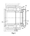
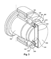
- FIG. 2 and FIG. 3 cross-sectional and perspective views, respectively, are shown of one embodiment of a device for heating a first angular contact inner race or a second angular contact inner race of an angular contact ball bearing mounted on a shaft 202.
- the device for heating the first angular contact inner race or the second angular contact inner race of an angular contact ball bearing mounted on a shaft 202 may include a substantially ring shaped quartz halogen lamp 204 having an exposure to the first angular contact inner race 118 or the second angular contact inner race 120, a reflector 206 attached to the quartz halogen lamp 204 for reflecting heat from the quartz halogen lamp 204 towards the first angular contact inner race 118 or the second angular contact inner race 120, and a housing 208 for enclosing the quartz halogen lamp 204 and the reflector 206.
- a lamp diameter of the quartz halogen lamp 204 may substantially match an inner race diameter.
- the device 202 may further include a sleeve 210 for covering the shaft 102.
- the sleeve 210 may be attached to the reflector 206 for holding the quartz halogen lamp 204 over the first angular contact inner race 118 or the second angular contact inner race 120.
- the sleeve 210 may include a first thermally non-conductive material.
- the first thermally non-conductive material may include ceramic, fiberglass, asbestos, stainless steel, epoxy composite, and/or phenolic plastic.
- the reflector 206 may include an inner ring 212 that extends axially to the shaft 102 for reflecting heat away from the shaft 102.
- the reflector 206 may include an outer ring 214 that extends radially to the shaft 102.
- the outer ring 214 may semi-circumferentially cover the quartz halogen lamp 204.
- the reflector 206 may include a thermally reflective material.
- the thermally reflective material may include glass with a mirror coating or metal.
- the device 202 may further include insulation 216 between the housing 208 and the reflector 206 for insulating the quartz halogen lamp 204.
- the insulation may include a second thermally non-conductive material.
- the second thermally non-conductive material may include ceramic, fiberglass, asbestos, stainless steel, epoxy composite, and/or phenolic plastic.
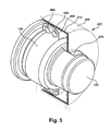
- the device may include at least one substantially ring shaped quartz halogen lamp 404 having an exposure to the roller bearing inner race 108, wherein the exposure is directed radially to the shaft 102, a reflector 406 attached to the at least one quartz halogen lamp 404 for reflecting heat from the quartz halogen lamp 404 towards the roller bearing inner race 108, and a housing 408 for enclosing the quartz halogen lamp 404 and the reflector 406.
- the exposure may be directed radially to the shaft 102.
- the reflector 406 may semi-circumferentially cover the at least one quartz halogen lamp 404.
- the reflector 406 may cover the shaft 102.
- the device 402 may further include a sleeve 410 for covering the shaft 102.
- the sleeve 410 may be attached to the reflector 404 for holding the at least one quartz halogen lamp 404 over the roller bearing inner race 108.
- the sleeve 410 may include a first thermally non-conductive material.
- the first thermally non-conductive material may include ceramic, fiberglass, asbestos, stainless steel, epoxy composite, and/or phenolic plastic.
- the reflector 406 may include a thermally reflective material.
- the thermally reflective material may include glass with a mirror coating or metal.
- the housing 408 may include an opening for receiving an end of the shaft 102.
- the device 402 may further include insulation 412 between the reflector 406 and the at least one quartz halogen lamp 404.
- the insulation 412 may include a second thermally non-conductive material.
- the second thermally non-conductive material may include ceramic, fiberglass, asbestos, stainless steel, epoxy composite, and/or phenolic plastic.
- the embodiments described above and FIGS. 2-5 more specifically describe a broader embodiment of a device for heating an inner race of a bearing arrangement mounted on the shaft.
- the device may include a quartz halogen lamp for heating the inner race and a reflector for reflecting heat from the quartz halogen lamp towards the inner race.
- the device may further include a housing for enclosing the quartz halogen lamp and the reflector.
- the quartz halogen lamp may be substantially ring shaped.
- a lamp diameter of the quartz halogen lamp may substantially match an inner race diameter.
- the device may further include a sleeve for protecting the shaft.
- the sleeve may include a first thermally non-conductive material.
- the first thermally non-conductive material may include ceramic, fiberglass, asbestos, stainless steel, epoxy composite, and/or phenolic plastic.
- the reflector may include a thermally reflective material.
- the thermally reflective material may include glass with a mirror coating or metal.
- the device may further include insulation between the housing and the reflector for insulating the quartz halogen lamp.
- the insulation may include a second thermally non-conductive material.
- the second thermally non-conductive material may include ceramic, fiberglass, asbestos, stainless steel, epoxy composite, and/or phenolic plastic.
Landscapes
- Engineering & Computer Science (AREA)
- General Engineering & Computer Science (AREA)
- Mechanical Engineering (AREA)
- Rolling Contact Bearings (AREA)
- Resistance Heating (AREA)
Abstract
Description
- This invention relates generally to inner races of bearing arrangements and more particularly to a heater for an inner race of a bearing arrangement.
- A bearing arrangement mounted on a shaft may include an angular contact bearing or a roller bearing. Further, more than one bearing may be mounted on the shaft. For example, on an intermediate shaft of a wind turbine, the roller bearing may be placed on an upwind side followed by the angular contact bearing downwind from the roller bearing.
FIG. 1 shows a cross-sectional view of ashaft 102 with the roller bearing 104 and the angular contact bearing 106. A person of ordinary skill in the art will readily recognize that there are many known bearing arrangements. Generally, each known bearing arrangement has an inner race attached to theshaft 102, a rolling element, and an outer race. - The roller bearing 104 may include a roller bearing
inner race 108, aroller 110, and a roller bearingouter race 112. The roller bearinginner race 108 may be of a unitary and cylindrical form. Theroller 110 fits over the roller bearinginner race 108. The roller bearingouter race 112 may be unitary and cylindrical. The roller bearingouter race 112 may include a track 114 for receiving theroller 110 and holding theroller 110 in place. - The angular contact bearing 106 may be separated from the roller bearing 104 by a
spacer ring 116. The angular contact bearing 106 may include a first angular contactinner race 118 and a second angular contactinner race 120, a row ofball bearings 122, and an angular contactouter race 124. The first angular contactinner race 118 may be cylindrical with a first hemi-spherical track 126 to receive the row ofball bearings 122. The second angular contactinner race 120 may be cylindrical with a second hemi-spherical track 128 to receive the row ofball bearings 122. The first and the second angular contactinner races shaft 102 with the first and the second hemi-spherical tracks ball bearings 122 thereby holding the row ofball bearings 122. The angular contactouter race 124 may be cylindrical with a hemi-spherical track 130 to receive the row ofball bearings 122 and hold the row ofball bearings 122 in place. Alocking pin 132 may be included for preventing the angular contactouter race 124 from spinning within the housing. A plurality oflock nuts 134 may hold the first and second angular contactinner races spacer ring 116 and the roller bearinginner race 108 in place in the axial direction. Ashaft cover 136 may enclose the end of theshaft 102. - The installation of the roller bearing
inner race 108 and the first and the second angular contactinner races shaft 102. In order to install them, each of the roller bearinginner race 108 and the first and the second angular contactinner races shaft 102 at its appropriate place. When allowed to cool, the roller bearinginner race 108 and the first and the second angular contactinner races shaft 102 with a considerable holding force. In order to repair or service the angular contact bearing 106, the roller bearing 104, theshaft 102, or any other components of a machine connected to theshaft 102, it may be necessary to remove the roller bearinginner race 108 and the first and the second angular contactinner races inner race 108 or the first or secondangular contact races - A first aspect of the invention provides a device for heating an inner race of a bearing arrangement mounted on a shaft, comprising: a quartz halogen lamp for heating the inner race; and a reflector for reflecting heat from the quartz halogen lamp towards the inner race.
- A second aspect of the invention provides a device for heating a first angular contact inner race or a second angular contact inner race of an angular contact ball bearing mounted on a shaft, comprising: a substantially ring shaped quartz halogen lamp having an exposure to the first angular contact inner race or the second angular contact inner race; a reflector attached to the quartz halogen lamp for reflecting heat from the quartz halogen lamp towards the first angular contact inner race or the second angular contact inner race; and a housing for enclosing the quartz halogen lamp and the reflector.
- A third aspect of the invention provides a device for heating a roller bearing inner race of a roller bearing mounted on a shaft, comprising: at least one substantially ring shaped quartz halogen lamp having an exposure to the roller bearing inner race, wherein the exposure is directed radially to the shaft; a reflector attached to the at least one quartz halogen lamp for reflecting heat from the quartz halogen lamp towards the roller bearing inner race; and a housing for enclosing the quartz halogen lamp and the reflector.
- These and other aspects, advantages and salient features of the invention will become apparent from the following detailed description, which, when taken in conjunction with the annexed drawings, where like parts are designated by like reference characters throughout the drawings, disclose embodiments of the invention.
- The above and other aspects, features and advantages of the invention will be better understood by reading the following more particular description of the invention in conjunction with the accompanying drawings.
-
FIG. 1 shows a cross-section view of a known shaft with a roller bearing and an angular contact bearing. -
FIG. 2 shows a cross-section view of a device for heating a first angular contact inner race or a second angular contact inner race of an angular contact ball bearing in accordance with the present invention. -
FIG. 3 shows a perspective view of a device for heating a first angular contact inner race or a second angular contact inner race of an angular contact ball bearing in accordance with the present invention. -
FIG. 4 shows a cross-section view of a device for heating a roller bearing inner race of a roller bearing in accordance with the present invention. -
FIG. 5 shows a perspective view of a device for heating a roller bearing inner race of a roller bearing in accordance with the present invention. - The drawings are not necessarily to scale. The drawings are merely schematic representations, not intended to portray specific parameters of the invention. The drawings are intended to depict only typical embodiments of the invention, and therefore should not be considered as limiting the scope of the invention. In the drawings, like numbering represents like elements.
- Referring to
FIG. 2 andFIG. 3 , cross-sectional and perspective views, respectively, are shown of one embodiment of a device for heating a first angular contact inner race or a second angular contact inner race of an angular contact ball bearing mounted on ashaft 202. The device for heating the first angular contact inner race or the second angular contact inner race of an angular contact ball bearing mounted on ashaft 202 may include a substantially ring shapedquartz halogen lamp 204 having an exposure to the first angular contactinner race 118 or the second angular contactinner race 120, areflector 206 attached to thequartz halogen lamp 204 for reflecting heat from thequartz halogen lamp 204 towards the first angular contactinner race 118 or the second angular contactinner race 120, and ahousing 208 for enclosing thequartz halogen lamp 204 and thereflector 206. A lamp diameter of thequartz halogen lamp 204 may substantially match an inner race diameter. Thedevice 202 may further include asleeve 210 for covering theshaft 102. Thesleeve 210 may be attached to thereflector 206 for holding thequartz halogen lamp 204 over the first angular contactinner race 118 or the second angular contactinner race 120. Thesleeve 210 may include a first thermally non-conductive material. The first thermally non-conductive material may include ceramic, fiberglass, asbestos, stainless steel, epoxy composite, and/or phenolic plastic. Thereflector 206 may include aninner ring 212 that extends axially to theshaft 102 for reflecting heat away from theshaft 102. Thereflector 206 may include anouter ring 214 that extends radially to theshaft 102. Theouter ring 214 may semi-circumferentially cover thequartz halogen lamp 204. Thereflector 206 may include a thermally reflective material. The thermally reflective material may include glass with a mirror coating or metal. Thedevice 202 may further includeinsulation 216 between thehousing 208 and thereflector 206 for insulating thequartz halogen lamp 204. The insulation may include a second thermally non-conductive material. The second thermally non-conductive material may include ceramic, fiberglass, asbestos, stainless steel, epoxy composite, and/or phenolic plastic. - Referring to
FIG. 4 andFIG. 5 , cross-sectional and perspective views, respectively, are shown of one embodiment of a device for heating a roller bearing inner race of a roller bearing mounted on ashaft 402. The device may include at least one substantially ring shapedquartz halogen lamp 404 having an exposure to the roller bearinginner race 108, wherein the exposure is directed radially to theshaft 102, areflector 406 attached to the at least onequartz halogen lamp 404 for reflecting heat from thequartz halogen lamp 404 towards the roller bearinginner race 108, and ahousing 408 for enclosing thequartz halogen lamp 404 and thereflector 406. The exposure may be directed radially to theshaft 102. Thereflector 406 may semi-circumferentially cover the at least onequartz halogen lamp 404. Thereflector 406 may cover theshaft 102. Thedevice 402 may further include asleeve 410 for covering theshaft 102. Thesleeve 410 may be attached to thereflector 404 for holding the at least onequartz halogen lamp 404 over the roller bearinginner race 108. Thesleeve 410 may include a first thermally non-conductive material. The first thermally non-conductive material may include ceramic, fiberglass, asbestos, stainless steel, epoxy composite, and/or phenolic plastic. Thereflector 406 may include a thermally reflective material. The thermally reflective material may include glass with a mirror coating or metal. Thehousing 408 may include an opening for receiving an end of theshaft 102. Thedevice 402 may further includeinsulation 412 between thereflector 406 and the at least onequartz halogen lamp 404. Theinsulation 412 may include a second thermally non-conductive material. The second thermally non-conductive material may include ceramic, fiberglass, asbestos, stainless steel, epoxy composite, and/or phenolic plastic. - The embodiments described above and
FIGS. 2-5 more specifically describe a broader embodiment of a device for heating an inner race of a bearing arrangement mounted on the shaft. The device may include a quartz halogen lamp for heating the inner race and a reflector for reflecting heat from the quartz halogen lamp towards the inner race. The device may further include a housing for enclosing the quartz halogen lamp and the reflector. The quartz halogen lamp may be substantially ring shaped. A lamp diameter of the quartz halogen lamp may substantially match an inner race diameter. The device may further include a sleeve for protecting the shaft. The sleeve may include a first thermally non-conductive material. The first thermally non-conductive material may include ceramic, fiberglass, asbestos, stainless steel, epoxy composite, and/or phenolic plastic. The reflector may include a thermally reflective material. The thermally reflective material may include glass with a mirror coating or metal. The device may further include insulation between the housing and the reflector for insulating the quartz halogen lamp. The insulation may include a second thermally non-conductive material. The second thermally non-conductive material may include ceramic, fiberglass, asbestos, stainless steel, epoxy composite, and/or phenolic plastic. - The terminology used herein is for the purpose of describing particular embodiments only and is not intended to be limiting of the disclosure. As used herein, the singular forms "a", "an" and "the" are intended to include the plural forms as well, unless the context clearly indicates otherwise. It will be further understood that the terms "comprises" and/or "comprising," when used in this specification, specify the presence of stated features, integers, steps, operations, elements, and/or components, but do not preclude the presence or addition of one or more other features, integers, steps, operations, elements, components, and/or groups thereof.
- While various embodiments are described herein, it will be appreciated from the specification that various combinations of elements, variations or improvements therein may be made by those skilled in the art, and are within the scope of the invention. In addition, many modifications may be made to adapt a particular situation or material to the teachings of the invention without departing from essential scope thereof. Therefore, it is intended that the invention not be limited to the particular embodiment disclosed as the best mode contemplated for carrying out this invention, but that the invention will include all embodiments falling within the scope of the appended claims.
- Various aspects and embodiments of the present invention are defined by the following numbered clauses:
- 1. A device for heating an inner race of a bearing arrangement mounted on a shaft, comprising:
- a quartz halogen lamp for heating the inner race; and
- a reflector for reflecting heat from the quartz halogen lamp towards the inner race.
- 2. The device of clause 1, further comprising:
- a housing for enclosing the quartz halogen lamp and the reflector.
- 3. The device of any preceding clause, wherein the quartz halogen lamp is substantially ring shaped.
- 4. The device of any preceding clause, wherein the diameter of the quartz halogen lamp substantially matches a diameter of the inner race.
- 5. The device of any preceding clause, further comprising:
- a sleeve for protecting the shaft.
- 6. The device of any preceding clause, wherein the sleeve includes a first thermally non-conductive material.
- 7. The device of any preceding clause, wherein the reflector includes a thermally reflective material.
- 8. The device of any preceding clause, further comprising:
- insulation between the housing and the reflector for insulating the quartz halogen lamp.
- 9. The device of any preceding clause, wherein the insulation includes a second thermally non-conductive material.
- 10. A device for heating a first angular contact inner race or a second angular contact inner race of an angular contact ball bearing mounted on a shaft, comprising:
- a substantially ring shaped quartz halogen lamp having an exposure to the first angular contact inner race or the second angular contact inner race;
- a reflector attached to the quartz halogen lamp for reflecting heat from the quartz halogen lamp towards the first angular contact inner race or the second angular contact inner race; and
- a housing for enclosing the quartz halogen lamp and the reflector.
- 11. The device of any preceding clause, further comprising:
- a sleeve covering a shaft, the sleeve attached to the reflector for holding the quartz halogen lamp over the first angular contact inner race or the second angular contact inner race.
- 12. The device of any preceding clause, wherein the reflector reflects heat away from the shaft.
- 13. The device of any preceding clause, wherein the reflector includes an inner ring that extends axially to the shaft for reflecting heat away from the shaft.
- 14. The device of any preceding clause, wherein the reflector includes an outer ring that extends radially to the shaft.
- 15. The device of any preceding clause, wherein the outer ring semi-circumferentially covers the quartz halogen lamp.
- 16. A device for heating a roller bearing inner race of a roller bearing mounted on a shaft, comprising:
- at least one substantially ring shaped quartz halogen lamp having an exposure to the roller bearing inner race, wherein the exposure is directed radially to the shaft;
- a reflector attached to the at least one quartz halogen lamp for reflecting heat from the quartz halogen lamp towards the roller bearing inner race; and
- a housing for enclosing the quartz halogen lamp and the reflector.
- 17. The device of any preceding clause, wherein the reflector semi-circumferentially covers the at least one quartz halogen lamp.
- 18. The device of any preceding clause, wherein the reflector covers the shaft.
- 19. The device of any preceding clause, wherein the housing includes an opening for receiving an end of the shaft.
- 20. The device of any preceding clause, further comprising:
- insulation between the reflector and the at least one quartz halogen lamp.
Claims (15)
- A device for heating an inner race (108; 118, 120) of a bearing arrangement mounted on a shaft (102, 202), comprising:a quartz halogen lamp (204) for heating the inner race; anda reflector (206) for reflecting heat from the quartz halogen lamp (204) towards the inner race.
- The device of claim 1, further comprising:a housing (208) for enclosing the quartz halogen lamp (204) and the reflector (206.
- The device of claim 1 or claim 2, wherein the quartz halogen lamp (204) is substantially ring shaped, wherein, preferably, the diameter of the quartz halogen lamp (204) substantially matches a diameter of the inner race.
- The device of claim 1, 2 or 3, further comprising:a sleeve (210) for protecting the shaft (102), wherein, preferably, the sleeve (210) includes a first thermally non-conductive material.
- The device of any preceding claim, wherein the reflector (206) includes a thermally reflective material.
- The device of any preceding claim, further comprising:insulation (412) between the housing (408) and the reflector (406) for insulating the quartz halogen lamp (404), wherein, preferably, the insulation (412) includes a second thermally non-conductive material.
- A device for heating a first angular contact inner race (118) or a second angular contact inner race (120) of an angular contact ball bearing mounted on a shaft (102; 202), comprising:a substantially ring shaped quartz halogen lamp (204) having an exposure to the first angular contact inner race (118) or the second angular contact inner race (120);a reflector (206) attached to the quartz halogen lamp (204) for reflecting heat from the quartz halogen lamp (204) towards the first angular contact inner race (118) or the second angular contact inner race (120); anda housing (208) for enclosing the quartz halogen lamp (204) and the reflector (206).
- The device of claim 7, further comprising:a sleeve (210) covering a shaft (102), the sleeve (210) attached to the reflector (206) for holding the quartz halogen lamp (204) over the first angular contact inner race (118) or the second angular contact inner race (120).
- The device of claim 8, wherein:the reflector (206) reflects heat away from the shaft (202), and/orthe reflector (206) includes an inner ring (212) that extends axially to the shaft (202) for reflecting heat away from the shaft (202).
- The device of claim 8 or claim 9, wherein the reflector (206) includes an outer ring (214) that extends radially to the shaft (202), wherein, preferably, the outer ring (214) semi-circumferentially covers the quartz halogen lamp (204).
- A device for heating a roller bearing inner race (108) of a roller bearing mounted on a shaft (102; 402), comprising:at least one substantially ring shaped quartz halogen lamp (404) having an exposure to the roller bearing inner race (108), wherein the exposure is directed radially to the shaft (402);a reflector (406) attached to the at least one quartz halogen lamp (404) for reflecting heat from the quartz halogen lamp (404) towards the roller bearing inner race (108); anda housing (408) for enclosing the quartz halogen lamp (404) and the reflector (406).
- The device of claim 11, wherein the reflector (406) semi-circumferentially covers the at least one quartz halogen lamp (404).
- The device of claim 12, wherein the reflector (406) covers the shaft (402).
- The device of claim 12 or claim 13, wherein the housing (408) includes an opening for receiving an end of the shaft (402).
- The device of claim 12, 13 or 14, further comprising:insulation (412) between the reflector (406) and the at least one quartz halogen lamp (404).
Applications Claiming Priority (1)
| Application Number | Priority Date | Filing Date | Title |
|---|---|---|---|
| US13/828,100 US9036987B2 (en) | 2013-03-14 | 2013-03-14 | Bearing arrangement inner race heater |
Publications (3)
| Publication Number | Publication Date |
|---|---|
| EP2778450A2 true EP2778450A2 (en) | 2014-09-17 |
| EP2778450A3 EP2778450A3 (en) | 2017-12-06 |
| EP2778450B1 EP2778450B1 (en) | 2019-01-02 |
Family
ID=50280173
Family Applications (1)
| Application Number | Title | Priority Date | Filing Date |
|---|---|---|---|
| EP14159342.6A Not-in-force EP2778450B1 (en) | 2013-03-14 | 2014-03-13 | Bearing arrangement inner race heater |
Country Status (2)
| Country | Link |
|---|---|
| US (1) | US9036987B2 (en) |
| EP (1) | EP2778450B1 (en) |
Families Citing this family (3)
| Publication number | Priority date | Publication date | Assignee | Title |
|---|---|---|---|---|
| EP2888494A4 (en) * | 2012-08-21 | 2016-05-11 | Skf Publ Ab | WIND TURRET ROTOR ASSEMBLY COMPRISING AN EXPANSION FASTENING PART |
| US10919135B2 (en) * | 2018-03-21 | 2021-02-16 | Saudi Arabian Oil Company | Systems and methods for steam ring heating for bearing removal from shaft |
| US11614078B2 (en) * | 2020-10-26 | 2023-03-28 | General Electric Company | Spherical journal bearing for a wind turbine drivetrain |
Family Cites Families (23)
| Publication number | Priority date | Publication date | Assignee | Title |
|---|---|---|---|---|
| US2042855A (en) * | 1933-12-01 | 1936-06-02 | Merklein William Andrew | Electric heater |
| US2054669A (en) * | 1934-11-21 | 1936-09-15 | Walter G Bunzl | Infrared ray reflector lamp |
| US2505200A (en) * | 1946-01-16 | 1950-04-25 | Isaac A Paige | Combination heater and cooking stove |
| US2748247A (en) * | 1953-04-10 | 1956-05-29 | Wiegand Co Edwin L | Infrared device |
| US3427434A (en) * | 1966-07-15 | 1969-02-11 | Wilson C Gassaway | Bearing heater |
| US3805019A (en) * | 1972-08-24 | 1974-04-16 | Gte Automatic Electric Lab Inc | Energy distribution system |
| US4119834A (en) * | 1976-07-23 | 1978-10-10 | Joseph D. Losch | Electrical radiant heat food warmer and organizer |
| FR2532783A1 (en) * | 1982-09-07 | 1984-03-09 | Vu Duy Phach | THERMAL PROCESSING MACHINE FOR SEMICONDUCTORS |
| USD303832S (en) * | 1987-05-22 | 1989-10-03 | Cone Mounter Company | Thermal expansion heater for bearings |
| GB8725599D0 (en) * | 1987-11-02 | 1987-12-09 | British Aerospace | Heat source |
| JPH08216261A (en) * | 1995-02-13 | 1996-08-27 | Sekisui Chem Co Ltd | Method for joining thermoplastic resin pipes |
| US6400899B1 (en) * | 2000-09-27 | 2002-06-04 | Delphi Technologies, Inc. | Ring assembly manufacturing apparatus and method |
| US6526227B2 (en) * | 2001-02-27 | 2003-02-25 | Ic Tech Co., Ltd. | Radiant electric heater |
| CA2351698A1 (en) * | 2001-06-26 | 2002-12-26 | Green-Line Products Inc. | Radiant energy device for shrinking a thin film |
| US7013080B1 (en) | 2001-08-13 | 2006-03-14 | The W. B. Marvin Manufacturing Company | Space heater with area light source |
| KR200271704Y1 (en) * | 2002-01-08 | 2002-04-10 | (주)솔라텍 | Electric heater with prevention plate on back-reflection dome |
| US6810205B2 (en) | 2003-02-03 | 2004-10-26 | The W. B. Marvin Manufacturing Company | Space heater and light source |
| US20090004032A1 (en) * | 2007-03-29 | 2009-01-01 | Ebara International Corporation | Deswirl mechanisms and roller bearings in an axial thrust equalization mechanism for liquid cryogenic turbomachinery |
| BRPI0823105B1 (en) * | 2007-11-30 | 2020-11-17 | Aktiebolaget Skf | method for heating a bearing element bearing |
| KR20090017682A (en) * | 2008-09-10 | 2009-02-18 | 이진희 | Two way heating cooker |
| US8129662B2 (en) | 2009-01-06 | 2012-03-06 | Reliable Products International | Portable heater |
| CN101913053B (en) * | 2010-08-20 | 2012-05-30 | 常州宝隆冶金设备制造有限公司 | Method and device for quickly and simply disassembling bearing inner ring |
| US8910512B2 (en) * | 2012-03-22 | 2014-12-16 | Kobe Steel, Ltd. | Multi-component force measurement spindle unit of tire testing machine |
-
2013
- 2013-03-14 US US13/828,100 patent/US9036987B2/en active Active
-
2014
- 2014-03-13 EP EP14159342.6A patent/EP2778450B1/en not_active Not-in-force
Non-Patent Citations (1)
| Title |
|---|
| None |
Also Published As
| Publication number | Publication date |
|---|---|
| US20140270737A1 (en) | 2014-09-18 |
| US9036987B2 (en) | 2015-05-19 |
| EP2778450B1 (en) | 2019-01-02 |
| EP2778450A3 (en) | 2017-12-06 |
Similar Documents
| Publication | Publication Date | Title |
|---|---|---|
| US9816526B2 (en) | Wall ring for a fan with heating element | |
| US9664050B2 (en) | Bearings for a turbomachine having an electric motor | |
| EP2778450B1 (en) | Bearing arrangement inner race heater | |
| US5735615A (en) | Insulation arrangement for electrical machine shaft bearing | |
| EP2391820B1 (en) | A wind turbine | |
| CN105464897B (en) | Wind turbine rotor shaft arrangement | |
| JP2016185063A (en) | Stator assembly and magnetic bearing or electric motor having such stator assembly | |
| US9212700B1 (en) | High efficiency and durable ball bearing system with reduced turbine end heat transfer | |
| US20050257522A1 (en) | Turbocharger | |
| US20110014036A1 (en) | Heat shield and turbocharger having a heat shield | |
| CN105889316B (en) | Bearing device | |
| JP2009174528A (en) | Centering the parts inside the shaft | |
| US20130113324A1 (en) | Tapered rotor assembly | |
| RU2013120940A (en) | CONNECTING MODULE BETWEEN THE DRIVE SHAFT OF THE ENGINE OF THE ENGINE AND THE ROLLING BEARING | |
| RU2012147582A (en) | OPEN AIR SCREW FOR TURBO MACHINE | |
| CN1554144A (en) | Wind power generator | |
| RU2696620C2 (en) | Device for passing electric bundle into gas turbine engine | |
| CN103715862A (en) | Mechanical assemblies | |
| RU2015128021A (en) | CENTERING DEVICE FOR ASSEMBLING THE TURBOREACTIVE ENGINE GONDOLA | |
| RU2015141100A (en) | ENGINE INSULATION TEST CASE FOR A GAS TURBINE ENGINE AT A TEST BENCH | |
| GB2499707A (en) | Lubricant flow guiding arrangement for rotor of turbomachine | |
| EP3880968B1 (en) | Vacuum pump | |
| WO2010083907A3 (en) | Method for producing a magnetic system comprising a pole wheel | |
| JP6550947B2 (en) | Rotating machine | |
| CN107061369A (en) | Deicing nose for the low pressure compressor of axial-flow turbine engine |
Legal Events
| Date | Code | Title | Description |
|---|---|---|---|
| 17P | Request for examination filed |
Effective date: 20140313 |
|
| AK | Designated contracting states |
Kind code of ref document: A2 Designated state(s): AL AT BE BG CH CY CZ DE DK EE ES FI FR GB GR HR HU IE IS IT LI LT LU LV MC MK MT NL NO PL PT RO RS SE SI SK SM TR |
|
| AX | Request for extension of the european patent |
Extension state: BA ME |
|
| PUAI | Public reference made under article 153(3) epc to a published international application that has entered the european phase |
Free format text: ORIGINAL CODE: 0009012 |
|
| PUAL | Search report despatched |
Free format text: ORIGINAL CODE: 0009013 |
|
| AK | Designated contracting states |
Kind code of ref document: A3 Designated state(s): AL AT BE BG CH CY CZ DE DK EE ES FI FR GB GR HR HU IE IS IT LI LT LU LV MC MK MT NL NO PL PT RO RS SE SI SK SM TR |
|
| AX | Request for extension of the european patent |
Extension state: BA ME |
|
| RIC1 | Information provided on ipc code assigned before grant |
Ipc: F16C 33/58 20060101ALI20171102BHEP Ipc: F16C 41/00 20060101AFI20171102BHEP Ipc: F16C 35/06 20060101ALI20171102BHEP |
|
| STAA | Information on the status of an ep patent application or granted ep patent |
Free format text: STATUS: REQUEST FOR EXAMINATION WAS MADE |
|
| R17P | Request for examination filed (corrected) |
Effective date: 20180606 |
|
| RBV | Designated contracting states (corrected) |
Designated state(s): AL AT BE BG CH CY CZ DE DK EE ES FI FR GB GR HR HU IE IS IT LI LT LU LV MC MK MT NL NO PL PT RO RS SE SI SK SM TR |
|
| GRAP | Despatch of communication of intention to grant a patent |
Free format text: ORIGINAL CODE: EPIDOSNIGR1 |
|
| STAA | Information on the status of an ep patent application or granted ep patent |
Free format text: STATUS: GRANT OF PATENT IS INTENDED |
|
| INTG | Intention to grant announced |
Effective date: 20180725 |
|
| RIN1 | Information on inventor provided before grant (corrected) |
Inventor name: NEUMANN, ULRICH WARNER |
|
| GRAS | Grant fee paid |
Free format text: ORIGINAL CODE: EPIDOSNIGR3 |
|
| GRAA | (expected) grant |
Free format text: ORIGINAL CODE: 0009210 |
|
| STAA | Information on the status of an ep patent application or granted ep patent |
Free format text: STATUS: THE PATENT HAS BEEN GRANTED |
|
| AK | Designated contracting states |
Kind code of ref document: B1 Designated state(s): AL AT BE BG CH CY CZ DE DK EE ES FI FR GB GR HR HU IE IS IT LI LT LU LV MC MK MT NL NO PL PT RO RS SE SI SK SM TR |
|
| REG | Reference to a national code |
Ref country code: GB Ref legal event code: FG4D |
|
| REG | Reference to a national code |
Ref country code: CH Ref legal event code: EP Ref country code: AT Ref legal event code: REF Ref document number: 1084756 Country of ref document: AT Kind code of ref document: T Effective date: 20190115 |
|
| REG | Reference to a national code |
Ref country code: IE Ref legal event code: FG4D |
|
| REG | Reference to a national code |
Ref country code: DE Ref legal event code: R096 Ref document number: 602014038959 Country of ref document: DE |
|
| REG | Reference to a national code |
Ref country code: NL Ref legal event code: MP Effective date: 20190102 |
|
| REG | Reference to a national code |
Ref country code: LT Ref legal event code: MG4D |
|
| REG | Reference to a national code |
Ref country code: AT Ref legal event code: MK05 Ref document number: 1084756 Country of ref document: AT Kind code of ref document: T Effective date: 20190102 |
|
| PG25 | Lapsed in a contracting state [announced via postgrant information from national office to epo] |
Ref country code: NL Free format text: LAPSE BECAUSE OF FAILURE TO SUBMIT A TRANSLATION OF THE DESCRIPTION OR TO PAY THE FEE WITHIN THE PRESCRIBED TIME-LIMIT Effective date: 20190102 |
|
| PG25 | Lapsed in a contracting state [announced via postgrant information from national office to epo] |
Ref country code: PT Free format text: LAPSE BECAUSE OF FAILURE TO SUBMIT A TRANSLATION OF THE DESCRIPTION OR TO PAY THE FEE WITHIN THE PRESCRIBED TIME-LIMIT Effective date: 20190502 Ref country code: SE Free format text: LAPSE BECAUSE OF FAILURE TO SUBMIT A TRANSLATION OF THE DESCRIPTION OR TO PAY THE FEE WITHIN THE PRESCRIBED TIME-LIMIT Effective date: 20190102 Ref country code: FI Free format text: LAPSE BECAUSE OF FAILURE TO SUBMIT A TRANSLATION OF THE DESCRIPTION OR TO PAY THE FEE WITHIN THE PRESCRIBED TIME-LIMIT Effective date: 20190102 Ref country code: PL Free format text: LAPSE BECAUSE OF FAILURE TO SUBMIT A TRANSLATION OF THE DESCRIPTION OR TO PAY THE FEE WITHIN THE PRESCRIBED TIME-LIMIT Effective date: 20190102 Ref country code: NO Free format text: LAPSE BECAUSE OF FAILURE TO SUBMIT A TRANSLATION OF THE DESCRIPTION OR TO PAY THE FEE WITHIN THE PRESCRIBED TIME-LIMIT Effective date: 20190402 Ref country code: ES Free format text: LAPSE BECAUSE OF FAILURE TO SUBMIT A TRANSLATION OF THE DESCRIPTION OR TO PAY THE FEE WITHIN THE PRESCRIBED TIME-LIMIT Effective date: 20190102 Ref country code: LT Free format text: LAPSE BECAUSE OF FAILURE TO SUBMIT A TRANSLATION OF THE DESCRIPTION OR TO PAY THE FEE WITHIN THE PRESCRIBED TIME-LIMIT Effective date: 20190102 |
|
| PG25 | Lapsed in a contracting state [announced via postgrant information from national office to epo] |
Ref country code: GR Free format text: LAPSE BECAUSE OF FAILURE TO SUBMIT A TRANSLATION OF THE DESCRIPTION OR TO PAY THE FEE WITHIN THE PRESCRIBED TIME-LIMIT Effective date: 20190403 Ref country code: HR Free format text: LAPSE BECAUSE OF FAILURE TO SUBMIT A TRANSLATION OF THE DESCRIPTION OR TO PAY THE FEE WITHIN THE PRESCRIBED TIME-LIMIT Effective date: 20190102 Ref country code: LV Free format text: LAPSE BECAUSE OF FAILURE TO SUBMIT A TRANSLATION OF THE DESCRIPTION OR TO PAY THE FEE WITHIN THE PRESCRIBED TIME-LIMIT Effective date: 20190102 Ref country code: IS Free format text: LAPSE BECAUSE OF FAILURE TO SUBMIT A TRANSLATION OF THE DESCRIPTION OR TO PAY THE FEE WITHIN THE PRESCRIBED TIME-LIMIT Effective date: 20190502 Ref country code: BG Free format text: LAPSE BECAUSE OF FAILURE TO SUBMIT A TRANSLATION OF THE DESCRIPTION OR TO PAY THE FEE WITHIN THE PRESCRIBED TIME-LIMIT Effective date: 20190402 Ref country code: RS Free format text: LAPSE BECAUSE OF FAILURE TO SUBMIT A TRANSLATION OF THE DESCRIPTION OR TO PAY THE FEE WITHIN THE PRESCRIBED TIME-LIMIT Effective date: 20190102 |
|
| REG | Reference to a national code |
Ref country code: DE Ref legal event code: R119 Ref document number: 602014038959 Country of ref document: DE |
|
| REG | Reference to a national code |
Ref country code: DE Ref legal event code: R097 Ref document number: 602014038959 Country of ref document: DE |
|
| PG25 | Lapsed in a contracting state [announced via postgrant information from national office to epo] |
Ref country code: SK Free format text: LAPSE BECAUSE OF FAILURE TO SUBMIT A TRANSLATION OF THE DESCRIPTION OR TO PAY THE FEE WITHIN THE PRESCRIBED TIME-LIMIT Effective date: 20190102 Ref country code: IT Free format text: LAPSE BECAUSE OF FAILURE TO SUBMIT A TRANSLATION OF THE DESCRIPTION OR TO PAY THE FEE WITHIN THE PRESCRIBED TIME-LIMIT Effective date: 20190102 Ref country code: RO Free format text: LAPSE BECAUSE OF FAILURE TO SUBMIT A TRANSLATION OF THE DESCRIPTION OR TO PAY THE FEE WITHIN THE PRESCRIBED TIME-LIMIT Effective date: 20190102 Ref country code: EE Free format text: LAPSE BECAUSE OF FAILURE TO SUBMIT A TRANSLATION OF THE DESCRIPTION OR TO PAY THE FEE WITHIN THE PRESCRIBED TIME-LIMIT Effective date: 20190102 Ref country code: CZ Free format text: LAPSE BECAUSE OF FAILURE TO SUBMIT A TRANSLATION OF THE DESCRIPTION OR TO PAY THE FEE WITHIN THE PRESCRIBED TIME-LIMIT Effective date: 20190102 Ref country code: AT Free format text: LAPSE BECAUSE OF FAILURE TO SUBMIT A TRANSLATION OF THE DESCRIPTION OR TO PAY THE FEE WITHIN THE PRESCRIBED TIME-LIMIT Effective date: 20190102 Ref country code: AL Free format text: LAPSE BECAUSE OF FAILURE TO SUBMIT A TRANSLATION OF THE DESCRIPTION OR TO PAY THE FEE WITHIN THE PRESCRIBED TIME-LIMIT Effective date: 20190102 Ref country code: DK Free format text: LAPSE BECAUSE OF FAILURE TO SUBMIT A TRANSLATION OF THE DESCRIPTION OR TO PAY THE FEE WITHIN THE PRESCRIBED TIME-LIMIT Effective date: 20190102 Ref country code: MC Free format text: LAPSE BECAUSE OF FAILURE TO SUBMIT A TRANSLATION OF THE DESCRIPTION OR TO PAY THE FEE WITHIN THE PRESCRIBED TIME-LIMIT Effective date: 20190102 |
|
| REG | Reference to a national code |
Ref country code: CH Ref legal event code: PL |
|
| PLBE | No opposition filed within time limit |
Free format text: ORIGINAL CODE: 0009261 |
|
| STAA | Information on the status of an ep patent application or granted ep patent |
Free format text: STATUS: NO OPPOSITION FILED WITHIN TIME LIMIT |
|
| PG25 | Lapsed in a contracting state [announced via postgrant information from national office to epo] |
Ref country code: SM Free format text: LAPSE BECAUSE OF FAILURE TO SUBMIT A TRANSLATION OF THE DESCRIPTION OR TO PAY THE FEE WITHIN THE PRESCRIBED TIME-LIMIT Effective date: 20190102 Ref country code: LU Free format text: LAPSE BECAUSE OF NON-PAYMENT OF DUE FEES Effective date: 20190313 |
|
| REG | Reference to a national code |
Ref country code: BE Ref legal event code: MM Effective date: 20190331 |
|
| 26N | No opposition filed |
Effective date: 20191003 |
|
| GBPC | Gb: european patent ceased through non-payment of renewal fee |
Effective date: 20190402 |
|
| PG25 | Lapsed in a contracting state [announced via postgrant information from national office to epo] |
Ref country code: IE Free format text: LAPSE BECAUSE OF NON-PAYMENT OF DUE FEES Effective date: 20190313 Ref country code: DE Free format text: LAPSE BECAUSE OF NON-PAYMENT OF DUE FEES Effective date: 20191001 Ref country code: CH Free format text: LAPSE BECAUSE OF NON-PAYMENT OF DUE FEES Effective date: 20190331 Ref country code: GB Free format text: LAPSE BECAUSE OF NON-PAYMENT OF DUE FEES Effective date: 20190402 Ref country code: LI Free format text: LAPSE BECAUSE OF NON-PAYMENT OF DUE FEES Effective date: 20190331 |
|
| PG25 | Lapsed in a contracting state [announced via postgrant information from national office to epo] |
Ref country code: SI Free format text: LAPSE BECAUSE OF FAILURE TO SUBMIT A TRANSLATION OF THE DESCRIPTION OR TO PAY THE FEE WITHIN THE PRESCRIBED TIME-LIMIT Effective date: 20190102 Ref country code: FR Free format text: LAPSE BECAUSE OF NON-PAYMENT OF DUE FEES Effective date: 20190331 Ref country code: BE Free format text: LAPSE BECAUSE OF NON-PAYMENT OF DUE FEES Effective date: 20190331 |
|
| PG25 | Lapsed in a contracting state [announced via postgrant information from national office to epo] |
Ref country code: TR Free format text: LAPSE BECAUSE OF FAILURE TO SUBMIT A TRANSLATION OF THE DESCRIPTION OR TO PAY THE FEE WITHIN THE PRESCRIBED TIME-LIMIT Effective date: 20190102 |
|
| PG25 | Lapsed in a contracting state [announced via postgrant information from national office to epo] |
Ref country code: MT Free format text: LAPSE BECAUSE OF NON-PAYMENT OF DUE FEES Effective date: 20190313 |
|
| PG25 | Lapsed in a contracting state [announced via postgrant information from national office to epo] |
Ref country code: CY Free format text: LAPSE BECAUSE OF FAILURE TO SUBMIT A TRANSLATION OF THE DESCRIPTION OR TO PAY THE FEE WITHIN THE PRESCRIBED TIME-LIMIT Effective date: 20190102 |
|
| PG25 | Lapsed in a contracting state [announced via postgrant information from national office to epo] |
Ref country code: HU Free format text: LAPSE BECAUSE OF FAILURE TO SUBMIT A TRANSLATION OF THE DESCRIPTION OR TO PAY THE FEE WITHIN THE PRESCRIBED TIME-LIMIT; INVALID AB INITIO Effective date: 20140313 |
|
| PG25 | Lapsed in a contracting state [announced via postgrant information from national office to epo] |
Ref country code: MK Free format text: LAPSE BECAUSE OF FAILURE TO SUBMIT A TRANSLATION OF THE DESCRIPTION OR TO PAY THE FEE WITHIN THE PRESCRIBED TIME-LIMIT Effective date: 20190102 |