EP2778441B1 - Fastening device, in particular for lighting devices - Google Patents
Fastening device, in particular for lighting devices Download PDFInfo
- Publication number
- EP2778441B1 EP2778441B1 EP13172164.9A EP13172164A EP2778441B1 EP 2778441 B1 EP2778441 B1 EP 2778441B1 EP 13172164 A EP13172164 A EP 13172164A EP 2778441 B1 EP2778441 B1 EP 2778441B1
- Authority
- EP
- European Patent Office
- Prior art keywords
- strap
- clip
- fastening device
- clip member
- receiving portion
- Prior art date
- Legal status (The legal status is an assumption and is not a legal conclusion. Google has not performed a legal analysis and makes no representation as to the accuracy of the status listed.)
- Active
Links
Images
Classifications
-
- F—MECHANICAL ENGINEERING; LIGHTING; HEATING; WEAPONS; BLASTING
- F16—ENGINEERING ELEMENTS AND UNITS; GENERAL MEASURES FOR PRODUCING AND MAINTAINING EFFECTIVE FUNCTIONING OF MACHINES OR INSTALLATIONS; THERMAL INSULATION IN GENERAL
- F16B—DEVICES FOR FASTENING OR SECURING CONSTRUCTIONAL ELEMENTS OR MACHINE PARTS TOGETHER, e.g. NAILS, BOLTS, CIRCLIPS, CLAMPS, CLIPS OR WEDGES; JOINTS OR JOINTING
- F16B2/00—Friction-grip releasable fastenings
- F16B2/20—Clips, i.e. with gripping action effected solely by the inherent resistance to deformation of the material of the fastening
- F16B2/22—Clips, i.e. with gripping action effected solely by the inherent resistance to deformation of the material of the fastening of resilient material, e.g. rubbery material
-
- F—MECHANICAL ENGINEERING; LIGHTING; HEATING; WEAPONS; BLASTING
- F21—LIGHTING
- F21L—LIGHTING DEVICES OR SYSTEMS THEREOF, BEING PORTABLE OR SPECIALLY ADAPTED FOR TRANSPORTATION
- F21L4/00—Electric lighting devices with self-contained electric batteries or cells
-
- F—MECHANICAL ENGINEERING; LIGHTING; HEATING; WEAPONS; BLASTING
- F21—LIGHTING
- F21V—FUNCTIONAL FEATURES OR DETAILS OF LIGHTING DEVICES OR SYSTEMS THEREOF; STRUCTURAL COMBINATIONS OF LIGHTING DEVICES WITH OTHER ARTICLES, NOT OTHERWISE PROVIDED FOR
- F21V21/00—Supporting, suspending, or attaching arrangements for lighting devices; Hand grips
- F21V21/08—Devices for easy attachment to any desired place, e.g. clip, clamp, magnet
- F21V21/0816—Strap fasteners, e.g. fasteners with a buckle
-
- F—MECHANICAL ENGINEERING; LIGHTING; HEATING; WEAPONS; BLASTING
- F21—LIGHTING
- F21V—FUNCTIONAL FEATURES OR DETAILS OF LIGHTING DEVICES OR SYSTEMS THEREOF; STRUCTURAL COMBINATIONS OF LIGHTING DEVICES WITH OTHER ARTICLES, NOT OTHERWISE PROVIDED FOR
- F21V21/00—Supporting, suspending, or attaching arrangements for lighting devices; Hand grips
- F21V21/08—Devices for easy attachment to any desired place, e.g. clip, clamp, magnet
- F21V21/088—Clips; Clamps
-
- F—MECHANICAL ENGINEERING; LIGHTING; HEATING; WEAPONS; BLASTING
- F21—LIGHTING
- F21V—FUNCTIONAL FEATURES OR DETAILS OF LIGHTING DEVICES OR SYSTEMS THEREOF; STRUCTURAL COMBINATIONS OF LIGHTING DEVICES WITH OTHER ARTICLES, NOT OTHERWISE PROVIDED FOR
- F21V21/00—Supporting, suspending, or attaching arrangements for lighting devices; Hand grips
- F21V21/08—Devices for easy attachment to any desired place, e.g. clip, clamp, magnet
- F21V21/088—Clips; Clamps
- F21V21/0885—Clips; Clamps for portable lighting devices
-
- F—MECHANICAL ENGINEERING; LIGHTING; HEATING; WEAPONS; BLASTING
- F16—ENGINEERING ELEMENTS AND UNITS; GENERAL MEASURES FOR PRODUCING AND MAINTAINING EFFECTIVE FUNCTIONING OF MACHINES OR INSTALLATIONS; THERMAL INSULATION IN GENERAL
- F16B—DEVICES FOR FASTENING OR SECURING CONSTRUCTIONAL ELEMENTS OR MACHINE PARTS TOGETHER, e.g. NAILS, BOLTS, CIRCLIPS, CLAMPS, CLIPS OR WEDGES; JOINTS OR JOINTING
- F16B2/00—Friction-grip releasable fastenings
- F16B2/02—Clamps, i.e. with gripping action effected by positive means other than the inherent resistance to deformation of the material of the fastening
- F16B2/06—Clamps, i.e. with gripping action effected by positive means other than the inherent resistance to deformation of the material of the fastening external, i.e. with contracting action
- F16B2/08—Clamps, i.e. with gripping action effected by positive means other than the inherent resistance to deformation of the material of the fastening external, i.e. with contracting action using bands
Definitions
- the present invention relates to a fastening device, and in particular to a fastening device for a lighting device.
- fastening devices Numerous types of fastening devices are known, usable to fasten one object to another.
- US 8,360,597 discloses a light mounting apparatus including suitable connection structures to a light source in order to allow multiple degrees of freedom to allow for versatile usage.
- a light source may be attached via a bracket assembly.
- EP 1 010 380 B1 describes a multi-attachment device for use on backpacks, including a base which may be attached to a strap and a releasable catch mechanism. A variety of implement holders can be attached to the base.
- US 6,206,543 B1 describes a flashlight holder assembly for releasably receiving a flashlight of a faceted exterior surface.
- the holder defines a barrel support which is secured to a base.
- the barrel support defines an interior surface and a slot which cooperates to closely receive the exterior surface of the barrel of the flashlight.
- the slot permits the expansion of the exterior surface to accommodate the barrel of the flashlight, thus creating a retaining force on the flashlight barrel when inserted therein.
- the base includes a clip extending from a base plate.
- the clip defines an S-shape configuration and includes a receptor opening.
- the flashlight holder assembly may be mounted on a crossbar or bicycle handlebars, where the receptor opening is large enough to accommodate the crossbar.
- the fastening device includes a clip with a first and second clip member.
- the clip may serve to clamp an object resiliently between the clip members.
- the clip members may be resiliently separable, e. g. at least the second clip member may be resiliently pivotable relative to the first clip member. This may be achieved e.g. by a joint provided between the clip members with a spring element biasing the second clip member towards the first clip member.
- the resilient clamping is achieved by providing at least a portion of the first or second clip member, or a connection portion between the first and second clip member, to be flexible.
- the fastening device further comprises a flexible strap.
- the clip may comprise a strap holding portion, where a first portion of the flexible strap is held within the strap holding portion.
- the holding portion may advantageously be shaped to at least partially surround the first portion of the strap.
- the clip further comprises a strap receiving portion.
- the strap receiving portion may be arranged at distance from the strap holding portion.
- the strap receiving portion may be shaped to receive a second portion of the strap, which is distant from the first portion.
- the strap receiving portion may be provided hook-shaped to engage the second portion of the strap.
- the fastening device may be fixed to another object by clamping within the clip.
- the fastening device according to the invention is thus very flexible and may be fastened to different objects.
- the fastening device may advantageously be used for a plurality of items, and in particular for bicycle accessories.
- An example of an item which may be fastened by the fastening device is a reflector which reflects light and allows better visibility at night time, and which may be fastened e. g. to a bicycle by the strap or to a backpack by the clip.
- a lighting device which may alternatively be fastened to a part of a vehicle, such as e.g. a bar or tube of a bicycle by using the strap, or to a flat object, such as a textile article, an article of clothing, a belt, bag etc. by using the clip.
- the first and second clip members may be formed integrally in one piece.
- the clip including the first and second clip members may be made in one piece out of plastic material, but other materials are possible that provide a sufficient degree of elasticity. The shape and material will thus be chosen to allow the required flexibility for resilient clamping.
- the strap holding portion is provided between the first and second clip members.
- the strap holding portion at a connecting portion which connects the first and second clip member, in particular arranged opposite to the opening between the first and second clip members.
- the strap may be securely held, while the length of the clip members may serve to provide a distance between the strap holding portion and strap receiving portion.
- the second clip member may comprise a portion of concave shape.
- the receiving portion is preferably arranged on the back surface of the second clip member i.e. opposite to the surface of the second clip member facing the first clip member.
- the receiving portion allows to accommodate a tube, bar or other object to which the fastening device may be fastened with the strap.
- the concave shape is preferably rounded so that the fastening device may be attached to an object of round, e.g. circular shape by the strap, in particular to a tube or bar of a bicycle.
- the strap may be of elongate shape and may comprise at least two longitudinal bars arranged at a distance from each other.
- the longitudinal bars of the strap may be arranged at least substantially in parallel.
- at least a first and a second traverse bar may be provided connecting the longitudinal bars of the strap.
- the traverse bars may extend straight, e.g. at right angles to the longitudinal bars. Alternatively, the traverse bars may have bent shape.
- a first traverse bar may be used to fix the strap to the clip by providing the first traverse bar to be received within the strap holding portion. Further, the strap receiving portion maybe shaped to receive a second traverse bar.
- the strap may comprise further traverse bars, e.g. to have at least three or more traverse bars, so that different traverse bars may be used to engage the strap receiving portion, and the fastening device may thus be fastened to objects such as tubes and bars of different diameter.
- the strap may be made out of suitable flexible materials, e.g. rubber, silicone etc. It is preferred to provide the strap including the above described longitudinal and traverse bars in one piece.
- a lighting assembly including a lighting device and a fastening device as describe above.
- the lighting device may e.g. comprise a battery, which may be rechargeable, and an electric light source, such as one or more light emitting diodes (LED).
- LED light emitting diodes
- the clip integrally formed with a housing of the lighting device.
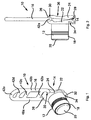
- Figure 1 shows in a perspective view an embodiment of a lighting assembly 10 including a lighting device 12, a clip 14 and a flexible strap 16.
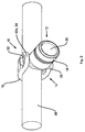
- the lighting assembly 10 may be used as a bicycle light, where the lighting device 12 may be fixed to a tube, bar or other part of a bicycle by means of the flexible strap 16, e. g. as shown in figure 3 .
- the lighting assembly 10 may also be attached to an article of clothing, belt, a bag etc. by using the clip 14.
- the actual lighting device 12 comprises a housing 18, in this example of circular cylindrical shape and made out of aluminium.
- a reflector 20 Arranged at the front side of the housing is a reflector 20 with an LED-element (not shown) behind a transparent cover.
- a battery Within the housing 18, a battery is arranged.
- the transparent cover of the reflector 20 is axially movable against a spring (not shown) to serve as an on/off push button to activate or deactivate the LED-element.
- the clip 14 is made of a single piece of plastic and comprises two clip members 22, 24 oriented roughly in parallel, of which a first clip member 22 has an integrally formed fixing portion of cylindrical shape partially projecting into the housing 18. In this way, the lighting device 12 is fixed to the first clip member.
- the clip 14 further comprises a second clip member 24 connected to the first clip member by a connecting portion 26.
- the entire clip 14 is made out of a plastic material in one piece. Due to the elastic properties of the material, the second clip member 24 is resiliently pivotable with respect to the first clip member 22. Thus, with the application of an opening force, the clip 14 may be opened at an opening 28 such that the ends of the first and second clip members 22, 24 are forced apart.
- a flat object e. g. a belt, textile article etc. may be inserted in the opening 28 of the clip and be clamped between the first and second clip members 22, 24.
- the connecting portion 26 between the first and second clip members 22, 24 forms an inner cavity acting as a strap holding portion 30.
- the strap holding portion 30 surrounds the strap 16 around more than 180°, and close to 240° around its circumference, and therefore grips the strap 16 in form-fitting manner.
- the strap 16 may only be removed from the strap holding portion 30 by compressing the flexible material thereof. Thus, the strap 16 will not be accidentally detached from the clip 14.
- a hook-shaped end of the first clip member 22 forms a strap receiving portion 32.
- the strap receiving portion 32 forms a partially enclosed cavity 34 which may receive a portion of the strap 16.
- the second clip member 24 comprises on its back surface, i. e. facing away from the first clip member 22, a concave bent receiving portion.
- the strap 16 as shown in figure 1 , is formed out of one piece of a flexible material, such as rubber, silicone, etc. It comprises two longitudinal bars 40a, 40b arranged in parallel and connected by five traverse bars 42a, 42b, 42c, 42d, 42e connecting the longitudinal bars 40a, 40b. A first traverse bar 40a is received in the strap holding portion 30.
- the strap 16 is bent around the tube 38.
- the strap fixed to the clip 14 by the first traverse bar 42a received within the strap holding portion 30 is engaged at its opposite end with a fifth traverse bar 42e received within the cavity 34 of the strap receiving portion 32.
- the strap 16 is bent around the bar 38 under tension, and thus attaches the clip 14 to the tube 38.
- the lighting assembly 10 may be fixed to tubes of different diameter by engaging other traverse bars 42c, 42d with the strap receiving portion 32.
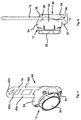
- Figure 4 shows a second embodiment of a lighting assembly.
- the second embodiment resembles in many details the first embodiment, so that in the following only significant differences will be explained, and like parts will be designated by like reference numerals.
- the lighting assembly 50 as shown in figure 4, figure 5 comprises a clip 14, where the second clip member 24, the receiving portion 26 and the strap holding cavity 30 have a similar shape as in the first embodiment.
- the clip 14 comprises a first clip member 52 integrally formed with a back portion of a housing 54 of the lighting device 20.
- the partial housing 54 is integrally formed as one piece of plastic material with the second clip member 24 and connecting portion 26 as well as with the strap engaging portion 32, which is again provided in a hook-shape, with the hook element facing away from the end of the second clip member 24.
- the lighting element 12 comprises a rechargeable battery.
- the housing 54 comprises a charging connector to charge the battery (not shown).
Landscapes
- Engineering & Computer Science (AREA)
- General Engineering & Computer Science (AREA)
- Mechanical Engineering (AREA)
- Non-Portable Lighting Devices Or Systems Thereof (AREA)
- Clamps And Clips (AREA)
Description
- The present invention relates to a fastening device, and in particular to a fastening device for a lighting device.
- Numerous types of fastening devices are known, usable to fasten one object to another.
-
US 8,360,597 discloses a light mounting apparatus including suitable connection structures to a light source in order to allow multiple degrees of freedom to allow for versatile usage. A light source may be attached via a bracket assembly. -
EP 1 010 380 B1 describes a multi-attachment device for use on backpacks, including a base which may be attached to a strap and a releasable catch mechanism. A variety of implement holders can be attached to the base. -
US 6,206,543 B1 describes a flashlight holder assembly for releasably receiving a flashlight of a faceted exterior surface. The holder defines a barrel support which is secured to a base. The barrel support defines an interior surface and a slot which cooperates to closely receive the exterior surface of the barrel of the flashlight. The slot permits the expansion of the exterior surface to accommodate the barrel of the flashlight, thus creating a retaining force on the flashlight barrel when inserted therein. The base includes a clip extending from a base plate. The clip defines an S-shape configuration and includes a receptor opening. The flashlight holder assembly may be mounted on a crossbar or bicycle handlebars, where the receptor opening is large enough to accommodate the crossbar. - It may be considered an object of the invention to provide a fastening device and lighting arrangement allowing flexible fastening.
- The object is solved by a fastening device according to claim 1 and by a lighting assembly according to
claim 12. Dependent claims refer to preferred embodiments. - According to an aspect of the invention, the fastening device includes a clip with a first and second clip member. The clip may serve to clamp an object resiliently between the clip members. To allow this, the clip members may be resiliently separable, e. g. at least the second clip member may be resiliently pivotable relative to the first clip member. This may be achieved e.g. by a joint provided between the clip members with a spring element biasing the second clip member towards the first clip member. Preferably the resilient clamping is achieved by providing at least a portion of the first or second clip member, or a connection portion between the first and second clip member, to be flexible.
- According to one aspect, the fastening device further comprises a flexible strap. The clip may comprise a strap holding portion, where a first portion of the flexible strap is held within the strap holding portion. The holding portion may advantageously be shaped to at least partially surround the first portion of the strap. In particular, it is preferred to provide the strap holding portion to surround the strap for more than 180 degrees around a circumference thereof, so that the first portion of the strap is held in the strap holding portion in form-fitting manner.
- According to a further aspect, the clip further comprises a strap receiving portion. The strap receiving portion may be arranged at distance from the strap holding portion. The strap receiving portion may be shaped to receive a second portion of the strap, which is distant from the first portion.
- In a preferred example, the strap receiving portion may be provided hook-shaped to engage the second portion of the strap.
- By providing a strap holding portion and a strap receiving portion at a distance, it is possible to fasten the device to another object such as a tube, bar etc. by bending the flexible strap around the object and then engaging the second strap portion with the strap receiving portion. Due to the flexible properties of the strap, it may be bent around the object under tension force and can thus be received e.g. in a hook-shaped receiving portion.
- Alternatively, the fastening device may be fixed to another object by clamping within the clip.
- The fastening device according to the invention is thus very flexible and may be fastened to different objects.
- The fastening device may advantageously be used for a plurality of items, and in particular for bicycle accessories. An example of an item which may be fastened by the fastening device is a reflector which reflects light and allows better visibility at night time, and which may be fastened e. g. to a bicycle by the strap or to a backpack by the clip. As will become apparent in connection with preferred embodiments, it is particularly preferred to use the fastening device for a lighting device, which may alternatively be fastened to a part of a vehicle, such as e.g. a bar or tube of a bicycle by using the strap, or to a flat object, such as a textile article, an article of clothing, a belt, bag etc. by using the clip.
- According to a preferred embodiment of the invention, the first and second clip members may be formed integrally in one piece. In particular, the clip including the first and second clip members may be made in one piece out of plastic material, but other materials are possible that provide a sufficient degree of elasticity. The shape and material will thus be chosen to allow the required flexibility for resilient clamping.
- According to one embodiment, the strap holding portion is provided between the first and second clip members. In particular, it is preferred to provide the strap holding portion at a connecting portion which connects the first and second clip member, in particular arranged opposite to the opening between the first and second clip members. In this connecting portion, the strap may be securely held, while the length of the clip members may serve to provide a distance between the strap holding portion and strap receiving portion.
- According to a preferred embodiment of the invention, the second clip member may comprise a portion of concave shape. The receiving portion is preferably arranged on the back surface of the second clip member i.e. opposite to the surface of the second clip member facing the first clip member. The receiving portion allows to accommodate a tube, bar or other object to which the fastening device may be fastened with the strap. The concave shape is preferably rounded so that the fastening device may be attached to an object of round, e.g. circular shape by the strap, in particular to a tube or bar of a bicycle.
- According to a preferred aspect, the strap may be of elongate shape and may comprise at least two longitudinal bars arranged at a distance from each other. The longitudinal bars of the strap may be arranged at least substantially in parallel. Further, at least a first and a second traverse bar may be provided connecting the longitudinal bars of the strap. The traverse bars may extend straight, e.g. at right angles to the longitudinal bars. Alternatively, the traverse bars may have bent shape.
- A first traverse bar may be used to fix the strap to the clip by providing the first traverse bar to be received within the strap holding portion. Further, the strap receiving portion maybe shaped to receive a second traverse bar.
- The strap may comprise further traverse bars, e.g. to have at least three or more traverse bars, so that different traverse bars may be used to engage the strap receiving portion, and the fastening device may thus be fastened to objects such as tubes and bars of different diameter.
- The strap may be made out of suitable flexible materials, e.g. rubber, silicone etc. It is preferred to provide the strap including the above described longitudinal and traverse bars in one piece.
- According to an aspect, a lighting assembly is provided including a lighting device and a fastening device as describe above. The lighting device may e.g. comprise a battery, which may be rechargeable, and an electric light source, such as one or more light emitting diodes (LED).
- In one embodiment, it is preferred to provide the clip integrally formed with a housing of the lighting device.
- These and other aspects of the invention will become apparent from and elucidated with reference to the embodiments describe herein after.
-
- Figure 1
- shows a perspective view of a lighting assembly including a lighting device and a fastening device according to a first embodiment;
- Figure 2
- shows a side-view of the assembly of
figure 1 ; - Figure 3
- shows a perspective view of the assembly of
figure 1, figure 2 mounted on a tube; - Figure 4
- shows a perspective view of a lighting assembly according to a second embodiment;
- Figure 5
- shows a side-view of the assembly according to
figure 4 . -
Figure 1 shows in a perspective view an embodiment of alighting assembly 10 including alighting device 12, aclip 14 and aflexible strap 16. - As will be explained, the
lighting assembly 10 may be used as a bicycle light, where thelighting device 12 may be fixed to a tube, bar or other part of a bicycle by means of theflexible strap 16, e. g. as shown infigure 3 . Alternatively, thelighting assembly 10 may also be attached to an article of clothing, belt, a bag etc. by using theclip 14. - In the first embodiment of a
lighting assembly 10 as shown infigure 1 - 3 , theactual lighting device 12 comprises ahousing 18, in this example of circular cylindrical shape and made out of aluminium. Arranged at the front side of the housing is areflector 20 with an LED-element (not shown) behind a transparent cover. Within thehousing 18, a battery is arranged. The transparent cover of thereflector 20 is axially movable against a spring (not shown) to serve as an on/off push button to activate or deactivate the LED-element. - The
clip 14 is made of a single piece of plastic and comprises twoclip members first clip member 22 has an integrally formed fixing portion of cylindrical shape partially projecting into thehousing 18. In this way, thelighting device 12 is fixed to the first clip member. Theclip 14 further comprises asecond clip member 24 connected to the first clip member by a connectingportion 26. - As explained, the
entire clip 14 is made out of a plastic material in one piece. Due to the elastic properties of the material, thesecond clip member 24 is resiliently pivotable with respect to thefirst clip member 22. Thus, with the application of an opening force, theclip 14 may be opened at anopening 28 such that the ends of the first andsecond clip members opening 28 of the clip and be clamped between the first andsecond clip members - Further, the
strap 16 is attached to theclip 14. The connectingportion 26 between the first andsecond clip members strap holding portion 30. Thestrap holding portion 30 surrounds thestrap 16 around more than 180°, and close to 240° around its circumference, and therefore grips thestrap 16 in form-fitting manner. Thestrap 16 may only be removed from thestrap holding portion 30 by compressing the flexible material thereof. Thus, thestrap 16 will not be accidentally detached from theclip 14. - At the opposite end of the
clip 14, a hook-shaped end of thefirst clip member 22 forms astrap receiving portion 32. As shown, thestrap receiving portion 32 forms a partially enclosedcavity 34 which may receive a portion of thestrap 16. - The
second clip member 24 comprises on its back surface, i. e. facing away from thefirst clip member 22, a concave bent receiving portion. Thus, if thelighting assembly 10 is attached to a tube 38 (figure 3 ), the tube will contact the receivingportion 36, and the bent rounded shape will provide a firm contact. - The
strap 16, as shown infigure 1 , is formed out of one piece of a flexible material, such as rubber, silicone, etc. It comprises twolongitudinal bars traverse bars longitudinal bars first traverse bar 40a is received in thestrap holding portion 30. - As the
lighting assembly 10 is attached to atube 38 as shown infigure 3 , thestrap 16 is bent around thetube 38. The strap fixed to theclip 14 by thefirst traverse bar 42a received within thestrap holding portion 30 is engaged at its opposite end with afifth traverse bar 42e received within thecavity 34 of thestrap receiving portion 32. Thus, thestrap 16 is bent around thebar 38 under tension, and thus attaches theclip 14 to thetube 38. - The
lighting assembly 10 may be fixed to tubes of different diameter by engagingother traverse bars strap receiving portion 32. -
Figure 4 shows a second embodiment of a lighting assembly. The second embodiment resembles in many details the first embodiment, so that in the following only significant differences will be explained, and like parts will be designated by like reference numerals. - The
lighting assembly 50 as shown infigure 4, figure 5 comprises aclip 14, where thesecond clip member 24, the receivingportion 26 and thestrap holding cavity 30 have a similar shape as in the first embodiment. However, theclip 14 comprises afirst clip member 52 integrally formed with a back portion of ahousing 54 of thelighting device 20. Thus, thepartial housing 54 is integrally formed as one piece of plastic material with thesecond clip member 24 and connectingportion 26 as well as with thestrap engaging portion 32, which is again provided in a hook-shape, with the hook element facing away from the end of thesecond clip member 24. - In the second embodiment, the
lighting element 12 comprises a rechargeable battery. Thehousing 54 comprises a charging connector to charge the battery (not shown). - While the invention has been illustrated and described in detail in the drawings and foregoing description, such illustration and description are to be considered illustrative or exemplary and not restrictive; the invention is not limited to the disclosed embodiments.
- Variations from the disclosed embodiments can be understood and effected by those skilled in the art in practicing the claimed invention, from a study of the drawings, the disclosure and the appended claims. In the claims, the word "comprising" does not exclude other elements, and the indefinite articles "a" and/or "an" do not exclude a plurality.
- The mere fact that certain measures are recited in mutually different dependent claims does not indicate that a combination of these measures cannot be used to advantage. Any reference signs in the claims should not be construed as limiting the scope.
Claims (14)
- Fastening device including- a clip (14) with a first clip member (22, 52) and a second clip member (24), where at least said second clip member (24) is resiliently pivotable relative to said first clip member (22, 52) such that a flat object may be resiliently clamped between the first and second clip members (22, 52, 24),
characterized in that- said fastening device further comprises a flexible strap (16),- said clip (14) comprises a strap holding portion (30), wherein a first portion (42a) of said flexible strap (16) is held within said strap holding portion (30),- and wherein said clip (14) further comprises a strap receiving portion (32) arranged at a distance from said strap holding portion (30), said strap receiving portion (32) being shaped to receive a second portion (42e) of said strap (16) distant from said first portion (42a) thereof. - Fastening device according to claim 1, wherein- said first and second clip members (22, 52, 24) are formed integrally in one piece.
- Fastening device according to one of the above claims, wherein- said strap holding portion (30) is shaped to at least partially surround said first portion (42a) of said strap (16).
- Fastening device according to claim 3, wherein- said strap holding portion (30) is shaped to accommodate said first portion (42a) of said strap (16) in form-fitting manner.
- Fastening device according to one of the above claims, further comprising- a fixing portion to mount a lighting device (12), wherein an inner surface of said first clip member (22, 52) is arranged between said fixing portion and said second clip member (24).
- Fastening device according to claim 5, wherein- said fixing portion is a part of a housing (54) of said lighting device (12).
- Fastening device according to one of the above claims, wherein- said second clip member (24) comprises a receiving portion (36),- where said receiving portion (36) has concave shape.
- Fastening device according to one of the above claims, wherein- said strap (16) is of elongate shape comprising at least two longitudinal bars (40), said longitudinal bars (40) being arranged at a distance from each other,- and at least a first and second traverse bar (42a, 42b, 42c, 42d, 42e) connecting said longitudinal bars (40a, 40b),- where said first traverse bar (42a) is received within said strap holding portion (30) and where said strap receiving portion (32) is shaped to receive said second traverse bar (42e).
- Fastening device according to claim 8, wherein- at least three traverse bars are provided connecting said longitudinal bars (40a, 40b).
- Fastening device according to one of the above claims, wherein- said strap receiving portion (32) is arranged on said first clip member (22, 52).
- Fastening device according to one of the above claims, wherein- said strap receiving portion (32) is provided hook-shaped, the open side of the hook facing away from said second clip member (24).
- Lighting assembly, including- a lighting device (12),- and a fastening device (14, 16) according to one of the above claims.
- Lighting assembly according to claim 12, wherein- said clip (14) is integrally formed with a housing (54) at least partially surrounding said lighting device (12).
- Lighting assembly according to claim 12 or 13, wherein- said lighting device (12) comprises at least a battery and an electric light source.
Applications Claiming Priority (1)
| Application Number | Priority Date | Filing Date | Title |
|---|---|---|---|
| US13/840,439 US9476574B2 (en) | 2013-03-15 | 2013-03-15 | Fastening device, in particular for lighting devices |
Publications (2)
| Publication Number | Publication Date |
|---|---|
| EP2778441A1 EP2778441A1 (en) | 2014-09-17 |
| EP2778441B1 true EP2778441B1 (en) | 2016-02-10 |
Family
ID=48746216
Family Applications (1)
| Application Number | Title | Priority Date | Filing Date |
|---|---|---|---|
| EP13172164.9A Active EP2778441B1 (en) | 2013-03-15 | 2013-06-14 | Fastening device, in particular for lighting devices |
Country Status (2)
| Country | Link |
|---|---|
| US (1) | US9476574B2 (en) |
| EP (1) | EP2778441B1 (en) |
Families Citing this family (14)
| Publication number | Priority date | Publication date | Assignee | Title |
|---|---|---|---|---|
| US20150345760A1 (en) * | 2014-05-30 | 2015-12-03 | The Coleman Company, Inc. | Elastic Band Mount for Lighting Device |
| USD768543S1 (en) | 2015-01-05 | 2016-10-11 | Nite Ize, Inc. | Handlebar mount |
| WO2016111927A1 (en) * | 2015-01-05 | 2016-07-14 | Nite Ize, Inc. | Systems and methods for a handlebar interconnector |
| USD876992S1 (en) | 2015-01-05 | 2020-03-03 | Nite Ize, Inc. | Handlebar mounted device holder |
| CN104791669A (en) * | 2015-05-05 | 2015-07-22 | 姜超 | Temporary lighting lamp for dry-mixed mortar mixer |
| USD843035S1 (en) * | 2016-01-03 | 2019-03-12 | Industrial Revolutions, Inc. | Headlamp |
| US20190249848A1 (en) * | 2016-12-16 | 2019-08-15 | Steven Gramling | Enclosure for a lighting device insert |
| DE102020000948A1 (en) * | 2020-02-13 | 2021-08-19 | Andreas Thürk | Portable lighting device |
| US11512840B2 (en) * | 2020-05-19 | 2022-11-29 | Blink Tech LLC | System, apparatus, and method for providing ambient lighting |
| USD1117874S1 (en) * | 2023-05-31 | 2026-03-10 | Nite Ize, Inc. | Bike light |
| US11226075B1 (en) * | 2021-05-25 | 2022-01-18 | AG Lighting Innovations LLC | Lighting system for attachment to tubular structure |
| US11944084B1 (en) * | 2023-09-01 | 2024-04-02 | G. Theodore Norbits | Post mounted item holder |
| US12146651B1 (en) * | 2024-05-31 | 2024-11-19 | Kai Cao | Luminous object combination device and combination method |
| USD1083173S1 (en) * | 2024-07-29 | 2025-07-08 | Hongping Zhang | Pet light head and accessory kit |
Family Cites Families (28)
| Publication number | Priority date | Publication date | Assignee | Title |
|---|---|---|---|---|
| US67393A (en) * | 1867-07-30 | Abraham m | ||
| US4170337A (en) | 1978-05-19 | 1979-10-09 | Davis Milton S | Bicycle accessory |
| US5181774A (en) * | 1992-01-08 | 1993-01-26 | Lee Lane | Lamp bracket |
| US5436810A (en) * | 1992-08-13 | 1995-07-25 | Vistalite, Inc. | Portable headlamp |
| US5325568A (en) * | 1993-06-21 | 1994-07-05 | Ronald Bruhm | Tie-down device combining a looped strap and a snubbing clinch |
| US5778583A (en) * | 1996-07-01 | 1998-07-14 | Bedford Industries, Inc. | Stretchable marking article |
| KR100572526B1 (en) | 1998-12-18 | 2006-04-24 | 내셔날 몰딩 코오포레이션 | Multipurpose Attachment |
| US6206543B1 (en) | 1999-11-12 | 2001-03-27 | David Vincent Henry | Flashlight holder assembly |
| JP2002130218A (en) * | 2000-10-19 | 2002-05-09 | Nifco Inc | Clamp |
| US6618906B2 (en) * | 2001-05-22 | 2003-09-16 | Skeleton Crew Entertainment, Inc. | Device for securing a lighting apparatus to a paintball mask |
| US6575587B2 (en) * | 2001-07-26 | 2003-06-10 | The Coleman Company, Inc. | Light with clamp that fits into a headband |
| US6543094B2 (en) * | 2001-08-30 | 2003-04-08 | J. D'addario & Co., Inc. | Cable management tie wrap |
| US7077302B2 (en) * | 2001-12-10 | 2006-07-18 | Louis Chuang | Apparatus for selectively attaching a first object to a second object in a desired orientation |
| US20030137850A1 (en) * | 2002-01-23 | 2003-07-24 | Shu-Jang Liaw | Light device for bicycles |
| US6749166B2 (en) * | 2002-11-13 | 2004-06-15 | Mike Valentine | Flashlight holder |
| US7168821B2 (en) * | 2004-12-07 | 2007-01-30 | Gem Optical Co., Ltd. | Lens assembly with light mountable on head covering |
| US8545041B2 (en) * | 2004-12-18 | 2013-10-01 | Msb Incorporated | Mounting clip |
| US8070027B2 (en) * | 2005-04-25 | 2011-12-06 | Piatt Sr John A | Adaptable tool hook |
| US20070011850A1 (en) * | 2005-07-15 | 2007-01-18 | Mark Downing | Strap securing device |
| US7070295B1 (en) * | 2005-10-14 | 2006-07-04 | Wen Sung Lee | Light device for attaching to objects |
| US8387939B2 (en) * | 2006-04-20 | 2013-03-05 | The Flewelling Ford Family Trust | Mounting support with light |
| US8360597B1 (en) | 2007-11-01 | 2013-01-29 | Neville Blake Hanchett | Light mounting apparatus |
| US8459912B2 (en) * | 2008-04-24 | 2013-06-11 | Illinois Tool Works Inc. | Tie-down hook |
| JP4996533B2 (en) * | 2008-04-25 | 2012-08-08 | 有限会社クロップス | Small light |
| US7857478B1 (en) * | 2008-09-05 | 2010-12-28 | Marvin Keller | Wearable safety light apparatus |
| US8876340B2 (en) * | 2011-01-03 | 2014-11-04 | Nite Ize, Inc. | Personal lighting device |
| US20120218771A1 (en) * | 2011-02-24 | 2012-08-30 | Yu Chi Yen | Solar power bicycle light assembly cooperated with alkaline battery |
| GB2480553A (en) * | 2011-05-19 | 2011-11-23 | Claire Burley | Carriage device for attaching a scooter to a pushchair handle |
-
2013
- 2013-03-15 US US13/840,439 patent/US9476574B2/en active Active
- 2013-06-14 EP EP13172164.9A patent/EP2778441B1/en active Active
Also Published As
| Publication number | Publication date |
|---|---|
| US9476574B2 (en) | 2016-10-25 |
| US20140268710A1 (en) | 2014-09-18 |
| EP2778441A1 (en) | 2014-09-17 |
Similar Documents
| Publication | Publication Date | Title |
|---|---|---|
| US9476574B2 (en) | Fastening device, in particular for lighting devices | |
| US8733710B1 (en) | Clamp display system | |
| US8545041B2 (en) | Mounting clip | |
| US5154506A (en) | Flashlight armband | |
| US8132764B2 (en) | Quick-release adjustable mounting bracket | |
| US6749166B2 (en) | Flashlight holder | |
| US9174781B2 (en) | Tie wrap for bundling objects | |
| US6105908A (en) | Retainer strap with breakable hinge member | |
| KR100572526B1 (en) | Multipurpose Attachment | |
| US20080111344A1 (en) | Apparatus for attaching accessory to bicycle | |
| FR2996989A1 (en) | HEAVY-DUTY HELMET WITH PERFECTIONED HEADLINER AND JUGULAR | |
| CN104685293A (en) | A holder for holding a carrier, a lighting module, a luminaire and a method of manufacturing a holder for a lighting module | |
| WO2010078585A1 (en) | Accessory holder for handlebars | |
| US20090272775A1 (en) | Implement holder | |
| CN102782402A (en) | Securing strap system for work light | |
| CN101297768A (en) | Handheld device cradle with a substantially semicircular clip assembly and an advertising method | |
| US20160029575A1 (en) | Plant holder for attachment to a rod or a tube | |
| CN118891472A (en) | Portable light holder and related methods | |
| US20090039125A1 (en) | Device for mounting bicycle accessories | |
| JP2006026207A (en) | buckle | |
| WO2008121883A1 (en) | Bicycle light with clip | |
| CN108688982B (en) | Retainer | |
| CN104684796B (en) | Cable tie wraps for binding objects | |
| US8668126B2 (en) | Self wrapped gadget holder for stroller | |
| CA2625570A1 (en) | Body mounted support system for photo and video camera |
Legal Events
| Date | Code | Title | Description |
|---|---|---|---|
| PUAI | Public reference made under article 153(3) epc to a published international application that has entered the european phase |
Free format text: ORIGINAL CODE: 0009012 |
|
| 17P | Request for examination filed |
Effective date: 20130614 |
|
| AK | Designated contracting states |
Kind code of ref document: A1 Designated state(s): AL AT BE BG CH CY CZ DE DK EE ES FI FR GB GR HR HU IE IS IT LI LT LU LV MC MK MT NL NO PL PT RO RS SE SI SK SM TR |
|
| AX | Request for extension of the european patent |
Extension state: BA ME |
|
| R17P | Request for examination filed (corrected) |
Effective date: 20141015 |
|
| RBV | Designated contracting states (corrected) |
Designated state(s): AL AT BE BG CH CY CZ DE DK EE ES FI FR GB GR HR HU IE IS IT LI LT LU LV MC MK MT NL NO PL PT RO RS SE SI SK SM TR |
|
| 17Q | First examination report despatched |
Effective date: 20150317 |
|
| GRAP | Despatch of communication of intention to grant a patent |
Free format text: ORIGINAL CODE: EPIDOSNIGR1 |
|
| INTG | Intention to grant announced |
Effective date: 20150707 |
|
| GRAS | Grant fee paid |
Free format text: ORIGINAL CODE: EPIDOSNIGR3 |
|
| INTG | Intention to grant announced |
Effective date: 20151203 |
|
| GRAA | (expected) grant |
Free format text: ORIGINAL CODE: 0009210 |
|
| AK | Designated contracting states |
Kind code of ref document: B1 Designated state(s): AL AT BE BG CH CY CZ DE DK EE ES FI FR GB GR HR HU IE IS IT LI LT LU LV MC MK MT NL NO PL PT RO RS SE SI SK SM TR |
|
| REG | Reference to a national code |
Ref country code: GB Ref legal event code: FG4D |
|
| REG | Reference to a national code |
Ref country code: AT Ref legal event code: REF Ref document number: 774798 Country of ref document: AT Kind code of ref document: T Effective date: 20160215 Ref country code: CH Ref legal event code: EP |
|
| REG | Reference to a national code |
Ref country code: IE Ref legal event code: FG4D |
|
| REG | Reference to a national code |
Ref country code: DE Ref legal event code: R096 Ref document number: 602013004987 Country of ref document: DE |
|
| REG | Reference to a national code |
Ref country code: LT Ref legal event code: MG4D |
|
| REG | Reference to a national code |
Ref country code: NL Ref legal event code: MP Effective date: 20160210 |
|
| REG | Reference to a national code |
Ref country code: FR Ref legal event code: PLFP Year of fee payment: 4 |
|
| REG | Reference to a national code |
Ref country code: AT Ref legal event code: MK05 Ref document number: 774798 Country of ref document: AT Kind code of ref document: T Effective date: 20160210 |
|
| PG25 | Lapsed in a contracting state [announced via postgrant information from national office to epo] |
Ref country code: ES Free format text: LAPSE BECAUSE OF FAILURE TO SUBMIT A TRANSLATION OF THE DESCRIPTION OR TO PAY THE FEE WITHIN THE PRESCRIBED TIME-LIMIT Effective date: 20160210 Ref country code: FI Free format text: LAPSE BECAUSE OF FAILURE TO SUBMIT A TRANSLATION OF THE DESCRIPTION OR TO PAY THE FEE WITHIN THE PRESCRIBED TIME-LIMIT Effective date: 20160210 Ref country code: GR Free format text: LAPSE BECAUSE OF FAILURE TO SUBMIT A TRANSLATION OF THE DESCRIPTION OR TO PAY THE FEE WITHIN THE PRESCRIBED TIME-LIMIT Effective date: 20160511 Ref country code: NO Free format text: LAPSE BECAUSE OF FAILURE TO SUBMIT A TRANSLATION OF THE DESCRIPTION OR TO PAY THE FEE WITHIN THE PRESCRIBED TIME-LIMIT Effective date: 20160510 Ref country code: IT Free format text: LAPSE BECAUSE OF FAILURE TO SUBMIT A TRANSLATION OF THE DESCRIPTION OR TO PAY THE FEE WITHIN THE PRESCRIBED TIME-LIMIT Effective date: 20160210 Ref country code: HR Free format text: LAPSE BECAUSE OF FAILURE TO SUBMIT A TRANSLATION OF THE DESCRIPTION OR TO PAY THE FEE WITHIN THE PRESCRIBED TIME-LIMIT Effective date: 20160210 |
|
| PG25 | Lapsed in a contracting state [announced via postgrant information from national office to epo] |
Ref country code: PL Free format text: LAPSE BECAUSE OF FAILURE TO SUBMIT A TRANSLATION OF THE DESCRIPTION OR TO PAY THE FEE WITHIN THE PRESCRIBED TIME-LIMIT Effective date: 20160210 Ref country code: PT Free format text: LAPSE BECAUSE OF FAILURE TO SUBMIT A TRANSLATION OF THE DESCRIPTION OR TO PAY THE FEE WITHIN THE PRESCRIBED TIME-LIMIT Effective date: 20160613 Ref country code: LT Free format text: LAPSE BECAUSE OF FAILURE TO SUBMIT A TRANSLATION OF THE DESCRIPTION OR TO PAY THE FEE WITHIN THE PRESCRIBED TIME-LIMIT Effective date: 20160210 Ref country code: SE Free format text: LAPSE BECAUSE OF FAILURE TO SUBMIT A TRANSLATION OF THE DESCRIPTION OR TO PAY THE FEE WITHIN THE PRESCRIBED TIME-LIMIT Effective date: 20160210 Ref country code: IS Free format text: LAPSE BECAUSE OF FAILURE TO SUBMIT A TRANSLATION OF THE DESCRIPTION OR TO PAY THE FEE WITHIN THE PRESCRIBED TIME-LIMIT Effective date: 20160610 Ref country code: NL Free format text: LAPSE BECAUSE OF FAILURE TO SUBMIT A TRANSLATION OF THE DESCRIPTION OR TO PAY THE FEE WITHIN THE PRESCRIBED TIME-LIMIT Effective date: 20160210 Ref country code: LV Free format text: LAPSE BECAUSE OF FAILURE TO SUBMIT A TRANSLATION OF THE DESCRIPTION OR TO PAY THE FEE WITHIN THE PRESCRIBED TIME-LIMIT Effective date: 20160210 Ref country code: AT Free format text: LAPSE BECAUSE OF FAILURE TO SUBMIT A TRANSLATION OF THE DESCRIPTION OR TO PAY THE FEE WITHIN THE PRESCRIBED TIME-LIMIT Effective date: 20160210 Ref country code: RS Free format text: LAPSE BECAUSE OF FAILURE TO SUBMIT A TRANSLATION OF THE DESCRIPTION OR TO PAY THE FEE WITHIN THE PRESCRIBED TIME-LIMIT Effective date: 20160210 |
|
| PG25 | Lapsed in a contracting state [announced via postgrant information from national office to epo] |
Ref country code: EE Free format text: LAPSE BECAUSE OF FAILURE TO SUBMIT A TRANSLATION OF THE DESCRIPTION OR TO PAY THE FEE WITHIN THE PRESCRIBED TIME-LIMIT Effective date: 20160210 Ref country code: DK Free format text: LAPSE BECAUSE OF FAILURE TO SUBMIT A TRANSLATION OF THE DESCRIPTION OR TO PAY THE FEE WITHIN THE PRESCRIBED TIME-LIMIT Effective date: 20160210 |
|
| REG | Reference to a national code |
Ref country code: DE Ref legal event code: R097 Ref document number: 602013004987 Country of ref document: DE |
|
| PG25 | Lapsed in a contracting state [announced via postgrant information from national office to epo] |
Ref country code: SM Free format text: LAPSE BECAUSE OF FAILURE TO SUBMIT A TRANSLATION OF THE DESCRIPTION OR TO PAY THE FEE WITHIN THE PRESCRIBED TIME-LIMIT Effective date: 20160210 Ref country code: RO Free format text: LAPSE BECAUSE OF FAILURE TO SUBMIT A TRANSLATION OF THE DESCRIPTION OR TO PAY THE FEE WITHIN THE PRESCRIBED TIME-LIMIT Effective date: 20160210 Ref country code: SK Free format text: LAPSE BECAUSE OF FAILURE TO SUBMIT A TRANSLATION OF THE DESCRIPTION OR TO PAY THE FEE WITHIN THE PRESCRIBED TIME-LIMIT Effective date: 20160210 Ref country code: CZ Free format text: LAPSE BECAUSE OF FAILURE TO SUBMIT A TRANSLATION OF THE DESCRIPTION OR TO PAY THE FEE WITHIN THE PRESCRIBED TIME-LIMIT Effective date: 20160210 |
|
| PLBE | No opposition filed within time limit |
Free format text: ORIGINAL CODE: 0009261 |
|
| STAA | Information on the status of an ep patent application or granted ep patent |
Free format text: STATUS: NO OPPOSITION FILED WITHIN TIME LIMIT |
|
| PG25 | Lapsed in a contracting state [announced via postgrant information from national office to epo] |
Ref country code: BE Free format text: LAPSE BECAUSE OF FAILURE TO SUBMIT A TRANSLATION OF THE DESCRIPTION OR TO PAY THE FEE WITHIN THE PRESCRIBED TIME-LIMIT Effective date: 20160210 |
|
| 26N | No opposition filed |
Effective date: 20161111 |
|
| PG25 | Lapsed in a contracting state [announced via postgrant information from national office to epo] |
Ref country code: MC Free format text: LAPSE BECAUSE OF FAILURE TO SUBMIT A TRANSLATION OF THE DESCRIPTION OR TO PAY THE FEE WITHIN THE PRESCRIBED TIME-LIMIT Effective date: 20160210 |
|
| REG | Reference to a national code |
Ref country code: CH Ref legal event code: PL |
|
| PG25 | Lapsed in a contracting state [announced via postgrant information from national office to epo] |
Ref country code: BG Free format text: LAPSE BECAUSE OF FAILURE TO SUBMIT A TRANSLATION OF THE DESCRIPTION OR TO PAY THE FEE WITHIN THE PRESCRIBED TIME-LIMIT Effective date: 20160510 Ref country code: SI Free format text: LAPSE BECAUSE OF FAILURE TO SUBMIT A TRANSLATION OF THE DESCRIPTION OR TO PAY THE FEE WITHIN THE PRESCRIBED TIME-LIMIT Effective date: 20160210 |
|
| REG | Reference to a national code |
Ref country code: IE Ref legal event code: MM4A |
|
| PG25 | Lapsed in a contracting state [announced via postgrant information from national office to epo] |
Ref country code: LI Free format text: LAPSE BECAUSE OF NON-PAYMENT OF DUE FEES Effective date: 20160630 Ref country code: CH Free format text: LAPSE BECAUSE OF NON-PAYMENT OF DUE FEES Effective date: 20160630 |
|
| PG25 | Lapsed in a contracting state [announced via postgrant information from national office to epo] |
Ref country code: IE Free format text: LAPSE BECAUSE OF NON-PAYMENT OF DUE FEES Effective date: 20160614 |
|
| REG | Reference to a national code |
Ref country code: FR Ref legal event code: PLFP Year of fee payment: 5 |
|
| PG25 | Lapsed in a contracting state [announced via postgrant information from national office to epo] |
Ref country code: HU Free format text: LAPSE BECAUSE OF FAILURE TO SUBMIT A TRANSLATION OF THE DESCRIPTION OR TO PAY THE FEE WITHIN THE PRESCRIBED TIME-LIMIT; INVALID AB INITIO Effective date: 20130614 |
|
| REG | Reference to a national code |
Ref country code: FR Ref legal event code: PLFP Year of fee payment: 6 |
|
| PG25 | Lapsed in a contracting state [announced via postgrant information from national office to epo] |
Ref country code: MK Free format text: LAPSE BECAUSE OF FAILURE TO SUBMIT A TRANSLATION OF THE DESCRIPTION OR TO PAY THE FEE WITHIN THE PRESCRIBED TIME-LIMIT Effective date: 20160210 Ref country code: CY Free format text: LAPSE BECAUSE OF FAILURE TO SUBMIT A TRANSLATION OF THE DESCRIPTION OR TO PAY THE FEE WITHIN THE PRESCRIBED TIME-LIMIT Effective date: 20160210 Ref country code: LU Free format text: LAPSE BECAUSE OF NON-PAYMENT OF DUE FEES Effective date: 20160614 Ref country code: MT Free format text: LAPSE BECAUSE OF NON-PAYMENT OF DUE FEES Effective date: 20160630 |
|
| PG25 | Lapsed in a contracting state [announced via postgrant information from national office to epo] |
Ref country code: AL Free format text: LAPSE BECAUSE OF FAILURE TO SUBMIT A TRANSLATION OF THE DESCRIPTION OR TO PAY THE FEE WITHIN THE PRESCRIBED TIME-LIMIT Effective date: 20160210 Ref country code: TR Free format text: LAPSE BECAUSE OF FAILURE TO SUBMIT A TRANSLATION OF THE DESCRIPTION OR TO PAY THE FEE WITHIN THE PRESCRIBED TIME-LIMIT Effective date: 20160210 |
|
| PGFP | Annual fee paid to national office [announced via postgrant information from national office to epo] |
Ref country code: DE Payment date: 20250625 Year of fee payment: 13 |
|
| PGFP | Annual fee paid to national office [announced via postgrant information from national office to epo] |
Ref country code: GB Payment date: 20250620 Year of fee payment: 13 |
|
| PGFP | Annual fee paid to national office [announced via postgrant information from national office to epo] |
Ref country code: FR Payment date: 20250626 Year of fee payment: 13 |