EP2778385A1 - Fuel injection system with multiple valves and fuel injection method thereof - Google Patents
Fuel injection system with multiple valves and fuel injection method thereof Download PDFInfo
- Publication number
- EP2778385A1 EP2778385A1 EP20110875135 EP11875135A EP2778385A1 EP 2778385 A1 EP2778385 A1 EP 2778385A1 EP 20110875135 EP20110875135 EP 20110875135 EP 11875135 A EP11875135 A EP 11875135A EP 2778385 A1 EP2778385 A1 EP 2778385A1
- Authority
- EP
- European Patent Office
- Prior art keywords
- electronic
- fuel
- unit pump
- electronic unit
- high pressure
- Prior art date
- Legal status (The legal status is an assumption and is not a legal conclusion. Google has not performed a legal analysis and makes no representation as to the accuracy of the status listed.)
- Granted
Links
Images



Classifications
-
- F—MECHANICAL ENGINEERING; LIGHTING; HEATING; WEAPONS; BLASTING
- F02—COMBUSTION ENGINES; HOT-GAS OR COMBUSTION-PRODUCT ENGINE PLANTS
- F02M—SUPPLYING COMBUSTION ENGINES IN GENERAL WITH COMBUSTIBLE MIXTURES OR CONSTITUENTS THEREOF
- F02M59/00—Pumps specially adapted for fuel-injection and not provided for in groups F02M39/00 -F02M57/00, e.g. rotary cylinder-block type of pumps
- F02M59/20—Varying fuel delivery in quantity or timing
- F02M59/36—Varying fuel delivery in quantity or timing by variably-timed valves controlling fuel passages to pumping elements or overflow passages
- F02M59/366—Valves being actuated electrically
-
- F—MECHANICAL ENGINEERING; LIGHTING; HEATING; WEAPONS; BLASTING
- F02—COMBUSTION ENGINES; HOT-GAS OR COMBUSTION-PRODUCT ENGINE PLANTS
- F02D—CONTROLLING COMBUSTION ENGINES
- F02D41/00—Electrical control of supply of combustible mixture or its constituents
- F02D41/30—Controlling fuel injection
- F02D41/38—Controlling fuel injection of the high pressure type
- F02D41/3809—Common rail control systems
- F02D41/3836—Controlling the fuel pressure
- F02D41/3845—Controlling the fuel pressure by controlling the flow into the common rail, e.g. the amount of fuel pumped
-
- F—MECHANICAL ENGINEERING; LIGHTING; HEATING; WEAPONS; BLASTING
- F02—COMBUSTION ENGINES; HOT-GAS OR COMBUSTION-PRODUCT ENGINE PLANTS
- F02D—CONTROLLING COMBUSTION ENGINES
- F02D41/00—Electrical control of supply of combustible mixture or its constituents
- F02D41/30—Controlling fuel injection
- F02D41/38—Controlling fuel injection of the high pressure type
- F02D41/40—Controlling fuel injection of the high pressure type with means for controlling injection timing or duration
- F02D41/401—Controlling injection timing
-
- F—MECHANICAL ENGINEERING; LIGHTING; HEATING; WEAPONS; BLASTING
- F02—COMBUSTION ENGINES; HOT-GAS OR COMBUSTION-PRODUCT ENGINE PLANTS
- F02D—CONTROLLING COMBUSTION ENGINES
- F02D41/00—Electrical control of supply of combustible mixture or its constituents
- F02D41/30—Controlling fuel injection
- F02D41/38—Controlling fuel injection of the high pressure type
- F02D41/40—Controlling fuel injection of the high pressure type with means for controlling injection timing or duration
- F02D41/402—Multiple injections
-
- F—MECHANICAL ENGINEERING; LIGHTING; HEATING; WEAPONS; BLASTING
- F02—COMBUSTION ENGINES; HOT-GAS OR COMBUSTION-PRODUCT ENGINE PLANTS
- F02D—CONTROLLING COMBUSTION ENGINES
- F02D41/00—Electrical control of supply of combustible mixture or its constituents
- F02D41/30—Controlling fuel injection
- F02D41/38—Controlling fuel injection of the high pressure type
- F02D41/40—Controlling fuel injection of the high pressure type with means for controlling injection timing or duration
- F02D41/406—Electrically controlling a diesel injection pump
-
- F—MECHANICAL ENGINEERING; LIGHTING; HEATING; WEAPONS; BLASTING
- F02—COMBUSTION ENGINES; HOT-GAS OR COMBUSTION-PRODUCT ENGINE PLANTS
- F02M—SUPPLYING COMBUSTION ENGINES IN GENERAL WITH COMBUSTIBLE MIXTURES OR CONSTITUENTS THEREOF
- F02M59/00—Pumps specially adapted for fuel-injection and not provided for in groups F02M39/00 -F02M57/00, e.g. rotary cylinder-block type of pumps
- F02M59/02—Pumps specially adapted for fuel-injection and not provided for in groups F02M39/00 -F02M57/00, e.g. rotary cylinder-block type of pumps of reciprocating-piston or reciprocating-cylinder type
- F02M59/025—Pumps specially adapted for fuel-injection and not provided for in groups F02M39/00 -F02M57/00, e.g. rotary cylinder-block type of pumps of reciprocating-piston or reciprocating-cylinder type characterised by a single piston
-
- F—MECHANICAL ENGINEERING; LIGHTING; HEATING; WEAPONS; BLASTING
- F02—COMBUSTION ENGINES; HOT-GAS OR COMBUSTION-PRODUCT ENGINE PLANTS
- F02M—SUPPLYING COMBUSTION ENGINES IN GENERAL WITH COMBUSTIBLE MIXTURES OR CONSTITUENTS THEREOF
- F02M59/00—Pumps specially adapted for fuel-injection and not provided for in groups F02M39/00 -F02M57/00, e.g. rotary cylinder-block type of pumps
- F02M59/02—Pumps specially adapted for fuel-injection and not provided for in groups F02M39/00 -F02M57/00, e.g. rotary cylinder-block type of pumps of reciprocating-piston or reciprocating-cylinder type
- F02M59/10—Pumps specially adapted for fuel-injection and not provided for in groups F02M39/00 -F02M57/00, e.g. rotary cylinder-block type of pumps of reciprocating-piston or reciprocating-cylinder type characterised by the piston-drive
- F02M59/102—Mechanical drive, e.g. tappets or cams
-
- F—MECHANICAL ENGINEERING; LIGHTING; HEATING; WEAPONS; BLASTING
- F02—COMBUSTION ENGINES; HOT-GAS OR COMBUSTION-PRODUCT ENGINE PLANTS
- F02M—SUPPLYING COMBUSTION ENGINES IN GENERAL WITH COMBUSTIBLE MIXTURES OR CONSTITUENTS THEREOF
- F02M63/00—Other fuel-injection apparatus having pertinent characteristics not provided for in groups F02M39/00 - F02M57/00 or F02M67/00; Details, component parts, or accessories of fuel-injection apparatus, not provided for in, or of interest apart from, the apparatus of groups F02M39/00 - F02M61/00 or F02M67/00; Combination of fuel pump with other devices, e.g. lubricating oil pump
- F02M63/02—Fuel-injection apparatus having several injectors fed by a common pumping element, or having several pumping elements feeding a common injector; Fuel-injection apparatus having provisions for cutting-out pumps, pumping elements, or injectors; Fuel-injection apparatus having provisions for variably interconnecting pumping elements and injectors alternatively
-
- F—MECHANICAL ENGINEERING; LIGHTING; HEATING; WEAPONS; BLASTING
- F02—COMBUSTION ENGINES; HOT-GAS OR COMBUSTION-PRODUCT ENGINE PLANTS
- F02M—SUPPLYING COMBUSTION ENGINES IN GENERAL WITH COMBUSTIBLE MIXTURES OR CONSTITUENTS THEREOF
- F02M47/00—Fuel-injection apparatus operated cyclically with fuel-injection valves actuated by fluid pressure
- F02M47/02—Fuel-injection apparatus operated cyclically with fuel-injection valves actuated by fluid pressure of accumulator-injector type, i.e. having fuel pressure of accumulator tending to open, and fuel pressure in other chamber tending to close, injection valves and having means for periodically releasing that closing pressure
- F02M47/027—Electrically actuated valves draining the chamber to release the closing pressure
-
- Y—GENERAL TAGGING OF NEW TECHNOLOGICAL DEVELOPMENTS; GENERAL TAGGING OF CROSS-SECTIONAL TECHNOLOGIES SPANNING OVER SEVERAL SECTIONS OF THE IPC; TECHNICAL SUBJECTS COVERED BY FORMER USPC CROSS-REFERENCE ART COLLECTIONS [XRACs] AND DIGESTS
- Y02—TECHNOLOGIES OR APPLICATIONS FOR MITIGATION OR ADAPTATION AGAINST CLIMATE CHANGE
- Y02T—CLIMATE CHANGE MITIGATION TECHNOLOGIES RELATED TO TRANSPORTATION
- Y02T10/00—Road transport of goods or passengers
- Y02T10/10—Internal combustion engine [ICE] based vehicles
- Y02T10/40—Engine management systems
-
- Y—GENERAL TAGGING OF NEW TECHNOLOGICAL DEVELOPMENTS; GENERAL TAGGING OF CROSS-SECTIONAL TECHNOLOGIES SPANNING OVER SEVERAL SECTIONS OF THE IPC; TECHNICAL SUBJECTS COVERED BY FORMER USPC CROSS-REFERENCE ART COLLECTIONS [XRACs] AND DIGESTS
- Y10—TECHNICAL SUBJECTS COVERED BY FORMER USPC
- Y10T—TECHNICAL SUBJECTS COVERED BY FORMER US CLASSIFICATION
- Y10T137/00—Fluid handling
- Y10T137/0318—Processes
-
- Y—GENERAL TAGGING OF NEW TECHNOLOGICAL DEVELOPMENTS; GENERAL TAGGING OF CROSS-SECTIONAL TECHNOLOGIES SPANNING OVER SEVERAL SECTIONS OF THE IPC; TECHNICAL SUBJECTS COVERED BY FORMER USPC CROSS-REFERENCE ART COLLECTIONS [XRACs] AND DIGESTS
- Y10—TECHNICAL SUBJECTS COVERED BY FORMER USPC
- Y10T—TECHNICAL SUBJECTS COVERED BY FORMER US CLASSIFICATION
- Y10T137/00—Fluid handling
- Y10T137/8593—Systems
- Y10T137/85978—With pump
- Y10T137/85986—Pumped fluid control
- Y10T137/86027—Electric
Definitions
- the present invention relates to fuel injection system.
- it is to an electronically controlled high pressure fuel supply system and a method characterized by ideal fuel supply performance with full range of operating condition.
- the power scope becomes wider, which needs to enlarge the range of fuel injection quantity.
- Large fuel injection means to require large fuel injector nozzle area. Under the condition of small fuel injection quantity or idling, the large fuel injector nozzle can cause relatively large fuel injection error which may lead to speed fluctuation.
- the highly-intensified diesel engine should embrace the real-time flexible adjustable characteristics at the process of high pressure injection so as to improve the dynamic characteristics of the engine.
- the mainstream oil supply system it is a challenge to accurately control the large scope of fuel injection quantity and improve the cycle responding characteristics of the fuel injection system.
- the high pressure common rail fuel supply system can flexibly regulate the fuel injection. But the larger volume of the common rail cavity leads to slower cycle response speed that is unable to regulate injection starting pressure in cycles.
- the electronic unit pump adopts the mode of one cylinder to one pump which accumulates the high pressure only at the injection stage. It can obtain the high injection pressure and enjoy system reliability. But the disadvantages are also obvious: the injection pressure and fuel injection law can not be adjusted, the injection pressure relates with cam speed which cannot match the injection characteristic for high speed and low speed simultaneously. It can be concluded that neither high pressure common rail fuel supply system nor electronic unit pump can meet the large fuel injection scope of the highly-intensified diesel engine and high requirements for the cycle response characteristic.
- the present invention integrates the advantages of both electronic unit pump and high-pressure common rail system. It adopts the structure with one electronic unit pump to multi electronic fuel injectors and provides a new valve fuel system. Based on the fuel supply cam profile of the electronic unit pump and the speed, injection pressure and injection law can be flexibly regulated through adjusting the controlled time sequence of the electronic unit pump and electronic fuel injectors.
- the present invention provides a type of fuel injection system with multiple valves which includes the following components.
- Electronic unit pump which is used to output high pressure fuel.
- Low pressure fuel pipe which is used to input fuel to the pump chamber of electronic unit pump as mentioned.
- Fuel supply cam which is used to push the plunger of the electronic unit pump mentioned above to generate the high pressure fuel.
- At least two electronic fuel injectors for fuel injection At least two electronic fuel injectors for fuel injection.
- High pressure fuel injection pipe which is used to connect the electronic unit pump and electronic fuel injectors as mentioned and make the high pressure fuel outputted by the electronic unit pump flow into the electronic fuel injectors.
- Electronic control unit which is used to connect the electronic unit pump and electronic fuel injectors as mentioned above respectively. It can control the opening and closing of the solenoid valve in the electronic unit pump and electronic fuel injectors as mentioned.
- the present invention also provides a new injection method of fuel injection system with multiple valves including the following components.
- Electronic unit pump which is used to output the high pressure fuel.
- Fuel supply cam which is used to push the plunger motion of the electronic unit pump as mentioned to generate the high pressure fuel.
- Two electronic fuel injectors at least, which are used for fuel injection.
- High pressure injection pipe which is used to connect the electronic unit pump and the electronic fuel injectors as mentioned and make the high pressure fuel outputted by the electronic unit pump flow into the electronic fuel injectors.
- Electronic control unit which is used to connect the electronic unit pump and electronic fuel injectors as mentioned respectively. It can control the opening and closing of the solenoid valve in the electronic unit pump and electronic fuel injectors as mentioned.
- the present injection method includes the following procedures.
- At least one solenoid valve of the electronic fuel injector should be time opening to finish one injection process.
- the present invention has the following advantages: first, the common rail cavity was replaced by the high pressure fuel injection pipe which not only makes the electronic unit pump and electronic fuel injector keep pressure with synchronization but also improves the responding features of the system. Second, in the high pressure fuel injection pipe, there is only instantaneous high pressure, not continuous high pressure, so the reliability of the system can be improved. Third, the quick adjustment of the characteristics of fuel supply in each working cycle can be achieved, which meets the dynamic acceleration characteristics of vehicles. Fourth, the solenoid valves which are used for generating high pressure and injecting fuel are controlled by the electronic control units respectively. According to fuel injection demand, operation timing of solenoid valves and injection pressure are adjusted to generate high pressure at low speed, greatly improve the starting characteristic of liquid fuel engine and reduce emission during starting process. Fifth, under the condition of high load and speed, it can achieve large fuel injection quantity in a short time, so optimizing the combustion process. Sixth, single electronic unit pump supplies fuel to multi-cylinders, which leads to substantial decrease of the system cost.
- FIG.1 is a profile of a preferred embodiment structure of the fuel injection system with multiple valves of this invention.
- FIG.2 is a profile of another preferred embodiment structure of the fuel injection system with multiple valves of this invention.
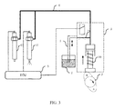
- FIG.3 is a profile of another preferred embodiment structure of the fuel injection system with multiple valves of this invention.
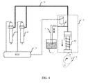
- FIG.4 is a profile of another preferred embodiment structure of the fuel injection system with multiple valves of this invention.
- FIG.5 is a flowchart of a preferred embodiment of the method of fuel injection system with multiple valves of this invention.
- first character above the second character can include not only the direct contact embodiment made by the first and second character but also the embodiment made by other characters between the first character and the second one, so that the first character may not have direct contact with the second character.
- the components are not necessarily to scale and this should be specially noticed.
- the present invention omits the description of the known components and processing technologies to avoid limiting this invention.
- the structure of fuel injection system with multiple valves of the present invention (referring to FIG.1 ) is depicted as follows.
- the fuel injection system with multiple valves includes low pressure fuel circuit 1, fuel supply cam 2, electronic unit pump 3, electronic fuel injector 4, electronic control unit 5 and high pressure injection pipe 6, wherein the electronic unit pump 3 consists of plunger 30 and solenoid valve 31 controlling the low pressure fuel circuit.
- each electronic fuel injector 4 has the solenoid valve which can control fuel injection condition.
- the low pressure fuel pipe 1 is in fluid communication with electronic unit pump 3 and it can make the low pressure fuel flow into the electronic unit pump 3 from tank 7.
- the solenoid valve 31 between the low pressure fuel pipe 1 and electronic unit pump 3 is closed, the fluid communication is cut off.
- the high pressure fuel flows into the electronic fuel injector 4 through high pressure pipe 6.
- electronic control unit 5 can control the operation timing of the electronic fuel injector 4. According to the engine firing sequence and fuel injection timing, electronic control unit 5 chooses electronic fuel injector for fuel injection and the opening commands are sent to the electronic fuel injector 4, then it opens the internal solenoid valve to start the electronic fuel injector 4. At the same time, it can start all the electronic fuel injectors 4, any one or more of them. But in order to ensure the injection pressure of each electronic fuel injectors 4 and the stability of the whole system, it is preferred to allow only one of the electronic fuel injectors to start fuel injection operation at any time.
- the fuel pipe After opening the solenoid valve of the electronic fuel injector 4, the fuel pipe keeps high pressure state and the electronic fuel injector begins to work. When closing the solenoid valve of the electronic fuel injector 4, the fuel injection stops. So the above description is the whole fuel injection process.
- the opening and closing operation timing of the solenoid valves in the electronic unit pump and the corresponding electronic fuel injector the injection timing of the electronic fuel injector and fuel injection duration can be controlled.
- electronic control unit 5 makes the solenoid valve of the electronic fuel injector 4 closed, and the solenoid valve 31 of the electronic unit pump 3 opens, so that the high pressure fuel injection pipe 6, electronic unit pump3 and low pressure fuel pipe 1 are connected and the high pressure fuel in the high pressure injection pipe 6 flows back to the low pressure fuel pipe1.
- the solenoid valve 31 of the electronic unit pump 3 the pressure in the high pressure injection pipe can be reduced.
- the number of convex of cam profile of the fuel supply cam is the same as that of the electronic control injectors. As shown in FIG1 , there are three electronic control injectors, and correspondingly, the cam profile of the fuel supply cam 2 has three convexes.
- the convex of the cam profile has contact with the plunger of the electronic unit pump 3 to drive the plunger to compress the fuel in the plunger chamber. If the solenoid valve 31 of the electronic unit pump 3 is closed, high pressure is established in the high pressure injection pipe. People can enhance the speed ratio of the cam and crankshaft to make one cam match multi-injectors.
- the ratio of the number of the described electronic control injector and the number of cam profile convex of the fuel supply cam is twice as the speed ratio of camshaft and crankshaft
- the ratio of the number of electronic control injector and the number of cam profile convex of the fuel supply cam is the same as the speed ratio of camshaft and crankshaft.
- the speed ratio of cam and crankshaft is 1 to 1
- one convex can match two injectors
- the speed ratio of cam and crankshaft is 2 to 1
- one convex can match four injectors.
- FIG 2 to FIG 4 are schematic diagrams of the specific working process of the fuel injection system with multiple valves.
- the difference between the fuel injection system with multiple valves referring to FIG 2 to FIG 4 and the one referring to FIG1 includes: there are two electronic control injectors: injector 41 and injector 42.
- the cam profile of the fuel supply cam 2 has two convexes: convex A and convex B.
- electronic control unit 5 closes the solenoid valve 31 of the electronic unit pump 3 and cut off the connection between the low pressure fuel pipe 1 and the plunger chamber of the electronic unit pump 3.
- Convex A of the cam profile of the fuel supply cam 2 has contact with the plunger 30 of the electronic unit pump 3 to make the plunger 30 move upward and then compresses the fuel in the plunger chamber to generate high pressure fuel.
- high pressure fuel injection pipe 6 the fuel is sent to electronic control injector 41 and 42.
- the electronic control unit 5 opens the solenoid valve of the electronic control injector 42, then the injector 42 begins to work, and one fuel injection is completed.
- the plunger 30 of the electronic unit pump 3 With the rotating of the fuel supply cam 2, when the convex B of the cam profile of the fuel supply cam 2 has contact with the plunger 30 of the electronic unit pump 3, the plunger 30 is driven to move upward and then compress the fuel in the plunger chamber to generate high pressure fuel. Through high pressure fuel injection pipe 6, the fuel is sent to electronic control injector 41 and 42.
- the electronic control unit 5 opens the solenoid valve of the electronic control injector 41, then injector 41 begins to work, and one fuel injection is completed (referring to FIG3 ).
- multi-closing and multi-opening the solenoid valve of electronic control injector can realize multi-injection for one electronic control injector in a single working course.
- the in-turn fuel injection of multi-injector can be realized in a single working course.
- the low pressure fuel pipe 1 has connection with the plunger chamber of electronic unit pump 3 and begins to feed the fuel in the plunger chamber (referring to FIG.4 ).
- FIG.1 to 4 show that there can be several fuel supply cams and electronic control injectors. It is worth attention that the number of electronic control injector 4 and the number of convex of cam profile of the oil supply cam 2 can be both the same and different.
- FIG 5 is a flow chart of a preferred application mode of the present invention.
- step S101 fuel is inputted to the plunger hole of the electronic unit pump through low pressure fuel pipe.
- the solenoid of the electronic unit pump is open, controlled by the electronic control unit, wherein the low pressure fuel pipe, plunger hole of the electronic unit pump and the fuel injection pipe are connected.
- step S102 when the supply cam pushes the plunger upward and the solenoid of the electronic is closed, cut off the connection between the low pressure fuel pipe and the plunger hole of the electronic unit pump, wherein the plunger is pushed by the supply cam to squeeze the fuel into high pressure and the high pressure fuel is transmitted to electronic injector through injection pipe.
- the plunger hole is inputted with fuel and the solenoid valve between the low pressure fuel pipe and the electronic unit pump is closed, so as to form a confined space with high pressure pipe.
- the volume of the confined space reduced to establish high pressure for the fuel.
- step S103 according to the combustion demand, timed open at least one of the solenoid valve of the electronic control injector, completing one course of injection.
- the high pressure fuel is sent to the electronic control injector by high pressure oil tube.
- the electronic control unit opens at least one solenoid valve of the electronic control injector to complete the injection process.
- One cylinder matches one electronic control injector.
- the aim of multi-emitting in one circulation of the electronic control injector can be realized.
- the electronic control injector emits fuel or not in every cylinder is controlled by electronic control unit, by controlling the opening and closing sequence of the solenoid valve of electronic unit pump and the electronic control injector, independent control of the injection pressure, injection time and injection duration of every electronic control injector can be achieved.
- the solenoid valve of the electronic unit pump could be over-voltage protected.
- the solenoid valve of the claimed electronic unit pump opens and makes the fuel of the fuel injection pipe reflux into oil tank to reduce the pressure of the injection pipe.
- the present invention is described by referring to diesel engine, illustrating the new method of fuel injection system with multiple valves and the specific implementation details.
- the present invention can also applied to other liquid fuel engine, including but not limiting the gasoline engine, oil engine, two DME engine, etc.
- the new multi-valve fuel injection system can meet the need of large scale fuel injection adjusting and quick regulating of the supply fuel performance in cycles.
Landscapes
- Engineering & Computer Science (AREA)
- Chemical & Material Sciences (AREA)
- Combustion & Propulsion (AREA)
- Mechanical Engineering (AREA)
- General Engineering & Computer Science (AREA)
- Fuel-Injection Apparatus (AREA)
Abstract
Description
- The present invention relates to fuel injection system. In detail, it is to an electronically controlled high pressure fuel supply system and a method characterized by ideal fuel supply performance with full range of operating condition.
- With the development of the liquid fuel engine technology, high power density is greatly needed. The higher efficiency of cylinder combustion process can enhance the engine power, wherein the most important factor is to optimize the fuel injection process.
- Taking diesel engine as an example, with the enhancement of the power, the power scope becomes wider, which needs to enlarge the range of fuel injection quantity. Large fuel injection means to require large fuel injector nozzle area. Under the condition of small fuel injection quantity or idling, the large fuel injector nozzle can cause relatively large fuel injection error which may lead to speed fluctuation. However, if we accurately control the fuel injection quantity at the low speed, we will not get the maximum fuel injection. The highly-intensified diesel engine should embrace the real-time flexible adjustable characteristics at the process of high pressure injection so as to improve the dynamic characteristics of the engine. As for the mainstream oil supply system it is a challenge to accurately control the large scope of fuel injection quantity and improve the cycle responding characteristics of the fuel injection system.
- The high pressure common rail fuel supply system can flexibly regulate the fuel injection. But the larger volume of the common rail cavity leads to slower cycle response speed that is unable to regulate injection starting pressure in cycles. The electronic unit pump adopts the mode of one cylinder to one pump which accumulates the high pressure only at the injection stage. It can obtain the high injection pressure and enjoy system reliability. But the disadvantages are also obvious: the injection pressure and fuel injection law can not be adjusted, the injection pressure relates with cam speed which cannot match the injection characteristic for high speed and low speed simultaneously. It can be concluded that neither high pressure common rail fuel supply system nor electronic unit pump can meet the large fuel injection scope of the highly-intensified diesel engine and high requirements for the cycle response characteristic.
- Thus, we need a new type of fuel injection technology to optimize the fuel injection process to solve the above problems.
- The present invention integrates the advantages of both electronic unit pump and high-pressure common rail system. It adopts the structure with one electronic unit pump to multi electronic fuel injectors and provides a new valve fuel system. Based on the fuel supply cam profile of the electronic unit pump and the speed, injection pressure and injection law can be flexibly regulated through adjusting the controlled time sequence of the electronic unit pump and electronic fuel injectors.
- The present invention provides a type of fuel injection system with multiple valves which includes the following components.
- Electronic unit pump, which is used to output high pressure fuel.
- Low pressure fuel pipe, which is used to input fuel to the pump chamber of electronic unit pump as mentioned.
- Fuel supply cam, which is used to push the plunger of the electronic unit pump mentioned above to generate the high pressure fuel.
- At least two electronic fuel injectors for fuel injection.
- High pressure fuel injection pipe. Which is used to connect the electronic unit pump and electronic fuel injectors as mentioned and make the high pressure fuel outputted by the electronic unit pump flow into the electronic fuel injectors.
- Electronic control unit, which is used to connect the electronic unit pump and electronic fuel injectors as mentioned above respectively. It can control the opening and closing of the solenoid valve in the electronic unit pump and electronic fuel injectors as mentioned.
- The present invention also provides a new injection method of fuel injection system with multiple valves including the following components.
- Electronic unit pump, which is used to output the high pressure fuel.
- Low pressure fuel pipe, which is used to input fuel to the pump chamber of electronic unit pump as mentioned
- Fuel supply cam, which is used to push the plunger motion of the electronic unit pump as mentioned to generate the high pressure fuel.
- Two electronic fuel injectors at least, which are used for fuel injection.
- High pressure injection pipe, which is used to connect the electronic unit pump and the electronic fuel injectors as mentioned and make the high pressure fuel outputted by the electronic unit pump flow into the electronic fuel injectors.
- Electronic control unit, which is used to connect the electronic unit pump and electronic fuel injectors as mentioned respectively. It can control the opening and closing of the solenoid valve in the electronic unit pump and electronic fuel injectors as mentioned.
- The present injection method includes the following procedures.
- Input fuel to the pump chamber of the electronic unit pump by the low pressure fuel pipe.
- When the fuel supply cam pushes the plunger of the electronic unit pump to move towards the plunger chamber and the control valve of the electronic unit pump is closed, cut off the connection between the low pressure fuel pipe and the plunger chamber, and the plunger is pushed by the fuel supply cam which extrudes the fuel to get high pressure. In addition, the high pressure fuel flows into the electronic fuel injector through the high pressure injection pipe.
- According to the combustion demand, at least one solenoid valve of the electronic fuel injector should be time opening to finish one injection process.
- The present invention has the following advantages: first, the common rail cavity was replaced by the high pressure fuel injection pipe which not only makes the electronic unit pump and electronic fuel injector keep pressure with synchronization but also improves the responding features of the system. Second, in the high pressure fuel injection pipe, there is only instantaneous high pressure, not continuous high pressure, so the reliability of the system can be improved. Third, the quick adjustment of the characteristics of fuel supply in each working cycle can be achieved, which meets the dynamic acceleration characteristics of vehicles. Fourth, the solenoid valves which are used for generating high pressure and injecting fuel are controlled by the electronic control units respectively. According to fuel injection demand, operation timing of solenoid valves and injection pressure are adjusted to generate high pressure at low speed, greatly improve the starting characteristic of liquid fuel engine and reduce emission during starting process. Fifth, under the condition of high load and speed, it can achieve large fuel injection quantity in a short time, so optimizing the combustion process. Sixth, single electronic unit pump supplies fuel to multi-cylinders, which leads to substantial decrease of the system cost.
- For a more complete understanding of the present disclosure and its advantages, reference is now made to the following description, taken in conjunction with the accompanying drawings, in which:
-
FIG.1 is a profile of a preferred embodiment structure of the fuel injection system with multiple valves of this invention. -
FIG.2 is a profile of another preferred embodiment structure of the fuel injection system with multiple valves of this invention. -
FIG.3 is a profile of another preferred embodiment structure of the fuel injection system with multiple valves of this invention. -
FIG.4 is a profile of another preferred embodiment structure of the fuel injection system with multiple valves of this invention. -
FIG.5 is a flowchart of a preferred embodiment of the method of fuel injection system with multiple valves of this invention. - The identical and similar references represent the identical and similar components in attached drawings
- The following drawings describe the invention in details.
- The drawings display embodiment of the invention, in which the identical and similar signs represent the identical and similar components or components possess the identical and similar functions. The following description of the preferred embodiments is merely exemplary in nature and is in no way intended to limit the invention, its application, or uses.
- The following section provides many different embodiments and examples which describe the different structures of the present invention. In order to simplify the publicity of the invention, the following section describes components and settings of a specific example. In fact, they are only exemplary and their aims are not to limit the invention. Besides, the present disclosure can repeat the reference FIGs and /or letters in different examples. These repetitions are for aims of simplifying and clearing, and they don't express the relationship between embodiments discussed and/ or their settings. Moreover the invention supplies many examples of specific technology and material, but in this field, common technical workers are aware of the application of other technology and/or the usage of other material. In addition, the structures of the first character above the second character can include not only the direct contact embodiment made by the first and second character but also the embodiment made by other characters between the first character and the second one, so that the first character may not have direct contact with the second character. In the drawing the components are not necessarily to scale and this should be specially noticed. The present invention omits the description of the known components and processing technologies to avoid limiting this invention.
- The structure of fuel injection system with multiple valves of the present invention (referring to
FIG.1 ) is depicted as follows. InFIG.1 the fuel injection system with multiple valves includes lowpressure fuel circuit 1,fuel supply cam 2,electronic unit pump 3, electronic fuel injector 4,electronic control unit 5 and highpressure injection pipe 6, wherein theelectronic unit pump 3 consists ofplunger 30 andsolenoid valve 31 controlling the low pressure fuel circuit. Moreover each electronic fuel injector 4 has the solenoid valve which can control fuel injection condition. - One end of the low
pressure fuel circuit 1 connects thetank 7 and the other end reacheselectronic unit pump 3. In most of the cases, the lowpressure fuel pipe 1 is in fluid communication withelectronic unit pump 3 and it can make the low pressure fuel flow into theelectronic unit pump 3 fromtank 7. When thesolenoid valve 31 between the lowpressure fuel pipe 1 andelectronic unit pump 3 is closed, the fluid communication is cut off. - When the
fuel supply cam 2 rotates to a certain angle, the bulge of thefuel supply cam 2 has contact withplunger 30 of theelectronic unit pump 3, driveplunger 30 move upward and extrude the fuel in the plunger chamber. With ceaseless rotation of thefuel supply cam 2, the cam drivesplunger 30 to make reciprocating linear motion and then make the electronic unit pump work. When plunger moves down, the plunger chamber is full of fuel. When the plunger moves up, it squeezes the fuel. Whenplunger 30 moves up and thesolenoid valve 31 is open, with the connectivity of tank, low pressure fuel circuit, plunger chamber and high pressure fuel pipe, the squeezing cannot generate high pressure in the plunger chamber and high pressure pipe. Whenplunger 30 moves up and thesolenoid valve 31 is closed, with the disconnection of high and low pressure fuel pipe, the plunger compresses the enclosed spaces to generate high pressure in the high pressure fuel injection pipe. The opening and closing of thesolenoid valve 31 of theelectronic unit pump 3 is controlled by theelectronic control unit 5. - The high pressure fuel flows into the electronic fuel injector 4 through
high pressure pipe 6. As shown in the FIG,electronic control unit 5 can control the operation timing of the electronic fuel injector 4. According to the engine firing sequence and fuel injection timing,electronic control unit 5 chooses electronic fuel injector for fuel injection and the opening commands are sent to the electronic fuel injector 4, then it opens the internal solenoid valve to start the electronic fuel injector 4. At the same time, it can start all the electronic fuel injectors 4, any one or more of them. But in order to ensure the injection pressure of each electronic fuel injectors 4 and the stability of the whole system, it is preferred to allow only one of the electronic fuel injectors to start fuel injection operation at any time. - After opening the solenoid valve of the electronic fuel injector 4, the fuel pipe keeps high pressure state and the electronic fuel injector begins to work. When closing the solenoid valve of the electronic fuel injector 4, the fuel injection stops. So the above description is the whole fuel injection process. During a working cycle in some cylinder of the engine, by controlling the opening and closing operation timing of the solenoid valves in the electronic unit pump and the corresponding electronic fuel injector, the injection timing of the electronic fuel injector and fuel injection duration can be controlled.
- After the injection finished,
electronic control unit 5 makes the solenoid valve of the electronic fuel injector 4 closed, and thesolenoid valve 31 of theelectronic unit pump 3 opens, so that the high pressurefuel injection pipe 6, electronic unit pump3 and lowpressure fuel pipe 1 are connected and the high pressure fuel in the highpressure injection pipe 6 flows back to the low pressure fuel pipe1. When the high pressure injection pipe is in high pressure, by open thesolenoid valve 31 of theelectronic unit pump 3, the pressure in the high pressure injection pipe can be reduced. - The number of convex of cam profile of the fuel supply cam is the same as that of the electronic control injectors. As shown in
FIG1 , there are three electronic control injectors, and correspondingly, the cam profile of thefuel supply cam 2 has three convexes. The convex of the cam profile has contact with the plunger of theelectronic unit pump 3 to drive the plunger to compress the fuel in the plunger chamber. If thesolenoid valve 31 of theelectronic unit pump 3 is closed, high pressure is established in the high pressure injection pipe. People can enhance the speed ratio of the cam and crankshaft to make one cam match multi-injectors. In fact, as for four-stroke diesel engine, the ratio of the number of the described electronic control injector and the number of cam profile convex of the fuel supply cam is twice as the speed ratio of camshaft and crankshaft, as for two-stroke diesel engine, the ratio of the number of electronic control injector and the number of cam profile convex of the fuel supply cam is the same as the speed ratio of camshaft and crankshaft. For example, as for four-stroke diesel engine, when the speed ratio of cam and crankshaft is 1 to 1, one convex can match two injectors, when the speed ratio of cam and crankshaft is 2 to 1, one convex can match four injectors. -
FIG 2 to FIG 4 are schematic diagrams of the specific working process of the fuel injection system with multiple valves. The difference between the fuel injection system with multiple valves referring toFIG 2 to FIG 4 and the one referring toFIG1 includes: there are two electronic control injectors:injector 41 and injector 42. Correspondingly, the cam profile of thefuel supply cam 2 has two convexes: convex A and convex B. - As shown in
FIG.2 ,electronic control unit 5 closes thesolenoid valve 31 of theelectronic unit pump 3 and cut off the connection between the lowpressure fuel pipe 1 and the plunger chamber of theelectronic unit pump 3. Convex A of the cam profile of thefuel supply cam 2 has contact with theplunger 30 of theelectronic unit pump 3 to make theplunger 30 move upward and then compresses the fuel in the plunger chamber to generate high pressure fuel. Through high pressurefuel injection pipe 6, the fuel is sent toelectronic control injector 41 and 42. Theelectronic control unit 5 opens the solenoid valve of the electronic control injector 42, then the injector 42 begins to work, and one fuel injection is completed. - With the rotating of the
fuel supply cam 2, when the convex B of the cam profile of thefuel supply cam 2 has contact with theplunger 30 of theelectronic unit pump 3, theplunger 30 is driven to move upward and then compress the fuel in the plunger chamber to generate high pressure fuel. Through high pressurefuel injection pipe 6, the fuel is sent toelectronic control injector 41 and 42. Theelectronic control unit 5 opens the solenoid valve of theelectronic control injector 41, then injector 41 begins to work, and one fuel injection is completed (referring toFIG3 ). - When the plunger moving upward in the plunger chamber, multi-closing and multi-opening the solenoid valve of electronic control injector can realize multi-injection for one electronic control injector in a single working course. During the process of different convex driving the plunger moving into the plunger chamber, by multi-closing and multi-opening the
solenoid valve 31 ofelectronic unit pump 3 and meanwhile opening and closing the solenoid valve of at least one electronic control injector in turn, the in-turn fuel injection of multi-injector can be realized in a single working course. Besides, by changing the controlling sequence between thesolenoid valve 31 ofelectronic unit pump 3 and the solenoid valve of the electronic control injector, the working sequence, injection pressure and injection law (e.g. injection timing and injection duration) of each electronic control injector can be flexibly controlled. - When the
plunger 30 goes down and the solenoid valve of the electronic unit pump3 is open, the lowpressure fuel pipe 1 has connection with the plunger chamber ofelectronic unit pump 3 and begins to feed the fuel in the plunger chamber (referring toFIG.4 ). -
FIG.1 to 4 show that there can be several fuel supply cams and electronic control injectors. It is worth attention that the number of electronic control injector 4 and the number of convex of cam profile of theoil supply cam 2 can be both the same and different. -
FIG 5 is a flow chart of a preferred application mode of the present invention. First, in the step S101, fuel is inputted to the plunger hole of the electronic unit pump through low pressure fuel pipe. Meanwhile, the solenoid of the electronic unit pump is open, controlled by the electronic control unit, wherein the low pressure fuel pipe, plunger hole of the electronic unit pump and the fuel injection pipe are connected. Then, in the step S102, when the supply cam pushes the plunger upward and the solenoid of the electronic is closed, cut off the connection between the low pressure fuel pipe and the plunger hole of the electronic unit pump, wherein the plunger is pushed by the supply cam to squeeze the fuel into high pressure and the high pressure fuel is transmitted to electronic injector through injection pipe. In the previous step, the plunger hole is inputted with fuel and the solenoid valve between the low pressure fuel pipe and the electronic unit pump is closed, so as to form a confined space with high pressure pipe. For the squeezing by the plunger, the volume of the confined space reduced to establish high pressure for the fuel. In the step S103, according to the combustion demand, timed open at least one of the solenoid valve of the electronic control injector, completing one course of injection. The high pressure fuel is sent to the electronic control injector by high pressure oil tube. When fuel emission is needed, the electronic control unit opens at least one solenoid valve of the electronic control injector to complete the injection process. One cylinder matches one electronic control injector. In a working cycle of the cylinder, by controlling the opening and closing sequence of the solenoid valves of the electronic control injector and the electronic unit pump, the aim of multi-emitting in one circulation of the electronic control injector can be realized. In addition, whether the electronic control injector emits fuel or not in every cylinder is controlled by electronic control unit, by controlling the opening and closing sequence of the solenoid valve of electronic unit pump and the electronic control injector, independent control of the injection pressure, injection time and injection duration of every electronic control injector can be achieved. - To avoid over-high pressure in injection pipe, the solenoid valve of the electronic unit pump could be over-voltage protected. When the oil pressure of the fuel injection pipe exceeds the predefined-threshold, the solenoid valve of the claimed electronic unit pump opens and makes the fuel of the fuel injection pipe reflux into oil tank to reduce the pressure of the injection pipe.
- The present invention is described by referring to diesel engine, illustrating the new method of fuel injection system with multiple valves and the specific implementation details. In fact, the present invention can also applied to other liquid fuel engine, including but not limiting the gasoline engine, oil engine, two DME engine, etc.
- To sum up, by adopting the mode of multi-nozzle and single-pump, the new multi-valve fuel injection system can meet the need of large scale fuel injection adjusting and quick regulating of the supply fuel performance in cycles. To further improve the liquid fuel engine performance, it is of great significance to present the new fuel injection system with multiple valves for practical application.
- Even though the invention has been described on the basis of specific embodiments, numerous variations and alternative embodiments can be deduced by the person skilled in the art, e.g. by combination and/or exchange of features of individual embodiments. Accordingly, it goes without saying for the person skilled in the art that such variations and alternative embodiments are also encompassed by the present invention, and the scope of the invention is only restricted within the meaning of the accompanying patent claims and the equivalents thereof.
Claims (15)
- A system, comprising:a fuel injection system with multiple valves;
an electronic unit pump disposed in the fuel injection system with multiple valves, the electronic unit pump operable to output high pressure fuel;
a low-pressure fuel pipe disposed in the fuel injection system with multiple valves, the low-pressure fuel pipe operable to input fuel into plunger hole of the claimed electronic unit pump;
a supply cam disposed in the fuel injection system with multiple valves, the supply cam operable to generate high pressure fuel by pushing the plunger of the claimed electronic unit pump;
at least two electronic injectors disposed in the fuel injection system with multiple valves, the electronic injectors operable to inject fuel;
high pressure fuel injection pipes operable to connect the claimed electronic unit pump and the claimed electronic injectors to transport the high pressure fuel outputted by the claimed electronic unit pump to the claimed electronic injectors;
electronic control unit operable to connect the claimed electronic unit pump and the claimed electronic injectors respectively to control the opening and closing of the solenoid valve of the claimed electronic unit pump and the claimed electronic injector. - The system according to claim 1, wherein the claimed low-pressure fuel pipe connects the claimed electronic unit pump when the solenoid valve of the claimed electronic unit pump is open, which is controlled by the claimed electronic control unit; and wherein the claimed low pressure fuel pipe transport fuel into the plunger hole of the claimed electronic unit pump when the plunger of the claimed electronic unit pump moves out from the plunger hole,.
- The system according to claim 1, wherein the claimed supply cam is placed out of the plunger of the claimed electronic unit pump, when the claimed supply cam pushes the plunger of the claimed electronic unit pump into the plunger hole and the claimed electronic control unit cuts off the connection between the claimed low pressure fuel pipe and the plunger hole of the claimed electronic unit pump, the fuel in the plunger hole and the high pressure fuel injection pipe is squeezed to be in high pressure.
- The system according to claim 1, wherein the claimed electronic injector begins to inject fuel when the solenoid valve of the claimed electronic unit pump is open, which is controlled by the claimed electronic control unit, and meanwhile the fuel in the fuel injection pipe is in high pressure.
- The system according to claim 1, wherein the ratio of the number of electronic injectors to the number of bulges is a multiple of the ratio of the cam speed to the shaft speed.
- The system according to claim 1, wherein the claimed electronic control unit controls the time sequence of being open or closed of the solenoid valve of the claimed electronic unit pump and of the claimed electronic injector to regulate the working sequence of the claimed electronic injectors, and the injection pressure, the injection timing and the injection duration.
- The system according to claim 1, wherein the solenoid valve of the claimed electronic unit pump opens to make the fuel in the high pressure fuel injection pipe reflux into the low pressure fuel pipe when the oil pressure in the high pressure fuel injection pipe exceeds the predefined-threshold.
- A fuel injecting method under a fuel injection system with multiple valves, wherein the fuel injection system with multiple valves comprising:an electronic unit pump disposed in the fuel injection system with multiple valves, the electronic unit pump operable to output high pressure fuel;a low-pressure fuel pipe disposed in the fuel injection system with multiple valves, the low-pressure fuel pipe operable to input fuel into plunger hole of the claimed electronic unit pump;a supply cam disposed in the fuel injection system with multiple valves, the supply cam operable to generate high pressure fuel by pushing the plunger of the claimed electronic unit pump;at least two electronic injectors disposed in the fuel injection system with multiple valves, the electronic injectors operable to inject fuel;high pressure fuel injection pipes operable to connect the claimed electronic unit pump and the claimed electronic injectors to transport the high pressure fuel outputted by the claimed electronic unit pump to the claimed electronic injectors;electronic control unit operable to connect the claimed electronic unit pump and the claimed electronic injectors respectively to control the opening and closing of the solenoid valve of the claimed electronic unit pump and the claimed electronic injector;wherein the claimed fuel injecting method has the following steps:Input fuel into the plunger hole of the electronic unit pump through low pressure fuel pipe;When the claimed supply cam pushes the plunger of the claimed electronic unit pump into the plunger hole and the control valve of the electronic unit pump is turned off, the connection between the claimed low pressure fuel pipe and the plunger hole of the electronic unit pump is cut off and the claimed plunger is pushed by the claimed cam so that the fuel is squeezed to high pressure, which could be transferred to electronic injector through injection pipe;According to combustion demand, at least one solenoid valve of the claimed electronic injector should be turned on in a timing way to complete one injection process.
- The method according to claim 8, wherein the claimed low-pressure fuel pipe builds up connection with the claimed electronic unit pump when the solenoid valve of the claimed electronic unit pump is open, which is controlled by the claimed electronic control unit, and the claimed low pressure fuel pipe transfers fuel into the plunger hole of the claimed electronic unit pump when the plunger of the claimed electronic unit pump moves out from the plunger hole.
- The method according to the claim 8, wherein the solenoid valve of the claimed electronic unit pump is opened by the claimed electronic control unit to reduce the pressure in the high pressure fuel pipe when the inside of the high pressure fuel pipe is in high pressure.
- The method according to claim 8, wherein the claimed electronic injector begins to inject fuel when the solenoid valve of the claimed electronic unit pump is open under the control of the electronic control unit and meanwhile, the fuel in the fuel injection pipe is in high pressure.
- The method according to claim 8, wherein the claimed electronic control unit controls the time sequence of being open or closed of the solenoid valve of the claimed electronic unit pump and of the claimed electronic injector to regulate the working sequence of the claimed electronic injectors, and the injection pressure, the injection timing and the injection duration.
- The method according to claim 8, wherein the time sequence of the solenoid valves of the electronic unit pump and the different electronic injectors is controlled to implement multiple fuel injections in one working cycle for a electronic injector when the supply cam pushes the plunger of the claimed electronic unit pump into the plunger hole.
- The method according to claim 8, wherein the time sequence of the solenoid valve of the electronic unit pump and the different electronic injectors is controlled to implement successive fuel injections in one working cycle for multiple electronic injectors.
- The method according to claim 8, wherein the solenoid valve of the claimed electronic unit pump opens to make the fuel in the high pressure fuel pipe reflux into the low pressure fuel pipe when the fuel pressure in the high pressure fuel pipe exceeds the predefined-threshold.
Applications Claiming Priority (2)
| Application Number | Priority Date | Filing Date | Title |
|---|---|---|---|
| CN201110344234.4A CN102425516B (en) | 2011-11-03 | 2011-11-03 | Multi-valve oil spraying system and multi-valve oil spraying method |
| PCT/CN2011/082347 WO2013063828A1 (en) | 2011-11-03 | 2011-11-17 | Fuel injection system with multiple valves and fuel injection method thereof |
Publications (3)
| Publication Number | Publication Date |
|---|---|
| EP2778385A1 true EP2778385A1 (en) | 2014-09-17 |
| EP2778385A4 EP2778385A4 (en) | 2015-07-29 |
| EP2778385B1 EP2778385B1 (en) | 2017-01-04 |
Family
ID=45959537
Family Applications (1)
| Application Number | Title | Priority Date | Filing Date |
|---|---|---|---|
| EP11875135.3A Not-in-force EP2778385B1 (en) | 2011-11-03 | 2011-11-17 | Fuel injection system with multiple valves and fuel injection method thereof |
Country Status (5)
| Country | Link |
|---|---|
| US (1) | US9157402B2 (en) |
| EP (1) | EP2778385B1 (en) |
| JP (1) | JP2014532828A (en) |
| CN (1) | CN102425516B (en) |
| WO (1) | WO2013063828A1 (en) |
Cited By (2)
| Publication number | Priority date | Publication date | Assignee | Title |
|---|---|---|---|---|
| CN105715435A (en) * | 2016-04-11 | 2016-06-29 | 济南大学 | Plunger type fuel injection pump provided with low-resistance combined plunger and electronically controlled to rotate and be stretched out and drawn back |
| CN108691660A (en) * | 2017-04-07 | 2018-10-23 | 罗伯特·博世有限公司 | Correct the method and diesel engine system of the distributive value deviation of diesel engine |
Families Citing this family (9)
| Publication number | Priority date | Publication date | Assignee | Title |
|---|---|---|---|---|
| CN103047059A (en) * | 2013-01-10 | 2013-04-17 | 无锡开普机械有限公司 | Electronic-control fuel jetting system of engine |
| CN105317573B (en) * | 2014-06-16 | 2018-03-30 | 上海汽车集团股份有限公司 | Fuel-injecting method for in-cylinder direct-jet combustion system |
| US10113453B2 (en) * | 2015-04-24 | 2018-10-30 | Randy Wayne McReynolds | Multi-fuel compression ignition engine |
| CN105179127A (en) * | 2015-10-21 | 2015-12-23 | 中国重汽集团重庆燃油喷射系统有限公司 | Parasitic high-pressure common-rail pump |
| SE541176C2 (en) * | 2016-03-07 | 2019-04-23 | Scania Cv Ab | An arrangement for protecting a high-pressure accumulator fuel injection system |
| CN112727651B (en) * | 2020-12-31 | 2021-12-03 | 清华大学 | Pressure accumulation pump type fuel injection system control device and multi-cylinder piston engine |
| CN113215418B (en) * | 2021-06-23 | 2024-04-09 | 朝阳金达钛业股份有限公司 | Uniform, accurate and high-precision titanium tetrachloride feeding method |
| CN115013177B (en) * | 2022-06-17 | 2023-06-20 | 中国民航大学 | A Redundant Fuel Injection Control System for Aviation Piston Engines Applicable to Negative Carbon Multi-fuel |
| CN115217662B (en) * | 2022-06-23 | 2023-12-05 | 北京理工大学 | Double-valve oil injection system of diesel engine and low-rotation-speed high-pressure oil injection control method |
Family Cites Families (23)
| Publication number | Priority date | Publication date | Assignee | Title |
|---|---|---|---|---|
| US3851635A (en) * | 1969-05-14 | 1974-12-03 | F Murtin | Electronically controlled fuel-supply system for compression-ignition engine |
| DE2942010A1 (en) * | 1979-10-17 | 1981-05-07 | Robert Bosch Gmbh, 7000 Stuttgart | FUEL INJECTION PUMP FOR INTERNAL COMBUSTION ENGINES |
| JP2568603B2 (en) * | 1988-01-11 | 1997-01-08 | 日産自動車株式会社 | Fuel injection device |
| US5035221A (en) * | 1989-01-11 | 1991-07-30 | Martin Tiby M | High pressure electronic common-rail fuel injection system for diesel engines |
| EP0507191B1 (en) * | 1991-04-04 | 1994-09-21 | Toyota Jidosha Kabushiki Kaisha | A fuel injection device of an engine |
| US5711273A (en) * | 1995-08-31 | 1998-01-27 | Caterpillar Inc. | Method for controlling the operation of a driver circuit in response to an electrical fault condition |
| JPH1026060A (en) * | 1996-07-08 | 1998-01-27 | Mitsubishi Electric Corp | Fuel injection device |
| US5819704A (en) * | 1996-07-25 | 1998-10-13 | Cummins Engine Company, Inc. | Needle controlled fuel system with cyclic pressure generation |
| JP3814916B2 (en) * | 1997-02-26 | 2006-08-30 | トヨタ自動車株式会社 | Fuel injection device for internal combustion engine |
| JP3562351B2 (en) * | 1998-11-24 | 2004-09-08 | トヨタ自動車株式会社 | Fuel pump control device for internal combustion engine |
| JP3465641B2 (en) * | 1999-07-28 | 2003-11-10 | トヨタ自動車株式会社 | Fuel pump control device |
| JP2002089401A (en) * | 2000-09-18 | 2002-03-27 | Hitachi Ltd | Fuel supply device |
| US6431143B1 (en) | 2000-12-08 | 2002-08-13 | Stanadyne Corporation | Aneroid control for fuel injection pump |
| DE10106095A1 (en) * | 2001-02-08 | 2002-08-29 | Bosch Gmbh Robert | Fuel system, method for operating the fuel system, computer program and control and / or regulating device for controlling the fuel system |
| DE10115324A1 (en) * | 2001-03-28 | 2002-10-17 | Bosch Gmbh Robert | Fuel system |
| GB2385386A (en) | 2002-02-15 | 2003-08-20 | Delphi Tech Inc | Pump assembly |
| SE524416C2 (en) * | 2002-04-23 | 2004-08-03 | Volvo Lastvagnar Ab | Fuel injection systems |
| JP4256771B2 (en) * | 2003-12-26 | 2009-04-22 | 三菱重工業株式会社 | Fuel control method and apparatus for diesel engine |
| JP4148268B2 (en) * | 2006-02-21 | 2008-09-10 | トヨタ自動車株式会社 | Valve-operated device for V-type engine |
| JP4657238B2 (en) * | 2007-04-03 | 2011-03-23 | トヨタ自動車株式会社 | Control device for internal combustion engine |
| CN101806266B (en) | 2010-03-04 | 2012-07-11 | 哈尔滨工程大学 | Electronically controlled unit pump and electronically controlled fuel injector dual-valve fuel injection device |
| CN201778934U (en) | 2010-08-23 | 2011-03-30 | 亚新科南岳(衡阳)有限公司 | Diesel engine fuel injection electric control single combination pump |
| CN202348503U (en) * | 2011-11-03 | 2012-07-25 | 北京理工大学 | Multi-valve oil injection system |
-
2011
- 2011-11-03 CN CN201110344234.4A patent/CN102425516B/en not_active Expired - Fee Related
- 2011-11-17 JP JP2014539210A patent/JP2014532828A/en active Pending
- 2011-11-17 US US14/355,915 patent/US9157402B2/en not_active Expired - Fee Related
- 2011-11-17 EP EP11875135.3A patent/EP2778385B1/en not_active Not-in-force
- 2011-11-17 WO PCT/CN2011/082347 patent/WO2013063828A1/en not_active Ceased
Cited By (4)
| Publication number | Priority date | Publication date | Assignee | Title |
|---|---|---|---|---|
| CN105715435A (en) * | 2016-04-11 | 2016-06-29 | 济南大学 | Plunger type fuel injection pump provided with low-resistance combined plunger and electronically controlled to rotate and be stretched out and drawn back |
| CN105715435B (en) * | 2016-04-11 | 2017-12-29 | 济南大学 | Equipped with low-resistance combined plunger and automatically controlled rotation, flexible jerk fuel injection pump |
| CN108691660A (en) * | 2017-04-07 | 2018-10-23 | 罗伯特·博世有限公司 | Correct the method and diesel engine system of the distributive value deviation of diesel engine |
| CN108691660B (en) * | 2017-04-07 | 2022-03-15 | 罗伯特·博世有限公司 | Method for correcting fuel injection quantity deviation of diesel engine and diesel engine system |
Also Published As
| Publication number | Publication date |
|---|---|
| US9157402B2 (en) | 2015-10-13 |
| US20140299194A1 (en) | 2014-10-09 |
| WO2013063828A1 (en) | 2013-05-10 |
| EP2778385B1 (en) | 2017-01-04 |
| CN102425516B (en) | 2014-04-16 |
| JP2014532828A (en) | 2014-12-08 |
| CN102425516A (en) | 2012-04-25 |
| EP2778385A4 (en) | 2015-07-29 |
Similar Documents
| Publication | Publication Date | Title |
|---|---|---|
| US9157402B2 (en) | Multi-valve fuel injection system and injection method | |
| CN101529083A (en) | Selective displacement control of multi-plunger fuel pump | |
| US7451742B2 (en) | Engine having common rail intensifier and method | |
| US7182067B2 (en) | Storage-volume fuel injection system for an internal combustion engine | |
| CN101558232B (en) | Selective Displacement Control of Multiple Piston Fuel Pumps | |
| US7150268B2 (en) | Fuel pumping system and method | |
| US7856960B2 (en) | Control method for a direct injection system of the common-rail type provided with a shut-off valve for controlling the flow rate of a high-pressure | |
| JP5180959B2 (en) | Fuel injection system | |
| CN100513761C (en) | Method and system of holding fuel directly spray into internal-combustion engine | |
| EP0107894A2 (en) | Method and apparatus for precisely controlled fuel injection in a diesel engine | |
| CN101490404A (en) | Multi-source fuel system for variable pressure injection | |
| JP2015526647A (en) | Fuel pump device | |
| US9970381B2 (en) | Fuel injection system | |
| DE602004013602D1 (en) | A fuel injection system with accumulator volume for an internal combustion engine | |
| CN202348503U (en) | Multi-valve oil injection system | |
| CN115217662B (en) | Double-valve oil injection system of diesel engine and low-rotation-speed high-pressure oil injection control method | |
| CN109441680A (en) | The diesel fuel supply system of in-line large scale multi-cylinder diesel engine | |
| EP3438445B1 (en) | Fuel pressurising device | |
| JPS61160560A (en) | Electromagnetic distributor type multi-plunger fuel injection pump | |
| CN104169565A (en) | Hydraulic-drive fuel injection device and internal combustion engine | |
| JP2007071082A (en) | Fuel injection device for internal combustion engine | |
| JPH05157025A (en) | Fuel injector |
Legal Events
| Date | Code | Title | Description |
|---|---|---|---|
| PUAI | Public reference made under article 153(3) epc to a published international application that has entered the european phase |
Free format text: ORIGINAL CODE: 0009012 |
|
| 17P | Request for examination filed |
Effective date: 20140523 |
|
| AK | Designated contracting states |
Kind code of ref document: A1 Designated state(s): AL AT BE BG CH CY CZ DE DK EE ES FI FR GB GR HR HU IE IS IT LI LT LU LV MC MK MT NL NO PL PT RO RS SE SI SK SM TR |
|
| DAX | Request for extension of the european patent (deleted) | ||
| RA4 | Supplementary search report drawn up and despatched (corrected) |
Effective date: 20150625 |
|
| RIC1 | Information provided on ipc code assigned before grant |
Ipc: F02M 59/36 20060101ALI20150619BHEP Ipc: F02M 47/02 20060101ALI20150619BHEP Ipc: F02M 59/10 20060101ALI20150619BHEP Ipc: F02D 41/40 20060101AFI20150619BHEP |
|
| REG | Reference to a national code |
Ref country code: DE Ref legal event code: R079 Ref document number: 602011034187 Country of ref document: DE Free format text: PREVIOUS MAIN CLASS: F02M0041080000 Ipc: F02D0041400000 |
|
| RIC1 | Information provided on ipc code assigned before grant |
Ipc: F02M 59/36 20060101ALI20160511BHEP Ipc: F02D 41/38 20060101ALI20160511BHEP Ipc: F02M 59/02 20060101ALI20160511BHEP Ipc: F02M 63/00 20060101ALI20160511BHEP Ipc: F02D 41/40 20060101AFI20160511BHEP Ipc: F02M 63/02 20060101ALI20160511BHEP Ipc: F02M 47/02 20060101ALI20160511BHEP Ipc: F02M 59/10 20060101ALI20160511BHEP |
|
| GRAP | Despatch of communication of intention to grant a patent |
Free format text: ORIGINAL CODE: EPIDOSNIGR1 |
|
| INTG | Intention to grant announced |
Effective date: 20160705 |
|
| GRAS | Grant fee paid |
Free format text: ORIGINAL CODE: EPIDOSNIGR3 |
|
| GRAA | (expected) grant |
Free format text: ORIGINAL CODE: 0009210 |
|
| AK | Designated contracting states |
Kind code of ref document: B1 Designated state(s): AL AT BE BG CH CY CZ DE DK EE ES FI FR GB GR HR HU IE IS IT LI LT LU LV MC MK MT NL NO PL PT RO RS SE SI SK SM TR |
|
| REG | Reference to a national code |
Ref country code: GB Ref legal event code: FG4D |
|
| REG | Reference to a national code |
Ref country code: CH Ref legal event code: EP |
|
| REG | Reference to a national code |
Ref country code: AT Ref legal event code: REF Ref document number: 859475 Country of ref document: AT Kind code of ref document: T Effective date: 20170115 |
|
| REG | Reference to a national code |
Ref country code: IE Ref legal event code: FG4D |
|
| REG | Reference to a national code |
Ref country code: DE Ref legal event code: R096 Ref document number: 602011034187 Country of ref document: DE |
|
| REG | Reference to a national code |
Ref country code: LT Ref legal event code: MG4D Ref country code: NL Ref legal event code: MP Effective date: 20170104 |
|
| REG | Reference to a national code |
Ref country code: AT Ref legal event code: MK05 Ref document number: 859475 Country of ref document: AT Kind code of ref document: T Effective date: 20170104 |
|
| PG25 | Lapsed in a contracting state [announced via postgrant information from national office to epo] |
Ref country code: NL Free format text: LAPSE BECAUSE OF FAILURE TO SUBMIT A TRANSLATION OF THE DESCRIPTION OR TO PAY THE FEE WITHIN THE PRESCRIBED TIME-LIMIT Effective date: 20170104 |
|
| PG25 | Lapsed in a contracting state [announced via postgrant information from national office to epo] |
Ref country code: NO Free format text: LAPSE BECAUSE OF FAILURE TO SUBMIT A TRANSLATION OF THE DESCRIPTION OR TO PAY THE FEE WITHIN THE PRESCRIBED TIME-LIMIT Effective date: 20170404 Ref country code: HR Free format text: LAPSE BECAUSE OF FAILURE TO SUBMIT A TRANSLATION OF THE DESCRIPTION OR TO PAY THE FEE WITHIN THE PRESCRIBED TIME-LIMIT Effective date: 20170104 Ref country code: IS Free format text: LAPSE BECAUSE OF FAILURE TO SUBMIT A TRANSLATION OF THE DESCRIPTION OR TO PAY THE FEE WITHIN THE PRESCRIBED TIME-LIMIT Effective date: 20170504 Ref country code: FI Free format text: LAPSE BECAUSE OF FAILURE TO SUBMIT A TRANSLATION OF THE DESCRIPTION OR TO PAY THE FEE WITHIN THE PRESCRIBED TIME-LIMIT Effective date: 20170104 Ref country code: LT Free format text: LAPSE BECAUSE OF FAILURE TO SUBMIT A TRANSLATION OF THE DESCRIPTION OR TO PAY THE FEE WITHIN THE PRESCRIBED TIME-LIMIT Effective date: 20170104 Ref country code: GR Free format text: LAPSE BECAUSE OF FAILURE TO SUBMIT A TRANSLATION OF THE DESCRIPTION OR TO PAY THE FEE WITHIN THE PRESCRIBED TIME-LIMIT Effective date: 20170405 |
|
| PG25 | Lapsed in a contracting state [announced via postgrant information from national office to epo] |
Ref country code: ES Free format text: LAPSE BECAUSE OF FAILURE TO SUBMIT A TRANSLATION OF THE DESCRIPTION OR TO PAY THE FEE WITHIN THE PRESCRIBED TIME-LIMIT Effective date: 20170104 Ref country code: LV Free format text: LAPSE BECAUSE OF FAILURE TO SUBMIT A TRANSLATION OF THE DESCRIPTION OR TO PAY THE FEE WITHIN THE PRESCRIBED TIME-LIMIT Effective date: 20170104 Ref country code: AT Free format text: LAPSE BECAUSE OF FAILURE TO SUBMIT A TRANSLATION OF THE DESCRIPTION OR TO PAY THE FEE WITHIN THE PRESCRIBED TIME-LIMIT Effective date: 20170104 Ref country code: PT Free format text: LAPSE BECAUSE OF FAILURE TO SUBMIT A TRANSLATION OF THE DESCRIPTION OR TO PAY THE FEE WITHIN THE PRESCRIBED TIME-LIMIT Effective date: 20170504 Ref country code: PL Free format text: LAPSE BECAUSE OF FAILURE TO SUBMIT A TRANSLATION OF THE DESCRIPTION OR TO PAY THE FEE WITHIN THE PRESCRIBED TIME-LIMIT Effective date: 20170104 Ref country code: BG Free format text: LAPSE BECAUSE OF FAILURE TO SUBMIT A TRANSLATION OF THE DESCRIPTION OR TO PAY THE FEE WITHIN THE PRESCRIBED TIME-LIMIT Effective date: 20170404 Ref country code: SE Free format text: LAPSE BECAUSE OF FAILURE TO SUBMIT A TRANSLATION OF THE DESCRIPTION OR TO PAY THE FEE WITHIN THE PRESCRIBED TIME-LIMIT Effective date: 20170104 Ref country code: RS Free format text: LAPSE BECAUSE OF FAILURE TO SUBMIT A TRANSLATION OF THE DESCRIPTION OR TO PAY THE FEE WITHIN THE PRESCRIBED TIME-LIMIT Effective date: 20170104 |
|
| REG | Reference to a national code |
Ref country code: DE Ref legal event code: R097 Ref document number: 602011034187 Country of ref document: DE |
|
| PG25 | Lapsed in a contracting state [announced via postgrant information from national office to epo] |
Ref country code: EE Free format text: LAPSE BECAUSE OF FAILURE TO SUBMIT A TRANSLATION OF THE DESCRIPTION OR TO PAY THE FEE WITHIN THE PRESCRIBED TIME-LIMIT Effective date: 20170104 Ref country code: RO Free format text: LAPSE BECAUSE OF FAILURE TO SUBMIT A TRANSLATION OF THE DESCRIPTION OR TO PAY THE FEE WITHIN THE PRESCRIBED TIME-LIMIT Effective date: 20170104 Ref country code: SK Free format text: LAPSE BECAUSE OF FAILURE TO SUBMIT A TRANSLATION OF THE DESCRIPTION OR TO PAY THE FEE WITHIN THE PRESCRIBED TIME-LIMIT Effective date: 20170104 Ref country code: CZ Free format text: LAPSE BECAUSE OF FAILURE TO SUBMIT A TRANSLATION OF THE DESCRIPTION OR TO PAY THE FEE WITHIN THE PRESCRIBED TIME-LIMIT Effective date: 20170104 Ref country code: IT Free format text: LAPSE BECAUSE OF FAILURE TO SUBMIT A TRANSLATION OF THE DESCRIPTION OR TO PAY THE FEE WITHIN THE PRESCRIBED TIME-LIMIT Effective date: 20170104 |
|
| PLBE | No opposition filed within time limit |
Free format text: ORIGINAL CODE: 0009261 |
|
| STAA | Information on the status of an ep patent application or granted ep patent |
Free format text: STATUS: NO OPPOSITION FILED WITHIN TIME LIMIT |
|
| REG | Reference to a national code |
Ref country code: FR Ref legal event code: PLFP Year of fee payment: 7 |
|
| PG25 | Lapsed in a contracting state [announced via postgrant information from national office to epo] |
Ref country code: SM Free format text: LAPSE BECAUSE OF FAILURE TO SUBMIT A TRANSLATION OF THE DESCRIPTION OR TO PAY THE FEE WITHIN THE PRESCRIBED TIME-LIMIT Effective date: 20170104 Ref country code: DK Free format text: LAPSE BECAUSE OF FAILURE TO SUBMIT A TRANSLATION OF THE DESCRIPTION OR TO PAY THE FEE WITHIN THE PRESCRIBED TIME-LIMIT Effective date: 20170104 |
|
| 26N | No opposition filed |
Effective date: 20171005 |
|
| PG25 | Lapsed in a contracting state [announced via postgrant information from national office to epo] |
Ref country code: SI Free format text: LAPSE BECAUSE OF FAILURE TO SUBMIT A TRANSLATION OF THE DESCRIPTION OR TO PAY THE FEE WITHIN THE PRESCRIBED TIME-LIMIT Effective date: 20170104 |
|
| PG25 | Lapsed in a contracting state [announced via postgrant information from national office to epo] |
Ref country code: MC Free format text: LAPSE BECAUSE OF FAILURE TO SUBMIT A TRANSLATION OF THE DESCRIPTION OR TO PAY THE FEE WITHIN THE PRESCRIBED TIME-LIMIT Effective date: 20170104 |
|
| GBPC | Gb: european patent ceased through non-payment of renewal fee |
Effective date: 20171117 |
|
| PG25 | Lapsed in a contracting state [announced via postgrant information from national office to epo] |
Ref country code: LI Free format text: LAPSE BECAUSE OF NON-PAYMENT OF DUE FEES Effective date: 20171130 Ref country code: CH Free format text: LAPSE BECAUSE OF NON-PAYMENT OF DUE FEES Effective date: 20171130 |
|
| PG25 | Lapsed in a contracting state [announced via postgrant information from national office to epo] |
Ref country code: LU Free format text: LAPSE BECAUSE OF NON-PAYMENT OF DUE FEES Effective date: 20171117 |
|
| REG | Reference to a national code |
Ref country code: BE Ref legal event code: MM Effective date: 20171130 |
|
| REG | Reference to a national code |
Ref country code: IE Ref legal event code: MM4A |
|
| PG25 | Lapsed in a contracting state [announced via postgrant information from national office to epo] |
Ref country code: MT Free format text: LAPSE BECAUSE OF NON-PAYMENT OF DUE FEES Effective date: 20171117 |
|
| PG25 | Lapsed in a contracting state [announced via postgrant information from national office to epo] |
Ref country code: IE Free format text: LAPSE BECAUSE OF NON-PAYMENT OF DUE FEES Effective date: 20171117 |
|
| PG25 | Lapsed in a contracting state [announced via postgrant information from national office to epo] |
Ref country code: GB Free format text: LAPSE BECAUSE OF NON-PAYMENT OF DUE FEES Effective date: 20171117 Ref country code: BE Free format text: LAPSE BECAUSE OF NON-PAYMENT OF DUE FEES Effective date: 20171130 |
|
| PG25 | Lapsed in a contracting state [announced via postgrant information from national office to epo] |
Ref country code: HU Free format text: LAPSE BECAUSE OF FAILURE TO SUBMIT A TRANSLATION OF THE DESCRIPTION OR TO PAY THE FEE WITHIN THE PRESCRIBED TIME-LIMIT; INVALID AB INITIO Effective date: 20111117 |
|
| PG25 | Lapsed in a contracting state [announced via postgrant information from national office to epo] |
Ref country code: CY Free format text: LAPSE BECAUSE OF NON-PAYMENT OF DUE FEES Effective date: 20170104 |
|
| PG25 | Lapsed in a contracting state [announced via postgrant information from national office to epo] |
Ref country code: MK Free format text: LAPSE BECAUSE OF FAILURE TO SUBMIT A TRANSLATION OF THE DESCRIPTION OR TO PAY THE FEE WITHIN THE PRESCRIBED TIME-LIMIT Effective date: 20170104 |
|
| PG25 | Lapsed in a contracting state [announced via postgrant information from national office to epo] |
Ref country code: TR Free format text: LAPSE BECAUSE OF FAILURE TO SUBMIT A TRANSLATION OF THE DESCRIPTION OR TO PAY THE FEE WITHIN THE PRESCRIBED TIME-LIMIT Effective date: 20170104 |
|
| PG25 | Lapsed in a contracting state [announced via postgrant information from national office to epo] |
Ref country code: AL Free format text: LAPSE BECAUSE OF FAILURE TO SUBMIT A TRANSLATION OF THE DESCRIPTION OR TO PAY THE FEE WITHIN THE PRESCRIBED TIME-LIMIT Effective date: 20170104 |
|
| PGFP | Annual fee paid to national office [announced via postgrant information from national office to epo] |
Ref country code: FR Payment date: 20221130 Year of fee payment: 12 Ref country code: DE Payment date: 20221215 Year of fee payment: 12 |
|
| REG | Reference to a national code |
Ref country code: DE Ref legal event code: R119 Ref document number: 602011034187 Country of ref document: DE |
|
| PG25 | Lapsed in a contracting state [announced via postgrant information from national office to epo] |
Ref country code: DE Free format text: LAPSE BECAUSE OF NON-PAYMENT OF DUE FEES Effective date: 20240601 |
|
| PG25 | Lapsed in a contracting state [announced via postgrant information from national office to epo] |
Ref country code: FR Free format text: LAPSE BECAUSE OF NON-PAYMENT OF DUE FEES Effective date: 20231130 |
|
| PG25 | Lapsed in a contracting state [announced via postgrant information from national office to epo] |
Ref country code: FR Free format text: LAPSE BECAUSE OF NON-PAYMENT OF DUE FEES Effective date: 20231130 Ref country code: DE Free format text: LAPSE BECAUSE OF NON-PAYMENT OF DUE FEES Effective date: 20240601 |