EP2778379A1 - Intra-cylinder pressure sensor fault diagnostic device and intra-cylinder sensor sensitivity correction device provided with same - Google Patents
Intra-cylinder pressure sensor fault diagnostic device and intra-cylinder sensor sensitivity correction device provided with same Download PDFInfo
- Publication number
- EP2778379A1 EP2778379A1 EP20110875589 EP11875589A EP2778379A1 EP 2778379 A1 EP2778379 A1 EP 2778379A1 EP 20110875589 EP20110875589 EP 20110875589 EP 11875589 A EP11875589 A EP 11875589A EP 2778379 A1 EP2778379 A1 EP 2778379A1
- Authority
- EP
- European Patent Office
- Prior art keywords
- intra
- cylinder pressure
- pressure sensor
- firing
- fault
- Prior art date
- Legal status (The legal status is an assumption and is not a legal conclusion. Google has not performed a legal analysis and makes no representation as to the accuracy of the status listed.)
- Withdrawn
Links
Images



Classifications
-
- G—PHYSICS
- G01—MEASURING; TESTING
- G01L—MEASURING FORCE, STRESS, TORQUE, WORK, MECHANICAL POWER, MECHANICAL EFFICIENCY, OR FLUID PRESSURE
- G01L23/00—Devices or apparatus for measuring or indicating or recording rapid changes, such as oscillations, in the pressure of steam, gas, or liquid; Indicators for determining work or energy of steam, internal-combustion, or other fluid-pressure engines from the condition of the working fluid
-
- F—MECHANICAL ENGINEERING; LIGHTING; HEATING; WEAPONS; BLASTING
- F02—COMBUSTION ENGINES; HOT-GAS OR COMBUSTION-PRODUCT ENGINE PLANTS
- F02D—CONTROLLING COMBUSTION ENGINES
- F02D41/00—Electrical control of supply of combustible mixture or its constituents
- F02D41/009—Electrical control of supply of combustible mixture or its constituents using means for generating position or synchronisation signals
-
- F—MECHANICAL ENGINEERING; LIGHTING; HEATING; WEAPONS; BLASTING
- F02—COMBUSTION ENGINES; HOT-GAS OR COMBUSTION-PRODUCT ENGINE PLANTS
- F02D—CONTROLLING COMBUSTION ENGINES
- F02D35/00—Controlling engines, dependent on conditions exterior or interior to engines, not otherwise provided for
- F02D35/02—Controlling engines, dependent on conditions exterior or interior to engines, not otherwise provided for on interior conditions
- F02D35/023—Controlling engines, dependent on conditions exterior or interior to engines, not otherwise provided for on interior conditions by determining the cylinder pressure
-
- F—MECHANICAL ENGINEERING; LIGHTING; HEATING; WEAPONS; BLASTING
- F02—COMBUSTION ENGINES; HOT-GAS OR COMBUSTION-PRODUCT ENGINE PLANTS
- F02D—CONTROLLING COMBUSTION ENGINES
- F02D37/00—Non-electrical conjoint control of two or more functions of engines, not otherwise provided for
- F02D37/02—Non-electrical conjoint control of two or more functions of engines, not otherwise provided for one of the functions being ignition
-
- F—MECHANICAL ENGINEERING; LIGHTING; HEATING; WEAPONS; BLASTING
- F02—COMBUSTION ENGINES; HOT-GAS OR COMBUSTION-PRODUCT ENGINE PLANTS
- F02D—CONTROLLING COMBUSTION ENGINES
- F02D41/00—Electrical control of supply of combustible mixture or its constituents
- F02D41/22—Safety or indicating devices for abnormal conditions
- F02D41/222—Safety or indicating devices for abnormal conditions relating to the failure of sensors or parameter detection devices
-
- F—MECHANICAL ENGINEERING; LIGHTING; HEATING; WEAPONS; BLASTING
- F02—COMBUSTION ENGINES; HOT-GAS OR COMBUSTION-PRODUCT ENGINE PLANTS
- F02D—CONTROLLING COMBUSTION ENGINES
- F02D41/00—Electrical control of supply of combustible mixture or its constituents
- F02D41/24—Electrical control of supply of combustible mixture or its constituents characterised by the use of digital means
- F02D41/2406—Electrical control of supply of combustible mixture or its constituents characterised by the use of digital means using essentially read only memories
- F02D41/2425—Particular ways of programming the data
- F02D41/2429—Methods of calibrating or learning
- F02D41/2451—Methods of calibrating or learning characterised by what is learned or calibrated
- F02D41/2474—Characteristics of sensors
-
- F—MECHANICAL ENGINEERING; LIGHTING; HEATING; WEAPONS; BLASTING
- F02—COMBUSTION ENGINES; HOT-GAS OR COMBUSTION-PRODUCT ENGINE PLANTS
- F02D—CONTROLLING COMBUSTION ENGINES
- F02D41/00—Electrical control of supply of combustible mixture or its constituents
- F02D41/22—Safety or indicating devices for abnormal conditions
- F02D2041/227—Limping Home, i.e. taking specific engine control measures at abnormal conditions
-
- F—MECHANICAL ENGINEERING; LIGHTING; HEATING; WEAPONS; BLASTING
- F02—COMBUSTION ENGINES; HOT-GAS OR COMBUSTION-PRODUCT ENGINE PLANTS
- F02P—IGNITION, OTHER THAN COMPRESSION IGNITION, FOR INTERNAL-COMBUSTION ENGINES; TESTING OF IGNITION TIMING IN COMPRESSION-IGNITION ENGINES
- F02P5/00—Advancing or retarding ignition; Control therefor
-
- Y—GENERAL TAGGING OF NEW TECHNOLOGICAL DEVELOPMENTS; GENERAL TAGGING OF CROSS-SECTIONAL TECHNOLOGIES SPANNING OVER SEVERAL SECTIONS OF THE IPC; TECHNICAL SUBJECTS COVERED BY FORMER USPC CROSS-REFERENCE ART COLLECTIONS [XRACs] AND DIGESTS
- Y02—TECHNOLOGIES OR APPLICATIONS FOR MITIGATION OR ADAPTATION AGAINST CLIMATE CHANGE
- Y02T—CLIMATE CHANGE MITIGATION TECHNOLOGIES RELATED TO TRANSPORTATION
- Y02T10/00—Road transport of goods or passengers
- Y02T10/10—Internal combustion engine [ICE] based vehicles
- Y02T10/40—Engine management systems
Definitions
- the present invention relates to an intra-cylinder pressure sensor fault diagnostic device that diagnoses whether or not a sensitivity fault occurs to an intra-cylinder pressure sensor that detects an intra-cylinder pressure of an internal combustion engine, and an intra-cylinder pressure sensor sensitivity correction device provided with the same.
- Patent Literature 1 discloses detecting a deviation amount of the detected pressure characteristic, which occurs due to hysteresis of the intra-cylinder pressure sensor, with respect to the reference pressure characteristic in the cylinder during fuel cut. More specifically, the deviation amount of the detected pressure characteristic with respect to the reference pressure characteristic is detected by comparing the detected pressures in the symmetrical angle positions in the detected pressure characteristic with the top dead center between the compression stroke and the expansion stroke (hereinafter, called the compression top dead center) as the center. According to the art like this, a sensitivity fault of an intra-cylinder pressure sensor can be diagnosed from the deviation amount that is detected.
- Patent Literature 1 is limited to the time during fuel cut, and therefore, has the problem of less opportunities for fault diagnosis during one trip. Further, since the intra-cylinder pressure during fuel cut is an extremely low pressure, there is the problem of a low S/N ratio (signal-to-noise ratio) and low detection accuracy of the intra-cylinder pressure.
- the present invention is made to solve the problems described above, and has an object to provide an intra-cylinder pressure sensor fault diagnostic device that can ensure an opportunity for fault diagnosis in a wide operation region, and accurately detect an intra-cylinder pressure with a high S/N ratio. Further, the invention has an object to provide an intra-cylinder pressure sensor sensitivity correction device provided with the same.
- a first invention is a fault diagnostic device for intra-cylinder pressure sensor that outputs a value corresponding to an intra-cylinder pressure of an internal combustion engine, the device comprising:
- a second invention is the intra-cylinder pressure sensor fault diagnostic device according to the first invention, wherein the detection means detects at least the pre-firing output peak value, and the determination means determines that a fault is present in the intra-cylinder pressure sensor, when a difference between the pre-firing output peak value and a determination value is at a predetermined value or larger.
- a third invention is the intra-cylinder pressure sensor fault diagnostic device according to the second invention, further comprising:
- a fourth invention is an intra-cylinder pressure sensor sensitivity correction device, comprising:
- a fifth invention is the intra-cylinder pressure sensor fault diagnostic device according to the first invention, wherein the detection means detects at least a crank angle at which the pre-firing output peak value is detected, and the determination means determines that a fault is present in the intra-cylinder pressure sensor, when a difference between the crank angle at which the pre-firing output peak value is detected and the compression top dead center is at a predetermined value or larger.
- a sixth invention is an intra-cylinder pressure sensor sensitivity correction device, comprising:
- fault diagnosis of the intra-cylinder pressure sensor can be performed based on the pre-firing output peak value that is detected by delaying the ignition timing, during a normal operation involving fuel injection. Since it is during a normal operation, an opportunity for fault diagnosis can be ensured in a wide operation region. Further, since the charged air amount is larger during a normal operation as compared with that during fuel cut, the pre-firing output peak value can accurately be detected with a high S/N ratio. Therefore, fault diagnosis can accurately be performed.
- the intra-cylinder pressure is corrected so that the difference between the pre-firing output peak value and the determination value becomes small, whereby a proper intra-cylinder pressure can be acquired.
- the phase shift of the intra-cylinder pressure waveform can be diagnosed based on the difference between the crank angle of the pre-firing output peak value that is detected during a normal operation involving combustion and the compression top dead center. Since it is during a normal operation, an opportunity for fault diagnosis can be ensured in a wide operation region. Further, since the charged air amount is larger during a normal operation as compared with that during fuel cut, the intra-cylinder pressure can accurately be detected with a high S/N ratio, and therefore, the peak position can accurately be detected. Therefore, fault diagnosis can accurately be performed.
- the phase of the intra-cylinder pressure waveform is corrected so that the difference between the crank angle at which the pre-firing output peak value is detected and the compression top dead center becomes small, whereby a proper intra-cylinder pressure can be acquired.
- Figure 1 is a schematic configuration diagram for explaining a system configuration of embodiment 1 of the present invention.
- the system shown in Figure 1 includes an internal combustion engine (hereinafter, simply called an engine) 10 that is a four-stroke engine.
- the engine 10 includes a plurality of cylinders 11, and only one cylinder 11 among them is illustrated in Figure 1 .
- an ignition plug 12 that ignites an air-fuel mixture in the cylinder in response to ignition timing SA, a fuel injection valve 14 that directly injects fuel into the cylinder, and an intra-cylinder pressure sensor (CPS) 16 for detecting an intra-cylinder pressure (fuel pressure) P are mounted.
- a crank angle sensor 18 for detecting a rotation angle (hereinafter, called a crank angle CA) of a crankshaft, and a knock sensor 19 for detecting knocking are mounted to the engine 10.
- An intake system of the engine 10 is provided with an intake passage 20 that is connected to each of the cylinders 11.
- An air cleaner 22 is provided upstream of the intake passage 20.
- An air flow meter 24 for detecting a flow rate of air that is taken into the intake passage 20 (hereinafter, called an intake air amount GA) is mounted downstream of the air cleaner 22.
- An electronically controlled type throttle valve 26 is provided downstream of the air flow meter 24.
- a throttle opening sensor 28 for detecting an opening (hereinafter, called a throttle opening TA) of the throttle valve 26 is mounted to a vicinity of the throttle valve 26.
- An intake pressure sensor 30 for detecting an intake pressure Pim is mounted downstream of the throttle valve 26.
- An intake valve 32 that opens and closes a space between the intake passage 20 and a combustion chamber of the cylinder 11 is provided at a downstream end of the intake passage 20.
- An exhaust system of the engine 10 is provided with an exhaust passage 34 that is connected to each of the cylinders.
- An exhaust valve 35 that opens and closes a space between the exhaust passage 34 and the combustion chamber of the cylinder 11 is provided at an upstream end of the exhaust passage 34.
- a catalyst 36 is provided downstream of the exhaust valve 35.
- the exhaust passage 34 upstream of the catalyst 36 is provided with an EGR passage 38 that is connected to the intake passage 20.
- the EGR passage 38 is provided with an EGR cooler 40.
- a temperature sensor 42 is provided in the vicinity of the EGR cooler 40.
- An EGR valve 44 is provided downstream of the EGR cooler 40.
- a control system of the engine 10 is provided with an ECU (Electronic Control Unit) 50.
- ECU Electronic Control Unit
- Various sensors for detecting an operating state such as the intra-cylinder pressure sensor 16, the crank angle sensor 18, the knock sensor 19, the air flow meter 24, the throttle opening sensor 28, the intake pressure sensor 30, and the temperature sensor 42 that are described above are connected to an input section of the ECU 50.
- the ECU 50 calculates an engine speed NE based on the crank angle CA.
- the ECU 50 acquires an output value of the intra-cylinder pressure sensor 16 at every predetermined angle (for example, every several degrees).
- the ECU 50 stores a relation between the output value of the intra-cylinder pressure sensor 16 and the intra-cylinder pressure, which is set by an experiment or the like in advance, and calculates the intra-cylinder pressure corresponding to the output value from the relation.
- various actuators for controlling the operating state such as the ignition plug 12, the fuel injection valve 14, the throttle valve 26 and the EGR valve 44 that are described above are connected to an output section of the ECU 50.
- the ECU 50 controls the operating state of the engine 10 by operating the various actuators in accordance with a predetermined program based on the outputs of the various sensors described above.
- the ECU 50 can optionally change the ignition timing SA.
- the ECU 50 can detect torque down from a reduction amount of the engine speed NE by delay of the ignition timing SA.
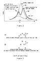
- Figure 2 is a diagram showing an intra-cylinder pressure waveform from a compression stroke to an expansion stroke.
- a line 60 in Figure 2 shows an intra-cylinder pressure waveform at a time of normal combustion.
- a line 62 shows an intra-cylinder pressure waveform at a time of fuel cut.
- a line 64 shows an intra-cylinder pressure waveform in a case of delaying the ignition timing SA during a normal operation involving fuel injection.
- a pre-firing output peak value that is a peak of the output value of the intra-cylinder pressure sensor 16 before firing is obtained at the compression top dead center at which an intra-cylinder volume becomes minimum. Thereafter, with increase in the intra-cylinder volume, the output value decreases, but after firing, an output peak value by combustion of the air-fuel mixture is obtained. Namely, two peaks occur during one cycle.
- an intra-cylinder waveform before firing is the same shape as a motoring waveform without involving combustion.
- a sensitivity fault of the intra-cylinder pressure sensor 16 can be diagnosed during a normal operation. Therefore, many opportunities for fault diagnosis in one trip can be ensured.
- FIG. 3 is a diagram showing a change amount ⁇ P of the intra-cylinder pressures that are detected at predetermined crank angle intervals.
- the change amount ⁇ P at the time of a normal operation shown in (B) of Figure 3 is larger as compared with the change amount ⁇ P at the time of fuel cut shown in (A). Therefore, the S/N ratio is more excellent at the time of a normal operation as compared with that at the time of fuel cut. Therefore, the output value of the intra-cylinder pressure sensor 16 can accurately be detected, with a high S/N ratio.
- the pre-firing output peak value is acquired by delaying the ignition timing so that the firing timing comes after the compression top dead center, within a range in which torque down by delay in the ignition timing is allowed. Subsequently, the pre-firing output peak value, and the peak value of the motoring waveform in the same load condition are compared, whereby a sensitivity fault of the intra-cylinder pressure sensor 16 is diagnosed.
- FIG 4 is a flowchart of a control routine executed by the ECU 50 to provide the aforementioned operation.
- the ECU 50 executes the present routine at predetermined timing during an operation involving fuel injection.
- the ECU 50 detects and stores the output value of the intra-cylinder pressure sensor 16 at every predetermined crank angle (for example, every several degrees).
- the ECU 50 first delays the ignition timing SA so that the firing timing comes after the compression top dead center (step S100). Delay of the ignition timing SA is executed within the range in which torque down is allowed. For example, the ECU 50 increases a delay amount of the ignition timing SA step by step, and delays the ignition timing within the range in which the reduction amount of the engine speed NE does not exceed an allowable value. Note that the delay amount may be set and stored for each operation condition in advance.
- the peak of the intra-cylinder pressure also occurs before firing.
- the ECU 50 acquires the peak of the output value of the intra-cylinder pressure sensor 16 before firing as a pre-firing output peak value P1 (step S 110).
- the ECU 50 acquires a maximum value P2 of the intra-cylinder pressure of the motoring waveform corresponding to a present load factor KL at which the pre-firing output peak value P1 is acquired (step S120). More specifically, the ECU 50 stores in advance a relational table that sets the relation between the load factor KL and the maximum value P2 based on an experiment or the like. The load factor KL is calculated based on the intake air amount GA, the engine speed NE and the like. The ECU 50 acquires the maximum value P2 corresponding to the load factor KL from the relational table.
- step S 130 The detected pre-firing output peak value P1 and the maximum value P2 of the intra-cylinder pressure of the motoring waveform in the same operation condition are compared (step S130).
- the ECU 50 determines whether or not
- step S140 when the condition of step S140 is not established, namely, when
- the sensitivity fault of the intra-cylinder pressure sensor 16 can be diagnosed under all operation conditions, within the range in which torque down is allowed. Further, since the charged air amount is larger at the time of a normal operation as compared with that at the time of fuel cut, the S/N ratio is excellent, and the pre-firing output peak value can accurately be detected. Therefore, according to the system of the present embodiment, the opportunity for fault diagnosis can be ensured in a wide operation region, and accurate fault diagnosis can be carried out with a high S/N ratio. Furthermore, when a fault is present, the intra-cylinder pressure can be corrected properly.
- the engine to which the present invention is applied is not limited to an intra-cylinder direct injection engine as in the aforementioned embodiment.
- the present invention also can be applied to a port-injection type engine.
- the intra-cylinder pressure sensor 16 corresponds to the "intra-cylinder pressure sensor” in the aforesaid first invention
- the ECU 50 corresponds to the "storage means” in the aforesaid third invention, respectively.
- the ECU 50 executes the processing of the above described step S100, whereby the "ignition timing delaying means" in the aforesaid first invention is realized.
- the ECU 50 executes the processing of the above described step S110, whereby the “detection means” in the aforesaid first invention is realized.
- the ECU 50 executes the processing of the above described step S120, whereby the “determination value setting means” in the aforesaid third invention is realized.
- the ECU 50 executes the processing of the above described step S140, whereby the "determination means” in the aforesaid first invention is realized.
- the ECU 50 executes the processing of the above described step S 170, whereby the "correction means” in the aforesaid fourth invention is realized.
- the pre-firing output peak value P1 that is acquired in the above described step S110 corresponds to the "pre-firing output peak value” in the aforesaid first invention
- the maximum value P2 that is acquired in the above described step S120 corresponds to the "determination value” in the aforesaid second invention, respectively.
- FIG. 1 A system of the present embodiment can be realized by causing the ECU 50 to carry out a routine of Figure 6 that will be described later in the configuration shown in Figure 1 .
- the output value of the intra-cylinder pressure sensor 16 is detected in the compression top dead center before firing.
- the pre-firing output peak value described in embodiment 1 is detected in the compression top dead center at a normal time, but this does not apply when a phase shift occurs.
- the ignition timing SA is delayed similarly to embodiment 1, a crank angle at which the pre-firing output peak value is detected is acquired, and based on a difference between the crank angle and the compression top dead center, the phase shift of the intra-cylinder pressure waveform is detected and corrected.
- Figure 5 is a diagram showing an intra-cylinder pressure waveform from the compression stroke to the expansion stroke.
- a line 70 in Figure 5 shows an intra-cylinder pressure waveform in the case of the ignition timing SA being delayed at the time of a normal operation involving combustion. The waveform is the same as that of the line 64 in Figure 2 , and therefore, explanation will be omitted.
- a line 72 shows an intra-cylinder pressure waveform in a case in which a phase shift occurs.
- the S/N ratio is more excellent as compared with that at the time of fuel cut (the line 62 of Figure 2 ), and the pre-firing output peak value can accurately be detected.
- the crank angle at which the pre-firing output peak value is detected also can accurately be detected. Therefore, the phase shift of the intra-cylinder pressure waveform can accurately be calculated from the difference between the aforementioned crank angle and the compression top dead center.
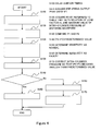
- FIG 6 is a flowchart of a control routine that is executed by the ECU 50 to provide the aforementioned operation.
- the ECU 50 executes the present routine at predetermined timing during an operation involving fuel injection.
- the ECU 50 detects/stores the output value of the intra-cylinder pressure sensor 16 at every predetermined crank angle (for example, every several degrees).
- the ECU 50 first delays the ignition timing SA so that the firing timing comes after the compression top dead center (step S200). Delay of the ignition timing SA is executed within the range in which torque down is allowed. This is similar to step S100 of Figure 4 , and therefore, explanation thereof will be omitted.
- the ECU 50 detects the peak of the output value of the intra-cylinder pressure sensor 16 before firing (pre-firing output peak value). Furthermore, the ECU 50 acquires a crank angle ⁇ 1 at which the pre-firing output peak value is detected (step S210).
- the ECU 50 determines whether or not the crank angle ⁇ 1 corresponds to the compression top dead center (step S220). When the condition of step S220 is established, namely, when the crank angle ⁇ 1 corresponds to the compression top dead center, it is determined that the phase of the intra-cylinder pressure waveform is normal (step S230).
- step S220 determines that a phase shift occurs to the intra-cylinder pressure waveform that is detected by the intra-cylinder pressure sensor 16 (step S240). In this case, the phase of the intra-cylinder pressure waveform is corrected so that the crank angle ⁇ 1 corresponds to the compression top dead center (step S250).
- the phase shift of the intra-cylinder pressure sensor 16 can be diagnosed in all operation conditions, within the range in which torque down is allowed. Since the charged air amount is larger at the time of a normal operation as compared with that at the time of fuel cut, the S/N ratio is excellent, and the pre-firing output peak value and the crank angle thereof can accurately be detected. Therefore, according to the system of the present embodiment, the opportunity for fault diagnosis can be ensured in a wide operation region, and accurate fault diagnosis can be carried out with a high S/N ratio. Further, when a fault is present, the phase shift of the intra-cylinder pressure waveform can be properly corrected.
- Sensitivity correction and phase shift correction of the intra-cylinder pressure sensor 16 may be performed by combining the processing routine ( Figure 6 ) of embodiment 2 with the processing routine ( Figure 4 ) described in embodiment 1.
- the ECU 50 executes the processing of the above described step S220, whereby the "determination means” in the aforesaid fifth invention is realized, and the ECU 50 executes the processing of the above described step S250, whereby the "correction means” in the aforesaid sixth invention is realized, respectively.
- the crank angle ⁇ 1 that is acquired in the above described step S210 corresponds to the "crank angle" in the aforesaid fifth invention.
Landscapes
- Engineering & Computer Science (AREA)
- Chemical & Material Sciences (AREA)
- Combustion & Propulsion (AREA)
- Mechanical Engineering (AREA)
- General Engineering & Computer Science (AREA)
- Analytical Chemistry (AREA)
- Physics & Mathematics (AREA)
- General Physics & Mathematics (AREA)
- Combined Controls Of Internal Combustion Engines (AREA)
- Electrical Control Of Ignition Timing (AREA)
Abstract
Description
- The present invention relates to an intra-cylinder pressure sensor fault diagnostic device that diagnoses whether or not a sensitivity fault occurs to an intra-cylinder pressure sensor that detects an intra-cylinder pressure of an internal combustion engine, and an intra-cylinder pressure sensor sensitivity correction device provided with the same.
- There has been conventionally known an internal combustion engine provided with an intra-cylinder pressure sensor, as disclosed in
Patent Literature 1, for example. Further,Patent Literature 1 discloses detecting a deviation amount of the detected pressure characteristic, which occurs due to hysteresis of the intra-cylinder pressure sensor, with respect to the reference pressure characteristic in the cylinder during fuel cut. More specifically, the deviation amount of the detected pressure characteristic with respect to the reference pressure characteristic is detected by comparing the detected pressures in the symmetrical angle positions in the detected pressure characteristic with the top dead center between the compression stroke and the expansion stroke (hereinafter, called the compression top dead center) as the center. According to the art like this, a sensitivity fault of an intra-cylinder pressure sensor can be diagnosed from the deviation amount that is detected. -
- Patent Literature 1: Japanese Patent Laid-Open No.
2010-127172 - Patent Literature 2: Japanese Patent Laid-Open No.
2009-024553 - Patent Literature 3: Japanese Patent Laid-Open No.
2010-174705 - However, the art of
Patent Literature 1 is limited to the time during fuel cut, and therefore, has the problem of less opportunities for fault diagnosis during one trip. Further, since the intra-cylinder pressure during fuel cut is an extremely low pressure, there is the problem of a low S/N ratio (signal-to-noise ratio) and low detection accuracy of the intra-cylinder pressure. - The present invention is made to solve the problems described above, and has an object to provide an intra-cylinder pressure sensor fault diagnostic device that can ensure an opportunity for fault diagnosis in a wide operation region, and accurately detect an intra-cylinder pressure with a high S/N ratio. Further, the invention has an object to provide an intra-cylinder pressure sensor sensitivity correction device provided with the same.
- A first invention is a fault diagnostic device for intra-cylinder pressure sensor that outputs a value corresponding to an intra-cylinder pressure of an internal combustion engine, the device comprising:
- ignition timing delaying means for delaying ignition timing so that firing timing comes after a compression top dead center to generate peaks of the intra-cylinder pressure before firing and after firing respectively;
- detection means for detecting at least one of an output value of the intra-cylinder pressure sensor in the peak of the intra-cylinder pressure before firing (hereinafter, called a pre-firing output peak value) and a crank angle thereof, when the ignition timing is delayed by the ignition timing delaying means; and
- determination means for determining a fault of the intra-cylinder pressure sensor by using at least one of the pre-firing output peak value and the crank angle thereof.
- A second invention is the intra-cylinder pressure sensor fault diagnostic device according to the first invention,
wherein the detection means detects at least the pre-firing output peak value, and
the determination means determines that a fault is present in the intra-cylinder pressure sensor, when a difference between the pre-firing output peak value and a determination value is at a predetermined value or larger. - A third invention is the intra-cylinder pressure sensor fault diagnostic device according to the second invention, further comprising:
- storage means for storing a relation between a load factor and a maximum intra-cylinder pressure of a motoring waveform in advance; and
- determination value setting means for acquiring the maximum intra-cylinder pressure of the motoring waveform corresponding to a present load factor from the relation, and setting the maximum intra-cylinder pressure as the determination value.
- A fourth invention is an intra-cylinder pressure sensor sensitivity correction device, comprising:
- the intra-cylinder pressure sensor fault diagnostic device according to the second or the third inventions; and
- correction means for correcting an intra-cylinder pressure so that the difference between the pre-firing output peak value and the determination value becomes small, when it is determined that a fault is present in the intra-cylinder pressure sensor.
- A fifth invention is the intra-cylinder pressure sensor fault diagnostic device according to the first invention,
wherein the detection means detects at least a crank angle at which the pre-firing output peak value is detected, and
the determination means determines that a fault is present in the intra-cylinder pressure sensor, when a difference between the crank angle at which the pre-firing output peak value is detected and the compression top dead center is at a predetermined value or larger. - A sixth invention is an intra-cylinder pressure sensor sensitivity correction device, comprising:
- the intra-cylinder pressure sensor fault diagnostic device according to the fifth invention; and
- correction means for correcting a phase of an intra-cylinder pressure waveform so that the difference between the crank angle at which the pre-firing output peak value is detected and the compression top dead center becomes small, when it is determined that a fault is present in the intra-cylinder pressure sensor.
- According to the first to the third inventions, fault diagnosis of the intra-cylinder pressure sensor can be performed based on the pre-firing output peak value that is detected by delaying the ignition timing, during a normal operation involving fuel injection. Since it is during a normal operation, an opportunity for fault diagnosis can be ensured in a wide operation region. Further, since the charged air amount is larger during a normal operation as compared with that during fuel cut, the pre-firing output peak value can accurately be detected with a high S/N ratio. Therefore, fault diagnosis can accurately be performed.
- According to the fourth invention, when it is determined that a fault is present in the intra-cylinder pressure sensor, the intra-cylinder pressure is corrected so that the difference between the pre-firing output peak value and the determination value becomes small, whereby a proper intra-cylinder pressure can be acquired.
- According to the fifth invention, the phase shift of the intra-cylinder pressure waveform can be diagnosed based on the difference between the crank angle of the pre-firing output peak value that is detected during a normal operation involving combustion and the compression top dead center. Since it is during a normal operation, an opportunity for fault diagnosis can be ensured in a wide operation region. Further, since the charged air amount is larger during a normal operation as compared with that during fuel cut, the intra-cylinder pressure can accurately be detected with a high S/N ratio, and therefore, the peak position can accurately be detected. Therefore, fault diagnosis can accurately be performed.
- According to the sixth invention, when it is determined that a fault is present in the intra-cylinder pressure sensor, the phase of the intra-cylinder pressure waveform is corrected so that the difference between the crank angle at which the pre-firing output peak value is detected and the compression top dead center becomes small, whereby a proper intra-cylinder pressure can be acquired.
-
-
Figure 1 is a schematic configuration diagram for explaining a system configuration ofembodiment 1 of the present invention. -
Figure 2 is a diagram showing an intra-cylinder pressure waveform from a compression stroke to an expansion stroke according toembodiment 1 of the present invention. -
Figure 3 is a diagram showing a change amount ΔP of the intra-cylinder pressures that are detected at predetermined crank angle intervals. -
Figure 4 is a flowchart of a control routine executed by theECU 50 to provide the aforementioned operation according toembodiment 1 of the present invention. -
Figure 5 is a diagram showing an intra-cylinder pressure waveform from the compression stroke to the expansion stroke according to embodiment 2 of the present invention. -
Figure 6 is a flowchart of a control routine that is executed by theECU 50 to provide the aforementioned operation according to embodiment 2 of the present invention. - Hereinafter, embodiments of the present invention will be described in detail with reference to the drawings. Note that common elements in the respective drawings are assigned with the same reference signs and redundant explanation will be omitted.
-
Figure 1 is a schematic configuration diagram for explaining a system configuration ofembodiment 1 of the present invention. The system shown inFigure 1 includes an internal combustion engine (hereinafter, simply called an engine) 10 that is a four-stroke engine. Theengine 10 includes a plurality ofcylinders 11, and only onecylinder 11 among them is illustrated inFigure 1 . - To each of the
cylinders 11, an ignition plug 12 that ignites an air-fuel mixture in the cylinder in response to ignition timing SA, a fuel injection valve 14 that directly injects fuel into the cylinder, and an intra-cylinder pressure sensor (CPS) 16 for detecting an intra-cylinder pressure (fuel pressure) P are mounted. Further, to theengine 10, acrank angle sensor 18 for detecting a rotation angle (hereinafter, called a crank angle CA) of a crankshaft, and aknock sensor 19 for detecting knocking are mounted. - An intake system of the
engine 10 is provided with anintake passage 20 that is connected to each of thecylinders 11. Anair cleaner 22 is provided upstream of theintake passage 20. Anair flow meter 24 for detecting a flow rate of air that is taken into the intake passage 20 (hereinafter, called an intake air amount GA) is mounted downstream of theair cleaner 22. An electronically controlledtype throttle valve 26 is provided downstream of theair flow meter 24. Athrottle opening sensor 28 for detecting an opening (hereinafter, called a throttle opening TA) of thethrottle valve 26 is mounted to a vicinity of thethrottle valve 26. Anintake pressure sensor 30 for detecting an intake pressure Pim is mounted downstream of thethrottle valve 26. Anintake valve 32 that opens and closes a space between theintake passage 20 and a combustion chamber of thecylinder 11 is provided at a downstream end of theintake passage 20. - An exhaust system of the
engine 10 is provided with anexhaust passage 34 that is connected to each of the cylinders. Anexhaust valve 35 that opens and closes a space between theexhaust passage 34 and the combustion chamber of thecylinder 11 is provided at an upstream end of theexhaust passage 34. Acatalyst 36 is provided downstream of theexhaust valve 35. For thecatalyst 36, for example, a three-way catalyst is used. Further, theexhaust passage 34 upstream of thecatalyst 36 is provided with anEGR passage 38 that is connected to theintake passage 20. TheEGR passage 38 is provided with anEGR cooler 40. Atemperature sensor 42 is provided in the vicinity of theEGR cooler 40. AnEGR valve 44 is provided downstream of theEGR cooler 40. - A control system of the
engine 10 is provided with an ECU (Electronic Control Unit) 50. Various sensors for detecting an operating state, such as theintra-cylinder pressure sensor 16, thecrank angle sensor 18, theknock sensor 19, theair flow meter 24, thethrottle opening sensor 28, theintake pressure sensor 30, and thetemperature sensor 42 that are described above are connected to an input section of theECU 50. For example, theECU 50 calculates an engine speed NE based on the crank angle CA. TheECU 50 acquires an output value of theintra-cylinder pressure sensor 16 at every predetermined angle (for example, every several degrees). TheECU 50 stores a relation between the output value of theintra-cylinder pressure sensor 16 and the intra-cylinder pressure, which is set by an experiment or the like in advance, and calculates the intra-cylinder pressure corresponding to the output value from the relation. - Further, various actuators for controlling the operating state, such as the ignition plug 12, the fuel injection valve 14, the
throttle valve 26 and theEGR valve 44 that are described above are connected to an output section of theECU 50. TheECU 50 controls the operating state of theengine 10 by operating the various actuators in accordance with a predetermined program based on the outputs of the various sensors described above. For example, theECU 50 can optionally change the ignition timing SA. TheECU 50 can detect torque down from a reduction amount of the engine speed NE by delay of the ignition timing SA. - Next, a method for diagnosing a sensitivity fault of the
intra-cylinder pressure sensor 16 in the aforementioned system will be described.Figure 2 is a diagram showing an intra-cylinder pressure waveform from a compression stroke to an expansion stroke. Aline 60 inFigure 2 shows an intra-cylinder pressure waveform at a time of normal combustion. Aline 62 shows an intra-cylinder pressure waveform at a time of fuel cut. Aline 64 shows an intra-cylinder pressure waveform in a case of delaying the ignition timing SA during a normal operation involving fuel injection. - As shown by the
line 64, when the ignition timing SA is delayed so that firing timing comes after a compression top dead center, a pre-firing output peak value that is a peak of the output value of theintra-cylinder pressure sensor 16 before firing is obtained at the compression top dead center at which an intra-cylinder volume becomes minimum. Thereafter, with increase in the intra-cylinder volume, the output value decreases, but after firing, an output peak value by combustion of the air-fuel mixture is obtained. Namely, two peaks occur during one cycle. When the output value of theintra-cylinder pressure sensor 16 is normal, an intra-cylinder waveform before firing is the same shape as a motoring waveform without involving combustion. By comparing the pre-firing output peak value and the maximum intra-cylinder pressure of the motoring waveform that is stored in advance, a sensitivity fault of theintra-cylinder pressure sensor 16 can be diagnosed during a normal operation. Therefore, many opportunities for fault diagnosis in one trip can be ensured. - Further, since at the time of a normal operation, a charged air amount is larger as compared with that at the time of fuel cut, the intra-cylinder pressure of the motoring waveform portion becomes higher as compared with that at the time of fuel cut.
Figure 3 is a diagram showing a change amount ΔP of the intra-cylinder pressures that are detected at predetermined crank angle intervals. The change amount ΔP at the time of a normal operation shown in (B) ofFigure 3 is larger as compared with the change amount ΔP at the time of fuel cut shown in (A). Therefore, the S/N ratio is more excellent at the time of a normal operation as compared with that at the time of fuel cut. Therefore, the output value of theintra-cylinder pressure sensor 16 can accurately be detected, with a high S/N ratio. - Thus, in the system of the present embodiment, the pre-firing output peak value is acquired by delaying the ignition timing so that the firing timing comes after the compression top dead center, within a range in which torque down by delay in the ignition timing is allowed. Subsequently, the pre-firing output peak value, and the peak value of the motoring waveform in the same load condition are compared, whereby a sensitivity fault of the
intra-cylinder pressure sensor 16 is diagnosed. -
Figure 4 is a flowchart of a control routine executed by theECU 50 to provide the aforementioned operation. TheECU 50 executes the present routine at predetermined timing during an operation involving fuel injection. TheECU 50 detects and stores the output value of theintra-cylinder pressure sensor 16 at every predetermined crank angle (for example, every several degrees). - In the routine shown in
Figure 4 , theECU 50 first delays the ignition timing SA so that the firing timing comes after the compression top dead center (step S100). Delay of the ignition timing SA is executed within the range in which torque down is allowed. For example, theECU 50 increases a delay amount of the ignition timing SA step by step, and delays the ignition timing within the range in which the reduction amount of the engine speed NE does not exceed an allowable value. Note that the delay amount may be set and stored for each operation condition in advance. - By delaying the ignition timing SA as above, the peak of the intra-cylinder pressure also occurs before firing. The
ECU 50 acquires the peak of the output value of theintra-cylinder pressure sensor 16 before firing as a pre-firing output peak value P1 (step S 110). - The
ECU 50 acquires a maximum value P2 of the intra-cylinder pressure of the motoring waveform corresponding to a present load factor KL at which the pre-firing output peak value P1 is acquired (step S120). More specifically, theECU 50 stores in advance a relational table that sets the relation between the load factor KL and the maximum value P2 based on an experiment or the like. The load factor KL is calculated based on the intake air amount GA, the engine speed NE and the like. TheECU 50 acquires the maximum value P2 corresponding to the load factor KL from the relational table. - The detected pre-firing output peak value P1 and the maximum value P2 of the intra-cylinder pressure of the motoring waveform in the same operation condition are compared (step S130). The
ECU 50 determines whether or not |P2-P1| is smaller than a predetermined value (step S 140). When the condition ofstep S 140 is established, namely, when |P2-P1| is smaller than the predetermined value, it is determined that the sensitivity of theintra-cylinder pressure sensor 16 is normal (step S 150). - Meanwhile, when the condition of step S140 is not established, namely, when |P2-P1| is the predetermined value or more, the
ECU 50 determines that a fault occurs to the sensitivity of the intra-cylinder pressure sensor 16 (step S160). In this case, the output value of the intra-cylinder pressure sensor is corrected so that |P2-P1| becomes smaller than the predetermined value (step S 170). For example, with respect to the entire intra-cylinder pressure waveform, correction of multiplying the output value of theintra-cylinder pressure sensor 16 by P2/P1 as a correction coefficient is performed. - As described above, according to the routine shown in
Figure 4 , the sensitivity fault of theintra-cylinder pressure sensor 16 can be diagnosed under all operation conditions, within the range in which torque down is allowed. Further, since the charged air amount is larger at the time of a normal operation as compared with that at the time of fuel cut, the S/N ratio is excellent, and the pre-firing output peak value can accurately be detected. Therefore, according to the system of the present embodiment, the opportunity for fault diagnosis can be ensured in a wide operation region, and accurate fault diagnosis can be carried out with a high S/N ratio. Furthermore, when a fault is present, the intra-cylinder pressure can be corrected properly. - The engine to which the present invention is applied is not limited to an intra-cylinder direct injection engine as in the aforementioned embodiment. The present invention also can be applied to a port-injection type engine.
- Note that in
embodiment 1 described above, theintra-cylinder pressure sensor 16 corresponds to the "intra-cylinder pressure sensor" in the aforesaid first invention, and theECU 50 corresponds to the "storage means" in the aforesaid third invention, respectively. - Further, in this case, the
ECU 50 executes the processing of the above described step S100, whereby the "ignition timing delaying means" in the aforesaid first invention is realized. TheECU 50 executes the processing of the above described step S110, whereby the "detection means" in the aforesaid first invention is realized. TheECU 50 executes the processing of the above described step S120, whereby the "determination value setting means" in the aforesaid third invention is realized. TheECU 50 executes the processing of the above described step S140, whereby the "determination means" in the aforesaid first invention is realized. TheECU 50 executes the processing of the above describedstep S 170, whereby the "correction means" in the aforesaid fourth invention is realized. - Furthermore, in
embodiment 1, the pre-firing output peak value P1 that is acquired in the above described step S110 corresponds to the "pre-firing output peak value" in the aforesaid first invention, and the maximum value P2 that is acquired in the above described step S120 corresponds to the "determination value" in the aforesaid second invention, respectively. - Next, embodiment 2 of the present invention will be described with reference to
Figure 5 to Figure 6 . A system of the present embodiment can be realized by causing theECU 50 to carry out a routine ofFigure 6 that will be described later in the configuration shown inFigure 1 . - In the
aforementioned embodiment 1, in the compression top dead center before firing, the output value of theintra-cylinder pressure sensor 16 is detected. The pre-firing output peak value described inembodiment 1 is detected in the compression top dead center at a normal time, but this does not apply when a phase shift occurs. Thus, in embodiment 2 of the present invention, the ignition timing SA is delayed similarly toembodiment 1, a crank angle at which the pre-firing output peak value is detected is acquired, and based on a difference between the crank angle and the compression top dead center, the phase shift of the intra-cylinder pressure waveform is detected and corrected. -
Figure 5 is a diagram showing an intra-cylinder pressure waveform from the compression stroke to the expansion stroke. Aline 70 inFigure 5 shows an intra-cylinder pressure waveform in the case of the ignition timing SA being delayed at the time of a normal operation involving combustion. The waveform is the same as that of theline 64 inFigure 2 , and therefore, explanation will be omitted. Aline 72 shows an intra-cylinder pressure waveform in a case in which a phase shift occurs. - As described above, at the time of normal operation, the S/N ratio is more excellent as compared with that at the time of fuel cut (the
line 62 ofFigure 2 ), and the pre-firing output peak value can accurately be detected. Similarly, the crank angle at which the pre-firing output peak value is detected also can accurately be detected. Therefore, the phase shift of the intra-cylinder pressure waveform can accurately be calculated from the difference between the aforementioned crank angle and the compression top dead center. -
Figure 6 is a flowchart of a control routine that is executed by theECU 50 to provide the aforementioned operation. TheECU 50 executes the present routine at predetermined timing during an operation involving fuel injection. TheECU 50 detects/stores the output value of theintra-cylinder pressure sensor 16 at every predetermined crank angle (for example, every several degrees). - In the routine shown in
Figure 6 , theECU 50 first delays the ignition timing SA so that the firing timing comes after the compression top dead center (step S200). Delay of the ignition timing SA is executed within the range in which torque down is allowed. This is similar to step S100 ofFigure 4 , and therefore, explanation thereof will be omitted. - By delaying the ignition timing SA as above, a peak of the intra-cylinder pressure also occurs before firing. The intra-cylinder pressure waveform before fifing becomes the same shape as the motoring waveform without involving combustion. The
ECU 50 detects the peak of the output value of theintra-cylinder pressure sensor 16 before firing (pre-firing output peak value). Furthermore, theECU 50 acquires a crank angle θ1 at which the pre-firing output peak value is detected (step S210). - The
ECU 50 determines whether or not the crank angle θ1 corresponds to the compression top dead center (step S220). When the condition of step S220 is established, namely, when the crank angle θ1 corresponds to the compression top dead center, it is determined that the phase of the intra-cylinder pressure waveform is normal (step S230). - Meanwhile, when the condition of step S220 is not established, namely, when the crank angle θ1 shifts from the compression top dead center, the
ECU 50 determines that a phase shift occurs to the intra-cylinder pressure waveform that is detected by the intra-cylinder pressure sensor 16 (step S240). In this case, the phase of the intra-cylinder pressure waveform is corrected so that the crank angle θ1 corresponds to the compression top dead center (step S250). - As described above, according to the routine shown in
Figure 6 , the phase shift of theintra-cylinder pressure sensor 16 can be diagnosed in all operation conditions, within the range in which torque down is allowed. Since the charged air amount is larger at the time of a normal operation as compared with that at the time of fuel cut, the S/N ratio is excellent, and the pre-firing output peak value and the crank angle thereof can accurately be detected. Therefore, according to the system of the present embodiment, the opportunity for fault diagnosis can be ensured in a wide operation region, and accurate fault diagnosis can be carried out with a high S/N ratio. Further, when a fault is present, the phase shift of the intra-cylinder pressure waveform can be properly corrected. - Sensitivity correction and phase shift correction of the
intra-cylinder pressure sensor 16 may be performed by combining the processing routine (Figure 6 ) of embodiment 2 with the processing routine (Figure 4 ) described inembodiment 1. - Note that in embodiment 2 described above, the
ECU 50 executes the processing of the above described step S220, whereby the "determination means" in the aforesaid fifth invention is realized, and theECU 50 executes the processing of the above described step S250, whereby the "correction means" in the aforesaid sixth invention is realized, respectively. Further, in embodiment 2, the crank angle θ1 that is acquired in the above described step S210 corresponds to the "crank angle" in the aforesaid fifth invention. -
- 10
- engine
- 11
- cylinder
- 12
- ignition plug
- 14
- fuel injection valve
- 16
- intra-cylinder pressure sensor
- 18
- crank angle sensor
- 19
- knock sensor
- 20
- intake passage
- 22
- air cleaner
- 24
- air flow meter
- 26
- throttle valve
- 28
- throttle opening sensor
- 30
- intake pressure sensor
- 36
- catalyst
Claims (6)
- A fault diagnostic device for intra-cylinder pressure sensor that outputs a value corresponding to an intra-cylinder pressure of an internal combustion engine, the device comprising:ignition timing delaying means for delaying ignition timing so that firing timing comes after a compression top dead center to generate peaks of the intra-cylinder pressure before firing and after firing respectively;detection means for detecting at least one of an output value of the intra-cylinder pressure sensor in the peak of the intra-cylinder pressure before firing (hereinafter, called a pre-firing output peak value) and a crank angle thereof, when the ignition timing is delayed by the ignition timing delaying means; anddetermination means for determining a fault of the intra-cylinder pressure sensor by using at least one of the pre-firing output peak value and the crank angle thereof.
- The intra-cylinder pressure sensor fault diagnostic device according to claim 1,
wherein the detection means detects at least the pre-firing output peak value, and
the determination means determines that a fault is present in the intra-cylinder pressure sensor, when a difference between the pre-firing output peak value and a determination value is at a predetermined value or larger. - The intra-cylinder pressure sensor fault diagnostic device according to claim 2, further comprising:storage means for storing a relation between a load factor and a maximum intra-cylinder pressure of a motoring waveform in advance; anddetermination value setting means for acquiring the maximum intra-cylinder pressure of the motoring waveform corresponding to a present load factor from the relation, and setting the maximum intra-cylinder pressure as the determination value.
- An intra-cylinder pressure sensor sensitivity correction device, comprising:the intra-cylinder pressure sensor fault diagnostic device according to claim 2 or 3; andcorrection means for correcting an intra-cylinder pressure so that the difference between the pre-firing output peak value and the determination value becomes small, when it is determined that a fault is present in the intra-cylinder pressure sensor.
- The intra-cylinder pressure sensor fault diagnostic device according to claim 1,
wherein the detection means detects at least a crank angle at which the pre-firing output peak value is detected, and
the determination means determines that a fault is present in the intra-cylinder pressure sensor, when a difference between the crank angle at which the pre-firing output peak value is detected and the compression top dead center is at a predetermined value or larger. - An intra-cylinder pressure sensor sensitivity correction device, comprising:the intra-cylinder pressure sensor fault diagnostic device according to claim 5; andcorrection means for correcting a phase of an intra-cylinder pressure waveform so that the difference between the crank angle at which the pre-firing output peak value is detected and the compression top dead center becomes small, when it is determined that a fault is present in the intra-cylinder pressure sensor.
Applications Claiming Priority (1)
| Application Number | Priority Date | Filing Date | Title |
|---|---|---|---|
| PCT/JP2011/076087 WO2013069157A1 (en) | 2011-11-11 | 2011-11-11 | Intra-cylinder pressure sensor fault diagnostic device and intra-cylinder sensor sensitivity correction device provided with same |
Publications (2)
| Publication Number | Publication Date |
|---|---|
| EP2778379A1 true EP2778379A1 (en) | 2014-09-17 |
| EP2778379A4 EP2778379A4 (en) | 2015-08-05 |
Family
ID=48288814
Family Applications (1)
| Application Number | Title | Priority Date | Filing Date |
|---|---|---|---|
| EP11875589.1A Withdrawn EP2778379A4 (en) | 2011-11-11 | 2011-11-11 | PRESSURE SENSOR DIAGNOSTIC DEVICE MOUNTED IN THE CYLINDER, AND SENSOR SENSITIVITY CORRECTION DEVICE MOUNTED IN THE CYLINDER, EQUIPPED WITH SAME |
Country Status (4)
| Country | Link |
|---|---|
| US (1) | US9435707B2 (en) |
| EP (1) | EP2778379A4 (en) |
| JP (1) | JP6006228B2 (en) |
| WO (1) | WO2013069157A1 (en) |
Cited By (3)
| Publication number | Priority date | Publication date | Assignee | Title |
|---|---|---|---|---|
| DE102015205917A1 (en) * | 2014-04-02 | 2015-10-08 | Honda Motor Co., Ltd. | Cylinder internal pressure detecting device for an internal combustion engine |
| DE102015223202A1 (en) * | 2014-11-25 | 2016-05-25 | Honda Motor Co., Ltd. | COMBUSTION PARAMETER CALCULATION DEVICE FOR INTERNAL COMBUSTION ENGINE |
| WO2021098937A1 (en) * | 2019-11-18 | 2021-05-27 | Wärtsilä Finland Oy | A method of detecting a deviation in operation of a pressure sensor for internal combustion piston engine and computer readable memory device for detecting a deviation in operation of a pressure sensor |
Families Citing this family (4)
| Publication number | Priority date | Publication date | Assignee | Title |
|---|---|---|---|---|
| WO2017073340A1 (en) * | 2015-10-27 | 2017-05-04 | 日立オートモティブシステムズ株式会社 | Control device for internal combustion engine |
| JP2017227198A (en) * | 2016-06-24 | 2017-12-28 | トヨタ自動車株式会社 | Diesel engine control device |
| JP6988746B2 (en) * | 2018-09-03 | 2022-01-05 | マツダ株式会社 | Failure diagnosis device for in-cylinder pressure sensor |
| JP2020101127A (en) * | 2018-12-21 | 2020-07-02 | マツダ株式会社 | Abnormality diagnosis device of in-cylinder pressure sensor |
Family Cites Families (15)
| Publication number | Priority date | Publication date | Assignee | Title |
|---|---|---|---|---|
| JPS59206648A (en) * | 1983-01-26 | 1984-11-22 | Nissan Motor Co Ltd | Calibration of sensor for detecting combustion chamber inner pressure for internal-combustion engine |
| JPS62192627A (en) * | 1986-02-19 | 1987-08-24 | Honda Motor Co Ltd | How to correct the cylinder pressure of an internal combustion engine |
| KR940002066B1 (en) * | 1990-08-24 | 1994-03-16 | 미쯔비시 덴끼 가부시기가이샤 | Failure, detecting method for pressure sensor |
| JP2893233B2 (en) * | 1993-12-09 | 1999-05-17 | 株式会社ユニシアジェックス | Diagnostic device for in-cylinder pressure sensor |
| JPH09195844A (en) * | 1996-01-11 | 1997-07-29 | Unisia Jecs Corp | In-cylinder pressure detection device for internal combustion engine |
| SE521998C2 (en) * | 2001-06-13 | 2004-01-07 | Abb Ab | Method for determining the top dead center of an internal combustion engine |
| JP4716283B2 (en) | 2006-02-08 | 2011-07-06 | 本田技研工業株式会社 | Air-fuel ratio control device for internal combustion engine |
| FR2897900B1 (en) * | 2006-02-28 | 2008-06-06 | Inst Francais Du Petrole | METHOD FOR CONTROLLING THE COMBUSTION PHASE OF AN INTERNAL COMBUSTION ENGINE, ESPECIALLY DIRECT INJECTION ENGINE OF PETROL TYPE |
| JP2009024553A (en) | 2007-07-18 | 2009-02-05 | Toyota Motor Corp | Internal combustion engine control system |
| US7779679B2 (en) * | 2008-04-14 | 2010-08-24 | Gm Global Technology Operations, Inc. | Fuel system diagnostics by analyzing cylinder pressure signal |
| JP2010127172A (en) | 2008-11-27 | 2010-06-10 | Denso Corp | Cylinder internal pressure sensor characteristics detection device |
| JP2010174705A (en) | 2009-01-28 | 2010-08-12 | Toyota Motor Corp | Control device for internal combustion engine |
| US8301362B2 (en) * | 2009-03-27 | 2012-10-30 | GM Global Technology Operations LLC | Method and system for generating a diagnostic signal of an engine component using an in-cylinder pressure sensor |
| EP2375038B1 (en) | 2010-04-08 | 2015-03-04 | Delphi International Operations Luxembourg S.à r.l. | Diagnosis device and method using an in-cylinder pressure sensor in an internal combustion engine |
| US8600644B2 (en) * | 2011-05-23 | 2013-12-03 | GM Global Technology Operations LLC | Cylinder pressure sensor compensation systems and methods |
-
2011
- 2011-11-11 EP EP11875589.1A patent/EP2778379A4/en not_active Withdrawn
- 2011-11-11 WO PCT/JP2011/076087 patent/WO2013069157A1/en not_active Ceased
- 2011-11-11 US US14/350,626 patent/US9435707B2/en not_active Expired - Fee Related
- 2011-11-11 JP JP2013542791A patent/JP6006228B2/en not_active Expired - Fee Related
Cited By (7)
| Publication number | Priority date | Publication date | Assignee | Title |
|---|---|---|---|---|
| DE102015205917A1 (en) * | 2014-04-02 | 2015-10-08 | Honda Motor Co., Ltd. | Cylinder internal pressure detecting device for an internal combustion engine |
| US9702787B2 (en) | 2014-04-02 | 2017-07-11 | Honda Motor Co., Ltd. | In-cylinder pressure detecting apparatus for internal combustion engine |
| DE102015205917B4 (en) * | 2014-04-02 | 2018-02-08 | Honda Motor Co., Ltd. | Cylinder internal pressure detecting device for an internal combustion engine |
| DE102015223202A1 (en) * | 2014-11-25 | 2016-05-25 | Honda Motor Co., Ltd. | COMBUSTION PARAMETER CALCULATION DEVICE FOR INTERNAL COMBUSTION ENGINE |
| DE102015223202B4 (en) * | 2014-11-25 | 2017-11-23 | Honda Motor Co., Ltd. | COMBUSTION PARAMETER CALCULATION DEVICE FOR INTERNAL COMBUSTION ENGINE |
| US10416041B2 (en) | 2014-11-25 | 2019-09-17 | Honda Motor Co., Ltd. | Combustion state parameter calculation method for internal combustion engine |
| WO2021098937A1 (en) * | 2019-11-18 | 2021-05-27 | Wärtsilä Finland Oy | A method of detecting a deviation in operation of a pressure sensor for internal combustion piston engine and computer readable memory device for detecting a deviation in operation of a pressure sensor |
Also Published As
| Publication number | Publication date |
|---|---|
| EP2778379A4 (en) | 2015-08-05 |
| US20140260574A1 (en) | 2014-09-18 |
| JPWO2013069157A1 (en) | 2015-04-02 |
| WO2013069157A1 (en) | 2013-05-16 |
| US9435707B2 (en) | 2016-09-06 |
| JP6006228B2 (en) | 2016-10-12 |
Similar Documents
| Publication | Publication Date | Title |
|---|---|---|
| US9435707B2 (en) | Intra-cylinder pressure sensor fault diagnostic device and intra-cylinder sensor sensitivity correction device provided with same | |
| JP5293890B2 (en) | Control device for internal combustion engine | |
| JP5397570B2 (en) | Control device for internal combustion engine | |
| EP2910760A1 (en) | In-cylinder pressure detection device for internal combustion engine | |
| US20180066593A1 (en) | Control Device for Internal Combustion Engine and Abnormal Combustion Detecting Method | |
| US8744733B2 (en) | Control apparatus for internal combustion engine | |
| JP6270210B2 (en) | In-cylinder pressure sensor diagnostic method and vehicle operation control device | |
| US20150219026A1 (en) | In-cylinder pressure detection device for internal combustion engine | |
| CN113323758A (en) | Control system and control method for preventing engine from pre-ignition | |
| JP2010127102A (en) | Abnormality determining device of cylinder internal pressure sensor | |
| JP5737196B2 (en) | Control device for internal combustion engine | |
| JP2012207656A (en) | Control device of internal combustion engine | |
| JP2007231883A (en) | Air-fuel ratio control device for internal combustion engine | |
| JP5614377B2 (en) | Control device for internal combustion engine | |
| EP2549083A1 (en) | Control device for internal combustion engine | |
| JP5737205B2 (en) | In-cylinder pressure sensor abnormality diagnosis device | |
| US12163858B2 (en) | Misfire determination device for internal combustion engine | |
| JP5488286B2 (en) | Combustion state detection system for internal combustion engine | |
| JP5240208B2 (en) | Control device for internal combustion engine | |
| JP2016156295A (en) | Fuel injection control device and fuel injection control method for internal combustion engine | |
| JP2012112314A (en) | Internal combustion engine control device |
Legal Events
| Date | Code | Title | Description |
|---|---|---|---|
| PUAI | Public reference made under article 153(3) epc to a published international application that has entered the european phase |
Free format text: ORIGINAL CODE: 0009012 |
|
| 17P | Request for examination filed |
Effective date: 20140408 |
|
| AK | Designated contracting states |
Kind code of ref document: A1 Designated state(s): AL AT BE BG CH CY CZ DE DK EE ES FI FR GB GR HR HU IE IS IT LI LT LU LV MC MK MT NL NO PL PT RO RS SE SI SK SM TR |
|
| DAX | Request for extension of the european patent (deleted) | ||
| RA4 | Supplementary search report drawn up and despatched (corrected) |
Effective date: 20150706 |
|
| RIC1 | Information provided on ipc code assigned before grant |
Ipc: F02D 41/22 20060101ALI20150630BHEP Ipc: F02D 45/00 20060101AFI20150630BHEP Ipc: F02D 41/00 20060101ALI20150630BHEP Ipc: F02D 35/02 20060101ALI20150630BHEP |
|
| STAA | Information on the status of an ep patent application or granted ep patent |
Free format text: STATUS: EXAMINATION IS IN PROGRESS |
|
| 17Q | First examination report despatched |
Effective date: 20200728 |
|
| STAA | Information on the status of an ep patent application or granted ep patent |
Free format text: STATUS: THE APPLICATION IS DEEMED TO BE WITHDRAWN |
|
| 18D | Application deemed to be withdrawn |
Effective date: 20230217 |