EP2778376A2 - System and method for engine transient power response - Google Patents
System and method for engine transient power response Download PDFInfo
- Publication number
- EP2778376A2 EP2778376A2 EP14159110.7A EP14159110A EP2778376A2 EP 2778376 A2 EP2778376 A2 EP 2778376A2 EP 14159110 A EP14159110 A EP 14159110A EP 2778376 A2 EP2778376 A2 EP 2778376A2
- Authority
- EP
- European Patent Office
- Prior art keywords
- engine
- control signal
- request
- power level
- position control
- Prior art date
- Legal status (The legal status is an assumption and is not a legal conclusion. Google has not performed a legal analysis and makes no representation as to the accuracy of the status listed.)
- Granted
Links
- 238000000034 method Methods 0.000 title claims abstract description 35
- 230000004044 response Effects 0.000 title claims abstract description 21
- 230000001052 transient effect Effects 0.000 title claims description 25
- 230000001133 acceleration Effects 0.000 claims abstract description 77
- 230000007246 mechanism Effects 0.000 claims abstract description 27
- 238000005259 measurement Methods 0.000 claims description 11
- 238000012545 processing Methods 0.000 claims description 10
- 230000006735 deficit Effects 0.000 claims description 5
- 239000007789 gas Substances 0.000 description 20
- 230000006870 function Effects 0.000 description 10
- 239000003570 air Substances 0.000 description 5
- 239000000446 fuel Substances 0.000 description 4
- 230000007704 transition Effects 0.000 description 4
- 230000008859 change Effects 0.000 description 3
- 239000000567 combustion gas Substances 0.000 description 3
- 238000010586 diagram Methods 0.000 description 3
- 238000004891 communication Methods 0.000 description 2
- 230000007423 decrease Effects 0.000 description 2
- 238000012986 modification Methods 0.000 description 2
- 230000004048 modification Effects 0.000 description 2
- 239000012080 ambient air Substances 0.000 description 1
- 230000000052 comparative effect Effects 0.000 description 1
- 230000003247 decreasing effect Effects 0.000 description 1
- 230000008569 process Effects 0.000 description 1
- 230000009467 reduction Effects 0.000 description 1
- 238000012552 review Methods 0.000 description 1
- 238000004088 simulation Methods 0.000 description 1
Images


Classifications
-
- F—MECHANICAL ENGINEERING; LIGHTING; HEATING; WEAPONS; BLASTING
- F02—COMBUSTION ENGINES; HOT-GAS OR COMBUSTION-PRODUCT ENGINE PLANTS
- F02D—CONTROLLING COMBUSTION ENGINES
- F02D29/00—Controlling engines, such controlling being peculiar to the devices driven thereby, the devices being other than parts or accessories essential to engine operation, e.g. controlling of engines by signals external thereto
- F02D29/02—Controlling engines, such controlling being peculiar to the devices driven thereby, the devices being other than parts or accessories essential to engine operation, e.g. controlling of engines by signals external thereto peculiar to engines driving vehicles; peculiar to engines driving variable pitch propellers
-
- F—MECHANICAL ENGINEERING; LIGHTING; HEATING; WEAPONS; BLASTING
- F02—COMBUSTION ENGINES; HOT-GAS OR COMBUSTION-PRODUCT ENGINE PLANTS
- F02C—GAS-TURBINE PLANTS; AIR INTAKES FOR JET-PROPULSION PLANTS; CONTROLLING FUEL SUPPLY IN AIR-BREATHING JET-PROPULSION PLANTS
- F02C9/00—Controlling gas-turbine plants; Controlling fuel supply in air- breathing jet-propulsion plants
- F02C9/48—Control of fuel supply conjointly with another control of the plant
- F02C9/50—Control of fuel supply conjointly with another control of the plant with control of working fluid flow
- F02C9/54—Control of fuel supply conjointly with another control of the plant with control of working fluid flow by throttling the working fluid, by adjusting vanes
-
- F—MECHANICAL ENGINEERING; LIGHTING; HEATING; WEAPONS; BLASTING
- F05—INDEXING SCHEMES RELATING TO ENGINES OR PUMPS IN VARIOUS SUBCLASSES OF CLASSES F01-F04
- F05D—INDEXING SCHEME FOR ASPECTS RELATING TO NON-POSITIVE-DISPLACEMENT MACHINES OR ENGINES, GAS-TURBINES OR JET-PROPULSION PLANTS
- F05D2270/00—Control
- F05D2270/01—Purpose of the control system
- F05D2270/04—Purpose of the control system to control acceleration (u)
- F05D2270/044—Purpose of the control system to control acceleration (u) by making it as high as possible
-
- F—MECHANICAL ENGINEERING; LIGHTING; HEATING; WEAPONS; BLASTING
- F05—INDEXING SCHEMES RELATING TO ENGINES OR PUMPS IN VARIOUS SUBCLASSES OF CLASSES F01-F04
- F05D—INDEXING SCHEME FOR ASPECTS RELATING TO NON-POSITIVE-DISPLACEMENT MACHINES OR ENGINES, GAS-TURBINES OR JET-PROPULSION PLANTS
- F05D2270/00—Control
- F05D2270/01—Purpose of the control system
- F05D2270/05—Purpose of the control system to affect the output of the engine
- F05D2270/053—Explicitly mentioned power
-
- F—MECHANICAL ENGINEERING; LIGHTING; HEATING; WEAPONS; BLASTING
- F05—INDEXING SCHEMES RELATING TO ENGINES OR PUMPS IN VARIOUS SUBCLASSES OF CLASSES F01-F04
- F05D—INDEXING SCHEME FOR ASPECTS RELATING TO NON-POSITIVE-DISPLACEMENT MACHINES OR ENGINES, GAS-TURBINES OR JET-PROPULSION PLANTS
- F05D2270/00—Control
- F05D2270/30—Control parameters, e.g. input parameters
- F05D2270/304—Spool rotational speed
-
- F—MECHANICAL ENGINEERING; LIGHTING; HEATING; WEAPONS; BLASTING
- F05—INDEXING SCHEMES RELATING TO ENGINES OR PUMPS IN VARIOUS SUBCLASSES OF CLASSES F01-F04
- F05D—INDEXING SCHEME FOR ASPECTS RELATING TO NON-POSITIVE-DISPLACEMENT MACHINES OR ENGINES, GAS-TURBINES OR JET-PROPULSION PLANTS
- F05D2270/00—Control
- F05D2270/30—Control parameters, e.g. input parameters
- F05D2270/335—Output power or torque
Definitions
- the application relates generally to the control of gas turbine engines, and more particularly to controlling transient aspects thereof.
- inlet mass flow can be increased by accelerating the gas generator of the engine, thereby increasing the engine's power.
- a bleed valve may be actuated either actively or passively.
- active actuation of the bleed valve adds weight to the engine while passive actuation increases the gas path temperature and decreases the gas generator speed of the engine.
- the running line of the engine can alternatively be lowered to improve transient engine performance. This may however result in a decrease in the overall efficiency, an increase in specific fuel consumption, and maximum required operating gas generator speed of the engine while increasing the overall operating temperature thereof.
- casing treatment may also be used, this technique may lower the efficiency of the engine.
- a system for controlling an engine comprising a receiving unit adapted to receive a request signal indicative of a demand for the engine to output a required power level; and a processing unit adapted to generate in response to the request signal a position control signal indicative of a first request for adjusting a present position of a variable geometry mechanism of the engine towards a commanded position to achieve the required power level, generate on the basis of the position control signal an acceleration rate control signal indicative of a second request for adjusting an acceleration rate of the engine in accordance with the commanded position of the variable geometry mechanism, and output the position control signal and the acceleration rate control signal to the engine.
- a method for controlling an engine comprising receiving a request signal indicative of a demand for the engine to output a required power level; generating in response to the request signal a position control signal indicative of a first request for adjusting a present position of a variable geometry mechanism of the engine towards a commanded position to achieve the required power level; generating on the basis of the position control signal an acceleration rate control signal indicative of a second request for adjusting an acceleration rate of the engine in accordance with the commanded position of the variable geometry mechanism; and outputting the position control signal and the acceleration rate control signal to the engine.
- a system for controlling an engine comprising means for receiving a request signal indicative of a demand for the engine to output a required power level; means for generating in response to the request signal a position control signal indicative of a first request for adjusting a present position of a variable geometry mechanism of the engine towards a commanded position to achieve the required power level; means for generating on the basis of the position control signal an acceleration rate control signal indicative of a second request for adjusting an acceleration rate of the engine in accordance with the commanded position of the variable geometry mechanism; and means for outputting the position control signal and the acceleration rate control signal to the engine.
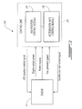
- Fig.1 illustrates a gas turbine engine 10 of a type preferably provided for use in subsonic flight, generally comprising in serial flow communication, a compressor section 12 for pressurizing the air, a combustor 14 in which the compressed air is mixed with fuel and ignited for generating an annular stream of hot combustion gases, and a turbine section 16 for extracting energy from the combustion gases.
- the combustion gases flowing out of the combustor 14 circulate through the turbine section 16 and are expelled through an exhaust duct 18.
- the turbine section 16 includes a compressor turbine 20 in driving engagement with the compressor section 12 through a high pressure shaft 22, and a power turbine 24 in driving engagement with a power shaft 26.
- the power shaft 26 is in driving engagement with an output shaft 28 through a reduction gearbox (not shown).
- gas turbine engine 10 may alternatively be another type of engine, for example a turbofan engine, also generally comprising in serial flow communication a compressor section, a combustor, and a turbine section, and a fan through which ambient air is propelled.
- a turboprop engine may also apply.
- the engine 10 is described herein for flight applications, it should be understood that other uses, such as industrial or the like, may apply.
- variable geometry mechanism illustratively consists of variable guide vanes (VGVs), which may be one of inlet compressor guide vanes for directing air into the compressor section 12, outlet guide vanes for directing air out of the compressor section 12, variable stator vanes for directing incoming air into rotor blades (not shown) of the engine 10, variable nozzles, and the like.
- VGVs variable guide vanes
- the system 100 may be used to adjust one or more of the above-mentioned VGVs for the purpose of decreasing the response time of the engine 10 during rapid engine transitions, e.g. from low to high power levels. Indeed, adjustment of the position (e.g. the angle) of the VGVs can impact the inlet mass flow to the engine 10, and in turn allow the engine 10 to operate at a required power.
- the system 100 illustratively comprises a control unit 102, which is coupled to the engine 10 and illustratively includes a VGV position control module 104 and an acceleration rate control module 106.
- the control unit 102 may comprise a digital computer or Engine Control Unit (ECU) (not shown) using a Central Processing Unit (CPU) (not shown).
- ECU Engine Control Unit
- CPU Central Processing Unit
- the VGV position control module 104 illustratively outputs a VGV position control signal to enable dynamic auto-scheduling of the VGVs.
- the position of the VGVs can be dynamically varied between a steady state schedule and a transient schedule.
- the steady state schedule provides optimum response and performance of the engine 10 when the latter operates at a low power level.
- the VGV position control module 104 adjusts the position of the VGVs so that the gas generator (or rotor) speed (NG) of the engine 10 is maximized.
- the inlet mass flow of the engine 10 and the efficiency of the compressor section 12 can be minimized. As a result, the gas generator speed of the engine 10 is increased.
- the transient schedule provides optimum engine response and performance when the engine 10 operates at a high power level.
- the VGV position control module 104 predictively optimizes the engine's output power.
- the VGVs may be moved to more open settings until they reach a position that optimizes fuel consumption by the engine 10. Higher power levels can therefore be achieved.
- the VGV position control module 104 dynamically adjusts the position of the VGVs from the steady state schedule towards the transient schedule proportionally to the required engine power. For instance, the more the system 100 senses a deficit in power (whether actual or upcoming), the more the VGV position control module 104 adjusts the position of the VGVs towards the transient schedule.
- the VGV position control module 104 may thus constantly modulate the position of the VGVs between the steady state and transient schedules in accordance with the difference between the actual power presently output by the engine 10 and the required power.
- the acceleration rate control module 106 illustratively outputs an acceleration rate control signal to modulate the maximum allowed acceleration reference of the engine 10 according to the VGV position.
- the acceleration capability of the engine 10 can be dynamically modified in accordance with the position of the VGVs, as adjusted in response to the VGV position control signal from the VGV position control module 104.
- the achievable change in the engine's acceleration rate may depend on the surge margin of the engine 10.
- the acceleration rate control module 106 increases the engine's acceleration rate as the position of the VGVs is adjusted towards more open settings in the transient schedule. In particular, the more the VGVs are opened as commanded by the VGV position control signal, the more the maximum allowed acceleration reference of the engine 10 is increased as commanded by the acceleration rate control signal, thereby allowing greater engine acceleration.
- the VGV position control module 104 illustratively comprises a required VGV request bias computation module 202, a minimum VGV bias computation module 204, a maximum VGV bias computation module 206, a steady state VGV request computation module 208, a range limit module 210, and a VGV control loop 212.
- the control unit 102 illustratively receives at a receiving unit thereof (not shown) a measurement of the shaft horse power (SHP), i.e. the output power, of the engine 10 as well as a request for a required shaft horse power (SHPrequest).
- SHP shaft horse power
- SHPrequest required shaft horse power
- the required shaft horse power may be calculated by the engine's power governor (not shown).
- the engine's power is described herein as being measured using shaft horse power, it should be understood that other engine parameters may be used. For instance, the engine's spool speed (e.g. from the power turbine 24, compressor turbine 20, or the like), the engine's fuel flow, or the engine's thrust may apply.
- the request may indicate that a power level higher than the actual power level output by the engine 10 is needed. It should however be understood that the request may also indicate that a lower power level is needed.
- the measurement of the engine's output power and the power request are then sent to the required VGV request bias computation module 202, which computes therefrom the adjustment or bias in VGV position that is to be requested to achieve the required power.
- the VGV request bias computation module 202 first computes at a difference operator 214 the difference (SHPerror) between the engine's output power level and the required power level indicated in the power request.
- the error is then multiplied by a proportional gain (Kp) at a multiplier 216 in order for the position of the VGV to ultimately be adjusted proportionally to the power requirement.
- the gain is computed by a gain controller 218, which may use a predetermined map, curve, table, or the like (not shown) retrieved from memory (not shown). It should be understood that although a map is described herein for illustrative purposes, algorithms or other logic, such as polynomial equations or full proportional-integral-derivative (PID) controllers, may also be used.
- the map may represent the gain (Kp) as a function of the difference between the engine's output power and the required power.
- the map may be established for a reference pressure (Pref) and temperature (Tref) at the inlet of the engine 10. It should be understood that the pressure and temperature reference may be obtained anywhere in the engien's compressor section 12, from the inlet to the diffuser (not shown).
- the gain controller 218 retrieves from the map the corresponding value of the gain.
- the multiplier 216 then outputs a signal comprising the required VGV request bias and this bias is sent to the range limit module 210.
- the range limit module 210 further receives a minimum VGV bias value from the minimum VGV bias computation module 204 and a maximum VGV bias value from the maximum VGV bias computation module 206.
- the minimum VGV bias is illustratively representative of the minimum allowable value for the adjustment or bias in the VGVs' position while the maximum VGV bias is representative of the maximum allowable value for the VGVs' position bias.
- NGN corrected gas generator speed
- the NGN value is then used by the minimum VGV bias computation module 204 and the maximum VGV bias computation module 206 to respectively output the minimum value of the VGV bias and the maximum value of the VGV bias.
- each one of the modules 204, 206, and 208 determines its output from a map retrieved from the memory.
- the minimum VGV bias computation module 204 may use a map of the minimum VGV bias as a function of the corrected gas generator speed (NGN) at the reference pressure and temperature.
- NGN corrected gas generator speed
- the minimum VGV bias computation module 204 may then retrieve from the map the corresponding minimum VGV bias value.
- the maximum VGV bias computation module 206 may use a map of the maximum VGV bias as a function of the corrected gas generator speed (NGN) at the reference pressure and temperature. Upon receiving the NGN value, the maximum VGV bias computation module 206 may then retrieve from the map the corresponding maximum VGV bias value.
- NGN corrected gas generator speed
- the range limit module 210 may then process the received required VGV request bias, minimum VGV bias, and maximum VGV bias to output the VGV bias request.
- the VGV bias request is indicative of the bias in VGV position that is requested to achieve the required power.
- the value of the VGV bias request is comprised within the specified minimum and maximum VGV bias limits.
- the range limit module 210 bounds the output it generates within known or specified minimum and maximum values.
- the range limit module 210 bounds the VGV bias request between the minimum VGV bias output by the minimum VGV bias computation module 204 and the maximum VGV bias value output by the maximum VGV bias computation module 206.
- the range limit module 210 bounds the VGV bias request between 0 and 20.
- the range limit module 210 may limit the VGV bias request from -100% to 100% of the full range of the VGVs' actuator system.
- the VGV bias request is further summed at a summing junction 220 with a steady state VGV request received from the steady state VGV request computation module 208.
- the steady state VGV request is illustratively representative of the VGV position to be achieved in the steady state schedule.
- the steady state VGV request may be obtained by the steady state VGV request computation module 208 using a map of the steady state VGV request as a function of the NGN value at the reference pressure and temperature.
- the summing junction 220 then outputs an optimized VGV request, which is indicative of the request to transition, proportionally to the power request, the position of the VGVs from the optimum steady state position, as indicated in the steady state VGV request, towards the optimum transient position.
- the optimized VGV request is then sent to the VGV control loop 212, which accordingly outputs the VGV position control signal.
- the VGV control signal is indicative of the VGV position commanded from the control unit 102 and is sent to the engine 10 for adjusting the position of the VGVs accordingly.
- the VGV control signal is also fed back to the VGV control loop 212 for closed loop control of the position of the VGVs.
- both the optimized VGV request and the VGV position control signal are also sent to the acceleration rate control module 106 to enable the latter to compute the desired acceleration adjustment corresponding to the adjustment in VGV position.
- the VGV position control module 104 if the change in the engine's output power is no longer required, e.g. a corresponding maneuver having generated the power request is aborted, the VGV position control module 104 generates the VGV position control signal to command the VGVs to automatically return towards the steady state schedule. As such, the change in engine output power is promptly limited.
- the acceleration rate control module 106 illustratively comprises an acceleration bias computation module 302, a nominal acceleration limit computation module 304, and an acceleration control loop 306.
- the optimized VGV request and the VGV position control signal are received from the VGV position control module 104 at the acceleration bias computation module 302.
- the difference between the optimized VGV request and the VGV position control signal is then computed at a difference operator 308 to output the actual transient VGV bias.
- the actual transient VGV bias is then compared to an acceleration limit bias to generate the acceleration bias, which is representative of the adjustment in the engine's acceleration rate desired to comply with the adjustment in the VGVs' position.
- the acceleration limit bias i.e.
- the maximum allowable acceleration limit may be obtained using a characterizing block 310.
- the NGN value may be input into the characterizing block 310, which uses a map of the acceleration limit bias as a function of the corrected gas generator speed (NGN) at the reference pressure and temperature. Comparison with the acceleration limit bias determined by the characterizing block 310 may be used to ensure that the acceleration bias output by the acceleration bias computation module 302 remains within acceptable limits.
- the acceleration bias is then added at a summing junction 312 to a nominal acceleration limit in order to output an optimized acceleration limit, which is representative of a request to transition from the nominal engine acceleration rate to the acceleration rate that is optimum given the commanded VGV position adjustment.
- the nominal acceleration limit is illustratively generated by the nominal acceleration limit computation module 304 using a map of the nominal acceleration limit as a function of the NGN value at the reference pressure and temperature.
- the optimized acceleration limit is then sent to the acceleration control loop 306, which generates therefrom the acceleration rate control signal. This signal is then sent to the engine 10 to modify the acceleration limit thereof and enable engine operation at the modified acceleration rate.
- the acceleration rate control signal is further fed back to the acceleration control loop for closed loop control of the engine's acceleration rate.
- the method 400 illustratively comprises receiving at step 402 a measurement indicative of the speed of the engine, i.e. the gas generator speed, receiving at step 404 a measurement of the output power of the engine, and receiving at step 406 a power request. It should be understood that the order of steps 402, 404, and 406 may be altered. The next step 408 may then be to compute a difference between the output power and the power request.
- a first control signal for causing adjustment of the position of the VGVs may then be generated at step 410 on the basis of the difference computed at step 408 as well as on the basis of the measurement indicative of the engine speed, as received at step 402.
- a second control signal for causing adjustment of the engine's acceleration rate may further be generated at step 412.
- the acceleration control signal may be computed on the basis of the VGV position control signal computed at step 410 and of the measurement indicative of the engine speed, as received at step 402.
- the method 400 may then output at step 414 the generated control signals to the engine.
- Figs. 5 and 6 there is illustrated comparative simulation results for various techniques for optimizing transient engine power response.
- alternative techniques to dynamic VGV control include using no variable geometry mechanism, using a passive bleed valve, using steady state optimized VGV control, and using transiently optimized VGV control.
- Fig. 5 shows a plot 500 of the gas generator speed as a function of time
- Fig. 6 shows a plot 600 of the engine power as a function of time.
- the plot 502 of the gas generator speed when dynamic VGV control is used shows that the initial engine speed (75%) that can be achieved with dynamic VGV control is maximized compared to other techniques. As discussed above, this optimized initial engine speed can be achieved with the VGVs in a closed setting in the steady state schedule.
- the plot 502 further shows that a maximized acceleration rate can be achieved using dynamic VGV control. Indeed, plot 504, which illustrates the case where steady state optimized VGV control is used, shows that although a high initial speed (75%) can be achieved with this technique, the acceleration rate is lower than with dynamic VGV control.
- Plot 506 which illustrates the case where transiently optimized VGV control is used, shows that although a high acceleration rate can be achieved over time with this technique, the initial speed (about 71%) is reduced compared to the dynamic VGV control technique.
- Plot 508 further illustrates the case where a passive bleed valve is used and shows that, although the acceleration rate is high with this technique, the initial speed (60%) is the lowest.
- Plot 510 finally illustrates the case with no variable geometry and shows that, although the achieved acceleration is fast, this technique achieves a lower initial speed (65%) than with dynamic VGV control.
- the dynamic VGV control technique allows for a higher gas generator speed level.
- Plot 602 of Fig. 6 which represents the case with dynamic VGV control, further shows that, through the opening of the VGVs, the dynamic VGV control technique described herein above achieves an immediate power gain. Indeed, it can be seen from plot 602 that the engine power reaches 10% in about 0.1 seconds while the engine power is close to zero at that time for all other techniques shown in plots 604, 606, 608, and 610. As such, is can be seen that the dynamic VGV control enables higher power levels to be reached in less time. Also, at any given time, the power level achieved using dynamic VGV control is greater than that achieved using the other techniques.
- the system 100 and method 400 thus allow for maximized engine speed through closing of the VGVs.
- a power gain can be promptly obtained by opening of the VGVs.
- the engine's acceleration rate can be optimized in accordance with the position of the VGVs, thereby maximizing the engine's speed.
- adjustment of the VGVs influences the speed lines, running line, and surge line of the engine's compressor, spool speed, surge margin, and turbine temperature can be optimized.
Landscapes
- Engineering & Computer Science (AREA)
- Chemical & Material Sciences (AREA)
- Combustion & Propulsion (AREA)
- Mechanical Engineering (AREA)
- General Engineering & Computer Science (AREA)
- Physics & Mathematics (AREA)
- Fluid Mechanics (AREA)
- Control Of Eletrric Generators (AREA)
- Output Control And Ontrol Of Special Type Engine (AREA)
Abstract
Description
- The application relates generally to the control of gas turbine engines, and more particularly to controlling transient aspects thereof.
- During aircraft operations consisting of rapid engine transitions from low to high power levels, it is desirable to reduce the response time of the engine in order to achieve a required power. For this purpose, inlet mass flow can be increased by accelerating the gas generator of the engine, thereby increasing the engine's power. This may be achieved by a variety of techniques. For instance, a bleed valve may be actuated either actively or passively. However, active actuation of the bleed valve adds weight to the engine while passive actuation increases the gas path temperature and decreases the gas generator speed of the engine. The running line of the engine can alternatively be lowered to improve transient engine performance. This may however result in a decrease in the overall efficiency, an increase in specific fuel consumption, and maximum required operating gas generator speed of the engine while increasing the overall operating temperature thereof. Although casing treatment may also be used, this technique may lower the efficiency of the engine.
- There is therefore a need for an improved method for controlling the transient power response of an engine.
- In one aspect, there is provided a system for controlling an engine, the system comprising a receiving unit adapted to receive a request signal indicative of a demand for the engine to output a required power level; and a processing unit adapted to generate in response to the request signal a position control signal indicative of a first request for adjusting a present position of a variable geometry mechanism of the engine towards a commanded position to achieve the required power level, generate on the basis of the position control signal an acceleration rate control signal indicative of a second request for adjusting an acceleration rate of the engine in accordance with the commanded position of the variable geometry mechanism, and output the position control signal and the acceleration rate control signal to the engine.
- In another aspect, there is provided a method for controlling an engine, the method comprising receiving a request signal indicative of a demand for the engine to output a required power level; generating in response to the request signal a position control signal indicative of a first request for adjusting a present position of a variable geometry mechanism of the engine towards a commanded position to achieve the required power level; generating on the basis of the position control signal an acceleration rate control signal indicative of a second request for adjusting an acceleration rate of the engine in accordance with the commanded position of the variable geometry mechanism; and outputting the position control signal and the acceleration rate control signal to the engine.
- In a further aspect, there is provided a system for controlling an engine, the system comprising means for receiving a request signal indicative of a demand for the engine to output a required power level; means for generating in response to the request signal a position control signal indicative of a first request for adjusting a present position of a variable geometry mechanism of the engine towards a commanded position to achieve the required power level; means for generating on the basis of the position control signal an acceleration rate control signal indicative of a second request for adjusting an acceleration rate of the engine in accordance with the commanded position of the variable geometry mechanism; and means for outputting the position control signal and the acceleration rate control signal to the engine.
- Reference is now made to the accompanying figures in which:
-
Fig. 1 is a schematic cross-sectional view of a gas turbine engine; -
Fig. 2 is a schematic diagram of a system for controlling the engine ofFig. 1 for transient power response, in accordance with an illustrative embodiment; -
Fig. 3a is a schematic diagram of the VGV position control module ofFig. 2 ; -
Fig. 3b is a schematic diagram of the acceleration rate control module ofFig. 2 ; -
Fig. 4 is a flowchart of a method for controlling the engine ofFig. 1 for transient power response, in accordance with an illustrative embodiment; -
Fig. 5 illustrates a plot of the gas generator speed of an engine as a function of time when various techniques are used to optimize the engine's transient response; and -
Fig. 6 illustrates a plot of the power of an engine as a function of time when various techniques are used to optimize the engine's transient response. -
Fig.1 illustrates agas turbine engine 10 of a type preferably provided for use in subsonic flight, generally comprising in serial flow communication, acompressor section 12 for pressurizing the air, acombustor 14 in which the compressed air is mixed with fuel and ignited for generating an annular stream of hot combustion gases, and aturbine section 16 for extracting energy from the combustion gases. The combustion gases flowing out of thecombustor 14 circulate through theturbine section 16 and are expelled through anexhaust duct 18. Theturbine section 16 includes acompressor turbine 20 in driving engagement with thecompressor section 12 through ahigh pressure shaft 22, and apower turbine 24 in driving engagement with apower shaft 26. Thepower shaft 26 is in driving engagement with anoutput shaft 28 through a reduction gearbox (not shown). - Although illustrated as a turboshaft engine, the
gas turbine engine 10 may alternatively be another type of engine, for example a turbofan engine, also generally comprising in serial flow communication a compressor section, a combustor, and a turbine section, and a fan through which ambient air is propelled. A turboprop engine may also apply. In addition, although theengine 10 is described herein for flight applications, it should be understood that other uses, such as industrial or the like, may apply. - Referring to
Fig. 2 , asystem 100 for controlling theengine 10, particularly a variable geometry mechanism (not shown) thereof, to achieve optimized engine transient response will now be described. The variable geometry mechanism illustratively consists of variable guide vanes (VGVs), which may be one of inlet compressor guide vanes for directing air into thecompressor section 12, outlet guide vanes for directing air out of thecompressor section 12, variable stator vanes for directing incoming air into rotor blades (not shown) of theengine 10, variable nozzles, and the like. It should be understood that thesystem 100 may be used to adjust one or more of the above-mentioned VGVs for the purpose of decreasing the response time of theengine 10 during rapid engine transitions, e.g. from low to high power levels. Indeed, adjustment of the position (e.g. the angle) of the VGVs can impact the inlet mass flow to theengine 10, and in turn allow theengine 10 to operate at a required power. - The
system 100 illustratively comprises acontrol unit 102, which is coupled to theengine 10 and illustratively includes a VGVposition control module 104 and an accelerationrate control module 106. Thecontrol unit 102 may comprise a digital computer or Engine Control Unit (ECU) (not shown) using a Central Processing Unit (CPU) (not shown). - The VGV
position control module 104 illustratively outputs a VGV position control signal to enable dynamic auto-scheduling of the VGVs. The position of the VGVs can be dynamically varied between a steady state schedule and a transient schedule. The steady state schedule provides optimum response and performance of theengine 10 when the latter operates at a low power level. As will be discussed further below, in the steady state schedule, the VGVposition control module 104 adjusts the position of the VGVs so that the gas generator (or rotor) speed (NG) of theengine 10 is maximized. In particular, by moving the VGVs to more closed settings, the inlet mass flow of theengine 10 and the efficiency of thecompressor section 12 can be minimized. As a result, the gas generator speed of theengine 10 is increased. - The transient schedule provides optimum engine response and performance when the
engine 10 operates at a high power level. In the transient schedule, the VGVposition control module 104 predictively optimizes the engine's output power. For this purpose, the VGVs may be moved to more open settings until they reach a position that optimizes fuel consumption by theengine 10. Higher power levels can therefore be achieved. In one embodiment, the VGVposition control module 104 dynamically adjusts the position of the VGVs from the steady state schedule towards the transient schedule proportionally to the required engine power. For instance, the more thesystem 100 senses a deficit in power (whether actual or upcoming), the more the VGVposition control module 104 adjusts the position of the VGVs towards the transient schedule. The VGVposition control module 104 may thus constantly modulate the position of the VGVs between the steady state and transient schedules in accordance with the difference between the actual power presently output by theengine 10 and the required power. - Still referring to
Fig. 2 and as will be discussed further below, the accelerationrate control module 106 illustratively outputs an acceleration rate control signal to modulate the maximum allowed acceleration reference of theengine 10 according to the VGV position. In this manner, the acceleration capability of theengine 10 can be dynamically modified in accordance with the position of the VGVs, as adjusted in response to the VGV position control signal from the VGVposition control module 104. The achievable change in the engine's acceleration rate may depend on the surge margin of theengine 10. In one embodiment, the accelerationrate control module 106 increases the engine's acceleration rate as the position of the VGVs is adjusted towards more open settings in the transient schedule. In particular, the more the VGVs are opened as commanded by the VGV position control signal, the more the maximum allowed acceleration reference of theengine 10 is increased as commanded by the acceleration rate control signal, thereby allowing greater engine acceleration. - Referring now to
Fig. 3a in addition toFig. 2 , the VGVposition control module 104 illustratively comprises a required VGV requestbias computation module 202, a minimum VGVbias computation module 204, a maximum VGVbias computation module 206, a steady state VGVrequest computation module 208, arange limit module 210, and aVGV control loop 212. - The
control unit 102 illustratively receives at a receiving unit thereof (not shown) a measurement of the shaft horse power (SHP), i.e. the output power, of theengine 10 as well as a request for a required shaft horse power (SHPrequest). The required shaft horse power may be calculated by the engine's power governor (not shown). Although the engine's power is described herein as being measured using shaft horse power, it should be understood that other engine parameters may be used. For instance, the engine's spool speed (e.g. from thepower turbine 24,compressor turbine 20, or the like), the engine's fuel flow, or the engine's thrust may apply. The request may indicate that a power level higher than the actual power level output by theengine 10 is needed. It should however be understood that the request may also indicate that a lower power level is needed. - The measurement of the engine's output power and the power request are then sent to the required VGV request
bias computation module 202, which computes therefrom the adjustment or bias in VGV position that is to be requested to achieve the required power. For this purpose, the VGV requestbias computation module 202 first computes at adifference operator 214 the difference (SHPerror) between the engine's output power level and the required power level indicated in the power request. The error is then multiplied by a proportional gain (Kp) at amultiplier 216 in order for the position of the VGV to ultimately be adjusted proportionally to the power requirement. The gain is computed by again controller 218, which may use a predetermined map, curve, table, or the like (not shown) retrieved from memory (not shown). It should be understood that although a map is described herein for illustrative purposes, algorithms or other logic, such as polynomial equations or full proportional-integral-derivative (PID) controllers, may also be used. - The map may represent the gain (Kp) as a function of the difference between the engine's output power and the required power. The map may be established for a reference pressure (Pref) and temperature (Tref) at the inlet of the
engine 10. It should be understood that the pressure and temperature reference may be obtained anywhere in the engien'scompressor section 12, from the inlet to the diffuser (not shown). Upon receiving the difference value output by thedifference operator 214, thegain controller 218 retrieves from the map the corresponding value of the gain. Themultiplier 216 then outputs a signal comprising the required VGV request bias and this bias is sent to therange limit module 210. - The
range limit module 210 further receives a minimum VGV bias value from the minimum VGVbias computation module 204 and a maximum VGV bias value from the maximum VGVbias computation module 206. The minimum VGV bias is illustratively representative of the minimum allowable value for the adjustment or bias in the VGVs' position while the maximum VGV bias is representative of the maximum allowable value for the VGVs' position bias. These values are computed on the basis of the corrected gas generator speed (NGN) value, which may be computed from the gas generator speed (NG) received at the receiving unit (not shown) of thecontrol unit 102 as follows:
- The NGN value is then used by the minimum VGV
bias computation module 204 and the maximum VGVbias computation module 206 to respectively output the minimum value of the VGV bias and the maximum value of the VGV bias. For this purpose, each one of themodules bias computation module 204 may use a map of the minimum VGV bias as a function of the corrected gas generator speed (NGN) at the reference pressure and temperature. Upon receiving the NGN value, the minimum VGVbias computation module 204 may then retrieve from the map the corresponding minimum VGV bias value. Similarly, the maximum VGVbias computation module 206 may use a map of the maximum VGV bias as a function of the corrected gas generator speed (NGN) at the reference pressure and temperature. Upon receiving the NGN value, the maximum VGVbias computation module 206 may then retrieve from the map the corresponding maximum VGV bias value. - The
range limit module 210 may then process the received required VGV request bias, minimum VGV bias, and maximum VGV bias to output the VGV bias request. Similarly to the required VGV request bias, the VGV bias request is indicative of the bias in VGV position that is requested to achieve the required power. However, the value of the VGV bias request is comprised within the specified minimum and maximum VGV bias limits. Indeed, therange limit module 210 bounds the output it generates within known or specified minimum and maximum values. In the present case, therange limit module 210 bounds the VGV bias request between the minimum VGV bias output by the minimum VGVbias computation module 204 and the maximum VGV bias value output by the maximum VGVbias computation module 206. In one embodiment, therange limit module 210 bounds the VGV bias request between 0 and 20. In other embodiments, therange limit module 210 may limit the VGV bias request from -100% to 100% of the full range of the VGVs' actuator system. - The VGV bias request is further summed at a summing
junction 220 with a steady state VGV request received from the steady state VGVrequest computation module 208. The steady state VGV request is illustratively representative of the VGV position to be achieved in the steady state schedule. The steady state VGV request may be obtained by the steady state VGVrequest computation module 208 using a map of the steady state VGV request as a function of the NGN value at the reference pressure and temperature. - The summing
junction 220 then outputs an optimized VGV request, which is indicative of the request to transition, proportionally to the power request, the position of the VGVs from the optimum steady state position, as indicated in the steady state VGV request, towards the optimum transient position. The optimized VGV request is then sent to theVGV control loop 212, which accordingly outputs the VGV position control signal. The VGV control signal is indicative of the VGV position commanded from thecontrol unit 102 and is sent to theengine 10 for adjusting the position of the VGVs accordingly. The VGV control signal is also fed back to theVGV control loop 212 for closed loop control of the position of the VGVs. As will be discussed further below with reference toFig. 3b , both the optimized VGV request and the VGV position control signal are also sent to the accelerationrate control module 106 to enable the latter to compute the desired acceleration adjustment corresponding to the adjustment in VGV position. - In one embodiment, if the change in the engine's output power is no longer required, e.g. a corresponding maneuver having generated the power request is aborted, the VGV
position control module 104 generates the VGV position control signal to command the VGVs to automatically return towards the steady state schedule. As such, the change in engine output power is promptly limited. - Referring now to
Fig. 3b in addition toFig. 2 , the accelerationrate control module 106 illustratively comprises an accelerationbias computation module 302, a nominal accelerationlimit computation module 304, and anacceleration control loop 306. The optimized VGV request and the VGV position control signal are received from the VGVposition control module 104 at the accelerationbias computation module 302. The difference between the optimized VGV request and the VGV position control signal is then computed at adifference operator 308 to output the actual transient VGV bias. The actual transient VGV bias is then compared to an acceleration limit bias to generate the acceleration bias, which is representative of the adjustment in the engine's acceleration rate desired to comply with the adjustment in the VGVs' position. The acceleration limit bias, i.e. the maximum allowable acceleration limit, may be obtained using acharacterizing block 310. For this purpose, the NGN value may be input into the characterizingblock 310, which uses a map of the acceleration limit bias as a function of the corrected gas generator speed (NGN) at the reference pressure and temperature. Comparison with the acceleration limit bias determined by the characterizingblock 310 may be used to ensure that the acceleration bias output by the accelerationbias computation module 302 remains within acceptable limits. - The acceleration bias is then added at a summing
junction 312 to a nominal acceleration limit in order to output an optimized acceleration limit, which is representative of a request to transition from the nominal engine acceleration rate to the acceleration rate that is optimum given the commanded VGV position adjustment. The nominal acceleration limit is illustratively generated by the nominal accelerationlimit computation module 304 using a map of the nominal acceleration limit as a function of the NGN value at the reference pressure and temperature. The optimized acceleration limit is then sent to theacceleration control loop 306, which generates therefrom the acceleration rate control signal. This signal is then sent to theengine 10 to modify the acceleration limit thereof and enable engine operation at the modified acceleration rate. The acceleration rate control signal is further fed back to the acceleration control loop for closed loop control of the engine's acceleration rate. - Referring now to
Fig. 4 , amethod 400 for controlling the engine (reference 10 inFig. 1 ), particularly a variable geometry mechanism (not shown) thereof, to achieve optimized engine transient response will now be described. Themethod 400 illustratively comprises receiving at step 402 a measurement indicative of the speed of the engine, i.e. the gas generator speed, receiving at step 404 a measurement of the output power of the engine, and receiving at step 406 a power request. It should be understood that the order ofsteps next step 408 may then be to compute a difference between the output power and the power request. As discussed herein above, a first control signal for causing adjustment of the position of the VGVs may then be generated atstep 410 on the basis of the difference computed atstep 408 as well as on the basis of the measurement indicative of the engine speed, as received atstep 402. A second control signal for causing adjustment of the engine's acceleration rate may further be generated atstep 412. As detailed above, the acceleration control signal may be computed on the basis of the VGV position control signal computed atstep 410 and of the measurement indicative of the engine speed, as received atstep 402. Themethod 400 may then output atstep 414 the generated control signals to the engine. - Referring to
Figs. 5 and6 , there is illustrated comparative simulation results for various techniques for optimizing transient engine power response. As shown in the figures, alternative techniques to dynamic VGV control (described herein above with reference tosystem 100 and method 400) include using no variable geometry mechanism, using a passive bleed valve, using steady state optimized VGV control, and using transiently optimized VGV control. For these different techniques,Fig. 5 shows aplot 500 of the gas generator speed as a function of time whileFig. 6 shows aplot 600 of the engine power as a function of time. - As can be seen in
Fig. 5 , theplot 502 of the gas generator speed when dynamic VGV control is used shows that the initial engine speed (75%) that can be achieved with dynamic VGV control is maximized compared to other techniques. As discussed above, this optimized initial engine speed can be achieved with the VGVs in a closed setting in the steady state schedule. Theplot 502 further shows that a maximized acceleration rate can be achieved using dynamic VGV control. Indeed,plot 504, which illustrates the case where steady state optimized VGV control is used, shows that although a high initial speed (75%) can be achieved with this technique, the acceleration rate is lower than with dynamic VGV control. Plot 506, which illustrates the case where transiently optimized VGV control is used, shows that although a high acceleration rate can be achieved over time with this technique, the initial speed (about 71%) is reduced compared to the dynamic VGV control technique. Plot 508 further illustrates the case where a passive bleed valve is used and shows that, although the acceleration rate is high with this technique, the initial speed (60%) is the lowest. Plot 510 finally illustrates the case with no variable geometry and shows that, although the achieved acceleration is fast, this technique achieves a lower initial speed (65%) than with dynamic VGV control. Thus, it can be seen that, at any given time, the dynamic VGV control technique allows for a higher gas generator speed level. - Plot 602 of
Fig. 6 , which represents the case with dynamic VGV control, further shows that, through the opening of the VGVs, the dynamic VGV control technique described herein above achieves an immediate power gain. Indeed, it can be seen fromplot 602 that the engine power reaches 10% in about 0.1 seconds while the engine power is close to zero at that time for all other techniques shown inplots - The
system 100 andmethod 400 thus allow for maximized engine speed through closing of the VGVs. When increased power levels are requested, a power gain can be promptly obtained by opening of the VGVs. In addition, the engine's acceleration rate can be optimized in accordance with the position of the VGVs, thereby maximizing the engine's speed. In turn, since adjustment of the VGVs influences the speed lines, running line, and surge line of the engine's compressor, spool speed, surge margin, and turbine temperature can be optimized. - The above description is meant to be exemplary only, and one skilled in the art will recognize that changes may be made to the embodiments described without departing from the scope of the invention disclosed. Modifications which fall within the scope of the present invention will be apparent to those skilled in the art, in light of a review of this disclosure, and such modifications are intended to fall within the appended claims.
Claims (15)
- A system (100) for controlling an engine (10), the system (100) comprising:a receiving unit adapted to receive a request signal indicative of a demand for the engine to output a required power level; anda processing unit adapted togenerate in response to the request signal a position control signal indicative of a first request for adjusting a present position of a variable geometry mechanism of the engine towards a commanded position to achieve the required power level,generate on the basis of the position control signal an acceleration rate control signal indicative of a second request for adjusting an acceleration rate of the engine in accordance with the commanded position of the variable geometry mechanism, andoutput the position control signal and the acceleration rate control signal to the engine (10).
- The system (100) of claim 1, wherein the receiving unit is further adapted to receive a first measurement indicative of a present power level output by the engine (10) and further wherein the processing unit is adapted to compute a difference between the present power level and the required power level and to generate the position control signal on the basis of the difference for causing the present position of the variable geometry mechanism to be adjusted towards the commanded position proportionally to the difference.
- The system (100) of claim 1 or 2, wherein the processing unit is adapted to generate the position control signal for causing the present position of the variable geometry mechanism to be dynamically adjusted between a steady state schedule and a transient schedule.
- The system (100) of any of claims 1 to 3, wherein the processing unit is adapted to generate the position signal for causing the present position of the variable geometry mechanism to be adjusted towards a closed setting in the steady state schedule, thereby increasing a gas generator speed of the engine.
- The system (100) of any preceding claim, wherein the receiving unit is adapted to receive the request indicative of a power deficit in the engine (10) and wherein the processing unit is adapted to generate the position signal for causing the present position of the variable geometry mechanism to be adjusted towards an open setting in the transient schedule, thereby increasing the present power level towards the required power level for curing the power deficit.
- The system (100) of any preceding claim, wherein the receiving unit is further adapted to receive a second measurement indicative of the gas generator speed of the engine (10) and further wherein the processing unit is adapted to generate the acceleration rate control signal on the basis of the second measurement in addition to the position control signal.
- The system (100) of any preceding claim, wherein the processing unit is adapted to increase a maximum allowed acceleration reference of the engine (10) for generating the acceleration rate control signal.
- The system (100) of any preceding claim, wherein the the processing unit is adapted to generate the position control signal for adjusting the present position of the variable geometry mechanism comprising at least one of a compressor inlet guide vane, a compressor outlet guide vane, a variable stator vane, and a variable nozzle.
- The system (100) of any preceding claim, wherein the receiving unit is adapted to receive the first measurement as a measure of a shaft horse power of the engine (10) and to receive the request signal as a calculation of a required shaft horse power of the engine.
- A method for controlling an engine (10), the method comprising:receiving a request signal indicative of a demand for the engine (10) to output a required power level;generating in response to the request signal a position control signal indicative of a first request for adjusting a present position of a variable geometry mechanism of the engine (10) towards a commanded position to achieve the required power level;generating on the basis of the position control signal an acceleration rate control signal indicative of a second request for adjusting an acceleration rate of the engine (10) in accordance with the commanded position of the variable geometry mechanism; andoutputting the position control signal and the acceleration rate control signal to the engine (10).
- The method of claim 10, further comprising receiving a first measurement indicative of a present power level output by the engine and computing a difference between the present power level and the required power level and wherein generating the position control signal comprises generating the position control signal on the basis of the difference for causing the present position of the variable geometry mechanism to be adjusted towards the commanded position proportionally to the difference.
- The method of claim 10 or 11, wherein generating the position control signal comprises generating the position control signal for causing the present position of the variable geometry mechanism to be dynamically adjusted between a steady state schedule and a transient schedule.
- The method of any of claims 10 to 12, wherein generating the position control signal comprises generating the position control signal for causing the present position of the variable geometry mechanism to be adjusted towards a closed setting in the steady state schedule, thereby increasing a gas generator speed of the engine.
- The method of any of claims 10 to 13, wherein receiving the request signal comprises receiving the request signal indicative of a power deficit in the engine and generating the position control signal comprises generating the position control signal for causing the present position of the variable geometry mechanism to be adjusted towards an open setting in the transient schedule, thereby increasing the present power level towards the required power level for curing the power deficit.
- A system (100) for controlling an engine (10), the system (100) comprising:means for receiving a request signal indicative of a demand for the engine (10) to output a required power level;means for generating in response to the request signal a position control signal indicative of a first request for adjusting a present position of a variable geometry mechanism of the engine towards a commanded position to achieve the required power level;means for generating on the basis of the position control signal an acceleration rate control signal indicative of a second request for adjusting an acceleration rate of the engine in accordance with the commanded position of the variable geometry mechanism; andmeans for outputting the position control signal and the acceleration rate control signal to the engine (10).
Applications Claiming Priority (1)
| Application Number | Priority Date | Filing Date | Title |
|---|---|---|---|
| US13/796,624 US9322341B2 (en) | 2013-03-12 | 2013-03-12 | System and method for engine transient power response |
Publications (3)
| Publication Number | Publication Date |
|---|---|
| EP2778376A2 true EP2778376A2 (en) | 2014-09-17 |
| EP2778376A3 EP2778376A3 (en) | 2017-08-16 |
| EP2778376B1 EP2778376B1 (en) | 2019-05-01 |
Family
ID=50280159
Family Applications (1)
| Application Number | Title | Priority Date | Filing Date |
|---|---|---|---|
| EP14159110.7A Active EP2778376B1 (en) | 2013-03-12 | 2014-03-12 | System and method for engine transient power response |
Country Status (3)
| Country | Link |
|---|---|
| US (1) | US9322341B2 (en) |
| EP (1) | EP2778376B1 (en) |
| CA (1) | CA2845182C (en) |
Cited By (1)
| Publication number | Priority date | Publication date | Assignee | Title |
|---|---|---|---|---|
| EP3623608A1 (en) * | 2018-09-13 | 2020-03-18 | Pratt & Whitney Canada Corp. | Method and system for adjusting a variable geometry mechanism |
Families Citing this family (11)
| Publication number | Priority date | Publication date | Assignee | Title |
|---|---|---|---|---|
| US11415063B2 (en) | 2016-09-15 | 2022-08-16 | Pratt & Whitney Canada Corp. | Reverse-flow gas turbine engine |
| US10883424B2 (en) | 2016-07-19 | 2021-01-05 | Pratt & Whitney Canada Corp. | Multi-spool gas turbine engine architecture |
| US10465611B2 (en) | 2016-09-15 | 2019-11-05 | Pratt & Whitney Canada Corp. | Reverse flow multi-spool gas turbine engine with aft-end accessory gearbox drivingly connected to both high pressure spool and low pressure spool |
| US11035293B2 (en) | 2016-09-15 | 2021-06-15 | Pratt & Whitney Canada Corp. | Reverse flow gas turbine engine with offset RGB |
| US10815899B2 (en) | 2016-11-15 | 2020-10-27 | Pratt & Whitney Canada Corp. | Gas turbine engine accessories arrangement |
| US10808624B2 (en) * | 2017-02-09 | 2020-10-20 | Pratt & Whitney Canada Corp. | Turbine rotor with low over-speed requirements |
| US10746188B2 (en) | 2017-03-14 | 2020-08-18 | Pratt & Whitney Canada Corp. | Inter-shaft bearing connected to a compressor boost system |
| US10822100B2 (en) * | 2017-06-26 | 2020-11-03 | General Electric Company | Hybrid electric propulsion system for an aircraft |
| US10822104B2 (en) * | 2017-08-29 | 2020-11-03 | Pratt & Whitney Canada Corp. | Variable geometries transient control logic |
| EP4339440A2 (en) | 2018-08-08 | 2024-03-20 | Pratt & Whitney Canada Corp. | Multi-engine system and method |
| US11168612B2 (en) * | 2018-09-21 | 2021-11-09 | Pratt & Whitney Canada Corp. | Signal processing for variable geometry mechanism control |
Family Cites Families (39)
| Publication number | Priority date | Publication date | Assignee | Title |
|---|---|---|---|---|
| US3579992A (en) * | 1969-01-03 | 1971-05-25 | United Aircraft Corp | Power plant variable geometry control |
| DE1963432C3 (en) * | 1969-12-18 | 1979-03-22 | Motoren- Und Turbinen-Union Muenchen Gmbh, 8000 Muenchen | Control device for a gas turbine plant |
| US3686860A (en) * | 1970-09-25 | 1972-08-29 | Chandler Evans Inc | Nozzle control |
| US3854287A (en) * | 1973-12-26 | 1974-12-17 | United Aircraft Corp | Self-trimming control for turbofan engines |
| US3932058A (en) * | 1974-06-07 | 1976-01-13 | United Technologies Corporation | Control system for variable pitch fan propulsor |
| US3963372A (en) * | 1975-01-17 | 1976-06-15 | General Motors Corporation | Helicopter power plant control |
| US4232515A (en) * | 1978-03-06 | 1980-11-11 | The Boeing Company | Supersonic cruise airplane and engine |
| US4593523A (en) * | 1980-12-17 | 1986-06-10 | Allied Corporation | Method and apparatus for acceleration limiting a gas turbine engine |
| US4809500A (en) * | 1987-02-03 | 1989-03-07 | United Technologies Corporation | Transient control system for gas turbine engine |
| US4928482A (en) * | 1988-09-20 | 1990-05-29 | United Technologies Corporation | Control of high compressor vanes and fuel for a gas turbine engine |
| US4947643A (en) * | 1988-09-20 | 1990-08-14 | United Technologies Corporation | Active geometry control system for gas turbine engines |
| US5042245A (en) * | 1989-02-27 | 1991-08-27 | United Technologies Corporation | Method and system for controlling variable compressor geometry |
| US4984425A (en) * | 1989-05-30 | 1991-01-15 | United Technologies Corporation | Acceleration control for a gas turbine engine |
| FR2680386B1 (en) * | 1991-08-12 | 1993-11-05 | Aerospatiale Ste Nationale Indle | DEVICE FOR CONTROLLING THE ENGINE SPEED OF AN AIRCRAFT. |
| US5235801A (en) * | 1991-12-12 | 1993-08-17 | Allied-Signal Inc. | On/off surge prevention control for a variable geometry diffuser |
| US5357748A (en) | 1992-11-09 | 1994-10-25 | The United States Of America As Represented By The Secretary Of The Air Force | Compressor vane control for gas turbine engines |
| US5560208A (en) * | 1995-07-28 | 1996-10-01 | Halimi; Edward M. | Motor-assisted variable geometry turbocharging system |
| US5896736A (en) | 1997-03-06 | 1999-04-27 | General Electric Company | Load rejection rapid acting fuel-air controller for gas turbine |
| GB9918092D0 (en) | 1999-08-03 | 1999-10-06 | Rolls Royce Plc | Ducted fan gas turbine engine control system |
| US6289274B1 (en) * | 1999-08-13 | 2001-09-11 | United Technologies Corporation | Fuzzy logic based fuel flow selection system |
| US6487847B1 (en) * | 2000-11-03 | 2002-12-03 | General Electric Company | Gas turbine engine fuel control system |
| US6735955B2 (en) * | 2001-10-10 | 2004-05-18 | Goodrich Pump & Engine Control Systems, Inc. | Control system for positioning compressor inlet guide vanes |
| US6637205B1 (en) * | 2002-07-30 | 2003-10-28 | Honeywell International Inc. | Electric assist and variable geometry turbocharger |
| CN100507235C (en) | 2003-02-11 | 2009-07-01 | 阿尔斯通技术有限公司 | Method of operating a gas turbine group |
| JP4434815B2 (en) * | 2004-03-31 | 2010-03-17 | 本田技研工業株式会社 | Control device for gas turbine engine |
| JP4434814B2 (en) * | 2004-03-31 | 2010-03-17 | 本田技研工業株式会社 | Control device for gas turbine engine |
| US7269953B2 (en) | 2004-08-27 | 2007-09-18 | Siemens Power Generation, Inc. | Method of controlling a power generation system |
| US7762084B2 (en) * | 2004-11-12 | 2010-07-27 | Rolls-Royce Canada, Ltd. | System and method for controlling the working line position in a gas turbine engine compressor |
| EP1848882A1 (en) * | 2005-02-16 | 2007-10-31 | Honeywell International, Inc. | Turbocharging device and control method for controlling the turbocharging device |
| US8220245B1 (en) * | 2005-08-03 | 2012-07-17 | Candent Technologies, Inc. | Multi spool gas turbine system |
| US8302405B2 (en) * | 2006-10-13 | 2012-11-06 | Rolls-Royce Power Engineering Plc | Dynamic control of a gas turbine engine compressor during rapid transients |
| GB2448734A (en) * | 2007-04-26 | 2008-10-29 | Rolls Royce Plc | Controlling operation of a compressor to avoid surge, stall or flutter |
| US8567207B2 (en) * | 2007-10-31 | 2013-10-29 | Johnson Controls & Technology Company | Compressor control system using a variable geometry diffuser |
| US8315741B2 (en) * | 2009-09-02 | 2012-11-20 | United Technologies Corporation | High fidelity integrated heat transfer and clearance in component-level dynamic turbine system control |
| US8590507B2 (en) * | 2009-09-30 | 2013-11-26 | GM Global Technology Operations LLC | Variable valve actuation control systems and methods |
| US8340888B2 (en) * | 2010-05-06 | 2012-12-25 | GM Global Technology Operations LLC | System and method for reducing powertrain disturbances based on system energy |
| US8355855B2 (en) | 2010-05-21 | 2013-01-15 | General Electric Company | Systems and methods for controlling an integrated drive train |
| US9002615B2 (en) * | 2012-01-18 | 2015-04-07 | General Electric Company | Methods and systems for managing power of an engine |
| US8459038B1 (en) * | 2012-02-09 | 2013-06-11 | Williams International Co., L.L.C. | Two-spool turboshaft engine control system and method |
-
2013
- 2013-03-12 US US13/796,624 patent/US9322341B2/en active Active
-
2014
- 2014-02-28 CA CA2845182A patent/CA2845182C/en active Active
- 2014-03-12 EP EP14159110.7A patent/EP2778376B1/en active Active
Non-Patent Citations (1)
| Title |
|---|
| None |
Cited By (2)
| Publication number | Priority date | Publication date | Assignee | Title |
|---|---|---|---|---|
| EP3623608A1 (en) * | 2018-09-13 | 2020-03-18 | Pratt & Whitney Canada Corp. | Method and system for adjusting a variable geometry mechanism |
| US11486316B2 (en) | 2018-09-13 | 2022-11-01 | Pratt & Whitney Canada Corp. | Method and system for adjusting a variable geometry mechanism |
Also Published As
| Publication number | Publication date |
|---|---|
| US20140278014A1 (en) | 2014-09-18 |
| CA2845182A1 (en) | 2014-09-12 |
| US9322341B2 (en) | 2016-04-26 |
| EP2778376A3 (en) | 2017-08-16 |
| EP2778376B1 (en) | 2019-05-01 |
| CA2845182C (en) | 2021-04-06 |
Similar Documents
| Publication | Publication Date | Title |
|---|---|---|
| EP2778376B1 (en) | System and method for engine transient power response | |
| EP3045696B1 (en) | System and method for load power management in a turboshaft gas turbine engine | |
| US7367193B1 (en) | Auxiliary power unit control method and system | |
| US4242864A (en) | Integrated control system for a gas turbine engine | |
| US8694170B2 (en) | Gas turbine operation control device and operation control method | |
| US7762084B2 (en) | System and method for controlling the working line position in a gas turbine engine compressor | |
| EP2292909B1 (en) | Surge margin regulation | |
| US4809500A (en) | Transient control system for gas turbine engine | |
| US10006374B2 (en) | Control of a gas turbine engine | |
| US9828869B2 (en) | Control of a gas turbine engine | |
| EP3626627B1 (en) | Model-based control system and method for a turboprop engine | |
| KR950013204B1 (en) | Active geomerty control system for gas turbine engines | |
| US8752393B2 (en) | Systems, apparatuses, and methods of gas turbine engine control | |
| EP3913201B1 (en) | Speed limiting for power turbine governing and protection in a turboshaft engine | |
| JPH0318628A (en) | Acceleration control device for gas turbine engine | |
| JPS6130142B2 (en) | ||
| US11952138B2 (en) | Method and system for governing an engine at low power | |
| EP3623608B1 (en) | Method and system for adjusting a variable geometry mechanism | |
| Khalid et al. | Improving Turbofan Transient Characteristics with Multiple Variable Geometry Closed Loop Control |
Legal Events
| Date | Code | Title | Description |
|---|---|---|---|
| 17P | Request for examination filed |
Effective date: 20140312 |
|
| AK | Designated contracting states |
Kind code of ref document: A2 Designated state(s): AL AT BE BG CH CY CZ DE DK EE ES FI FR GB GR HR HU IE IS IT LI LT LU LV MC MK MT NL NO PL PT RO RS SE SI SK SM TR |
|
| AX | Request for extension of the european patent |
Extension state: BA ME |
|
| PUAI | Public reference made under article 153(3) epc to a published international application that has entered the european phase |
Free format text: ORIGINAL CODE: 0009012 |
|
| PUAL | Search report despatched |
Free format text: ORIGINAL CODE: 0009013 |
|
| AK | Designated contracting states |
Kind code of ref document: A3 Designated state(s): AL AT BE BG CH CY CZ DE DK EE ES FI FR GB GR HR HU IE IS IT LI LT LU LV MC MK MT NL NO PL PT RO RS SE SI SK SM TR |
|
| AX | Request for extension of the european patent |
Extension state: BA ME |
|
| RIC1 | Information provided on ipc code assigned before grant |
Ipc: F02C 9/54 20060101AFI20170712BHEP |
|
| STAA | Information on the status of an ep patent application or granted ep patent |
Free format text: STATUS: REQUEST FOR EXAMINATION WAS MADE |
|
| R17P | Request for examination filed (corrected) |
Effective date: 20180216 |
|
| RBV | Designated contracting states (corrected) |
Designated state(s): AL AT BE BG CH CY CZ DE DK EE ES FI FR GB GR HR HU IE IS IT LI LT LU LV MC MK MT NL NO PL PT RO RS SE SI SK SM TR |
|
| GRAP | Despatch of communication of intention to grant a patent |
Free format text: ORIGINAL CODE: EPIDOSNIGR1 |
|
| STAA | Information on the status of an ep patent application or granted ep patent |
Free format text: STATUS: GRANT OF PATENT IS INTENDED |
|
| INTG | Intention to grant announced |
Effective date: 20181002 |
|
| GRAS | Grant fee paid |
Free format text: ORIGINAL CODE: EPIDOSNIGR3 |
|
| GRAA | (expected) grant |
Free format text: ORIGINAL CODE: 0009210 |
|
| STAA | Information on the status of an ep patent application or granted ep patent |
Free format text: STATUS: THE PATENT HAS BEEN GRANTED |
|
| AK | Designated contracting states |
Kind code of ref document: B1 Designated state(s): AL AT BE BG CH CY CZ DE DK EE ES FI FR GB GR HR HU IE IS IT LI LT LU LV MC MK MT NL NO PL PT RO RS SE SI SK SM TR |
|
| REG | Reference to a national code |
Ref country code: GB Ref legal event code: FG4D |
|
| REG | Reference to a national code |
Ref country code: CH Ref legal event code: EP Ref country code: AT Ref legal event code: REF Ref document number: 1127229 Country of ref document: AT Kind code of ref document: T Effective date: 20190515 |
|
| REG | Reference to a national code |
Ref country code: DE Ref legal event code: R096 Ref document number: 602014045611 Country of ref document: DE |
|
| REG | Reference to a national code |
Ref country code: IE Ref legal event code: FG4D |
|
| REG | Reference to a national code |
Ref country code: NL Ref legal event code: MP Effective date: 20190501 |
|
| REG | Reference to a national code |
Ref country code: LT Ref legal event code: MG4D |
|
| PG25 | Lapsed in a contracting state [announced via postgrant information from national office to epo] |
Ref country code: NO Free format text: LAPSE BECAUSE OF FAILURE TO SUBMIT A TRANSLATION OF THE DESCRIPTION OR TO PAY THE FEE WITHIN THE PRESCRIBED TIME-LIMIT Effective date: 20190801 Ref country code: HR Free format text: LAPSE BECAUSE OF FAILURE TO SUBMIT A TRANSLATION OF THE DESCRIPTION OR TO PAY THE FEE WITHIN THE PRESCRIBED TIME-LIMIT Effective date: 20190501 Ref country code: SE Free format text: LAPSE BECAUSE OF FAILURE TO SUBMIT A TRANSLATION OF THE DESCRIPTION OR TO PAY THE FEE WITHIN THE PRESCRIBED TIME-LIMIT Effective date: 20190501 Ref country code: PT Free format text: LAPSE BECAUSE OF FAILURE TO SUBMIT A TRANSLATION OF THE DESCRIPTION OR TO PAY THE FEE WITHIN THE PRESCRIBED TIME-LIMIT Effective date: 20190901 Ref country code: FI Free format text: LAPSE BECAUSE OF FAILURE TO SUBMIT A TRANSLATION OF THE DESCRIPTION OR TO PAY THE FEE WITHIN THE PRESCRIBED TIME-LIMIT Effective date: 20190501 Ref country code: AL Free format text: LAPSE BECAUSE OF FAILURE TO SUBMIT A TRANSLATION OF THE DESCRIPTION OR TO PAY THE FEE WITHIN THE PRESCRIBED TIME-LIMIT Effective date: 20190501 Ref country code: ES Free format text: LAPSE BECAUSE OF FAILURE TO SUBMIT A TRANSLATION OF THE DESCRIPTION OR TO PAY THE FEE WITHIN THE PRESCRIBED TIME-LIMIT Effective date: 20190501 Ref country code: LT Free format text: LAPSE BECAUSE OF FAILURE TO SUBMIT A TRANSLATION OF THE DESCRIPTION OR TO PAY THE FEE WITHIN THE PRESCRIBED TIME-LIMIT Effective date: 20190501 Ref country code: NL Free format text: LAPSE BECAUSE OF FAILURE TO SUBMIT A TRANSLATION OF THE DESCRIPTION OR TO PAY THE FEE WITHIN THE PRESCRIBED TIME-LIMIT Effective date: 20190501 |
|
| PG25 | Lapsed in a contracting state [announced via postgrant information from national office to epo] |
Ref country code: BG Free format text: LAPSE BECAUSE OF FAILURE TO SUBMIT A TRANSLATION OF THE DESCRIPTION OR TO PAY THE FEE WITHIN THE PRESCRIBED TIME-LIMIT Effective date: 20190801 Ref country code: LV Free format text: LAPSE BECAUSE OF FAILURE TO SUBMIT A TRANSLATION OF THE DESCRIPTION OR TO PAY THE FEE WITHIN THE PRESCRIBED TIME-LIMIT Effective date: 20190501 Ref country code: RS Free format text: LAPSE BECAUSE OF FAILURE TO SUBMIT A TRANSLATION OF THE DESCRIPTION OR TO PAY THE FEE WITHIN THE PRESCRIBED TIME-LIMIT Effective date: 20190501 Ref country code: GR Free format text: LAPSE BECAUSE OF FAILURE TO SUBMIT A TRANSLATION OF THE DESCRIPTION OR TO PAY THE FEE WITHIN THE PRESCRIBED TIME-LIMIT Effective date: 20190802 |
|
| REG | Reference to a national code |
Ref country code: AT Ref legal event code: MK05 Ref document number: 1127229 Country of ref document: AT Kind code of ref document: T Effective date: 20190501 |
|
| PG25 | Lapsed in a contracting state [announced via postgrant information from national office to epo] |
Ref country code: IS Free format text: LAPSE BECAUSE OF FAILURE TO SUBMIT A TRANSLATION OF THE DESCRIPTION OR TO PAY THE FEE WITHIN THE PRESCRIBED TIME-LIMIT Effective date: 20190901 |
|
| PG25 | Lapsed in a contracting state [announced via postgrant information from national office to epo] |
Ref country code: SK Free format text: LAPSE BECAUSE OF FAILURE TO SUBMIT A TRANSLATION OF THE DESCRIPTION OR TO PAY THE FEE WITHIN THE PRESCRIBED TIME-LIMIT Effective date: 20190501 Ref country code: RO Free format text: LAPSE BECAUSE OF FAILURE TO SUBMIT A TRANSLATION OF THE DESCRIPTION OR TO PAY THE FEE WITHIN THE PRESCRIBED TIME-LIMIT Effective date: 20190501 Ref country code: AT Free format text: LAPSE BECAUSE OF FAILURE TO SUBMIT A TRANSLATION OF THE DESCRIPTION OR TO PAY THE FEE WITHIN THE PRESCRIBED TIME-LIMIT Effective date: 20190501 Ref country code: DK Free format text: LAPSE BECAUSE OF FAILURE TO SUBMIT A TRANSLATION OF THE DESCRIPTION OR TO PAY THE FEE WITHIN THE PRESCRIBED TIME-LIMIT Effective date: 20190501 Ref country code: EE Free format text: LAPSE BECAUSE OF FAILURE TO SUBMIT A TRANSLATION OF THE DESCRIPTION OR TO PAY THE FEE WITHIN THE PRESCRIBED TIME-LIMIT Effective date: 20190501 Ref country code: CZ Free format text: LAPSE BECAUSE OF FAILURE TO SUBMIT A TRANSLATION OF THE DESCRIPTION OR TO PAY THE FEE WITHIN THE PRESCRIBED TIME-LIMIT Effective date: 20190501 |
|
| REG | Reference to a national code |
Ref country code: DE Ref legal event code: R097 Ref document number: 602014045611 Country of ref document: DE |
|
| PG25 | Lapsed in a contracting state [announced via postgrant information from national office to epo] |
Ref country code: SM Free format text: LAPSE BECAUSE OF FAILURE TO SUBMIT A TRANSLATION OF THE DESCRIPTION OR TO PAY THE FEE WITHIN THE PRESCRIBED TIME-LIMIT Effective date: 20190501 Ref country code: IT Free format text: LAPSE BECAUSE OF FAILURE TO SUBMIT A TRANSLATION OF THE DESCRIPTION OR TO PAY THE FEE WITHIN THE PRESCRIBED TIME-LIMIT Effective date: 20190501 |
|
| PLBE | No opposition filed within time limit |
Free format text: ORIGINAL CODE: 0009261 |
|
| STAA | Information on the status of an ep patent application or granted ep patent |
Free format text: STATUS: NO OPPOSITION FILED WITHIN TIME LIMIT |
|
| PG25 | Lapsed in a contracting state [announced via postgrant information from national office to epo] |
Ref country code: TR Free format text: LAPSE BECAUSE OF FAILURE TO SUBMIT A TRANSLATION OF THE DESCRIPTION OR TO PAY THE FEE WITHIN THE PRESCRIBED TIME-LIMIT Effective date: 20190501 |
|
| 26N | No opposition filed |
Effective date: 20200204 |
|
| PG25 | Lapsed in a contracting state [announced via postgrant information from national office to epo] |
Ref country code: PL Free format text: LAPSE BECAUSE OF FAILURE TO SUBMIT A TRANSLATION OF THE DESCRIPTION OR TO PAY THE FEE WITHIN THE PRESCRIBED TIME-LIMIT Effective date: 20190501 |
|
| PG25 | Lapsed in a contracting state [announced via postgrant information from national office to epo] |
Ref country code: SI Free format text: LAPSE BECAUSE OF FAILURE TO SUBMIT A TRANSLATION OF THE DESCRIPTION OR TO PAY THE FEE WITHIN THE PRESCRIBED TIME-LIMIT Effective date: 20190501 |
|
| PG25 | Lapsed in a contracting state [announced via postgrant information from national office to epo] |
Ref country code: MC Free format text: LAPSE BECAUSE OF FAILURE TO SUBMIT A TRANSLATION OF THE DESCRIPTION OR TO PAY THE FEE WITHIN THE PRESCRIBED TIME-LIMIT Effective date: 20190501 |
|
| REG | Reference to a national code |
Ref country code: CH Ref legal event code: PL |
|
| REG | Reference to a national code |
Ref country code: BE Ref legal event code: MM Effective date: 20200331 |
|
| PG25 | Lapsed in a contracting state [announced via postgrant information from national office to epo] |
Ref country code: LU Free format text: LAPSE BECAUSE OF NON-PAYMENT OF DUE FEES Effective date: 20200312 |
|
| PG25 | Lapsed in a contracting state [announced via postgrant information from national office to epo] |
Ref country code: LI Free format text: LAPSE BECAUSE OF NON-PAYMENT OF DUE FEES Effective date: 20200331 Ref country code: IE Free format text: LAPSE BECAUSE OF NON-PAYMENT OF DUE FEES Effective date: 20200312 Ref country code: CH Free format text: LAPSE BECAUSE OF NON-PAYMENT OF DUE FEES Effective date: 20200331 |
|
| PG25 | Lapsed in a contracting state [announced via postgrant information from national office to epo] |
Ref country code: BE Free format text: LAPSE BECAUSE OF NON-PAYMENT OF DUE FEES Effective date: 20200331 |
|
| PG25 | Lapsed in a contracting state [announced via postgrant information from national office to epo] |
Ref country code: MT Free format text: LAPSE BECAUSE OF FAILURE TO SUBMIT A TRANSLATION OF THE DESCRIPTION OR TO PAY THE FEE WITHIN THE PRESCRIBED TIME-LIMIT Effective date: 20190501 Ref country code: CY Free format text: LAPSE BECAUSE OF FAILURE TO SUBMIT A TRANSLATION OF THE DESCRIPTION OR TO PAY THE FEE WITHIN THE PRESCRIBED TIME-LIMIT Effective date: 20190501 |
|
| PG25 | Lapsed in a contracting state [announced via postgrant information from national office to epo] |
Ref country code: MK Free format text: LAPSE BECAUSE OF FAILURE TO SUBMIT A TRANSLATION OF THE DESCRIPTION OR TO PAY THE FEE WITHIN THE PRESCRIBED TIME-LIMIT Effective date: 20190501 |
|
| PGFP | Annual fee paid to national office [announced via postgrant information from national office to epo] |
Ref country code: FR Payment date: 20230222 Year of fee payment: 10 |
|
| PGFP | Annual fee paid to national office [announced via postgrant information from national office to epo] |
Ref country code: GB Payment date: 20230221 Year of fee payment: 10 Ref country code: DE Payment date: 20230221 Year of fee payment: 10 |
|
| P01 | Opt-out of the competence of the unified patent court (upc) registered |
Effective date: 20230530 |
|
| PGFP | Annual fee paid to national office [announced via postgrant information from national office to epo] |
Ref country code: DE Payment date: 20240220 Year of fee payment: 11 Ref country code: GB Payment date: 20240220 Year of fee payment: 11 |