EP2778353A1 - Lift efficiency improvement mechanism for turbine casing service wedge - Google Patents
Lift efficiency improvement mechanism for turbine casing service wedge Download PDFInfo
- Publication number
- EP2778353A1 EP2778353A1 EP14157949.0A EP14157949A EP2778353A1 EP 2778353 A1 EP2778353 A1 EP 2778353A1 EP 14157949 A EP14157949 A EP 14157949A EP 2778353 A1 EP2778353 A1 EP 2778353A1
- Authority
- EP
- European Patent Office
- Prior art keywords
- efficiency improvement
- lift efficiency
- access slot
- turbine casing
- wedge
- Prior art date
- Legal status (The legal status is an assumption and is not a legal conclusion. Google has not performed a legal analysis and makes no representation as to the accuracy of the status listed.)
- Withdrawn
Links
- 230000006872 improvement Effects 0.000 title claims abstract description 94
- 230000007246 mechanism Effects 0.000 title claims abstract description 49
- 238000000034 method Methods 0.000 claims description 25
- 230000008878 coupling Effects 0.000 claims description 7
- 238000010168 coupling process Methods 0.000 claims description 7
- 238000005859 coupling reaction Methods 0.000 claims description 7
- 238000007689 inspection Methods 0.000 description 11
- 230000008439 repair process Effects 0.000 description 10
- 230000008569 process Effects 0.000 description 7
- 230000004323 axial length Effects 0.000 description 3
- 238000012423 maintenance Methods 0.000 description 3
- 239000011159 matrix material Substances 0.000 description 3
- 238000004140 cleaning Methods 0.000 description 2
- 230000004044 response Effects 0.000 description 2
- 230000004075 alteration Effects 0.000 description 1
- 230000001010 compromised effect Effects 0.000 description 1
- 230000008602 contraction Effects 0.000 description 1
- 238000009434 installation Methods 0.000 description 1
- 230000001788 irregular Effects 0.000 description 1
- 238000004519 manufacturing process Methods 0.000 description 1
- 230000004048 modification Effects 0.000 description 1
- 238000012986 modification Methods 0.000 description 1
- 238000004513 sizing Methods 0.000 description 1
- 238000006467 substitution reaction Methods 0.000 description 1
Images


Classifications
-
- B—PERFORMING OPERATIONS; TRANSPORTING
- B66—HOISTING; LIFTING; HAULING
- B66F—HOISTING, LIFTING, HAULING OR PUSHING, NOT OTHERWISE PROVIDED FOR, e.g. DEVICES WHICH APPLY A LIFTING OR PUSHING FORCE DIRECTLY TO THE SURFACE OF A LOAD
- B66F19/00—Hoisting, lifting, hauling or pushing, not otherwise provided for
-
- B—PERFORMING OPERATIONS; TRANSPORTING
- B66—HOISTING; LIFTING; HAULING
- B66C—CRANES; LOAD-ENGAGING ELEMENTS OR DEVICES FOR CRANES, CAPSTANS, WINCHES, OR TACKLES
- B66C23/00—Cranes comprising essentially a beam, boom, or triangular structure acting as a cantilever and mounted for translatory of swinging movements in vertical or horizontal planes or a combination of such movements, e.g. jib-cranes, derricks, tower cranes
- B66C23/18—Cranes comprising essentially a beam, boom, or triangular structure acting as a cantilever and mounted for translatory of swinging movements in vertical or horizontal planes or a combination of such movements, e.g. jib-cranes, derricks, tower cranes specially adapted for use in particular purposes
-
- F—MECHANICAL ENGINEERING; LIGHTING; HEATING; WEAPONS; BLASTING
- F01—MACHINES OR ENGINES IN GENERAL; ENGINE PLANTS IN GENERAL; STEAM ENGINES
- F01D—NON-POSITIVE DISPLACEMENT MACHINES OR ENGINES, e.g. STEAM TURBINES
- F01D25/00—Component parts, details, or accessories, not provided for in, or of interest apart from, other groups
- F01D25/24—Casings; Casing parts, e.g. diaphragms, casing fastenings
-
- F—MECHANICAL ENGINEERING; LIGHTING; HEATING; WEAPONS; BLASTING
- F01—MACHINES OR ENGINES IN GENERAL; ENGINE PLANTS IN GENERAL; STEAM ENGINES
- F01D—NON-POSITIVE DISPLACEMENT MACHINES OR ENGINES, e.g. STEAM TURBINES
- F01D25/00—Component parts, details, or accessories, not provided for in, or of interest apart from, other groups
- F01D25/28—Supporting or mounting arrangements, e.g. for turbine casing
-
- F—MECHANICAL ENGINEERING; LIGHTING; HEATING; WEAPONS; BLASTING
- F01—MACHINES OR ENGINES IN GENERAL; ENGINE PLANTS IN GENERAL; STEAM ENGINES
- F01D—NON-POSITIVE DISPLACEMENT MACHINES OR ENGINES, e.g. STEAM TURBINES
- F01D25/00—Component parts, details, or accessories, not provided for in, or of interest apart from, other groups
- F01D25/28—Supporting or mounting arrangements, e.g. for turbine casing
- F01D25/285—Temporary support structures, e.g. for testing, assembling, installing, repairing; Assembly methods using such structures
Definitions
- the subject matter disclosed herein relates to a lift efficiency improvement mechanism for turbine casings and, more particularly, to a lift efficiency mechanism for a turbine casing service wedge.
- Gas and steam turbine engines are typically designed with casing/shell splits along the horizontal centerline of the unit.
- the upper half casings are normally removed.
- the disassembly and subsequent re-assembly process is mechanically very involved along with being resource and time intensive. For example, it is necessary to attach the upper half casing to a crane and to remove fastening elements along the entire axial length of both casing/shell splits so that the crane can lift the upper half casing away from the lower half casing.
- a lift efficiency improvement mechanism for use with a service wedge configured to be removably installed in an access slot of a turbine casing.
- the lift efficiency improvement mechanism includes a connector element, which is connectable with the turbine casing proximate to the access slot and a manually transportable lift efficiency improvement device, which is supportably coupled to the connector element and movably coupled to the service wedge.
- the lift efficiency improvement device is configured to urge the service wedge to move relative to the access slot responsive to corresponding operator control movement.
- a lift efficiency improvement mechanism for use with a service wedge configured to be removably installed in an access slot of a turbine casing.
- the lift efficiency improvement mechanism includes a connector element, which is connectable with the turbine casing proximate to the access slot and a force multiplication device, which is supportably coupled to the connector element and movably coupled to the service wedge.
- the connector element and the force multiplication device are manually transportable.
- the force multiplication device is configured to urge the service wedge to move relative to the access slot responsive to corresponding operator control movement.
- a method of improving lift efficiency of a service wedge configured to be removably installed in an access slot of a turbine casing includes disposing a connector element in connection with the turbine casing proximate to the access slot, manually transporting a lift efficiency improvement device to the connector element, supportably coupling the lift efficiency improvement device to the connector element, movably coupling the lift efficiency improvement device to the service wedge and employing the lift efficiency improvement device to urge the service wedge to move relative to the access slot.
- the resources and time intensity of inspections, replacement and repair of rotating and/or stationary parts of gas or steam turbine engines can be dramatically reduced. This may be accomplished by employing at least one or more removable wedge segments as relatively small portions of the complete lower or upper casing or shell.
- the smaller wedge segments may weigh as little as about 40-1,000 lbs., and can be more efficiently removed than the lower or upper casing or shell during an outage.
- the wedge segments will allow for direct operator access to blading for more complete inspections, cleaning or repair than can be achieved via a small diameter (typically 2 cm or less) borescope opening.
- the blading can be designed for replacement via the access slots formed for the wedge segments to thereby save valuable outage time, reduce lift requirements and afford more complete inspections with complete removal of the upper casings.
- the one or more removable wedge segments are manually lifted and removed from the lower or upper casing or shell by an operator who may be using a lift efficiency improvement mechanism.
- the lift efficiency improvement mechanism can, in some cases, rely upon force addition, guidance tools and force multiplication and may be mountable onto the lower or upper casing or shell and may be hand carried by the operator. In general, the lift efficiency improvement mechanism precludes the need for a large capacity crane.
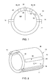
- the turbine casing 10 includes a first or lower hemispherical turbine casing shell (hereinafter referred to as “a lower turbine casing shell”) 11, a second or upper hemispherical turbine casing shell (hereinafter referred to as “an upper turbine casing shell”) 12 and at least one service wedge 30.
- the upper turbine casing shell 12 is configured to be removably coupled to the lower turbine casing shell 11 by fastening elements arrayed along horizontal joints 13 and 14.
- the process of removably coupling the upper turbine casing shell 12 to the lower turbine casing shell 11 is resource and time intensive and conducted by initially attaching the upper turbine casing shell 12 to a crane specifically designed for lifting turbine casing shell parts.
- the process further includes removing each of the fastening elements along the entire axial length of the horizontal joints 13 and 14 so that the upper turbine casing shell 12 can be lifted from the lower turbine casing shell 11.
- a small (i.e., 2 cm or less) borescope opening 15 may be formed in the upper turbine casing shell 12.
- the borescope opening 15 is closed by a closure element that is threadably secured in the borescope opening 15.
- the closure element may be removed from the borescope opening 15 by rotation of the closure element about the radial dimension.
- the borescope opening 15 is typically circular and a diameter thereof is required to be maintained at a relatively small scale to reduce stress concentrations on the casing and so that the closure element can register with the threading. Also, the borescope opening 15 need not be larger than the small-diameter borescope itself to avoid unnecessarily reducing the structural strength of the turbine casing 10.
- the diameter of the borescope opening 15 is small, it is generally not possible to conduct complete inspection and repair operations that require greater access to a turbomachine interior than what is provided via the borescope opening 15 (i.e., small to intermediate scale inspections and repairs) without removing the upper turbine casing shell 12 from the lower turbine casing shell. Consequently, small to intermediate scale inspections and repairs are often associated with outsized costs and turbomachine 10 downtime associated with the resource and time intensive removal process described above. Accordingly, at least one of the upper and lower turbine casing shells 12 and 11 is formed to define an access slot 20 in which the service wedge 30 is sized to fit. The service wedge 30 can therefore be removably installed with respect to the access slot 20 by manual procedures that can be executed quickly or at least more quickly than the full upper turbine casing shell 12 removal process described above.
- the manual procedures may be conducted with efficiency improvement from hoists or cranes that are generally smaller than those used for full casing shell removal.
- the hoists or cranes needed for full removal must have the capability of lifting several tons or more.
- the hoists or cranes that may be required to assist in the removal of the service wedge need to be capable of lifting substantially less weight (e.g., on the order of several hundred pounds or less).
- the service wedge 30 is installed in the access slot 20.
- the service wedge 30 can be removed from the access slot 20 to allow for small to intermediate scale inspections and repairs without otherwise removing the entire upper turbine casing shell 12 from the lower turbine casing shell 11.
- the access slot 20 thus provides for less costly repairs and inspections and less turbomachine downtime as well.
- the access slot 20 may be defined by one or both of the upper and lower turbine casing shells 12 and 11, the following description will relate to the exemplary case of the access slot 20 being defined by the upper turbine casing shell 12. This is being done for clarity and brevity and is not intended to otherwise limit the scope of the application or the claims.
- the access slot 20 may be defined by the upper turbine casing shell 12 to have a circumferential arc-length of adequate dimensions to allow access to and/or removal of specific internal components yet remain sized for fast and efficient removal. Even if the access slot 20 extends along substantially an entire axial length of the turbine casing 10 (e.g., from forward flange 40 to aft flange 41), the access slot 20 may have a relatively short arc-length and thereby allow the corresponding service wedge 30 to remain correspondingly lightweight.
- the lightweight characteristic of the service wedge 30 permits the service wedge 30 to be lifted out of the access slot 20 manually or by use of the relatively small hoists or cranes.
- the illustrations of the access slot 20 in the figures are merely exemplary and that other larger and smaller access slot 20 shapes and sizes may be employed as long as the corresponding service wedge 30 is sufficiently lightweight to be quickly and efficiently removable by manual or hoist/crane assisted procedures.
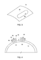
- the access slot 20 is illustrated as having a regular shape, it is to be understood that this is not necessary and that it is possible that the access slot 20 may have a regular, irregular, angled, rounded or otherwise complex shape as shown in FIG. 3 .
- the access slot 20 may be defined along a centerline 120 of the upper turbine casing shell 12 or at an offset position relative to the centerline 120. In either case, the access slot 20 may be but is not required to be defined symmetrically about the centerline 120 to thereby preserve thermal expansion and contraction characteristics of the turbine casing 10.
- the access slot 20 may be defined as multiple access slots 20. In this case, one of the access slots 20 may be defined at a first offset position relative to the centerline 120 and another access slot 20 may be defined at a second offset position on the opposite side of the centerline 120 from the first offset position.
- the first and second offset positions may be defined at or near flexural nodal locations (e.g., the 1:30 and 10:30 positions, respectively) of the upper turbine casing shell 12.
- the service wedge 30 may be provided as multiple service wedges 30 and/or multiple dummy wedges 31.
- each one of the multiple service wedges 30 or dummy wedges 31 is configured to be removably installed in a corresponding one of the multiple access slots 30.
- a dummy wedge may be a casing modification that geometrically mimics the design of the service wedge 30 and provides for similar thermal and mechanical casing responses in a circumferentially symmetric location on the casing to prevent distortions such as out-of-roundness.
- Such a device may also be referred to as "a false flange" or "a false wedge.”
- the service wedge 30 may be secured in the access slot 20 by wedge fastening elements 50.
- the wedge fastening elements 50 include flanges 51 extending from corresponding long-edge portions of both the upper turbine casing shell 12 and the service wedge 30 and combinations of bolts 52 and nuts 53.
- the bolts 52 extend through through-holes defined in the flanges 51 and threadably engage with the nuts 53 to secure the flanges 51 together and to thereby secure the service wedge 30 in the access slot 20.
- the flanges 51 are illustrated in FIG. 4 as extending in the axial dimension along the corresponding long-edge portions of the upper turbine casing shell 12 and the service wedge 30, it is to be understood that this configuration is not required and that other arrangements are possible.
- the flanges 51 could be arranged along the long-edge portions, the short-edge portions or both the long and short-edge portions.
- a number of the bolt/nut combinations may be maintained below a predefined number as long as the service wedge 30 can be secured in the access slot 20 so that the time required to remove the service wedge 30 can remain desirably short.
- the bolt/nut combinations may be arranged so that the bolts 52 extend along the axial or circumferential dimensions (as opposed to the radial dimension).
- the service wedge 30 may be hingeably coupled to the upper turbine casing shell 12 via hinge assembly 60.
- the service wedge 30 may include hinge arm 61 that projects radially outwardly and circumferentially from a side of the service wedge 30 while the upper turbine casing shell 12 may include a guide element 62.
- a boss or hinge-pin 63 may be disposed to extend through the hinge arm 61 and the guide element 62.
- the service wedge 30 can be removed from the access slot 20 by removing any fastening elements in use and then withdrawing the service wedge 30 radially outwardly until the hinge-pin 63 reaches the distal end of the guide element 62.
- the service wedge 30 can be pivoted around the hinge-pin 63 to complete the service wedge 30 removal process.
- the borescope opening 15 may not be required where the access slot 20 is formed. In such cases, the borescope may simply by snaked through the access slot 20 with the service wedge 30 removed. If the borescope is required to be secured in place, appropriate tooling may be provided to do so within the scope of this disclosure.
- multiple service wedges 30 may be removably installed in a single access slot 20.
- the multiple service wedges 30 may be removed as a single unit or one at a time by manual procedures similar to the procedures described above.
- the use of multiple service wedges 30 in a single access slot 20 may permit greater flexibility in access slot 20 sizing as well as greater flexibility in service procedures. That is, for a given service requiring limited access, only one of the multiple service wedges 30 may be removed while all of the multiple service wedges 30 may be removed for more substantial services procedures.
- FIG. 6 illustrates the multiple service wedges 30 being arranged in the access slot 20 in the circumferential dimension
- the multiple service wedges 30 can be arranged in other dimensions.
- the multiple service wedges 30 may be arranged in the circumferential dimension (i.e., in a 2 X 1 matrix, see FIG. 6 ), in the axial dimension (i.e., in a 1 X 2 matrix, see FIG. 7 ) or in the axial and circumferential dimensions (i.e., in a 2 X 2 matrix, see FIG. 8 ).
- a lift efficiency improvement mechanism 100 is provided for use with a service wedge 30 (as described above) that is configured to be removably installed in an access slot 20 of a turbine casing 10.
- the lift efficiency improvement mechanism 100 includes a connector element 101 and a manually transportable lift efficiency improvement device 102, which in some cases, may be a force multiplication device.
- the connector element 101 may be a substantially rigid structural element that is connectable with an outer surface, a flange, a fastening element or some other suitable surface feature of the turbine casing 10 at a location that is proximate to the access slot 20.
- the service wedge 30 may be movable relative to the access slot 20 in a substantially radial direction defined in relation to a radial dimension of the turbine casing 10. Alternatively, as shown in FIGS. 9 and 10 , the service wedge 30 may be rotationally movable about a hinge 103 relative to the access slot 20.
- the lift efficiency improvement device 102 may include a hydraulic or pneumatic jack (see FIG. 9 ) or winch (see FIG. 10 ) and is supportably coupled to the connector element 101 and movably coupled to the service wedge 30.
- the connector element 101 may include an elongate part 1010 that is attachable to the turbine casing 10 and the lift efficiency improvement device 102 may include a pneumatic or hydraulic jacking element 1020 that is operably disposed between the connector element 101 and the service wedge 30.
- FIG. 9 the connector element 101
- winch see FIG. 10
- the connector element 101 may include a support structure 1011 that is attachable to the turbine casing 10 and the lift efficiency improvement device 102 may include a pneumatic or hydraulic winching element 1021 and a cable 1022.
- the cable 1022 is coupled to the service wedge 30 and connected to the pneumatic or hydraulic winching element 1021 whereby the pneumatic or hydraulic winching element 1021 acts on the cable 1022 to control movement of the service wedge 30.
- the lift efficiency improvement 102 is configured to urge the service wedge 30 to move relative to the access slot 20 in response to corresponding operator control movement (i.e., jacking of the pneumatic or hydraulic jacking element 1020).
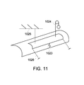
- the lift efficiency improvement device 102 may be provided as at least one of the force multiplication device described above, a force addition device and a guidance tool.
- the lift efficiency improvement device 102 may include at least one of a spring-loading 1023, a counterweight 1024 and a relatively low capacity, manually transportable crane 1025.
- a spring-loading 1023 an elastic element such as a spring may be operably disposed between the turbine casing 10 and the service wedge 30.
- the spring-loading 1023 can be employed to provide a boost to the operator so that the operator is not required to initiate a movement of the service wedge 30 from a stationary position.
- the counterweight 1024 may be attachable to the service wedge 30 when the service wedge 30 is to be removed from the access slot such that the counterweight 1024 effectively reduces the weight of the service wedge 30.
- the low capacity, manually transportable crane 1025 operates in a similar manner as the counterweight and effectively reduces the weight of the service wedge 30.
- the lift efficiency improvement device 102 may include guide rails 1026 that guide the movement of the service wedge 30 during installation and removal of the service wedge 30 with respect to the access slot 20.
- the guide rails 1026 may be provided with relatively shallow angles such that any vertical lifting component of service wedge 30 movement is limited.
- At least one or both of the connector element 101 and the lift efficiency improvement device 102 are manually transportable. That is, at least one or both of the connector element 101 and the lift efficiency improvement device 102 may be sufficiently lightweight to be lifted and carried by an operator to and from the turbine casing 10. Moreover, in accordance with embodiments, at least one or both of the connector element 101 and the lift efficiency improvement device 102 may be sufficiently lightweight to be manually manipulated into position on the turbine casing 10 by the operator without risking damage to the turbine casing 10.
- FIGS. 9-11 can be interchangeable or combinable in various configurations regardless of the arrangements shown in drawings themselves.
Landscapes
- Engineering & Computer Science (AREA)
- Mechanical Engineering (AREA)
- General Engineering & Computer Science (AREA)
- Life Sciences & Earth Sciences (AREA)
- Geology (AREA)
- Structural Engineering (AREA)
- Turbine Rotor Nozzle Sealing (AREA)
- Load-Engaging Elements For Cranes (AREA)
Abstract
Description
- The subject matter disclosed herein relates to a lift efficiency improvement mechanism for turbine casings and, more particularly, to a lift efficiency mechanism for a turbine casing service wedge.
- Gas and steam turbine engines are typically designed with casing/shell splits along the horizontal centerline of the unit. For major maintenance inspections, parts replacements, etc., the upper half casings are normally removed. The disassembly and subsequent re-assembly process is mechanically very involved along with being resource and time intensive. For example, it is necessary to attach the upper half casing to a crane and to remove fastening elements along the entire axial length of both casing/shell splits so that the crane can lift the upper half casing away from the lower half casing.
- For small to medium scale inspection, maintenance, cleaning, repair or replacement operations, the ability of the operator to access the interior of casings/shells is often compromised. As such, it may be necessary for the entire removal process to be conducted even for relatively minor operations if internal access to parts is required. This issue can be especially resource and time intensive particularly as compared to the scope of the relatively small scale maintenance, repair or replacement operations.
- According to one aspect of the invention, a lift efficiency improvement mechanism is provided for use with a service wedge configured to be removably installed in an access slot of a turbine casing. The lift efficiency improvement mechanism includes a connector element, which is connectable with the turbine casing proximate to the access slot and a manually transportable lift efficiency improvement device, which is supportably coupled to the connector element and movably coupled to the service wedge. The lift efficiency improvement device is configured to urge the service wedge to move relative to the access slot responsive to corresponding operator control movement.
- According to another aspect of the invention, a lift efficiency improvement mechanism is provided for use with a service wedge configured to be removably installed in an access slot of a turbine casing. The lift efficiency improvement mechanism includes a connector element, which is connectable with the turbine casing proximate to the access slot and a force multiplication device, which is supportably coupled to the connector element and movably coupled to the service wedge. The connector element and the force multiplication device are manually transportable. The force multiplication device is configured to urge the service wedge to move relative to the access slot responsive to corresponding operator control movement.
- According to yet another aspect of the invention, a method of improving lift efficiency of a service wedge configured to be removably installed in an access slot of a turbine casing is provided. The method includes disposing a connector element in connection with the turbine casing proximate to the access slot, manually transporting a lift efficiency improvement device to the connector element, supportably coupling the lift efficiency improvement device to the connector element, movably coupling the lift efficiency improvement device to the service wedge and employing the lift efficiency improvement device to urge the service wedge to move relative to the access slot.
- These and other advantages and features will become more apparent from the following description taken in conjunction with the drawings.
- The subject matter, which is regarded as the invention, is particularly pointed out and distinctly claimed in the claims at the conclusion of the specification. The foregoing and other features, and advantages of the invention are apparent from the following detailed description taken in conjunction with the accompanying drawings in which:
-
FIG. 1 is an axial view of a turbine casing in accordance with embodiments; -
FIG. 2 is a perspective view of the turbine casing ofFIG. 1 ; -
FIG. 3 is a perspective view of the turbine casing in accordance with alternative embodiments; -
FIG. 4 is an enlarged axial view of a portion of the turbine casing ofFIG. 1 and a service wedge; -
FIG. 5 is an axial view of a service wedge with a hinge; -
FIG. 6 is a schematic perspective view of multiple service wedges in accordance with embodiments; -
FIG. 7 is a schematic perspective view of multiple service wedges in accordance with alternative embodiments; -
FIG. 8 is a schematic perspective view of multiple service wedges in accordance with further alternative embodiments; -
FIG. 9 is a schematic perspective view of a lift efficiency improvement mechanism in accordance with embodiments; -
FIG. 10 is a schematic perspective view of a lift efficiency improvement mechanism in accordance with alternative embodiments; and -
FIG. 11 is a schematic perspective view of lift efficiency improvement mechanisms in accordance with alternative embodiments. - The detailed description explains embodiments of the invention, together with advantages and features, by way of example with reference to the drawings.
- In accordance with aspects, the resources and time intensity of inspections, replacement and repair of rotating and/or stationary parts of gas or steam turbine engines can be dramatically reduced. This may be accomplished by employing at least one or more removable wedge segments as relatively small portions of the complete lower or upper casing or shell. The smaller wedge segments may weigh as little as about 40-1,000 lbs., and can be more efficiently removed than the lower or upper casing or shell during an outage. The wedge segments will allow for direct operator access to blading for more complete inspections, cleaning or repair than can be achieved via a small diameter (typically 2 cm or less) borescope opening. In addition, with proper foresight the blading can be designed for replacement via the access slots formed for the wedge segments to thereby save valuable outage time, reduce lift requirements and afford more complete inspections with complete removal of the upper casings.
- In accordance with further aspects of the invention, the one or more removable wedge segments are manually lifted and removed from the lower or upper casing or shell by an operator who may be using a lift efficiency improvement mechanism. The lift efficiency improvement mechanism can, in some cases, rely upon force addition, guidance tools and force multiplication and may be mountable onto the lower or upper casing or shell and may be hand carried by the operator. In general, the lift efficiency improvement mechanism precludes the need for a large capacity crane.
- With reference to
FIGS. 1, 2 and3 , aturbine casing 10 is provided. Theturbine casing 10 includes a first or lower hemispherical turbine casing shell (hereinafter referred to as "a lower turbine casing shell") 11, a second or upper hemispherical turbine casing shell (hereinafter referred to as "an upper turbine casing shell") 12 and at least oneservice wedge 30. The upperturbine casing shell 12 is configured to be removably coupled to the lowerturbine casing shell 11 by fastening elements arrayed alonghorizontal joints turbine casing shell 12 to the lowerturbine casing shell 11 is resource and time intensive and conducted by initially attaching the upperturbine casing shell 12 to a crane specifically designed for lifting turbine casing shell parts. The process further includes removing each of the fastening elements along the entire axial length of thehorizontal joints turbine casing shell 12 can be lifted from the lowerturbine casing shell 11. - In some conventional cases, it is not necessary to remove the upper
turbine casing shell 12 from the lowerturbine casing shell 11 in order to conduct normal inspection and repair operations. In such cases, access to the interior of theturbine casing 10 may be provided via a small (i.e., 2 cm or less) borescope opening 15 that may be formed in the upperturbine casing shell 12. During turbomachine operational modes, theborescope opening 15 is closed by a closure element that is threadably secured in the borescope opening 15. Thus, the closure element may be removed from the borescope opening 15 by rotation of the closure element about the radial dimension. As such, due to both ease of manufacture and the curvature of theturbine casing 10, theborescope opening 15 is typically circular and a diameter thereof is required to be maintained at a relatively small scale to reduce stress concentrations on the casing and so that the closure element can register with the threading. Also, the borescope opening 15 need not be larger than the small-diameter borescope itself to avoid unnecessarily reducing the structural strength of theturbine casing 10. - Since the diameter of the borescope opening 15 is small, it is generally not possible to conduct complete inspection and repair operations that require greater access to a turbomachine interior than what is provided via the borescope opening 15 (i.e., small to intermediate scale inspections and repairs) without removing the upper
turbine casing shell 12 from the lower turbine casing shell. Consequently, small to intermediate scale inspections and repairs are often associated with outsized costs andturbomachine 10 downtime associated with the resource and time intensive removal process described above. Accordingly, at least one of the upper and lowerturbine casing shells access slot 20 in which theservice wedge 30 is sized to fit. Theservice wedge 30 can therefore be removably installed with respect to theaccess slot 20 by manual procedures that can be executed quickly or at least more quickly than the full upperturbine casing shell 12 removal process described above. - In accordance with aspects, the manual procedures may be conducted with efficiency improvement from hoists or cranes that are generally smaller than those used for full casing shell removal. As the upper and lower
turbine casing shells service wedge 30 is installed in theaccess slot 20. Theservice wedge 30 can be removed from theaccess slot 20 to allow for small to intermediate scale inspections and repairs without otherwise removing the entire upperturbine casing shell 12 from the lowerturbine casing shell 11. Theaccess slot 20 thus provides for less costly repairs and inspections and less turbomachine downtime as well. - Although the
access slot 20 may be defined by one or both of the upper and lowerturbine casing shells access slot 20 being defined by the upperturbine casing shell 12. This is being done for clarity and brevity and is not intended to otherwise limit the scope of the application or the claims. - In accordance with embodiments, the
access slot 20 may be defined by the upperturbine casing shell 12 to have a circumferential arc-length of adequate dimensions to allow access to and/or removal of specific internal components yet remain sized for fast and efficient removal. Even if theaccess slot 20 extends along substantially an entire axial length of the turbine casing 10 (e.g., fromforward flange 40 to aft flange 41), theaccess slot 20 may have a relatively short arc-length and thereby allow thecorresponding service wedge 30 to remain correspondingly lightweight. As theservice wedge 30 is configured to be removably installed in theaccess slot 20 by manual procedures (with or without receiving some efficiency improvement from the aforementioned hoists or cranes), the lightweight characteristic of theservice wedge 30 permits theservice wedge 30 to be lifted out of theaccess slot 20 manually or by use of the relatively small hoists or cranes. - Of course, it is to be understood that the illustrations of the
access slot 20 in the figures are merely exemplary and that other larger andsmaller access slot 20 shapes and sizes may be employed as long as thecorresponding service wedge 30 is sufficiently lightweight to be quickly and efficiently removable by manual or hoist/crane assisted procedures. In addition, although theaccess slot 20 is illustrated as having a regular shape, it is to be understood that this is not necessary and that it is possible that theaccess slot 20 may have a regular, irregular, angled, rounded or otherwise complex shape as shown inFIG. 3 . - The
access slot 20 may be defined along acenterline 120 of the upperturbine casing shell 12 or at an offset position relative to thecenterline 120. In either case, theaccess slot 20 may be but is not required to be defined symmetrically about thecenterline 120 to thereby preserve thermal expansion and contraction characteristics of theturbine casing 10. In the case where theaccess slot 20 is defined at the offset position, theaccess slot 20 may be defined asmultiple access slots 20. In this case, one of theaccess slots 20 may be defined at a first offset position relative to thecenterline 120 and anotheraccess slot 20 may be defined at a second offset position on the opposite side of thecenterline 120 from the first offset position. In accordance with embodiments, the first and second offset positions may be defined at or near flexural nodal locations (e.g., the 1:30 and 10:30 positions, respectively) of the upperturbine casing shell 12. - In the case where the upper
turbine casing shell 12 definesmultiple access slots 20, theservice wedge 30 may be provided asmultiple service wedges 30 and/or multiple dummy wedges 31. In either case, each one of themultiple service wedges 30 or dummy wedges 31 is configured to be removably installed in a corresponding one of themultiple access slots 30. A dummy wedge may be a casing modification that geometrically mimics the design of theservice wedge 30 and provides for similar thermal and mechanical casing responses in a circumferentially symmetric location on the casing to prevent distortions such as out-of-roundness. Such a device may also be referred to as "a false flange" or "a false wedge." - With reference to
FIG. 4 and, in accordance with embodiments, theservice wedge 30 may be secured in theaccess slot 20 bywedge fastening elements 50. Thewedge fastening elements 50 includeflanges 51 extending from corresponding long-edge portions of both the upperturbine casing shell 12 and theservice wedge 30 and combinations ofbolts 52 and nuts 53. Thebolts 52 extend through through-holes defined in theflanges 51 and threadably engage with the nuts 53 to secure theflanges 51 together and to thereby secure theservice wedge 30 in theaccess slot 20. Although theflanges 51 are illustrated inFIG. 4 as extending in the axial dimension along the corresponding long-edge portions of the upperturbine casing shell 12 and theservice wedge 30, it is to be understood that this configuration is not required and that other arrangements are possible. For example, theflanges 51 could be arranged along the long-edge portions, the short-edge portions or both the long and short-edge portions. In any case, a number of the bolt/nut combinations may be maintained below a predefined number as long as theservice wedge 30 can be secured in theaccess slot 20 so that the time required to remove theservice wedge 30 can remain desirably short. In accordance with embodiments, the bolt/nut combinations may be arranged so that thebolts 52 extend along the axial or circumferential dimensions (as opposed to the radial dimension). - With reference to
FIG. 5 , theservice wedge 30 may be hingeably coupled to the upperturbine casing shell 12 viahinge assembly 60. For example, theservice wedge 30 may includehinge arm 61 that projects radially outwardly and circumferentially from a side of theservice wedge 30 while the upperturbine casing shell 12 may include aguide element 62. A boss or hinge-pin 63 may be disposed to extend through thehinge arm 61 and theguide element 62. In such a case, theservice wedge 30 can be removed from theaccess slot 20 by removing any fastening elements in use and then withdrawing theservice wedge 30 radially outwardly until the hinge-pin 63 reaches the distal end of theguide element 62. At this point, theservice wedge 30 can be pivoted around the hinge-pin 63 to complete theservice wedge 30 removal process. - In accordance with further embodiments, it is to be understood that the
borescope opening 15 may not be required where theaccess slot 20 is formed. In such cases, the borescope may simply by snaked through theaccess slot 20 with theservice wedge 30 removed. If the borescope is required to be secured in place, appropriate tooling may be provided to do so within the scope of this disclosure. - With reference to
FIGS. 6-8 and, in accordance with further embodiments,multiple service wedges 30 may be removably installed in asingle access slot 20. In such cases, themultiple service wedges 30 may be removed as a single unit or one at a time by manual procedures similar to the procedures described above. The use ofmultiple service wedges 30 in asingle access slot 20 may permit greater flexibility inaccess slot 20 sizing as well as greater flexibility in service procedures. That is, for a given service requiring limited access, only one of themultiple service wedges 30 may be removed while all of themultiple service wedges 30 may be removed for more substantial services procedures. - Although
FIG. 6 illustrates themultiple service wedges 30 being arranged in theaccess slot 20 in the circumferential dimension, it is to be understood that this is not required and that themultiple service wedges 30 can be arranged in other dimensions. For example, themultiple service wedges 30 may be arranged in the circumferential dimension (i.e., in a 2 X 1 matrix, seeFIG. 6 ), in the axial dimension (i.e., in a 1 X 2 matrix, seeFIG. 7 ) or in the axial and circumferential dimensions (i.e., in a 2 X 2 matrix, seeFIG. 8 ). - With reference to
FIGS. 9 and 10 and, in accordance with further aspects of the invention, a liftefficiency improvement mechanism 100 is provided for use with a service wedge 30 (as described above) that is configured to be removably installed in anaccess slot 20 of aturbine casing 10. The liftefficiency improvement mechanism 100 includes a connector element 101 and a manually transportable lift efficiency improvement device 102, which in some cases, may be a force multiplication device. The connector element 101 may be a substantially rigid structural element that is connectable with an outer surface, a flange, a fastening element or some other suitable surface feature of theturbine casing 10 at a location that is proximate to theaccess slot 20. Theservice wedge 30 may be movable relative to theaccess slot 20 in a substantially radial direction defined in relation to a radial dimension of theturbine casing 10. Alternatively, as shown inFIGS. 9 and 10 , theservice wedge 30 may be rotationally movable about ahinge 103 relative to theaccess slot 20. - Where the lift efficiency improvement device 102 is provided as a force multiplication device, the lift efficiency improvement device 102 may include a hydraulic or pneumatic jack (see
FIG. 9 ) or winch (seeFIG. 10 ) and is supportably coupled to the connector element 101 and movably coupled to theservice wedge 30. In the former case, as shown inFIG. 9 , the connector element 101 may include an elongate part 1010 that is attachable to theturbine casing 10 and the lift efficiency improvement device 102 may include a pneumatic or hydraulic jacking element 1020 that is operably disposed between the connector element 101 and theservice wedge 30. In the latter case, as shown inFIG. 10 , the connector element 101 may include asupport structure 1011 that is attachable to theturbine casing 10 and the lift efficiency improvement device 102 may include a pneumatic orhydraulic winching element 1021 and acable 1022. In this case, thecable 1022 is coupled to theservice wedge 30 and connected to the pneumatic orhydraulic winching element 1021 whereby the pneumatic orhydraulic winching element 1021 acts on thecable 1022 to control movement of theservice wedge 30. In either case, the lift efficiency improvement 102 is configured to urge theservice wedge 30 to move relative to theaccess slot 20 in response to corresponding operator control movement (i.e., jacking of the pneumatic or hydraulic jacking element 1020). - With reference to
FIG. 11 , the lift efficiency improvement device 102 may be provided as at least one of the force multiplication device described above, a force addition device and a guidance tool. - Where the lift efficiency improvement device 102 is provided as a force addition device, the lift efficiency improvement device 102 may include at least one of a spring-
loading 1023, acounterweight 1024 and a relatively low capacity, manuallytransportable crane 1025. In the case of the spring-loading 1023, an elastic element such as a spring may be operably disposed between theturbine casing 10 and theservice wedge 30. When theservice wedge 30 is to be removed from theaccess slot 20 and any fastening elements securing theservice wedge 30 in place are disengaged, the spring-loading 1023 can be employed to provide a boost to the operator so that the operator is not required to initiate a movement of theservice wedge 30 from a stationary position. In the case of thecounterweight 1024, thecounterweight 1024 may be attachable to theservice wedge 30 when theservice wedge 30 is to be removed from the access slot such that thecounterweight 1024 effectively reduces the weight of theservice wedge 30. The low capacity, manuallytransportable crane 1025 operates in a similar manner as the counterweight and effectively reduces the weight of theservice wedge 30. - Where the lift efficiency improvement device 102 is provided as a guidance tool, the lift efficiency improvement device 102 may include
guide rails 1026 that guide the movement of theservice wedge 30 during installation and removal of theservice wedge 30 with respect to theaccess slot 20. In particular, theguide rails 1026 may be provided with relatively shallow angles such that any vertical lifting component ofservice wedge 30 movement is limited. - At least one or both of the connector element 101 and the lift efficiency improvement device 102 are manually transportable. That is, at least one or both of the connector element 101 and the lift efficiency improvement device 102 may be sufficiently lightweight to be lifted and carried by an operator to and from the
turbine casing 10. Moreover, in accordance with embodiments, at least one or both of the connector element 101 and the lift efficiency improvement device 102 may be sufficiently lightweight to be manually manipulated into position on theturbine casing 10 by the operator without risking damage to theturbine casing 10. - It is to be understood that the various embodiments illustrated in the drawings and, particularly,
FIGS. 9-11 can be interchangeable or combinable in various configurations regardless of the arrangements shown in drawings themselves. - While the invention has been described in detail in connection with only a limited number of embodiments, it should be readily understood that the invention is not limited to such disclosed embodiments. Rather, the invention can be modified to incorporate any number of variations, alterations, substitutions or equivalent arrangements not heretofore described, but which are commensurate with the spirit and scope of the invention. Additionally, while various embodiments of the invention have been described, it is to be understood that aspects of the invention may include only some of the described embodiments. Accordingly, the invention is not to be seen as limited by the foregoing description, but is only limited by the scope of the appended claims.
- Various aspects and embodiments of the present invention are defined by the following numbered clauses:
- 1. A lift efficiency improvement mechanism for use with a service wedge configured to be removably installed in an access slot of a turbine casing, the lift efficiency improvement mechanism comprising:
- a connector element, which is connectable with the turbine casing proximate to the access slot; and
- a manually transportable lift efficiency improvement device, which is supportably coupled to the connector element and movably coupled to the service wedge,
- the lift efficiency improvement device being configured to urge the service wedge to move relative to the access slot responsive to corresponding operator control movement.
- 2. The lift efficiency improvement mechanism according to clause 1, wherein the service wedge is radially movable relative to the access slot.
- 3. The lift efficiency improvement mechanism according to any preceding clause, further comprising a hinge by which the service wedge is coupled to the turbine casing.
- 4. The lift efficiency improvement mechanism according to any preceding clause, wherein the service wedge is rotationally movable about the hinge relative to the access slot.
- 5. The lift efficiency improvement mechanism according to any preceding clause 1, wherein the connector element comprises a pad.
- 6. The lift efficiency improvement mechanism according to any preceding clause, wherein the lift efficiency improvement device comprises a force addition device.
- 7. The lift efficiency improvement mechanism according to any preceding clause, wherein the force addition device comprises at least one of a spring-loading, a counter-weight and a crane.
- 8. The lift efficiency improvement mechanism according to any preceding clause, wherein the lift efficiency improvement device comprises a guidance tool.
- 9. The lift efficiency improvement mechanism according to any preceding clause, wherein the lift efficiency improvement device comprises a force multiplication device.
- 10. The lift efficiency improvement mechanism according to any preceding clause, wherein the force multiplication device comprises at least one of a jack and a winch.
- 11. A lift efficiency improvement mechanism for use with a service wedge configured to be removably installed in an access slot of a turbine casing, the lift efficiency improvement mechanism comprising:
- a connector element, which is connectable with the turbine casing proximate to the access slot; and
- a force multiplication device, which is supportably coupled to the connector element and movably coupled to the service wedge,
- the connector element and the force multiplication device being manually transportable, and
- the force multiplication device being configured to urge the service wedge to move relative to the access slot responsive to corresponding operator control movement.
- 12. The lift efficiency improvement mechanism according to any preceding clause, wherein the service wedge is radially movable relative to the access slot.
- 13. The lift efficiency improvement mechanism according to any preceding clause, further comprising a hinge by which the service wedge is coupled to the turbine casing.
- 14. The lift efficiency improvement mechanism according to any preceding clause, wherein the service wedge is rotationally movable about the hinge relative to the access slot.
- 15. The lift efficiency improvement mechanism according to any preceding clause, wherein the connector element comprises a pad.
- 16. The lift efficiency improvement mechanism according to any preceding clause, wherein the force multiplication device comprises a jack.
- 17. The lift efficiency improvement mechanism according to any preceding clause, wherein the force multiplication device comprises a winch.
- 18. A method of improving lift efficiency of a service wedge configured to be removably installed in an access slot of a turbine casing, the method comprising:
- disposing a connector element in connection with the turbine casing proximate to the access slot;
- manually transporting a lift efficiency improvement device to the connector element;
- supportably coupling the lift efficiency improvement device to the connector element;
- movably coupling the lift efficiency improvement device to the service wedge; and
- employing the lift efficiency improvement device to urge the service wedge to move relative to the access slot.
- 19. The method according to any preceding clause, wherein the lift efficiency improvement device comprises at least one of a force addition device, a guidance tool and a force multiplication device.
- 20. The method according to any preceding clause, wherein the employing the lift efficiency improvement device to urge the service wedge to move comprises at least one of urging the service wedge to move linearly and rotationally.
Claims (14)
- A lift efficiency improvement mechanism (100) for use with a service wedge (30) configured to be removably installed in an access slot (20) of a turbine casing (10), the lift efficiency improvement mechanism (100) comprising:a connector element (101), which is connectable with the turbine casing (10) proximate to the access slot (20); anda manually transportable lift efficiency improvement device (102), which is supportably coupled to the connector element (101) and movably coupled to the service wedge (30),the lift efficiency improvement device (102) being configured to urge the service wedge (30) to move relative to the access slot (20) responsive to corresponding operator control movement.
- The lift efficiency improvement mechanism according to claim 1, wherein the lift efficiency improvement device (102) comprises a force addition device.
- The lift efficiency improvement mechanism according to claim 2, wherein the force addition device comprises at least one of a spring-loading (1023), a counter-weight (1024) and a crane (1025).
- The lift efficiency improvement mechanism according to claim 1, 2 or 3, wherein the lift efficiency improvement device comprises a guidance tool (1026).
- The lift efficiency improvement mechanism according to any preceding claim, wherein the lift efficiency improvement device comprises a force multiplication device (1020; 1021).
- A lift efficiency improvement mechanism (100) for use with a service wedge (30) configured to be removably installed in an access slot (20) of a turbine casing (10), the lift efficiency improvement mechanism (100) comprising:a connector element (101), which is connectable with the turbine casing (10) proximate to the access slot (20); anda force multiplication device (1020; 1021), which is supportably coupled to the connector element (101) and movably coupled to the service wedge (30),the connector element (101) and the force multiplication device being manually transportable, andthe force multiplication device being configured to urge the service wedge (30) to move relative to the access slot (20) responsive to corresponding operator control movement.
- The lift efficiency improvement mechanism according to any preceding claim, wherein the service wedge (30) is radially movable relative to the access slot (20).
- The lift efficiency improvement mechanism according to any preceding claim, further comprising a hinge (60) by which the service wedge (30) is coupled to the turbine casing (10).
- The lift efficiency improvement mechanism according to claim 8, wherein the service wedge (30) is rotationally movable about the hinge (60) relative to the access slot (20).
- The lift efficiency improvement mechanism according to any preceding claim, wherein the connector element (101) comprises a pad.
- The lift efficiency improvement mechanism according to any preceding claim, including a force multiplication device comprising at least one of a jack (1020) and a winch (1021).
- A method of improving lift efficiency of a service wedge configured to be removably installed in an access slot of a turbine casing, the method comprising:disposing a connector element in connection with the turbine casing proximate to the access slot;manually transporting a lift efficiency improvement device to the connector element;supportably coupling the lift efficiency improvement device to the connector element;movably coupling the lift efficiency improvement device to the service wedge; andemploying the lift efficiency improvement device to urge the service wedge to move relative to the access slot.
- The method according to claim 12, wherein the lift efficiency improvement device comprises at least one of a force addition device, a guidance tool and a force multiplication device.
- The method according to claim 12 or claim 13, wherein the employing the lift efficiency improvement device to urge the service wedge to move comprises at least one of urging the service wedge to move linearly and rotationally.
Applications Claiming Priority (1)
| Application Number | Priority Date | Filing Date | Title |
|---|---|---|---|
| US13/799,652 US9260281B2 (en) | 2013-03-13 | 2013-03-13 | Lift efficiency improvement mechanism for turbine casing service wedge |
Publications (1)
| Publication Number | Publication Date |
|---|---|
| EP2778353A1 true EP2778353A1 (en) | 2014-09-17 |
Family
ID=50241133
Family Applications (1)
| Application Number | Title | Priority Date | Filing Date |
|---|---|---|---|
| EP14157949.0A Withdrawn EP2778353A1 (en) | 2013-03-13 | 2014-03-05 | Lift efficiency improvement mechanism for turbine casing service wedge |
Country Status (3)
| Country | Link |
|---|---|
| US (1) | US9260281B2 (en) |
| EP (1) | EP2778353A1 (en) |
| JP (1) | JP2014196737A (en) |
Families Citing this family (1)
| Publication number | Priority date | Publication date | Assignee | Title |
|---|---|---|---|---|
| US10502057B2 (en) * | 2015-05-20 | 2019-12-10 | General Electric Company | System and method for blade access in turbomachinery |
Citations (3)
| Publication number | Priority date | Publication date | Assignee | Title |
|---|---|---|---|---|
| CH595546A5 (en) * | 1976-08-13 | 1978-02-15 | Bbc Brown Boveri & Cie | |
| US20110020117A1 (en) * | 2008-03-31 | 2011-01-27 | Makoto Kondo | Casing structure of steam turbine |
| US20120272496A1 (en) * | 2011-04-29 | 2012-11-01 | General Electric Company | System and method for lifting a casing section |
Family Cites Families (49)
| Publication number | Priority date | Publication date | Assignee | Title |
|---|---|---|---|---|
| US2851214A (en) * | 1955-10-12 | 1958-09-09 | Stork Koninklijke Maschf | Axial flow fans or axial flow pumps |
| US3741680A (en) | 1972-04-05 | 1973-06-26 | Avco Corp | Split housing piloting device |
| US3917432A (en) | 1974-11-13 | 1975-11-04 | Gen Electric | Borescope support apparatus |
| US4011017A (en) | 1974-11-13 | 1977-03-08 | General Electric Company | Borescope support apparatus |
| US3936217A (en) | 1975-01-31 | 1976-02-03 | Westinghouse Electric Corporation | Inspection port for turbines |
| US4137006A (en) | 1977-01-26 | 1979-01-30 | K B Southern, Inc. | Composite horizontally split casing |
| US4268221A (en) | 1979-03-28 | 1981-05-19 | United Technologies Corporation | Compressor structure adapted for active clearance control |
| US4412782A (en) | 1979-03-28 | 1983-11-01 | United Technologies Corporation | Full hoop bleed manifolds for longitudinally split compressor cases |
| GB2265418B (en) | 1992-03-26 | 1995-03-08 | Rolls Royce Plc | Gas turbine engine casing |
| US5350136A (en) | 1993-05-14 | 1994-09-27 | United Technologies Corporation | Nacelle arrangement |
| FR2734540B1 (en) | 1995-05-24 | 1997-08-08 | Aerospatiale | AIRCRAFT ENGINE NACELLE HAVING A NACELLE HOOD |
| US5803405A (en) | 1995-06-07 | 1998-09-08 | Northrop Grumman Corporation | Expandable aircraft section |
| US5975463A (en) | 1995-12-21 | 1999-11-02 | Mcdonnell Douglas | Expandable aircraft bay and method |
| US5605438A (en) | 1995-12-29 | 1997-02-25 | General Electric Co. | Casing distortion control for rotating machinery |
| EP1022439B1 (en) | 1999-01-20 | 2004-05-06 | ALSTOM Technology Ltd | Steam or gas turbine casing |
| US6220546B1 (en) | 1999-12-29 | 2001-04-24 | The Boeing Company | Aircraft engine and associated aircraft engine cowl |
| US6471473B1 (en) | 2000-10-17 | 2002-10-29 | Rule Industries, Inc. | Marine in bilge blower |
| US6691019B2 (en) | 2001-12-21 | 2004-02-10 | General Electric Company | Method and system for controlling distortion of turbine case due to thermal variations |
| US6622963B1 (en) | 2002-04-16 | 2003-09-23 | Honeywell International Inc. | System and method for controlling the movement of an aircraft engine cowl door |
| US6663047B1 (en) | 2002-09-20 | 2003-12-16 | Northrop Grumman | Multi-purpose aircraft cavity |
| AU2004217507A1 (en) * | 2003-02-28 | 2004-09-16 | Modec International, L.L.C. | Method of installation of a tension leg platform |
| GB0320371D0 (en) | 2003-08-29 | 2003-10-01 | Rolls Royce Plc | A closure panel arrangement |
| US6868366B1 (en) | 2003-09-16 | 2005-03-15 | General Electric Company | Method for measuring piping forces acting on a turbine casing |
| DE10343627B4 (en) | 2003-09-20 | 2014-03-06 | Eads Deutschland Gmbh | Closure element for an area of the outer skin of an aircraft |
| US7458768B2 (en) | 2005-06-28 | 2008-12-02 | United Technologies Corporation | Borescope inspection port device for gas turbine engine and gas turbine engine using same |
| US7326031B2 (en) | 2005-08-29 | 2008-02-05 | United Technologies Corporation | Access port for dirt removal for gas turbine engine |
| DE102006004785A1 (en) | 2006-02-02 | 2007-08-30 | Alstom Technology Ltd. | flow machine |
| GB2435904B (en) | 2006-03-10 | 2008-08-27 | Rolls Royce Plc | Compressor Casing |
| FR2901244B1 (en) | 2006-05-16 | 2009-01-09 | Airbus France Sas | DEVICE FOR JOINING DOORS OF AN AIRCRAFT NACELLE AND NACELLE EQUIPPED WITH SAID ARTICULATION DEVICE |
| FR2901245B1 (en) | 2006-05-22 | 2008-12-26 | Airbus France Sas | DEVICE FOR JOINING A DOOR OF AN AIRCRAFT NACELLE AND NACELLE EQUIPPED WITH SAID ARTICULATION DEVICE |
| US7721525B2 (en) | 2006-07-19 | 2010-05-25 | Rohr, Inc. | Aircraft engine inlet having zone of deformation |
| FR2905990A1 (en) | 2006-09-20 | 2008-03-21 | Snecma Sa | PROPULSIVE SYSTEM WITH INTEGRATED PYLONE FOR AIRCRAFT. |
| FR2905991B1 (en) | 2006-09-20 | 2012-01-13 | Snecma | INTEGRATED PROPULSIVE SYSTEM COMPRISING A DOUBLE FLOW TURBOREACTOR ENGINE. |
| MX2009003175A (en) | 2006-09-25 | 2009-04-03 | Dresser Rand Co | Access cover for pressurized connector spool. |
| US9126691B2 (en) | 2007-05-30 | 2015-09-08 | United Technologies Corporation | Access door for gas turbine engine components |
| US7843363B2 (en) | 2007-07-12 | 2010-11-30 | Rosemount Aerospace Inc. | Mechanical latch locking detection sensors |
| US8075261B2 (en) | 2007-09-21 | 2011-12-13 | United Technologies Corporation | Gas turbine engine compressor case mounting arrangement |
| US8021109B2 (en) | 2008-01-22 | 2011-09-20 | General Electric Company | Turbine casing with false flange |
| US8210802B2 (en) | 2008-01-22 | 2012-07-03 | General Electric Company | Turbine casing |
| US8047769B2 (en) | 2008-02-07 | 2011-11-01 | General Electric Company | Inspection port plug devices |
| US8568094B2 (en) | 2008-02-28 | 2013-10-29 | Mitsubishi Heavy Industries, Ltd. | Gas turbine and method for opening chamber of gas turbine |
| JP4991600B2 (en) | 2008-02-29 | 2012-08-01 | 株式会社東芝 | Steam turbine |
| US8128353B2 (en) | 2008-09-30 | 2012-03-06 | General Electric Company | Method and apparatus for matching the thermal mass and stiffness of bolted split rings |
| US8246298B2 (en) | 2009-02-26 | 2012-08-21 | General Electric Company | Borescope boss and plug cooling |
| US8210804B2 (en) | 2009-03-20 | 2012-07-03 | Dresser-Rand Company | Slidable cover for casing access port |
| US8109467B2 (en) | 2009-04-24 | 2012-02-07 | United Technologies Corporation | Thrust reverser assembly with shaped drag links |
| US8651809B2 (en) | 2010-10-13 | 2014-02-18 | General Electric Company | Apparatus and method for aligning a turbine casing |
| DE102010051842A1 (en) * | 2010-11-18 | 2012-05-24 | Rolls-Royce Deutschland Ltd & Co Kg | Repair method of a sandwich-type component |
| US20120195746A1 (en) | 2011-01-27 | 2012-08-02 | General Electric Company | Turbomachine service assembly |
-
2013
- 2013-03-13 US US13/799,652 patent/US9260281B2/en not_active Expired - Fee Related
-
2014
- 2014-03-04 JP JP2014041108A patent/JP2014196737A/en active Pending
- 2014-03-05 EP EP14157949.0A patent/EP2778353A1/en not_active Withdrawn
Patent Citations (3)
| Publication number | Priority date | Publication date | Assignee | Title |
|---|---|---|---|---|
| CH595546A5 (en) * | 1976-08-13 | 1978-02-15 | Bbc Brown Boveri & Cie | |
| US20110020117A1 (en) * | 2008-03-31 | 2011-01-27 | Makoto Kondo | Casing structure of steam turbine |
| US20120272496A1 (en) * | 2011-04-29 | 2012-11-01 | General Electric Company | System and method for lifting a casing section |
Also Published As
| Publication number | Publication date |
|---|---|
| JP2014196737A (en) | 2014-10-16 |
| US9260281B2 (en) | 2016-02-16 |
| US20140271092A1 (en) | 2014-09-18 |
Similar Documents
| Publication | Publication Date | Title |
|---|---|---|
| US11572806B2 (en) | Turbine bearing maintenance apparatus and method | |
| KR101234378B1 (en) | Wind turbine generator and maintenance method thereof | |
| CN103443450B (en) | Wind turbine blade bearing removal apparatus and method | |
| US10132243B2 (en) | Mounting and dismounting device for a liner of a gas turbine and a related method | |
| US8984730B2 (en) | System and method for rotating a turbine shell | |
| CN105229904B (en) | Method and apparatus for removing and replacing winding stator core | |
| EP2535530A2 (en) | System and method for adjusting a shroud block in a casing | |
| EP2735709A1 (en) | Turbine casing with service wedge | |
| US10711651B2 (en) | Rotating device for a gas turbine and method for rotating a component | |
| US9260281B2 (en) | Lift efficiency improvement mechanism for turbine casing service wedge | |
| CN113334312A (en) | Tool and method for disassembling blind plate of reactor control rod driving mechanism | |
| EP3961032B1 (en) | Integrated system and method for servicing a component of a wind turbine | |
| CN113858121B (en) | Ship stern tube axis dismounting tool and dismounting method | |
| CN222176599U (en) | Diesel engine piston connecting rod disassembly guide protection device | |
| RU206615U1 (en) | DEVICE FOR MOUNTING AND DISMANTLING OF ATTACHED EQUIPMENT OF A GAS TURBINE ENGINE | |
| CN219620712U (en) | Auxiliary installation and dismounting device for stationary blade assembly of steam turbine | |
| CN223879282U (en) | Large container ship shaft generator rotor lifting device | |
| CN205132987U (en) | Tower crane jib loading boom arm internode wear to sell hydro -cylinder supporting structure | |
| US11118572B2 (en) | Method of remodeling wind turbine power generation facility | |
| CN115163227A (en) | Auxiliary device for disassembly of steam turbine corrugated expansion joint and disassembly method |
Legal Events
| Date | Code | Title | Description |
|---|---|---|---|
| 17P | Request for examination filed |
Effective date: 20140305 |
|
| AK | Designated contracting states |
Kind code of ref document: A1 Designated state(s): AL AT BE BG CH CY CZ DE DK EE ES FI FR GB GR HR HU IE IS IT LI LT LU LV MC MK MT NL NO PL PT RO RS SE SI SK SM TR |
|
| AX | Request for extension of the european patent |
Extension state: BA ME |
|
| PUAI | Public reference made under article 153(3) epc to a published international application that has entered the european phase |
Free format text: ORIGINAL CODE: 0009012 |
|
| R17P | Request for examination filed (corrected) |
Effective date: 20150317 |
|
| RBV | Designated contracting states (corrected) |
Designated state(s): AL AT BE BG CH CY CZ DE DK EE ES FI FR GB GR HR HU IE IS IT LI LT LU LV MC MK MT NL NO PL PT RO RS SE SI SK SM TR |
|
| 17Q | First examination report despatched |
Effective date: 20161221 |
|
| GRAP | Despatch of communication of intention to grant a patent |
Free format text: ORIGINAL CODE: EPIDOSNIGR1 |
|
| RIC1 | Information provided on ipc code assigned before grant |
Ipc: F01D 25/24 20060101ALI20171212BHEP Ipc: F01D 25/28 20060101ALI20171212BHEP Ipc: B66F 19/00 20060101AFI20171212BHEP |
|
| INTG | Intention to grant announced |
Effective date: 20180108 |
|
| GRAS | Grant fee paid |
Free format text: ORIGINAL CODE: EPIDOSNIGR3 |
|
| STAA | Information on the status of an ep patent application or granted ep patent |
Free format text: STATUS: THE APPLICATION IS DEEMED TO BE WITHDRAWN |
|
| 18D | Application deemed to be withdrawn |
Effective date: 20180519 |