EP2778350A2 - Modular turbomachine inlet asembly and related inlet transition section - Google Patents
Modular turbomachine inlet asembly and related inlet transition section Download PDFInfo
- Publication number
- EP2778350A2 EP2778350A2 EP14159599.1A EP14159599A EP2778350A2 EP 2778350 A2 EP2778350 A2 EP 2778350A2 EP 14159599 A EP14159599 A EP 14159599A EP 2778350 A2 EP2778350 A2 EP 2778350A2
- Authority
- EP
- European Patent Office
- Prior art keywords
- inlet
- section
- inlet transition
- sections
- transition section
- Prior art date
- Legal status (The legal status is an assumption and is not a legal conclusion. Google has not performed a legal analysis and makes no representation as to the accuracy of the status listed.)
- Granted
Links
Images


Classifications
-
- F—MECHANICAL ENGINEERING; LIGHTING; HEATING; WEAPONS; BLASTING
- F01—MACHINES OR ENGINES IN GENERAL; ENGINE PLANTS IN GENERAL; STEAM ENGINES
- F01D—NON-POSITIVE DISPLACEMENT MACHINES OR ENGINES, e.g. STEAM TURBINES
- F01D9/00—Stators
- F01D9/02—Nozzles; Nozzle boxes; Stator blades; Guide conduits, e.g. individual nozzles
- F01D9/04—Nozzles; Nozzle boxes; Stator blades; Guide conduits, e.g. individual nozzles forming ring or sector
- F01D9/048—Nozzles; Nozzle boxes; Stator blades; Guide conduits, e.g. individual nozzles forming ring or sector for radial admission
-
- F—MECHANICAL ENGINEERING; LIGHTING; HEATING; WEAPONS; BLASTING
- F01—MACHINES OR ENGINES IN GENERAL; ENGINE PLANTS IN GENERAL; STEAM ENGINES
- F01D—NON-POSITIVE DISPLACEMENT MACHINES OR ENGINES, e.g. STEAM TURBINES
- F01D25/00—Component parts, details, or accessories, not provided for in, or of interest apart from, other groups
- F01D25/24—Casings; Casing parts, e.g. diaphragms, casing fastenings
-
- F—MECHANICAL ENGINEERING; LIGHTING; HEATING; WEAPONS; BLASTING
- F01—MACHINES OR ENGINES IN GENERAL; ENGINE PLANTS IN GENERAL; STEAM ENGINES
- F01D—NON-POSITIVE DISPLACEMENT MACHINES OR ENGINES, e.g. STEAM TURBINES
- F01D25/00—Component parts, details, or accessories, not provided for in, or of interest apart from, other groups
- F01D25/24—Casings; Casing parts, e.g. diaphragms, casing fastenings
- F01D25/246—Fastening of diaphragms or stator-rings
-
- F—MECHANICAL ENGINEERING; LIGHTING; HEATING; WEAPONS; BLASTING
- F01—MACHINES OR ENGINES IN GENERAL; ENGINE PLANTS IN GENERAL; STEAM ENGINES
- F01D—NON-POSITIVE DISPLACEMENT MACHINES OR ENGINES, e.g. STEAM TURBINES
- F01D25/00—Component parts, details, or accessories, not provided for in, or of interest apart from, other groups
- F01D25/24—Casings; Casing parts, e.g. diaphragms, casing fastenings
- F01D25/26—Double casings; Measures against temperature strain in casings
-
- F—MECHANICAL ENGINEERING; LIGHTING; HEATING; WEAPONS; BLASTING
- F01—MACHINES OR ENGINES IN GENERAL; ENGINE PLANTS IN GENERAL; STEAM ENGINES
- F01D—NON-POSITIVE DISPLACEMENT MACHINES OR ENGINES, e.g. STEAM TURBINES
- F01D9/00—Stators
- F01D9/02—Nozzles; Nozzle boxes; Stator blades; Guide conduits, e.g. individual nozzles
- F01D9/023—Transition ducts between combustor cans and first stage of the turbine in gas-turbine engines; their cooling or sealings
-
- F—MECHANICAL ENGINEERING; LIGHTING; HEATING; WEAPONS; BLASTING
- F01—MACHINES OR ENGINES IN GENERAL; ENGINE PLANTS IN GENERAL; STEAM ENGINES
- F01D—NON-POSITIVE DISPLACEMENT MACHINES OR ENGINES, e.g. STEAM TURBINES
- F01D9/00—Stators
- F01D9/06—Fluid supply conduits to nozzles or the like
-
- F—MECHANICAL ENGINEERING; LIGHTING; HEATING; WEAPONS; BLASTING
- F01—MACHINES OR ENGINES IN GENERAL; ENGINE PLANTS IN GENERAL; STEAM ENGINES
- F01D—NON-POSITIVE DISPLACEMENT MACHINES OR ENGINES, e.g. STEAM TURBINES
- F01D9/00—Stators
- F01D9/06—Fluid supply conduits to nozzles or the like
- F01D9/065—Fluid supply or removal conduits traversing the working fluid flow, e.g. for lubrication-, cooling-, or sealing fluids
-
- F—MECHANICAL ENGINEERING; LIGHTING; HEATING; WEAPONS; BLASTING
- F23—COMBUSTION APPARATUS; COMBUSTION PROCESSES
- F23R—GENERATING COMBUSTION PRODUCTS OF HIGH PRESSURE OR HIGH VELOCITY, e.g. GAS-TURBINE COMBUSTION CHAMBERS
- F23R3/00—Continuous combustion chambers using liquid or gaseous fuel
- F23R3/002—Wall structures
-
- F—MECHANICAL ENGINEERING; LIGHTING; HEATING; WEAPONS; BLASTING
- F23—COMBUSTION APPARATUS; COMBUSTION PROCESSES
- F23R—GENERATING COMBUSTION PRODUCTS OF HIGH PRESSURE OR HIGH VELOCITY, e.g. GAS-TURBINE COMBUSTION CHAMBERS
- F23R3/00—Continuous combustion chambers using liquid or gaseous fuel
- F23R3/42—Continuous combustion chambers using liquid or gaseous fuel characterised by the arrangement or form of the flame tubes or combustion chambers
- F23R3/60—Support structures; Attaching or mounting means
-
- F—MECHANICAL ENGINEERING; LIGHTING; HEATING; WEAPONS; BLASTING
- F05—INDEXING SCHEMES RELATING TO ENGINES OR PUMPS IN VARIOUS SUBCLASSES OF CLASSES F01-F04
- F05D—INDEXING SCHEME FOR ASPECTS RELATING TO NON-POSITIVE-DISPLACEMENT MACHINES OR ENGINES, GAS-TURBINES OR JET-PROPULSION PLANTS
- F05D2220/00—Application
- F05D2220/30—Application in turbines
- F05D2220/31—Application in turbines in steam turbines
-
- F—MECHANICAL ENGINEERING; LIGHTING; HEATING; WEAPONS; BLASTING
- F05—INDEXING SCHEMES RELATING TO ENGINES OR PUMPS IN VARIOUS SUBCLASSES OF CLASSES F01-F04
- F05D—INDEXING SCHEME FOR ASPECTS RELATING TO NON-POSITIVE-DISPLACEMENT MACHINES OR ENGINES, GAS-TURBINES OR JET-PROPULSION PLANTS
- F05D2230/00—Manufacture
- F05D2230/50—Building or constructing in particular ways
- F05D2230/51—Building or constructing in particular ways in a modular way, e.g. using several identical or complementary parts or features
-
- F—MECHANICAL ENGINEERING; LIGHTING; HEATING; WEAPONS; BLASTING
- F05—INDEXING SCHEMES RELATING TO ENGINES OR PUMPS IN VARIOUS SUBCLASSES OF CLASSES F01-F04
- F05D—INDEXING SCHEME FOR ASPECTS RELATING TO NON-POSITIVE-DISPLACEMENT MACHINES OR ENGINES, GAS-TURBINES OR JET-PROPULSION PLANTS
- F05D2230/00—Manufacture
- F05D2230/60—Assembly methods
- F05D2230/61—Assembly methods using limited numbers of standard modules which can be adapted by machining
-
- F—MECHANICAL ENGINEERING; LIGHTING; HEATING; WEAPONS; BLASTING
- F05—INDEXING SCHEMES RELATING TO ENGINES OR PUMPS IN VARIOUS SUBCLASSES OF CLASSES F01-F04
- F05D—INDEXING SCHEME FOR ASPECTS RELATING TO NON-POSITIVE-DISPLACEMENT MACHINES OR ENGINES, GAS-TURBINES OR JET-PROPULSION PLANTS
- F05D2240/00—Components
- F05D2240/10—Stators
- F05D2240/14—Casings or housings protecting or supporting assemblies within
Definitions
- the disclosure relates generally to turbomachinery, such as steam turbines, and more particularly, to inlet assemblies for turbomachinery.
- a turbomachine can receive a supply of fluid from a supply conduit via an inlet assembly.
- the inlet assembly can guide the flow from the supply conduit to a rotor of the turbomachine, and can reshape and redirect the flow.
- An inlet transition section of the inlet assembly can guide the flow to an inlet bowl of the assembly.
- the inlet bowl can redirect the flow, such as by turning it through an angle to be received by the rotor.
- the inlet bowl will be connected to the inlet transition section along an edge of the inlet bowl, which results in a polygonal or substantially polygonal connection.
- the inlet transition section can reshape and direct the flow from the circular cross section pipe to the polygonal or substantially polygonal opening to minimize aerodynamic and/or other losses through the transition.
- the inlet assembly is specific to a given supply conduit, or at least to a specific turbomachine model, resulting in a large number of inlet assembly designs.
- aspects of the invention disclosed herein take the form of a turbomachine inlet transition section that includes a substantially circular entry and a reshaping portion beginning at the substantially circular entry.
- the reshaping portion ends in an intermediate region of the inlet transition section having a first substantially polygonal cross section.
- a cross section of the reshaping portion changes from substantially circular at the entry to the first substantially polygonal cross section at the intermediate region while maintaining substantially constant cross sectional area throughout the reshaping portion.
- the inlet transition section also includes a prismoidal portion beginning at the intermediate region and ending at an inlet transition section exit having a second substantially polygonal cross section that is of the same type of polygon as the first substantially polygonal cross section while being of substantially different dimension.
- a modular turbomachine inlet assembly system including a first plurality of inlet transition sections having substantially identical exits of a first size.
- Each inlet transition section includes an entry, and the entries of the first plurality of inlet transition sections includes at least two different sizes.
- Each inlet transition section additionally includes a reshaping portion that is a geometric scale of each other reshaping portion of the first plurality of inlet transition sections.
- the inlet assembly system also includes at least one inlet bowl having an entry of the first size configured for connection to an exit of an inlet transition section of the first plurality of inlet transition sections.
- a modular turbomachine inlet assembly system includes at least two inlet transition sections.
- Each inlet transition section includes a respective substantially circular entry and a respective substantially polygonal exit.
- the at least two inlet transition sections include entries of at least two different diameters, while the substantially polygonal exits have substantially identical dimensions, a first angle between each respective entry and a respective wall of each respective inlet transition section being substantially equal in all of the at least two inlet transition sections.
- the system also includes at least one inlet bowl having a substantially polygonal entry of substantially identical dimension to the substantially polygonal exits of the at least two inlet transition sections.
- Each inlet bowl substantially polygonal entry corresponds to and is configured for attachment to an exit of one of the at least two inlet transition sections.
- aspects of the invention provide methods of making embodiments of the invention disclosed herein, as well as variants of the apparatus, which include and/or implement some or all of the actions and/or features described herein.
- the illustrative aspects of the invention are designed to solve one or more of the problems herein described and/or one or more other problems not discussed.
- a turbomachine can include one or more casings 10 with which an inlet assembly 100 according to embodiments may be used.
- Inlet assembly 100 can take fluid from a supply conduit 12, reshape and/or scale the flow, and redirect the flow into one or more turbomachine casings 10.
- inlet assembly 100 can include an entry 102 configured to be connected to supply conduit 12 and at least one exit 104 configured to transfer fluid to a respective turbomachine casing 10.
- Entry 102 can be part of and/or included in an inlet transition section 110, and exit(s) 104 can be part of and/or included in an inlet bowl 130.
- Flow can be redirected, for example, along a centerline CL of turbomachine casing 10 in embodiments, which can also be a longitudinal axis of inlet bowl 130 and/or turbomachine casing 10.
- inlet transition section 110 can reshape and scale a flow passing from entry 102 to inlet bowl 130, such as with a reshaping portion 112 and a prismoidal portion 114, respectively.
- Entry 102 can have a diameter D, and two sizes of entry 102 are shown in FIG. 2 to illustrate aspects of the invention. It should be noted, however, that only one entry 102 would be used in practice, so that, in the example shown, entry 102 would have either smaller diameter D 1 or larger diameter D 2 , but not two at the same time.
- Reshaping portion 112 can include end walls 116 and a plurality of side walls 118, which can be planar and/or curved as may be suitable and/or desired. Reshaping portion 112 can thus gradually change the cross section of inlet transition section 110 from a circle at entry 102 to a polygon at an intermediate region 120 between reshaping portion 112 and prismoidal portion 114, which can also be viewed as a boundary.
- a cross sectional area of reshaping portion 112 is substantially constant, which can reduce and/or substantially minimize losses through reshaping portion 112.
- Prismoidal portion 114 itself including end walls 122 and side walls 124, can extend between intermediate region 120 and an exit 126 of inlet transition section 110.
- the cross sections at intermediate region 120 and exit 126 can be of the same type of polygon, but of different dimension(s). In addition, changing dimensions of the polygonal cross section can be done gradually so as to minimize losses.
- inlet bowl 130 can include an entry 132 of substantially identical cross section and dimension as inlet transition section exit 126.
- Inlet bowl entry can be connected to inlet transition section exit 126, which, combined with inlet transition section 126, can be construed as a polygonal interface 140.
- the polygonal interface 140 can include additional elements, such as flanges, gaskets, adapters, or the like, to facilitate connection of inlet transition section exit 126 and inlet bowl entry 132.
- inlet bowl entry 132 is formed in an annular portion 134 of inlet bowl 130, while exit(s) 104 of inlet assembly 100 and inlet bowl 130 can be formed in a frustroconical portion 136 of inlet bowl 130.
- entry 132 can be formed in a chordic plane parallel to a longitudinal axis of inlet bowl 130.
- chord plane refers to a plane extending through parallel chords of substantially identical dimension and location on opposite ends 137 of annular portion 134. Fluid thus can enter inlet bowl 130 perpendicular to the longitudinal axis of inlet bowl 130 and/or centerline CL (seen in FIG. 1 ) and can be redirected by inlet bowl 130 to exit inlet bowl 130 in another direction, such as parallel to the longitudinal axis of inlet bowl 130 and/or centerline CL.
- entry 132 can have a substantially polygonal cross section.
- Inlet transition section exit 126 can have a cross section matching that of entry 132, so that both can be polygonal or substantially polygonal, as can a cross section of inlet transition section 110 at intermediate region 120. While the cross sections of inlet transition section exit 126 and inlet bowl entry 132, as well as elements of polygonal interface 140 as may be employed, will have substantially identical dimensions, the cross section of intermediate region 120 can have different dimensions, as will be explained in more detail below.
- Embodiments contemplate the provision of multiple sizes of inlet transition sections 110 that can be used with a single size of inlet bowl 130 to accommodate supply conduits of various diameters, as suggested in FIGS. 2-5 .
- any inlet transition section 110 with an inlet 102 of diameter D within a range of diameters can be used with a particular size of inlet bowl entry 132.
- D 1 is a minimum inlet diameter
- D 2 is a maximum inlet diameter
- inlet transition regions of both diameters and for any diameter therebetween can be provided that will terminate in exits of substantially identical dimension.
- embodiments contemplate direct or geometric scaling of reshaping portion 112.
- dimensions of substantially all parts of reshaping portion 112 increase and/or decrease by a same proportion as between two sizes of inlet transition section 110, but substantially all parts retain the same orientation(s) relative to each other for all inlet transition sections in the range of sizes.
- Each reshaping section 112 can therefore be viewed as a geometric scale of every other reshaping portion 112 in the plurality of inlet transition sections 110.
- geometry of prismoidal portion 114 can be varied to provide a suitable conduit between a given reshaping portion 112 and inlet bowl 130, as will be explained below. This allows a single reshaping portion 112 design or arrangement to be used in the range of sizes, which can reduce design time and cost.
- an inlet transition section 110 with an entry 102 of diameter D 1 can have a first angle ⁇ 1 between entry 102 and reshaping portion end walls 116, and a second angle ⁇ 2 between end walls 116 and prismoidal portion end walls 122 at intermediate region 120.
- inlet transition section 110 with a different diameter D 2 can be used with the same inlet bowl by scaling reshaping portion 112, in which first ⁇ 1 is kept constant.
- end walls 116 have the same orientation for all diameters in a given range of inlet transition section sizes, as seen in FIG. 4 where end walls 116 are substantially parallel.
- a height h reshape of reshaping portion 112 can be unique to each diameter D of inlet 102, so that if diameter D 2 is different from diameter D 1 , h reshape will also be different, and second angle ⁇ 2 must be changed to connect reshaping portion 112 to an inlet bowl 130 of the same size.
- second angle ⁇ 2 an angle ⁇ between each end wall 122 and outer wall 138 is also changed.
- end walls 122 of prismoidal portion 114 can meet an outer wall 138 of inlet bowl annular portion 134 substantially tangentially, as seen in FIG. 4 so that angle ⁇ can be substantially 180°.
- angle ⁇ can be less than or greater than 180°.
- embodiments can impose limits on angle ⁇ for a given installation and/or inlet bowl size, which may affect a range of inlet transition section sizes that can be provided.
- any such limits can be derived using thermodynamic and/or fluid dynamic and/or physical principles known to those skilled in the art and can take into account additional factors, such as height h transition section of inlet transition section 110, height h reshape of reshaping portion 112, height h prismoid of prismoidal portion 114, and/or dimensions of the polygonal cross section used for inlet bowl entry 132 and/or inlet transition section exit 126, though other factors and/or dimensions of inlet assembly 100 may be determined and/or considered as desired and/or appropriate.
- scaling reshaping section 112 as described above can affect additional relationships between elements of inlet transition section 112.
- a third angle ⁇ 3 between entry 102 and side walls 118 can be kept substantially the same for all diameters within a range of inlet transition section sizes.
- a fourth angle ⁇ 4 will be varied accordingly to connect reshaping section 112 to an inlet bowl 130 of a given size.
- an additional angle ⁇ between prismoidal portion side walls 124 and inlet bowl annular portion end walls 137 will also vary.
- a given reshaping geometry scaling can be based on maintaining either first angle or third angle constant in a range of sizes.
- limits can be imposed on additional angle ⁇ in similar fashion to any that might be imposed on angle ⁇ .
- FIGS. 4 and 5 show two inlets simultaneously, one having a smaller entry 102 than the other, yet both meeting the same polygonal cross section at inlet transition section exits 126.
- a single size and configuration of polygonal interface 140 can be used with a plurality of sizes of inlet transition sections 110, or at least with inlet transition sections 110 having a plurality of entry diameters, thus enabling a single polygonal interface 140 to connect a single design of inlet bowl 130 with a plurality of sizes of inlet transition sections 110.
- inlet transition sections 110 could be provided for additional inlet bowl sizes, a respective range for each inlet bowl size or design.
- a single interface size can be used on a range of inlet bowl sizes by maintaining a thickness of inlet bowl annular portion 134 substantially constant for a range of sizes of inlet bowl 130, which can allow a single polygonal interface 140 to be applied by moving inlet bowl entry 132 toward or away from the longitudinal axis and/or centerline CL of inlet bowl 130.
- Embodiments thus contemplate a plurality of polygonal interface sizes combined with a plurality of sizes of inlet transition section 110 and inlet bowl 130 that can accommodate a wide variety of turbomachine installations while reducing a design and inventory burden.
- inlet transition section reshaping portion 112 can change in cross section from circular to polygonal or substantially polygonal, and prismoidal portion 114 can change dimension(s) of the cross section to fit interface 140.
- prismoidal portion 114 can change dimension(s) of the cross section to fit interface 140.
- the example of a polygonal cross section shown in the FIGS. is rectangular, but it should be understood that this is not limiting and that any polygon could be used as appropriate and/or desired.
- a cross sectional area A transition section can be substantially constant through reshaping portion 112.
- an entry 102 of diameter D 2 can have an area of ⁇ 4 ⁇ D 2 2 , and a polygonal or substantially polygonal cross section at intermediate region 120, which can also be viewed as a boundary, can be sized so that its area (W boundary x L boundary for the rectangular example shown) is equal to ⁇ 4 ⁇ D 2 2 , or at least as close as is feasible.
- W boundary x L boundary for the rectangular example shown the area of the polygonal cross section at intermediate region or boundary 120 and those of interface 140 can be different, though the polygon used can be the same.
- W boundary ⁇ W interface in the example shown, and L boundary ⁇ L interface but the cross section in the example is rectangular at both locations.
- An aspect ratio of the cross section can be useful in embodiments, and typically the aspect ratio at intermediate region 120 will be closer to a value of 1 than the aspect ratio at interface 140 since the cross section at intermediate region 120 has substantially the same area as that of the circular cross section of entry 102.
- constraints may be placed on the aspect ratio as a function of transition angles between inlet transition section 110 and entry 102, transition angles between inlet transition section 110 and inlet bowl outer wall 138, flow properties, and/or other factors as may be suitable and/or desired.
Landscapes
- Engineering & Computer Science (AREA)
- Mechanical Engineering (AREA)
- General Engineering & Computer Science (AREA)
- Chemical & Material Sciences (AREA)
- Combustion & Propulsion (AREA)
- Physics & Mathematics (AREA)
- Fluid Mechanics (AREA)
- Structures Of Non-Positive Displacement Pumps (AREA)
- Turbine Rotor Nozzle Sealing (AREA)
Abstract
Description
- The disclosure relates generally to turbomachinery, such as steam turbines, and more particularly, to inlet assemblies for turbomachinery.
- A turbomachine can receive a supply of fluid from a supply conduit via an inlet assembly. The inlet assembly can guide the flow from the supply conduit to a rotor of the turbomachine, and can reshape and redirect the flow. An inlet transition section of the inlet assembly can guide the flow to an inlet bowl of the assembly. The inlet bowl can redirect the flow, such as by turning it through an angle to be received by the rotor. Typically, the inlet bowl will be connected to the inlet transition section along an edge of the inlet bowl, which results in a polygonal or substantially polygonal connection. The inlet transition section can reshape and direct the flow from the circular cross section pipe to the polygonal or substantially polygonal opening to minimize aerodynamic and/or other losses through the transition. However, typically the inlet assembly is specific to a given supply conduit, or at least to a specific turbomachine model, resulting in a large number of inlet assembly designs.
- Aspects of the invention disclosed herein take the form of a turbomachine inlet transition section that includes a substantially circular entry and a reshaping portion beginning at the substantially circular entry. The reshaping portion ends in an intermediate region of the inlet transition section having a first substantially polygonal cross section. A cross section of the reshaping portion changes from substantially circular at the entry to the first substantially polygonal cross section at the intermediate region while maintaining substantially constant cross sectional area throughout the reshaping portion. The inlet transition section also includes a prismoidal portion beginning at the intermediate region and ending at an inlet transition section exit having a second substantially polygonal cross section that is of the same type of polygon as the first substantially polygonal cross section while being of substantially different dimension.
- Another aspect of the inention includes a modular turbomachine inlet assembly system including a first plurality of inlet transition sections having substantially identical exits of a first size. Each inlet transition section includes an entry, and the entries of the first plurality of inlet transition sections includes at least two different sizes. Each inlet transition section additionally includes a reshaping portion that is a geometric scale of each other reshaping portion of the first plurality of inlet transition sections. The inlet assembly system also includes at least one inlet bowl having an entry of the first size configured for connection to an exit of an inlet transition section of the first plurality of inlet transition sections.
- In a further aspect, a modular turbomachine inlet assembly system includes at least two inlet transition sections. Each inlet transition section includes a respective substantially circular entry and a respective substantially polygonal exit. The at least two inlet transition sections include entries of at least two different diameters, while the substantially polygonal exits have substantially identical dimensions, a first angle between each respective entry and a respective wall of each respective inlet transition section being substantially equal in all of the at least two inlet transition sections. The system also includes at least one inlet bowl having a substantially polygonal entry of substantially identical dimension to the substantially polygonal exits of the at least two inlet transition sections. Each inlet bowl substantially polygonal entry corresponds to and is configured for attachment to an exit of one of the at least two inlet transition sections.
- Other aspects of the invention provide methods of making embodiments of the invention disclosed herein, as well as variants of the apparatus, which include and/or implement some or all of the actions and/or features described herein. The illustrative aspects of the invention are designed to solve one or more of the problems herein described and/or one or more other problems not discussed.
- These and other features of the disclosure will be more readily understood from the following detailed description of the various aspects of the invention taken in conjunction with the accompanying drawings that depict various aspects of the invention.
-
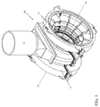
FIG. 1 shows a schematic elevation diagram of a turbomachine including an inlet assembly according to embodiments of the invention disclosed herein. -
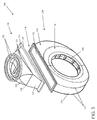
FIG. 2 shows a schematic elevation diagram of an example of an inlet assembly according to embodiments of the invention disclosed herein. -
FIG. 3 shows a schematic elevation diagram of the example shown inFIG. 2 with portions of the inlet assembly separated according to embodiments of the invention disclosed herein are used. -
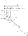
FIG. 4 shows a schematic cross sectional diagram of two examples of portions of inlet assemblies taken along line 4-4 inFIG. 2 according to embodiments of the invention disclosed herein. -
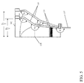
FIG. 5 shows a schematic cross sectional diagram of two examples of portions of inlet assemblies taken along line 5-5 inFIG. 2 according to embodiments of the invention disclosed herein. -
FIG. 6 is a schematic top view of an example of an inlet assembly highlighting cross sections at an entry, intermediate region or boundary, and exit of an inlet transition section according to embodiments of the invention disclosed herein. - It is noted that the drawings may not be to scale. The drawings are intended to depict only typical aspects of the invention, and therefore should not be considered as limiting the scope of the invention. In the drawings, like numbering represents like elements between the drawings.
- The detailed description explains embodiments of the invention, together with advantages and features, by way of example with reference to the drawings.
- With reference to
FIG. 1 , a turbomachine can include one ormore casings 10 with which aninlet assembly 100 according to embodiments may be used.Inlet assembly 100 can take fluid from asupply conduit 12, reshape and/or scale the flow, and redirect the flow into one ormore turbomachine casings 10. Turning toFIG. 2 ,inlet assembly 100 can include anentry 102 configured to be connected to supplyconduit 12 and at least oneexit 104 configured to transfer fluid to arespective turbomachine casing 10.Entry 102 can be part of and/or included in aninlet transition section 110, and exit(s) 104 can be part of and/or included in aninlet bowl 130. Flow can be redirected, for example, along a centerline CL ofturbomachine casing 10 in embodiments, which can also be a longitudinal axis ofinlet bowl 130 and/orturbomachine casing 10. - Turning now to
FIG. 2 ,inlet transition section 110 can reshape and scale a flow passing fromentry 102 toinlet bowl 130, such as with a reshapingportion 112 and aprismoidal portion 114, respectively.Entry 102 can have a diameter D, and two sizes ofentry 102 are shown inFIG. 2 to illustrate aspects of the invention. It should be noted, however, that only oneentry 102 would be used in practice, so that, in the example shown,entry 102 would have either smaller diameter D1 or larger diameter D2, but not two at the same time. - Reshaping
portion 112 can includeend walls 116 and a plurality ofside walls 118, which can be planar and/or curved as may be suitable and/or desired. Reshapingportion 112 can thus gradually change the cross section ofinlet transition section 110 from a circle atentry 102 to a polygon at anintermediate region 120 between reshapingportion 112 andprismoidal portion 114, which can also be viewed as a boundary. In embodiments, a cross sectional area of reshapingportion 112 is substantially constant, which can reduce and/or substantially minimize losses through reshapingportion 112.Prismoidal portion 114, itself includingend walls 122 andside walls 124, can extend betweenintermediate region 120 and anexit 126 ofinlet transition section 110. In embodiments, the cross sections atintermediate region 120 andexit 126 can be of the same type of polygon, but of different dimension(s). In addition, changing dimensions of the polygonal cross section can be done gradually so as to minimize losses. - With particular reference to
FIG. 3 ,inlet bowl 130 can include anentry 132 of substantially identical cross section and dimension as inlettransition section exit 126. Inlet bowl entry can be connected to inlettransition section exit 126, which, combined withinlet transition section 126, can be construed as apolygonal interface 140. In embodiments, thepolygonal interface 140 can include additional elements, such as flanges, gaskets, adapters, or the like, to facilitate connection of inlettransition section exit 126 andinlet bowl entry 132. In embodiments,inlet bowl entry 132 is formed in anannular portion 134 ofinlet bowl 130, while exit(s) 104 ofinlet assembly 100 andinlet bowl 130 can be formed in afrustroconical portion 136 ofinlet bowl 130. In particular,entry 132 can be formed in a chordic plane parallel to a longitudinal axis ofinlet bowl 130. As used herein, "chordic plane" refers to a plane extending through parallel chords of substantially identical dimension and location onopposite ends 137 ofannular portion 134. Fluid thus can enterinlet bowl 130 perpendicular to the longitudinal axis ofinlet bowl 130 and/or centerline CL (seen inFIG. 1 ) and can be redirected byinlet bowl 130 to exitinlet bowl 130 in another direction, such as parallel to the longitudinal axis ofinlet bowl 130 and/or centerline CL. - Where
inlet bowl 130 includes anannular portion 134,entry 132 can have a substantially polygonal cross section. Inlettransition section exit 126, therefore, can have a cross section matching that ofentry 132, so that both can be polygonal or substantially polygonal, as can a cross section ofinlet transition section 110 atintermediate region 120. While the cross sections of inlettransition section exit 126 andinlet bowl entry 132, as well as elements ofpolygonal interface 140 as may be employed, will have substantially identical dimensions, the cross section ofintermediate region 120 can have different dimensions, as will be explained in more detail below. - Embodiments contemplate the provision of multiple sizes of
inlet transition sections 110 that can be used with a single size ofinlet bowl 130 to accommodate supply conduits of various diameters, as suggested inFIGS. 2-5 . In other words, in a plurality ofinlet transition sections 110 having entries orinlets 102 of at least two diameters, anyinlet transition section 110 with aninlet 102 of diameter D within a range of diameters can be used with a particular size ofinlet bowl entry 132. For example, if D1 is a minimum inlet diameter and D2 is a maximum inlet diameter, inlet transition regions of both diameters and for any diameter therebetween can be provided that will terminate in exits of substantially identical dimension. To simplify provision of such a range of sizes, embodiments contemplate direct or geometric scaling of reshapingportion 112. Thus, dimensions of substantially all parts of reshapingportion 112 increase and/or decrease by a same proportion as between two sizes ofinlet transition section 110, but substantially all parts retain the same orientation(s) relative to each other for all inlet transition sections in the range of sizes. Eachreshaping section 112 can therefore be viewed as a geometric scale of every other reshapingportion 112 in the plurality ofinlet transition sections 110. - Since a larger diameter
inlet transition section 110 will have a reshapingportion 112 of greater height than a smaller diameterinlet transition section 110, geometry ofprismoidal portion 114 can be varied to provide a suitable conduit between a given reshapingportion 112 andinlet bowl 130, as will be explained below. This allows asingle reshaping portion 112 design or arrangement to be used in the range of sizes, which can reduce design time and cost. - With reference to
FIG. 4 , aninlet transition section 110 with anentry 102 of diameter D1 can have a first angle θ1 betweenentry 102 and reshapingportion end walls 116, and a second angle θ2 betweenend walls 116 and prismoidalportion end walls 122 atintermediate region 120. According to embodiments,inlet transition section 110 with a different diameter D2 can be used with the same inlet bowl by scaling reshapingportion 112, in which first θ1 is kept constant. As a result, endwalls 116 have the same orientation for all diameters in a given range of inlet transition section sizes, as seen inFIG. 4 whereend walls 116 are substantially parallel. However, a height hreshape of reshapingportion 112 can be unique to each diameter D ofinlet 102, so that if diameter D2 is different from diameter D1, hreshape will also be different, and second angle θ2 must be changed to connect reshapingportion 112 to aninlet bowl 130 of the same size. By changing second angle θ2, an angle φ between eachend wall 122 andouter wall 138 is also changed. In embodiments, endwalls 122 ofprismoidal portion 114 can meet anouter wall 138 of inlet bowlannular portion 134 substantially tangentially, as seen inFIG. 4 so that angle φ can be substantially 180°. However, to accommodate and/or provideinlet transition sections 110 of various sizes for a given inlet bowl size, angle φ can be less than or greater than 180°. To minimize losses in a flow throughinlet assembly 100, embodiments can impose limits on angle φ for a given installation and/or inlet bowl size, which may affect a range of inlet transition section sizes that can be provided. Any such limits can be derived using thermodynamic and/or fluid dynamic and/or physical principles known to those skilled in the art and can take into account additional factors, such as height htransition section ofinlet transition section 110, height hreshape of reshapingportion 112, height hprismoid ofprismoidal portion 114, and/or dimensions of the polygonal cross section used forinlet bowl entry 132 and/or inlettransition section exit 126, though other factors and/or dimensions ofinlet assembly 100 may be determined and/or considered as desired and/or appropriate. - As seen in
FIG. 5 , scalingreshaping section 112 as described above can affect additional relationships between elements ofinlet transition section 112. For example, a third angle θ3 betweenentry 102 andside walls 118 can be kept substantially the same for all diameters within a range of inlet transition section sizes. However, a fourth angle θ4 will be varied accordingly to connect reshapingsection 112 to aninlet bowl 130 of a given size. As a result, an additional angle Ψ between prismoidalportion side walls 124 and inlet bowl annularportion end walls 137 will also vary. It should be noted that a given reshaping geometry scaling can be based on maintaining either first angle or third angle constant in a range of sizes. Similarly, it should also be noted that limits can be imposed on additional angle Ψ in similar fashion to any that might be imposed on angle φ. - The examples described above can be representative of a system and method of standardizing turbomachine inlet assemblies. For example,
FIGS. 4 and5 show two inlets simultaneously, one having asmaller entry 102 than the other, yet both meeting the same polygonal cross section at inlet transition section exits 126. Thus, as described above, a single size and configuration ofpolygonal interface 140 can be used with a plurality of sizes ofinlet transition sections 110, or at least withinlet transition sections 110 having a plurality of entry diameters, thus enabling a singlepolygonal interface 140 to connect a single design ofinlet bowl 130 with a plurality of sizes ofinlet transition sections 110. In addition, additional ranges or pluralities of sizes ofinlet transition sections 110 could be provided for additional inlet bowl sizes, a respective range for each inlet bowl size or design. Further, a single interface size can be used on a range of inlet bowl sizes by maintaining a thickness of inlet bowlannular portion 134 substantially constant for a range of sizes ofinlet bowl 130, which can allow a singlepolygonal interface 140 to be applied by movinginlet bowl entry 132 toward or away from the longitudinal axis and/or centerline CL ofinlet bowl 130. Embodiments thus contemplate a plurality of polygonal interface sizes combined with a plurality of sizes ofinlet transition section 110 andinlet bowl 130 that can accommodate a wide variety of turbomachine installations while reducing a design and inventory burden. - As described above, and with reference to
FIG. 6 , inlet transitionsection reshaping portion 112 can change in cross section from circular to polygonal or substantially polygonal, andprismoidal portion 114 can change dimension(s) of the cross section to fitinterface 140. For the sake of convenience in describing embodiments of the invention, the example of a polygonal cross section shown in the FIGS. is rectangular, but it should be understood that this is not limiting and that any polygon could be used as appropriate and/or desired. In addition to the change in cross section in reshapingportion 112, a cross sectional area Atransition section can be substantially constant through reshapingportion 112. Thus, anentry 102 of diameter D2 can have an area of
intermediate region 120, which can also be viewed as a boundary, can be sized so that its area (Wboundary x Lboundary for the rectangular example shown) is equal to
FIG. 6 , the dimensions of the polygonal cross section at intermediate region orboundary 120 and those ofinterface 140 can be different, though the polygon used can be the same. Thus, Wboundary ≠ Winterface in the example shown, and Lboundary ≠ Linterface, but the cross section in the example is rectangular at both locations. An aspect ratio of the cross section can be useful in embodiments, and typically the aspect ratio atintermediate region 120 will be closer to a value of 1 than the aspect ratio atinterface 140 since the cross section atintermediate region 120 has substantially the same area as that of the circular cross section ofentry 102. In embodiments, constraints may be placed on the aspect ratio as a function of transition angles betweeninlet transition section 110 andentry 102, transition angles betweeninlet transition section 110 and inlet bowlouter wall 138, flow properties, and/or other factors as may be suitable and/or desired. - While the invention has been described in detail in connection with only a limited number of embodiments, it should be readily understood that the invention is not limited to such disclosed embodiments. Rather, the invention can be modified to incorporate any number of variations, alterations, substitutions or equivalent arrangements not heretofore described, but which are commensurate with the spirit and scope of the invention. Additionally, while various embodiments of the invention have been described, it is to be understood that aspects of the invention may include only some of the described embodiments. Accordingly, the invention is not to be seen as limited by the foregoing description, but is only limited by the scope of the appended claims.
- Various aspects and embodiments of the present invention are defined by the following numbered clauses:
- 1. A modular turbomachine inlet assembly system comprising:
- a first plurality of inlet transition sections having substantially identical exits of a first size, each inlet transition section including an entry, the entries of the first plurality of inlet transition sections being of at least two different sizes, and each inlet transition section including a reshaping portion that is a geometric scale of each other reshaping portion of the first plurality of inlet transition sections; and
- at least one inlet bowl including an entry of the first size configured for connection to an exit of an inlet transition section of the first plurality of inlet transition sections.
- 2. The system of clause 1, wherein each inlet transition section reshaping portion includes the respective inlet transition section entry and an intermediate region of the respective inlet transition section, a cross section of the inlet transition section entry having a first shape, a cross section of the intermediate region having a second shape, and a cross sectional area of the reshaping portion being substantially constant throughout an interior of the reshaping portion, the first shape and the second shape being of different types.
- 3. The system of
clause 1 or 2, wherein the first shape is substantially circular and the second shape is substantially polygonal. - 4. The system of any preceding clause, wherein each inlet transition section has a prismoidal portion between the respective intermediate region and the respective inlet transition section exit, the prismoidal portion having a cross section of the second shape at the intermediate region and a cross section of a third shape at the inlet transition section exit, the second shape and the first shape being a same type of shape and differing in at least one dimension.
- 5. The system of any preceding clause, wherein each reshaping portion includes a first angle between the respective inlet transition section entry and a respective reshaping portion wall, the first angle of each reshaping portion being substantially equal to the first angle of every other reshaping portion in the first plurality of inlet transition sections.
- 6. The system of any preceding clause, further comprising a second plurality of inlet transition sections having exits of a second size that differs in at least one dimension from the first size.
- 7. The system of any preceding clause, wherein the at least one inlet bowl includes an inlet bowl with an entry of the second size.
- 8. A modular turbomachine inlet assembly system comprising:
- at least two inlet transition sections, each including a respective substantially circular entry and a respective substantially polygonal exit, the at least two inlet transition sections including entries of at least two different diameters, the substantially polygonal exits of the at least two inlet transition sections having substantially identical dimensions, a first angle between each respective entry and a respective wall of each respective inlet transition section being substantially equal in all of the at least two inlet transition sections; and
- at least one inlet bowl having a substantially polygonal entry of substantially identical dimension to the substantially polygonal exits of the at least two inlet transition sections, each inlet bowl substantially polygonal entry corresponding to and configured for attachment to one of the at least two inlet transition sections.
- 9. The modular turbomachine inlet assembly system of any preceding clause, wherein each inlet transition section has a reshaping portion including the respective substantially circular entry and an intermediate region of the inlet transition section having a first substantially polygonal cross section, and wherein a cross sectional area of the reshaping portion is substantially constant throughout the reshaping portion.
- 10. The modular turbomachine inlet assembly system of any preceding clause, wherein each inlet transition section has a prismoidal portion between an intermediate region of the inlet transition section and the substantially polygonal exit, the prismoidal portion having a first substantially polygonal cross section at the intermediate region, and the inlet bowl substantially polygonal entry having a second substantially polygonal cross section differing from the first substantially polygonal cross section in at least one dimension.
- 11. The modular turbomachine inlet assembly system of any preceding clause, wherein, in an interior of an inlet transition section and a corresponding inlet bowl entry, all angles formed by a part of the inlet assembly meeting another part of the inlet assembly along a direction of flow fall in a range determined at least in part using expected flow conditions and at least one of a diameter of the inlet transition section entry or a dimension of the inlet bowl entry.
- 12. The modular turbomachine inlet assembly system of any preceding clause, wherein the at least two inlet transition sections are a first plurality of inlet transition sections, and a second plurality of inlet transition sections each includes a respective exit that is of substantially identical dimension as compared to all other inlet transition section exits of the second plurality of inlet transition sections, the exits of the second plurality of inlet transition sections differing in at least one dimension from the exits of the first plurality of inlet transition sections.
Claims (9)
- A turbomachine inlet transition section (110) comprising:a substantially circular entry (102);a reshaping portion (112) beginning at the substantially circular entry (102) and ending at an intermediate region (120) having a first substantially polygonal cross section, a cross section of the reshaping portion (112) changing from substantially circular at the entry (102) to the first substantially polygonal cross section at the intermediate region (120) while maintaining substantially constant cross sectional area throughout the reshaping portion (112); anda prismoidal portion (114) beginning at the intermediate region (120) and ending at an inlet transition section exit (126) having a second substantially polygonal cross section, a cross section of the prismoidal portion (114) changing from the first substantially polygonal cross section to the second substantially polygonal cross section, the first and second substantially polygonal cross sections being of the same type of polygon while being of substantially different dimension.
- The inlet transition section of claim 1, wherein the first and second substantially polygonal cross sections are rectangular, the reshaping portion (112) includes opposed end walls (116) and opposed side walls (118) at the intermediate region (120), the prismoidal portion (114) includes opposed end walls (122) and opposed side walls (124), the opposed end walls of the reshaping (116,122) and prismoidal portions (112,114) meet at a first angle in the intermediate region (120), and the opposed side walls (118,124) of the reshaping and prismoidal portions (112,114) meet at a second angle in the intermediate region (120).
- The inlet transition section of claim 1 or 2, wherein an aspect ratio of the first substantially polygonal cross section is closer to one than an aspect ratio of the second substantially polygonal cross section.
- The inlet transition section of any of claims 1 to 3, wherein the inlet transition section (110) includes a first plurality of inlet transition sections having entries (102) of at least two different diameters and each inlet transition section (110) includes a respective exit (104) that is of substantially identical dimension to all other inlet transition section exits (104) of the first plurality of inlet transition sections (110).
- The inlet transition section of claim 4, wherein each respective reshaping portion (110) of the first plurality of inlet transition sections (110) is a geometric scale of every other reshaping portion (112) of the first plurality of inlet transition sections (110).
- The inlet transition section of claim 5, wherein each reshaping portion (112) includes a first angle between a respective entry and a respective wall of the respective reshaping portion (112), and the first angle is of substantially equal value for all of the first plurality of inlet transition sections (110).
- The inlet transition section of claim 5 or 6, wherein the inlet transition section (110) includes a second plurality of inlet transition sections (110) having entries (102) of at least two different diameters and each inlet transition section (110) of the second plurality of inlet transition sections includes a respective exit (126) that is of substantially identical dimension to all other inlet transition section exits (126) of the second plurality of inlet transition sections (110), the exits (126) of the second plurality of inlet transition sections (110) differing in at least one dimension from the exits (126) of the first plurality of inlet transition sections, each respective reshaping portion (112) of the second plurality of inlet transition sections (110) being a geometric scale of each other reshaping portion of the second plurality of inlet transition sections (110).
- The inlet transition section of claim 7, wherein each exit (126) of the first plurality of inlet sections (110) is of a first size configured for connection to at least one inlet bowl (130) each including a respective exit (126) of the first size, and each exit of the second plurality of inlet transition sections (110) is configured for connection to at least one inlet bowl (126) each including an entry (102) of the second size.
- A modular turbomachine inlet assembly system (100) comprising:a first plurality of inlet transition sections (110) as recited in any preceding claim, andat least one inlet bowl (130) including an entry (132) of a first size, equal to the exits (126) of the first plurality of inlet transition sections (110) and configured for connection to an exit (126) of an inlet transition section (110) of the first plurality of inlet transition sections (110).
Applications Claiming Priority (1)
| Application Number | Priority Date | Filing Date | Title |
|---|---|---|---|
| US13/801,425 US9605561B2 (en) | 2013-03-13 | 2013-03-13 | Modular turbomachine inlet assembly and related inlet transition section |
Publications (3)
| Publication Number | Publication Date |
|---|---|
| EP2778350A2 true EP2778350A2 (en) | 2014-09-17 |
| EP2778350A3 EP2778350A3 (en) | 2018-04-04 |
| EP2778350B1 EP2778350B1 (en) | 2019-05-08 |
Family
ID=50272466
Family Applications (1)
| Application Number | Title | Priority Date | Filing Date |
|---|---|---|---|
| EP14159599.1A Active EP2778350B1 (en) | 2013-03-13 | 2014-03-13 | Modular turbomachine inlet assembly and related inlet transition section |
Country Status (5)
| Country | Link |
|---|---|
| US (1) | US9605561B2 (en) |
| EP (1) | EP2778350B1 (en) |
| JP (1) | JP6381932B2 (en) |
| CN (1) | CN203847253U (en) |
| CH (1) | CH707746A2 (en) |
Families Citing this family (3)
| Publication number | Priority date | Publication date | Assignee | Title |
|---|---|---|---|---|
| USD818502S1 (en) | 2015-12-17 | 2018-05-22 | General Electric Company | Turbocharger transition section |
| USD814522S1 (en) * | 2016-06-21 | 2018-04-03 | General Electric Company | Transition section for a turbocharged engine |
| US11002300B2 (en) | 2019-01-30 | 2021-05-11 | General Electric Company | Flow conditioning system |
Family Cites Families (11)
| Publication number | Priority date | Publication date | Assignee | Title |
|---|---|---|---|---|
| US4102598A (en) * | 1975-11-11 | 1978-07-25 | Westinghouse Electric Corp. | Single case low pressure turbine |
| US4863341A (en) | 1988-05-13 | 1989-09-05 | Westinghouse Electric Corp. | Turbine having semi-isolated inlet |
| JP2600164Y2 (en) * | 1991-04-22 | 1999-10-04 | 三菱重工業株式会社 | Exhaust chamber of low pressure turbine |
| US6314894B1 (en) | 2000-08-30 | 2001-11-13 | Jakel Incorporated | Furnace blower housing with integrally formed exhaust transition |
| US6629819B1 (en) | 2002-05-14 | 2003-10-07 | General Electric Company | Steam turbine low pressure inlet flow conditioner and related method |
| JP2005337181A (en) * | 2004-05-28 | 2005-12-08 | Toshiba Corp | Steam turbine |
| DE102008000284A1 (en) | 2007-03-02 | 2008-09-04 | Alstom Technology Ltd. | Power station steam turbine has inner housing of welded construction end forged or rolled steel blade roots |
| JP4950118B2 (en) * | 2008-05-08 | 2012-06-13 | 三菱重工業株式会社 | Steam inlet structure of steam turbine |
| JP5277195B2 (en) * | 2010-03-23 | 2013-08-28 | 株式会社日立製作所 | Turbine inlet structure of double flow steam turbine and double flow steam turbine using the same |
| US8662821B2 (en) | 2010-12-29 | 2014-03-04 | General Electric Company | Removable steam inlet assembly for steam turbine |
| US8790080B2 (en) | 2011-05-06 | 2014-07-29 | General Electric Company | Turbine casing having ledge ring partition aperture |
-
2013
- 2013-03-13 US US13/801,425 patent/US9605561B2/en active Active
-
2014
- 2014-03-10 CH CH00343/14A patent/CH707746A2/en not_active Application Discontinuation
- 2014-03-12 JP JP2014048296A patent/JP6381932B2/en active Active
- 2014-03-13 EP EP14159599.1A patent/EP2778350B1/en active Active
- 2014-03-13 CN CN201420113759.6U patent/CN203847253U/en not_active Expired - Lifetime
Non-Patent Citations (1)
| Title |
|---|
| None |
Also Published As
| Publication number | Publication date |
|---|---|
| JP2014177941A (en) | 2014-09-25 |
| CH707746A2 (en) | 2014-09-15 |
| JP6381932B2 (en) | 2018-08-29 |
| US20140271155A1 (en) | 2014-09-18 |
| EP2778350A3 (en) | 2018-04-04 |
| CN203847253U (en) | 2014-09-24 |
| EP2778350B1 (en) | 2019-05-08 |
| US9605561B2 (en) | 2017-03-28 |
Similar Documents
| Publication | Publication Date | Title |
|---|---|---|
| US9822793B2 (en) | Centrifugal compressor with twisted return channel vane | |
| EP3092413B1 (en) | Centrifugal compressor impeller with non-linear blade leading edge and associated design method | |
| EP2339115B1 (en) | Turbine rotor assembly and steam turbine | |
| EP2618057A1 (en) | Micromixer of turbine system | |
| BR112014014584B1 (en) | SEPARATION DEVICE, AND, METHOD OF MANUFACTURING A TURBILLONER | |
| US20190277139A1 (en) | Steam turbine apparatus | |
| US9085984B2 (en) | Airfoil | |
| EP2778350B1 (en) | Modular turbomachine inlet assembly and related inlet transition section | |
| EP3536972A1 (en) | Centrifugal compressor and turbocharger | |
| US20080310958A1 (en) | Exhaust casing for a turbomachine | |
| EP2831383B1 (en) | Exhaust diffuser for a gas turbine | |
| US20170198608A1 (en) | Exhaust Hood and Its Flow Guide for Steam Turbine | |
| US10690149B2 (en) | Turbine engine part with non-axisymmetric surface | |
| US20120294722A1 (en) | Hybrid flow blade design | |
| EP3067533B1 (en) | Integral metering feature, system and method | |
| US20130243564A1 (en) | Exhaust diffuser for turbine | |
| US6629819B1 (en) | Steam turbine low pressure inlet flow conditioner and related method | |
| WO2017179384A1 (en) | Bolt fastening structure and turbo-machine using same | |
| US10837450B2 (en) | Compressor rotor blade, compressor, and method for profiling the compressor rotor blade | |
| US8057170B2 (en) | Intermediate casing for a gas turbine engine | |
| EP1953443A1 (en) | Piping | |
| US9683450B2 (en) | Turbine casing inlet assembly construction | |
| EP3267086A1 (en) | Coupling arrangement, a connector for a coupling arrangement and a duct comprising a coupling arrangement | |
| US20150013344A1 (en) | Tube | |
| CN204239924U (en) | A kind of engine oil tube assembly |
Legal Events
| Date | Code | Title | Description |
|---|---|---|---|
| 17P | Request for examination filed |
Effective date: 20140313 |
|
| AK | Designated contracting states |
Kind code of ref document: A2 Designated state(s): AL AT BE BG CH CY CZ DE DK EE ES FI FR GB GR HR HU IE IS IT LI LT LU LV MC MK MT NL NO PL PT RO RS SE SI SK SM TR |
|
| AX | Request for extension of the european patent |
Extension state: BA ME |
|
| PUAI | Public reference made under article 153(3) epc to a published international application that has entered the european phase |
Free format text: ORIGINAL CODE: 0009012 |
|
| REG | Reference to a national code |
Ref country code: DE Ref legal event code: R079 Ref document number: 602014046112 Country of ref document: DE Free format text: PREVIOUS MAIN CLASS: F01D0009020000 Ipc: F01D0009040000 |
|
| PUAL | Search report despatched |
Free format text: ORIGINAL CODE: 0009013 |
|
| AK | Designated contracting states |
Kind code of ref document: A3 Designated state(s): AL AT BE BG CH CY CZ DE DK EE ES FI FR GB GR HR HU IE IS IT LI LT LU LV MC MK MT NL NO PL PT RO RS SE SI SK SM TR |
|
| AX | Request for extension of the european patent |
Extension state: BA ME |
|
| RIC1 | Information provided on ipc code assigned before grant |
Ipc: F01D 9/04 20060101AFI20180301BHEP Ipc: F01D 9/06 20060101ALI20180301BHEP Ipc: F01D 25/26 20060101ALI20180301BHEP |
|
| STAA | Information on the status of an ep patent application or granted ep patent |
Free format text: STATUS: REQUEST FOR EXAMINATION WAS MADE |
|
| R17P | Request for examination filed (corrected) |
Effective date: 20181004 |
|
| RBV | Designated contracting states (corrected) |
Designated state(s): AL AT BE BG CH CY CZ DE DK EE ES FI FR GB GR HR HU IE IS IT LI LT LU LV MC MK MT NL NO PL PT RO RS SE SI SK SM TR |
|
| GRAP | Despatch of communication of intention to grant a patent |
Free format text: ORIGINAL CODE: EPIDOSNIGR1 |
|
| STAA | Information on the status of an ep patent application or granted ep patent |
Free format text: STATUS: GRANT OF PATENT IS INTENDED |
|
| INTG | Intention to grant announced |
Effective date: 20181221 |
|
| GRAS | Grant fee paid |
Free format text: ORIGINAL CODE: EPIDOSNIGR3 |
|
| GRAA | (expected) grant |
Free format text: ORIGINAL CODE: 0009210 |
|
| STAA | Information on the status of an ep patent application or granted ep patent |
Free format text: STATUS: THE PATENT HAS BEEN GRANTED |
|
| AK | Designated contracting states |
Kind code of ref document: B1 Designated state(s): AL AT BE BG CH CY CZ DE DK EE ES FI FR GB GR HR HU IE IS IT LI LT LU LV MC MK MT NL NO PL PT RO RS SE SI SK SM TR |
|
| REG | Reference to a national code |
Ref country code: GB Ref legal event code: FG4D |
|
| REG | Reference to a national code |
Ref country code: CH Ref legal event code: EP Ref country code: AT Ref legal event code: REF Ref document number: 1130415 Country of ref document: AT Kind code of ref document: T Effective date: 20190515 |
|
| REG | Reference to a national code |
Ref country code: DE Ref legal event code: R096 Ref document number: 602014046112 Country of ref document: DE Ref country code: IE Ref legal event code: FG4D |
|
| REG | Reference to a national code |
Ref country code: NL Ref legal event code: MP Effective date: 20190508 |
|
| REG | Reference to a national code |
Ref country code: LT Ref legal event code: MG4D |
|
| PG25 | Lapsed in a contracting state [announced via postgrant information from national office to epo] |
Ref country code: LT Free format text: LAPSE BECAUSE OF FAILURE TO SUBMIT A TRANSLATION OF THE DESCRIPTION OR TO PAY THE FEE WITHIN THE PRESCRIBED TIME-LIMIT Effective date: 20190508 Ref country code: HR Free format text: LAPSE BECAUSE OF FAILURE TO SUBMIT A TRANSLATION OF THE DESCRIPTION OR TO PAY THE FEE WITHIN THE PRESCRIBED TIME-LIMIT Effective date: 20190508 Ref country code: NL Free format text: LAPSE BECAUSE OF FAILURE TO SUBMIT A TRANSLATION OF THE DESCRIPTION OR TO PAY THE FEE WITHIN THE PRESCRIBED TIME-LIMIT Effective date: 20190508 Ref country code: FI Free format text: LAPSE BECAUSE OF FAILURE TO SUBMIT A TRANSLATION OF THE DESCRIPTION OR TO PAY THE FEE WITHIN THE PRESCRIBED TIME-LIMIT Effective date: 20190508 Ref country code: AL Free format text: LAPSE BECAUSE OF FAILURE TO SUBMIT A TRANSLATION OF THE DESCRIPTION OR TO PAY THE FEE WITHIN THE PRESCRIBED TIME-LIMIT Effective date: 20190508 Ref country code: ES Free format text: LAPSE BECAUSE OF FAILURE TO SUBMIT A TRANSLATION OF THE DESCRIPTION OR TO PAY THE FEE WITHIN THE PRESCRIBED TIME-LIMIT Effective date: 20190508 Ref country code: PT Free format text: LAPSE BECAUSE OF FAILURE TO SUBMIT A TRANSLATION OF THE DESCRIPTION OR TO PAY THE FEE WITHIN THE PRESCRIBED TIME-LIMIT Effective date: 20190908 Ref country code: SE Free format text: LAPSE BECAUSE OF FAILURE TO SUBMIT A TRANSLATION OF THE DESCRIPTION OR TO PAY THE FEE WITHIN THE PRESCRIBED TIME-LIMIT Effective date: 20190508 Ref country code: NO Free format text: LAPSE BECAUSE OF FAILURE TO SUBMIT A TRANSLATION OF THE DESCRIPTION OR TO PAY THE FEE WITHIN THE PRESCRIBED TIME-LIMIT Effective date: 20190808 |
|
| PG25 | Lapsed in a contracting state [announced via postgrant information from national office to epo] |
Ref country code: GR Free format text: LAPSE BECAUSE OF FAILURE TO SUBMIT A TRANSLATION OF THE DESCRIPTION OR TO PAY THE FEE WITHIN THE PRESCRIBED TIME-LIMIT Effective date: 20190809 Ref country code: LV Free format text: LAPSE BECAUSE OF FAILURE TO SUBMIT A TRANSLATION OF THE DESCRIPTION OR TO PAY THE FEE WITHIN THE PRESCRIBED TIME-LIMIT Effective date: 20190508 Ref country code: BG Free format text: LAPSE BECAUSE OF FAILURE TO SUBMIT A TRANSLATION OF THE DESCRIPTION OR TO PAY THE FEE WITHIN THE PRESCRIBED TIME-LIMIT Effective date: 20190808 Ref country code: RS Free format text: LAPSE BECAUSE OF FAILURE TO SUBMIT A TRANSLATION OF THE DESCRIPTION OR TO PAY THE FEE WITHIN THE PRESCRIBED TIME-LIMIT Effective date: 20190508 |
|
| REG | Reference to a national code |
Ref country code: AT Ref legal event code: MK05 Ref document number: 1130415 Country of ref document: AT Kind code of ref document: T Effective date: 20190508 |
|
| PG25 | Lapsed in a contracting state [announced via postgrant information from national office to epo] |
Ref country code: EE Free format text: LAPSE BECAUSE OF FAILURE TO SUBMIT A TRANSLATION OF THE DESCRIPTION OR TO PAY THE FEE WITHIN THE PRESCRIBED TIME-LIMIT Effective date: 20190508 Ref country code: AT Free format text: LAPSE BECAUSE OF FAILURE TO SUBMIT A TRANSLATION OF THE DESCRIPTION OR TO PAY THE FEE WITHIN THE PRESCRIBED TIME-LIMIT Effective date: 20190508 Ref country code: RO Free format text: LAPSE BECAUSE OF FAILURE TO SUBMIT A TRANSLATION OF THE DESCRIPTION OR TO PAY THE FEE WITHIN THE PRESCRIBED TIME-LIMIT Effective date: 20190508 Ref country code: CZ Free format text: LAPSE BECAUSE OF FAILURE TO SUBMIT A TRANSLATION OF THE DESCRIPTION OR TO PAY THE FEE WITHIN THE PRESCRIBED TIME-LIMIT Effective date: 20190508 Ref country code: SK Free format text: LAPSE BECAUSE OF FAILURE TO SUBMIT A TRANSLATION OF THE DESCRIPTION OR TO PAY THE FEE WITHIN THE PRESCRIBED TIME-LIMIT Effective date: 20190508 Ref country code: DK Free format text: LAPSE BECAUSE OF FAILURE TO SUBMIT A TRANSLATION OF THE DESCRIPTION OR TO PAY THE FEE WITHIN THE PRESCRIBED TIME-LIMIT Effective date: 20190508 |
|
| REG | Reference to a national code |
Ref country code: DE Ref legal event code: R097 Ref document number: 602014046112 Country of ref document: DE |
|
| PG25 | Lapsed in a contracting state [announced via postgrant information from national office to epo] |
Ref country code: SM Free format text: LAPSE BECAUSE OF FAILURE TO SUBMIT A TRANSLATION OF THE DESCRIPTION OR TO PAY THE FEE WITHIN THE PRESCRIBED TIME-LIMIT Effective date: 20190508 Ref country code: IT Free format text: LAPSE BECAUSE OF FAILURE TO SUBMIT A TRANSLATION OF THE DESCRIPTION OR TO PAY THE FEE WITHIN THE PRESCRIBED TIME-LIMIT Effective date: 20190508 |
|
| PLBE | No opposition filed within time limit |
Free format text: ORIGINAL CODE: 0009261 |
|
| STAA | Information on the status of an ep patent application or granted ep patent |
Free format text: STATUS: NO OPPOSITION FILED WITHIN TIME LIMIT |
|
| PG25 | Lapsed in a contracting state [announced via postgrant information from national office to epo] |
Ref country code: TR Free format text: LAPSE BECAUSE OF FAILURE TO SUBMIT A TRANSLATION OF THE DESCRIPTION OR TO PAY THE FEE WITHIN THE PRESCRIBED TIME-LIMIT Effective date: 20190508 |
|
| 26N | No opposition filed |
Effective date: 20200211 |
|
| PG25 | Lapsed in a contracting state [announced via postgrant information from national office to epo] |
Ref country code: PL Free format text: LAPSE BECAUSE OF FAILURE TO SUBMIT A TRANSLATION OF THE DESCRIPTION OR TO PAY THE FEE WITHIN THE PRESCRIBED TIME-LIMIT Effective date: 20190508 |
|
| PG25 | Lapsed in a contracting state [announced via postgrant information from national office to epo] |
Ref country code: SI Free format text: LAPSE BECAUSE OF FAILURE TO SUBMIT A TRANSLATION OF THE DESCRIPTION OR TO PAY THE FEE WITHIN THE PRESCRIBED TIME-LIMIT Effective date: 20190508 |
|
| PG25 | Lapsed in a contracting state [announced via postgrant information from national office to epo] |
Ref country code: MC Free format text: LAPSE BECAUSE OF FAILURE TO SUBMIT A TRANSLATION OF THE DESCRIPTION OR TO PAY THE FEE WITHIN THE PRESCRIBED TIME-LIMIT Effective date: 20190508 |
|
| REG | Reference to a national code |
Ref country code: CH Ref legal event code: PL |
|
| REG | Reference to a national code |
Ref country code: BE Ref legal event code: MM Effective date: 20200331 |
|
| PG25 | Lapsed in a contracting state [announced via postgrant information from national office to epo] |
Ref country code: LU Free format text: LAPSE BECAUSE OF NON-PAYMENT OF DUE FEES Effective date: 20200313 |
|
| PG25 | Lapsed in a contracting state [announced via postgrant information from national office to epo] |
Ref country code: LI Free format text: LAPSE BECAUSE OF NON-PAYMENT OF DUE FEES Effective date: 20200331 Ref country code: FR Free format text: LAPSE BECAUSE OF NON-PAYMENT OF DUE FEES Effective date: 20200331 Ref country code: CH Free format text: LAPSE BECAUSE OF NON-PAYMENT OF DUE FEES Effective date: 20200331 Ref country code: IE Free format text: LAPSE BECAUSE OF NON-PAYMENT OF DUE FEES Effective date: 20200313 |
|
| PG25 | Lapsed in a contracting state [announced via postgrant information from national office to epo] |
Ref country code: BE Free format text: LAPSE BECAUSE OF NON-PAYMENT OF DUE FEES Effective date: 20200331 |
|
| GBPC | Gb: european patent ceased through non-payment of renewal fee |
Effective date: 20200313 |
|
| PG25 | Lapsed in a contracting state [announced via postgrant information from national office to epo] |
Ref country code: GB Free format text: LAPSE BECAUSE OF NON-PAYMENT OF DUE FEES Effective date: 20200313 |
|
| PG25 | Lapsed in a contracting state [announced via postgrant information from national office to epo] |
Ref country code: MT Free format text: LAPSE BECAUSE OF FAILURE TO SUBMIT A TRANSLATION OF THE DESCRIPTION OR TO PAY THE FEE WITHIN THE PRESCRIBED TIME-LIMIT Effective date: 20190508 Ref country code: CY Free format text: LAPSE BECAUSE OF FAILURE TO SUBMIT A TRANSLATION OF THE DESCRIPTION OR TO PAY THE FEE WITHIN THE PRESCRIBED TIME-LIMIT Effective date: 20190508 |
|
| PG25 | Lapsed in a contracting state [announced via postgrant information from national office to epo] |
Ref country code: MK Free format text: LAPSE BECAUSE OF FAILURE TO SUBMIT A TRANSLATION OF THE DESCRIPTION OR TO PAY THE FEE WITHIN THE PRESCRIBED TIME-LIMIT Effective date: 20190508 Ref country code: IS Free format text: LAPSE BECAUSE OF FAILURE TO SUBMIT A TRANSLATION OF THE DESCRIPTION OR TO PAY THE FEE WITHIN THE PRESCRIBED TIME-LIMIT Effective date: 20190908 |
|
| REG | Reference to a national code |
Ref country code: DE Ref legal event code: R082 Ref document number: 602014046112 Country of ref document: DE Ref country code: DE Ref legal event code: R081 Ref document number: 602014046112 Country of ref document: DE Owner name: GENERAL ELECTRIC TECHNOLOGY GMBH, CH Free format text: FORMER OWNER: GENERAL ELECTRIC COMPANY, SCHENECTADY, NY, US |
|
| PGFP | Annual fee paid to national office [announced via postgrant information from national office to epo] |
Ref country code: DE Payment date: 20260219 Year of fee payment: 13 |