EP2778300A1 - Mixing valve assembly for faucet - Google Patents
Mixing valve assembly for faucet Download PDFInfo
- Publication number
- EP2778300A1 EP2778300A1 EP20140160130 EP14160130A EP2778300A1 EP 2778300 A1 EP2778300 A1 EP 2778300A1 EP 20140160130 EP20140160130 EP 20140160130 EP 14160130 A EP14160130 A EP 14160130A EP 2778300 A1 EP2778300 A1 EP 2778300A1
- Authority
- EP
- European Patent Office
- Prior art keywords
- mixing valve
- coupler
- fluid
- fluid supply
- recited
- Prior art date
- Legal status (The legal status is an assumption and is not a legal conclusion. Google has not performed a legal analysis and makes no representation as to the accuracy of the status listed.)
- Withdrawn
Links
- 239000012530 fluid Substances 0.000 claims abstract description 113
- 238000003780 insertion Methods 0.000 claims abstract description 5
- 230000037431 insertion Effects 0.000 claims abstract description 5
- 230000008878 coupling Effects 0.000 claims description 48
- 238000010168 coupling process Methods 0.000 claims description 48
- 238000005859 coupling reaction Methods 0.000 claims description 48
- 239000000463 material Substances 0.000 claims description 24
- 238000007789 sealing Methods 0.000 claims description 14
- 239000002184 metal Substances 0.000 claims description 6
- 229910052751 metal Inorganic materials 0.000 claims description 6
- 238000000034 method Methods 0.000 claims description 6
- XLYOFNOQVPJJNP-UHFFFAOYSA-N water Substances O XLYOFNOQVPJJNP-UHFFFAOYSA-N 0.000 description 30
- 230000000712 assembly Effects 0.000 description 6
- 238000000429 assembly Methods 0.000 description 6
- 230000000717 retained effect Effects 0.000 description 4
- 239000002131 composite material Substances 0.000 description 3
- 238000005304 joining Methods 0.000 description 3
- 238000012986 modification Methods 0.000 description 3
- 230000004048 modification Effects 0.000 description 3
- RYGMFSIKBFXOCR-UHFFFAOYSA-N Copper Chemical compound [Cu] RYGMFSIKBFXOCR-UHFFFAOYSA-N 0.000 description 2
- 239000004677 Nylon Substances 0.000 description 2
- 230000008901 benefit Effects 0.000 description 2
- 238000004891 communication Methods 0.000 description 2
- 229910052802 copper Inorganic materials 0.000 description 2
- 239000010949 copper Substances 0.000 description 2
- 239000003651 drinking water Substances 0.000 description 2
- 238000004519 manufacturing process Methods 0.000 description 2
- 229920001778 nylon Polymers 0.000 description 2
- 238000012552 review Methods 0.000 description 2
- 229910001220 stainless steel Inorganic materials 0.000 description 2
- 239000010935 stainless steel Substances 0.000 description 2
- 229910001369 Brass Inorganic materials 0.000 description 1
- 229910001340 Leaded brass Inorganic materials 0.000 description 1
- 241001275902 Parabramis pekinensis Species 0.000 description 1
- 230000004075 alteration Effects 0.000 description 1
- 235000012206 bottled water Nutrition 0.000 description 1
- 239000010951 brass Substances 0.000 description 1
- 239000003086 colorant Substances 0.000 description 1
- 238000010276 construction Methods 0.000 description 1
- 238000005520 cutting process Methods 0.000 description 1
- 238000013461 design Methods 0.000 description 1
- 235000020188 drinking water Nutrition 0.000 description 1
- 239000011521 glass Substances 0.000 description 1
- 230000008569 process Effects 0.000 description 1
- 238000006467 substitution reaction Methods 0.000 description 1
- 238000003466 welding Methods 0.000 description 1
Images


Classifications
-
- E—FIXED CONSTRUCTIONS
- E03—WATER SUPPLY; SEWERAGE
- E03C—DOMESTIC PLUMBING INSTALLATIONS FOR FRESH WATER OR WASTE WATER; SINKS
- E03C1/00—Domestic plumbing installations for fresh water or waste water; Sinks
- E03C1/02—Plumbing installations for fresh water
- E03C1/04—Water-basin installations specially adapted to wash-basins or baths
- E03C1/0403—Connecting the supply lines to the tap body
-
- F—MECHANICAL ENGINEERING; LIGHTING; HEATING; WEAPONS; BLASTING
- F16—ENGINEERING ELEMENTS AND UNITS; GENERAL MEASURES FOR PRODUCING AND MAINTAINING EFFECTIVE FUNCTIONING OF MACHINES OR INSTALLATIONS; THERMAL INSULATION IN GENERAL
- F16K—VALVES; TAPS; COCKS; ACTUATING-FLOATS; DEVICES FOR VENTING OR AERATING
- F16K11/00—Multiple-way valves, e.g. mixing valves; Pipe fittings incorporating such valves
-
- F—MECHANICAL ENGINEERING; LIGHTING; HEATING; WEAPONS; BLASTING
- F16—ENGINEERING ELEMENTS AND UNITS; GENERAL MEASURES FOR PRODUCING AND MAINTAINING EFFECTIVE FUNCTIONING OF MACHINES OR INSTALLATIONS; THERMAL INSULATION IN GENERAL
- F16K—VALVES; TAPS; COCKS; ACTUATING-FLOATS; DEVICES FOR VENTING OR AERATING
- F16K19/00—Arrangements of valves and flow lines specially adapted for mixing fluids
-
- F—MECHANICAL ENGINEERING; LIGHTING; HEATING; WEAPONS; BLASTING
- F16—ENGINEERING ELEMENTS AND UNITS; GENERAL MEASURES FOR PRODUCING AND MAINTAINING EFFECTIVE FUNCTIONING OF MACHINES OR INSTALLATIONS; THERMAL INSULATION IN GENERAL
- F16K—VALVES; TAPS; COCKS; ACTUATING-FLOATS; DEVICES FOR VENTING OR AERATING
- F16K19/00—Arrangements of valves and flow lines specially adapted for mixing fluids
- F16K19/006—Specially adapted for faucets
-
- F—MECHANICAL ENGINEERING; LIGHTING; HEATING; WEAPONS; BLASTING
- F16—ENGINEERING ELEMENTS AND UNITS; GENERAL MEASURES FOR PRODUCING AND MAINTAINING EFFECTIVE FUNCTIONING OF MACHINES OR INSTALLATIONS; THERMAL INSULATION IN GENERAL
- F16L—PIPES; JOINTS OR FITTINGS FOR PIPES; SUPPORTS FOR PIPES, CABLES OR PROTECTIVE TUBING; MEANS FOR THERMAL INSULATION IN GENERAL
- F16L37/00—Couplings of the quick-acting type
-
- F—MECHANICAL ENGINEERING; LIGHTING; HEATING; WEAPONS; BLASTING
- F16—ENGINEERING ELEMENTS AND UNITS; GENERAL MEASURES FOR PRODUCING AND MAINTAINING EFFECTIVE FUNCTIONING OF MACHINES OR INSTALLATIONS; THERMAL INSULATION IN GENERAL
- F16L—PIPES; JOINTS OR FITTINGS FOR PIPES; SUPPORTS FOR PIPES, CABLES OR PROTECTIVE TUBING; MEANS FOR THERMAL INSULATION IN GENERAL
- F16L37/00—Couplings of the quick-acting type
- F16L37/08—Couplings of the quick-acting type in which the connection between abutting or axially overlapping ends is maintained by locking members
- F16L37/12—Couplings of the quick-acting type in which the connection between abutting or axially overlapping ends is maintained by locking members using hooks, pawls, or other movable or insertable locking members
- F16L37/14—Joints secured by inserting between mating surfaces an element, e.g. a piece of wire, a pin, a chain
- F16L37/142—Joints secured by inserting between mating surfaces an element, e.g. a piece of wire, a pin, a chain where the securing element is inserted tangentially
- F16L37/144—Joints secured by inserting between mating surfaces an element, e.g. a piece of wire, a pin, a chain where the securing element is inserted tangentially the securing element being U-shaped
-
- Y—GENERAL TAGGING OF NEW TECHNOLOGICAL DEVELOPMENTS; GENERAL TAGGING OF CROSS-SECTIONAL TECHNOLOGIES SPANNING OVER SEVERAL SECTIONS OF THE IPC; TECHNICAL SUBJECTS COVERED BY FORMER USPC CROSS-REFERENCE ART COLLECTIONS [XRACs] AND DIGESTS
- Y10—TECHNICAL SUBJECTS COVERED BY FORMER USPC
- Y10T—TECHNICAL SUBJECTS COVERED BY FORMER US CLASSIFICATION
- Y10T137/00—Fluid handling
- Y10T137/0318—Processes
- Y10T137/0402—Cleaning, repairing, or assembling
- Y10T137/0491—Valve or valve element assembling, disassembling, or replacing
- Y10T137/0502—Multi way valve
-
- Y—GENERAL TAGGING OF NEW TECHNOLOGICAL DEVELOPMENTS; GENERAL TAGGING OF CROSS-SECTIONAL TECHNOLOGIES SPANNING OVER SEVERAL SECTIONS OF THE IPC; TECHNICAL SUBJECTS COVERED BY FORMER USPC CROSS-REFERENCE ART COLLECTIONS [XRACs] AND DIGESTS
- Y10—TECHNICAL SUBJECTS COVERED BY FORMER USPC
- Y10T—TECHNICAL SUBJECTS COVERED BY FORMER US CLASSIFICATION
- Y10T137/00—Fluid handling
- Y10T137/598—With repair, tapping, assembly, or disassembly means
- Y10T137/6011—Assembling, disassembling, or removing cartridge type valve [e.g., insertable and removable as a unit, etc.]
- Y10T137/6014—Faucet type [e.g., domestic water use, etc.]
-
- Y—GENERAL TAGGING OF NEW TECHNOLOGICAL DEVELOPMENTS; GENERAL TAGGING OF CROSS-SECTIONAL TECHNOLOGIES SPANNING OVER SEVERAL SECTIONS OF THE IPC; TECHNICAL SUBJECTS COVERED BY FORMER USPC CROSS-REFERENCE ART COLLECTIONS [XRACs] AND DIGESTS
- Y10—TECHNICAL SUBJECTS COVERED BY FORMER USPC
- Y10T—TECHNICAL SUBJECTS COVERED BY FORMER US CLASSIFICATION
- Y10T137/00—Fluid handling
- Y10T137/8593—Systems
- Y10T137/86493—Multi-way valve unit
- Y10T137/86815—Multiple inlet with single outlet
-
- Y—GENERAL TAGGING OF NEW TECHNOLOGICAL DEVELOPMENTS; GENERAL TAGGING OF CROSS-SECTIONAL TECHNOLOGIES SPANNING OVER SEVERAL SECTIONS OF THE IPC; TECHNICAL SUBJECTS COVERED BY FORMER USPC CROSS-REFERENCE ART COLLECTIONS [XRACs] AND DIGESTS
- Y10—TECHNICAL SUBJECTS COVERED BY FORMER USPC
- Y10T—TECHNICAL SUBJECTS COVERED BY FORMER US CLASSIFICATION
- Y10T137/00—Fluid handling
- Y10T137/8593—Systems
- Y10T137/86493—Multi-way valve unit
- Y10T137/86815—Multiple inlet with single outlet
- Y10T137/86823—Rotary valve
Definitions
- the present disclosure relates to the field of mixing valve assemblies for faucets.
- a mixing valve typically receives a hot water supply and a cold water supply.
- a mixing valve includes a chamber or space where water from each supply is mixed together.
- a water outlet line directs water out of the mixing valve to a spout or other outlet.
- a mixing valve assembly may also typically include one or two valves which control the amount of water provided by each supply line, thereby controlling the temperature of water in the water outlet, and the flow rate of water through the water outlet.
- Water supply lines may be configured to couple to a mixing valve assembly in a variety of ways.
- copper tubes may be brazed to a valve assembly.
- PEX tubes may be overmolded onto a waterway or valve assembly.
- a stainless steel or nylon braided hose may include a threaded end fitting that threads into a waterway or valve assembly.
- a supply line may be retained within a mixing valve assembly using a mechanical device, such as a clip. Such a configuration is taught, for example, by U.S. Patent Application No. 12/358,696 .
- An end fitting for a water supply line may include a sealing member, such as a rubber o-ring, to provide a water seal between the supply line and a mixing valve assembly.
- a mixing valve for a faucet includes a body configured to receive therein end portions of a fluid supply line and a fluid outlet line, and a coupler.
- the coupler is configured for insertion through a sidewall of the body to engage features of the fluid supply line and the fluid outlet line so as to retain the fluid supply line and the fluid outlet line within the body.
- the body and the coupler are formed from a polymeric material. It may be that the body is formed from a metal. It may be that the coupler has a generally U-shaped configuration and two ends of the U-shaped coupler are configured for receipt within apertures formed in the body. It may be that the mixing valve further comprises a clip that is coupled to an exterior surface of the mixing valve to retain the coupler within the body. It may be that the fluid supply line and the fluid outlet line include end portions having grooves formed in exterior surfaces thereof, and the end portions are configured for engaging with the coupler when the coupler is inserted through the sidewall of the body.
- the end portions of the fluid supply line and the fluid outlet line each comprise a coupling member coupled to a hose, and the features configured to be engaged by the coupler are integrally formed as part of the coupling members.
- the body comprises a first and second aperture for receiving, respectively, the first fluid supply line and a second fluid supply line, and a third aperture for receiving the fluid outlet line.
- the mixing valve comprises two couplers, wherein each of the two couplers are configured for insertion through the sidewall of the coupler at different locations, wherein the two couplers each engage all three of the end portions of the first and second fluid supply lines and the fluid outlet line to retain the end portions of the first and second fluid supply lines and the fluid outlet line within the body.
- the coupling members include a groove, and the grooves receive a sealing member.
- a mixing valve for a faucet includes a body configured to receive therein end portions of a plurality of fluid supply lines and a fluid outline line, and a coupler.
- the coupler is configured to retain all of the fluid supply lines and the fluid outlet line within the body.
- the body and coupler each are formed from a polymeric material. It may be that the body is formed from a metal. It may be that a plurality of couplers retain the fluid supply lines and the fluid outlet line within the body. It may be that the coupler has a generally U-shaped configuration and two ends of the U-shaped coupler are configured for receipt within apertures formed in the body. It may be that the fluid supply lines and the fluid outlet line include end portions having a surface that abuts against an end of the U-shaped coupler when the coupler is inserted through the sidewall of the body.
- a coupling member is coupled to the end portions of the fluid supply lines, and the features configured to abut against an end of the U-shaped coupler are integrally formed on the coupling members. It may be that the coupling members include a radial groove, and the radial grooves are configured to receive a sealing member.
- a mixing valve for a faucet may be assembled by receiving end portions of a fluid supply line and a fluid outline line within apertures of a body of a mixing valve, and inserting a coupler through a sidewall of the body to engage features of the fluid supply line and the fluid outlet line so as to retain the fluid supply line and the fluid outlet line within the body.
- the fluid supply line and the fluid outlet line include end portions having radial grooves formed on exterior surfaces thereof that are configured for engaging with the coupler when the coupler is inserted through the sidewall of the body.
- a mixing valve for a faucet is defined in claim 1.
- Optional features of the mixing valve are the subject of claims 2 to 13.
- a faucet having a mixing valve according to any of claims 1 to 13 is the subject of claim 14.
- a method for assembling a mixing valve for a faucet according to any of claims 1 to 14 is the subject of claim 15
- a faucet assembly 2 includes, among other elements, a faucet spout 3, a spout hub or base 4, a valve assembly, a handle 6, a plurality of fluid supply lines 5, 7, a mixing valve assembly 8, and a valve assembly (not shown) interfacing or engaging with the mixing valve assembly 8.
- the faucet assembly 2 may mount to a sink deck, a countertop, or other mounting surface in any suitable manner.
- the faucet assembly 2 may include two water supply lines, such as supply line 5 and supply line 7 (i.e., one used to carry hot water and one for cold water) that are coupled to a mixing valve 1.
- the supply lines 5, 7 may be configured to withstand a normal operating water pressure of approximately 50 psi. While FIG. 1 shows a particular type of faucet, it should be understood that other types of faucets may be used with the mixing valve assemblies discussed herein according to other exemplary embodiments.
- the mixing valve 1 may be positioned within the spout hub 4.
- the two supply lines 5, 7 are coupled to an inlet end of the mixing valve 1, and may extend downwards toward a mounting surface (not shown) for the faucet assembly 2.
- the mixing valve 1 may be oriented within the spout hub 4 so that a upper surface 23 of the mixing valve 1 is faced toward a valve assembly (not shown).
- the valve assembly may be configured so that water supplied from the supply lines 5, 7 is mixed within the valve assembly. Once the water is mixed within the valve assembly, it may flow toward the faucet spout 3.
- a sealing member (not shown) may be disposed between the valve assembly and the upper surface 23 of the mixing valve 1.
- the sealing member may be used to sealingly couple the valve assembly and the mixing valve 1. While FIG. 1 shows a particular orientation of the mixing valve assembly 8 within the faucet assembly 2, it should be understood that a mixing valve assembly may be arranged in other ways within a faucet assembly.
- a mixing valve may be coupled to a valve assembly through various other means.
- a valve assembly may include a hole used to receive an end proximate the upper surface of a mixing valve.
- the hole in a valve assembly and an end of a mixing valve may be configured to be coupled according to a particular orientation, thereby ensuring the mixing valve is properly positioned with the valve assembly.
- the end of a mixing valve may include a protrusion which is configured to engage a recession of the valve assembly, thereby ensuring that the mixing valve and the valve assembly are engaged in a particular orientation.
- a mixing valve assembly may be mounted or positioned in a location spaced away from a faucet spout.
- a mixing valve assembly may be positioned underneath a sink deck, above a sink deck, or in any other suitable location according to other exemplary embodiments.
- the mixing valve assembly 8 may be used to control the amount of water that flows from the supply lines 5, 7 to the faucet spout 3.
- the mixing valve assembly 8 may include a valve, and the position of the valve over the upper surface 23 may control the flow of fluid from the supply lines 5, 7 to the faucet spout 3.
- the valve may be pivoted so that the supply line 5 (supplying, e.g., hot water), is in fluidic communication with an outlet line (see, e.g., the fluid conduit 11 in FIG. 7 ) while the supply line 7 (supplying, e.g., cold water) is not in fluidic communication with an outlet line.
- a user may control the position of the valve (and therefore, the temperature and flow rate of water flowing through the faucet spout 3) by pivoting the handle 6.
- the mixing valve assembly 8 includes the mixing valve 1, the supply lines 5, 7, at least one U-shaped clip 17 (two of which are shown in FIG. 2 ), an outer clip 31, and a fluid conduit 11 (not illustrated in FIG. 2 , but shown, for example, in FIG. 7 ).
- the mixing valve 1 may include an outlet port (e.g., bore, hole, harbor, etc.), such as an outlet port 10, which includes a receiving end that is configured to receive the fluid conduit 11.
- the mixing valve 1 may include two inlet ports (e.g., bores, holes, harbors, etc.), such as inlet ports 9 and 12.
- the inlet ports 9, 12 may be configured to receive either of the supply lines 5, 7 near a first end portion 37 of the mixing valve 1.
- Each inlet port 9, 12 may include a counterbore so that a proscribed portion of the supply lines 5, 7 are received therein.
- each of the U-shaped clips 17 may be configured to be received within a lateral slot 14, 16 (not shown in FIG. 2 , but shown, for example, in FIG. 4 ) (i.e., an aperture, opening, slit, etc.) disposed within a side wall 15 (not shown in FIG. 2 , but shown, for example, in FIG. 6 ) of the mixing valve 1.
- the mixing valve 1 may include two lateral slots, each of which are openly disposed on opposite sides of the mixing valve.
- the outer clip 31 is configured to couple to a portion of the side wall 15 of the mixing valve 1 and the U-shaped clips 17.
- the outer clip 31 may be configured to retain the U-shaped clips 17 within the mixing valve 1 when the outer clip 31 is coupled to the side wall of the mixing valve 1.
- the inlet ports 9, 12 and the outlet port 10 may be holes that extend through the mixing valve 1. Further, the inlet ports 9, 12 may be defined on an upper side by the upper surface 23 of the mixing valve 1. As shown in FIG. 3 , the inlet ports 9, 12 may be positioned adjacent to each other within the mixing valve 1. Also, the outlet port 10 may be positioned offset from, and between the inlet ports 9, 12. While FIG. 3 shows a particular arrangement of inlet and outlet ports of a mixing valve, it should be understood that inlet and outlet ports for a mixing valve may be arranged in other ways, according to other exemplary embodiments. For example, the outlet port for the mixing valve may linearly aligned with a plurality of inlet ports.
- the mixing valve 1 may be made from 30% glass-filled nylon.
- other materials may be used to make a mixing valve, such as other polymeric materials, a metal, a composite material, or any other suitable material, according to other exemplary embodiments.
- the mixing valve 1 may include various features or elements used to position the mixing valve relative to the spout hub 4 or a valve assembly.
- a plurality of positioning members 13 e.g., protrusions, projections, extensions, locators, etc.
- the positioning member 13 may be configured as a protrusion which is coupled to a generally cylindrical outer surface (i.e., a radial surface) of the mixing valve 1.
- the positioning member 13 may be integrally formed with the mixing valve 1.
- An inner surface of the spout hub 4 (which is not shown) may include a plurality of positioning recesses that are each configured to receive either of the positioning members 13.
- the mixing valve may include a plurality of positioning holes 25, which are disposed within the upper surface 23.
- the positioning holes 25 may be configured to be received by a plurality of positioning protrusions of a facing valve assembly (which is not shown), in order to position the valve assembly onto the mixing valve 1.
- a mixing valve may include other members and features used to position (e.g., orient, align, etc.) the mixing valve within a faucet assembly, according to other exemplary embodiments.
- the mixing valve 1 may include the first end portion 37 that is defined by the inlet ports 9, 12 and the outlet port 10, and an opposite second end portion 38 that is defined by the upper surface 23.
- the mixing valve may be generally cylindrical in the fully assembled state.
- the figures show various types of mixing valves that may be used in a mixing valve assembly, it should be understood that other types of mixing valves may be used with the mixing valve assemblies discussed herein according to other exemplary embodiments.
- the inlet ports 9, 12 of the mixing valve 1 may include at least one lateral slot, such as a lateral slot 14 and a lateral slot 16.
- An opening for each of the lateral slots 14, 16 may be laterally disposed within a side wall 15 of the mixing valve 1.
- the lateral slots 14, 16 may be openly disposed within opposite sides of the mixing valve 1.
- the lateral slots 14, 16 may be openly disposed within one side of the mixing valve 1.
- each of the lateral slots 14, 16 may extend through at least a portion of each inlet port 9, 12 and within at least a portion of the outlet port 10.
- the lateral slot 14 may be positioned essentially vertically below the lateral slot 16, when the receiving ends of the inlet ports 9, 12 (i.e., the portions near the first end 37) are downwardly oriented.
- the lateral slot 14 may be openly disposed on a first side of the mixing valve 1, and the lateral slot 16 may be openly disposed on a second side of the mixing valve 1, which is opposite the first side.
- the lateral slot 16 may be openly disposed on the same side of the mixing valve 1 as the lateral slot 14.
- the mixing valve 1 includes a radial groove 36. As shown in FIG. 5 , the radial groove 36 is disposed vertically between the positioning members 13 and the upper surface 23.
- the radial groove 36 is configured to receive a sealing member, such as an o-ring, (which is not shown) that is configured to sealingly couple an exterior surface of the mixing valve 1 and another element of the mixing valve assembly 8, such as the spout hub 4.
- the sealing member received within radial groove 36 may be used prevent water from leaking beyond the radial groove 36, thereby preventing water from undesirably escaping below the mixing valve assembly 8 when the assembly is provided in a faucet assembly.
- the diameter of the opening of the outlet port 10, which is defined by the upper surface 23 of the mixing valve 1, may be larger than either of the diameters of the openings of the inlet ports 9, 12, which are also defined by the upper surface 23.
- the diameters of the openings of the inlet ports 9, 12 defined by the upper surface 23 may be smaller than the openings defined by the receiving ends of the inlet ports 9, 12.
- the smaller openings of the inlet ports 9, 12 within the upper surface 23 may be used to constrain the supply lines 5, 7. Therefore, the inlet ports 9, 12 may be configured so that the supply lines 5, 7 are not able to extend past the upper surface 23 when the inlet ports 9, 12 are received by the supply lines 5, 7.
- the diameter of the opening of the outlet port 10 defined by the upper surface 23 may be smaller than the opening defined by the receiving end of the outlet port 10. Therefore, the outlet port 10 may be configured so that the fluid conduit 11 is not able to extend past the upper surface 23 when the outlet port 10 is received by the fluid conduit 11.
- FIG. 6 a cross-sectional view of the mixing valve 1 is shown.
- the inlet ports 9, 12 are shown as extending downward through the mixing valve 1.
- the radial groove 36 is shown as being positioned below the protrusions 13, when the upper surface 23 is downwardly facing.
- the lateral slots 14, 16 are shown as being positioned above the protrusions 13, when the upper surface is upwardly facing. Further, the lateral slots 16, 14 extend laterally through the mixing valve.
- the supply lines 5, 7 and the fluid conduit 11 are shown interfacing with the two U-shaped clips 17 as they would within the mixing valve 1 when assembled therein.
- the supply lines 5, 7, and the fluid conduit 11 are configured to be coupled to the U-shaped clips when the supply lines 5, 7 are received within the receiving ends of the inlet ports 9, 12, and the fluid conduit is received within the receiving end of the outlet port 10.
- these elements are shown without the mixing valve 1.
- a coupling such as a coupling 32, 33
- a coupling 34 is coupled to an end of the fluid conduit 11.
- the couplings 32, 33, 34 are intended to be retained therein by the U-shaped clips 17.
- each of the couplings 32, 33, 34 may include a plurality of first radial grooves 20, and a plurality of second radial grooves 22.
- Each second radial groove 22 may be configured to be received by a sealing member, such as an o-ring.
- Each first radial groove 20 of couplings 32, 33 may be configured to be received by two arm portions 18 of each of the U-shaped clips 17.
- the size of the first radial groove 20 of coupling 34 may be configured to be received by at least one arm portion 18 of each of the U-shaped clips 17.
- the size of the first radial grooves 20 and the second radial grooves 22 may be equal.
- the size of the first radial grooves may be smaller or larger than the second radial grooves.
- each of a first radial groove 20 for the couplings 32, 33 may be received by a U-shaped clip 17 from two opposite sides of the mixing valve 1.
- each of the first radial grooves 20 of the couplings 32, 33 may be received by a U-shaped clip from the same side of the mixing valve 1.
- a single U-shaped clip may be configured to simultaneously couple to each of the couplings 32, 33, and 34 when the supply lines 5, 7 are received within the inlet ports 9, 12 and the fluid conduit 11 is received within the outlet port 10.
- each arm portion 18 of the U-shaped clip 17 may be configured to be received within the radial groove 20 of the couplings 32, 33.
- one arm portion 18 of the U-shaped clip may be received within the radial groove 20 of the coupling 34. Therefore, a single U-shaped clip 17 may be simultaneously received within a portion of each of the couplings 32, 33, and 34 when the supply lines 5, 7, and the fluid conduit 11 are received within the mixing valve 1.
- each U-shaped clip 17 may be used to retain a plurality of supply lines 5, 7 and the fluid conduit 11 within the mixing valve 1. Further, the neck portion 19 of each U-shaped clip 17 may be received within the radial groove of the coupling (either coupling 32 or coupling 33) that is first received within the opening 35 (not shown in FIGS. 7-8 , but shown, for example, in FIG. 9 ) of the U-shaped clip.
- one arm portion 18 of one U-shaped clip may be sufficient to retain the fluid conduit 11 within the outlet port 10.
- the fluid conduit 11 is not pressurized, and less surface area between an arm portion 18 and the groove 20 may be required to retain the fluid conduit 11 within the outlet port 10.
- an outer side of one arm portion 18 may be configured to interact with the groove 20 of the coupling 34, whereas an inner side of each arm portion 18 used in the mixing valve assembly 8 may be configured to interface with the supply lines 5, 7.
- the first radial grooves 20 of the couplings 32, 33, 34 may be configured to be in line (i.e., coplanar or linearly aligned) with the lateral slots 14, 16 when the inlet ports 9, 12 of the mixing valve 1 are received by the supply lines 5, 7 and when the outlet port 10 is received by the fluid conduit 11. Therefore, when each of a radial groove 20 of the fluid conduit 11 and the supply lines 5, 7 are lined up with either of the lateral slots 14, 16 of the mixing valve 1, the first radial groove 20 and lateral slot 14, 16 may be received by the U-shaped clip 17, thereby retaining the supply lines 5, 7 and the fluid conduit 11 within the mixing valve 1.
- the second radial grooves 22 of the couplings 32, 33, 34 may be received by a sealing member, such as a rubber o-ring (which is not shown in the Figures).
- the sealing member may be used to provide a leak-proof interface between either of the mixing valve 1 and either of the inlet ports 9, 12 or the outlet port 10.
- the second radial grooves 22 (with sealing members received therein) are positioned proximate the sealing surface 23 when the couplings 32, 33, and 34 are received within the mixing valve 1, in order to provide a suitable water seal between the couplings 32, 33, 34 and the mixing valve 1.
- the couplings 32, 33, 34 may be made from a variety of materials. Further, the couplings 32, 33, and the coupling 34, may be coupled to the supply lines 5, 7 and the fluid conduit 11, respectively, in a variety of ways. According to an exemplary embodiment, the supply lines 5, 7 and the fluid conduit 11 are made from a polymeric material that is braided. According to various exemplary embodiments, a coupling may be made from a variety of materials, such as a brass, a polymeric material, a composite material, or any other suitable material. According to an exemplary embodiment, the couplings 32, 33 and the coupling 34 are crimped onto the ends of the supply lines 5, 7 and the fluid conduit 11, respectively.
- each of the couplings may be overmolded onto the end of one of the supply lines or the fluid conduit.
- Other methods such as spin welding, may be used to couple the couplings to the end of one of the supply lines or the fluid conduit.
- a stainless steel braided hose may be used as either the supply lines or the fluid conduit for a faucet assembly, and the hose may be threadably coupled to a coupling.
- a copper line may be used as either of the supply lines or as the fluid conduit for a faucet assembly, and the couplings may be soldered or brazed to the supply lines or the fluid conduit.
- a U-shaped clip such as the U-shaped clip 17, may include two arm portions 18 and a neck portion 19. An opening 35 may be defined between each arm portion 18 of the U-shaped clip 17.
- the neck portion 19 may be formed between the two arm portions 18.
- the U-shaped clip 17 may be made from a polymeric material, a metal, a composite material, or any other suitable material. Further, the U-shaped clip may be configured to withstand the forces of a water supply line under pressure.
- a U-shaped clip may have a substantially rectangular cross-section.
- a U-shaped clip may have a generally oval cross-section. While FIGS. 7-9 show various types of U-shaped clips, it should be understood that a U-shaped clip used with the mixing valve assemblies discussed herein may have another cross-section according to other exemplary embodiments (i.e., a U-shaped clip having a circular cross-section, H-shaped, I-shaped cross-section, etc.).
- a plurality of pins may be used to retain a plurality of supply lines and a fluid conduit within a mixing valve.
- a lateral hole may be disposed within a side wall of the mixing valve. Further, the lateral hole may be configured to receive a straight pin.
- each of the ends of the supply lines and the fluid conduit may be coupled to a coupling that includes a radial groove.
- a portion of each of the radial grooves of the supply lines and the fluid conduit may be configured to be linearly aligned with the lateral hole, so that the lateral hole and the radial grooves may be received by a straight pin in order to retain the supply lines and the fluid conduit within the mixing valve.
- an outer clip such as the outer clip 31, may be used with the mixing valve assembly 8.
- the outer clip 31 may be generally shaped like a number "3."
- the outer clip 31 may include two symmetrical curved portions.
- each curved portion of the outer clip 31 may be configured to couple to the side wall 15 of the mixing valve 1, proximate either of the two inlet ports 9, 12.
- the shape of the outer clip 31 may be configured to match the contour of the side wall 15 in order to retain at least one U-shaped clip 17 within either of the lateral slots 14, 16.
- the outer clip 31 may be made out of an elastically deformable (i.e., flexible, bendable, resilient) material, such as a polymeric material, a metal, or another flexible material.
- the outer clip 31 may be configured to be flexibly coupled onto the side wall 15 of the mixing valve 1.
- the outer clip 31 may not be made out of a flexible material (i.e., a stiff material). While FIGS. 2 and 10 show a particular outer clip, this disclosure is not intended to limit the possible ways in which an outer clip may be configured, and it should be understood that other outer clips may be used in a mixing valve assembly discussed herein according to other exemplary embodiments.
- a mixing valve assembly may not include an outer clip used to retain a U-shaped clip within a mixing valve.
- a U-shaped clip may be used in a mixing valve assembly to retain a plurality of supply lines and a fluid conduit within a mixing valve, and the mixing valve may be received by a spout hub or another element which effectively retains the U-shaped clip within the mixing valve.
- other types of members such as an elastic member, may be configured to be coupled around a side of a mixing valve in order to retain a U-shaped clip within the mixing valve.
- the mixing valve 1 may include a body portion that is essentially cylindrical and includes an outer surface 150.
- the mixing valve 100 may include a head portion that is defined on one side by a upper surface 230.
- the perimeter of the head portion and the upper surface 230 may be polygonal in shape (i.e. rectangular, pentagonal, hexagonal, etc.).
- the head portion may be configured to position the mixing valve within a faucet assembly in a particular orientation.
- the upper surface 230 may include a plurality of positioning holes, which may be used to position the mixing valve 100 relative to a valve assembly, or a spout hub.
- the mixing valve 100 includes two inlet ports 90, 120, as well as one outlet port 110.
- the mixing valve 100 also includes two lateral slots 140, 160 that extend through the mixing valve 100 in opposite directions.
- the mixing valve 1 may be easily disassembled by performing the following steps. First, the supply valves for the supply lines 5, 7 should be turned off, thereby cutting off the water supply from the supply lines. Depending on how the valve assembly is configured, the valve assembly may need to be detached from the mixing valve assembly 8. Next, the mixing valve assembly may be lifted from a spout hub or a spout body. The outer clip 31 may be detached from the side wall 15 of the mixing valve 1, if the outer clip is provided with the mixing valve assembly 8. Next, any U-shaped clips 17 may be pulled from the lateral slots 14, 16. Last, the supply lines 5, 7 and the fluid conduit 11 may be removed from the inlet ports 9, 12 and the outlet port 10, respectively.
- a plurality of fluid supply lines and a fluid conduit may be retained by a single U-shaped clip within a mixing valve assembly.
- a mixing valve assembly provided in the various embodiments of this disclosure, there may be some limited freedom of movement, including rotational movement, of a supply line or a conduit that is retained within a mixing valve.
- a faucet assembly having a fluid supply line and fluid conduit with greater flexibility and freedom of movement may also be easier to install on a mounting surface, such as a sink or a countertop.
- inexpensive materials such as polymeric materials, may be used to manufacture a mixing valve assembly provided in the various embodiments of this disclosure.
- Coupled means the joining oftwo members directly or indirectly to one another. Such joining may be stationary (e.g., permanent) or moveable (e.g., removable or releasable). Such joining may be achieved with the two members or the two members and any additional intermediate members being integrally formed as a single unitary body with one another or with the two members or the two members and any additional intermediate members being attached to one another.
Landscapes
- Engineering & Computer Science (AREA)
- General Engineering & Computer Science (AREA)
- Mechanical Engineering (AREA)
- Health & Medical Sciences (AREA)
- Life Sciences & Earth Sciences (AREA)
- Hydrology & Water Resources (AREA)
- Public Health (AREA)
- Water Supply & Treatment (AREA)
- Domestic Plumbing Installations (AREA)
- Valve Housings (AREA)
- Multiple-Way Valves (AREA)
Abstract
Description
- This application claims the benefit of and priority to
U.S. Provisional Application No. 61/793,560, filed on March 15, 2013 - The present disclosure relates to the field of mixing valve assemblies for faucets.
- Conventional mixing valve assemblies typically receive a hot water supply and a cold water supply. A mixing valve includes a chamber or space where water from each supply is mixed together. A water outlet line directs water out of the mixing valve to a spout or other outlet. A mixing valve assembly may also typically include one or two valves which control the amount of water provided by each supply line, thereby controlling the temperature of water in the water outlet, and the flow rate of water through the water outlet.
- Several federal and state laws and regulations, for example, the Safe Drinking Water Act, limit the amount of lead that can be used in faucets. Because some brasses may contain some lead, it may be desirable to use other materials in mixing valve assemblies in order to minimize the contact between potable water and leaded brass housings.
- Water supply lines may be configured to couple to a mixing valve assembly in a variety of ways. For example, copper tubes may be brazed to a valve assembly. PEX tubes may be overmolded onto a waterway or valve assembly. A stainless steel or nylon braided hose may include a threaded end fitting that threads into a waterway or valve assembly. Also, a supply line may be retained within a mixing valve assembly using a mechanical device, such as a clip. Such a configuration is taught, for example, by
U.S. Patent Application No. 12/358,696 . An end fitting for a water supply line may include a sealing member, such as a rubber o-ring, to provide a water seal between the supply line and a mixing valve assembly. - It would be advantageous to provide an improved mixing valve assembly for a faucet that addresses one or more of the aforementioned issues.
- According to an exemplary embodiment, a mixing valve for a faucet includes a body configured to receive therein end portions of a fluid supply line and a fluid outlet line, and a coupler. The coupler is configured for insertion through a sidewall of the body to engage features of the fluid supply line and the fluid outlet line so as to retain the fluid supply line and the fluid outlet line within the body.
- It may be that the body and the coupler are formed from a polymeric material. It may be that the body is formed from a metal. It may be that the coupler has a generally U-shaped configuration and two ends of the U-shaped coupler are configured for receipt within apertures formed in the body. It may be that the mixing valve further comprises a clip that is coupled to an exterior surface of the mixing valve to retain the coupler within the body. It may be that the fluid supply line and the fluid outlet line include end portions having grooves formed in exterior surfaces thereof, and the end portions are configured for engaging with the coupler when the coupler is inserted through the sidewall of the body. It may be that the end portions of the fluid supply line and the fluid outlet line each comprise a coupling member coupled to a hose, and the features configured to be engaged by the coupler are integrally formed as part of the coupling members. It may be that the body comprises a first and second aperture for receiving, respectively, the first fluid supply line and a second fluid supply line, and a third aperture for receiving the fluid outlet line. It may be that the mixing valve comprises two couplers, wherein each of the two couplers are configured for insertion through the sidewall of the coupler at different locations, wherein the two couplers each engage all three of the end portions of the first and second fluid supply lines and the fluid outlet line to retain the end portions of the first and second fluid supply lines and the fluid outlet line within the body. It may be that the coupling members include a groove, and the grooves receive a sealing member.
- According to another exemplary embodiment, a mixing valve for a faucet includes a body configured to receive therein end portions of a plurality of fluid supply lines and a fluid outline line, and a coupler. The coupler is configured to retain all of the fluid supply lines and the fluid outlet line within the body.
- It may be that the body and coupler each are formed from a polymeric material. It may be that the body is formed from a metal. It may be that a plurality of couplers retain the fluid supply lines and the fluid outlet line within the body. It may be that the coupler has a generally U-shaped configuration and two ends of the U-shaped coupler are configured for receipt within apertures formed in the body. It may be that the fluid supply lines and the fluid outlet line include end portions having a surface that abuts against an end of the U-shaped coupler when the coupler is inserted through the sidewall of the body. It may be that a coupling member is coupled to the end portions of the fluid supply lines, and the features configured to abut against an end of the U-shaped coupler are integrally formed on the coupling members. It may be that the coupling members include a radial groove, and the radial grooves are configured to receive a sealing member.
- According to yet another exemplary embodiment, a mixing valve for a faucet may be assembled by receiving end portions of a fluid supply line and a fluid outline line within apertures of a body of a mixing valve, and inserting a coupler through a sidewall of the body to engage features of the fluid supply line and the fluid outlet line so as to retain the fluid supply line and the fluid outlet line within the body.
- It may be that the fluid supply line and the fluid outlet line include end portions having radial grooves formed on exterior surfaces thereof that are configured for engaging with the coupler when the coupler is inserted through the sidewall of the body.
- According to another exemplary embodiment, a mixing valve for a faucet is defined in
claim 1. Optional features of the mixing valve are the subject ofclaims 2 to 13. A faucet having a mixing valve according to any ofclaims 1 to 13 is the subject ofclaim 14. A method for assembling a mixing valve for a faucet according to any ofclaims 1 to 14 is the subject ofclaim 15 -
-
FIG. 1 is a perspective view of a faucet assembly according to an exemplary embodiment. -
FIG. 2 is an exploded perspective view of a mixing valve assembly for use with a faucet, such as that shown inFIG. 1 , according to an exemplary embodiment. -
FIG. 3 is a bottom plan view of the mixing valve shown inFIG. 1 . -
FIG. 4 is a perspective view of the mixing valve shown inFIG. 3 . -
FIG. 5 is another perspective view of the mixing valve shown inFIGS. 3-4 . -
FIG. 6 is a cross-sectional view of the mixing valve shown inFIG. 3 , taken along line A-A. -
FIG. 7 is a perspective view of hose end coupling members interfacing with U-shaped clips, according to an exemplary embodiment. -
FIG. 8 is another perspective view of the hose end coupling members shown inFIG. 7 interfacing with U-shaped clips. -
FIG. 9 is a perspective view of a U-shaped clip for a mixing valve assembly. -
FIG. 10 is a perspective view of an outer clip for a mixing valve assembly. -
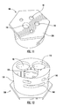
FIG. 11 is a perspective view of a mixing valve for a mixing valve assembly, according to another exemplary embodiment. -
FIG. 12 is another perspective view of the mixing valve shown inFIG. 11 . - Referring to
FIG. 1 , and according to an exemplary embodiment, afaucet assembly 2 includes, among other elements, afaucet spout 3, a spout hub or base 4, a valve assembly, a handle 6, a plurality offluid supply lines mixing valve assembly 8, and a valve assembly (not shown) interfacing or engaging with themixing valve assembly 8. Thefaucet assembly 2 may mount to a sink deck, a countertop, or other mounting surface in any suitable manner. Thefaucet assembly 2 may include two water supply lines, such assupply line 5 and supply line 7 (i.e., one used to carry hot water and one for cold water) that are coupled to amixing valve 1. Thesupply lines FIG. 1 shows a particular type of faucet, it should be understood that other types of faucets may be used with the mixing valve assemblies discussed herein according to other exemplary embodiments. - Further referring to
FIG. 1 , themixing valve 1 may be positioned within the spout hub 4. The twosupply lines valve 1, and may extend downwards toward a mounting surface (not shown) for thefaucet assembly 2. The mixingvalve 1 may be oriented within the spout hub 4 so that aupper surface 23 of the mixingvalve 1 is faced toward a valve assembly (not shown). The valve assembly may be configured so that water supplied from thesupply lines faucet spout 3. A sealing member (not shown) may be disposed between the valve assembly and theupper surface 23 of the mixingvalve 1. Further, in order to prevent water from escaping beyond the valve assembly, the sealing member may be used to sealingly couple the valve assembly and the mixingvalve 1. WhileFIG. 1 shows a particular orientation of the mixingvalve assembly 8 within thefaucet assembly 2, it should be understood that a mixing valve assembly may be arranged in other ways within a faucet assembly. - A mixing valve may be coupled to a valve assembly through various other means. For example, a valve assembly may include a hole used to receive an end proximate the upper surface of a mixing valve. The hole in a valve assembly and an end of a mixing valve may be configured to be coupled according to a particular orientation, thereby ensuring the mixing valve is properly positioned with the valve assembly. For example, the end of a mixing valve may include a protrusion which is configured to engage a recession of the valve assembly, thereby ensuring that the mixing valve and the valve assembly are engaged in a particular orientation.
- According to another exemplary embodiment, a mixing valve assembly may be mounted or positioned in a location spaced away from a faucet spout. For example, a mixing valve assembly may be positioned underneath a sink deck, above a sink deck, or in any other suitable location according to other exemplary embodiments.
- According to an exemplary embodiment, the mixing
valve assembly 8 may be used to control the amount of water that flows from thesupply lines faucet spout 3. For example, the mixingvalve assembly 8 may include a valve, and the position of the valve over theupper surface 23 may control the flow of fluid from thesupply lines faucet spout 3. For example, the valve may be pivoted so that the supply line 5 (supplying, e.g., hot water), is in fluidic communication with an outlet line (see, e.g., thefluid conduit 11 inFIG. 7 ) while the supply line 7 (supplying, e.g., cold water) is not in fluidic communication with an outlet line. A user may control the position of the valve (and therefore, the temperature and flow rate of water flowing through the faucet spout 3) by pivoting the handle 6. - Referring to
FIG. 2 , and according to an exemplary embodiment, the mixingvalve assembly 8 includes the mixingvalve 1, thesupply lines FIG. 2 ), anouter clip 31, and a fluid conduit 11 (not illustrated inFIG. 2 , but shown, for example, inFIG. 7 ). The mixingvalve 1 may include an outlet port (e.g., bore, hole, harbor, etc.), such as anoutlet port 10, which includes a receiving end that is configured to receive thefluid conduit 11. Also, the mixingvalve 1 may include two inlet ports (e.g., bores, holes, harbors, etc.), such asinlet ports inlet ports supply lines first end portion 37 of the mixingvalve 1. Eachinlet port supply lines - Further referring to
FIG. 2 , each of theU-shaped clips 17 may be configured to be received within alateral slot 14, 16 (not shown inFIG. 2 , but shown, for example, inFIG. 4 ) (i.e., an aperture, opening, slit, etc.) disposed within a side wall 15 (not shown inFIG. 2 , but shown, for example, inFIG. 6 ) of the mixingvalve 1. As shown inFIG. 2 , the mixingvalve 1 may include two lateral slots, each of which are openly disposed on opposite sides of the mixing valve. Theouter clip 31 is configured to couple to a portion of theside wall 15 of the mixingvalve 1 and the U-shaped clips 17. For example, theouter clip 31 may be configured to retain theU-shaped clips 17 within the mixingvalve 1 when theouter clip 31 is coupled to the side wall of the mixingvalve 1. - Referring to
FIG. 3 , theinlet ports outlet port 10 may be holes that extend through the mixingvalve 1. Further, theinlet ports upper surface 23 of the mixingvalve 1. As shown inFIG. 3 , theinlet ports valve 1. Also, theoutlet port 10 may be positioned offset from, and between theinlet ports FIG. 3 shows a particular arrangement of inlet and outlet ports of a mixing valve, it should be understood that inlet and outlet ports for a mixing valve may be arranged in other ways, according to other exemplary embodiments. For example, the outlet port for the mixing valve may linearly aligned with a plurality of inlet ports. - In an exemplary embodiment, the mixing
valve 1 may be made from 30% glass-filled nylon. However, it should be understood that other materials may be used to make a mixing valve, such as other polymeric materials, a metal, a composite material, or any other suitable material, according to other exemplary embodiments. - Further, the mixing
valve 1 may include various features or elements used to position the mixing valve relative to the spout hub 4 or a valve assembly. For example, a plurality of positioning members 13 (e.g., protrusions, projections, extensions, locators, etc.) may be disposed on an outer surface of the body portion of the mixingvalve 1. As shown inFIG. 3 , the positioningmember 13 may be configured as a protrusion which is coupled to a generally cylindrical outer surface (i.e., a radial surface) of the mixingvalve 1. The positioningmember 13 may be integrally formed with the mixingvalve 1. An inner surface of the spout hub 4 (which is not shown) may include a plurality of positioning recesses that are each configured to receive either of thepositioning members 13. - In addition to the
positioning members 13 used to position the mixingvalve 1, the mixing valve may include a plurality of positioning holes 25, which are disposed within theupper surface 23. The positioning holes 25 may be configured to be received by a plurality of positioning protrusions of a facing valve assembly (which is not shown), in order to position the valve assembly onto the mixingvalve 1. It should be understood that a mixing valve may include other members and features used to position (e.g., orient, align, etc.) the mixing valve within a faucet assembly, according to other exemplary embodiments. - Referring now to
FIGS. 4-6 , according to an exemplary embodiment, the mixingvalve 1 may include thefirst end portion 37 that is defined by theinlet ports outlet port 10, and an oppositesecond end portion 38 that is defined by theupper surface 23. The mixing valve may be generally cylindrical in the fully assembled state. However, while the figures show various types of mixing valves that may be used in a mixing valve assembly, it should be understood that other types of mixing valves may be used with the mixing valve assemblies discussed herein according to other exemplary embodiments. - Referring to
FIG. 4 , theinlet ports valve 1 may include at least one lateral slot, such as alateral slot 14 and alateral slot 16. An opening for each of thelateral slots side wall 15 of the mixingvalve 1. For a mixing valve that includes more than one lateral slot, such as the mixingvalve 1, thelateral slots valve 1. Alternatively, thelateral slots valve 1. Further, each of thelateral slots inlet port outlet port 10. - Referring to
FIG. 6 , and according to an exemplary embodiment, thelateral slot 14 may be positioned essentially vertically below thelateral slot 16, when the receiving ends of theinlet ports 9, 12 (i.e., the portions near the first end 37) are downwardly oriented. As shown inFIG. 4 , thelateral slot 14 may be openly disposed on a first side of the mixingvalve 1, and thelateral slot 16 may be openly disposed on a second side of the mixingvalve 1, which is opposite the first side. According to another exemplary embodiment, thelateral slot 16 may be openly disposed on the same side of the mixingvalve 1 as thelateral slot 14. - Referring to
FIGS. 4-6 , and according to an exemplary embodiment, the mixingvalve 1 includes aradial groove 36. As shown inFIG. 5 , theradial groove 36 is disposed vertically between the positioningmembers 13 and theupper surface 23. Theradial groove 36 is configured to receive a sealing member, such as an o-ring, (which is not shown) that is configured to sealingly couple an exterior surface of the mixingvalve 1 and another element of the mixingvalve assembly 8, such as the spout hub 4. For example, if water were to leak beyond a sealing member disposed between theupper surface 23 and a valve assembly, then the sealing member received withinradial groove 36 may be used prevent water from leaking beyond theradial groove 36, thereby preventing water from undesirably escaping below the mixingvalve assembly 8 when the assembly is provided in a faucet assembly. - Referring now to
FIG. 5 , the diameter of the opening of theoutlet port 10, which is defined by theupper surface 23 of the mixingvalve 1, may be larger than either of the diameters of the openings of theinlet ports upper surface 23. Referring toFIGS. 4 and 5 , the diameters of the openings of theinlet ports upper surface 23 may be smaller than the openings defined by the receiving ends of theinlet ports inlet ports upper surface 23 may be used to constrain thesupply lines inlet ports supply lines upper surface 23 when theinlet ports supply lines outlet port 10 defined by theupper surface 23 may be smaller than the opening defined by the receiving end of theoutlet port 10. Therefore, theoutlet port 10 may be configured so that thefluid conduit 11 is not able to extend past theupper surface 23 when theoutlet port 10 is received by thefluid conduit 11. - Referring now to
FIG. 6 , a cross-sectional view of the mixingvalve 1 is shown. Theinlet ports valve 1. Theradial groove 36 is shown as being positioned below theprotrusions 13, when theupper surface 23 is downwardly facing. Thelateral slots protrusions 13, when the upper surface is upwardly facing. Further, thelateral slots - Referring now to
FIGS. 7 and 8 , thesupply lines fluid conduit 11 are shown interfacing with the twoU-shaped clips 17 as they would within the mixingvalve 1 when assembled therein. According to an exemplary embodiment, thesupply lines fluid conduit 11 are configured to be coupled to the U-shaped clips when thesupply lines inlet ports outlet port 10. However, in order to clearly show the relationship between theU-shaped clips 17, thesupply lines fluid conduit 11, these elements are shown without the mixingvalve 1. - As shown in
FIGS. 7 and 8 , a coupling, such as acoupling supply lines coupling 34 is coupled to an end of thefluid conduit 11. When thesupply lines inlet ports fluid conduit 11 is received within theoutlet port 10, thecouplings couplings radial grooves 20, and a plurality of secondradial grooves 22. Each secondradial groove 22 may be configured to be received by a sealing member, such as an o-ring. Each firstradial groove 20 ofcouplings arm portions 18 of each of the U-shaped clips 17. In addition, the size of the firstradial groove 20 ofcoupling 34 may be configured to be received by at least onearm portion 18 of each of the U-shaped clips 17. According to an exemplary embodiment, the size of the firstradial grooves 20 and the secondradial grooves 22 may be equal. According to other exemplary embodiments, the size of the first radial grooves may be smaller or larger than the second radial grooves. As shown inFIG. 7 , each of a firstradial groove 20 for thecouplings U-shaped clip 17 from two opposite sides of the mixingvalve 1. According to another embodiment, each of the firstradial grooves 20 of thecouplings valve 1. - According to an exemplary embodiment, a single U-shaped clip may be configured to simultaneously couple to each of the
couplings supply lines inlet ports fluid conduit 11 is received within theoutlet port 10. As shown inFIGS. 7-8 , eacharm portion 18 of theU-shaped clip 17 may be configured to be received within theradial groove 20 of thecouplings arm portion 18 of the U-shaped clip may be received within theradial groove 20 of thecoupling 34. Therefore, a singleU-shaped clip 17 may be simultaneously received within a portion of each of thecouplings supply lines fluid conduit 11 are received within the mixingvalve 1. As a result, a single U-shaped clip may be used to retain a plurality ofsupply lines fluid conduit 11 within the mixingvalve 1. Further, theneck portion 19 of eachU-shaped clip 17 may be received within the radial groove of the coupling (eithercoupling 32 or coupling 33) that is first received within the opening 35 (not shown inFIGS. 7-8 , but shown, for example, inFIG. 9 ) of the U-shaped clip. - According to an exemplary embodiment, one
arm portion 18 of one U-shaped clip may be sufficient to retain thefluid conduit 11 within theoutlet port 10. In contrast to thesupply lines fluid conduit 11 is not pressurized, and less surface area between anarm portion 18 and thegroove 20 may be required to retain thefluid conduit 11 within theoutlet port 10. Further, an outer side of onearm portion 18 may be configured to interact with thegroove 20 of thecoupling 34, whereas an inner side of eacharm portion 18 used in the mixingvalve assembly 8 may be configured to interface with thesupply lines - According to an exemplary embodiment, the first
radial grooves 20 of thecouplings lateral slots inlet ports valve 1 are received by thesupply lines outlet port 10 is received by thefluid conduit 11. Therefore, when each of aradial groove 20 of thefluid conduit 11 and thesupply lines lateral slots valve 1, the firstradial groove 20 andlateral slot U-shaped clip 17, thereby retaining thesupply lines fluid conduit 11 within the mixingvalve 1. - According to an exemplary embodiment, the second
radial grooves 22 of thecouplings valve 1 and either of theinlet ports outlet port 10. It is important to note, according to an exemplary embodiment, the second radial grooves 22 (with sealing members received therein) are positioned proximate the sealingsurface 23 when thecouplings valve 1, in order to provide a suitable water seal between thecouplings valve 1. - According to various exemplary embodiments, the
couplings couplings coupling 34, may be coupled to thesupply lines fluid conduit 11, respectively, in a variety of ways. According to an exemplary embodiment, thesupply lines fluid conduit 11 are made from a polymeric material that is braided. According to various exemplary embodiments, a coupling may be made from a variety of materials, such as a brass, a polymeric material, a composite material, or any other suitable material. According to an exemplary embodiment, thecouplings coupling 34 are crimped onto the ends of thesupply lines fluid conduit 11, respectively. According to another embodiment, each of the couplings may be overmolded onto the end of one of the supply lines or the fluid conduit. Other methods, such as spin welding, may be used to couple the couplings to the end of one of the supply lines or the fluid conduit. According to another exemplary embodiment, a stainless steel braided hose may be used as either the supply lines or the fluid conduit for a faucet assembly, and the hose may be threadably coupled to a coupling. A copper line may be used as either of the supply lines or as the fluid conduit for a faucet assembly, and the couplings may be soldered or brazed to the supply lines or the fluid conduit. While the present disclosure has described several types of materials that may be used as supply lines, a fluid conduit, and couplings, it should be understood that other types of materials may be used to make a supply line, a fluid conduit, and a coupling, according to other exemplary embodiments. It should further be understood that other methods may be used to couple a coupling to either of a supply line or a fluid conduit, according to other exemplary embodiments. - Referring now to
FIG. 9 , a U-shaped clip, such as theU-shaped clip 17, may include twoarm portions 18 and aneck portion 19. Anopening 35 may be defined between eacharm portion 18 of theU-shaped clip 17. Theneck portion 19 may be formed between the twoarm portions 18. According to various exemplary embodiments, theU-shaped clip 17 may be made from a polymeric material, a metal, a composite material, or any other suitable material. Further, the U-shaped clip may be configured to withstand the forces of a water supply line under pressure. - As shown in
FIGS. 7 and 8 , and according to an exemplary embodiment, a U-shaped clip may have a substantially rectangular cross-section. As shown inFIG. 9 , and according to another exemplary embodiment, a U-shaped clip may have a generally oval cross-section. WhileFIGS. 7-9 show various types of U-shaped clips, it should be understood that a U-shaped clip used with the mixing valve assemblies discussed herein may have another cross-section according to other exemplary embodiments (i.e., a U-shaped clip having a circular cross-section, H-shaped, I-shaped cross-section, etc.). - According to an exemplary embodiment of this disclosure, a plurality of pins may be used to retain a plurality of supply lines and a fluid conduit within a mixing valve. For example, a lateral hole may be disposed within a side wall of the mixing valve. Further, the lateral hole may be configured to receive a straight pin. Also, each of the ends of the supply lines and the fluid conduit may be coupled to a coupling that includes a radial groove. When the fluid supply lines and the fluid conduit are received within the inlet ports and the outlet port, respectively, of the mixing valve, a portion of each of the radial grooves of the supply lines and the fluid conduit may be configured to be linearly aligned with the lateral hole, so that the lateral hole and the radial grooves may be received by a straight pin in order to retain the supply lines and the fluid conduit within the mixing valve.
- Referring now to
FIG. 10 , an outer clip, such as theouter clip 31, may be used with the mixingvalve assembly 8. As shown inFIG. 10 , theouter clip 31 may be generally shaped like a number "3." For example, theouter clip 31 may include two symmetrical curved portions. As shown inFIG. 2 , each curved portion of theouter clip 31 may be configured to couple to theside wall 15 of the mixingvalve 1, proximate either of the twoinlet ports outer clip 31 may be configured to match the contour of theside wall 15 in order to retain at least oneU-shaped clip 17 within either of thelateral slots - According to an exemplary embodiment, the
outer clip 31 may be made out of an elastically deformable (i.e., flexible, bendable, resilient) material, such as a polymeric material, a metal, or another flexible material. In other words, theouter clip 31 may be configured to be flexibly coupled onto theside wall 15 of the mixingvalve 1. According to other embodiments, theouter clip 31 may not be made out of a flexible material (i.e., a stiff material). WhileFIGS. 2 and10 show a particular outer clip, this disclosure is not intended to limit the possible ways in which an outer clip may be configured, and it should be understood that other outer clips may be used in a mixing valve assembly discussed herein according to other exemplary embodiments. - According to another exemplary embodiment, a mixing valve assembly may not include an outer clip used to retain a U-shaped clip within a mixing valve. For example, a U-shaped clip may be used in a mixing valve assembly to retain a plurality of supply lines and a fluid conduit within a mixing valve, and the mixing valve may be received by a spout hub or another element which effectively retains the U-shaped clip within the mixing valve. According to another exemplary embodiment, other types of members, such as an elastic member, may be configured to be coupled around a side of a mixing valve in order to retain a U-shaped clip within the mixing valve.
- Referring to
FIGS. 11-12 , according to another embodiment, the mixingvalve 1 may include a body portion that is essentially cylindrical and includes an outer surface 150. The mixingvalve 100 may include a head portion that is defined on one side by aupper surface 230. The perimeter of the head portion and theupper surface 230 may be polygonal in shape (i.e. rectangular, pentagonal, hexagonal, etc.). The head portion may be configured to position the mixing valve within a faucet assembly in a particular orientation. Further, theupper surface 230 may include a plurality of positioning holes, which may be used to position the mixingvalve 100 relative to a valve assembly, or a spout hub. As shown inFIGS. 11-12 , the mixingvalve 100 includes twoinlet ports outlet port 110. The mixingvalve 100 also includes twolateral slots valve 100 in opposite directions. - According to an exemplary embodiment, the mixing
valve 1 may be easily disassembled by performing the following steps. First, the supply valves for thesupply lines valve assembly 8. Next, the mixing valve assembly may be lifted from a spout hub or a spout body. Theouter clip 31 may be detached from theside wall 15 of the mixingvalve 1, if the outer clip is provided with the mixingvalve assembly 8. Next, anyU-shaped clips 17 may be pulled from thelateral slots supply lines fluid conduit 11 may be removed from theinlet ports outlet port 10, respectively. - Advantageously, a plurality of fluid supply lines and a fluid conduit may be retained by a single U-shaped clip within a mixing valve assembly. One skilled in the art will readily appreciate that, for a mixing valve assembly provided in the various embodiments of this disclosure, there may be some limited freedom of movement, including rotational movement, of a supply line or a conduit that is retained within a mixing valve. As a result, it may be easier for a person to assemble a mixing valve assembly within a faucet assembly. A faucet assembly having a fluid supply line and fluid conduit with greater flexibility and freedom of movement may also be easier to install on a mounting surface, such as a sink or a countertop. In addition, a person skilled in the art will appreciate that inexpensive materials, such as polymeric materials, may be used to manufacture a mixing valve assembly provided in the various embodiments of this disclosure.
- As utilized herein, the terms "approximately," "about," "substantially," "essentially," and similar terms are intended to have a broad meaning in harmony with the common and accepted usage by those of ordinary skill in the art to which the subject matter of this disclosure pertains. It should be understood by those of skill in the art who review this disclosure that these terms are intended to allow a description of certain features described and claimed without restricting the scope of these features to the precise numerical ranges provided. Accordingly, these terms should be interpreted as indicating that insubstantial or inconsequential modifications or alterations of the subject matter described and claimed are considered to be within the scope of the disclosure as recited in the appended claims.
- It should be noted that the term "exemplary" as used herein to describe various embodiments is intended to indicate that such embodiments are possible examples, representations, and/or illustrations of possible embodiments (and such term is not intended to connote that such embodiments are necessarily extraordinary or superlative examples).
- The terms "coupled," "connected," and the like as used herein mean the joining oftwo members directly or indirectly to one another. Such joining may be stationary (e.g., permanent) or moveable (e.g., removable or releasable). Such joining may be achieved with the two members or the two members and any additional intermediate members being integrally formed as a single unitary body with one another or with the two members or the two members and any additional intermediate members being attached to one another.
- References herein to the positions of elements (e.g., "top," "bottom," "above," "below," etc.) are merely used to describe the orientation of various elements in the FIGURES. It should be noted that the orientation of various elements may differ according to other exemplary embodiments, and that such variations are intended to be encompassed by the present disclosure.
- It is important to note that the construction and arrangement of the mixing valve assembly as shown in the various exemplary embodiments is illustrative only. Although only a few embodiments have been described in detail in this disclosure, those skilled in the art who review this disclosure will readily appreciate that many modifications are possible (e.g., variations in sizes, dimensions, structures, shapes and proportions of the various elements, values of parameters, mounting arrangements, use of materials, colors, orientations, manufacturing processes, etc.) without materially departing from the novel teachings and advantages of the subject matter described herein. For example, elements shown as integrally formed may be constructed of multiple parts or elements, the position of elements may be reversed or otherwise varied, and the nature or number of discrete elements or positions may be altered or varied. The order or sequence of any process or method steps may be varied or re-sequenced according to alternative embodiments. Other substitutions, modifications, changes and omissions may also be made in the design, operating conditions and arrangement of the various exemplary embodiments without departing from the scope of the present disclosure.
Claims (15)
- A mixing valve (1) for a faucet (2), comprising:a body configured to receive therein end portions of a first fluid supply line (5) and a fluid outlet line (11); anda coupler (17);wherein the coupler (17) is configured for insertion through a sidewall (15) of the body to engage features of the fluid supply line (5) and the fluid outlet line (11) so as to retain the fluid supply line (5) and the fluid outlet line (11) within the body.
- The mixing valve (1) as recited in Claim 1, wherein the first fluid supply line (5) and the fluid outlet line (11) include end portions having grooves (20) formed in exterior surfaces thereof, and the end portions are configured for engaging with the coupler (17) when the coupler (17) is inserted through the sidewall (15) of the body.
- The mixing valve (1) as recited in any one of Claims 1 or 2, wherein the body is also configured to receive a second fluid supply line (7), and wherein the coupler (17) is configured to retain the first and second fluid supply lines (5, 7) and the fluid outlet line (11) within the body.
- The mixing valve (1) as recited in any one of Claims 1 or 2, wherein the body is also configured to receive a second fluid supply line (7), and wherein the ends of the fluid supply lines (5, 7) each comprise a coupling member (32, 33) coupled to a hose, and the features configured to be engaged by the coupler (17) are integrally formed as part of the coupling members (32, 33).
- The mixing valve (1) as recited in Claim 4, wherein the coupling members (32, 33) include a groove, and the grooves are configured to receive a sealing member.
- The mixing valve (1) as recited in any one of Claims 3-5, wherein the body comprises a first and second port (9, 12) for receiving, respectively, the first and second fluid supply lines (5, 7), and a third port (10) for receiving the fluid outlet line (11).
- The mixing valve (1) as recited in any one of Claims 3-6, wherein the mixing valve (1) comprises at least two couplers (17), wherein each of the couplers (17) are configured for insertion through the sidewall (15) of the body at different locations, wherein each of the couplers (17) engage all three of the ends of the first and second fluid supply lines (5, 7) and the fluid outlet line (11) to retain the ends of the first and second fluid supply lines (7) and the fluid outlet line (11) within the body.
- The mixing valve (1) as recited in any of the preceding claims, wherein the first fluid supply line (5) and the fluid outlet line (11) include end portions having a surface configured to abut against an end of the coupler (17) when the coupler (17) is inserted through the sidewall (15) of the body.
- The mixing valve (1) as recited in Claim 8, wherein a coupling member (32) is coupled to the end portion of the first fluid supply line (5), and the surface configured to abut against an end of the coupler (17) is integrally formed on the coupling member (32).
- The mixing valve (1) as recited in any of the preceding claims, wherein the coupler (17) has a generally U-shaped configuration and two ends (18) of the U-shaped coupler (17) are configured for receipt within apertures (14) formed in the body.
- The mixing valve (1) as recited in any of the preceding claims, further comprising a clip (31) that is coupled to an exterior surface of the mixing valve (1) to retain the coupler (17) within the body.
- The mixing valve (1) as recited in any of the preceding claims, wherein the body and the coupler (17) are formed from a polymeric material.
- The mixing valve (1) as recited in any of the preceding claims, wherein the body is formed from a metal.
- A faucet (2) having a mixing valve (1) as recited in any one of Claims 1-13.
- A method for assembling a mixing valve (1) for a faucet (2) as recited in any one of Claims 1-14, comprising:receiving end portions of the fluid supply line (5) and the fluid outline line (11) within the body of the mixing valve (1);inserting a coupler (17) through a sidewall (15) of the body to engage features of the fluid supply line (5) and the fluid outlet line (11) so as to retain the fluid supply line (5) and the fluid outlet line (11) within the body.
Applications Claiming Priority (1)
| Application Number | Priority Date | Filing Date | Title |
|---|---|---|---|
| US201361793560P | 2013-03-15 | 2013-03-15 |
Publications (1)
| Publication Number | Publication Date |
|---|---|
| EP2778300A1 true EP2778300A1 (en) | 2014-09-17 |
Family
ID=50287944
Family Applications (1)
| Application Number | Title | Priority Date | Filing Date |
|---|---|---|---|
| EP20140160130 Withdrawn EP2778300A1 (en) | 2013-03-15 | 2014-03-14 | Mixing valve assembly for faucet |
Country Status (3)
| Country | Link |
|---|---|
| US (1) | US9334634B2 (en) |
| EP (1) | EP2778300A1 (en) |
| CN (1) | CN104048066B (en) |
Cited By (5)
| Publication number | Priority date | Publication date | Assignee | Title |
|---|---|---|---|---|
| CN105908807A (en) * | 2015-02-25 | 2016-08-31 | 高仪股份公司 | plumbing fitting having a hose connection fastened with a clamp |
| EP3418668A1 (en) * | 2017-06-07 | 2018-12-26 | Eberspächer Climate Control Systems GmbH & Co. KG. | Heat exchanger assembly |
| EP3591127A1 (en) * | 2018-07-04 | 2020-01-08 | Villeroy & Boch Gustavsberg AB | A fluid distribution assembly for a faucet and a faucet |
| WO2020143943A1 (en) * | 2019-01-11 | 2020-07-16 | Grohe Ag | Sanitary fitting having a hose securing means |
| EP4058638B1 (en) * | 2019-11-29 | 2023-05-31 | Neoperl GmbH | Sanitary fitting |
Families Citing this family (16)
| Publication number | Priority date | Publication date | Assignee | Title |
|---|---|---|---|---|
| EP3204680B1 (en) | 2014-10-09 | 2023-07-26 | Colder Products Company | Female coupling device |
| WO2017100672A1 (en) * | 2015-12-10 | 2017-06-15 | Saint-Gobain Performance Plastics Corporation | Fluid transport coupling |
| CN107061773B (en) | 2016-01-26 | 2019-05-14 | 科勒公司 | Faucet assembly |
| CN107013698B (en) | 2016-01-26 | 2022-04-12 | 科勒公司 | Valve assembly |
| US10124101B2 (en) * | 2016-07-27 | 2018-11-13 | Tc1 Llc | Fluid resistant locking electrical connector for ventricular assist devices |
| DE102016219218A1 (en) * | 2016-10-04 | 2018-04-05 | Hansgrohe Se | Fixture column and freestanding sanitary fitting system |
| GB2568249B (en) * | 2017-11-08 | 2022-07-06 | Kohler Mira Ltd | Cartridge retention and removal means |
| US11035485B2 (en) * | 2019-04-12 | 2021-06-15 | Hsue Sam Enterprise Co., Ltd. | Faucet structure |
| KR102305473B1 (en) * | 2019-05-02 | 2021-10-01 | 주식회사 아이비코리아 | Drain trap assembly |
| EP4425022A3 (en) | 2019-09-12 | 2025-03-12 | A. Raymond Et Cie | Flow control valve and system for cleaning a vehicle surface |
| US12473719B2 (en) * | 2021-04-08 | 2025-11-18 | Chunhe Qiu | Fluid channel structure and tap |
| US12455016B2 (en) * | 2022-07-13 | 2025-10-28 | As America, Inc. | Rough-in valve |
| DE102022123992A1 (en) * | 2022-09-19 | 2024-03-21 | Neoperl Gmbh | Valve cartridge |
| DE202023100891U1 (en) * | 2023-02-24 | 2024-02-27 | Neoperl Gmbh | Fastening device for fastening hoses to a sanitary fitting |
| US20250327282A1 (en) * | 2024-04-23 | 2025-10-23 | Clement Inc. | Quick installation structure for a body core with rotatable flexible pipe |
| US20250382781A1 (en) * | 2024-06-12 | 2025-12-18 | Clement Inc. | A double-sealed faucet with a rotatable water outlet hose |
Citations (5)
| Publication number | Priority date | Publication date | Assignee | Title |
|---|---|---|---|---|
| US3973791A (en) * | 1974-10-09 | 1976-08-10 | Hps Company, Inc. | Safety coupling device |
| WO1999026010A1 (en) * | 1997-11-19 | 1999-05-27 | Dayco Products, Inc. | Fluid coupling assembly, locking member therefor and method of assembly |
| EP1457727A2 (en) * | 2003-03-11 | 2004-09-15 | Hansgrohe AG | Connection of a sanitary fitting with a conduit |
| US20050138725A1 (en) * | 2003-12-31 | 2005-06-30 | Hydrotek Corporation | Faucet with a connecting structure with a cold and a hot water pipe |
| US20090189108A1 (en) * | 2008-01-28 | 2009-07-30 | Ritter David H | Valve assembly |
Family Cites Families (21)
| Publication number | Priority date | Publication date | Assignee | Title |
|---|---|---|---|---|
| US4423752A (en) * | 1980-12-22 | 1984-01-03 | J. P. Industries, Inc. | Anti-scald mixing valve |
| US4561682A (en) | 1982-09-03 | 1985-12-31 | Rain Bird Consumer Products Mfg. Corp. | Quick connect coupling |
| US4558842A (en) * | 1983-09-06 | 1985-12-17 | Bowen Tools, Inc. | Connector for joining blowout preventer members |
| US5169178A (en) * | 1990-06-14 | 1992-12-08 | Modine Manufacturing Co. | Fitting for use in a heat exchange system |
| IT220672Z2 (en) * | 1990-11-13 | 1993-10-11 | Itw Fastex Italia Spa | SNAP-IN, FLUID-RESISTANT CONNECTION DEVICE, FOR PIPES |
| US5271646A (en) * | 1992-05-04 | 1993-12-21 | Aeroquip Corporation | Coupling assembly |
| FR2691512B1 (en) * | 1992-05-21 | 1995-11-24 | Hutchinson | DEVICE FOR QUICK CONNECTION, BY LATCHING, OF A SET OF TUBULAR ORGANS TO MOUTHPIECES. |
| FR2694797B1 (en) * | 1992-08-12 | 1994-11-04 | Hutchinson | Plate and end-piece for connection device, connection device and its production method. |
| US6073972A (en) * | 1998-05-19 | 2000-06-13 | Emhart Inc. | Composite body faucet connection |
| US6138296A (en) | 1999-06-23 | 2000-10-31 | Emhart Inc. | Easy connect and disconnect faucet spout assembly |
| US6684906B2 (en) | 2001-09-28 | 2004-02-03 | Moen Incorporated | Quick connect/disconnect water faucet conduit assembly |
| CA2469182C (en) | 2001-12-04 | 2014-06-03 | Arichell Technologies, Inc. | Electronic faucets for long-term operation |
| US6609732B1 (en) * | 2002-02-01 | 2003-08-26 | General Motors Corporation | Quick connect multi-hose connector |
| US6738996B1 (en) | 2002-11-08 | 2004-05-25 | Moen Incorporated | Pullout spray head with pause button |
| DK200300082U4 (en) | 2003-03-12 | 2004-06-25 | Damixa As | Mixing battery with swivel spout |
| US20090256348A1 (en) | 2008-04-10 | 2009-10-15 | Bors Mark S | Multi-attachment fitting |
| CA2859105C (en) | 2008-05-21 | 2018-11-27 | Masco Corporation Of Indiana | Integrated kitchen faucet side spray and diverter |
| US8689818B2 (en) | 2008-06-25 | 2014-04-08 | Masco Corporation Of Indiana | Widespread faucet |
| GB201006898D0 (en) * | 2010-04-26 | 2010-06-09 | Kohler Mira Ltd | Fluid connectors |
| US8739813B2 (en) * | 2010-07-21 | 2014-06-03 | Masco Corporation Of Indiana | Waterway for a single supply faucet |
| US8584697B2 (en) * | 2012-02-02 | 2013-11-19 | Da Yuan Sheng Industrial Co. Ltd. | Faucet structure |
-
2014
- 2014-03-12 US US14/206,601 patent/US9334634B2/en active Active
- 2014-03-14 EP EP20140160130 patent/EP2778300A1/en not_active Withdrawn
- 2014-03-14 CN CN201410096567.3A patent/CN104048066B/en not_active Expired - Fee Related
Patent Citations (5)
| Publication number | Priority date | Publication date | Assignee | Title |
|---|---|---|---|---|
| US3973791A (en) * | 1974-10-09 | 1976-08-10 | Hps Company, Inc. | Safety coupling device |
| WO1999026010A1 (en) * | 1997-11-19 | 1999-05-27 | Dayco Products, Inc. | Fluid coupling assembly, locking member therefor and method of assembly |
| EP1457727A2 (en) * | 2003-03-11 | 2004-09-15 | Hansgrohe AG | Connection of a sanitary fitting with a conduit |
| US20050138725A1 (en) * | 2003-12-31 | 2005-06-30 | Hydrotek Corporation | Faucet with a connecting structure with a cold and a hot water pipe |
| US20090189108A1 (en) * | 2008-01-28 | 2009-07-30 | Ritter David H | Valve assembly |
Cited By (8)
| Publication number | Priority date | Publication date | Assignee | Title |
|---|---|---|---|---|
| CN105908807A (en) * | 2015-02-25 | 2016-08-31 | 高仪股份公司 | plumbing fitting having a hose connection fastened with a clamp |
| EP3061877A1 (en) * | 2015-02-25 | 2016-08-31 | Grohe AG | Sanitary fitting with a hose connection fixed with a clamp |
| CN105908807B (en) * | 2015-02-25 | 2020-06-23 | 高仪股份公司 | Sanitary fittings with hose connections secured by clips |
| EP3418668A1 (en) * | 2017-06-07 | 2018-12-26 | Eberspächer Climate Control Systems GmbH & Co. KG. | Heat exchanger assembly |
| US10488119B2 (en) | 2017-06-07 | 2019-11-26 | Eberspächer Climate Control Systems GmbH & Co. KG | Heat exchanger unit |
| EP3591127A1 (en) * | 2018-07-04 | 2020-01-08 | Villeroy & Boch Gustavsberg AB | A fluid distribution assembly for a faucet and a faucet |
| WO2020143943A1 (en) * | 2019-01-11 | 2020-07-16 | Grohe Ag | Sanitary fitting having a hose securing means |
| EP4058638B1 (en) * | 2019-11-29 | 2023-05-31 | Neoperl GmbH | Sanitary fitting |
Also Published As
| Publication number | Publication date |
|---|---|
| US9334634B2 (en) | 2016-05-10 |
| US20140261747A1 (en) | 2014-09-18 |
| CN104048066A (en) | 2014-09-17 |
| CN104048066B (en) | 2016-11-23 |
Similar Documents
| Publication | Publication Date | Title |
|---|---|---|
| US9334634B2 (en) | Mixing valve assembly for faucet | |
| US9151025B2 (en) | Fluid delivery assembly (2-in and 1-out, plus quick-connect diverter housing assembly) | |
| US8800962B2 (en) | Valve assembly having improved connections | |
| US7533683B2 (en) | Cartridge underbody attachment | |
| CN102076599B (en) | Centerset faucet with mountable spout | |
| US5924451A (en) | Structure for faucet | |
| CN111788422B (en) | Method of manufacturing faucet body | |
| US10041233B2 (en) | Faucet valve housing assembly | |
| US12157992B2 (en) | Universal rough-in valve and manifold | |
| CA2652608C (en) | Bridge faucet | |
| CN106917882B (en) | Faucet with offset valve | |
| US12540460B2 (en) | Faucet and pipeline structure thereof | |
| CN107012921B (en) | Sanitary tap with water-guiding hose | |
| CN106894473B (en) | Sanitary water outlet fitting | |
| CA2802804C (en) | Fluid delivery assembly (2-in and 1-out, plus quick-connect diverter housing assembly) | |
| CN221170871U (en) | Tap and pipeline structure thereof | |
| CN117307759B (en) | Faucet device | |
| CN213629020U (en) | A faucet that is easy to disassemble | |
| KR200213458Y1 (en) | Valve structure | |
| JP2006089985A (en) | Branch faucet for hot and cold water mixing plug | |
| RU4147U1 (en) | DEVICE FOR REGULATING WATER CONSUMPTION AND ITS TEMPERATURE | |
| CA2802806C (en) | Fluid delivery system with a housing and at least one fluid inlet and one fluid outlet | |
| KR20100011548U (en) | Faucet assembly with improved assembly | |
| KR20000007248U (en) | Non-return valve |
Legal Events
| Date | Code | Title | Description |
|---|---|---|---|
| 17P | Request for examination filed |
Effective date: 20140314 |
|
| AK | Designated contracting states |
Kind code of ref document: A1 Designated state(s): AL AT BE BG CH CY CZ DE DK EE ES FI FR GB GR HR HU IE IS IT LI LT LU LV MC MK MT NL NO PL PT RO RS SE SI SK SM TR |
|
| AX | Request for extension of the european patent |
Extension state: BA ME |
|
| PUAI | Public reference made under article 153(3) epc to a published international application that has entered the european phase |
Free format text: ORIGINAL CODE: 0009012 |
|
| R17P | Request for examination filed (corrected) |
Effective date: 20150316 |
|
| RBV | Designated contracting states (corrected) |
Designated state(s): AL AT BE BG CH CY CZ DE DK EE ES FI FR GB GR HR HU IE IS IT LI LT LU LV MC MK MT NL NO PL PT RO RS SE SI SK SM TR |
|
| STAA | Information on the status of an ep patent application or granted ep patent |
Free format text: STATUS: EXAMINATION IS IN PROGRESS |
|
| 17Q | First examination report despatched |
Effective date: 20180821 |
|
| RIC1 | Information provided on ipc code assigned before grant |
Ipc: F16L 37/14 20060101ALI20190716BHEP Ipc: E03C 1/04 20060101AFI20190716BHEP Ipc: F16L 37/00 20060101ALI20190716BHEP Ipc: F16K 11/00 20060101ALI20190716BHEP |
|
| GRAP | Despatch of communication of intention to grant a patent |
Free format text: ORIGINAL CODE: EPIDOSNIGR1 |
|
| STAA | Information on the status of an ep patent application or granted ep patent |
Free format text: STATUS: GRANT OF PATENT IS INTENDED |
|
| INTG | Intention to grant announced |
Effective date: 20190918 |
|
| STAA | Information on the status of an ep patent application or granted ep patent |
Free format text: STATUS: THE APPLICATION IS DEEMED TO BE WITHDRAWN |
|
| 18D | Application deemed to be withdrawn |
Effective date: 20200129 |