EP2778050A1 - Active vibration isolation system - Google Patents
Active vibration isolation system Download PDFInfo
- Publication number
- EP2778050A1 EP2778050A1 EP20140153504 EP14153504A EP2778050A1 EP 2778050 A1 EP2778050 A1 EP 2778050A1 EP 20140153504 EP20140153504 EP 20140153504 EP 14153504 A EP14153504 A EP 14153504A EP 2778050 A1 EP2778050 A1 EP 2778050A1
- Authority
- EP
- European Patent Office
- Prior art keywords
- fluid
- vibration
- dual
- hydraulic
- piston assembly
- Prior art date
- Legal status (The legal status is an assumption and is not a legal conclusion. Google has not performed a legal analysis and makes no representation as to the accuracy of the status listed.)
- Granted
Links
Images




Classifications
-
- F—MECHANICAL ENGINEERING; LIGHTING; HEATING; WEAPONS; BLASTING
- F16—ENGINEERING ELEMENTS AND UNITS; GENERAL MEASURES FOR PRODUCING AND MAINTAINING EFFECTIVE FUNCTIONING OF MACHINES OR INSTALLATIONS; THERMAL INSULATION IN GENERAL
- F16F—SPRINGS; SHOCK-ABSORBERS; MEANS FOR DAMPING VIBRATION
- F16F15/00—Suppression of vibrations in systems; Means or arrangements for avoiding or reducing out-of-balance forces, e.g. due to motion
- F16F15/02—Suppression of vibrations of non-rotating, e.g. reciprocating systems; Suppression of vibrations of rotating systems by use of members not moving with the rotating systems
- F16F15/023—Suppression of vibrations of non-rotating, e.g. reciprocating systems; Suppression of vibrations of rotating systems by use of members not moving with the rotating systems using fluid means
- F16F15/027—Suppression of vibrations of non-rotating, e.g. reciprocating systems; Suppression of vibrations of rotating systems by use of members not moving with the rotating systems using fluid means comprising control arrangements
- F16F15/0275—Control of stiffness
-
- B—PERFORMING OPERATIONS; TRANSPORTING
- B64—AIRCRAFT; AVIATION; COSMONAUTICS
- B64C—AEROPLANES; HELICOPTERS
- B64C27/00—Rotorcraft; Rotors peculiar thereto
- B64C27/001—Vibration damping devices
-
- F—MECHANICAL ENGINEERING; LIGHTING; HEATING; WEAPONS; BLASTING
- F16—ENGINEERING ELEMENTS AND UNITS; GENERAL MEASURES FOR PRODUCING AND MAINTAINING EFFECTIVE FUNCTIONING OF MACHINES OR INSTALLATIONS; THERMAL INSULATION IN GENERAL
- F16F—SPRINGS; SHOCK-ABSORBERS; MEANS FOR DAMPING VIBRATION
- F16F15/00—Suppression of vibrations in systems; Means or arrangements for avoiding or reducing out-of-balance forces, e.g. due to motion
- F16F15/02—Suppression of vibrations of non-rotating, e.g. reciprocating systems; Suppression of vibrations of rotating systems by use of members not moving with the rotating systems
- F16F15/023—Suppression of vibrations of non-rotating, e.g. reciprocating systems; Suppression of vibrations of rotating systems by use of members not moving with the rotating systems using fluid means
- F16F15/027—Suppression of vibrations of non-rotating, e.g. reciprocating systems; Suppression of vibrations of rotating systems by use of members not moving with the rotating systems using fluid means comprising control arrangements
-
- F—MECHANICAL ENGINEERING; LIGHTING; HEATING; WEAPONS; BLASTING
- F16—ENGINEERING ELEMENTS AND UNITS; GENERAL MEASURES FOR PRODUCING AND MAINTAINING EFFECTIVE FUNCTIONING OF MACHINES OR INSTALLATIONS; THERMAL INSULATION IN GENERAL
- F16F—SPRINGS; SHOCK-ABSORBERS; MEANS FOR DAMPING VIBRATION
- F16F9/00—Springs, vibration-dampers, shock-absorbers, or similarly-constructed movement-dampers using a fluid or the equivalent as damping medium
- F16F9/32—Details
- F16F9/50—Special means providing automatic damping adjustment, i.e. self-adjustment of damping by particular sliding movements of a valve element, other than flexions or displacement of valve discs; Special means providing self-adjustment of spring characteristics
- F16F9/512—Means responsive to load action, i.e. static load on the damper or dynamic fluid pressure changes in the damper, e.g. due to changes in velocity
- F16F9/5126—Piston, or piston-like valve elements
-
- B—PERFORMING OPERATIONS; TRANSPORTING
- B64—AIRCRAFT; AVIATION; COSMONAUTICS
- B64C—AEROPLANES; HELICOPTERS
- B64C27/00—Rotorcraft; Rotors peculiar thereto
- B64C27/001—Vibration damping devices
- B64C2027/002—Vibration damping devices mounted between the rotor drive and the fuselage
-
- B—PERFORMING OPERATIONS; TRANSPORTING
- B64—AIRCRAFT; AVIATION; COSMONAUTICS
- B64C—AEROPLANES; HELICOPTERS
- B64C27/00—Rotorcraft; Rotors peculiar thereto
- B64C27/001—Vibration damping devices
- B64C2027/004—Vibration damping devices using actuators, e.g. active systems
-
- Y—GENERAL TAGGING OF NEW TECHNOLOGICAL DEVELOPMENTS; GENERAL TAGGING OF CROSS-SECTIONAL TECHNOLOGIES SPANNING OVER SEVERAL SECTIONS OF THE IPC; TECHNICAL SUBJECTS COVERED BY FORMER USPC CROSS-REFERENCE ART COLLECTIONS [XRACs] AND DIGESTS
- Y02—TECHNOLOGIES OR APPLICATIONS FOR MITIGATION OR ADAPTATION AGAINST CLIMATE CHANGE
- Y02T—CLIMATE CHANGE MITIGATION TECHNOLOGIES RELATED TO TRANSPORTATION
- Y02T50/00—Aeronautics or air transport
- Y02T50/40—Weight reduction
Definitions
- the rotor system of an aircraft may act as a source of vibration during operation of the aircraft.
- the aircraft may include a vibration isolation or suppression system to attenuate the vibration as it is transmitted from the rotor system to the airframe. Isolating the vibration as it is transmitted to the airframe may serve to mitigate material fatigue, flight control problems, or other issues that may arise from excessive levels of vibration within the airframe.
- the amount of attenuation or isolation provided by a passive vibration isolation system may be reduced when acted upon by a vibration of a frequency outside of a designed or tuned frequency range of the passive isolation system.
- an apparatus comprising an active vibration isolation system that comprises a vibration isolator, a dual fluid pump in fluid communication with the vibration isolator and a hydraulic system, wherein the dual fluid pump is configured to segregate a tuning fluid from a hydraulic fluid and an electric-hydraulic servo valve in fluid communication with the dual fluid pump.
- an active vibration control system for an aircraft comprising a vibration isolator, a dual fluid pump in fluid communication with both the pylon mount and a hydraulic system of the aircraft, wherein the dual fluid pump is configured to segregate a tuning fluid from a hydraulic fluid and a control computer configured to measure vibration within a fuselage of the rotorcraft and be in signal communication with the vibration isolator and the dual fluid pump.
- a method of isolating vibration comprising isolating vibration transmitted from a gearbox using a vibration isolation system, outputting a control signal to an electric-hydraulic servo valve, communicating a first fluid between the electric-hydraulic servo valve and a dual fluid pump, communicating a feedback signal to the control computer corresponding to the measured displacement of a piston within the pump using a displacement transducer and communicating a second fluid between the vibration isolation system and the dual fluid pump, wherein the first fluid is segregated from the second fluid via the dual fluid pump.
- the AVIS may provide more effective isolation of vibrations across a larger frequency range relative to the isolation provided by passive vibration isolation systems.
- the AVIS may comprise an EHSVAP and a dual fluid pump in fluid communication with a liquid inertia vibration eliminator (LIVETM) and the hydraulic system of the aircraft.
- a control computer of the AVIS may provide feedback to the dual-fluid piston pump via signal outputs from a displacement transducer and one or more vibration sensors coupled to the aircraft.
- the dual-fluid piston pump may be configured to actuate the LIVE using feedback from the control computer.
- system 10 generally comprises a vibratory mass 20, an isolated mass 30, a hydraulic system 40 and an AVIS 100.
- vibratory mass 20 may sinusoidally oscillate or vibrate.
- the isolated mass 30 may comprise a relatively rigid structure, such as a frame or other load bearing structure for supporting a payload.
- the AVIS 100 may be configured to act as a buffer to attenuate or isolate vibratory forces transmitted to the isolated mass 30 of the system 10.
- AVIS 100 generally comprises a vibration isolation system 110, an EHSVAP 130, a control computer 170 and at least one vibration sensor 180.
- EHSVAP generally comprises a servo valve 134 actuated by an electromechanical member 132, a dual fluid pump 140 and a displacement transducer 150.
- vibration isolation system 110 is coupled between the vibratory mass 20 and the isolated mass 30 of the system 10, allowing vibration isolation system 110 to attenuate vibratory forces produced by vibratory mass 20 before they are transmitted to the isolated mass 30.
- vibration isolation system 110 may comprise a vibration isolator, such as a LIVE unit.
- LIVE unit vibration isolators are disclosed in U.S. Patent No. 4,236,607 , which is incorporated in its entirety herein by reference.
- the LIVE unit may comprise a piston coupled to the vibratory mass 20 and disposed within a housing coupled to the isolated mass 30 that is filled with a tuning mass comprising a tuning fluid having a relatively high density and low viscosity.
- the tuning fluid has a density of about 1.6-1.9 grams per centimeters cubed, a kinematic viscosity of about 0.4-0.9 centistokes, a boiling point of about 80-120° Celsius and a pour point of lower than about -40° Celsius.
- a tuning port may extend axially through the piston, providing fluid communication between opposing fluid chambers disposed between the housing and each axial end of the piston Vibratory or oscillatory motion from mass 20 may be transmitted to the piston, causing the tuning fluid disposed within the housing to flow between each fluid chamber via the tuning port.
- the effectiveness of the LIVE unit's ability to isolate vibration may depend on the total mass of the tuning fluid, the cross-sectional area of the tuning port, the cross-sectional area of the piston, the stiffness of the piston motion and other factors. Further, the effectiveness of the LIVE unit in isolating vibration varies with the frequency of vibration of the vibratory mass 20. Thus, a LIVE unit may more effectively isolate vibration within a particular vibration frequency range than vibration at frequencies outside of the range.
- AVIS 100 may allow for active pumping of tuning fluid through the vibration isolation system in response to a signal from a controller, such as control computer 170.
- the vibration isolation provided by system 110 may be continuously adjusted during operation of the system 10.
- vibration isolation system 110 may be adjusted or actuated in response to the frequency and/or amplitude of the vibration transmitted to system 110 by vibratory mass 20.
- system 110 may be adjusted in response to the measured vibration within isolated mass 30, as a result of vibrations being transmitted from isolation system 110 to isolated mass 30.
- EHSVAP 130 is configured to actuate the vibration isolation system 110 in response to signals or data received from a controller, such as control computer 170.
- EHSVAP may be configured to convert the electronic signals from control compute 170 into a hydraulic force for actuating vibration isolation system 110 via the hydraulic power supplied by the hydraulic system 40.
- the electromechanical member 132 of ESHVAP 130 may be configured to convert a received signal from the control computer 170 into a mechanical force for actuating the servo valve 134.
- the servo valve 134 may be in fluid communication with the hydraulic system 40 and the dual fluid pump 140.
- servo valve 134 may comprise a hydraulic spool or servo valve having a plurality of ports and a piston that is translatable in response to actuation from the electromechanical member 132. Translation of the piston may result in fluid flow through one or more of the ports, where each port is in fluid communication with a corresponding port of the dual fluid pump 140.
- the dual fluid pump 140 may be configured to displace tuning fluid of the isolation system 110 in response to actuation from servo valve 134.
- Pump 140 may comprise a piston that is translatable in response to the displacement of hydraulic fluid from hydraulic system 40 via actuation of servo valve 134.
- the piston may displace tuning fluid in response to translation while allowing for the segregation of the tuning fluid and the hydraulic fluid provided by the hydraulic system 140.
- the displacement transducer 150 may be configured to output a piston position signal corresponding to an axial position of the piston.
- displacement transducer 150 may be a linear variable differential transformer (LVDT).
- the actuation of dual fluid pump 140 may actively alter the flow of tuning fluid through the tuning port of the vibration isolation system 110.
- the active actuation of dual fluid pump 140 may produce oscillating or sinusoidal flow of tuning fluid through the isolation system 110, which may isolate or attenuate vibration transmitted from the vibratory mass 20.
- the piston of pump 140 may be axially displaced in an oscillatory manner, resulting in oscillator or sinusoidal flow of tuning fluid through system 110.
- pump 140 may be configured to allow for the adjusting the magnitude of tuning fluid displaced, the sinusoidal frequency of the displaced tuning fluid and the phase angle of the displaced tuning fluid.
- one or more vibration sensors 180 may be configured to measure vibrations within isolated mass 30.
- one or more sensors 180 may be coupled to the isolated mass 30.
- a plurality of sensors 180 may be coupled to isolated mass 30 at various locations of the mass 30.
- Sensors 180 may comprise accelerometers configured to provide a signal output corresponding to the proper acceleration of the sensor 180 in the fore-aft, lateral and vertical directions.
- sensors 180 may comprise other types of sensors capable of measuring vibration of a body or mass, such as velocity sensors, proximity sensors, piezoelectric sensors and the like.
- control computer 170 is configured to receive signals outputted from the displacement transducer 150 and sensors 180 and output a command signal to the electromechanical member 132 for actuating servo valve 134.
- Control computer 170 may comprise a controller algorithm for processing the signal inputs provided by transducer 150 and sensors 180 to form a signal output configured to minimize the magnitude of vibratory force transferred between the vibratory mass 20 and the isolated mass 30.
- computer 170 may comprise a control loop feedback mechanism such as a proportional-integral-derivative (PID) controller algorithm.
- control computer 170 may also comprise one or more amplifiers or other components configured for conditioning the signals outputted by transducer 150 and sensors 180.
- a method 190 may be used for isolating vibration of the vibratory mass 20 from the isolated mass 30 using AVIS 100.
- the method 190 may begin at block 192 by providing a vibration or vibratory force, such as the vibratory force provided by vibratory mass 20.
- the method 190 may continue at block 194 by attenuating or isolating the vibration provided at block 192 using a vibration isolator.
- the vibration may be attenuated using a LIVE system.
- the method 190 may continue at block 196 by measuring the attenuated vibration transmitted to an isolated mass or mass coupled to the vibration isolator, such as isolated mass 30.
- measuring the transmitted violation may be performed using one or more vibration sensors.
- the method 190 may continue at block 198 by providing a command signal using a control computer, such as control computer 170.
- the method 190 may continue at block 200 by actuating a servo valve, such as servo valve 134, in response to the command signal outputted by the control computer.
- actuating the servo valve may comprise actuating the valve using an electromechanical member configured to apply a mechanical force on the servo valve.
- the method 190 may continue at block 202 by actuating a dual fluid pump in response to actuation provided at block 200.
- actuating a dual fluid pump may comprise using hydraulic pressure and energy provided by a hydraulic system.
- the hydraulic system may be a component of the isolated mass, such as isolated mass 30.
- the method 190 continues at block 204 by actuating the vibration isolator described in block 194 in response to the actuation provided at block 202.
- actuating the vibration isolator may comprise displacing a tuning fluid between the vibration isolator and the dual fluid pump.
- the tuning fluid has a density of about 1.6-1.9 grams per centimeters cubed, a kinematic viscosity of about 0.4-0.9 centistokes, a boiling point of about 80-120° Celsius and a pour point of lower than about -40° Celsius.
- the method 190 may continue at block 206 by providing a displacement measurement of a piston of the dual fluid pump to the control computer described at blocks 198 and 200.
- providing a displacement measurement may comprise outputting a signal from a LVDT corresponding to the displacement measurement.
- providing a control signal may comprise processing the measured vibration signal at block 196 and the displacement signal provided at block 206.
- System 300 generally comprises an aircraft or rotorcraft 310 having a fuselage 312, hydraulic system 314 and a drive train 320 comprising an engine 322 coupled to a transmission 324 via a driveshaft 326.
- Drive train 320 further comprises a rotor system 330 that generally includes a mast 332 extending between the transmission 324 and a rotor 334 having a plurality of rotor blades 336 extending therefrom.
- a helicopter is illustrated in FIG. 3 , the described systems and methods could be applied to fixed-wing aircraft, tiltrotor aircraft, or any other type of vehicle or equipment.
- the rotor system 330 of drive train 320 may produce sinusoidal or oscillatory vibratory forces during operation, the frequency range and amplitude of which may depend upon the number of rotor blades, the revolutions per minute (RPM) of the rotor, the speed of the aircraft and other factors.
- the frequency range of vibratory forces generated by the drive train 320 may also depend upon whether the rotorcraft system is a variable rotor speed (RPM) rotorcraft having a rotor with a plurality of operational rotor speeds.
- rotor system 330 of drive train 320 may be of the variable rotor speed type. However, in other embodiments rotor system 330 may only have a single operational rotor speed.
- System 300 further includes an AVIS 340 that is an embodiment of the AVIS 100 disclosed in FIG. 1 .
- AVIS 340 generally comprises a vibration isolator 350, an electro-hydraulic servo valve (EHSV) 370, a dual fluid pump 400, a control computer 420, a plurality of vibration sensors 422 and a displacement transducer 424.
- vibration isolator 350 is coupled to both fuselage 312 and transmission 324 of drive train 320.
- vibrations generated by the operation of the rotor system 330 of rotorcraft 310 may be attenuated by vibration isolator 350 as they are transmitted from rotor system 330 and transmission 324 to the fuselage 312.
- vibration isolator generally comprises a frame 352 that is coupled to the fuselage 312 (shown in FIG. 3 ) and a plurality of LIVE units 354 having a first or upper end 354a and a second or lower end 354b.
- Transmission 324 is coupled to LIVE units 354 at the upper end 354a of each unit 354.
- the lower end 354b of each LIVE unit 354 is coupled to the frame 352.
- vibratory forces applied to transmission 324 from rotor system 330 may be attenuated or isolated via LIVE units 354 prior to being transmitted to frame 352 and fuselage 312.
- LIVE unit 354 generally comprises a piston 356 having a first end 356a and a second end 356b that is disposed within an outer housing 360. Piston 356 also comprises a tuning port 358 extending axially through the piston 356 between first end 356a and second end 356b.
- a first chamber 362a is formed between the first end 356a of piston 356 and housing 360 and a second chamber 362b is formed between the second end 356b and housing 360.
- a tuning fluid 357 is disposed within each chamber 362a, 362b and tuning port 358 of piston 356.
- the tuning fluid has a density of about 1.6-1.9 grams per centimeters cubed, a kinematic viscosity of about 0.4-0.9 centistokes, a boiling point of about 80-120° Celsius and a pour point of lower than about -40° Celsius.
- Tuning fluid may be communicated between chambers 362a, 362b and dual fluid pump 400 via a first port 366a in fluid communication with first chamber 362a and a second port 366b in fluid communication with second chamber 362b.
- each port 366a, 366b is coupled to a corresponding fluid conduit 368a, 368b, respectfully, to provide fluid communication between LIVE unit 354 and dual fluid pump 400.
- EHSV 370 generally comprises an electromechanical member 372 and a servo valve 380.
- member 372 generally comprises an electromagnetic torque motor having a plurality of coil windings 374 in signal communication with the control computer 420. Each winding 374 is disposed about a magnet 376 coupled to an elongate arm 378.
- Member 372 may further comprise an amplifier for conditioning signals communicated by the control computer 420.
- servo valve 380 generally comprises a fluid conduit 382 having a first pair of supply ports 384a, 384b, a second pair of supply ports 386a, 386b, a pair of return ports 388a, 388b and a pair of outlet ports 390a, 390b, all in fluid communication with the hydraulic system 314 of rotorcraft 310 shown in FIG. 3 .
- valve 380 further comprises a piston 392 disposed within conduit 382.
- Piston 392 has a first end 392a, a second end 392b and comprises a first pair of annular seals 394a, 394b, and a second pair of annular seals 396a, 396b.
- Piston 392 also includes an axial throughbore 392c that allows for fluid communication between the pair of supply ports 384a, 384b.
- Elongate arm 378 physically engages piston 392 between seals 394b and 396a, and may axially displace piston 392 within conduit 382 in response to a force applied to the arm 378 from magnet 376 and windings 374.
- supply port 386a may be sealed by annular seal 394a
- return port 388a may be sealed by annular seal 394b
- supply port 386b may be sealed by annular seal 396b
- return port 388b may be sealed by annular seal 396a.
- hydraulic fluid 387 flows from dual fluid pump 400 into valve 380 via a first conduit 398a and outlet port 390a, and returns to the hydraulic system 314 via first return port 388a; and hydraulic fluid flows into valve 380 via second supply port 386b, and flows into dual fluid pump 400 via outlet port 390b and a second fluid conduit 398b.
- hydraulic fluid is supplied to valve 380 by hydraulic system 314 at an approximate range of 1,250-3,000 pounds per square inch (PSI) and is returned to system 314 at an approximate range of 50-150 PSI.
- PSI pounds per square inch
- dual fluid pump 400 is configured to allow for the communication of tuning fluid between LIVE unit 354 and pump 400 and hydraulic fluid between servo valve 380 and pump 400 while maintaining segregation between the tuning fluid and hydraulic fluid.
- Dual fluid pump generally comprises a housing 402 having a piston assembly 404 disposed in a passage 406 therein.
- Piston assembly 404 has a first end 404a, a second end 404b and a flange 405 axially disposed between the first and second ends 404a and 404b.
- three fluid chambers are formed within the housing 402: a first outer chamber 408 disposed between an inner surface of passage 406 and first end 404a of piston assembly 404, a second outer chamber 410 disposed between an inner surface of passage 406 and the second end 404b of piston assembly 404, and a third or inner chamber 412 that is formed between a pair of annular seals 409, disposed radially between the housing 402 and an outer surface of the piston assembly 404. Also, an annular seal 409 is disposed radially between an outer surface of piston assembly 404 and an inner surface of passage 406 near each end 404a, 404b, of piston assembly 404.
- housing 402 of dual fluid pump 400 may further comprise a plurality of ports for providing fluid communication between pump 400 and both LIVE unit 354 and servo valve 380.
- housing 402 further comprises a pair of tuning fluid ports 414a, 414b.
- First tuning port 414a of housing 402 is in fluid communication with first fluid conduit 368a and corresponding first port 366a of LIVE unit 354.
- Second tuning port 414b is in fluid communication with second fluid conduit 368b and second port 366b of LIVE unit 354.
- housing 402 of dual fluid pump 400 may comprise a pair of vent cavities 413a and 413b, with cavity 413a disposed axially between first end 404a and third chamber 412 and cavity 413b disposed axially between third chamber 412 and second end 404b of piston assembly 404.
- Vent cavities 413a and 413b may be configured to allow for the venting to atmosphere of the hydraulic fluid 387 or the tuning fluid 357 in the event that any of the annular seals fail during operation, and thus form a leak path to one of the vent cavities 413a and 413b.
- housing 402 further comprises a pair of hydraulic fluid ports 416a, 416b.
- First hydraulic fluid port 416a is in fluid communication with first conduit 398a and corresponding first outlet port 390a of valve 380.
- Second hydraulic port 416b is in fluid communication with second conduit 398b and corresponding second outlet port 390b of valve 380.
- EHSVAP is configured to adjust the oscillating or sinusoidal flow of tuning fluid through the LIVE unit 354.
- a control signal outputted from the control computer 420 may be received by the electromechanical member 372, which may cause elongate arm 378 to actuate sinusoidally.
- Physical engagement between arm 378 and piston 392 may transmit the sinusoidal movement of arm 378 to piston 392.
- piston 392 is displaced sinusoidally in conduit 382, hydraulic fluid is displaced to and from dual fluid pump 400 in an oscillating pattern.
- hydraulic fluid is displaced from the hydraulic system 314 into the first chamber 408 of dual fluid pump 400 via first fluid conduit 398a, and hydraulic fluid is displaced from the second chamber 410 of pump 400 back into system 314 via second fluid conduit 398b.
- piston 392 has reversed direction, and is displaced in the direction of second end 392b (as shown in FIG. 6 )
- the flow of hydraulic fluid between pump 400 and valve 380 becomes reversed.
- hydraulic fluid is displaced from hydraulic system 314 into the second chamber 410 of pump 400 via second fluid conduit 398b and fluid is displaced from fist chamber 408 into system 314 via first conduit 398a.
- the oscillating flow of hydraulic fluid between servo valve 380 and dual fluid pump 400 results in a corresponding oscillating or sinusoidal movement of piston assembly 404 within passage 406.
- piston 392 of valve 380 is disposed in the arrangement shown in FIG. 6
- the flow of hydraulic fluid into second chamber 410 increases the fluid pressure force acting on second end 404b of piston assembly 404.
- first fluid conduit 398a the fluid pressure force acting on first end 404a of piston assembly 404 is decreased.
- the relative increase of fluid pressure force acting on second end 404b and the relative decrease acting on first end 404a results in axial movement of piston assembly 404 within passage 406 in the direction of first end 404a. Reversing the direction of flow of hydraulic fluid into and out of chambers 408 and 410 may serve to relatively increase the pressure force acting on first end 404a and decrease the pressure force acting on second end 404b, resulting in axial displacement of piston assembly 404 in the opposite axial direction, towards second end 404b.
- the sinusoidal displacement of piston assembly 404 in passage 406 results in an adjustment of the oscillating flow of tuning fluid into and out of chambers 362a, 362b, tuning port 358, of LIVE unit 354 resulting from vibratory forces passing through the unit 354.
- a closed fluid system 418 having an approximately constant or fixed volume is formed by the combination of first and second chambers 362a, 362b, tuning port 358, first and second fluid conduits 368a, 368b, and the third chamber 412 of dual fluid pump 400.
- the relative size of first portion 412a and second portion 412b shift, causing tuning fluid to be displaced within fluid conduits 368a, 368b and tuning port 358.
- first portion 412a is decreased, thus expelling or pumping fluid from first portion 412a through conduit 368a and into first chamber 362a.
- tuning fluid within first chamber 362a is displaced through tuning port 358 toward second chamber 368b.
- Tuning fluid within second chamber 362b may be displaced through conduit 368b toward second portion 412b of chamber 412.
- the flow of tuning fluid within closed system 418 may be reversed by reversing the axial direction of displacement of piston assembly 404 within 406, towards second end 404b.
- the axial position or displacement of piston assembly 404 may be continuously monitored and an output signal corresponding to the axial position of piston assembly 404 may be transmitted via the displacement transducer 424, which may be coupled to the pump 400.
- the signal output of displacement transducer 424 may be used to compute the sinusoidal frequency of piston assembly 404 using control computer 420.
- control computer 420 may be configured to adjust the sinusoidal frequency of piston assembly 404 in response to the frequency of vibrations measured by the one or more vibration sensors 422 coupled to the fuselage 312.
- control computer 420 and EHSV 370 may be configured to adjust the volume of tuning fluid displaced within closed system 418, the sinusoidal frequency of the displaced tuning fluid and the phase angle of the displaced tuning fluid relative to the azimuth position of the rotor 334 of rotor system 330.
- a control algorithm such as a PID controller algorithm may be used to compute an output signal in response to the signals outputted from sensors 422 and displacement transducer 424.
- displacement transducer 424 may comprise an LVDT.
- a dual fluid pump 460 comprises a housing 462 having a central passage 464 and a piston assembly 466 disposed within passage 464.
- Piston assembly 466 has a first end 466a and a second end 466b.
- Piston assembly 466 comprises a first flange 468a disposed at first end 466a and a second flange 468b axially spaced from first flange 468a.
- Piston assembly 466 also comprises a third flange 468c disposed at second end 466b and a fourth flange 468d axially spaced from third flange 468c.
- Each flange 468a-468d has an outer radial surface that sealingly engages an inner surface of passage 464.
- housing 462 includes a flange 470 that extends into passage 464 and sealingly engages an outer surface of piston assembly 466.
- This arrangement forms four fluid chambers: a first fluid chamber 472a disposed between flange 470 of housing 462 and second flange 468b of piston assembly 466, a second fluid chamber 472b disposed between flange 470 and fourth flange 468d of piston assembly 466, a third fluid chamber 472c disposed at first end 466a of piston assembly 466 and a fourth fluid chamber 472d disposed at second end 466b of piston assembly 466.
- Housing 462 further comprises a plurality of ports, with a first pair of inlet ports 474a, 474b, providing fluid communication from the servo valve 380 to first and second fluid chambers 472a, 472b, respectfully, and a pair of outlet ports 476a, 476b, providing fluid communication between third and fourth fluid chambers 472c, 472d, and LIVE unit 354.
- Displacement transducer 424 may measure the position or displacement of piston assembly 466 in passage 464.
- a first dual fluid pump 510 comprises a housing 512 having a central passage 514 and a piston assembly 516a disposed within passage 514.
- Piston assembly 516a has a first end 516a and a second end 516b.
- a first fluid passage 518a provides fluid communication between servo valve 380 and pump 510 and a second fluid passage 518b provides fluid communication between pump 510 and LIVE unit 354.
- second dual fluid pump 520 comprises a housing 522 having a central passage 524 and a piston assembly 526 disposed within passage 524.
- Piston assembly 526 has a first end 526a and a second end 526b.
- a first fluid passage 528a provides fluid communication between servo valve 380 and pump 520 and a second fluid passage 528b provides fluid communication between pump 520 and LIVE unit 354.
- Displacement transducer 424 may measure the linear position or displacement of piston assembly 516 of pump 510 and piston assembly 526 of pump 520.
- a method 500 for isolating vibration in an aircraft may begin at block 502 by providing an AVIS.
- "providing" the AVIS may comprise designing, manufacturing or assembling the AVIS.
- the AVIS may comprise AVIS 300 described in FIGS. 3-8 .
- the method 500 may continue at block 504 by operating an aircraft comprising the AVIS of block 502.
- block 504 may comprise isolating or attenuating vibrations transmitted between a drive train (e.g., drive train 320 shown in Figure 3 ) of an aircraft (e.g., aircraft 310) and the fuselage (e.g., fuselage 312) of the aircraft.
- a drive train e.g., drive train 320 shown in Figure 3
- the fuselage e.g., fuselage 312
- R R l +k*(R u -R l ), wherein k is a variable ranging from 1 percent to 100 percent with a 1 percent increment, i.e., k is 1 percent, 2 percent, 3 percent, 4 percent, 5 percent, ..., 50 percent, 51 percent, 52 percent, ..., 95 percent, 96 percent, 97 percent, 98 percent, 99 percent, or 100 percent. Unless otherwise stated, the term "about” shall mean plus or minus 10 percent. Of the subsequent value.
- any numerical range defined by two R numbers as defined in the above is also specifically disclosed.
- Use of the term “optionally” with respect to any element of a claim means that the element is required, or alternatively, the element is not required, both alternatives being within the scope of the claim.
- Use of broader terms such as comprises, includes, and having should be understood to provide support for narrower terms such as consisting of, consisting essentially of, and comprised substantially of. Accordingly, the scope of protection is not limited by the description set out above but is defined by the claims that follow, that scope including all equivalents of the subject matter of the claims.
- Each and every claim is incorporated as further disclosure into the specification and the claims are embodiment(s) of the present invention.
Landscapes
- Engineering & Computer Science (AREA)
- General Engineering & Computer Science (AREA)
- Mechanical Engineering (AREA)
- Aviation & Aerospace Engineering (AREA)
- Physics & Mathematics (AREA)
- Acoustics & Sound (AREA)
- Fluid Mechanics (AREA)
- Vibration Prevention Devices (AREA)
Abstract
Description
- Not applicable.
- Not applicable.
- Not applicable.
- The rotor system of an aircraft, such as a helicopter or tiltrotor aircraft, may act as a source of vibration during operation of the aircraft. The aircraft may include a vibration isolation or suppression system to attenuate the vibration as it is transmitted from the rotor system to the airframe. Isolating the vibration as it is transmitted to the airframe may serve to mitigate material fatigue, flight control problems, or other issues that may arise from excessive levels of vibration within the airframe. The amount of attenuation or isolation provided by a passive vibration isolation system may be reduced when acted upon by a vibration of a frequency outside of a designed or tuned frequency range of the passive isolation system.
- In some embodiments of the disclosure, an apparatus is disclosed as comprising an active vibration isolation system that comprises a vibration isolator, a dual fluid pump in fluid communication with the vibration isolator and a hydraulic system, wherein the dual fluid pump is configured to segregate a tuning fluid from a hydraulic fluid and an electric-hydraulic servo valve in fluid communication with the dual fluid pump.
- In other embodiments of the disclosure, an active vibration control system for an aircraft is disclosed as comprising a vibration isolator, a dual fluid pump in fluid communication with both the pylon mount and a hydraulic system of the aircraft, wherein the dual fluid pump is configured to segregate a tuning fluid from a hydraulic fluid and a control computer configured to measure vibration within a fuselage of the rotorcraft and be in signal communication with the vibration isolator and the dual fluid pump.
- In still other embodiments of the disclosure, a method of isolating vibration is disclosed as comprising isolating vibration transmitted from a gearbox using a vibration isolation system, outputting a control signal to an electric-hydraulic servo valve, communicating a first fluid between the electric-hydraulic servo valve and a dual fluid pump, communicating a feedback signal to the control computer corresponding to the measured displacement of a piston within the pump using a displacement transducer and communicating a second fluid between the vibration isolation system and the dual fluid pump, wherein the first fluid is segregated from the second fluid via the dual fluid pump.
- For a more complete understanding of the present disclosure and the advantages thereof, reference is now made to the following brief description, taken in connection with the accompanying drawings and detailed description:
-
FIG. 1 is a schematic illustration of an active vibration isolation system (AVIS) according to an embodiment of the disclosure; -
FIG. 2 is a flowchart of a method of actively isolating vibration according to an embodiment of the disclosure; -
FIG. 3 illustrates a system including an AVIS according to an embodiment of the disclosure; -
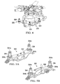
FIG. 4 is an orthogonal view of a transmission and vibration isolator of the system ofFIG. 3 ; -
FIG. 5A is an orthogonal view of a vibration isolator of the system ofFIG. 3 ; -
FIG. 5B is an orthogonal view of a vibration isolator of the system ofFIG. 3 ; -
FIG. 6 is a schematic view of an electro-hydraulic servo valve actuated pumper (EHSVAP) of the system ofFIG. 1 ; -
FIG. 7 is a schematic view of another embodiment of an EHSVAP according to an embodiment of the disclosure; -
FIG. 8 is a schematic view of another embodiment of an EHSVAP according to an embodiment of the disclosure; and -
FIG. 9 is a flowchart of a method isolating vibration in an aircraft according to an embodiment of the disclosure. - It should be understood at the outset that although an illustrative implementation of one or more embodiments are provided below, the disclosed systems and/or methods may be implemented using any number of techniques, whether currently known or in existence. The disclosure should in no way be limited to the illustrative implementations, drawings, and techniques illustrated below, including the exemplary designs and implementations illustrated and described herein, but may be modified within the scope of the appended claims along with their full scope of equivalents.
- In some cases, it may be desirable to provide an AVIS configured to attenuate vibrations generated by the rotor system of an aircraft, such as a helicopter or other rotorcraft. In some embodiments of the disclosure, the AVIS may provide more effective isolation of vibrations across a larger frequency range relative to the isolation provided by passive vibration isolation systems. In some embodiments, the AVIS may comprise an EHSVAP and a dual fluid pump in fluid communication with a liquid inertia vibration eliminator (LIVE™) and the hydraulic system of the aircraft. In some embodiments, a control computer of the AVIS may provide feedback to the dual-fluid piston pump via signal outputs from a displacement transducer and one or more vibration sensors coupled to the aircraft. In some embodiments, the dual-fluid piston pump may be configured to actuate the LIVE using feedback from the control computer.
- Referring now to
FIG. 1 , a block diagram illustrating asystem 10 is shown according to an embodiment of the invention. In this embodiment,system 10 generally comprises avibratory mass 20, anisolated mass 30, ahydraulic system 40 and anAVIS 100. In an embodiment,vibratory mass 20 may sinusoidally oscillate or vibrate. Theisolated mass 30 may comprise a relatively rigid structure, such as a frame or other load bearing structure for supporting a payload. - The
AVIS 100 may be configured to act as a buffer to attenuate or isolate vibratory forces transmitted to theisolated mass 30 of thesystem 10. In an embodiment,AVIS 100 generally comprises avibration isolation system 110, anEHSVAP 130, acontrol computer 170 and at least onevibration sensor 180. In some embodiments, EHSVAP generally comprises aservo valve 134 actuated by anelectromechanical member 132, adual fluid pump 140 and adisplacement transducer 150. In this embodiment,vibration isolation system 110 is coupled between thevibratory mass 20 and theisolated mass 30 of thesystem 10, allowingvibration isolation system 110 to attenuate vibratory forces produced byvibratory mass 20 before they are transmitted to theisolated mass 30. - In an embodiment,
vibration isolation system 110 may comprise a vibration isolator, such as a LIVE unit. LIVE unit vibration isolators are disclosed inU.S. Patent No. 4,236,607 , which is incorporated in its entirety herein by reference. In this embodiment, the LIVE unit may comprise a piston coupled to thevibratory mass 20 and disposed within a housing coupled to theisolated mass 30 that is filled with a tuning mass comprising a tuning fluid having a relatively high density and low viscosity. In an embodiment, the tuning fluid has a density of about 1.6-1.9 grams per centimeters cubed, a kinematic viscosity of about 0.4-0.9 centistokes, a boiling point of about 80-120° Celsius and a pour point of lower than about -40° Celsius. A tuning port may extend axially through the piston, providing fluid communication between opposing fluid chambers disposed between the housing and each axial end of the piston Vibratory or oscillatory motion frommass 20 may be transmitted to the piston, causing the tuning fluid disposed within the housing to flow between each fluid chamber via the tuning port. - The effectiveness of the LIVE unit's ability to isolate vibration (i.e., prevent vibration from being transmitted from
vibratory mass 20 to isolated mass 30) at a given amplitude and frequency may depend on the total mass of the tuning fluid, the cross-sectional area of the tuning port, the cross-sectional area of the piston, the stiffness of the piston motion and other factors. Further, the effectiveness of the LIVE unit in isolating vibration varies with the frequency of vibration of thevibratory mass 20. Thus, a LIVE unit may more effectively isolate vibration within a particular vibration frequency range than vibration at frequencies outside of the range. - One factor in the relationship between the effectiveness of vibratory isolation of the LIVE unit and vibration frequency may relate to the passive nature of the LIVE unit, in that flow of the tuning fluid through the tuning port and oscillation of the piston is driven passively in response to vibration of the
vibratory mass 20. In some embodiments,AVIS 100 may allow for active pumping of tuning fluid through the vibration isolation system in response to a signal from a controller, such ascontrol computer 170. In this manner, the vibration isolation provided bysystem 110 may be continuously adjusted during operation of thesystem 10. For example,vibration isolation system 110 may be adjusted or actuated in response to the frequency and/or amplitude of the vibration transmitted tosystem 110 byvibratory mass 20. Also,system 110 may be adjusted in response to the measured vibration withinisolated mass 30, as a result of vibrations being transmitted fromisolation system 110 toisolated mass 30. - In an embodiment,
EHSVAP 130 is configured to actuate thevibration isolation system 110 in response to signals or data received from a controller, such ascontrol computer 170. In actuating thevibration isolation system 110 in response to signals fromcontrol computer 170, EHSVAP may be configured to convert the electronic signals fromcontrol compute 170 into a hydraulic force for actuatingvibration isolation system 110 via the hydraulic power supplied by thehydraulic system 40. - In an embodiment, the
electromechanical member 132 ofESHVAP 130 may be configured to convert a received signal from thecontrol computer 170 into a mechanical force for actuating theservo valve 134. Theservo valve 134 may be in fluid communication with thehydraulic system 40 and thedual fluid pump 140. In an embodiment,servo valve 134 may comprise a hydraulic spool or servo valve having a plurality of ports and a piston that is translatable in response to actuation from theelectromechanical member 132. Translation of the piston may result in fluid flow through one or more of the ports, where each port is in fluid communication with a corresponding port of thedual fluid pump 140. - In some embodiments, the
dual fluid pump 140 may be configured to displace tuning fluid of theisolation system 110 in response to actuation fromservo valve 134. Pump 140 may comprise a piston that is translatable in response to the displacement of hydraulic fluid fromhydraulic system 40 via actuation ofservo valve 134. The piston may displace tuning fluid in response to translation while allowing for the segregation of the tuning fluid and the hydraulic fluid provided by thehydraulic system 140. In some embodiments, thedisplacement transducer 150 may be configured to output a piston position signal corresponding to an axial position of the piston. In an embodiment,displacement transducer 150 may be a linear variable differential transformer (LVDT). - In some embodiments, the actuation of
dual fluid pump 140 may actively alter the flow of tuning fluid through the tuning port of thevibration isolation system 110. The active actuation ofdual fluid pump 140 may produce oscillating or sinusoidal flow of tuning fluid through theisolation system 110, which may isolate or attenuate vibration transmitted from thevibratory mass 20. For instance, the piston ofpump 140 may be axially displaced in an oscillatory manner, resulting in oscillator or sinusoidal flow of tuning fluid throughsystem 110. In an embodiment, pump 140 may be configured to allow for the adjusting the magnitude of tuning fluid displaced, the sinusoidal frequency of the displaced tuning fluid and the phase angle of the displaced tuning fluid. - In some embodiments, one or
more vibration sensors 180 may be configured to measure vibrations withinisolated mass 30. For example, one ormore sensors 180 may be coupled to theisolated mass 30. In an embodiment, a plurality ofsensors 180 may be coupled toisolated mass 30 at various locations of themass 30.Sensors 180 may comprise accelerometers configured to provide a signal output corresponding to the proper acceleration of thesensor 180 in the fore-aft, lateral and vertical directions. However, inother embodiments sensors 180 may comprise other types of sensors capable of measuring vibration of a body or mass, such as velocity sensors, proximity sensors, piezoelectric sensors and the like. - In some embodiments, the
control computer 170 is configured to receive signals outputted from thedisplacement transducer 150 andsensors 180 and output a command signal to theelectromechanical member 132 for actuatingservo valve 134.Control computer 170 may comprise a controller algorithm for processing the signal inputs provided bytransducer 150 andsensors 180 to form a signal output configured to minimize the magnitude of vibratory force transferred between thevibratory mass 20 and theisolated mass 30. For instance, in an embodiment,computer 170 may comprise a control loop feedback mechanism such as a proportional-integral-derivative (PID) controller algorithm. In some embodiments,control computer 170 may also comprise one or more amplifiers or other components configured for conditioning the signals outputted bytransducer 150 andsensors 180. - Referring now to
FIG. 2 , amethod 190 may be used for isolating vibration of thevibratory mass 20 from theisolated mass 30 usingAVIS 100. Themethod 190 may begin atblock 192 by providing a vibration or vibratory force, such as the vibratory force provided byvibratory mass 20. Themethod 190 may continue atblock 194 by attenuating or isolating the vibration provided atblock 192 using a vibration isolator. In some embodiments, the vibration may be attenuated using a LIVE system. Themethod 190 may continue atblock 196 by measuring the attenuated vibration transmitted to an isolated mass or mass coupled to the vibration isolator, such asisolated mass 30. In some embodiments, measuring the transmitted violation may be performed using one or more vibration sensors. - The
method 190 may continue atblock 198 by providing a command signal using a control computer, such ascontrol computer 170. Themethod 190 may continue atblock 200 by actuating a servo valve, such asservo valve 134, in response to the command signal outputted by the control computer. In some embodiments, actuating the servo valve may comprise actuating the valve using an electromechanical member configured to apply a mechanical force on the servo valve. Themethod 190 may continue atblock 202 by actuating a dual fluid pump in response to actuation provided atblock 200. In some embodiments, actuating a dual fluid pump may comprise using hydraulic pressure and energy provided by a hydraulic system. In an embodiment, the hydraulic system may be a component of the isolated mass, such asisolated mass 30. - The
method 190 continues atblock 204 by actuating the vibration isolator described inblock 194 in response to the actuation provided atblock 202. In some embodiments, actuating the vibration isolator may comprise displacing a tuning fluid between the vibration isolator and the dual fluid pump. In an embodiment, the tuning fluid has a density of about 1.6-1.9 grams per centimeters cubed, a kinematic viscosity of about 0.4-0.9 centistokes, a boiling point of about 80-120° Celsius and a pour point of lower than about -40° Celsius. Themethod 190 may continue atblock 206 by providing a displacement measurement of a piston of the dual fluid pump to the control computer described atblocks block 196 and the displacement signal provided atblock 206. - Referring now to
FIG. 3 , asystem 300 according to an embodiment of the disclosure is shown.System 300 generally comprises an aircraft orrotorcraft 310 having afuselage 312,hydraulic system 314 and adrive train 320 comprising anengine 322 coupled to atransmission 324 via adriveshaft 326. Drivetrain 320 further comprises arotor system 330 that generally includes amast 332 extending between thetransmission 324 and arotor 334 having a plurality ofrotor blades 336 extending therefrom. It will be appreciated that while a helicopter is illustrated inFIG. 3 , the described systems and methods could be applied to fixed-wing aircraft, tiltrotor aircraft, or any other type of vehicle or equipment. - The
rotor system 330 ofdrive train 320 may produce sinusoidal or oscillatory vibratory forces during operation, the frequency range and amplitude of which may depend upon the number of rotor blades, the revolutions per minute (RPM) of the rotor, the speed of the aircraft and other factors. The frequency range of vibratory forces generated by thedrive train 320 may also depend upon whether the rotorcraft system is a variable rotor speed (RPM) rotorcraft having a rotor with a plurality of operational rotor speeds. In an embodiment,rotor system 330 ofdrive train 320 may be of the variable rotor speed type. However, in otherembodiments rotor system 330 may only have a single operational rotor speed. -
System 300 further includes anAVIS 340 that is an embodiment of theAVIS 100 disclosed inFIG. 1 .AVIS 340 generally comprises avibration isolator 350, an electro-hydraulic servo valve (EHSV) 370, adual fluid pump 400, acontrol computer 420, a plurality ofvibration sensors 422 and adisplacement transducer 424. In this embodiment,vibration isolator 350 is coupled to bothfuselage 312 andtransmission 324 ofdrive train 320. In this arrangement, vibrations generated by the operation of therotor system 330 of rotorcraft 310 (e.g., during flight) may be attenuated byvibration isolator 350 as they are transmitted fromrotor system 330 andtransmission 324 to thefuselage 312. - Referring now to
FIGS. 4, 5A and 5B , orthogonal views oftransmission 324 andvibration isolator 350 ofsystem 300 are shown. In this embodiment, vibration isolator generally comprises aframe 352 that is coupled to the fuselage 312 (shown inFIG. 3 ) and a plurality ofLIVE units 354 having a first orupper end 354a and a second orlower end 354b.Transmission 324 is coupled to LIVEunits 354 at theupper end 354a of eachunit 354. Also, thelower end 354b of eachLIVE unit 354 is coupled to theframe 352. In this arrangement, vibratory forces applied totransmission 324 from rotor system 330 (shown inFIG. 3 ) may be attenuated or isolated viaLIVE units 354 prior to being transmitted to frame 352 andfuselage 312. - Referring now to
FIG. 6 , a schematic view of an embodiment ofLIVE unit 354,EHSV 370 anddual fluid pump 400 are shown. In this embodiment,LIVE unit 354 generally comprises apiston 356 having afirst end 356a and asecond end 356b that is disposed within an outer housing 360.Piston 356 also comprises atuning port 358 extending axially through thepiston 356 betweenfirst end 356a andsecond end 356b. Afirst chamber 362a is formed between thefirst end 356a ofpiston 356 and housing 360 and asecond chamber 362b is formed between thesecond end 356b and housing 360. A tuningfluid 357 is disposed within eachchamber port 358 ofpiston 356. In an embodiment, the tuning fluid has a density of about 1.6-1.9 grams per centimeters cubed, a kinematic viscosity of about 0.4-0.9 centistokes, a boiling point of about 80-120° Celsius and a pour point of lower than about -40° Celsius. Tuning fluid may be communicated betweenchambers dual fluid pump 400 via afirst port 366a in fluid communication withfirst chamber 362a and asecond port 366b in fluid communication withsecond chamber 362b. Also, eachport fluid conduit LIVE unit 354 anddual fluid pump 400. - In this embodiment,
EHSV 370 generally comprises anelectromechanical member 372 and aservo valve 380. In some embodiments,member 372 generally comprises an electromagnetic torque motor having a plurality ofcoil windings 374 in signal communication with thecontrol computer 420. Each winding 374 is disposed about amagnet 376 coupled to anelongate arm 378.Member 372 may further comprise an amplifier for conditioning signals communicated by thecontrol computer 420. In this embodiment,servo valve 380 generally comprises afluid conduit 382 having a first pair ofsupply ports supply ports return ports outlet ports hydraulic system 314 ofrotorcraft 310 shown inFIG. 3 . - In this embodiment,
valve 380 further comprises apiston 392 disposed withinconduit 382.Piston 392 has afirst end 392a, asecond end 392b and comprises a first pair ofannular seals annular seals Piston 392 also includes an axial throughbore 392c that allows for fluid communication between the pair ofsupply ports Elongate arm 378 physically engagespiston 392 betweenseals piston 392 withinconduit 382 in response to a force applied to thearm 378 frommagnet 376 andwindings 374. Aspiston 392 is axially displaced withinconduit 382,supply port 386a may be sealed byannular seal 394a, returnport 388a may be sealed byannular seal 394b,supply port 386b may be sealed byannular seal 396b and returnport 388b may be sealed byannular seal 396a. - As shown in
FIG. 6 ,piston 392 has been displaced in the direction ofsecond end 392b. In this configuration, a first route of fluid communication is provided betweenreturn port 388a andoutlet port 390a and a second route of fluid communication is provided betweenoutlet port 390b andsecond supply port 386b. In this arrangement,hydraulic fluid 387 flows fromdual fluid pump 400 intovalve 380 via afirst conduit 398a andoutlet port 390a, and returns to thehydraulic system 314 viafirst return port 388a; and hydraulic fluid flows intovalve 380 viasecond supply port 386b, and flows intodual fluid pump 400 viaoutlet port 390b and a secondfluid conduit 398b. In an embodiment, hydraulic fluid is supplied tovalve 380 byhydraulic system 314 at an approximate range of 1,250-3,000 pounds per square inch (PSI) and is returned tosystem 314 at an approximate range of 50-150 PSI. - In some embodiments,
dual fluid pump 400 is configured to allow for the communication of tuning fluid betweenLIVE unit 354 and pump 400 and hydraulic fluid betweenservo valve 380 and pump 400 while maintaining segregation between the tuning fluid and hydraulic fluid. Dual fluid pump generally comprises a housing 402 having apiston assembly 404 disposed in a passage 406 therein.Piston assembly 404 has afirst end 404a, asecond end 404b and aflange 405 axially disposed between the first andsecond ends outer chamber 408 disposed between an inner surface of passage 406 andfirst end 404a ofpiston assembly 404, a secondouter chamber 410 disposed between an inner surface of passage 406 and thesecond end 404b ofpiston assembly 404, and a third orinner chamber 412 that is formed between a pair ofannular seals 409, disposed radially between the housing 402 and an outer surface of thepiston assembly 404. Also, anannular seal 409 is disposed radially between an outer surface ofpiston assembly 404 and an inner surface of passage 406 near eachend piston assembly 404. - In this embodiment, an
annular seal 411 is created between an outer radial surface 405a offlange 405 and the inner surface of the passage 406 of housing 402.Seal 411 may dividethird chamber 412 into afirst portion 412a and asecond portion 412b. Housing 402 ofdual fluid pump 400 may further comprise a plurality of ports for providing fluid communication betweenpump 400 and both LIVEunit 354 andservo valve 380. In this embodiment, housing 402 further comprises a pair of tuningfluid ports First tuning port 414a of housing 402 is in fluid communication with firstfluid conduit 368a and correspondingfirst port 366a ofLIVE unit 354.Second tuning port 414b is in fluid communication with secondfluid conduit 368b andsecond port 366b ofLIVE unit 354. - In this embodiment, housing 402 of
dual fluid pump 400 may comprise a pair ofvent cavities cavity 413a disposed axially betweenfirst end 404a andthird chamber 412 andcavity 413b disposed axially betweenthird chamber 412 andsecond end 404b ofpiston assembly 404.Vent cavities hydraulic fluid 387 or the tuning fluid 357 in the event that any of the annular seals fail during operation, and thus form a leak path to one of thevent cavities - In this embodiment, housing 402 further comprises a pair of
hydraulic fluid ports hydraulic fluid port 416a is in fluid communication withfirst conduit 398a and correspondingfirst outlet port 390a ofvalve 380. Secondhydraulic port 416b is in fluid communication withsecond conduit 398b and correspondingsecond outlet port 390b ofvalve 380. - In an embodiment, EHSVAP is configured to adjust the oscillating or sinusoidal flow of tuning fluid through the
LIVE unit 354. In this embodiment, a control signal outputted from thecontrol computer 420 may be received by theelectromechanical member 372, which may causeelongate arm 378 to actuate sinusoidally. Physical engagement betweenarm 378 andpiston 392 may transmit the sinusoidal movement ofarm 378 topiston 392. Aspiston 392 is displaced sinusoidally inconduit 382, hydraulic fluid is displaced to and fromdual fluid pump 400 in an oscillating pattern. For example, aspiston 392 is displaced axially in a first direction towardsfirst end 392a, hydraulic fluid is displaced from thehydraulic system 314 into thefirst chamber 408 ofdual fluid pump 400 viafirst fluid conduit 398a, and hydraulic fluid is displaced from thesecond chamber 410 ofpump 400 back intosystem 314 via secondfluid conduit 398b. Oncepiston 392 has reversed direction, and is displaced in the direction ofsecond end 392b (as shown inFIG. 6 ), the flow of hydraulic fluid betweenpump 400 andvalve 380 becomes reversed. In this configuration, hydraulic fluid is displaced fromhydraulic system 314 into thesecond chamber 410 ofpump 400 via secondfluid conduit 398b and fluid is displaced fromfist chamber 408 intosystem 314 viafirst conduit 398a. - In an embodiment, the oscillating flow of hydraulic fluid between
servo valve 380 anddual fluid pump 400 results in a corresponding oscillating or sinusoidal movement ofpiston assembly 404 within passage 406. For instance, whenpiston 392 ofvalve 380 is disposed in the arrangement shown inFIG. 6 , the flow of hydraulic fluid intosecond chamber 410 increases the fluid pressure force acting onsecond end 404b ofpiston assembly 404. Meanwhile, as hydraulic fluid flows out offirst chamber 408 and back into thehydraulic system 312 viafirst fluid conduit 398a, the fluid pressure force acting onfirst end 404a ofpiston assembly 404 is decreased. The relative increase of fluid pressure force acting onsecond end 404b and the relative decrease acting onfirst end 404a results in axial movement ofpiston assembly 404 within passage 406 in the direction offirst end 404a. Reversing the direction of flow of hydraulic fluid into and out ofchambers first end 404a and decrease the pressure force acting onsecond end 404b, resulting in axial displacement ofpiston assembly 404 in the opposite axial direction, towardssecond end 404b. - In an embodiment, the sinusoidal displacement of
piston assembly 404 in passage 406 results in an adjustment of the oscillating flow of tuning fluid into and out ofchambers port 358, ofLIVE unit 354 resulting from vibratory forces passing through theunit 354. Specifically, a closed fluid system 418 having an approximately constant or fixed volume is formed by the combination of first andsecond chambers port 358, first and secondfluid conduits third chamber 412 ofdual fluid pump 400. Aspiston assembly 404 is displaced sinusoidally within passage 406, the relative size offirst portion 412a andsecond portion 412b shift, causing tuning fluid to be displaced withinfluid conduits port 358. For instance, aspiston assembly 404 is displaced axially in the direction offirst end 404a, the relative volume offirst portion 412a is decreased, thus expelling or pumping fluid fromfirst portion 412a throughconduit 368a and intofirst chamber 362a. In order to equalize fluid pressure within fluid system 418, tuning fluid withinfirst chamber 362a is displaced through tuningport 358 towardsecond chamber 368b. Tuning fluid withinsecond chamber 362b may be displaced throughconduit 368b towardsecond portion 412b ofchamber 412. The flow of tuning fluid within closed system 418 may be reversed by reversing the axial direction of displacement ofpiston assembly 404 within 406, towardssecond end 404b. - In some embodiments, the axial position or displacement of
piston assembly 404 may be continuously monitored and an output signal corresponding to the axial position ofpiston assembly 404 may be transmitted via thedisplacement transducer 424, which may be coupled to thepump 400. The signal output ofdisplacement transducer 424 may be used to compute the sinusoidal frequency ofpiston assembly 404 usingcontrol computer 420. In some embodiments,control computer 420 may be configured to adjust the sinusoidal frequency ofpiston assembly 404 in response to the frequency of vibrations measured by the one ormore vibration sensors 422 coupled to thefuselage 312. In an embodiment, thecontrol computer 420 andEHSV 370 may be configured to adjust the volume of tuning fluid displaced within closed system 418, the sinusoidal frequency of the displaced tuning fluid and the phase angle of the displaced tuning fluid relative to the azimuth position of therotor 334 ofrotor system 330. In an embodiment, a control algorithm, such as a PID controller algorithm may be used to compute an output signal in response to the signals outputted fromsensors 422 anddisplacement transducer 424. In an embodiment,displacement transducer 424 may comprise an LVDT. - Referring now to
FIG. 7 , schematic view ofLIVE unit 354 and another embodiment of a dual fluid pump is shown for use with thesystem 300 ofFIG. 3 . In this embodiment, a dual fluid pump 460 comprises ahousing 462 having acentral passage 464 and apiston assembly 466 disposed withinpassage 464.Piston assembly 466 has afirst end 466a and asecond end 466b.Piston assembly 466 comprises afirst flange 468a disposed atfirst end 466a and asecond flange 468b axially spaced fromfirst flange 468a.Piston assembly 466 also comprises athird flange 468c disposed atsecond end 466b and afourth flange 468d axially spaced fromthird flange 468c. Eachflange 468a-468d has an outer radial surface that sealingly engages an inner surface ofpassage 464. - Also,
housing 462 includes aflange 470 that extends intopassage 464 and sealingly engages an outer surface ofpiston assembly 466. This arrangement forms four fluid chambers: afirst fluid chamber 472a disposed betweenflange 470 ofhousing 462 andsecond flange 468b ofpiston assembly 466, a secondfluid chamber 472b disposed betweenflange 470 andfourth flange 468d ofpiston assembly 466, a thirdfluid chamber 472c disposed atfirst end 466a ofpiston assembly 466 and afourth fluid chamber 472d disposed atsecond end 466b ofpiston assembly 466.Housing 462 further comprises a plurality of ports, with a first pair ofinlet ports servo valve 380 to first andsecond fluid chambers outlet ports fluid chambers LIVE unit 354.Displacement transducer 424 may measure the position or displacement ofpiston assembly 466 inpassage 464. - Referring now to
FIG. 8 , a schematic view ofLIVE unit 354 and another embodiment of a dual fluid pump are shown for use with thesystem 300 ofFIG. 3 . In this embodiment, a firstdual fluid pump 510 comprises ahousing 512 having acentral passage 514 and apiston assembly 516a disposed withinpassage 514.Piston assembly 516a has afirst end 516a and asecond end 516b. Afirst fluid passage 518a provides fluid communication betweenservo valve 380 and pump 510 and asecond fluid passage 518b provides fluid communication betweenpump 510 andLIVE unit 354. Similarly, seconddual fluid pump 520 comprises ahousing 522 having acentral passage 524 and apiston assembly 526 disposed withinpassage 524.Piston assembly 526 has afirst end 526a and asecond end 526b. Afirst fluid passage 528a provides fluid communication betweenservo valve 380 and pump 520 and asecond fluid passage 528b provides fluid communication betweenpump 520 andLIVE unit 354.Displacement transducer 424 may measure the linear position or displacement ofpiston assembly 516 ofpump 510 andpiston assembly 526 ofpump 520. - Referring now to
FIG. 9 , amethod 500 for isolating vibration in an aircraft. Themethod 500 may begin atblock 502 by providing an AVIS. In this embodiment, "providing" the AVIS may comprise designing, manufacturing or assembling the AVIS. In an embodiment, the AVIS may compriseAVIS 300 described inFIGS. 3-8 . Themethod 500 may continue atblock 504 by operating an aircraft comprising the AVIS ofblock 502. In some embodiments, block 504 may comprise isolating or attenuating vibrations transmitted between a drive train (e.g.,drive train 320 shown inFigure 3 ) of an aircraft (e.g., aircraft 310) and the fuselage (e.g., fuselage 312) of the aircraft. - At least one embodiment is disclosed and variations, combinations, and/or modifications of the embodiment(s) and/or features of the embodiment(s) made by a person having ordinary skill in the art are within the scope of the disclosure. Alternative embodiments that result from combining, integrating, and/or omitting features of the embodiment(s) are also within the scope of the disclosure. Where numerical ranges or limitations are expressly stated, such express ranges or limitations should be understood to include iterative ranges or limitations of like magnitude falling within the expressly stated ranges or limitations (e.g., from about 1 to about 10 includes, 2, 3, 4, etc.; greater than 0.10 includes 0.11, 0.12, 0.13, etc.). For example, whenever a numerical range with a lower limit, Rl, and an upper limit, Ru, is disclosed, any number falling within the range is specifically disclosed. In particular, the following numbers within the range are specifically disclosed: R=Rl+k*(Ru-Rl), wherein k is a variable ranging from 1 percent to 100 percent with a 1 percent increment, i.e., k is 1 percent, 2 percent, 3 percent, 4 percent, 5 percent, ..., 50 percent, 51 percent, 52 percent, ..., 95 percent, 96 percent, 97 percent, 98 percent, 99 percent, or 100 percent. Unless otherwise stated, the term "about" shall mean plus or minus 10 percent. Of the subsequent value. Moreover, any numerical range defined by two R numbers as defined in the above is also specifically disclosed. Use of the term "optionally" with respect to any element of a claim means that the element is required, or alternatively, the element is not required, both alternatives being within the scope of the claim. Use of broader terms such as comprises, includes, and having should be understood to provide support for narrower terms such as consisting of, consisting essentially of, and comprised substantially of. Accordingly, the scope of protection is not limited by the description set out above but is defined by the claims that follow, that scope including all equivalents of the subject matter of the claims. Each and every claim is incorporated as further disclosure into the specification and the claims are embodiment(s) of the present invention.
Claims (18)
- An apparatus comprising:an active vibration isolation system, comprising:a vibration isolator;a dual fluid pump in fluid communication with the vibration isolator and a hydraulic system, wherein the dual fluid pump is configured to segregate a tuning fluid from a hydraulic fluid; andan electric-hydraulic servo valve in fluid communication with the dual fluid pump.
- The apparatus of claim 1, further comprising:a fuselage;an engine; anda gearbox;wherein the active vibration isolation system is configured to attenuate a vibration from the engine, the gearbox or both.
- The apparatus of claim 2, further comprising a control computer configured to measure vibration within the fuselage and adjust the vibration isolator.
- The apparatus of claim 2 or of claim 3, wherein the electric-hydraulic servo valve is actuated in response to a signal communicated by the control computer.
- The apparatus of claim 2 or of claim 3 or claim 4, wherein the dual fluid pump is in fluid communication with the hydraulic system via the hydraulic fluid and wherein the dual fluid pump is in fluid communication with the vibration isolator via the tuning fluid.
- The apparatus of claim 3 or claim 4 or claim 5 as they depend directly or indirectly from claim 3, wherein the active vibration isolation system further comprises a displacement transducer configured to output a signal to the control computer corresponding to an axial position of a piston of the dual fluid pump.
- The apparatus of claim 1 or of any preceding claim, wherein the dual fluid pump of the active vibration isolation system comprises:a housing;a piston assembly having a first end, a second end and a flange disposed between the first and second ends;a pair of outer fluid chamber disposed at each end of the piston assembly, wherein the outer fluid chambers are in fluid communication with the hydraulic system via the hydraulic fluid; anda third fluid chamber disposed between the first end and the second end of the piston assembly and wherein the flange of the piston assembly is disposed within the third fluid chamber;wherein the third fluid chamber is in fluid communication with the vibration isolator via the tuning fluid.
- The apparatus of claim 1 or of any of claims 2 to 6, wherein the dual fluid pump of the active vibration isolation system comprises:a housing;a piston assembly disposed within the housing and having a first end, a second end, an outer flange disposed at the first and second ends and a pair of inner flanges disposed between the outer flanges;a pair of outer fluid chamber disposed at each end of the piston assembly, wherein the outer fluid chambers are in fluid communication with the vibration isolator via the tuning fluid;a housing flange disposed axially between the two inner flanges that sealingly engages an outer surface of the piston assembly; anda pair of inner fluid chambers disposed between the housing flange and each inner flanges of the piston assembly, wherein the inner fluid chambers are in fluid communication with the hydraulic system via the hydraulic fluid.
- The apparatus of claim 1 or of any preceding claim, wherein the active vibration isolation system comprises a pair of dual fluid pumps, each comprising:a piston assembly having a first end, a second end and a flange disposed between the first and second ends;a first fluid chamber disposed at the first end of the piston assembly and in fluid communication with the hydraulic system via the hydraulic fluid; anda second fluid chamber disposed at a face of the flange of the piston assembly and in fluid communication with the vibration isolator via the tuning fluid.
- An active vibration control system for an aircraft, comprising:a vibration isolator;a dual fluid pump in fluid communication with both the pylon mount and a hydraulic system of the aircraft, wherein the dual fluid pump is configured to segregate a tuning fluid from a hydraulic fluid; anda control computer configured to measure vibration within a fuselage of the rotorcraft and be in signal communication with the vibration isolator and the dual fluid pump.
- The system of claim 10 or claim 8 or claim 9 or any preceding claim, wherein the control computer is in signal communication with one or more vibration sensors coupled to the fuselage.
- The system of claim 10 or claim 11, further comprising an electric-hydraulic servo valve in fluid communication with the dual fluid pump, and/or wherein the dual fluid pump is in fluid communication with hydraulic fluid of a hydraulic system and tuning fluid of the vibration isolator.
- The system of claim 10 or of claim 11 or of claim 12, or of any of claims 3 to 6, further comprising a displacement transducer configured to output a signal to the control computer corresponding to an axial position of a piston assembly of the dual fluid pump.
- The system of claim 10 or of any of claims 11 to 13, or apparatus of claim 2 or of any of claims 3 to 6 or of claims 7 to 9 as they depend from claim 2, wherein the vibration isolator comprises a liquid inertia vibration eliminator (LIVETM).
- A method of isolating vibration, comprising:isolating vibration transmitted from a gearbox using a vibration isolation system;outputting a control signal to an electric-hydraulic servo valve;communicating a first fluid between the electric-hydraulic servo valve and a dual fluid pump;communicating a feedback signal to the control computer corresponding to the measured displacement of a piston assembly within the pump using a displacement transducer; andcommunicating a second fluid between the vibration isolation system and the dual fluid pump, wherein the first fluid is segregated from the second fluid via the dual fluid pump.
- The method of claim 15, wherein the gearbox is part of an aircraft fuselage, wherein the method further comprises:measuring the position of a piston assembly of the dual fluid pump via a displacement transducer;taking at least one vibration measurement from the fuselage using a vibration sensor;transmitting a first signal corresponding to the vibration measurement to a control computer; andtransmitting a second signal corresponding to the measured position of the piston assembly of the dual fluid pump to the control computer.
- The method of claim 16, further comprising processing the signal corresponding to the vibration measurement and the piston assembly position signal to form an output control signal.
- The method of claim 15 or of claim 16 or of claim 17, further comprising actuating the electric-hydraulic servo valve in response to a signal communicated by the control computer.
Applications Claiming Priority (1)
| Application Number | Priority Date | Filing Date | Title |
|---|---|---|---|
| US13/840,408 US9145946B2 (en) | 2013-03-15 | 2013-03-15 | Active vibration isolation system |
Publications (2)
| Publication Number | Publication Date |
|---|---|
| EP2778050A1 true EP2778050A1 (en) | 2014-09-17 |
| EP2778050B1 EP2778050B1 (en) | 2015-08-12 |
Family
ID=50068812
Family Applications (1)
| Application Number | Title | Priority Date | Filing Date |
|---|---|---|---|
| EP14153504.7A Active EP2778050B1 (en) | 2013-03-15 | 2014-01-31 | Active vibration isolation system |
Country Status (3)
| Country | Link |
|---|---|
| US (1) | US9145946B2 (en) |
| EP (1) | EP2778050B1 (en) |
| CA (1) | CA2846849C (en) |
Families Citing this family (14)
| Publication number | Priority date | Publication date | Assignee | Title |
|---|---|---|---|---|
| US9254914B2 (en) * | 2013-11-21 | 2016-02-09 | Bell Helicopter Textron Inc. | Helicopter transmission mount system |
| JP6417269B2 (en) * | 2015-04-27 | 2018-11-07 | 本田技研工業株式会社 | Moving body moving speed estimation device and moving body control device |
| US10012217B2 (en) * | 2015-05-20 | 2018-07-03 | Bell Helicopter Textron Inc. | Controlled pump augmentation for active vibration isolation |
| DE102015211599A1 (en) * | 2015-06-23 | 2016-12-29 | Zf Friedrichshafen Ag | Valve |
| US10380810B2 (en) | 2016-08-17 | 2019-08-13 | Bell Helicopter Textron Inc. | Diagnostic method, system and device for a rotorcraft drive system |
| US10424134B2 (en) | 2016-08-17 | 2019-09-24 | Bell Helicopter Textron Inc. | Diagnostic method, system and device for a rotorcraft drive system |
| US10643405B2 (en) | 2016-08-17 | 2020-05-05 | Bell Helicopter Textron Inc. | Diagnostic method, system and device for a rotorcraft drive system |
| US10464689B2 (en) | 2016-08-17 | 2019-11-05 | Bell Helicopter Textron Inc. | Diagnostic method, system and device for a rotorcraft drive system |
| US10301010B2 (en) | 2016-10-20 | 2019-05-28 | Bell Helicopter Textron Inc. | Oscillating pump systems for use on aircraft |
| US20180265186A1 (en) | 2017-03-15 | 2018-09-20 | Bell Helicopter Textron Inc. | Vibration Isolation Systems for Advancing Blade Concept Rotorcraft |
| US11932380B2 (en) | 2017-03-15 | 2024-03-19 | Textron Innovations Inc. | Vibration isolation systems for compound helicopters |
| US10648529B2 (en) * | 2017-11-21 | 2020-05-12 | Bell Helicopter Textron Inc. | Hydraulic vibration control |
| US11584519B2 (en) | 2019-04-12 | 2023-02-21 | Textron Innovations Inc. | Oscillatory pumping system for liquid vibration isolator |
| US11440648B2 (en) | 2020-04-22 | 2022-09-13 | Textron Innovations Inc. | Compact vibration isolation systems for aircraft |
Citations (5)
| Publication number | Priority date | Publication date | Assignee | Title |
|---|---|---|---|---|
| US3477665A (en) * | 1966-09-16 | 1969-11-11 | Sud Aviat Soc Nationale De Con | Vibration attenuating method and electrohydraulic attenuator for rotarywing aircraft |
| US4236607A (en) | 1979-02-26 | 1980-12-02 | Textron, Inc. | Vibration suppression system |
| US5040851A (en) * | 1989-06-23 | 1991-08-20 | Kabushiki Kaisha Kobe Seiko Sho | Pneumatic circuit for wheel mounted shovel |
| US5310017A (en) * | 1989-07-18 | 1994-05-10 | Jaromir Tobias | Vibration isolation support mounting system |
| US6695106B2 (en) * | 2000-09-26 | 2004-02-24 | Bell Helicopter Textron, Inc. | Method and apparatus for improved vibration isolation |
Family Cites Families (15)
| Publication number | Priority date | Publication date | Assignee | Title |
|---|---|---|---|---|
| US3119230A (en) * | 1961-05-10 | 1964-01-28 | Kosoff Harold | Free piston engine system |
| US3514054A (en) * | 1967-06-05 | 1970-05-26 | United Aircraft Corp | Vibration isolation system |
| EP0015378B1 (en) | 1979-03-01 | 1984-04-25 | Messerschmitt-Bölkow-Blohm Gesellschaft mit beschränkter Haftung | Vibration insulator |
| US5050835A (en) * | 1989-09-29 | 1991-09-24 | Jaromir Tobias | Active accumulator vibration absorbing support system |
| US5101929A (en) * | 1989-07-18 | 1992-04-07 | Jaromir Tobias | Vibration isolation support mounting system |
| US5168703A (en) * | 1989-07-18 | 1992-12-08 | Jaromir Tobias | Continuously active pressure accumulator power transfer system |
| US5062498A (en) * | 1989-07-18 | 1991-11-05 | Jaromir Tobias | Hydrostatic power transfer system with isolating accumulator |
| FR2675558A1 (en) * | 1991-04-22 | 1992-10-23 | Hutchinson | ELASTIC BINDING BAR WITH ACTIVE VIBRATION CONTROL SYSTEM. |
| FR2680848B1 (en) * | 1991-08-29 | 1995-03-17 | Aerospatiale Ste Nat Indle | METHOD AND DEVICE FOR FILTERING THE VIBRATORY EXCITATIONS TRANSMITTED BETWEEN TWO PARTS, IN PARTICULAR BETWEEN THE ROTOR AND THE FUSELAGE OF A HELICOPTER. |
| FR2731405B1 (en) * | 1995-03-10 | 1997-05-09 | Eurocopter France | SYSTEM FOR MINIMIZING DYNAMIC EXCITATION OF A HELICOPTER |
| US6431530B1 (en) * | 2000-05-23 | 2002-08-13 | Bell Helicopter Textron, Inc. | Vertical liquid inertia vibration isolator |
| DE09169320T1 (en) | 2002-09-24 | 2010-11-25 | Bell Helicopter Textron, Inc., Fort Worth | Piezoelectric liquid inertia vibration eliminating device |
| EP2401198B1 (en) | 2009-02-27 | 2015-07-08 | Bell Helicopter Textron Inc. | System and method for vibration control in a rotorcraft using an adaptive reference model algorithm |
| US8844679B2 (en) * | 2010-11-29 | 2014-09-30 | Lincoln Industrial Corporation | Pump having venting and non-venting piston return |
| US8672262B2 (en) * | 2012-01-10 | 2014-03-18 | Textron Innovations Inc. | Mechanically optimized liquid inertia vibration eliminator and aircraft pylon system |
-
2013
- 2013-03-15 US US13/840,408 patent/US9145946B2/en active Active
-
2014
- 2014-01-31 EP EP14153504.7A patent/EP2778050B1/en active Active
- 2014-03-14 CA CA2846849A patent/CA2846849C/en active Active
Patent Citations (5)
| Publication number | Priority date | Publication date | Assignee | Title |
|---|---|---|---|---|
| US3477665A (en) * | 1966-09-16 | 1969-11-11 | Sud Aviat Soc Nationale De Con | Vibration attenuating method and electrohydraulic attenuator for rotarywing aircraft |
| US4236607A (en) | 1979-02-26 | 1980-12-02 | Textron, Inc. | Vibration suppression system |
| US5040851A (en) * | 1989-06-23 | 1991-08-20 | Kabushiki Kaisha Kobe Seiko Sho | Pneumatic circuit for wheel mounted shovel |
| US5310017A (en) * | 1989-07-18 | 1994-05-10 | Jaromir Tobias | Vibration isolation support mounting system |
| US6695106B2 (en) * | 2000-09-26 | 2004-02-24 | Bell Helicopter Textron, Inc. | Method and apparatus for improved vibration isolation |
Also Published As
| Publication number | Publication date |
|---|---|
| EP2778050B1 (en) | 2015-08-12 |
| US20140263825A1 (en) | 2014-09-18 |
| CA2846849A1 (en) | 2014-09-15 |
| US9145946B2 (en) | 2015-09-29 |
| CA2846849C (en) | 2016-07-05 |
Similar Documents
| Publication | Publication Date | Title |
|---|---|---|
| CA2846849C (en) | Active vibration isolation system | |
| US9446841B2 (en) | Method and apparatus for improved vibration isolation | |
| EP2592300B1 (en) | Vibration isolation system | |
| US8672262B2 (en) | Mechanically optimized liquid inertia vibration eliminator and aircraft pylon system | |
| EP3375710B1 (en) | Advancing blade concept rotorcraft with a vibration isolation system | |
| EP2071924B1 (en) | Vibration-attenuating hard-mounted pylon | |
| US12319406B2 (en) | Vibration isolation systems for compound helicopters | |
| EP2639154B1 (en) | Dual frequency damper for an aircraft | |
| US20150308534A1 (en) | Rotorcraft vibration isolation systems | |
| US9745055B2 (en) | Active vibration isolation with direct fluid actuation | |
| KR102000305B1 (en) | A system and method for reducing the transmission of vibration from a first vibrating body to a second body | |
| US11585400B2 (en) | Liquid inertia vibration elimination system | |
| US8888037B2 (en) | Antivibration suspension means for a tie bar of an aircraft power transmission gearbox, an antivibration suspension device, and an aircraft | |
| US10301010B2 (en) | Oscillating pump systems for use on aircraft | |
| US11584519B2 (en) | Oscillatory pumping system for liquid vibration isolator | |
| US20130161884A1 (en) | System and Method of Tuning a Liquid Inertia Vibration Eliminator | |
| US10012217B2 (en) | Controlled pump augmentation for active vibration isolation | |
| US10648529B2 (en) | Hydraulic vibration control | |
| JPH09508963A (en) | Vibration isolator | |
| US11203418B2 (en) | Mount systems for pylon assemblies with coaxial rotors | |
| Smith et al. | Active vibration treatment using Piezo-LIVE technology |
Legal Events
| Date | Code | Title | Description |
|---|---|---|---|
| PUAI | Public reference made under article 153(3) epc to a published international application that has entered the european phase |
Free format text: ORIGINAL CODE: 0009012 |
|
| 17P | Request for examination filed |
Effective date: 20140131 |
|
| AK | Designated contracting states |
Kind code of ref document: A1 Designated state(s): AL AT BE BG CH CY CZ DE DK EE ES FI FR GB GR HR HU IE IS IT LI LT LU LV MC MK MT NL NO PL PT RO RS SE SI SK SM TR |
|
| AX | Request for extension of the european patent |
Extension state: BA ME |
|
| GRAP | Despatch of communication of intention to grant a patent |
Free format text: ORIGINAL CODE: EPIDOSNIGR1 |
|
| RIC1 | Information provided on ipc code assigned before grant |
Ipc: B64C 27/00 20060101AFI20150217BHEP Ipc: F16F 9/512 20060101ALI20150217BHEP Ipc: F16F 15/027 20060101ALI20150217BHEP |
|
| INTG | Intention to grant announced |
Effective date: 20150310 |
|
| GRAS | Grant fee paid |
Free format text: ORIGINAL CODE: EPIDOSNIGR3 |
|
| GRAA | (expected) grant |
Free format text: ORIGINAL CODE: 0009210 |
|
| AK | Designated contracting states |
Kind code of ref document: B1 Designated state(s): AL AT BE BG CH CY CZ DE DK EE ES FI FR GB GR HR HU IE IS IT LI LT LU LV MC MK MT NL NO PL PT RO RS SE SI SK SM TR |
|
| REG | Reference to a national code |
Ref country code: GB Ref legal event code: FG4D |
|
| REG | Reference to a national code |
Ref country code: CH Ref legal event code: EP |
|
| REG | Reference to a national code |
Ref country code: AT Ref legal event code: REF Ref document number: 741900 Country of ref document: AT Kind code of ref document: T Effective date: 20150815 |
|
| REG | Reference to a national code |
Ref country code: IE Ref legal event code: FG4D |
|
| REG | Reference to a national code |
Ref country code: DE Ref legal event code: R096 Ref document number: 602014000123 Country of ref document: DE |
|
| REG | Reference to a national code |
Ref country code: LT Ref legal event code: MG4D |
|
| REG | Reference to a national code |
Ref country code: AT Ref legal event code: MK05 Ref document number: 741900 Country of ref document: AT Kind code of ref document: T Effective date: 20150812 |
|
| REG | Reference to a national code |
Ref country code: NL Ref legal event code: MP Effective date: 20150812 |
|
| REG | Reference to a national code |
Ref country code: FR Ref legal event code: PLFP Year of fee payment: 3 |
|
| PG25 | Lapsed in a contracting state [announced via postgrant information from national office to epo] |
Ref country code: FI Free format text: LAPSE BECAUSE OF FAILURE TO SUBMIT A TRANSLATION OF THE DESCRIPTION OR TO PAY THE FEE WITHIN THE PRESCRIBED TIME-LIMIT Effective date: 20150812 Ref country code: LT Free format text: LAPSE BECAUSE OF FAILURE TO SUBMIT A TRANSLATION OF THE DESCRIPTION OR TO PAY THE FEE WITHIN THE PRESCRIBED TIME-LIMIT Effective date: 20150812 Ref country code: NO Free format text: LAPSE BECAUSE OF FAILURE TO SUBMIT A TRANSLATION OF THE DESCRIPTION OR TO PAY THE FEE WITHIN THE PRESCRIBED TIME-LIMIT Effective date: 20151112 Ref country code: LV Free format text: LAPSE BECAUSE OF FAILURE TO SUBMIT A TRANSLATION OF THE DESCRIPTION OR TO PAY THE FEE WITHIN THE PRESCRIBED TIME-LIMIT Effective date: 20150812 Ref country code: GR Free format text: LAPSE BECAUSE OF FAILURE TO SUBMIT A TRANSLATION OF THE DESCRIPTION OR TO PAY THE FEE WITHIN THE PRESCRIBED TIME-LIMIT Effective date: 20151113 |
|
| PG25 | Lapsed in a contracting state [announced via postgrant information from national office to epo] |
Ref country code: SE Free format text: LAPSE BECAUSE OF FAILURE TO SUBMIT A TRANSLATION OF THE DESCRIPTION OR TO PAY THE FEE WITHIN THE PRESCRIBED TIME-LIMIT Effective date: 20150812 Ref country code: HR Free format text: LAPSE BECAUSE OF FAILURE TO SUBMIT A TRANSLATION OF THE DESCRIPTION OR TO PAY THE FEE WITHIN THE PRESCRIBED TIME-LIMIT Effective date: 20150812 Ref country code: IS Free format text: LAPSE BECAUSE OF FAILURE TO SUBMIT A TRANSLATION OF THE DESCRIPTION OR TO PAY THE FEE WITHIN THE PRESCRIBED TIME-LIMIT Effective date: 20151212 Ref country code: RS Free format text: LAPSE BECAUSE OF FAILURE TO SUBMIT A TRANSLATION OF THE DESCRIPTION OR TO PAY THE FEE WITHIN THE PRESCRIBED TIME-LIMIT Effective date: 20150812 Ref country code: PL Free format text: LAPSE BECAUSE OF FAILURE TO SUBMIT A TRANSLATION OF THE DESCRIPTION OR TO PAY THE FEE WITHIN THE PRESCRIBED TIME-LIMIT Effective date: 20150812 Ref country code: ES Free format text: LAPSE BECAUSE OF FAILURE TO SUBMIT A TRANSLATION OF THE DESCRIPTION OR TO PAY THE FEE WITHIN THE PRESCRIBED TIME-LIMIT Effective date: 20150812 Ref country code: AT Free format text: LAPSE BECAUSE OF FAILURE TO SUBMIT A TRANSLATION OF THE DESCRIPTION OR TO PAY THE FEE WITHIN THE PRESCRIBED TIME-LIMIT Effective date: 20150812 Ref country code: PT Free format text: LAPSE BECAUSE OF FAILURE TO SUBMIT A TRANSLATION OF THE DESCRIPTION OR TO PAY THE FEE WITHIN THE PRESCRIBED TIME-LIMIT Effective date: 20151214 |
|
| PG25 | Lapsed in a contracting state [announced via postgrant information from national office to epo] |
Ref country code: NL Free format text: LAPSE BECAUSE OF FAILURE TO SUBMIT A TRANSLATION OF THE DESCRIPTION OR TO PAY THE FEE WITHIN THE PRESCRIBED TIME-LIMIT Effective date: 20150812 |
|
| PG25 | Lapsed in a contracting state [announced via postgrant information from national office to epo] |
Ref country code: CZ Free format text: LAPSE BECAUSE OF FAILURE TO SUBMIT A TRANSLATION OF THE DESCRIPTION OR TO PAY THE FEE WITHIN THE PRESCRIBED TIME-LIMIT Effective date: 20150812 Ref country code: SK Free format text: LAPSE BECAUSE OF FAILURE TO SUBMIT A TRANSLATION OF THE DESCRIPTION OR TO PAY THE FEE WITHIN THE PRESCRIBED TIME-LIMIT Effective date: 20150812 Ref country code: EE Free format text: LAPSE BECAUSE OF FAILURE TO SUBMIT A TRANSLATION OF THE DESCRIPTION OR TO PAY THE FEE WITHIN THE PRESCRIBED TIME-LIMIT Effective date: 20150812 Ref country code: DK Free format text: LAPSE BECAUSE OF FAILURE TO SUBMIT A TRANSLATION OF THE DESCRIPTION OR TO PAY THE FEE WITHIN THE PRESCRIBED TIME-LIMIT Effective date: 20150812 |
|
| REG | Reference to a national code |
Ref country code: DE Ref legal event code: R097 Ref document number: 602014000123 Country of ref document: DE |
|
| PG25 | Lapsed in a contracting state [announced via postgrant information from national office to epo] |
Ref country code: BE Free format text: LAPSE BECAUSE OF NON-PAYMENT OF DUE FEES Effective date: 20160131 Ref country code: RO Free format text: LAPSE BECAUSE OF FAILURE TO SUBMIT A TRANSLATION OF THE DESCRIPTION OR TO PAY THE FEE WITHIN THE PRESCRIBED TIME-LIMIT Effective date: 20150812 |
|
| PLBE | No opposition filed within time limit |
Free format text: ORIGINAL CODE: 0009261 |
|
| STAA | Information on the status of an ep patent application or granted ep patent |
Free format text: STATUS: NO OPPOSITION FILED WITHIN TIME LIMIT |
|
| 26N | No opposition filed |
Effective date: 20160513 |
|
| PG25 | Lapsed in a contracting state [announced via postgrant information from national office to epo] |
Ref country code: SI Free format text: LAPSE BECAUSE OF FAILURE TO SUBMIT A TRANSLATION OF THE DESCRIPTION OR TO PAY THE FEE WITHIN THE PRESCRIBED TIME-LIMIT Effective date: 20150812 Ref country code: LU Free format text: LAPSE BECAUSE OF FAILURE TO SUBMIT A TRANSLATION OF THE DESCRIPTION OR TO PAY THE FEE WITHIN THE PRESCRIBED TIME-LIMIT Effective date: 20160131 |
|
| PG25 | Lapsed in a contracting state [announced via postgrant information from national office to epo] |
Ref country code: MC Free format text: LAPSE BECAUSE OF FAILURE TO SUBMIT A TRANSLATION OF THE DESCRIPTION OR TO PAY THE FEE WITHIN THE PRESCRIBED TIME-LIMIT Effective date: 20150812 |
|
| REG | Reference to a national code |
Ref country code: IE Ref legal event code: MM4A |
|
| PG25 | Lapsed in a contracting state [announced via postgrant information from national office to epo] |
Ref country code: BE Free format text: LAPSE BECAUSE OF FAILURE TO SUBMIT A TRANSLATION OF THE DESCRIPTION OR TO PAY THE FEE WITHIN THE PRESCRIBED TIME-LIMIT Effective date: 20150812 |
|
| REG | Reference to a national code |
Ref country code: FR Ref legal event code: PLFP Year of fee payment: 4 |
|
| PG25 | Lapsed in a contracting state [announced via postgrant information from national office to epo] |
Ref country code: IE Free format text: LAPSE BECAUSE OF NON-PAYMENT OF DUE FEES Effective date: 20160131 |
|
| PG25 | Lapsed in a contracting state [announced via postgrant information from national office to epo] |
Ref country code: MT Free format text: LAPSE BECAUSE OF FAILURE TO SUBMIT A TRANSLATION OF THE DESCRIPTION OR TO PAY THE FEE WITHIN THE PRESCRIBED TIME-LIMIT Effective date: 20150812 |
|
| REG | Reference to a national code |
Ref country code: CH Ref legal event code: PL |
|
| PG25 | Lapsed in a contracting state [announced via postgrant information from national office to epo] |
Ref country code: LI Free format text: LAPSE BECAUSE OF NON-PAYMENT OF DUE FEES Effective date: 20170131 Ref country code: CH Free format text: LAPSE BECAUSE OF NON-PAYMENT OF DUE FEES Effective date: 20170131 |
|
| REG | Reference to a national code |
Ref country code: FR Ref legal event code: PLFP Year of fee payment: 5 |
|
| PG25 | Lapsed in a contracting state [announced via postgrant information from national office to epo] |
Ref country code: SM Free format text: LAPSE BECAUSE OF FAILURE TO SUBMIT A TRANSLATION OF THE DESCRIPTION OR TO PAY THE FEE WITHIN THE PRESCRIBED TIME-LIMIT Effective date: 20150812 Ref country code: HU Free format text: LAPSE BECAUSE OF FAILURE TO SUBMIT A TRANSLATION OF THE DESCRIPTION OR TO PAY THE FEE WITHIN THE PRESCRIBED TIME-LIMIT; INVALID AB INITIO Effective date: 20140131 |
|
| PG25 | Lapsed in a contracting state [announced via postgrant information from national office to epo] |
Ref country code: MK Free format text: LAPSE BECAUSE OF FAILURE TO SUBMIT A TRANSLATION OF THE DESCRIPTION OR TO PAY THE FEE WITHIN THE PRESCRIBED TIME-LIMIT Effective date: 20150812 Ref country code: TR Free format text: LAPSE BECAUSE OF FAILURE TO SUBMIT A TRANSLATION OF THE DESCRIPTION OR TO PAY THE FEE WITHIN THE PRESCRIBED TIME-LIMIT Effective date: 20150812 Ref country code: CY Free format text: LAPSE BECAUSE OF FAILURE TO SUBMIT A TRANSLATION OF THE DESCRIPTION OR TO PAY THE FEE WITHIN THE PRESCRIBED TIME-LIMIT Effective date: 20150812 |
|
| PG25 | Lapsed in a contracting state [announced via postgrant information from national office to epo] |
Ref country code: BG Free format text: LAPSE BECAUSE OF FAILURE TO SUBMIT A TRANSLATION OF THE DESCRIPTION OR TO PAY THE FEE WITHIN THE PRESCRIBED TIME-LIMIT Effective date: 20150812 |
|
| PG25 | Lapsed in a contracting state [announced via postgrant information from national office to epo] |
Ref country code: AL Free format text: LAPSE BECAUSE OF FAILURE TO SUBMIT A TRANSLATION OF THE DESCRIPTION OR TO PAY THE FEE WITHIN THE PRESCRIBED TIME-LIMIT Effective date: 20150812 |
|
| P01 | Opt-out of the competence of the unified patent court (upc) registered |
Effective date: 20230602 |
|
| PGFP | Annual fee paid to national office [announced via postgrant information from national office to epo] |
Ref country code: GB Payment date: 20260127 Year of fee payment: 13 |
|
| PGFP | Annual fee paid to national office [announced via postgrant information from national office to epo] |
Ref country code: DE Payment date: 20260128 Year of fee payment: 13 |
|
| PGFP | Annual fee paid to national office [announced via postgrant information from national office to epo] |
Ref country code: IT Payment date: 20260121 Year of fee payment: 13 |
|
| PGFP | Annual fee paid to national office [announced via postgrant information from national office to epo] |
Ref country code: FR Payment date: 20260126 Year of fee payment: 13 |