EP2777752A2 - Siphon guard device for hydrocephalus valve - Google Patents
Siphon guard device for hydrocephalus valve Download PDFInfo
- Publication number
- EP2777752A2 EP2777752A2 EP14159178.4A EP14159178A EP2777752A2 EP 2777752 A2 EP2777752 A2 EP 2777752A2 EP 14159178 A EP14159178 A EP 14159178A EP 2777752 A2 EP2777752 A2 EP 2777752A2
- Authority
- EP
- European Patent Office
- Prior art keywords
- ball
- valve
- flow path
- housing
- disposed
- Prior art date
- Legal status (The legal status is an assumption and is not a legal conclusion. Google has not performed a legal analysis and makes no representation as to the accuracy of the status listed.)
- Granted
Links
Images


Classifications
-
- A—HUMAN NECESSITIES
- A61—MEDICAL OR VETERINARY SCIENCE; HYGIENE
- A61M—DEVICES FOR INTRODUCING MEDIA INTO, OR ONTO, THE BODY; DEVICES FOR TRANSDUCING BODY MEDIA OR FOR TAKING MEDIA FROM THE BODY; DEVICES FOR PRODUCING OR ENDING SLEEP OR STUPOR
- A61M27/00—Drainage appliance for wounds or the like, i.e. wound drains, implanted drains
- A61M27/002—Implant devices for drainage of body fluids from one part of the body to another
- A61M27/006—Cerebrospinal drainage; Accessories therefor, e.g. valves
-
- A—HUMAN NECESSITIES
- A61—MEDICAL OR VETERINARY SCIENCE; HYGIENE
- A61M—DEVICES FOR INTRODUCING MEDIA INTO, OR ONTO, THE BODY; DEVICES FOR TRANSDUCING BODY MEDIA OR FOR TAKING MEDIA FROM THE BODY; DEVICES FOR PRODUCING OR ENDING SLEEP OR STUPOR
- A61M39/00—Tubes, tube connectors, tube couplings, valves, access sites or the like, specially adapted for medical use
- A61M39/22—Valves or arrangement of valves
- A61M39/24—Check- or non-return valves
-
- F—MECHANICAL ENGINEERING; LIGHTING; HEATING; WEAPONS; BLASTING
- F16—ENGINEERING ELEMENTS AND UNITS; GENERAL MEASURES FOR PRODUCING AND MAINTAINING EFFECTIVE FUNCTIONING OF MACHINES OR INSTALLATIONS; THERMAL INSULATION IN GENERAL
- F16K—VALVES; TAPS; COCKS; ACTUATING-FLOATS; DEVICES FOR VENTING OR AERATING
- F16K17/00—Safety valves; Equalising valves, e.g. pressure relief valves
- F16K17/02—Safety valves; Equalising valves, e.g. pressure relief valves opening on surplus pressure on one side; closing on insufficient pressure on one side
- F16K17/12—Safety valves; Equalising valves, e.g. pressure relief valves opening on surplus pressure on one side; closing on insufficient pressure on one side weight-loaded
-
- A—HUMAN NECESSITIES
- A61—MEDICAL OR VETERINARY SCIENCE; HYGIENE
- A61M—DEVICES FOR INTRODUCING MEDIA INTO, OR ONTO, THE BODY; DEVICES FOR TRANSDUCING BODY MEDIA OR FOR TAKING MEDIA FROM THE BODY; DEVICES FOR PRODUCING OR ENDING SLEEP OR STUPOR
- A61M39/00—Tubes, tube connectors, tube couplings, valves, access sites or the like, specially adapted for medical use
- A61M39/22—Valves or arrangement of valves
- A61M2039/226—Spindles or actuating means
-
- A—HUMAN NECESSITIES
- A61—MEDICAL OR VETERINARY SCIENCE; HYGIENE
- A61M—DEVICES FOR INTRODUCING MEDIA INTO, OR ONTO, THE BODY; DEVICES FOR TRANSDUCING BODY MEDIA OR FOR TAKING MEDIA FROM THE BODY; DEVICES FOR PRODUCING OR ENDING SLEEP OR STUPOR
- A61M39/00—Tubes, tube connectors, tube couplings, valves, access sites or the like, specially adapted for medical use
- A61M39/22—Valves or arrangement of valves
- A61M39/24—Check- or non-return valves
- A61M2039/2473—Valve comprising a non-deformable, movable element, e.g. ball-valve, valve with movable stopper or reciprocating element
- A61M2039/248—Ball-valve
Definitions
- the present invention generally relates to devices used in the treatment of hydrocephalus, and more particularly, to improvements to shunts and siphon control devises used to help divert and regulate excess fluid during the treatment therapy.
- the human brain includes four ventricles. Each ventricle contains a choroid plexus that produces cerebrospinal fluid (CSF) which bathes and cushions the brain and spinal cord within their bony and non-elastic confines.
- CSF cerebrospinal fluid
- CSF continuously circulates through and around the brain and its ventricles and around the spinal cord and is continuously drained away into the circulatory system so that a controlled pressure is continually maintained within the system.
- the CSF flows from the lateral ventricles via the foramina of Monro into the third ventricle, and then the fourth ventricle via the cerebral aqueduct in the brainstem. From there it normally can pass into the central canal of the spinal cord or into the cisterns of the subarachnoid space via three small foramina: the central foramen of Magendie and the two lateral foramina of Luschka.
- the aqueduct between the third and fourth ventricles is very small, as are the foramina and both are therefore susceptible to becoming blocked or restricted, commonly due to a birth defect, or a local growth, such as that caused by a tumor or infection, thereby disrupting the normal CSF flow.
- the CSF flow is impeded, the continued production of CSF will cause an increase in intracranial pressure as the fluid collects within the ventricles.
- a similar increase in intracranial pressure of the patient may result from an overproduction of the CSF fluid, from a congenital malformation, or from complications of head injuries or infections, or in some cases, by malabsorption.
- the result is the same, an increase of CSF fluid within the ventricles and an increase in intracranial pressure. This condition is called hydrocephalus.
- Hydrocephalus is often treated by the insertion of a diverting catheter into the ventricles of the brain or into the lumbar cistern.
- a catheter or shunt is connected by a regulating valve to a distal catheter which shunts the CSF to another space where it can be reabsorbed and the excess pressure within the brain released.
- Examples of common diversion sites include the peritoneum of the abdomen via a ventriculoperitoneal shunt or lumboperitoneal shunt or the atrium of the heart via a ventriculoatrial shunt.
- a commonly used shunt to treat hydrocephalus is called the Spitz-Holter shunt. It is a conduit that is positioned between the patient's brain and the patient's heart.
- the device includes a tiny one-way valve that allows a controlled amount of CSF to leave the lateral ventricle of the brain and enter the heart and thereby prevent the increased pressure that causes such damage to the tissues of the brain. This device has helped millions survive this potentially fatal condition since the late 1950s.
- Over-drainage results in an excessive average flow of CFS through the shunt system. This condition may generate an abnormally low intra-cranial pressure, a collapse of the parenchyma and sub-arachnoid hemorrhage.
- Some shunt systems use a "Codman® Hakim® valve” or a “Codman® CertasTM” programmable valve, which are commercially available from Codman & Shurtleff, Inc. of Raynham, MA.
- the Codman® Hakim® and the Codman® CertasTM valve allows a doctor to adjust the valve opening pressure non-invasively after implantation.
- Effective fluid flow rate control is particularly important since over-drainage of cerebrospinal fluid can result in dangerous conditions, including subdural hematoma. Over-drainage tends to occur when a patient moves from a horizontal position to a sitting or standing position, due to a siphon effect in the shunt system. To reduce the risk of over-drainage, some shunt systems include additional devices, sometimes referred to as anti-siphon devices, for preventing over-drainage. Some such devices use weights, which move in response to the patient changing position, to open or close the fluid flow path.
- One system described in U.S. Pat. No.
- 5,368,556 (Lecuyer ), includes spherical weights which provide additional compressive force against a valve spring to help maintain the valve in a closed position when the patient is sitting or standing.
- noise associated with the use of such weights may be objectionable.
- Other systems such as the SIPHONGUARD® Anti-Siphon and Flow-Control Device, as described in U.S. Pat. No. 6,126,628 , provides a dual pathway, ball and spring anti-siphon device. The primary pathway is controlled by a ball 110 that is biased by a flat spring bias element 114 and a coil spring counterbias element 112.
- a shunt system with a differential pressure (DP) valve set to 100mmH 2 O and connected to a simple gravity actuated valve that requires 200mmH 2 O to open in the vertical position.
- the valve is calibrated to add either 0 mmH 2 O when horizontal or 200 mmH 2 O when in the vertical position. Fluid will be driven through the system and into the peritoneal (distal) catheter to drain when the differential pressure exceeds the threshold 100 mmH 2 O (DP valve setting) in the horizontal position or 300 mmH 2 O (100 mmH 2 O valve + 200 mmH 2 O anti-siphon device) when in the vertical position.
- the anti-siphon device will therefore prevent any fluid drainage until the 300 mmH 2 O threshold is exceeded.
- the entire system would control the hydrostatic siphoning effect until the threshold of 300 mmH 2 O (100mmH 2 O DP valve + 200 mmH 2 O Bi-Phase device) is exceeded. Once exceeded, the Bi-Phase device continues to suppress the surge of fluid until the pressure decreases and the weighted balls seat themselves to close off the primary pathway, while still allowing slow gradual drainage through the secondary pathway until the differential pressure falls below the 100mmH 2 O DP valve setting, in this example.
- Shunt system 10 includes a proximal catheter 12, a shunt valve 14, a siphon control device 16 and a distal catheter 18.
- Proximal catheter 12 is a piece of tubing that is introduced in the ventricle of the brain via a burr hole 20 in the skull as shown in FIG. 1 .
- Proximal catheter 18 has a plurality of through holes 22 at its distal end to permit CSF to enter into the proximal catheter 18 and to be drained from the ventricle.
- the proximal end of proximal catheter 18 is connected to the housing 24 of shunt valve 14.
- Housing 24 has an inlet 26 and an outlet 28.
- a flow path is disposed within the housing 24.
- a spring biased valve (not shown) is disposed within the flow path in the shunt housing.
- Siphon control device 16 has a second housing 30.
- Housing 30 has an inlet 32 and an outlet 34.
- Inlet 32 of siphon control device 16 is in fluid communication with outlet 28 of shunt14.
- a primary flow path 36 is disposed within second housing 30 and is in fluid communication with inlet 32 and outlet 34.
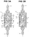
- the primary flow path has a generally axial orientation as shown by arrows A in FIG. 3A .
- a secondary flow path 38 is disposed within the second housing 30 and is in fluid communication with inlet 32 and outlet 34.
- Secondary flow path 38 has a generally helical orientation as shown by arrows B in FIGS. 2 and 3B .
- Secondary flow path 38 has a higher resistance to fluid flow than primary path 36. Secondary flow path 38 is always open.
- Valve 40 is disposed within the primary flow path 36.
- Valve 40 has a valve seat 42 and a first ball 44 and a second ball 46.
- First ball 44 is movable by gravity between a valve closed position, as shown in FIG. 3B , where the first ball 44 is in contact with valve seat 42, and a valve open position, as shown in FIG. 3A , where the first ball 44 is spaced from valve seat 42.
- First ball 44 is disposed between the second ball 46 and the valve seat 42.
- the second ball 46 is also movable by gravity between a valve closed position and a valve open position.
- Second ball 46 is larger than first ball 44.
- Second ball 46 preferably weighs more than first ball 44.
- the first ball 44 and the second ball 46 are biased by gravity.
- First ball 44 is preferably made of ruby and the second ball is typically made of tantalum metal.
- Valve seat 42 is also preferably made of ruby.
Landscapes
- Health & Medical Sciences (AREA)
- Engineering & Computer Science (AREA)
- Biomedical Technology (AREA)
- Heart & Thoracic Surgery (AREA)
- General Engineering & Computer Science (AREA)
- Anesthesiology (AREA)
- Veterinary Medicine (AREA)
- Public Health (AREA)
- General Health & Medical Sciences (AREA)
- Animal Behavior & Ethology (AREA)
- Hematology (AREA)
- Life Sciences & Earth Sciences (AREA)
- Neurology (AREA)
- Otolaryngology (AREA)
- Ophthalmology & Optometry (AREA)
- Mechanical Engineering (AREA)
- Pulmonology (AREA)
- External Artificial Organs (AREA)
- Self-Closing Valves And Venting Or Aerating Valves (AREA)
Abstract
Description
- The present invention generally relates to devices used in the treatment of hydrocephalus, and more particularly, to improvements to shunts and siphon control devises used to help divert and regulate excess fluid during the treatment therapy.
- The human brain includes four ventricles. Each ventricle contains a choroid plexus that produces cerebrospinal fluid (CSF) which bathes and cushions the brain and spinal cord within their bony and non-elastic confines.
- In a normal healthy person, CSF continuously circulates through and around the brain and its ventricles and around the spinal cord and is continuously drained away into the circulatory system so that a controlled pressure is continually maintained within the system. The CSF flows from the lateral ventricles via the foramina of Monro into the third ventricle, and then the fourth ventricle via the cerebral aqueduct in the brainstem. From there it normally can pass into the central canal of the spinal cord or into the cisterns of the subarachnoid space via three small foramina: the central foramen of Magendie and the two lateral foramina of Luschka.
- The aqueduct between the third and fourth ventricles is very small, as are the foramina and both are therefore susceptible to becoming blocked or restricted, commonly due to a birth defect, or a local growth, such as that caused by a tumor or infection, thereby disrupting the normal CSF flow. When the CSF flow is impeded, the continued production of CSF will cause an increase in intracranial pressure as the fluid collects within the ventricles.
- Alternatively, a similar increase in intracranial pressure of the patient may result from an overproduction of the CSF fluid, from a congenital malformation, or from complications of head injuries or infections, or in some cases, by malabsorption. In any case, the result is the same, an increase of CSF fluid within the ventricles and an increase in intracranial pressure. This condition is called hydrocephalus.
- When the CSF accumulates in the cerebral ventricles, the increased volume of fluid compresses the patient's brain tissue since the patient's skull will not yield to this unplanned expansion of fluid. Unfortunately, this compression destroys more and more brain tissue and a variety of secondary symptoms will become apparent in the patient as the neurological functions effectively shut down. These include, headaches, vomiting, dizziness, slurred speech, photophobia/light sensitivity, and in more severe cases, seizures, loss of consciousness and even death.
- Hydrocephalus is often treated by the insertion of a diverting catheter into the ventricles of the brain or into the lumbar cistern. Such a catheter or shunt is connected by a regulating valve to a distal catheter which shunts the CSF to another space where it can be reabsorbed and the excess pressure within the brain released. Examples of common diversion sites include the peritoneum of the abdomen via a ventriculoperitoneal shunt or lumboperitoneal shunt or the atrium of the heart via a ventriculoatrial shunt.
- A commonly used shunt to treat hydrocephalus is called the Spitz-Holter shunt. It is a conduit that is positioned between the patient's brain and the patient's heart. The device includes a tiny one-way valve that allows a controlled amount of CSF to leave the lateral ventricle of the brain and enter the heart and thereby prevent the increased pressure that causes such damage to the tissues of the brain. This device has helped millions survive this potentially fatal condition since the late 1950s.
- About 50% of the shunts fail within the first 5 years after implantation independent of the shunt operating principle and the hydrocephalus etiology. Such shunt failure requires a revision of the shunt system within the patient to avoid a return of original hydrocephalus symptoms. The main causes of failure are infection of the shunt system, obstruction of the shunt, and over-drainage and under-drainage of CSF within the shunt system.
- Over-drainage results in an excessive average flow of CFS through the shunt system. This condition may generate an abnormally low intra-cranial pressure, a collapse of the parenchyma and sub-arachnoid hemorrhage.
- Some shunt systems use a "Codman® Hakim® valve" or a "Codman® Certas™" programmable valve, which are commercially available from Codman & Shurtleff, Inc. of Raynham, MA. The Codman® Hakim® and the Codman® Certas™ valve allows a doctor to adjust the valve opening pressure non-invasively after implantation.
- Effective fluid flow rate control is particularly important since over-drainage of cerebrospinal fluid can result in dangerous conditions, including subdural hematoma. Over-drainage tends to occur when a patient moves from a horizontal position to a sitting or standing position, due to a siphon effect in the shunt system. To reduce the risk of over-drainage, some shunt systems include additional devices, sometimes referred to as anti-siphon devices, for preventing over-drainage. Some such devices use weights, which move in response to the patient changing position, to open or close the fluid flow path. One system, described in
U.S. Pat. No. 5,368,556 (Lecuyer ), includes spherical weights which provide additional compressive force against a valve spring to help maintain the valve in a closed position when the patient is sitting or standing. However, noise associated with the use of such weights may be objectionable. Other systems, such as the SIPHONGUARD® Anti-Siphon and Flow-Control Device, as described inU.S. Pat. No. 6,126,628 , provides a dual pathway, ball and spring anti-siphon device. The primary pathway is controlled by a ball 110 that is biased by a flat spring bias element 114 and a coil spring counterbias element 112. - For a shunt system with a differential pressure (DP) valve set to 100mmH2O and connected to a simple gravity actuated valve that requires 200mmH2O to open in the vertical position. The valve is calibrated to add either 0 mmH2O when horizontal or 200 mmH2O when in the vertical position. Fluid will be driven through the system and into the peritoneal (distal) catheter to drain when the differential pressure exceeds the threshold 100 mmH2O (DP valve setting) in the horizontal position or 300 mmH2O (100 mmH2O valve + 200 mmH2O anti-siphon device) when in the vertical position. The anti-siphon device will therefore prevent any fluid drainage until the 300 mmH2O threshold is exceeded.
- A drainage problem manifests itself when a patient is not completely vertical (i.e. sleeping on a pillow or bedridden), due to gravity the weighted balls will close off the single fluid pathway and prevent fluid drainage, causing a potentially high increase in the patients ICP such that severe headaches develop, or worse. This will continue until the threshold pressure of 300 mmH2O is exceeded or the anti-siphon device becomes oriented in the horizontal position to open the single fluid pathway.
- With the proposed Bi-Phase Fluid Surge Suppressor device, the above drainage problem is mitigated. With a Bi-Phase valve set to 200 mmH2O (in the vertical position), and one has a differential pressure (DP) valve set to 100mmH2O. When the patient is positioned such that the weighted balls of the Bi-Phase device close the primary pathway, the always open higher resistive secondary pathway allows CSF fluid to drain (when the threshold DP of 100 mmH2O only is exceeded).
- Should a patient stand upright (vertical position), the entire system would control the hydrostatic siphoning effect until the threshold of 300 mmH2O (100mmH2O DP valve + 200 mmH2O Bi-Phase device) is exceeded. Once exceeded, the Bi-Phase device continues to suppress the surge of fluid until the pressure decreases and the weighted balls seat themselves to close off the primary pathway, while still allowing slow gradual drainage through the secondary pathway until the differential pressure falls below the 100mmH2O DP valve setting, in this example.
-
-
FIG. 1 is a perspective view of view of a shunt system in accordance with the present invention; -
FIG. 2 is an exploded view of the siphon control device in accordance with the present invention; -
FIG. 3A is a cross-sectional view of the siphon control device in accordance with the present invention showing fluid flowing through both the primary and secondary flow paths; -
FIG. 3B is a cross-sectional view of the siphon control device in accordance with the present invention showing fluid flowing through only the secondary flow path; -
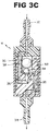
FIG. 3C is a cross-sectional view of the siphon control device in accordance with the present invention showing fluid flowing through both the primary and secondary flow paths; -
FIG. 4 is a cross-sectional view taken along line 4-4 ofFIG. 3A and looking in the direction of the arrows; -
FIG. 5 is a cross-sectional view taken along line 5-5 ofFIG. 3A and looking in the direction of the arrows; -
FIG. 6 is a cross-sectional view taken along line 6-6 ofFIG. 3A and looking in the direction of the arrows; - Referring now to
FIGS. 1-6 , ashunt system 10 is illustrated.Shunt system 10 includes aproximal catheter 12, ashunt valve 14, a siphoncontrol device 16 and adistal catheter 18.Proximal catheter 12 is a piece of tubing that is introduced in the ventricle of the brain via aburr hole 20 in the skull as shown inFIG. 1 .Proximal catheter 18 has a plurality of throughholes 22 at its distal end to permit CSF to enter into theproximal catheter 18 and to be drained from the ventricle. The proximal end ofproximal catheter 18 is connected to thehousing 24 ofshunt valve 14.Housing 24 has aninlet 26 and anoutlet 28. A flow path is disposed within thehousing 24. A spring biased valve (not shown) is disposed within the flow path in the shunt housing. - Siphon
control device 16 has asecond housing 30.Housing 30 has aninlet 32 and anoutlet 34.Inlet 32 of siphoncontrol device 16 is in fluid communication withoutlet 28 of shunt14. Aprimary flow path 36 is disposed withinsecond housing 30 and is in fluid communication withinlet 32 andoutlet 34. The primary flow path has a generally axial orientation as shown by arrows A inFIG. 3A . Asecondary flow path 38 is disposed within thesecond housing 30 and is in fluid communication withinlet 32 andoutlet 34.Secondary flow path 38 has a generally helical orientation as shown by arrows B inFIGS. 2 and3B .Secondary flow path 38 has a higher resistance to fluid flow thanprimary path 36.Secondary flow path 38 is always open. - A
valve 40 is disposed within theprimary flow path 36.Valve 40 has avalve seat 42 and afirst ball 44 and asecond ball 46.First ball 44 is movable by gravity between a valve closed position, as shown inFIG. 3B , where thefirst ball 44 is in contact withvalve seat 42, and a valve open position, as shown inFIG. 3A , where thefirst ball 44 is spaced fromvalve seat 42.First ball 44 is disposed between thesecond ball 46 and thevalve seat 42. Thesecond ball 46 is also movable by gravity between a valve closed position and a valve open position.Second ball 46 is larger thanfirst ball 44.Second ball 46 preferably weighs more thanfirst ball 44. Thefirst ball 44 and thesecond ball 46 are biased by gravity.First ball 44 is preferably made of ruby and the second ball is typically made of tantalum metal.Valve seat 42 is also preferably made of ruby.
Claims (13)
- A siphon guard comprising:a housing having an inlet and an outlet;a primary flow path disposed within the housing and in fluid communication with the inlet and the outlet;a secondary flow path disposed within the housing and in fluid communication with the inlet and the outlet, the secondary flow path having a higher resistance to fluid flow than the primary path; anda valve disposed within the primary flow path, the valve having a valve seat and a first ball and a second ball, the first ball being movable between a valve closed position where the first ball is in contact with the valve seat and a valve open position where the first ball is spaced from the valve seat, the first ball is disposed between the second ball and the valve seat, the second ball being movable between a valve closed position and a valve open position.
- The siphon guard of claim 1, wherein the second ball is larger than the first ball.
- The siphon guard of claim 2, wherein the second ball is weighs more than the first ball.
- The siphon guard of claim 1, wherein the first ball and the second ball are biased by gravity.
- The siphon guard of claim 1, wherein the second flow path is always open.
- The siphon guard of claim 1, wherein the first ball is made of ruby and the second ball is made of tantalum metal.
- A shunt and siphon guard kit comprising:a shunt having a first housing having an inlet and an outlet, a flow path disposed within the first housing;a spring biased valve being disposed within the flow path in the shunt housing;a siphon guard having a second housing having an inlet and an outlet, said inlet of the siphon guard being in fluid communication with the outlet of the shunt, a primary flow path disposed within the second housing and in fluid communication with the inlet and the outlet, the primary flow path having an axial orientation, a secondary flow path disposed within the second housing and in fluid communication with the inlet and the outlet, the secondary flow path having a higher resistance to fluid flow than the primary path; anda valve disposed within the primary flow path, the valve having a valve seat and a first ball and a second ball, the first ball being movable by gravity between a valve closed position where the first ball is in contact with the valve seat and a valve open position where the first ball is spaced from the valve seat, the first ball is disposed between the second ball and the valve seat, the second ball being movable by gravity between a valve closed position and a valve open position.
- A shunt and siphon guard kit comprising:a shunt having a first housing having an inlet and an outlet, a flow path disposed within the first housing;a spring biased valve being disposed within the flow path in the shunt housing;a siphon guard of claim 1, said inlet of the siphon guard being in fluid communication with the outlet of the shunt, and the primary flow path having an axial orientation,wherein the first ball is movable by gravity between the valve closed position and the valve open position and the second ball is movable by gravity between the valve closed position and the valve open position.
- The siphon guard of claim 7 or claim 8, wherein the second ball is larger than the first ball.
- The siphon guard of claim 8, wherein the second ball is weighs more than the first ball.
- The siphon guard of claim 7 or claim 8, wherein the first ball and the second ball are biased by gravity.
- The siphon guard of claim 7 or claim 8, wherein the second flow path is always open.
- The siphon guard of claim 7 or claim 8, wherein the first ball is made of ruby and the second ball is made of tantalum metal.
Applications Claiming Priority (1)
| Application Number | Priority Date | Filing Date | Title |
|---|---|---|---|
| US13/799,281 US20140276348A1 (en) | 2013-03-13 | 2013-03-13 | Bi-phase fluid surge suppressor device |
Publications (3)
| Publication Number | Publication Date |
|---|---|
| EP2777752A2 true EP2777752A2 (en) | 2014-09-17 |
| EP2777752A3 EP2777752A3 (en) | 2014-11-26 |
| EP2777752B1 EP2777752B1 (en) | 2021-08-25 |
Family
ID=50280163
Family Applications (1)
| Application Number | Title | Priority Date | Filing Date |
|---|---|---|---|
| EP14159178.4A Active EP2777752B1 (en) | 2013-03-13 | 2014-03-12 | Siphon guard device for hydrocephalus valve |
Country Status (5)
| Country | Link |
|---|---|
| US (2) | US20140276348A1 (en) |
| EP (1) | EP2777752B1 (en) |
| JP (1) | JP6381933B2 (en) |
| AU (1) | AU2014201231B2 (en) |
| CA (1) | CA2845564C (en) |
Families Citing this family (10)
| Publication number | Priority date | Publication date | Assignee | Title |
|---|---|---|---|---|
| WO2018184717A2 (en) | 2017-04-06 | 2018-10-11 | Christoph Miethke Gmbh & Co. Kg | Flow reducer |
| JP7000453B2 (en) | 2017-04-06 | 2022-01-19 | クリストフ ミートケ ゲゼルシャフト ミット ベシュレンクテル ハフツング ウント コンパニー コマンディトゲゼルシャフト | Flow regulator |
| US10828474B2 (en) | 2017-09-12 | 2020-11-10 | Integra LifeSciences Switzerland Sárl | Bodily fluid drainage system with volume limiting and adjustable volume capacity functionality |
| DE102018133691A1 (en) * | 2018-12-28 | 2020-07-02 | Andreas Spiegelberg | Valve for permanent implantation, especially for the treatment of normal pressure hydrocephalus disease |
| WO2021203003A1 (en) * | 2020-04-02 | 2021-10-07 | Equilibar, Llc | Mechanical valve for pressure control |
| CN116723875A (en) | 2020-10-28 | 2023-09-08 | 美敦力Ps医疗股份有限公司 | Systems and methods for valves |
| CN116723880A (en) * | 2020-10-28 | 2023-09-08 | 美敦力Ps医疗股份有限公司 | System and method for a valve |
| WO2022087896A1 (en) | 2020-10-28 | 2022-05-05 | Medtronic Xomed, Inc. | System and method for a valve |
| DE102020134312B3 (en) | 2020-12-18 | 2022-01-05 | Christoph Miethke Gmbh & Co Kg | Adjustable implantable choke |
| US20250099290A1 (en) * | 2023-09-27 | 2025-03-27 | Mihna Medical Technologies | One-way valve for urinary catheters and the like |
Citations (2)
| Publication number | Priority date | Publication date | Assignee | Title |
|---|---|---|---|---|
| US5368556A (en) | 1992-01-22 | 1994-11-29 | Cordis Corporation | Implantable drainage valve for the treatment of hydrocephalus |
| US6126628A (en) | 1997-04-22 | 2000-10-03 | Johnson & Johnson Professional, Inc. | Fluid flow limiting device |
Family Cites Families (9)
| Publication number | Priority date | Publication date | Assignee | Title |
|---|---|---|---|---|
| US3889687A (en) * | 1974-01-31 | 1975-06-17 | Donald L Harris | Shunt system for the transport of cerebrospinal fluid |
| JPS5230089A (en) * | 1975-09-01 | 1977-03-07 | Fuji System | Body fluid flow rate regulator capable of retaining in vivo |
| US4621654A (en) * | 1986-02-03 | 1986-11-11 | Holter John W | Attitude and pressure responsive valve |
| DE19535637C2 (en) * | 1995-09-26 | 1997-10-23 | Christoph Miethke | Hydrocephalus valve |
| US5634894A (en) * | 1995-12-01 | 1997-06-03 | The Nemours Foundation | Antisiphoning valve |
| FR2746658B1 (en) * | 1996-03-26 | 1998-06-19 | Cordis Sa | IMPLANTABLE DRAINAGE VALVE FOR THE TREATMENT OF HYDROCEPHALIA |
| ES2297677T3 (en) * | 2004-03-27 | 2008-05-01 | CHRISTOPH MIETHKE GMBH & CO. KG | ADJUSTABLE HYDROCEPHAL VALVE. |
| US20060089589A1 (en) * | 2004-10-21 | 2006-04-27 | Portnoy Harold D | Resistive shunt valve |
| EP2253352A1 (en) * | 2009-05-21 | 2010-11-24 | Debiotech S.A. | Passive fluid flow regulator |
-
2013
- 2013-03-13 US US13/799,281 patent/US20140276348A1/en not_active Abandoned
-
2014
- 2014-03-05 AU AU2014201231A patent/AU2014201231B2/en active Active
- 2014-03-11 CA CA2845564A patent/CA2845564C/en active Active
- 2014-03-12 JP JP2014048716A patent/JP6381933B2/en active Active
- 2014-03-12 EP EP14159178.4A patent/EP2777752B1/en active Active
-
2016
- 2016-04-25 US US15/137,687 patent/US10426937B2/en active Active
Patent Citations (2)
| Publication number | Priority date | Publication date | Assignee | Title |
|---|---|---|---|---|
| US5368556A (en) | 1992-01-22 | 1994-11-29 | Cordis Corporation | Implantable drainage valve for the treatment of hydrocephalus |
| US6126628A (en) | 1997-04-22 | 2000-10-03 | Johnson & Johnson Professional, Inc. | Fluid flow limiting device |
Also Published As
| Publication number | Publication date |
|---|---|
| AU2014201231A1 (en) | 2014-10-02 |
| CA2845564C (en) | 2021-02-16 |
| JP2014176666A (en) | 2014-09-25 |
| US10426937B2 (en) | 2019-10-01 |
| US20140276348A1 (en) | 2014-09-18 |
| AU2014201231B2 (en) | 2018-08-30 |
| US20160235951A1 (en) | 2016-08-18 |
| EP2777752B1 (en) | 2021-08-25 |
| EP2777752A3 (en) | 2014-11-26 |
| JP6381933B2 (en) | 2018-08-29 |
| CA2845564A1 (en) | 2014-09-13 |
Similar Documents
| Publication | Publication Date | Title |
|---|---|---|
| EP2777752B1 (en) | Siphon guard device for hydrocephalus valve | |
| US9033909B2 (en) | Shunt valve for treatment of hydrocephalus | |
| US4681559A (en) | Plural valve three stage pressure relief system | |
| US4675003A (en) | Three stage pressure regulator valve | |
| EP1331019B1 (en) | Inherent anti-siphon device | |
| US6126628A (en) | Fluid flow limiting device | |
| US7118549B2 (en) | Shunt system including a flow control device for controlling the flow of cerebrospinal fluid out of a brain ventricle | |
| US8177737B2 (en) | Drainage system for treating hydrocephalus | |
| CA2472658C (en) | Self-adjusting hydrocephalus valve | |
| US9381331B2 (en) | Device for regulating gravitational pressure in a shunt system | |
| US9731102B2 (en) | Adjustable resistance, gravitationally activated, anti-siphon valve | |
| JPS60139257A (en) | Three-step valve | |
| US12390624B2 (en) | Valve for permanent implantation, in particular for treatment of normal pressure hydrocephalus | |
| EP2838583A1 (en) | Improved shunt valve for controlling siphon effect | |
| CA2610650A1 (en) | Fluid flow limited device |
Legal Events
| Date | Code | Title | Description |
|---|---|---|---|
| 17P | Request for examination filed |
Effective date: 20140312 |
|
| AK | Designated contracting states |
Kind code of ref document: A2 Designated state(s): AL AT BE BG CH CY CZ DE DK EE ES FI FR GB GR HR HU IE IS IT LI LT LU LV MC MK MT NL NO PL PT RO RS SE SI SK SM TR |
|
| AX | Request for extension of the european patent |
Extension state: BA ME |
|
| PUAI | Public reference made under article 153(3) epc to a published international application that has entered the european phase |
Free format text: ORIGINAL CODE: 0009012 |
|
| PUAL | Search report despatched |
Free format text: ORIGINAL CODE: 0009013 |
|
| AK | Designated contracting states |
Kind code of ref document: A3 Designated state(s): AL AT BE BG CH CY CZ DE DK EE ES FI FR GB GR HR HU IE IS IT LI LT LU LV MC MK MT NL NO PL PT RO RS SE SI SK SM TR |
|
| AX | Request for extension of the european patent |
Extension state: BA ME |
|
| RIC1 | Information provided on ipc code assigned before grant |
Ipc: F16K 17/12 20060101ALI20141017BHEP Ipc: A61M 27/00 20060101AFI20141017BHEP |
|
| R17P | Request for examination filed (corrected) |
Effective date: 20150522 |
|
| RBV | Designated contracting states (corrected) |
Designated state(s): AL AT BE BG CH CY CZ DE DK EE ES FI FR GB GR HR HU IE IS IT LI LT LU LV MC MK MT NL NO PL PT RO RS SE SI SK SM TR |
|
| RAP1 | Party data changed (applicant data changed or rights of an application transferred) |
Owner name: INTEGRA LIFESCIENCES SWITZERLAND SARL |
|
| STAA | Information on the status of an ep patent application or granted ep patent |
Free format text: STATUS: EXAMINATION IS IN PROGRESS |
|
| 17Q | First examination report despatched |
Effective date: 20190703 |
|
| GRAP | Despatch of communication of intention to grant a patent |
Free format text: ORIGINAL CODE: EPIDOSNIGR1 |
|
| STAA | Information on the status of an ep patent application or granted ep patent |
Free format text: STATUS: GRANT OF PATENT IS INTENDED |
|
| INTG | Intention to grant announced |
Effective date: 20201112 |
|
| GRAJ | Information related to disapproval of communication of intention to grant by the applicant or resumption of examination proceedings by the epo deleted |
Free format text: ORIGINAL CODE: EPIDOSDIGR1 |
|
| STAA | Information on the status of an ep patent application or granted ep patent |
Free format text: STATUS: EXAMINATION IS IN PROGRESS |
|
| INTC | Intention to grant announced (deleted) | ||
| GRAP | Despatch of communication of intention to grant a patent |
Free format text: ORIGINAL CODE: EPIDOSNIGR1 |
|
| STAA | Information on the status of an ep patent application or granted ep patent |
Free format text: STATUS: GRANT OF PATENT IS INTENDED |
|
| INTG | Intention to grant announced |
Effective date: 20210525 |
|
| GRAS | Grant fee paid |
Free format text: ORIGINAL CODE: EPIDOSNIGR3 |
|
| GRAA | (expected) grant |
Free format text: ORIGINAL CODE: 0009210 |
|
| STAA | Information on the status of an ep patent application or granted ep patent |
Free format text: STATUS: THE PATENT HAS BEEN GRANTED |
|
| AK | Designated contracting states |
Kind code of ref document: B1 Designated state(s): AL AT BE BG CH CY CZ DE DK EE ES FI FR GB GR HR HU IE IS IT LI LT LU LV MC MK MT NL NO PL PT RO RS SE SI SK SM TR |
|
| REG | Reference to a national code |
Ref country code: GB Ref legal event code: FG4D |
|
| REG | Reference to a national code |
Ref country code: CH Ref legal event code: EP |
|
| REG | Reference to a national code |
Ref country code: IE Ref legal event code: FG4D Ref country code: AT Ref legal event code: REF Ref document number: 1423167 Country of ref document: AT Kind code of ref document: T Effective date: 20210915 |
|
| REG | Reference to a national code |
Ref country code: DE Ref legal event code: R096 Ref document number: 602014079627 Country of ref document: DE |
|
| REG | Reference to a national code |
Ref country code: LT Ref legal event code: MG9D |
|
| REG | Reference to a national code |
Ref country code: NL Ref legal event code: MP Effective date: 20210825 |
|
| REG | Reference to a national code |
Ref country code: AT Ref legal event code: MK05 Ref document number: 1423167 Country of ref document: AT Kind code of ref document: T Effective date: 20210825 |
|
| PG25 | Lapsed in a contracting state [announced via postgrant information from national office to epo] |
Ref country code: LT Free format text: LAPSE BECAUSE OF FAILURE TO SUBMIT A TRANSLATION OF THE DESCRIPTION OR TO PAY THE FEE WITHIN THE PRESCRIBED TIME-LIMIT Effective date: 20210825 Ref country code: BG Free format text: LAPSE BECAUSE OF FAILURE TO SUBMIT A TRANSLATION OF THE DESCRIPTION OR TO PAY THE FEE WITHIN THE PRESCRIBED TIME-LIMIT Effective date: 20211125 Ref country code: AT Free format text: LAPSE BECAUSE OF FAILURE TO SUBMIT A TRANSLATION OF THE DESCRIPTION OR TO PAY THE FEE WITHIN THE PRESCRIBED TIME-LIMIT Effective date: 20210825 Ref country code: ES Free format text: LAPSE BECAUSE OF FAILURE TO SUBMIT A TRANSLATION OF THE DESCRIPTION OR TO PAY THE FEE WITHIN THE PRESCRIBED TIME-LIMIT Effective date: 20210825 Ref country code: FI Free format text: LAPSE BECAUSE OF FAILURE TO SUBMIT A TRANSLATION OF THE DESCRIPTION OR TO PAY THE FEE WITHIN THE PRESCRIBED TIME-LIMIT Effective date: 20210825 Ref country code: NO Free format text: LAPSE BECAUSE OF FAILURE TO SUBMIT A TRANSLATION OF THE DESCRIPTION OR TO PAY THE FEE WITHIN THE PRESCRIBED TIME-LIMIT Effective date: 20211125 Ref country code: PT Free format text: LAPSE BECAUSE OF FAILURE TO SUBMIT A TRANSLATION OF THE DESCRIPTION OR TO PAY THE FEE WITHIN THE PRESCRIBED TIME-LIMIT Effective date: 20211227 Ref country code: HR Free format text: LAPSE BECAUSE OF FAILURE TO SUBMIT A TRANSLATION OF THE DESCRIPTION OR TO PAY THE FEE WITHIN THE PRESCRIBED TIME-LIMIT Effective date: 20210825 Ref country code: SE Free format text: LAPSE BECAUSE OF FAILURE TO SUBMIT A TRANSLATION OF THE DESCRIPTION OR TO PAY THE FEE WITHIN THE PRESCRIBED TIME-LIMIT Effective date: 20210825 Ref country code: RS Free format text: LAPSE BECAUSE OF FAILURE TO SUBMIT A TRANSLATION OF THE DESCRIPTION OR TO PAY THE FEE WITHIN THE PRESCRIBED TIME-LIMIT Effective date: 20210825 |
|
| PG25 | Lapsed in a contracting state [announced via postgrant information from national office to epo] |
Ref country code: PL Free format text: LAPSE BECAUSE OF FAILURE TO SUBMIT A TRANSLATION OF THE DESCRIPTION OR TO PAY THE FEE WITHIN THE PRESCRIBED TIME-LIMIT Effective date: 20210825 Ref country code: LV Free format text: LAPSE BECAUSE OF FAILURE TO SUBMIT A TRANSLATION OF THE DESCRIPTION OR TO PAY THE FEE WITHIN THE PRESCRIBED TIME-LIMIT Effective date: 20210825 Ref country code: GR Free format text: LAPSE BECAUSE OF FAILURE TO SUBMIT A TRANSLATION OF THE DESCRIPTION OR TO PAY THE FEE WITHIN THE PRESCRIBED TIME-LIMIT Effective date: 20211126 |
|
| PG25 | Lapsed in a contracting state [announced via postgrant information from national office to epo] |
Ref country code: NL Free format text: LAPSE BECAUSE OF FAILURE TO SUBMIT A TRANSLATION OF THE DESCRIPTION OR TO PAY THE FEE WITHIN THE PRESCRIBED TIME-LIMIT Effective date: 20210825 |
|
| PG25 | Lapsed in a contracting state [announced via postgrant information from national office to epo] |
Ref country code: DK Free format text: LAPSE BECAUSE OF FAILURE TO SUBMIT A TRANSLATION OF THE DESCRIPTION OR TO PAY THE FEE WITHIN THE PRESCRIBED TIME-LIMIT Effective date: 20210825 |
|
| REG | Reference to a national code |
Ref country code: DE Ref legal event code: R097 Ref document number: 602014079627 Country of ref document: DE |
|
| PG25 | Lapsed in a contracting state [announced via postgrant information from national office to epo] |
Ref country code: SM Free format text: LAPSE BECAUSE OF FAILURE TO SUBMIT A TRANSLATION OF THE DESCRIPTION OR TO PAY THE FEE WITHIN THE PRESCRIBED TIME-LIMIT Effective date: 20210825 Ref country code: SK Free format text: LAPSE BECAUSE OF FAILURE TO SUBMIT A TRANSLATION OF THE DESCRIPTION OR TO PAY THE FEE WITHIN THE PRESCRIBED TIME-LIMIT Effective date: 20210825 Ref country code: RO Free format text: LAPSE BECAUSE OF FAILURE TO SUBMIT A TRANSLATION OF THE DESCRIPTION OR TO PAY THE FEE WITHIN THE PRESCRIBED TIME-LIMIT Effective date: 20210825 Ref country code: EE Free format text: LAPSE BECAUSE OF FAILURE TO SUBMIT A TRANSLATION OF THE DESCRIPTION OR TO PAY THE FEE WITHIN THE PRESCRIBED TIME-LIMIT Effective date: 20210825 Ref country code: CZ Free format text: LAPSE BECAUSE OF FAILURE TO SUBMIT A TRANSLATION OF THE DESCRIPTION OR TO PAY THE FEE WITHIN THE PRESCRIBED TIME-LIMIT Effective date: 20210825 Ref country code: AL Free format text: LAPSE BECAUSE OF FAILURE TO SUBMIT A TRANSLATION OF THE DESCRIPTION OR TO PAY THE FEE WITHIN THE PRESCRIBED TIME-LIMIT Effective date: 20210825 |
|
| PLBE | No opposition filed within time limit |
Free format text: ORIGINAL CODE: 0009261 |
|
| STAA | Information on the status of an ep patent application or granted ep patent |
Free format text: STATUS: NO OPPOSITION FILED WITHIN TIME LIMIT |
|
| PG25 | Lapsed in a contracting state [announced via postgrant information from national office to epo] |
Ref country code: IT Free format text: LAPSE BECAUSE OF FAILURE TO SUBMIT A TRANSLATION OF THE DESCRIPTION OR TO PAY THE FEE WITHIN THE PRESCRIBED TIME-LIMIT Effective date: 20210825 |
|
| 26N | No opposition filed |
Effective date: 20220527 |
|
| PG25 | Lapsed in a contracting state [announced via postgrant information from national office to epo] |
Ref country code: SI Free format text: LAPSE BECAUSE OF FAILURE TO SUBMIT A TRANSLATION OF THE DESCRIPTION OR TO PAY THE FEE WITHIN THE PRESCRIBED TIME-LIMIT Effective date: 20210825 |
|
| PG25 | Lapsed in a contracting state [announced via postgrant information from national office to epo] |
Ref country code: MC Free format text: LAPSE BECAUSE OF FAILURE TO SUBMIT A TRANSLATION OF THE DESCRIPTION OR TO PAY THE FEE WITHIN THE PRESCRIBED TIME-LIMIT Effective date: 20210825 |
|
| REG | Reference to a national code |
Ref country code: BE Ref legal event code: MM Effective date: 20220331 |
|
| PG25 | Lapsed in a contracting state [announced via postgrant information from national office to epo] |
Ref country code: LU Free format text: LAPSE BECAUSE OF NON-PAYMENT OF DUE FEES Effective date: 20220312 Ref country code: IE Free format text: LAPSE BECAUSE OF NON-PAYMENT OF DUE FEES Effective date: 20220312 |
|
| PG25 | Lapsed in a contracting state [announced via postgrant information from national office to epo] |
Ref country code: BE Free format text: LAPSE BECAUSE OF NON-PAYMENT OF DUE FEES Effective date: 20220331 |
|
| P01 | Opt-out of the competence of the unified patent court (upc) registered |
Effective date: 20230522 |
|
| PG25 | Lapsed in a contracting state [announced via postgrant information from national office to epo] |
Ref country code: HU Free format text: LAPSE BECAUSE OF FAILURE TO SUBMIT A TRANSLATION OF THE DESCRIPTION OR TO PAY THE FEE WITHIN THE PRESCRIBED TIME-LIMIT; INVALID AB INITIO Effective date: 20140312 |
|
| PG25 | Lapsed in a contracting state [announced via postgrant information from national office to epo] |
Ref country code: MK Free format text: LAPSE BECAUSE OF FAILURE TO SUBMIT A TRANSLATION OF THE DESCRIPTION OR TO PAY THE FEE WITHIN THE PRESCRIBED TIME-LIMIT Effective date: 20210825 Ref country code: CY Free format text: LAPSE BECAUSE OF FAILURE TO SUBMIT A TRANSLATION OF THE DESCRIPTION OR TO PAY THE FEE WITHIN THE PRESCRIBED TIME-LIMIT Effective date: 20210825 |
|
| PG25 | Lapsed in a contracting state [announced via postgrant information from national office to epo] |
Ref country code: MT Free format text: LAPSE BECAUSE OF FAILURE TO SUBMIT A TRANSLATION OF THE DESCRIPTION OR TO PAY THE FEE WITHIN THE PRESCRIBED TIME-LIMIT Effective date: 20210825 |
|
| PGFP | Annual fee paid to national office [announced via postgrant information from national office to epo] |
Ref country code: CH Payment date: 20250401 Year of fee payment: 12 |
|
| PG25 | Lapsed in a contracting state [announced via postgrant information from national office to epo] |
Ref country code: TR Free format text: LAPSE BECAUSE OF FAILURE TO SUBMIT A TRANSLATION OF THE DESCRIPTION OR TO PAY THE FEE WITHIN THE PRESCRIBED TIME-LIMIT Effective date: 20210825 |
|
| PGFP | Annual fee paid to national office [announced via postgrant information from national office to epo] |
Ref country code: FR Payment date: 20251231 Year of fee payment: 13 |
|
| PGFP | Annual fee paid to national office [announced via postgrant information from national office to epo] |
Ref country code: GB Payment date: 20260106 Year of fee payment: 13 |
|
| PGFP | Annual fee paid to national office [announced via postgrant information from national office to epo] |
Ref country code: DE Payment date: 20260102 Year of fee payment: 13 |