EP2777610A2 - Système de prothèse endoluminale - Google Patents
Système de prothèse endoluminale Download PDFInfo
- Publication number
- EP2777610A2 EP2777610A2 EP14275054.6A EP14275054A EP2777610A2 EP 2777610 A2 EP2777610 A2 EP 2777610A2 EP 14275054 A EP14275054 A EP 14275054A EP 2777610 A2 EP2777610 A2 EP 2777610A2
- Authority
- EP
- European Patent Office
- Prior art keywords
- extension
- graft
- leg
- lumen
- main
- Prior art date
- Legal status (The legal status is an assumption and is not a legal conclusion. Google has not performed a legal analysis and makes no representation as to the accuracy of the status listed.)
- Granted
Links
Images


Classifications
-
- A—HUMAN NECESSITIES
- A61—MEDICAL OR VETERINARY SCIENCE; HYGIENE
- A61F—FILTERS IMPLANTABLE INTO BLOOD VESSELS; PROSTHESES; DEVICES PROVIDING PATENCY TO, OR PREVENTING COLLAPSING OF, TUBULAR STRUCTURES OF THE BODY, e.g. STENTS; ORTHOPAEDIC, NURSING OR CONTRACEPTIVE DEVICES; FOMENTATION; TREATMENT OR PROTECTION OF EYES OR EARS; BANDAGES, DRESSINGS OR ABSORBENT PADS; FIRST-AID KITS
- A61F2/00—Filters implantable into blood vessels; Prostheses, i.e. artificial substitutes or replacements for parts of the body; Appliances for connecting them with the body; Devices providing patency to, or preventing collapsing of, tubular structures of the body, e.g. stents
- A61F2/02—Prostheses implantable into the body
- A61F2/04—Hollow or tubular parts of organs, e.g. bladders, tracheae, bronchi or bile ducts
- A61F2/06—Blood vessels
- A61F2/07—Stent-grafts
-
- A—HUMAN NECESSITIES
- A61—MEDICAL OR VETERINARY SCIENCE; HYGIENE
- A61F—FILTERS IMPLANTABLE INTO BLOOD VESSELS; PROSTHESES; DEVICES PROVIDING PATENCY TO, OR PREVENTING COLLAPSING OF, TUBULAR STRUCTURES OF THE BODY, e.g. STENTS; ORTHOPAEDIC, NURSING OR CONTRACEPTIVE DEVICES; FOMENTATION; TREATMENT OR PROTECTION OF EYES OR EARS; BANDAGES, DRESSINGS OR ABSORBENT PADS; FIRST-AID KITS
- A61F2/00—Filters implantable into blood vessels; Prostheses, i.e. artificial substitutes or replacements for parts of the body; Appliances for connecting them with the body; Devices providing patency to, or preventing collapsing of, tubular structures of the body, e.g. stents
- A61F2/95—Instruments specially adapted for placement or removal of stents or stent-grafts
- A61F2/954—Instruments specially adapted for placement or removal of stents or stent-grafts for placing stents or stent-grafts in a bifurcation
-
- A—HUMAN NECESSITIES
- A61—MEDICAL OR VETERINARY SCIENCE; HYGIENE
- A61F—FILTERS IMPLANTABLE INTO BLOOD VESSELS; PROSTHESES; DEVICES PROVIDING PATENCY TO, OR PREVENTING COLLAPSING OF, TUBULAR STRUCTURES OF THE BODY, e.g. STENTS; ORTHOPAEDIC, NURSING OR CONTRACEPTIVE DEVICES; FOMENTATION; TREATMENT OR PROTECTION OF EYES OR EARS; BANDAGES, DRESSINGS OR ABSORBENT PADS; FIRST-AID KITS
- A61F2/00—Filters implantable into blood vessels; Prostheses, i.e. artificial substitutes or replacements for parts of the body; Appliances for connecting them with the body; Devices providing patency to, or preventing collapsing of, tubular structures of the body, e.g. stents
- A61F2/02—Prostheses implantable into the body
- A61F2/04—Hollow or tubular parts of organs, e.g. bladders, tracheae, bronchi or bile ducts
- A61F2/06—Blood vessels
- A61F2002/061—Blood vessels provided with means for allowing access to secondary lumens
-
- A—HUMAN NECESSITIES
- A61—MEDICAL OR VETERINARY SCIENCE; HYGIENE
- A61F—FILTERS IMPLANTABLE INTO BLOOD VESSELS; PROSTHESES; DEVICES PROVIDING PATENCY TO, OR PREVENTING COLLAPSING OF, TUBULAR STRUCTURES OF THE BODY, e.g. STENTS; ORTHOPAEDIC, NURSING OR CONTRACEPTIVE DEVICES; FOMENTATION; TREATMENT OR PROTECTION OF EYES OR EARS; BANDAGES, DRESSINGS OR ABSORBENT PADS; FIRST-AID KITS
- A61F2/00—Filters implantable into blood vessels; Prostheses, i.e. artificial substitutes or replacements for parts of the body; Appliances for connecting them with the body; Devices providing patency to, or preventing collapsing of, tubular structures of the body, e.g. stents
- A61F2/02—Prostheses implantable into the body
- A61F2/04—Hollow or tubular parts of organs, e.g. bladders, tracheae, bronchi or bile ducts
- A61F2/06—Blood vessels
- A61F2002/065—Y-shaped blood vessels
- A61F2002/067—Y-shaped blood vessels modular
-
- A—HUMAN NECESSITIES
- A61—MEDICAL OR VETERINARY SCIENCE; HYGIENE
- A61F—FILTERS IMPLANTABLE INTO BLOOD VESSELS; PROSTHESES; DEVICES PROVIDING PATENCY TO, OR PREVENTING COLLAPSING OF, TUBULAR STRUCTURES OF THE BODY, e.g. STENTS; ORTHOPAEDIC, NURSING OR CONTRACEPTIVE DEVICES; FOMENTATION; TREATMENT OR PROTECTION OF EYES OR EARS; BANDAGES, DRESSINGS OR ABSORBENT PADS; FIRST-AID KITS
- A61F2/00—Filters implantable into blood vessels; Prostheses, i.e. artificial substitutes or replacements for parts of the body; Appliances for connecting them with the body; Devices providing patency to, or preventing collapsing of, tubular structures of the body, e.g. stents
- A61F2/02—Prostheses implantable into the body
- A61F2/04—Hollow or tubular parts of organs, e.g. bladders, tracheae, bronchi or bile ducts
- A61F2/06—Blood vessels
- A61F2/07—Stent-grafts
- A61F2002/075—Stent-grafts the stent being loosely attached to the graft material, e.g. by stitching
Definitions
- This disclosure relates to medical devices for implantation within the human or animal body for treatment of an endovascular condition. More particularly, it relates to an endoluminal prosthesis system suitable for treating a thoracic aorta of a patient.
- Endovascular methods have been proposed for treatment of aneurysms of the aorta, particularly when an aneurysm is adjacent to the aortic bifurcation. But when an aneurysm occurs higher up in the aorta, for example, in the region of the descending aorta adjacent to the thoracic arch or in the ascending aorta, endovascular techniques for treating these aneurysms are somewhat more difficult because of the arched nature of the thoracic arch, the existence of major arteries in the region, and the proximity to the heart.
- the surgical Bentall technique has been demonstrated with some success for treating ascending aortic aneurysms. But the Bentall technique may be used only in patients able to tolerate a fully surgical technique and thus is not suitable for patients that may be intolerant of such an invasive procedure.
- the present invention seeks to provide an improved endoluminal prosthesis and systems and methods for facilitating deployment of such a prosthesis.
- an endoluminal prosthesis system may include a main graft and an extension graft.
- the main graft may include a tubular main body having a sidewall, an open proximal end, an open distal end, a lumen extending longitudinally between the proximal end and the distal end, and a fenestration in the sidewall.
- the extension graft may include a tubular extension body, a tubular first extension leg, and a tubular second extension leg.
- the extension body may include an open first end, a second end, and a lumen extending longitudinally between the first end and the second end.
- Each of the first extension leg and the second extension leg may extend from the extension body and include a first end, a second end, and a lumen in fluid communication with the lumen of the extension body.
- the extension graft may be deployable within the main graft such that the extension body extends through the fenestration in the sidewall of the main body.
- Each of the first extension leg and the second extension leg may extend outward away from the main graft.
- an endoluminal prosthesis system may include a main graft and an extension graft.
- the main graft may include a tubular main body including a sidewall, an open proximal end, an open distal end, a lumen extending longitudinally between the proximal end and the distal end, and a fenestration in the sidewall.
- the extension graft may include a tubular extension body, a tubular first extension leg, and a tubular second extension leg.
- the extension body may include an open first end, a second end, and a lumen extending longitudinally between the first end and the second end.
- Each of the first extension leg and the second extension leg may extend from the extension body and include a first end, a second end, and a lumen in fluid communication with the lumen of the extension body.
- An auxiliary guide such as a guide wire or a catheter or cannula, may be preloaded in the extension graft and extend through each of the lumen of the second extension leg and the lumen of the extension body.
- the extension graft may be positionable within the main graft such that the extension body extends through the fenestration in the sidewall of the main body, each of the first extension leg and the second extension leg extends outward away from the main graft, and an end or portion of the auxiliary guide is disposed within the lumen of the main g raft.
- a method of deploying a prosthesis system may include deploying a main graft.
- the main graft may include a tubular main body including a sidewall, an open proximal end, an open distal end, a lumen extending longitudinally between the proximal end and the distal end, and a fenestration in the sidewall.
- An extension graft may be deployed within the main graft.
- the extension graft may include a tubular extension body disposed within the fenestration of the main graft, a tubular first extension leg, and a tubular second extension leg. Each of the first extension leg and the second extension leg may extend from the extension body outward away from the main graft.
- An end of an auxiliary guide wire disposed within the lumen of the main graft may be snared.
- the auxiliary guide wire may extend through a lumen of the extension body and a lumen of the second extension leg.
- An introducer may be advanced over the end of the auxiliary guide wire and into the second extension leg.
- a branch extension graft may be deployed within the second extension leg with the introducer.
- the present disclosure relates to an endoluminal prosthesis system for implantation within a human or animal body for repair of damaged vessels, ducts, or other physiological pathways and methods for delivering and deploying such an endoluminal prosthesis.
- the embodiments described in this disclosure will be discussed generally in relation to an endoluminal prosthesis system for deployment into the aortic arch, but the disclosure is not so limited and can be applied to other portions of the aorta or to other vasculature or other body vessels or lumens.
- proximal refers to a direction that is generally closest to the heart during a medical procedure
- distal refers to a direction that is farthest from the heart during a medical procedure
- An endoluminal prosthesis system may include a main graft and an extension graft.
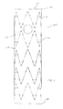
- FIG. 1 illustrates one example of a main graft 100
- FIG. 2 illustrates one example of an extension graft 200.
- the main graft may be configured for placement in an aortic arch as further described below. To that end, the main graft may be configured to extend from an ascending aorta, over the aortic arch, and into a descending aorta.
- the extension graft may be deployable within the main graft as further described below. To that end, the extension graft may be configured to extend from the main graft toward one or more branch vessels such as an innominate artery, a left common carotid artery, and/or a left subclavian artery.
- the main graft 100 may include a tubular main body 102 including a sidewall 104 of a biocompatible graft material.
- the main body 102 may include a proximal end opening at a proximal end 106, a distal end opening at a distal end 108, and a lumen 110 extending longitudinally within the main body.
- the main body 102 may include a support structure 112 attached to the sidewall 104 (e.g., attached to an inner surface and/or an outer surface of the sidewall).
- the main body 102 may include one or more fenestrations in the sidewall 104.
- the main body 102 may include a fenestration 114 as shown in FIG. 1 .
- the fenestration 114 may be configured as an opening through the sidewall 104 from the interior of the prosthesis to the exterior of the prosthesis.
- the fenestration 114 may have any suitable geometry including, for example, circular, semi-circular, oval, or oblong.
- the fenestration 114 may be positioned near the proximal end 106 of the main body 102.
- the main body 102 is described herein as including one fenestration 114, this disclosure is not so limited.
- the main body may include any number (e.g., one, three, or more) of fenestrations.
- the main body may include two fenestrations as described below with reference to FIGS. 4-7 .
- the number of fenestrations may be selected according to the number of branch vessels in the region in which the main graft is to be implanted as further described below.
- the main body may include one or more tubular extensions extending from the one or more fenestrations as described below with reference to FIGS. 4-7 .
- the extension graft 200 may be configured as a branched or bifurcated graft.
- the extension graft 200 may include a tubular extension body 210, a tubular first extension leg 220, and a tubular second extension leg 230 as shown in FIG. 2 .
- the extension body 210 may include a sidewall 211 of a biocompatible graft material.
- the extension body 210 may include a proximal end opening at a proximal end 212, a distal end opening at a distal end 214, and a lumen 216 extending longitudinally within the extension body.
- the extension body 210 may include a support structure 218 attached to the sidewall 211 (e.g., attached to an inner surface and/or an outer surface of the sidewall).
- the first extension leg 220 may include a sidewall 221 of a biocompatible graft material.
- the first extension leg 220 may include a proximal end opening at a proximal end 222, a distal end opening at a distal end 224, and a lumen 226 extending longitudinally within the first extension leg.
- the first extension leg 220 may include a support structure 228 attached to the sidewall 221 (e.g., attached to an inner surface and/or an outer surface of the sidewall).
- the second extension leg 230 may include a sidewall 231 of a biocompatible graft material.
- the second extension leg 230 may include a proximal end opening at a proximal end 232, a distal end opening at a distal end 234, and a lumen 236 extending longitudinally within the second extension leg.
- the second extension leg 230 may include a support structure 238 attached to the sidewall 231 (e.g., attached to an inner surface and/or an outer surface of the sidewall).
- the extension body 210, the first extension leg 220, and/or the second extension leg 230 may be formed as a unitary structure or as two or more independent structures joined to one another to form the extension graft 200.
- the extension body 210 and the first extension leg 220 may be formed as a unitary tubular structure, and the second extension leg 230 may be formed separately and joined to the unitary tubular structure to form the extension graft 200 as shown in FIG. 2 .
- the extension body, the first extension leg, and the second extension leg may be formed as a unitary structure, or each of the extension body, the first extension leg, and the second extension leg may be formed separately and joined to one another.
- first extension leg 220 and the second extension leg 230 may extend from the extension body 210.
- first extension leg 220 may extend from the distal end 214 of the extension body 210 as shown in FIG. 2 .
- second extension leg 230 may extend from the sidewall 211 of the extension body 210 as shown in FIG. 2 .
- both the first extension leg and the second extension leg may extend from the distal end of the extension body as described below with reference to FIG. 8 .
- both the first extension leg and the second extension leg may extend from the sidewall of the extension body or one of the first extension leg and the second extension leg may extend from the distal end of the extension body, and the other of the first extension leg and the second extension leg may extend from the sidewall of the extension body.
- the proximal end opening of the first extension leg 220 may be fluidly coupled to the distal end opening of the extension body 210.
- the proximal end 222 of the first extension leg 220 may be attached to the sidewall 211 of the extension body 210 adjacent to the distal end opening thereof such that the proximal end opening of the first extension leg is fluidly coupled to the distal end opening of the extension body.
- the lumen 226 of the first extension leg 220 may be in fluid communication with the lumen 216 of the extension body 210.
- the lumen 216 of the extension body 210 and the lumen 226 of the first extension leg 220 may collectively form a continuous flow path between the proximal end 212 of the extension body and the distal end 224 of the first extension leg.
- the first extension leg 220 may extend distally from the distal end 214 of the extension body 210 as shown in FIG. 2 .
- the first extension leg 220 may have a diameter that is substantially the same as a diameter of the extension body 210.
- the diameter of the first extension leg 220 may be substantially constant along the length thereof. In another embodiment, the diameter of the first extension leg 220 may taper along the length thereof.
- the diameter of the first extension leg 220 may decrease from a first diameter that is substantially the same as a diameter of the extension body 210 at the proximal end 222 to a second diameter at a position distal of the proximal end of the first extension leg.
- the second diameter may be smaller than the first diameter.
- the extension body 210 may have a diameter sized to supply blood flow to two branch vessels, while the first extension leg 220 may have a smaller diameter sized to supply blood to one of the two branch vessels. Blood may be supplied to the other of the two branch vessels by the second extension leg 230 as described below.
- the second diameter may be larger than the first diameter.
- the first extension leg 220 and the main body 210 may be coaxial with one another.
- the extension body 210 may include a fenestration 213 in the sidewall 211 near the distal end 214 thereof.
- the proximal end opening of the second extension leg 230 may be fluidly coupled to the fenestration of the extension body 210.
- the proximal end 232 of the second extension leg 230 may be attached to the sidewall 211 of the extension body 210 adjacent to the fenestration thereof such that the proximal end opening of the second extension leg is fluidly coupled to the fenestration of the extension body.
- the lumen 236 of the second extension leg 230 may be in fluid communication with the lumen 216 of the extension body 210.
- the lumen 216 of the extension body 210 and the lumen 236 of the second extension leg 230 may collectively form a continuous flow path between the proximal end 212 of the extension body and the distal end 234 of the second extension leg.
- the second extension leg 230 may extend distally and radially outward from the extension body 210 as shown in FIG. 2 .
- the second extension leg 230 may extend away from the sidewall 211 of the extension body 210 and/or the sidewall 221 of the first extension leg 220 at any angle (e.g., an acute angle as shown in FIG. 2 ).
- the second extension leg may extend circumferentially around the extension body and/or the first extension leg.
- the second extension leg may extend at least partially around the extension body and/or the first extension leg in a spiral or helical configuration.
- the second extension leg 230 may have a diameter that is smaller than a diameter of the extension body 210.
- the extension body 210 may have a diameter sized to supply blood flow to two branch vessels, and the second extension leg 230 may have a smaller diameter sized to supply blood flow to one of the two branch vessels. Blood flow may be supplied to the other of the two branch vessels by the first extension leg 220 as described below.
- the second extension leg may have a diameter that is substantially the same or larger than the diameter of the extension body.
- the diameter of the second extension leg 230 may be substantially constant along the length thereof.
- the diameter of the second extension leg 230 may taper along the length thereof.
- the diameter of the second extension leg 230 may taper from a first diameter at the proximal end 232 to a second diameter at a position distal of the proximal end of the second extension leg.
- the second diameter may be smaller than the first diameter.
- the second diameter may be larger than the first diameter.
- the first extension leg 220 may extend farther distally than the second extension leg 230 as shown in FIG. 2 .
- the distal end 224 of the first extension leg 220 may be positioned distal of the distal end 234 of the second extension leg 230.
- the first extension leg 220 may be longer than the second extension leg 230. This may enable the first extension leg 220 to extend into a first branch vessel while the second extension leg 230 extends toward, but not into a second branch vessel as described below.
- the second extension leg may extend farther distally than the first extension leg, or the first extension leg and the second extension leg may extend distally substantially the same distance.
- the main graft 100 may be configured for deployment within the thoracic arch as shown in FIG. 3 .
- the main graft 100 may extend from the ascending aorta 302, through the thoracic arch 304, and into the descending aorta 306.
- the main graft 100 may be deployed within the thoracic arch using any suitable endovascular technique such as, for example, that described below with reference to deployment of the main graft 400 as shown in FIGS. 10-15 .
- the extension graft 200 may be deployable within the main graft 100 as shown in FIG. 3 .
- the extension graft 200 may be deployed within the main graft 100 using any suitable endovascular technique such as, for example, those described below with reference to deployment of the extension graft 500 as shown in FIGS. 10-15 .
- the extension graft may be disposed within the fenestration 114 of the main graft as shown in FIG. 3 .
- the extension body 210 may extend through the fenestration 114 of the main graft 100 such that the proximal end 212 of the extension body is disposed within the lumen 110 of the main graft and the distal end 214 of the extension body is disposed external of the main graft.
- a portion of the sidewall 104 of the main body 102 adjacent to the fenestration 114 may be engaged by the exterior surface of the sidewall 211 of the extension body 210.
- a substantially fluid-tight connection may be established between the main graft 100 and the extension graft 200 to inhibit fluid from leaking out of the prosthesis system at the interface between the main graft and the extension graft.
- the main graft may include a tubular extension coupled to the fenestration as described below with reference to FIGS. 4-7 , which may increase the contact area between the main graft and the extension graft to further inhibit leakage of fluid from the prosthesis system.
- One or more branch vessels may branch off of the aorta in the region of the thoracic arch 304.
- the branch vessels may include an innominate artery 308, a left common carotid artery 310, and a left subclavian artery 312 as shown in FIG. 3 .
- the first extension leg 220 of the extension graft 200 may extend outward away from the main graft 100.
- the first extension leg 220 may extend toward a first branch vessel.
- the first extension leg 220 may extend a sufficiently long distance away from the main graft 100 to extend into the first branch vessel.
- the first extension leg 220 may extend away from the main graft 100 and into the innominate artery 308 as shown in FIG. 3 .
- first extension leg may extend a sufficiently short distance toward the first branch vessel such that the first extension leg does not enter the first branch vessel.
- a branch extension graft may be used to couple the first extension leg to the first branch vessel as described below. In other examples, the first extension leg may extend toward and/or into any other branch vessel.
- the second extension leg 230 may extend outward away from the main graft 100.
- the second extension leg 230 may extend toward a second branch vessel.
- the second branch vessel may be positioned adjacent to the first branch vessel.
- the second extension leg 230 may extend a sufficiently short distance away from the main graft 100 such that the second extension leg does not enter the second branch vessel.
- the second extension leg 230 may extend away from the main graft 100 toward the left common carotid artery 310 as shown in FIG. 3 .
- a branch extension graft 240 may be used to couple the second extension leg 230 to the left common carotid artery 310 as described below.
- a continuous flow path may be established from the lumen 110 of the main graft 100 into the left common carotid artery 310 through the extension graft 200 (e.g., through the lumen 216 of the extension body 210 and the lumen 236 of the second extension leg 230).
- the second extension leg may extend a sufficiently long distance toward the second branch vessel to extend into the second branch vessel. In other examples, the second extension leg may extend toward and/or into any other branch vessel.
- the configuration of the extension graft 200 may enable the extension graft to be deployed within the main graft 100 to fluidly couple the main graft to two branch vessels (e.g., two adjacent branch vessels) through a single fenestration 114. This may reduce the amount of time which may be required to couple the main graft to the two branch vessels (e.g., because a single extension graft may be used to couple the main graft to the two branch vessels instead of deploying two separate extension grafts within the main graft).
- the main graft 100 may block and/or substantially prevent blood flow from the thoracic arch 304 into the left subclavian artery 312 as shown in FIG. 3 .
- an anastomosis 314 may be provided between the left common carotid artery 310 and the left subclavian artery 312.
- the anastomosis 314 may be provided using any suitable technique.
- the anastomosis 314 may be provided in a preparatory operation prior to deployment of the prosthesis system.
- FIG. 4 illustrates another example of a main graft 400.
- the main graft 400 may be configured generally as described in International Patent App. Pub. No. WO 2011/100290 , which is incorporated by reference herein in its entirety.
- the main graft 400 may include a tubular main body 402 including a sidewall 404 of a biocompatible graft material.
- the main body 402 may include a proximal end opening at a proximal end 406, a distal end opening at a distal end 408, and a lumen 410 extending longitudinally within the main body.
- the main body 402 may include a support structure 412 attached to the sidewall 404.
- the main body 402 may include one or more fenestrations in the sidewall 404.
- the main body 402 may include a first fenestration 414a and a second fenestration 414b as shown in FIG. 4 .
- FIG. 5 illustrates a view into the lumen 410 of the main body 402 from the proximal end 406, and FIG. 6 illustrates a longitudinal cross sectional view of the main graft 400.
- the main graft 400 may include one or more tubular extensions extending from the sidewall 404.
- the main graft 400 may include a first tubular extension 416a and a second tubular extension 416b as shown in FIGS. 5-6 .
- the main graft 400 is described herein as including two fenestrations and two tubular extensions, this disclosure is not so limited.
- the main graft may include any number (e.g., one, three, or more) of fenestrations and any number (e.g., one, three, or more) of tubular extensions.
- the number of tubular extensions may be the same as or different than the number of fenestrations.
- a tubular extension may be coupled to each fenestration as shown in FIGS. 5-6 and further described below.
- one or more fenestrations may be free of a corresponding tubular extension.
- the number of fenestrations and/or tubular extensions may be selected according to the number of branch vessels in the region in which the main graft is to be implanted.
- the first tubular extension 416a may include a first end 418a, a second end 420a, and a lumen 422a extending longitudinally within the first tubular extension.
- the first tubular extension 416a may be fluidly coupled to the first fenestration 414a.
- the first end 418a may be coupled to the sidewall 404 adjacent to the first fenestration 414a such that the lumen 422a of the first tubular extension 416a is in fluid communication with the first fenestration 414a.
- the first tubular extension 416a may be disposed within the lumen 410 of the main body 402.
- the first tubular extension 416a may extend proximally from the sidewall 404 toward the proximal end 406 of the main body 402 as shown in FIGS. 5-6 . In another embodiment, the first tubular extension may extend distally from the sidewall.
- the second tubular extension 416b may include a first end 418b, a second end 420b, and a lumen 422b extending longitudinally within the second tubular extension.
- the second tubular extension 416b may be fluidly coupled to the second fenestration 414b.
- the first end 416b may be coupled to the sidewall 404 adjacent to the second fenestration 414b such that the lumen 422b of the second tubular extension 416b is in fluid communication with the second fenestration 414b.
- the second tubular extension 416b may be disposed within the lumen 410 of the main body 402.
- the second tubular extension 416b may extend proximally from the sidewall 404 toward the proximal end 406 of the main body 402 as shown in FIGS. 5-6 . In another embodiment, the second tubular extension may extend distally from the sidewall.
- the first tubular extension 416a and the second tubular extension 416b may be disposed adjacent to one another as shown in FIGS. 5-6 .
- the first tubular extension 416a and/or the second tubular extension 416b may be formed from a biocompatible graft material, which may be the same as or different than the biocompatible graft material of the sidewall 404.
- the first tubular extension 416a and/or the second tubular extension 416b may be formed integrally with the sidewall 404.
- the first tubular extension 416a and/or the second tubular extension 416b may be formed separately and attached to the sidewall 404 (e.g., by sutures, adhesive, staples, clips, or any other suitable attachment mechanism).
- the first tubular extension 416a and/or the second tubular extension 416b may include a support structure.
- the main body 402 may include one or more recesses in the sidewall 404.
- the main body 402 may include a first recess 424a and a second recess 424b as shown in FIG. 4 .
- Each recess may be configured as a dimple or depression in the sidewall 402.
- each recess may be positioned between adjacent struts and bends of the support structure 412 (e.g., openings in the support structure).
- Each recess may extend inward into the lumen 410 of the main body 402.
- the first recess 424a and/or the second recess 424b may be formed integrally with the sidewall 404.
- the first recess 424a and/or the second recess 424b may be formed separately and attached to the sidewall 404 (e.g., by sutures, adhesive, staples, clips, or any other suitable attachment mechanism).
- the first fenestration 414a may be positioned within the first recess 424a as shown in FIG. 4 . Additionally, or alternatively, the second fenestration 414b may be positioned within the second recess 424b.
- the first tubular extension 416a may extend from the first recess 424a as shown in FIGS. 5-6 .. Additionally, or alternatively, the second tubular extension 416b may extend from the second recess 424b.
- the recesses may provide space between the sidewall 404 and the body vessel wall to aid in deployment of the extension graft as further described below.
- the main graft 400 is described herein as including two recesses, this disclosure is not so limited. In other examples, the main graft may include any number (e.g., one, three, or more) of recesses. The number of recesses may be the same as or different than the number of fenestrations.
- the main body 402 of the main graft 400 may be tapered as shown in FIG. 7 .
- the diameter of the main body 402 may decrease in a proximal to distal longitudinal direction along at least a portion of the length of the main body.
- the main body 402 may have a diameter of between about 35 mm and about 50 mm near the proximal end 406 and/or a diameter of between about 30 mm and about 40 mm near the distal end 408.
- the main body 402 may have any suitable diameter (e.g., for placement within any suitable body vessel).
- An intermediate portion of the main body 402 may taper from a first diameter to a second diameter in the proximal to distal longitudinal direction.
- the first diameter may be larger than the second diameter as shown in FIG. 7 . In another embodiment, the first diameter may be smaller than the second diameter.
- the fenestrations and/or the recesses may be positioned within the intermediate portion of the main body 402 as shown in FIGS. 4-7 .
- FIG. 8 illustrates another example of an extension graft 500.
- the extension graft 500 may be similar to the extension graft 200 described above with reference to FIG. 2 .
- the extension graft 500 may include a tubular extension body 510, a tubular first extension leg 520, and a tubular second extension leg 530.
- the extension body 510 may include a sidewall 511 of a biocompatible graft material.
- the extension body 510 may include a proximal end opening at a proximal end 512, a distal end opening at a distal end 514, and a lumen 516 extending longitudinally within the extension body.
- the extension body 510 may include a support structure 518 attached to the sidewall 511 (e.g., attached to an inner surface and/or an outer surface of the sidewall).
- the first extension leg 520 may include a sidewall 521 of a biocompatible graft material.
- the first extension leg 520 may include a proximal end opening at a proximal end 522, a distal end opening at a distal end 524, and a lumen 526 extending longitudinally within the first extension leg.
- the first extension leg 520 may include a support structure 528 attached to the sidewall 521 (e.g., attached to an inner surface and/or an outer surface of the sidewall).
- the second extension leg 530 may include a sidewall 531 of a biocompatible graft material.
- the second extension leg 530 may include a proximal end opening at a proximal end 532, a distal end opening at a distal end 534, and a lumen 536 extending longitudinally within the second extension leg.
- the second extension leg 530 may include a support structure 538 attached to the sidewall 531 (e.g., attached to an inner surface and/or an outer surface of the sidewall).
- the extension body 510, the first extension leg 520, and/or the second extension leg 530 may be formed as a unitary structure or as two or more independent structures joined to one another to form the extension graft 500.
- Each of the first extension leg 520 and the second extension leg 530 may extend from the extension body 510.
- each of the first extension leg 520 and the second extension leg 530 may extend from the distal end 514 of the extension body 510 as shown in FIG. 8 .
- each of the proximal end opening of the first extension leg 520 and the proximal end opening of the second extension leg 230 may be fluidly coupled to the distal end opening of the extension body 510.
- the first extension leg 520 and the second extension leg 530 of the prosthesis 500 may be positioned adjacent to one another with each of the proximal end 522 of the first extension leg and the proximal end 532 of the second extension leg attached to the distal end 514 of the extension body 510.
- the first extension leg 520 may extend from the extension body 510 in a first direction to a first side of the extension body, and the second extension leg 530 may extend from the extension body in a second direction to a second side of the extension body opposite the first side as shown in FIG. 8 .
- the first extension leg 520 and the second extension leg 530 may extend from the extension body 510 such that the extension graft 500 is substantially "Y" shaped, with the first extension leg and the second extension leg forming the arms of the "Y" shape as shown in FIG. 8 .
- the first extension leg 520 and the second extension leg 530 may extend away from the extension body 510 and one another to form the arms of the "Y" shape.
- the extension graft 500 may be configured as a bifurcated prosthesis.
- the proximal end 522 of the first extension leg 520 may be attached to the proximal end 532 of the second extension leg 530 (e.g., at the intersection of the two arms of the "Y" shape) at a bifurcation.
- the lumen 526 of the first extension leg 520 and/or the lumen 536 of the second extension leg 530 may be in fluid communication with the lumen 516 of the extension body 510 to form a continuous flow path between the proximal end 512 of the extension body and the distal end 524 of the first extension leg and/or the distal end 534 of the second extension leg.
- the first extension leg 520 and/or the second extension leg 530 may have a diameter that is smaller than a diameter of the extension body 510.
- the extension body 510 may have a diameter sized to supply blood flow to two branch vessels, and the first extension leg 520 and/or the second extension leg 530 may have a smaller diameter sized to supply blood flow to one of the two branch vessels.
- first extension leg and/or the second extension leg may have a diameter that is substantially the same or larger than the diameter of the extension body.
- the diameter of the first extension leg 520 and/or the second extension leg 530 may be substantially constant along the length thereof. In another embodiment, the diameter of the first extension leg and/or the second extension leg may taper along the length thereof.
- the first extension leg 520 may extend farther distally than the second extension leg 530 as shown in FIG. 8 . To that end, the first extension leg 520 may be longer than the second extension leg 530. This may enable the first extension leg 520 to extend into a first branch vessel while the second extension leg 530 extends toward, but not into a second branch vessel as described below. In another embodiment, the second extension leg may extend farther distally than the first extension leg, or the first extension leg and the second extension leg may extend distally substantially the same distance.
- the extension graft 500 may be deployable within the main graft 400 as further described below. To that end, the extension graft 500 may be deployed using any suitable introducer or delivery device.
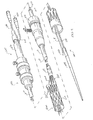
- FIG. 9 illustrates one example of an introducer 600 that may be used to deploy the extension graft 500.
- the introducer 600 may include a first portion 602 configured to remain outside of a patient and a second portion 604 configured for introduction into the patient during use.
- the introducer 600 may include an elongate tubular inner cannula 606 (e.g., a guide wire cannula) extending longitudinally along the length of the introducer.
- a connector (e.g., a Luer Lock fitting) may be positioned at a first end of the inner cannula 606 and/or a tip 608 (e.g., a dilator tip) may be positioned at a second end of the inner cannula opposite the first end.
- the introducer 600 may include an elongate tubular outer cannula 610 (e.g., a pusher cannula) about the inner cannula 606.
- a handle 612 may be positioned at a first end of the outer cannula 610.
- the outer cannula 610 may extend from the first end toward the tip 608 to a second end opposite the first end.
- the introducer 600 may include an elongate tubular sheath 614 about the inner cannula 606 and/or the outer cannula 610.
- a sheath hub 616 may be positioned at a first end of the sheath 614.
- the sheath 614 may extend from the first end toward the tip 608 to a second end opposite the first end.
- the sheath 614 may be longitudinally movable relative to the inner cannula 606 and/or the outer cannula 610.
- the sheath 614 may be retracted toward the handle 612 (e.g., by moving the sheath hub 616) to enable at least partial expansion of the extension graft 500 as further described below.
- the extension graft 500 may be loaded on the introducer 600 such that the inner cannula 606 extends through the lumen 526 of the first extension leg 520 and the lumen 516 of the extension body as shown in FIG. 6 .
- the extension graft 500 may be positioned on the introducer 600 such that the distal end 524 of the first extension leg 520 is directed toward the handle 612 (e.g., toward the first end of the introducer). Additionally, or alternatively, the distal end 534 of the second extension leg 530 may be directed toward the handle 612 (e.g., toward the first end of the introducer 600). Additionally, or alternatively, the proximal end 512 of the extension body 510 may be directed toward the tip 608 (e.g., toward the second end of the introducer 600).
- the introducer 600 may include an elongate tubular auxiliary cannula 618 as shown in FIG. 9 .
- the auxiliary cannula 618 may extend longitudinally along the length of the introducer 600.
- a connector e.g., a Luer Lock fitting
- the auxiliary cannula 618 may extend from the first end toward the tip 608 to a second end opposite the first end.
- the second end of the auxiliary cannula may be positioned adjacent to the tip 608 as shown in FIG. 9 .
- the auxiliary cannula 618 may be positioned within the outer cannula 610 and/or the sheath 614.
- the auxiliary cannula 618 may be positioned within the outer cannula 610 adjacent to the inner cannula 606.
- the auxiliary cannula 618 may extend from the first end through the handle 612 and into the outer cannula 610.
- the auxiliary cannula 618 may extend through the outer cannula 610 and out through the second end of the outer cannula.
- the auxiliary cannula 618 may enter the extension graft 500 through the distal end opening at the distal end 534 of the second extension leg 530 as shown in FIG. 9 .
- the auxiliary cannula 618 may extend through the second extension leg 530 into the extension body 510 and exit the extension graft 500 through the proximal end opening at the proximal end 512 of the extension body.
- the auxiliary cannula 618 may extend away from the extension graft 500 to the second end adjacent to the tip 608 as shown in FIG. 9 .
- An auxiliary guide wire 620 may be disposed within the auxiliary cannula 618.
- the auxiliary guide wire 620 may aid in deploying a branch extension graft within the second extension leg 530 of the extension graft 500 as further described below.
- the auxiliary guide wire 620 may extend from a first end toward the tip 608.
- the auxiliary guide wire 620 may enter the first end of the auxiliary cannula 618 (e.g., through the connector), extend longitudinally within the auxiliary cannula, and exit the second end of the auxiliary cannula. In this manner, the auxiliary guide wire 620 may extend from the first end through the handle 612 and into the outer cannula 610.
- the auxiliary guide wire 620 may extend through the outer cannula 610 and out through the second end of the outer cannula.
- the auxiliary guide wire 620 may enter the extension graft 500 through the distal end opening at the distal end 534 of the second extension leg 530.
- the auxiliary guide wire 620 may extend through the second extension leg 530 into the extension body 510 and exit the extension graft 500 through the proximal end opening at the proximal end 512 of the extension body.
- the auxiliary guide wire 620 may extend away from the extension graft 500 and exit the second end of the auxiliary cannula 618 as shown in FIG. 9 .
- the auxiliary guide wire 620 may be longitudinally movable relative to the auxiliary cannula 620.
- the auxiliary guide wire 620 may be advanced relative to the auxiliary cannula 620 to extend the second end of the auxiliary guide wire farther beyond the second end of the auxiliary cannula. Additionally, or alternatively, the auxiliary guide wire 620 may be retracted relative to the auxiliary cannula 618 to withdraw a portion of the auxiliary guide wire (e.g., the second end of the auxiliary guide wire) into the auxiliary cannula 618.
- the auxiliary cannula 618 and/or the auxiliary guide wire 620 may be preloaded through the extension graft 500 as described herein. In this manner, the auxiliary cannula 618 and/or the auxiliary guide wire 620 may aid in deploying a branch extension graft within the second extension leg 530 as further described below.
- the introducer 600 may be configured as part of a low profile delivery system.
- the auxiliary guide wire 620 may be configured as a 0.035 in wire or a 0.018 in wire (e.g., a wire having a diameter of about 0.035 in or about 0.018 in).
- the auxiliary cannula 618 may be configured as a 4 Fr catheter or a 3 Fr catheter.
- the sheath 614 may have size of less than about 16 Fr, preferably less than about 14 Fr.
- the auxiliary guide wire, the auxiliary cannula, and/or the sheath may have any suitable size.
- FIGS. 10-13 illustrate exemplary steps for deployment of the prosthesis system, including the main graft 400 and the extension graft 500, within the thoracic aorta.
- Deployment of the prosthesis system including the main graft 100 and the extension graft 200 shown in FIGS. 1-3 may be performed in a similar manner.
- the main graft 400 may be deployed within the thoracic aorta using any suitable endovascular technique.
- the main graft 400 may be compressed into a reduced diameter configuration and loaded onto an introducer.
- the main graft 400 may be released from the introducer (e.g., by retraction of a sheath of the introducer and/or manipulation of one or more trigger wires or other retention mechanism) to expand and engage the walls of the thoracic aorta.
- the main graft 400 may extend from the ascending aorta 302, through the thoracic arch 304, and into the descending aorta 306 as shown in FIG. 10 .
- FIG. 10 shows a cutaway view of the main graft 400 so that the tubular extensions disposed within the lumen 410 are visible.
- the extension graft 500 may be deployable within the main graft 400.
- the extension graft 500 may be deployed using any suitable endovascular technique.
- a guide wire 622 may be introduced into the innominate artery 308 (e.g., via the axillary artery or the right carotid artery) and advanced proximally within the innominate artery.
- the guide wire 622 may be advanced proximally through the first fenestration 414a and the first tubular extension 416a of the main graft 400.
- the guide wire 622 may be further advanced proximally within the lumen 410 of the main graft, out through the proximal end opening, and into the descending aorta 302 as shown in FIG. 10 .
- the extension graft 500 may be loaded onto the introducer 600 as described above.
- the introducer 600 may be introduced over the guide wire 622 and advanced proximally through the innominate artery 308.
- the introducer 600 may be advanced further proximally through the first fenestration 414a and the first tubular extension 416a of the main graft 400 such that the tip 608 of the introducer is disposed within the lumen 410 of the main graft 400 as shown in FIG. 10 .
- the auxiliary guide wire 620 may extend proximally beyond the second end of the sheath 614, which may be positioned in the delivery configuration (e.g., abutting the tip 608).
- the second end of the auxiliary guide wire 620 may be exposed outside of the sheath 614.
- the auxiliary guide wire 620 may be snared.
- a snare may be introduced into the thoracic aorta (e.g., via the femoral artery) to snare the second end of the auxiliary guide wire 620.
- the second end of the auxiliary guide wire 620 may be pulled distally through the lumen 410 of the main graft 400 and out through the distal end opening at the distal end 408 of the main graft. This path of the auxiliary guide wire 620 is shown as a solid line in FIG. 10 .
- the second end of the auxiliary guide wire 620 may be pulled out of the patient's body via the femoral artery.
- the auxiliary guide wire 620 may serve as a through wire with both of the first end and the second end of the auxiliary guide wire positioned outside of the patient's body (e.g., the first end via the axillary artery or the right carotid artery and the second end via the femoral artery).
- the auxiliary guide wire 620 may be preloaded in the second extension leg 530 as described above. This may enable deployment of a branch extension graft within the second extension leg 530 as further described below.
- the auxiliary sheath 618 may be retracted over the auxiliary guide wire and removed from the patient's body (e.g., via the axillary artery or the right carotid artery).
- the snare may be introduced into the thoracic aorta via the left subclavian artery 312 to snare the second end of the auxiliary guide wire 620.
- the second end of the auxiliary guide wire 620 may be pulled distally through the second tubular extension 416b and out through the second fenestration 414b of the main graft 400.
- This path of the auxiliary guide wire 620 is shown as a dashed line in FIG. 10 .
- the second end of the auxiliary guide wire 620 may be pulled out of the patient's body via the left subclavian artery.
- the auxiliary guide wire 620 may serve as a through wire with both of the first end and the second end of the auxiliary guide wire positioned outside of the patient's body (e.g., the first end via the axillary artery or the right carotid artery and the second end via the left subclavian artery). This may enable deployment of a branch extension graft within the extension graft 500 as further described below.
- the snare may be introduced into the thoracic aorta via the apex of the left ventricle to snare the second end of the auxiliary guide wire 620.
- the second end of the auxiliary guide wire 620 may be pulled proximally through the proximal end opening of the main graft 400 and out of the patient's body via the left ventricle.
- the auxiliary guide wire 620 may serve as a through wire with both of the first end and the second end of the auxiliary guide wire positioned outside of the patient's body (e.g., the first end via the axillary artery or the right carotid artery and the second end via the left ventricle).
- the extension graft 500 may be deployed within the main graft 400.
- the sheath 614 of the introducer 600 may be at least partially retracted to expose at least a portion of the extension graft 500.
- the sheath 614 may be partially retracted a sufficient distance to expose the second extension leg 530 of the extension graft 500. This may enable a portion of the extension graft 500 (e.g., the extension body 510 and the second extension leg 530) to expand from the radially compressed configuration toward a radially expanded configuration as shown in FIG. 11 .
- the first extension leg 520 may remain compressed within the sheath 614 (e.g., as shown in FIG. 9 ).
- the extension body 510 of the extension graft 500 may extend through the first fenestration 414a of the main graft 400.
- the proximal end 512 of the extension body 510 may be positioned within the lumen 410 of the main graft 400, and the distal end 514 of the extension body may be positioned outside of the lumen of the main graft.
- the extension body 510 of the extension graft 500 may extend at least partially within the first tubular extension 416a of the main graft 400.
- the proximal end 512 of the extension body 510 may be positioned within the lumen 422a of the first tubular extension 416a or proximal of the second end 420a of the first tubular extension.
- the extension body 510 may expand to engage the first tubular extension 416a and/or the sidewall 404 of the main body 402 (e.g., a portion of the sidewall adjacent to the first fenestration 414a).
- a substantially fluid tight seal may be formed between the extension body 510 and the first tubular extension 416a and/or the sidewall 404 to mate the extension graft 500 and the main graft 400 to one another.
- the first extension leg 520 of the extension graft 500 may extend outward away from the main graft 400 and toward the innominate artery 308.
- the first extension leg 520 may have a sufficiently long length to extend into the innominate artery 308 as shown in FIG. 11 .
- the auxiliary guide wire 620 may be disposed between an outer surface of the first extension leg 520 and the wall of the innominate artery 308.
- the first extension leg 520 may remain compressed within the sheath 614 of the introducer 600 as described above. In this manner, a space may be formed between the outer surface of the first extension leg 520 and the wall of the innominate artery 308.
- the auxiliary guide wire 620 may be capable of sliding between the first extension leg 520 and the wall of the innominate artery 308 to retract and remove the auxiliary guide wire from the patient's body as further described below.
- the second extension leg 530 of the extension graft 500 may extend outward away from the main graft 400 and toward the left common carotid artery 310.
- the second extension leg 530 may have a sufficiently short length that the second extension leg does not enter the left common carotid artery 310 as shown in FIG. 11 .
- a branch extension graft may be deployed to couple the second extension leg 530 to the left common carotid artery 310.
- a sheath 700 may be advanced over the auxiliary guide wire 620 as shown in FIG. 12 .
- the sheath 700 may be advanced through the abdominal aorta (e.g., via the femoral artery) as shown in solid lines in FIG. 12 .
- the sheath 700 may be advanced proximally through the distal end 408 of the main graft 400, proximally through the lumen 410, and into the lumen 516 of the extension body 510 through the proximal end 512.
- the sheath 700 may be further advanced into the lumen 536 of the second extension leg 530 and out through the distal end 534. In this manner, the end of the sheath 700 may be positioned adjacent to and/or directed toward the left common carotid artery 310 as shown in FIG. 12 .
- the sheath 700 may be advanced through the left subclavian artery 312 as shown in dashed lines in FIG. 12 .
- the sheath 700 may be advanced proximally through the second fenestration 414b and the second tubular extension 416b of the main graft 400, through the lumen 410, and into the lumen 516 of the extension body 510 through the proximal end 512.
- the sheath 700 may be further advanced into the lumen 536 of the second extension leg 530 and out through the distal end 534. In this manner, the end of the sheath 700 may be positioned adjacent to and/or directed toward the left common carotid artery 310 as shown in FIG. 12 .
- the sheath 700 may be advanced through the left ventricle.
- the sheath 700 may be advanced distally through the proximal end opening into the lumen 410 of the main graft 400, and into the lumen 516 of the extension body 510 through the proximal end 512.
- the sheath 700 may be further advanced into the lumen 536 of the second extension leg 530 and out through the distal end 534. In this manner, the end of the sheath 700 may be positioned adjacent to and/or directed toward the left common carotid artery 310 as shown in FIG. 12 .
- the branch extension graft 240 may be deployed within the extension graft 500 as shown in FIG. 13 .
- the branch extension graft 240 may be deployed via the sheath 700 using any suitable endovascular technique.
- the branch extension graft 240 may be compressed into a reduced diameter configuration and loaded onto an introducer.
- the sheath 700 may be positioned with the end of the sheath adjacent to and/or directed toward the left common carotid artery 310 as shown in FIG. 12 and described above.
- the introducer may be advanced within the sheath 700 and into the left common carotid artery 310.
- the position of the sheath 700 may aid in directing the introducer into the left common carotid artery 310.
- the sheath 700 and the auxiliary guide wire 620 may be retracted and removed from the patient's body.
- the branch extension graft 240 may be released from the introducer (e.g., by retraction of a sheath of the introducer and/or manipulation of one or more trigger wires or other retention mechanism) to expand and engage the extension graft 500 and/or the walls of the left common carotid artery 310.
- the branch extension graft 240 may extend from the second extension leg 530 of the extension graft 500 into the left common carotid artery 310 as shown in FIG. 13 .
- a first portion of the branch extension graft 240 may engage an inner surface of the second extension leg 530, and a second portion of the branch extension graft may engage the wall of the left common carotid artery 310.
- the extension graft 500 may be coupled to the left common carotid artery 310.
- a substantially continuous flow path may be established from the lumen 410 of the main graft 400 to the left common carotid artery 310 (e.g., through the lumen 516 of the extension body 510, the lumen 536 of the second extension leg 530, and the lumen of the branch extension graft 240).
- the main graft 400 may be coupled to the left common carotid artery 310.
- the sheath 614 of the introducer 600 may be further retracted to deploy the first extension leg 520 of the extension graft 500.
- the first extension leg 520 may engage the wall of the innominate artery 308.
- the extension graft 500 may be coupled to the innominate artery 308.
- a substantially continuous flow path may be established from the lumen 410 of the main graft 400 to the innominate artery 308 (e.g., through the lumen 516 of the extension body and the lumen 526 of the first extension leg 520). In this manner, the main graft 400 may be coupled to the innominate artery 308.
- a second branch extension graft 242 may be deployed within the main graft 400 as shown in FIG. 13 .
- the second branch extension graft 242 may be deployed using any suitable endovascular technique.
- the second branch extension graft 242 may be compressed into a reduced diameter configuration and loaded onto an introducer.
- the introducer may be advanced proximally through the left subclavian artery 312, through the second fenestration 414b of the main graft 400, and into the second tubular extension 416b.
- the second branch extension graft 242 may be released from the introducer (e.g., by retraction of a sheath of the introducer and/or manipulation of one or more trigger wires or other retention mechanism) to expand and engage the main graft 400 and/or the walls of the left subclavian artery 312.
- the second branch extension graft 242 may extend outward away from the main graft 400 into the left subclavian artery 312 as shown in FIG. 13 .
- a first portion of the second branch extension graft 242 may engage an inner surface of the second tubular extension 416b, and a second portion of the second branch extension graft may engage the wall of the left subclavian artery 312.
- the main graft 400 may be coupled to the left subclavian artery 312.
- a substantially continuous flow path may be established from the lumen 410 of the main graft 400 to the left subclavian artery 312 (e.g., through the lumen of the second branch extension 242). In this manner, the main graft 400 may be coupled to the left subclavian artery 312.
- the configuration of the extension graft 500 may enable the main graft 400 to be coupled to two branch vessels (e.g., the innominate artery 308 and the left common carotid artery 310) through a single fenestration (e.g., the first fenestration 414a).
- Coupling the main graft 400 to a third branch vessel (e.g., the left subclavian artery 312) as described above may enable the main graft to be coupled to three branch vessels through two fenestrations (e.g., the first fenestration 414a and the second fenestration 414b).
- three branch vessels may be treated with a two-branch device.
- This may reduce the amount of time required to deploy the prosthesis system. Additionally, or alternatively, this may reduce the obstruction of the lumen 410 of the main graft 400 (e.g., because the ends of only the extension body 510 and the second branch extension graft 242 extend into the lumen of the main body) compared to a three branch device (e.g., a device having three fenestrations and three extension grafts extending into the lumen of the main graft).
- a three branch device e.g., a device having three fenestrations and three extension grafts extending into the lumen of the main graft.
- coupling the main graft to each of the three branch vessels may maintain the blood flow to each of the three branch vessels using endovascular techniques without an invasive surgical procedure (e.g., to place an anastomosis between two of the branch vessels). This may reduce procedural and/or recovery times associated with placement of the prosthesis system.
- a patient may have a bovine arch in which the innominate artery and the left common carotid artery share a common origin as opposed to a standard arch in which the innominate artery and the left common carotid artery have separate origins.
- the use of a branched or bifurcated extension graft e.g., the extension graft 200 or the extension graft 400 as described herein may be preferable for use in a patient having a bovine arch.
- the fenestration of the main graft (e.g., the fenestration 114 of the main graft 100 or the first fenestration 414a of the main graft 400) may be generally aligned with the common origin of the innominate artery and the left common carotid artery.
- the first extension leg of the extension graft and the second extension leg of the extension graft may be positioned adjacent to one another in close proximity such that both of the first extension leg and the second extension leg may be directed toward the common origin of the innominate artery and the left common carotid artery.
- FIGS. 14-15 illustrate exemplary steps for deployment of the prosthesis system, including the main graft 400 and the extension graft 500, within the thoracic aorta.
- the main graft 400 may be deployed within the thoracic aorta using any suitable endovascular technique as described above with reference to FIGS. 10-13 .
- the extension graft 500 may be deployable within the main graft 400 using any suitable endovascular technique.
- a guide wire may be introduced into the left subclavian artery 312 and advanced proximally through the second fenestration 414b and the second tubular extension 416b of the main graft 400.
- the guide wire may be further advanced proximally within the lumen 410 of the main graft, out through the proximal end opening, and into the descending aorta 302.
- the extension graft 500 may be loaded onto the introducer 600 as described above.
- the introducer 600 may be introduced over the guide wire and advanced proximally through the left subclavian artery 312.
- the introducer 600 may be advanced further proximally through the second fenestration 414b and the second tubular extension 416b of the main graft 400 such that the tip 608 of the introducer is disposed within the lumen 410 of the main graft 400 as shown in FIG. 14 .
- the second end of the auxiliary guide wire 620 may be exposed outside of the sheath 614.
- the auxiliary guide wire 620 may be snared.
- a snare may be introduced into the innominate artery 308 (e.g., via the axillary artery or the right carotid artery) and advanced into the thoracic aorta to snare the second end of the auxiliary guide wire 620.
- the second end of the auxiliary guide wire 620 may be pulled distally through the first tubular extension 416a and out through the first fenestration 414a of the main graft 400.
- This path of the auxiliary guide wire 620 is shown as a solid line in FIG. 14 .
- the second end of the auxiliary guide wire 620 may be pulled out of the patient's body (e.g., via the axillary artery or the right carotid artery).
- the auxiliary guide wire 620 may serve as a through wire with both of the first end and the second end of the auxiliary guide wire positioned outside of the patient's body (e.g., the first end via the left subclavian artery and the second end via the axillary artery or the right carotid artery).
- the auxiliary sheath 618 if used, may be retracted over the auxiliary guide wire and removed from the patient's body (e.g., via the left subclavian artery 312).
- the snare may be introduced into the thoracic aorta (e.g., via the femoral artery) to snare the second end of the auxiliary guide wire 620.
- the second end of the auxiliary guide wire 620 may be pulled distally through the lumen 410 of the main graft 400 and out through the distal end opening at the distal end 408 of the main graft.
- This path of the auxiliary guide wire 620 is shown as a dashed line in FIG. 14 .
- the second end of the auxiliary guide wire 620 may be pulled out of the patient's body (e.g., via the femoral artery).
- the auxiliary guide wire 620 may serve as a through wire with both of the first end and the second end of the auxiliary guide wire positioned outside of the patient's body (e.g., the first end via the left subclavian artery 312 and the second end via the femoral artery).
- the snare may be introduced into the thoracic aorta via the apex of the left ventricle to snare the second end of the auxiliary guide wire 620.
- the second end of the auxiliary wire 620 may be pulled proximally through the proximal end opening of the main graft 400 and out of the patient's body via the left ventricle.
- the auxiliary guide wire 620 may serve as a through wire with both of the first end and the second end of the auxiliary guide wire positioned outside of the patient's body (e.g., the first end via the left subclavian artery 312 and the second end via the left ventricle).
- the extension graft 500 may be deployed within the main graft 500 as described above.
- the extension body 510 of the extension graft 500 may extend through the second fenestration 414b of the main graft 400 as shown in FIG. 15 .
- the extension body 510 may expand to engage the second tubular extension 416b and/or the sidewall 404 of the main body 402 to mate the extension graft 500 and the main graft 400 to one another.
- the first extension leg 520 of the extension graft 500 may extend outward away from the main graft 400 and toward and/or into the left subclavian artery 312. The first extension leg 520 may remain compressed within the sheath 614 as described above with reference to FIGS. 10-13 .
- the second extension leg 530 of the extension graft 500 may extend outward away from the main graft 400 and toward the left common carotid artery 310 as shown in FIG. 15 .
- the branch extension graft 240 may be used to couple the second extension leg 530 to the left common carotid artery 310 as described above with reference to FIGS. 10-13 (e.g., using the sheath 700 advanced over the auxiliary guide wire 620 and the introducer advanced within the sheath).
- the sheath 614 may be further retracted to enable expansion of the first extension leg 520.
- the first extension leg 520 may engage the wall of the left subclavian artery 312 to couple the extension graft 500 to the left subclavian artery as shown in FIG. 15 .
- a substantially continuous flow path may be established from the lumen 410 of the main graft 400 to the subclavian artery 312 (e.g., through the lumen 516 of the extension body and the lumen 526 of the first extension leg 520) to couple the main graft 400 to the left subclavian artery.
- the second branch extension graft may be deployed within the main graft 400 as described above with reference to FIGS. 10-13 .
- the second branch extension graft may be compressed into a reduced diameter configuration and loaded onto the introducer.
- the introducer may be advanced proximally through the innominate artery 308, through the first fenestration 414a of the main graft 400, and into the first tubular extension 416a.
- the second branch extension graft may extend outward away from the main graft 400 into the innominate artery 308 to couple the main graft 400 to the innominate artery 308.
- the prosthesis system and/or various components thereof may be sized and shaped for placement at a desired position within a patient's anatomy.
- the extension graft e.g., the extension graft 200 and/or the extension graft 500
- the extension graft may have a diameter at the proximal end ranging from about 10 mm to about 16 mm, typically from about 12 mm to about 14 mm, preferably about 13 mm.
- the extension graft may have a diameter at the distal end ranging from about 12 mm to about 26 mm, typically from about 16 mm to about 24 mm.
- the first extension leg and/or the second extension leg may have a diameter ranging from about 5 mm to about 11 mm, typically from about 7 mm to about 9 mm, preferably about 8 mm.
- the extension body may have a length ranging from about 22 mm to about 28 mm, typically from about 24 mm to about 26 mm, preferably about 25 mm.
- the branch ostium may begin about 25 mm distal to the proximal end of the extension body. To that end, the distance between the proximal end of the extension body and the proximal end of the second extension leg may be about 25 mm.
- the support structure of the extension body may include three low profile stents.
- the stents may be disposed on an inner surface of the sidewall of the extension body.
- the support structure of the extension body may include any number stents (e.g., one, two, four, or more), and the stents may be disposed on the inner surface and/or the outer surface of the extension body.
- the fenestration of the main graft e.g., the fenestration 114 of the main graft 100, the first fenestration 114a of the main graft 400, and/or the second fenestration 114b of the main graft 400
- the support structures may include one or more stents having any suitable stent pattern known in the art.
- the stents may be balloon expandable and/or self-expandable.
- One example of a stent pattern is the Z-stent or Gianturco stent design.
- Each Z-stent may include a series of substantially straight segments or struts interconnected by a series of bent segments or bends.
- Alternative stent designs may include, for example, annular stents, helical stents, a woven wire structure, a laser-cut cannula, individual interconnected rings, or another pattern or design.
- the support structures may be made from any suitable material known in the art.
- the support structures may be made from standard medical grade stainless steel and may be soldered using silver standard solder (0 lead/0 tin).
- the support structures may be made from a metallic material selected from any type of stainless steel, silver, platinum, palladium, gold, titanium, tantalum, iridium, tungsten, cobalt, chromium, cobalt-chromium alloy 1058, cobalt-based 35N alloy, nickel-based alloy 625, a molybdenum alloy, a molybdenum alloy including about 0.4% to about 0.8% of lanthanum oxide (La203), a nickel-titanium alloy, or other suitable materials known in the art.
- the stents may be made from Nitinol or other superelastic or shape-memory metal.
- the grafts may be made of any suitable biocompatible graft material known in the art.
- the graft bodies may be made of an expanded polytetrafluoroethylene (ePTFE), polytetrafluoroethylene (PTFE), silicone, polyurethane, polyester, polyamide (nylon), polyethylene, polypropylene, polyaramid, polyacrylonitrile, cellulose, or another flexible biocompatible material.
- the graft bodies may include a bioremodelable material such as reconstituted or naturally-derived collagenous materials such as, for example, collagenous extracellular matrix (ECM) materials such as those including submucosa, renal capsule membrane, dermal collagen, dura mater, pericardium, fascia lata, serosa, peritoneum or basement membrane layers, including liver basement membrane.
- ECM extracellular matrix
- Suitable submucosa materials may include, for example, intestinal submucosa including small intestinal submucosa, stomach submucosa, urinary bladder submucosa, and uterine submucosa.
- Suitable remodelable materials may include SURGISIS® BIODESIGNTM from Cook Medical (Bloomington, Indiana) or the graft prosthesis material described in U.S. Patent No. 6,206,931 to Cook et al. , which is incorporated herein by reference in its entirety.
- the graft materials may include any of the materials described in U.S. Patent No. 7,407,509 to Greenberg et al. or U.S. Patent Application Pub. No. 2009/0171451 by Kuppurathanam et al. , which are incorporated herein by reference in their entirety.
Priority Applications (1)
| Application Number | Priority Date | Filing Date | Title |
|---|---|---|---|
| EP19169046.0A EP3527169B1 (fr) | 2013-03-13 | 2014-03-11 | Système de prothèse endoluminale |
Applications Claiming Priority (1)
| Application Number | Priority Date | Filing Date | Title |
|---|---|---|---|
| US201361779650P | 2013-03-13 | 2013-03-13 |
Related Child Applications (2)
| Application Number | Title | Priority Date | Filing Date |
|---|---|---|---|
| EP19169046.0A Division EP3527169B1 (fr) | 2013-03-13 | 2014-03-11 | Système de prothèse endoluminale |
| EP19169046.0A Division-Into EP3527169B1 (fr) | 2013-03-13 | 2014-03-11 | Système de prothèse endoluminale |
Publications (3)
| Publication Number | Publication Date |
|---|---|
| EP2777610A2 true EP2777610A2 (fr) | 2014-09-17 |
| EP2777610A3 EP2777610A3 (fr) | 2014-10-01 |
| EP2777610B1 EP2777610B1 (fr) | 2019-05-22 |
Family
ID=50272541
Family Applications (2)
| Application Number | Title | Priority Date | Filing Date |
|---|---|---|---|
| EP14275054.6A Active EP2777610B1 (fr) | 2013-03-13 | 2014-03-11 | Système de prothèse endoluminale |
| EP19169046.0A Active EP3527169B1 (fr) | 2013-03-13 | 2014-03-11 | Système de prothèse endoluminale |
Family Applications After (1)
| Application Number | Title | Priority Date | Filing Date |
|---|---|---|---|
| EP19169046.0A Active EP3527169B1 (fr) | 2013-03-13 | 2014-03-11 | Système de prothèse endoluminale |
Country Status (2)
| Country | Link |
|---|---|
| US (1) | US9993330B2 (fr) |
| EP (2) | EP2777610B1 (fr) |
Cited By (3)
| Publication number | Priority date | Publication date | Assignee | Title |
|---|---|---|---|---|
| WO2017114879A1 (fr) * | 2015-12-30 | 2017-07-06 | Jotec Gmbh | Prothèse vasculaire autoexpansible |
| DE102017120819A1 (de) * | 2017-09-08 | 2019-03-14 | Jotec Gmbh | Intraluminales Gefäßprothesensystem |
| CN111658230A (zh) * | 2020-07-09 | 2020-09-15 | 北京裕恒佳科技有限公司 | 人工血管 |
Families Citing this family (20)
| Publication number | Priority date | Publication date | Assignee | Title |
|---|---|---|---|---|
| US9050184B2 (en) * | 2008-08-13 | 2015-06-09 | Allergan, Inc. | Dual plane breast implant |
| US9662232B2 (en) * | 2014-04-11 | 2017-05-30 | Red Vascular Technologies, LLC | Alignment system for multiple branch endografts |
| EP3653177B1 (fr) | 2015-01-11 | 2021-09-01 | Ascyrus Medical, LLC | Dispositif hybride pour une réparation chirurgicale de l'aorte |
| EP3310305B1 (fr) | 2015-06-18 | 2022-05-25 | Ascyrus Medical, LLC | Greffe aortique ramifiée |
| US10130465B2 (en) * | 2016-02-23 | 2018-11-20 | Abbott Cardiovascular Systems Inc. | Bifurcated tubular graft for treating tricuspid regurgitation |
| US10610393B2 (en) | 2016-03-24 | 2020-04-07 | Cook Medical Technologies Llc | Wire retention and release mechanisms |
| EP3600169A4 (fr) | 2017-03-24 | 2020-12-30 | Ascyrus Medical, LLC | Stent auto-expansible multi-spirale et ses procédés de fabrication et d'utilisation |
| US10660770B2 (en) | 2017-07-18 | 2020-05-26 | Cook Medical Technologies Llc | Method of making an internal bidirectional branch |
| DE102018111614A1 (de) * | 2018-05-15 | 2019-11-21 | Jörg Teßarek | Multilumenimplantat |
| US10987207B2 (en) | 2018-06-04 | 2021-04-27 | Cook Medical Technologies Llc | Branched frozen elephant trunk device and method |
| US10905541B2 (en) | 2018-06-04 | 2021-02-02 | Cook Medical Technologies Llc | Branched frozen elephant trunk device and method |
| US11173024B2 (en) | 2018-06-04 | 2021-11-16 | Cook Medical Technologies Llc | Branched frozen elephant trunk device and method |
| CN112118807A (zh) | 2018-06-19 | 2020-12-22 | 美敦力瓦斯科尔勒公司 | 用于多个血管的模块化支架装置和方法 |
| JP2022525788A (ja) | 2019-03-20 | 2022-05-19 | インキュベート メディカル テクノロジーズ、 エルエルシー | 大動脈解離インプラント |
| US11116650B2 (en) | 2019-03-28 | 2021-09-14 | Medtronic Vascular, Inc. | Supra aortic access modular stent assembly and method |
| US11083605B2 (en) | 2019-03-28 | 2021-08-10 | Medtronic Vascular, Inc. | Femoral aortic access modular stent assembly and method |
| US11096775B2 (en) | 2019-07-03 | 2021-08-24 | Medtronic Vascular, Inc. | Single multibranch stent device assembly and method |
| US11826226B2 (en) | 2019-07-31 | 2023-11-28 | Medtronic Vascular, Inc. | Modular multibranch stent assembly and method |
| US11191633B2 (en) | 2019-08-29 | 2021-12-07 | Medtronic Vascular, Inc. | Modular multibranch stent assembly and method |
| US11324582B2 (en) | 2019-09-27 | 2022-05-10 | Medtronic Vascular, Inc. | Docking graft for placement of parallel distally extending grafts assembly and method |
Citations (8)
| Publication number | Priority date | Publication date | Assignee | Title |
|---|---|---|---|---|
| US4902508A (en) | 1988-07-11 | 1990-02-20 | Purdue Research Foundation | Tissue graft composition |
| US5554389A (en) | 1995-04-07 | 1996-09-10 | Purdue Research Foundation | Urinary bladder submucosa derived tissue graft |
| US5993844A (en) | 1997-05-08 | 1999-11-30 | Organogenesis, Inc. | Chemical treatment, without detergents or enzymes, of tissue to form an acellular, collagenous matrix |
| US6099567A (en) | 1996-12-10 | 2000-08-08 | Purdue Research Foundation | Stomach submucosa derived tissue graft |
| US6206931B1 (en) | 1996-08-23 | 2001-03-27 | Cook Incorporated | Graft prosthesis materials |
| US7407509B2 (en) | 2003-01-14 | 2008-08-05 | The Cleveland Clinic Foundation | Branched vessel endoluminal device with fenestration |
| US20090171451A1 (en) | 2007-12-27 | 2009-07-02 | Cook Incorporated | Implantable device having composite weave |
| WO2011100290A1 (fr) | 2010-02-09 | 2011-08-18 | Cook Medical Technologies Llc | Endoprothèse pour aorte thoracique |
Family Cites Families (21)
| Publication number | Priority date | Publication date | Assignee | Title |
|---|---|---|---|---|
| US5676697A (en) * | 1996-07-29 | 1997-10-14 | Cardiovascular Dynamics, Inc. | Two-piece, bifurcated intraluminal graft for repair of aneurysm |
| US5720735A (en) * | 1997-02-12 | 1998-02-24 | Dorros; Gerald | Bifurcated endovascular catheter |
| US6398807B1 (en) * | 2000-01-31 | 2002-06-04 | Scimed Life Systems, Inc. | Braided branching stent, method for treating a lumen therewith, and process for manufacture therefor |
| WO2002030329A2 (fr) * | 2000-10-13 | 2002-04-18 | Rex Medical, L.P. | Stents couverts a branche laterale |
| US7144421B2 (en) | 2003-11-06 | 2006-12-05 | Carpenter Judith T | Endovascular prosthesis, system and method |
| US7674284B2 (en) * | 2004-03-31 | 2010-03-09 | Cook Incorporated | Endoluminal graft |
| ATE389370T1 (de) * | 2004-09-02 | 2008-04-15 | Med Inst Inc | Modulare prothese und verfahren für verzweigte gefässe |
| US7828837B2 (en) | 2005-02-17 | 2010-11-09 | Khoury Medical Devices, LLC. | Vascular endograft |
| US20070106368A1 (en) | 2005-11-07 | 2007-05-10 | Carlos Vonderwalde | Graft-stent assembly |
| US20080027533A1 (en) * | 2006-04-19 | 2008-01-31 | Abbott Laboratories | Dedicated bifurcation stent apparatus and method |
| US8273115B2 (en) * | 2007-04-24 | 2012-09-25 | W. L. Gore & Associates, Inc. | Side branched endoluminal prostheses and methods of delivery thereof |
| US20090062898A1 (en) * | 2007-06-25 | 2009-03-05 | Das Gladwin S | Catheter system for bifurcated coronary vessel |
| US8048147B2 (en) * | 2007-06-27 | 2011-11-01 | Aga Medical Corporation | Branched stent/graft and method of fabrication |
| CA2695679C (fr) * | 2007-08-08 | 2015-12-01 | Cleveland Clinic Foundation | Systeme de greffe de prothese endovasculaire ramifie |
| JP5574123B2 (ja) * | 2008-08-26 | 2014-08-20 | クック メディカル テクノロジーズ エルエルシー | アクセス領域を有する胸部大動脈ステント移植片 |
| CN102470029B (zh) * | 2009-07-31 | 2015-06-17 | 乔泰克公司 | 一体式分叉移植物 |
| EP3735937A1 (fr) * | 2009-11-30 | 2020-11-11 | Endospan Ltd. | Système d'endoprothèse à multiples composants destiné à être implanté dans un vaisseau sanguin avec de multiples ramifications |
| AU2010202544B1 (en) * | 2010-06-18 | 2010-08-26 | Cook Incorporated | Side branch stent graft |
| AU2011200858B1 (en) * | 2011-02-28 | 2012-04-05 | Cook Medical Technologies Llc | Stent graft with valve arrangement |
| WO2013074990A1 (fr) | 2011-11-16 | 2013-05-23 | Bolton Medical, Inc. | Dispositif et procédé pour la réparation de vaisseau branché aortique |
| US9861466B2 (en) | 2012-12-31 | 2018-01-09 | Cook Medical Technologies Llc | Endoluminal prosthesis |
-
2014
- 2014-03-07 US US14/200,513 patent/US9993330B2/en active Active
- 2014-03-11 EP EP14275054.6A patent/EP2777610B1/fr active Active
- 2014-03-11 EP EP19169046.0A patent/EP3527169B1/fr active Active
Patent Citations (8)
| Publication number | Priority date | Publication date | Assignee | Title |
|---|---|---|---|---|
| US4902508A (en) | 1988-07-11 | 1990-02-20 | Purdue Research Foundation | Tissue graft composition |
| US5554389A (en) | 1995-04-07 | 1996-09-10 | Purdue Research Foundation | Urinary bladder submucosa derived tissue graft |
| US6206931B1 (en) | 1996-08-23 | 2001-03-27 | Cook Incorporated | Graft prosthesis materials |
| US6099567A (en) | 1996-12-10 | 2000-08-08 | Purdue Research Foundation | Stomach submucosa derived tissue graft |
| US5993844A (en) | 1997-05-08 | 1999-11-30 | Organogenesis, Inc. | Chemical treatment, without detergents or enzymes, of tissue to form an acellular, collagenous matrix |
| US7407509B2 (en) | 2003-01-14 | 2008-08-05 | The Cleveland Clinic Foundation | Branched vessel endoluminal device with fenestration |
| US20090171451A1 (en) | 2007-12-27 | 2009-07-02 | Cook Incorporated | Implantable device having composite weave |
| WO2011100290A1 (fr) | 2010-02-09 | 2011-08-18 | Cook Medical Technologies Llc | Endoprothèse pour aorte thoracique |
Cited By (7)
| Publication number | Priority date | Publication date | Assignee | Title |
|---|---|---|---|---|
| WO2017114879A1 (fr) * | 2015-12-30 | 2017-07-06 | Jotec Gmbh | Prothèse vasculaire autoexpansible |
| CN108601648A (zh) * | 2015-12-30 | 2018-09-28 | 乔泰克公司 | 自膨胀式血管假体 |
| US10617515B2 (en) | 2015-12-30 | 2020-04-14 | Jotec Gmbh | Self-expanding vascular prosthesis |
| CN108601648B (zh) * | 2015-12-30 | 2020-06-19 | 乔泰克公司 | 自膨胀式血管假体 |
| DE102017120819A1 (de) * | 2017-09-08 | 2019-03-14 | Jotec Gmbh | Intraluminales Gefäßprothesensystem |
| CN111658230A (zh) * | 2020-07-09 | 2020-09-15 | 北京裕恒佳科技有限公司 | 人工血管 |
| CN111658230B (zh) * | 2020-07-09 | 2023-07-18 | 北京裕恒佳科技有限公司 | 人工血管 |
Also Published As
| Publication number | Publication date |
|---|---|
| EP3527169A1 (fr) | 2019-08-21 |
| EP3527169B1 (fr) | 2023-07-19 |
| EP2777610B1 (fr) | 2019-05-22 |
| US20140277348A1 (en) | 2014-09-18 |
| EP2777610A3 (fr) | 2014-10-01 |
| US9993330B2 (en) | 2018-06-12 |
Similar Documents
| Publication | Publication Date | Title |
|---|---|---|
| EP3527169B1 (fr) | Système de prothèse endoluminale | |
| US11607304B2 (en) | Endoluminal prosthesis having multiple branches or fenestrations and methods of deployment | |
| US11547584B2 (en) | Delivery system and method to radially constrict a stent graft | |
| US10166095B2 (en) | Introducer for a side branch device | |
| US10806563B2 (en) | Preloaded wire for endoluminal device | |
| JP5108997B2 (ja) | 胸部大動脈瘤用ステントグラフト | |
| US8480726B2 (en) | Stent graft with valve arrangement | |
| EP2606853B1 (fr) | Remplacement d'arc aortique hybride | |
| EP2985007B1 (fr) | Fil préchargé pour dispositif endoluminal | |
| US10595982B2 (en) | Endoluminal prosthesis | |
| EP2702960B1 (fr) | Prothèse endoluminale et dispositif d'administration | |
| US9763816B2 (en) | Endoluminal prosthesis delivery system and method |
Legal Events
| Date | Code | Title | Description |
|---|---|---|---|
| PUAL | Search report despatched |
Free format text: ORIGINAL CODE: 0009013 |
|
| 17P | Request for examination filed |
Effective date: 20140311 |
|
| AK | Designated contracting states |
Kind code of ref document: A2 Designated state(s): AL AT BE BG CH CY CZ DE DK EE ES FI FR GB GR HR HU IE IS IT LI LT LU LV MC MK MT NL NO PL PT RO RS SE SI SK SM TR |
|
| AX | Request for extension of the european patent |
Extension state: BA ME |
|
| PUAI | Public reference made under article 153(3) epc to a published international application that has entered the european phase |
Free format text: ORIGINAL CODE: 0009012 |
|
| AK | Designated contracting states |
Kind code of ref document: A3 Designated state(s): AL AT BE BG CH CY CZ DE DK EE ES FI FR GB GR HR HU IE IS IT LI LT LU LV MC MK MT NL NO PL PT RO RS SE SI SK SM TR |
|
| AX | Request for extension of the european patent |
Extension state: BA ME |
|
| RIC1 | Information provided on ipc code assigned before grant |
Ipc: A61F 2/06 20130101ALI20140826BHEP Ipc: A61F 2/07 20130101AFI20140826BHEP |
|
| R17P | Request for examination filed (corrected) |
Effective date: 20150327 |
|
| RBV | Designated contracting states (corrected) |
Designated state(s): AL AT BE BG CH CY CZ DE DK EE ES FI FR GB GR HR HU IE IS IT LI LT LU LV MC MK MT NL NO PL PT RO RS SE SI SK SM TR |
|
| 17Q | First examination report despatched |
Effective date: 20160908 |
|
| STAA | Information on the status of an ep patent application or granted ep patent |
Free format text: STATUS: EXAMINATION IS IN PROGRESS |
|
| RIC1 | Information provided on ipc code assigned before grant |
Ipc: A61F 2/07 20130101AFI20181003BHEP Ipc: A61F 2/06 20130101ALI20181003BHEP Ipc: A61F 2/954 20130101ALI20181003BHEP |
|
| GRAP | Despatch of communication of intention to grant a patent |
Free format text: ORIGINAL CODE: EPIDOSNIGR1 |
|
| STAA | Information on the status of an ep patent application or granted ep patent |
Free format text: STATUS: GRANT OF PATENT IS INTENDED |
|
| INTG | Intention to grant announced |
Effective date: 20181128 |
|
| RIN1 | Information on inventor provided before grant (corrected) |
Inventor name: ROEDER, BLAYNE A. |
|
| GRAS | Grant fee paid |
Free format text: ORIGINAL CODE: EPIDOSNIGR3 |
|
| GRAA | (expected) grant |
Free format text: ORIGINAL CODE: 0009210 |
|
| STAA | Information on the status of an ep patent application or granted ep patent |
Free format text: STATUS: THE PATENT HAS BEEN GRANTED |
|
| AK | Designated contracting states |
Kind code of ref document: B1 Designated state(s): AL AT BE BG CH CY CZ DE DK EE ES FI FR GB GR HR HU IE IS IT LI LT LU LV MC MK MT NL NO PL PT RO RS SE SI SK SM TR |
|
| REG | Reference to a national code |
Ref country code: GB Ref legal event code: FG4D |
|
| REG | Reference to a national code |
Ref country code: CH Ref legal event code: EP |
|
| REG | Reference to a national code |
Ref country code: IE Ref legal event code: FG4D |
|
| REG | Reference to a national code |
Ref country code: DE Ref legal event code: R096 Ref document number: 602014047150 Country of ref document: DE |
|
| REG | Reference to a national code |
Ref country code: AT Ref legal event code: REF Ref document number: 1135166 Country of ref document: AT Kind code of ref document: T Effective date: 20190615 |
|
| REG | Reference to a national code |
Ref country code: NL Ref legal event code: MP Effective date: 20190522 |
|
| REG | Reference to a national code |
Ref country code: LT Ref legal event code: MG4D |
|
| PG25 | Lapsed in a contracting state [announced via postgrant information from national office to epo] |
Ref country code: AL Free format text: LAPSE BECAUSE OF FAILURE TO SUBMIT A TRANSLATION OF THE DESCRIPTION OR TO PAY THE FEE WITHIN THE PRESCRIBED TIME-LIMIT Effective date: 20190522 Ref country code: PT Free format text: LAPSE BECAUSE OF FAILURE TO SUBMIT A TRANSLATION OF THE DESCRIPTION OR TO PAY THE FEE WITHIN THE PRESCRIBED TIME-LIMIT Effective date: 20190922 Ref country code: SE Free format text: LAPSE BECAUSE OF FAILURE TO SUBMIT A TRANSLATION OF THE DESCRIPTION OR TO PAY THE FEE WITHIN THE PRESCRIBED TIME-LIMIT Effective date: 20190522 Ref country code: FI Free format text: LAPSE BECAUSE OF FAILURE TO SUBMIT A TRANSLATION OF THE DESCRIPTION OR TO PAY THE FEE WITHIN THE PRESCRIBED TIME-LIMIT Effective date: 20190522 Ref country code: NO Free format text: LAPSE BECAUSE OF FAILURE TO SUBMIT A TRANSLATION OF THE DESCRIPTION OR TO PAY THE FEE WITHIN THE PRESCRIBED TIME-LIMIT Effective date: 20190822 Ref country code: HR Free format text: LAPSE BECAUSE OF FAILURE TO SUBMIT A TRANSLATION OF THE DESCRIPTION OR TO PAY THE FEE WITHIN THE PRESCRIBED TIME-LIMIT Effective date: 20190522 Ref country code: NL Free format text: LAPSE BECAUSE OF FAILURE TO SUBMIT A TRANSLATION OF THE DESCRIPTION OR TO PAY THE FEE WITHIN THE PRESCRIBED TIME-LIMIT Effective date: 20190522 Ref country code: ES Free format text: LAPSE BECAUSE OF FAILURE TO SUBMIT A TRANSLATION OF THE DESCRIPTION OR TO PAY THE FEE WITHIN THE PRESCRIBED TIME-LIMIT Effective date: 20190522 Ref country code: LT Free format text: LAPSE BECAUSE OF FAILURE TO SUBMIT A TRANSLATION OF THE DESCRIPTION OR TO PAY THE FEE WITHIN THE PRESCRIBED TIME-LIMIT Effective date: 20190522 |
|
| PG25 | Lapsed in a contracting state [announced via postgrant information from national office to epo] |
Ref country code: LV Free format text: LAPSE BECAUSE OF FAILURE TO SUBMIT A TRANSLATION OF THE DESCRIPTION OR TO PAY THE FEE WITHIN THE PRESCRIBED TIME-LIMIT Effective date: 20190522 Ref country code: RS Free format text: LAPSE BECAUSE OF FAILURE TO SUBMIT A TRANSLATION OF THE DESCRIPTION OR TO PAY THE FEE WITHIN THE PRESCRIBED TIME-LIMIT Effective date: 20190522 Ref country code: BG Free format text: LAPSE BECAUSE OF FAILURE TO SUBMIT A TRANSLATION OF THE DESCRIPTION OR TO PAY THE FEE WITHIN THE PRESCRIBED TIME-LIMIT Effective date: 20190822 Ref country code: GR Free format text: LAPSE BECAUSE OF FAILURE TO SUBMIT A TRANSLATION OF THE DESCRIPTION OR TO PAY THE FEE WITHIN THE PRESCRIBED TIME-LIMIT Effective date: 20190823 |
|
| REG | Reference to a national code |
Ref country code: AT Ref legal event code: MK05 Ref document number: 1135166 Country of ref document: AT Kind code of ref document: T Effective date: 20190522 |
|
| PG25 | Lapsed in a contracting state [announced via postgrant information from national office to epo] |
Ref country code: CZ Free format text: LAPSE BECAUSE OF FAILURE TO SUBMIT A TRANSLATION OF THE DESCRIPTION OR TO PAY THE FEE WITHIN THE PRESCRIBED TIME-LIMIT Effective date: 20190522 Ref country code: DK Free format text: LAPSE BECAUSE OF FAILURE TO SUBMIT A TRANSLATION OF THE DESCRIPTION OR TO PAY THE FEE WITHIN THE PRESCRIBED TIME-LIMIT Effective date: 20190522 Ref country code: AT Free format text: LAPSE BECAUSE OF FAILURE TO SUBMIT A TRANSLATION OF THE DESCRIPTION OR TO PAY THE FEE WITHIN THE PRESCRIBED TIME-LIMIT Effective date: 20190522 Ref country code: EE Free format text: LAPSE BECAUSE OF FAILURE TO SUBMIT A TRANSLATION OF THE DESCRIPTION OR TO PAY THE FEE WITHIN THE PRESCRIBED TIME-LIMIT Effective date: 20190522 Ref country code: SK Free format text: LAPSE BECAUSE OF FAILURE TO SUBMIT A TRANSLATION OF THE DESCRIPTION OR TO PAY THE FEE WITHIN THE PRESCRIBED TIME-LIMIT Effective date: 20190522 Ref country code: RO Free format text: LAPSE BECAUSE OF FAILURE TO SUBMIT A TRANSLATION OF THE DESCRIPTION OR TO PAY THE FEE WITHIN THE PRESCRIBED TIME-LIMIT Effective date: 20190522 |
|
| REG | Reference to a national code |
Ref country code: DE Ref legal event code: R097 Ref document number: 602014047150 Country of ref document: DE |
|
| PG25 | Lapsed in a contracting state [announced via postgrant information from national office to epo] |
Ref country code: IT Free format text: LAPSE BECAUSE OF FAILURE TO SUBMIT A TRANSLATION OF THE DESCRIPTION OR TO PAY THE FEE WITHIN THE PRESCRIBED TIME-LIMIT Effective date: 20190522 Ref country code: SM Free format text: LAPSE BECAUSE OF FAILURE TO SUBMIT A TRANSLATION OF THE DESCRIPTION OR TO PAY THE FEE WITHIN THE PRESCRIBED TIME-LIMIT Effective date: 20190522 |
|
| PLBE | No opposition filed within time limit |
Free format text: ORIGINAL CODE: 0009261 |
|
| STAA | Information on the status of an ep patent application or granted ep patent |
Free format text: STATUS: NO OPPOSITION FILED WITHIN TIME LIMIT |
|
| PG25 | Lapsed in a contracting state [announced via postgrant information from national office to epo] |
Ref country code: TR Free format text: LAPSE BECAUSE OF FAILURE TO SUBMIT A TRANSLATION OF THE DESCRIPTION OR TO PAY THE FEE WITHIN THE PRESCRIBED TIME-LIMIT Effective date: 20190522 |
|
| 26N | No opposition filed |
Effective date: 20200225 |
|
| PG25 | Lapsed in a contracting state [announced via postgrant information from national office to epo] |
Ref country code: PL Free format text: LAPSE BECAUSE OF FAILURE TO SUBMIT A TRANSLATION OF THE DESCRIPTION OR TO PAY THE FEE WITHIN THE PRESCRIBED TIME-LIMIT Effective date: 20190522 |
|
| PG25 | Lapsed in a contracting state [announced via postgrant information from national office to epo] |
Ref country code: SI Free format text: LAPSE BECAUSE OF FAILURE TO SUBMIT A TRANSLATION OF THE DESCRIPTION OR TO PAY THE FEE WITHIN THE PRESCRIBED TIME-LIMIT Effective date: 20190522 |
|
| PG25 | Lapsed in a contracting state [announced via postgrant information from national office to epo] |
Ref country code: MC Free format text: LAPSE BECAUSE OF FAILURE TO SUBMIT A TRANSLATION OF THE DESCRIPTION OR TO PAY THE FEE WITHIN THE PRESCRIBED TIME-LIMIT Effective date: 20190522 |
|
| REG | Reference to a national code |
Ref country code: CH Ref legal event code: PL |
|
| REG | Reference to a national code |
Ref country code: BE Ref legal event code: MM Effective date: 20200331 |
|
| PG25 | Lapsed in a contracting state [announced via postgrant information from national office to epo] |
Ref country code: LU Free format text: LAPSE BECAUSE OF NON-PAYMENT OF DUE FEES Effective date: 20200311 |
|
| PG25 | Lapsed in a contracting state [announced via postgrant information from national office to epo] |
Ref country code: LI Free format text: LAPSE BECAUSE OF NON-PAYMENT OF DUE FEES Effective date: 20200331 Ref country code: CH Free format text: LAPSE BECAUSE OF NON-PAYMENT OF DUE FEES Effective date: 20200331 Ref country code: FR Free format text: LAPSE BECAUSE OF NON-PAYMENT OF DUE FEES Effective date: 20200331 |
|
| PG25 | Lapsed in a contracting state [announced via postgrant information from national office to epo] |
Ref country code: BE Free format text: LAPSE BECAUSE OF NON-PAYMENT OF DUE FEES Effective date: 20200331 |
|
| PG25 | Lapsed in a contracting state [announced via postgrant information from national office to epo] |
Ref country code: MT Free format text: LAPSE BECAUSE OF FAILURE TO SUBMIT A TRANSLATION OF THE DESCRIPTION OR TO PAY THE FEE WITHIN THE PRESCRIBED TIME-LIMIT Effective date: 20190522 Ref country code: CY Free format text: LAPSE BECAUSE OF FAILURE TO SUBMIT A TRANSLATION OF THE DESCRIPTION OR TO PAY THE FEE WITHIN THE PRESCRIBED TIME-LIMIT Effective date: 20190522 |
|
| PG25 | Lapsed in a contracting state [announced via postgrant information from national office to epo] |
Ref country code: MK Free format text: LAPSE BECAUSE OF FAILURE TO SUBMIT A TRANSLATION OF THE DESCRIPTION OR TO PAY THE FEE WITHIN THE PRESCRIBED TIME-LIMIT Effective date: 20190522 Ref country code: IS Free format text: LAPSE BECAUSE OF FAILURE TO SUBMIT A TRANSLATION OF THE DESCRIPTION OR TO PAY THE FEE WITHIN THE PRESCRIBED TIME-LIMIT Effective date: 20190922 |
|
| PGFP | Annual fee paid to national office [announced via postgrant information from national office to epo] |
Ref country code: IE Payment date: 20230223 Year of fee payment: 10 |
|
| PGFP | Annual fee paid to national office [announced via postgrant information from national office to epo] |
Ref country code: GB Payment date: 20230208 Year of fee payment: 10 Ref country code: DE Payment date: 20230210 Year of fee payment: 10 |
|
| P01 | Opt-out of the competence of the unified patent court (upc) registered |
Effective date: 20230602 |