EP2777555A1 - Drill guide assembly - Google Patents
Drill guide assembly Download PDFInfo
- Publication number
- EP2777555A1 EP2777555A1 EP14157965.6A EP14157965A EP2777555A1 EP 2777555 A1 EP2777555 A1 EP 2777555A1 EP 14157965 A EP14157965 A EP 14157965A EP 2777555 A1 EP2777555 A1 EP 2777555A1
- Authority
- EP
- European Patent Office
- Prior art keywords
- housing
- assembly
- recited
- drill sleeve
- alignment bar
- Prior art date
- Legal status (The legal status is an assumption and is not a legal conclusion. Google has not performed a legal analysis and makes no representation as to the accuracy of the status listed.)
- Granted
Links
Images


Classifications
-
- A—HUMAN NECESSITIES
- A61—MEDICAL OR VETERINARY SCIENCE; HYGIENE
- A61B—DIAGNOSIS; SURGERY; IDENTIFICATION
- A61B17/00—Surgical instruments, devices or methods
- A61B17/16—Instruments for performing osteoclasis; Drills or chisels for bones; Trepans
- A61B17/17—Guides or aligning means for drills, mills, pins or wires
- A61B17/1739—Guides or aligning means for drills, mills, pins or wires specially adapted for particular parts of the body
- A61B17/1742—Guides or aligning means for drills, mills, pins or wires specially adapted for particular parts of the body for the hip
- A61B17/175—Guides or aligning means for drills, mills, pins or wires specially adapted for particular parts of the body for the hip for preparing the femur for hip prosthesis insertion
-
- A—HUMAN NECESSITIES
- A61—MEDICAL OR VETERINARY SCIENCE; HYGIENE
- A61B—DIAGNOSIS; SURGERY; IDENTIFICATION
- A61B17/00—Surgical instruments, devices or methods
- A61B17/16—Instruments for performing osteoclasis; Drills or chisels for bones; Trepans
- A61B17/1662—Instruments for performing osteoclasis; Drills or chisels for bones; Trepans for particular parts of the body
- A61B17/1664—Instruments for performing osteoclasis; Drills or chisels for bones; Trepans for particular parts of the body for the hip
- A61B17/1668—Instruments for performing osteoclasis; Drills or chisels for bones; Trepans for particular parts of the body for the hip for the upper femur
-
- A—HUMAN NECESSITIES
- A61—MEDICAL OR VETERINARY SCIENCE; HYGIENE
- A61B—DIAGNOSIS; SURGERY; IDENTIFICATION
- A61B17/00—Surgical instruments, devices or methods
- A61B17/16—Instruments for performing osteoclasis; Drills or chisels for bones; Trepans
- A61B17/17—Guides or aligning means for drills, mills, pins or wires
- A61B17/1714—Guides or aligning means for drills, mills, pins or wires for applying tendons or ligaments
-
- A—HUMAN NECESSITIES
- A61—MEDICAL OR VETERINARY SCIENCE; HYGIENE
- A61B—DIAGNOSIS; SURGERY; IDENTIFICATION
- A61B17/00—Surgical instruments, devices or methods
- A61B17/16—Instruments for performing osteoclasis; Drills or chisels for bones; Trepans
- A61B17/17—Guides or aligning means for drills, mills, pins or wires
- A61B17/1721—Guides or aligning means for drills, mills, pins or wires for applying pins along or parallel to the axis of the femoral neck
-
- A—HUMAN NECESSITIES
- A61—MEDICAL OR VETERINARY SCIENCE; HYGIENE
- A61B—DIAGNOSIS; SURGERY; IDENTIFICATION
- A61B17/00—Surgical instruments, devices or methods
- A61B17/16—Instruments for performing osteoclasis; Drills or chisels for bones; Trepans
- A61B17/17—Guides or aligning means for drills, mills, pins or wires
- A61B17/1739—Guides or aligning means for drills, mills, pins or wires specially adapted for particular parts of the body
- A61B17/1742—Guides or aligning means for drills, mills, pins or wires specially adapted for particular parts of the body for the hip
-
- A—HUMAN NECESSITIES
- A61—MEDICAL OR VETERINARY SCIENCE; HYGIENE
- A61B—DIAGNOSIS; SURGERY; IDENTIFICATION
- A61B17/00—Surgical instruments, devices or methods
- A61B17/16—Instruments for performing osteoclasis; Drills or chisels for bones; Trepans
- A61B17/1697—Instruments for performing osteoclasis; Drills or chisels for bones; Trepans specially adapted for wire insertion
-
- A—HUMAN NECESSITIES
- A61—MEDICAL OR VETERINARY SCIENCE; HYGIENE
- A61B—DIAGNOSIS; SURGERY; IDENTIFICATION
- A61B17/00—Surgical instruments, devices or methods
- A61B17/16—Instruments for performing osteoclasis; Drills or chisels for bones; Trepans
- A61B17/17—Guides or aligning means for drills, mills, pins or wires
- A61B17/1703—Guides or aligning means for drills, mills, pins or wires using imaging means, e.g. by X-rays
Definitions
- This disclosure relates to orthopedic surgical instrumentation, and more particularly to a drill guide assembly for performing arthroscopic procedures.
- Arthroscopic procedures are commonly performed to diagnose and treat problems in joints. For example, ligament reconstruction, bone resurfacing and joint replacement may all be performed using arthroscopic reconstruction procedures that typically require a surgeon to work through a series of portals. In some joints, such as the hip joint, it may be difficult to efficiently and accurately position the surgical instrumentation needed to perform a specific procedure through the arthroscopic portals.
- a drill guide assembly includes, among other things, a drill sleeve and an alignment bar spaced from the drill sleeve. A positioning of the drill sleeve is linked to a positioning of the alignment bar.
- the alignment bar extends in parallel with the drill sleeve.
- the drill guide assembly includes a first housing and a second housing spaced from the first housing.
- the drill sleeve is received through the first housing and the alignment bar is received through the second housing.
- a handle extends from at least one of the first housing and the second housing.
- At least one of the first housing and the second housing includes a mechanism that is actuable to lock a positioning of the drill sleeve or the alignment bar relative to the first housing or the second housing.
- At least one guide pin connects between the first housing and the second housing.
- the drill sleeve is received through a bore formed in the first housing.
- the bore is transverse to an opening formed in the first housing for receiving a guide pin that connects between the first housing and the second housing.
- the alignment bar includes a radiopaque member, and the radiopaque member is visible in a fluoroscopic image of a joint for estimating the positioning of the drill sleeve.
- an instrument is insertable through the drill sleeve to form an opening in a bone.
- a surgical method includes generating a fluoroscopic image of a joint, positioning an alignment bar of a drill guide assembly at a desired location relative to the joint, visualizing the alignment bar in the fluoroscopic image and selecting a positioning of an instrument to be inserted into the joint based on the positioning of the alignment bar in the fluoroscopic image.
- the step of generating the fluoroscopic image is performed before the step of positioning the alignment bar.
- the step of positioning the alignment bar includes adjusting a distance between a first housing and a second housing of the drill guide assembly.
- the alignment bar is positioned exterior to the joint during the step of positioning.
- the method includes drilling a tunnel in a bone of the joint after the step of selecting and passing a graft through the tunnel.
- a method for reconstructing a ligamentum teres of a hip joint includes, among other things, positioning a drill guide assembly relative to a hip joint, visualizing an alignment bar of the drill guide assembly in an image of the hip joint, adjusting a positioning of a drill sleeve of the drill guide assembly by referencing a positioning of the alignment bar in the image, and reaming a tunnel into a bone of the hip joint through the drill sleeve at the adjusted position.
- the method includes passing a graft at least partially through the tunnel and fixating the graft with at least one fixation device to reconstruct the ligamentum teres.
- the method includes the step of fluoroscopically imaging the hip joint prior to the step of positioning the drill guide assembly.
- the method includes the step of inserting an instrument through the drill sleeve of the drill guide assembly prior to the step of reaming the tunnel.
- the step of positioning includes aligning the alignment bar in parallel with the drill sleeve.
- this disclosure relates to a surgical device, such as a drill guide assembly, that can be used in various orthopedic procedures to efficiently and accurately position other surgical instrumentation relative to bone.
- the drill guide assembly of this disclosure is used to prepare a hip joint for reconstructing the ligamentum teres.
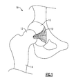
- the ligamentum teres 10 connects a femoral head 12 of a femur 14 to an acetabulum 16 of a hip joint 18.
- this disclosure could extend to other orthopedic procedures, including but not limited to, bone resurfacing procedures, joint replacement procedures, or other ligament reconstruction procedures.
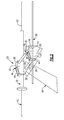
- FIG. 2 illustrates an exemplary drill guide assembly 20.
- the drill guide assembly 20 is an orthopedic surgical device that may be part of a surgical instrumentation set for preparing a joint for an arthroscopic procedure, such as ligament reconstruction.
- the drill guide assembly 20 includes a first housing 22, a second housing 24 and one or more guide pins 26 that connect between the first housing 22 and the second housing 24.
- the drill guide assembly 20 includes two guide pins 26.
- a greater or fewer number of pins may extend between the first and second housings 22, 24 within the scope of this disclosure.
- the guide pins 26 may be received in openings 28 that extend through each of the first housing 22 and the second housing 24.
- the first housing 22 and the second housing 24 may be positioned in a parallel relationship relative to one another.
- the first housing 22 and the second housing 24 are movable along the guide pins 26 to adjust a distance D that extends between the first housing 22 and the second housing 24.
- the distance D that extends between the first housing 22 and the second housing 24 may depend on the size of the joint the drill guide assembly 20 is to be positioned relative to, among other surgical criteria.
- the drill guide assembly 20 may additionally include a locking pin 30 that adjustably locks a positioning of the first and second housings 22, 24 relative to one another.
- the locking pin 30 could be disposed on the first housing 22, the second housing 24, or both, and can be turned to lock/unlock movement of the first housing 22 and/or the second housing 24 along the guide pins 26.
- a drill sleeve 32 is received through a bore 36 of the first housing 22 and an alignment bar 38 is received through a bore 40 of the second housing 24.
- the bores 36, 40 are transverse to the openings 28, in this embodiment.
- the drill sleeve 32 and the alignment bar 38 are generally parallel to one another such that the alignment bar 38 can be used to accurately position the drill sleeve 32. In other words, the positioning of the drill sleeve 32 is linked to the positioning of the alignment bar 38.
- the alignment bar 38 is a radiopaque member and can include a metallic rod or other structure that is visible in fluoroscopic images. Therefore, the alignment bar 38 can be relied on to estimate the positioning of an instrument 42 inserted through the drill sleeve 32 and into the joint space.
- the instrument 42 such as a guide pin or drill, can be inserted through the drill sleeve 32 to create a bone tunnel that may be needed to prepare a joint for an arthroscopic procedure.
- the drill sleeve 32 and the alignment bar 38 are axially adjustable relative to the first housing 22 and the second housing 24, respectively.
- Each housing 22, 24 includes a mechanism 44 that can be actuated in an inward pivoting motion M to permit or prevent movement of the drill sleeve 32 and alignment bar 38 within the bores 36, 40.
- a handle 46 may extend from at least one of the first housing 22 and the second housing 24 (or both).
- the handle 46 allows a surgeon to grip the drill guide assembly 20 when positioning it relative to a joint or bone.
- the handle 46 extends from the first housing 22 at a transverse angle relative to the drill sleeve 32.
- the size, shape and other design characteristics of the handle 46 are not intended to limit this disclosure.
- Figures 3, 4 , 5A, 5B , 6, 7 and 8 schematically illustrate an exemplary method for performing an arthroscopic procedure using the drill guide assembly 20 described above and illustrated in Figure 2 .
- the exemplary drill guide assembly 20 efficiently and accurately positions surgical instrumentation needed to perform a specific arthroscopic procedure.
- the method includes the reconstruction of a ligamentum teres of the hip joint.
- this disclosure is not limited to the reconstruction of the ligamentum teres.
- the method could include greater or fewer method steps and these steps could be performed in a different order than described herein within the scope of this disclosure.
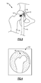
- the method begins by preparing the hip joint 18 for the arthroscopic surgical procedure. If necessary, the entire ligamentum teres 10 may be resected using a resection device 45 (shown schematically), such as a shaver. Additional procedures may also be performed to prepare the hip joint 18 for the arthroscopic procedure, such as preparing a bleeding bone bed with a rasp, etc.
- a resection device 45 shown schematically
- Additional procedures may also be performed to prepare the hip joint 18 for the arthroscopic procedure, such as preparing a bleeding bone bed with a rasp, etc.
- Figure 4 illustrates a fluoroscopic image 50 of the hip joint 18 that can be generated either before or after the step of preparing the hip joint 18 by resecting the ligamentum teres 10.
- the fluoroscopic image 50 provides real-time, moving images of the internal structure of a patient through the use of a fluoroscope.
- a person of ordinary skill in the art would understand how to generate a fluoroscopic image of a joint using a fluoroscope.
- the drill guide assembly 20 may next be positioned relative to the hip joint 18.
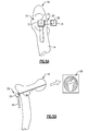
- Figure 5A illustrates a lateral view of the femur 14, and
- Figure 5B illustrates an anterior/posterior view of the hip joint 18.
- the first housing 22 of the drill guide assembly 20 may be aligned with the center of a femoral neck 15 of the femur 14, and the alignment bar 38 of the drill guide assembly 20 may be positioned outside the skin of the patient in the vicinity of the hip joint 18 (i.e., exterior to the joint).
- the distance D (see Figure 2 ) between the first housing 22 and the second housing 24 can be adjusted to position the alignment bar 38 at a desired location relative to the hip joint 18.
- the alignment bar 38 is visible in the fluoroscopic image 50 due to its radiopaque nature. Because the alignment bar 38 is maintained in parallel with the drill sleeve 32, the alignment bar 38 shows the lateral to medial trajectory of the drill sleeve 32. The positioning of the alignment bar 38 can be adjusted by adjusting the distance D as well as axially moving the alignment bar 38 and drill sleeve 32 relative to the housings 22, 24 by actuating the mechanisms 44 (see Figure 2 ).
- an instrument 42 such as a guide pin, can be inserted through the drill sleeve 32 into the femur 14 (see Figure 6 ).
- the instrument 42 is driven from the lateral aspect of the femur 14 and through a femoral head 12 of the femur 14 until the instrument exits through the femoral head 12.
- the ideal exiting location of the instrument 42 is the native location of the ligamentum teres 10 (i.e., the location where the ligamentum teres connects to the femoral head 12).
- the drill guide assembly 20 may be removed once the surgeon is satisfied with the exiting location of the instrument 42.
- a cannulated drill bit 58 is next placed over the instrument 42 to ream a bone tunnel 60 into the femur 14. This is illustrated in Figure 7 .
- the size of the instrument 42 and the cannulated drill bit 58 may vary depending upon the size of the patient and the size of the graft that is to be passed, among other criteria.
- the cannulated drill bit 58 and the instrument 42 may be removed from the hip joint 18.
- the acetabulum 16 of the hip joint 18 may then be prepared for acetabular fixation through a variety of arthroscopic portals (not shown).
- a graft 62 can be passed through the bone tunnel 60 to complete the ligamentum teres reconstruction.
- the hip joint 18 may need abducted prior to passing the graft 60.
- the graft 62 may be any type of graft, including an artificial or natural graft.
- Acetabular fixation and femoral fixation of the graft 62 may be achieved using a fixation device 64, such as a barbed post, a screw, or a suspensory fixation device.
- Arthrex's Retrobutton® and ACL Tightrope® are non-limiting examples of fixation devices that may be used to achieve graft fixation.
- One fixation location of the acetabular component of the reconstruction is on the inner lamina of the pelvis, whereas the femoral fixation can be located at the lateral aspect of the femur 14.
Landscapes
- Health & Medical Sciences (AREA)
- Surgery (AREA)
- Life Sciences & Earth Sciences (AREA)
- Orthopedic Medicine & Surgery (AREA)
- Engineering & Computer Science (AREA)
- General Health & Medical Sciences (AREA)
- Oral & Maxillofacial Surgery (AREA)
- Dentistry (AREA)
- Veterinary Medicine (AREA)
- Biomedical Technology (AREA)
- Heart & Thoracic Surgery (AREA)
- Medical Informatics (AREA)
- Molecular Biology (AREA)
- Animal Behavior & Ethology (AREA)
- Nuclear Medicine, Radiotherapy & Molecular Imaging (AREA)
- Public Health (AREA)
- Rheumatology (AREA)
- Surgical Instruments (AREA)
- Prostheses (AREA)
Abstract
Description
- This disclosure relates to orthopedic surgical instrumentation, and more particularly to a drill guide assembly for performing arthroscopic procedures.
- Arthroscopic procedures are commonly performed to diagnose and treat problems in joints. For example, ligament reconstruction, bone resurfacing and joint replacement may all be performed using arthroscopic reconstruction procedures that typically require a surgeon to work through a series of portals. In some joints, such as the hip joint, it may be difficult to efficiently and accurately position the surgical instrumentation needed to perform a specific procedure through the arthroscopic portals.
- A drill guide assembly according to an exemplary aspect of the present disclosure includes, among other things, a drill sleeve and an alignment bar spaced from the drill sleeve. A positioning of the drill sleeve is linked to a positioning of the alignment bar.
- In a further non-limiting embodiment of the foregoing assembly, the alignment bar extends in parallel with the drill sleeve.
- In a further non-limiting embodiment of either of the foregoing assemblies, the drill guide assembly includes a first housing and a second housing spaced from the first housing. The drill sleeve is received through the first housing and the alignment bar is received through the second housing.
- In a further non-limiting embodiment of any of the foregoing assemblies, a handle extends from at least one of the first housing and the second housing.
- In a further non-limiting embodiment of any of the foregoing assemblies, at least one of the first housing and the second housing includes a mechanism that is actuable to lock a positioning of the drill sleeve or the alignment bar relative to the first housing or the second housing.
- In a further non-limiting embodiment of any of the foregoing assemblies, at least one guide pin connects between the first housing and the second housing.
- In a further non-limiting embodiment of any of the foregoing assemblies, the drill sleeve is received through a bore formed in the first housing.
- In a further non-limiting embodiment of any of the foregoing assemblies, the bore is transverse to an opening formed in the first housing for receiving a guide pin that connects between the first housing and the second housing.
- In a further non-limiting embodiment of any of the foregoing assemblies, the alignment bar includes a radiopaque member, and the radiopaque member is visible in a fluoroscopic image of a joint for estimating the positioning of the drill sleeve.
- In a further non-limiting embodiment of any of the foregoing assemblies, an instrument is insertable through the drill sleeve to form an opening in a bone.
- A surgical method according to another exemplary aspect of the present disclosure includes generating a fluoroscopic image of a joint, positioning an alignment bar of a drill guide assembly at a desired location relative to the joint, visualizing the alignment bar in the fluoroscopic image and selecting a positioning of an instrument to be inserted into the joint based on the positioning of the alignment bar in the fluoroscopic image.
- In a further non-limiting embodiment of the foregoing method, the step of generating the fluoroscopic image is performed before the step of positioning the alignment bar.
- In a further non-limiting embodiment of either of the foregoing methods, the step of positioning the alignment bar includes adjusting a distance between a first housing and a second housing of the drill guide assembly.
- In a further non-limiting embodiment of any of the foregoing methods, the alignment bar is positioned exterior to the joint during the step of positioning.
- In a further non-limiting embodiment of any of the foregoing methods, the method includes drilling a tunnel in a bone of the joint after the step of selecting and passing a graft through the tunnel.
- A method for reconstructing a ligamentum teres of a hip joint, according to another exemplary aspect of the present disclosure includes, among other things, positioning a drill guide assembly relative to a hip joint, visualizing an alignment bar of the drill guide assembly in an image of the hip joint, adjusting a positioning of a drill sleeve of the drill guide assembly by referencing a positioning of the alignment bar in the image, and reaming a tunnel into a bone of the hip joint through the drill sleeve at the adjusted position.
- In a further non-limiting embodiment of the foregoing method, the method includes passing a graft at least partially through the tunnel and fixating the graft with at least one fixation device to reconstruct the ligamentum teres.
- In a further non-limiting embodiment of either of the foregoing methods, the method includes the step of fluoroscopically imaging the hip joint prior to the step of positioning the drill guide assembly.
- In a further non-limiting embodiment of any of the foregoing methods, the method includes the step of inserting an instrument through the drill sleeve of the drill guide assembly prior to the step of reaming the tunnel.
- In a further non-limiting embodiment of any of the foregoing methods, the step of positioning includes aligning the alignment bar in parallel with the drill sleeve.
- The embodiments, examples and alternatives of the preceding paragraphs, the claims, or the following description and drawings, including any of their various aspects or respective individual features, may be taken independently or in any combination. Features described in connection with one embodiment are applicable to all embodiments, unless such features are incompatible.
- The various features and advantages of this disclosure will become apparent to those skilled in the art from the following detailed description. The drawings that accompany the detailed description can be briefly described as follows.
-
-
Figure 1 illustrates a hip joint. -
Figure 2 illustrates an exemplary drill guide assembly. -
Figure 3 schematically illustrates a portion of an exemplary method for performing an arthroscopic procedure, such as a ligamentum teres reconstruction. -
Figure 4 illustrates a fluoroscopic image of a joint. -
Figures 5A and 5B illustrate the positioning of a drill guide assembly for use in performing an arthroscopic procedure. -
Figures 6, 7 , and8 illustrate additional steps of an exemplary method for performing an arthroscopic procedure. - Among other features, this disclosure relates to a surgical device, such as a drill guide assembly, that can be used in various orthopedic procedures to efficiently and accurately position other surgical instrumentation relative to bone. In one non-limiting embodiment, the drill guide assembly of this disclosure is used to prepare a hip joint for reconstructing the ligamentum teres. As shown in
Figure 1 , theligamentum teres 10 connects afemoral head 12 of afemur 14 to anacetabulum 16 of ahip joint 18. Although some embodiments of this disclosure are illustrated in the context of ligamentum teres reconstruction, this disclosure could extend to other orthopedic procedures, including but not limited to, bone resurfacing procedures, joint replacement procedures, or other ligament reconstruction procedures. -
Figure 2 illustrates an exemplarydrill guide assembly 20. Thedrill guide assembly 20 is an orthopedic surgical device that may be part of a surgical instrumentation set for preparing a joint for an arthroscopic procedure, such as ligament reconstruction. In one embodiment, thedrill guide assembly 20 includes afirst housing 22, asecond housing 24 and one ormore guide pins 26 that connect between thefirst housing 22 and thesecond housing 24. In this embodiment, thedrill guide assembly 20 includes twoguide pins 26. However, a greater or fewer number of pins may extend between the first andsecond housings guide pins 26 may be received inopenings 28 that extend through each of thefirst housing 22 and thesecond housing 24. - The
first housing 22 and thesecond housing 24 may be positioned in a parallel relationship relative to one another. In one embodiment, thefirst housing 22 and thesecond housing 24 are movable along theguide pins 26 to adjust a distance D that extends between thefirst housing 22 and thesecond housing 24. The distance D that extends between thefirst housing 22 and thesecond housing 24 may depend on the size of the joint thedrill guide assembly 20 is to be positioned relative to, among other surgical criteria. Thedrill guide assembly 20 may additionally include alocking pin 30 that adjustably locks a positioning of the first andsecond housings locking pin 30 could be disposed on thefirst housing 22, thesecond housing 24, or both, and can be turned to lock/unlock movement of thefirst housing 22 and/or thesecond housing 24 along theguide pins 26. - In one embodiment, a
drill sleeve 32 is received through abore 36 of thefirst housing 22 and analignment bar 38 is received through abore 40 of thesecond housing 24. Thebores openings 28, in this embodiment. Thedrill sleeve 32 and thealignment bar 38 are generally parallel to one another such that thealignment bar 38 can be used to accurately position thedrill sleeve 32. In other words, the positioning of thedrill sleeve 32 is linked to the positioning of thealignment bar 38. - For example, the
alignment bar 38 is a radiopaque member and can include a metallic rod or other structure that is visible in fluoroscopic images. Therefore, thealignment bar 38 can be relied on to estimate the positioning of aninstrument 42 inserted through thedrill sleeve 32 and into the joint space. For example, theinstrument 42, such as a guide pin or drill, can be inserted through thedrill sleeve 32 to create a bone tunnel that may be needed to prepare a joint for an arthroscopic procedure. - The
drill sleeve 32 and thealignment bar 38 are axially adjustable relative to thefirst housing 22 and thesecond housing 24, respectively. Eachhousing mechanism 44 that can be actuated in an inward pivoting motion M to permit or prevent movement of thedrill sleeve 32 andalignment bar 38 within thebores - A
handle 46 may extend from at least one of thefirst housing 22 and the second housing 24 (or both). Thehandle 46 allows a surgeon to grip thedrill guide assembly 20 when positioning it relative to a joint or bone. In this embodiment, thehandle 46 extends from thefirst housing 22 at a transverse angle relative to thedrill sleeve 32. The size, shape and other design characteristics of thehandle 46 are not intended to limit this disclosure. -
Figures 3, 4 ,5A, 5B ,6, 7 and8 schematically illustrate an exemplary method for performing an arthroscopic procedure using thedrill guide assembly 20 described above and illustrated inFigure 2 . The exemplarydrill guide assembly 20 efficiently and accurately positions surgical instrumentation needed to perform a specific arthroscopic procedure. In this embodiment, the method includes the reconstruction of a ligamentum teres of the hip joint. However, this disclosure is not limited to the reconstruction of the ligamentum teres. In addition, the method could include greater or fewer method steps and these steps could be performed in a different order than described herein within the scope of this disclosure. - In one non-limiting embodiment, as illustrated by
Figure 3 , the method begins by preparing thehip joint 18 for the arthroscopic surgical procedure. If necessary, theentire ligamentum teres 10 may be resected using a resection device 45 (shown schematically), such as a shaver. Additional procedures may also be performed to prepare thehip joint 18 for the arthroscopic procedure, such as preparing a bleeding bone bed with a rasp, etc. -
Figure 4 illustrates afluoroscopic image 50 of the hip joint 18 that can be generated either before or after the step of preparing the hip joint 18 by resecting theligamentum teres 10. Thefluoroscopic image 50 provides real-time, moving images of the internal structure of a patient through the use of a fluoroscope. A person of ordinary skill in the art would understand how to generate a fluoroscopic image of a joint using a fluoroscope. - Referring to
Figures 5A and 5B , thedrill guide assembly 20 may next be positioned relative to thehip joint 18.Figure 5A illustrates a lateral view of thefemur 14, andFigure 5B illustrates an anterior/posterior view of thehip joint 18. Thefirst housing 22 of thedrill guide assembly 20 may be aligned with the center of afemoral neck 15 of thefemur 14, and thealignment bar 38 of thedrill guide assembly 20 may be positioned outside the skin of the patient in the vicinity of the hip joint 18 (i.e., exterior to the joint). The distance D (seeFigure 2 ) between thefirst housing 22 and thesecond housing 24 can be adjusted to position thealignment bar 38 at a desired location relative to thehip joint 18. Thealignment bar 38 is visible in thefluoroscopic image 50 due to its radiopaque nature. Because thealignment bar 38 is maintained in parallel with thedrill sleeve 32, thealignment bar 38 shows the lateral to medial trajectory of thedrill sleeve 32. The positioning of thealignment bar 38 can be adjusted by adjusting the distance D as well as axially moving thealignment bar 38 anddrill sleeve 32 relative to thehousings Figure 2 ). - Once the surgeon is satisfied with a positioning of the
alignment bar 38 in thefluoroscopic image 50 of thehip joint 18, aninstrument 42, such as a guide pin, can be inserted through thedrill sleeve 32 into the femur 14 (seeFigure 6 ). In this embodiment, theinstrument 42 is driven from the lateral aspect of thefemur 14 and through afemoral head 12 of thefemur 14 until the instrument exits through thefemoral head 12. The ideal exiting location of theinstrument 42 is the native location of the ligamentum teres 10 (i.e., the location where the ligamentum teres connects to the femoral head 12). Thedrill guide assembly 20 may be removed once the surgeon is satisfied with the exiting location of theinstrument 42. - A cannulated
drill bit 58 is next placed over theinstrument 42 to ream abone tunnel 60 into thefemur 14. This is illustrated inFigure 7 . The size of theinstrument 42 and the cannulateddrill bit 58 may vary depending upon the size of the patient and the size of the graft that is to be passed, among other criteria. Once thebone tunnel 60 is formed, the cannulateddrill bit 58 and theinstrument 42 may be removed from thehip joint 18. Theacetabulum 16 of the hip joint 18 may then be prepared for acetabular fixation through a variety of arthroscopic portals (not shown). - Finally, as shown in
Figure 8 , agraft 62 can be passed through thebone tunnel 60 to complete the ligamentum teres reconstruction. The hip joint 18 may need abducted prior to passing thegraft 60. Thegraft 62 may be any type of graft, including an artificial or natural graft. Acetabular fixation and femoral fixation of thegraft 62 may be achieved using afixation device 64, such as a barbed post, a screw, or a suspensory fixation device. Arthrex's Retrobutton® and ACL Tightrope® are non-limiting examples of fixation devices that may be used to achieve graft fixation. One fixation location of the acetabular component of the reconstruction is on the inner lamina of the pelvis, whereas the femoral fixation can be located at the lateral aspect of thefemur 14. - Although the different non-limiting embodiments are illustrated as having specific components, the embodiments of this disclosure are not limited to those particular combinations. It is possible to use some of the components or features from any of the non-limiting embodiments in combination with features or components from any of the other non-limiting embodiments.
- It should be understood that like reference numerals identify corresponding or similar elements throughout the several drawings. It should also be understood that although a particular component arrangement is disclosed and illustrated in these exemplary embodiments, other arrangements could also benefit from the teachings of this disclosure.
- The foregoing description shall be interpreted as illustrative and not in any limiting sense. A worker of ordinary skill in the art would understand that certain modifications could come within the scope of this disclosure. For these reasons, the following claims should be studied to determine the true scope and content of this disclosure.
Claims (14)
- A drill guide assembly, comprising:a drill sleeve;an alignment bar spaced from said drill sleeve; andwherein a positioning of said drill sleeve is linked to a positioning of said alignment bar.
- The assembly as recited in claim 1, wherein said alignment bar extends in parallel with said drill sleeve.
- The assembly as recited in claim 1 or 2, comprising a first housing and a second housing spaced from said first housing, said drill sleeve received through said first housing and said alignment bar received through said second housing.
- The assembly as recited in claim 3, comprising a handle that extends from at least one of said first housing and said second housing.
- The assembly as recited in claim 4, wherein the handle extends at a transverse angle relative to the drill sleeve.
- The assembly as recited in claim 3, 4 or 5, wherein at least one of said first housing and said second housing includes a mechanism that is actuable to lock a positioning of said drill sleeve or said alignment bar relative to said first housing or said second housing.
- The assembly as recited in claim 3, 4, 5 or 6, comprising at least one guide pin that connects between said first housing and said second housing.
- The assembly as recited in claim 7, wherein the first housing and second housing are movable along the at least one guide pin to adjust a distance that extends between the first housing and second housing.
- The assembly as recited in claim 8, comprising a locking pin that adjustably locks a positioning of the first and second housings relative to one another.
- The assembly as recited in claim 9, wherein the locking pin is disposed on the first housing, or the second housing or both, and can be turned to lock or unlock movement of the first housing and or the second housing along the at least one guide pin.
- The assembly as recited in any of claims 3 to 10, wherein said drill sleeve is received through a bore formed in said first housing.
- The assembly as recited in claim 11, wherein said bore is transverse to an opening formed in said first housing for receiving a guide pin that connects between said first housing and said second housing.
- The assembly as recited in any preceding claim, wherein said alignment bar includes a radiopaque member, said radiopaque member visible in a fluoroscopic image of a joint for estimating said positioning of said drill sleeve.
- The assembly as recited in any preceding claim, comprising an instrument insertable through said drill sleeve to form an opening in a bone.
Applications Claiming Priority (2)
| Application Number | Priority Date | Filing Date | Title |
|---|---|---|---|
| US201361782045P | 2013-03-14 | 2013-03-14 | |
| US14/088,920 US9855064B2 (en) | 2013-03-14 | 2013-11-25 | Drill guide assembly |
Publications (2)
| Publication Number | Publication Date |
|---|---|
| EP2777555A1 true EP2777555A1 (en) | 2014-09-17 |
| EP2777555B1 EP2777555B1 (en) | 2016-07-20 |
Family
ID=50230981
Family Applications (1)
| Application Number | Title | Priority Date | Filing Date |
|---|---|---|---|
| EP14157965.6A Active EP2777555B1 (en) | 2013-03-14 | 2014-03-05 | Drill guide assembly |
Country Status (3)
| Country | Link |
|---|---|
| US (2) | US9855064B2 (en) |
| EP (1) | EP2777555B1 (en) |
| ES (1) | ES2587127T3 (en) |
Cited By (2)
| Publication number | Priority date | Publication date | Assignee | Title |
|---|---|---|---|---|
| WO2020201269A1 (en) * | 2019-04-04 | 2020-10-08 | Scyon Orthopaedics Ag | Resurfacing cup for acetabulum hemiarthroplasty of the hip joint |
| EP4091556A3 (en) * | 2021-05-21 | 2023-02-22 | Wright Medical Technology, Inc. | Apparatus for guiding a k-wire |
Families Citing this family (25)
| Publication number | Priority date | Publication date | Assignee | Title |
|---|---|---|---|---|
| EP2314257B9 (en) | 2000-05-01 | 2013-02-27 | ArthroSurface, Inc. | System for joint resurface repair |
| US6610067B2 (en) | 2000-05-01 | 2003-08-26 | Arthrosurface, Incorporated | System and method for joint resurface repair |
| US7914545B2 (en) | 2002-12-03 | 2011-03-29 | Arthrosurface, Inc | System and method for retrograde procedure |
| US8388624B2 (en) | 2003-02-24 | 2013-03-05 | Arthrosurface Incorporated | Trochlear resurfacing system and method |
| JP2008504107A (en) | 2004-06-28 | 2008-02-14 | アースロサーフィス・インコーポレーテッド | Joint surface replacement system |
| US7828853B2 (en) | 2004-11-22 | 2010-11-09 | Arthrosurface, Inc. | Articular surface implant and delivery system |
| AU2007332787A1 (en) | 2006-12-11 | 2008-06-19 | Arthrosurface Incorporated | Retrograde resection apparatus and method |
| AU2008329676B2 (en) | 2007-11-26 | 2015-03-05 | Attractive Surgical, Llc | Magnaretractor system and method |
| WO2009111481A1 (en) | 2008-03-03 | 2009-09-11 | Arthrosurface Incorporated | Bone resurfacing system and method |
| CA3064646C (en) | 2009-04-17 | 2023-01-03 | Arthrosurface Incorporated | Glenoid resurfacing system and method |
| US10945743B2 (en) | 2009-04-17 | 2021-03-16 | Arthrosurface Incorporated | Glenoid repair system and methods of use thereof |
| WO2010121250A1 (en) | 2009-04-17 | 2010-10-21 | Arthrosurface Incorporated | Glenoid resurfacing system and method |
| BR112012022482A2 (en) | 2010-03-05 | 2016-07-19 | Arthrosurface Inc | tibial surface recomposition system and method. |
| US9066716B2 (en) | 2011-03-30 | 2015-06-30 | Arthrosurface Incorporated | Suture coil and suture sheath for tissue repair |
| EP2804565B1 (en) | 2011-12-22 | 2018-03-07 | Arthrosurface Incorporated | System for bone fixation |
| DE112013003358T5 (en) | 2012-07-03 | 2015-03-19 | Arthrosurface, Inc. | System and procedure for joint surface replacement and repair |
| US9492200B2 (en) | 2013-04-16 | 2016-11-15 | Arthrosurface Incorporated | Suture system and method |
| US9931219B2 (en) | 2014-03-07 | 2018-04-03 | Arthrosurface Incorporated | Implant and anchor assembly |
| US10624748B2 (en) | 2014-03-07 | 2020-04-21 | Arthrosurface Incorporated | System and method for repairing articular surfaces |
| US11607319B2 (en) | 2014-03-07 | 2023-03-21 | Arthrosurface Incorporated | System and method for repairing articular surfaces |
| EP3340891B1 (en) | 2015-08-28 | 2020-10-14 | Arthrex, Inc. | Apparatus for internal hip distraction |
| CN106137316B (en) * | 2016-07-28 | 2019-04-19 | 创生医疗器械(中国)有限公司 | Sighting device drill bushing |
| CA3108761A1 (en) | 2017-08-04 | 2019-02-07 | Arthrosurface Incorporated | Multicomponent articular surface implant |
| JP2020130214A (en) * | 2019-02-13 | 2020-08-31 | 国立大学法人京都大学 | Bone treatment appliance |
| GB2609338B (en) | 2019-03-12 | 2023-06-14 | Arthrosurface Inc | Humeral and glenoid articular surface implant systems and methods |
Citations (3)
| Publication number | Priority date | Publication date | Assignee | Title |
|---|---|---|---|---|
| US20030212405A1 (en) * | 2002-05-08 | 2003-11-13 | Choi Soon C. | Alignment system for bone fixation |
| US20080021479A1 (en) * | 2006-04-21 | 2008-01-24 | Penenberg Brad L | Guide Pin Placement for Hip Resurfacing |
| WO2011028520A2 (en) * | 2009-08-26 | 2011-03-10 | Depuy Products, Inc. | Improved hip fracture nail system |
Family Cites Families (6)
| Publication number | Priority date | Publication date | Assignee | Title |
|---|---|---|---|---|
| US4257411A (en) * | 1979-02-08 | 1981-03-24 | Cho Kenneth O | Cruciate ligament surgical drill guide |
| US4450835A (en) * | 1981-02-20 | 1984-05-29 | Howmedica, Inc. | Method and system for inserting a surgical wire |
| US4848327A (en) * | 1988-05-23 | 1989-07-18 | Perdue Kevin D | Apparatus and procedure for blind alignment of fasteners extended through transverse holes in an orthopedic locking nail |
| US5411504A (en) * | 1993-08-02 | 1995-05-02 | Vilas; John W. | Drill jig for animal prosthesis insertion |
| US7905924B2 (en) * | 2003-09-03 | 2011-03-15 | Ralph Richard White | Extracapsular surgical procedure |
| US20050131546A1 (en) | 2003-12-15 | 2005-06-16 | Amit Mor | Replacement ligamentum teres femoris |
-
2013
- 2013-11-25 US US14/088,920 patent/US9855064B2/en active Active
-
2014
- 2014-03-05 EP EP14157965.6A patent/EP2777555B1/en active Active
- 2014-03-05 ES ES14157965.6T patent/ES2587127T3/en active Active
-
2017
- 2017-12-22 US US15/852,927 patent/US20180116682A1/en not_active Abandoned
Patent Citations (3)
| Publication number | Priority date | Publication date | Assignee | Title |
|---|---|---|---|---|
| US20030212405A1 (en) * | 2002-05-08 | 2003-11-13 | Choi Soon C. | Alignment system for bone fixation |
| US20080021479A1 (en) * | 2006-04-21 | 2008-01-24 | Penenberg Brad L | Guide Pin Placement for Hip Resurfacing |
| WO2011028520A2 (en) * | 2009-08-26 | 2011-03-10 | Depuy Products, Inc. | Improved hip fracture nail system |
Cited By (2)
| Publication number | Priority date | Publication date | Assignee | Title |
|---|---|---|---|---|
| WO2020201269A1 (en) * | 2019-04-04 | 2020-10-08 | Scyon Orthopaedics Ag | Resurfacing cup for acetabulum hemiarthroplasty of the hip joint |
| EP4091556A3 (en) * | 2021-05-21 | 2023-02-22 | Wright Medical Technology, Inc. | Apparatus for guiding a k-wire |
Also Published As
| Publication number | Publication date |
|---|---|
| US20140276841A1 (en) | 2014-09-18 |
| ES2587127T3 (en) | 2016-10-20 |
| US9855064B2 (en) | 2018-01-02 |
| EP2777555B1 (en) | 2016-07-20 |
| US20180116682A1 (en) | 2018-05-03 |
Similar Documents
| Publication | Publication Date | Title |
|---|---|---|
| US9855064B2 (en) | Drill guide assembly | |
| US11826063B2 (en) | Patient-specific surgical devices, system, and methods | |
| JP7699683B2 (en) | Knee Arthroplasty Method and Instrument | |
| EP2419035B1 (en) | Patient-specific joint arthroplasty methods for ligament repair | |
| EP2257240B1 (en) | A device for use during ligament reconstruction surgery | |
| US9370428B2 (en) | Method and apparatus for performing a less invasive shoulder procedure | |
| US8292894B2 (en) | Device for orienting the tibial tunnel position during an ACL reconstruction | |
| DE102004042347A1 (en) | System and method for performing ball joint arthroscopy | |
| JP2016528984A (en) | Method and device for hip replacement in a supercapsular percutaneous assisted total hip replacement approach | |
| US10849632B2 (en) | Surgical methods of osteotomy device with an In-vitro alignment component | |
| CN119053294A (en) | Retrograde femoral intramedullary nail and related systems and methods | |
| CN110868963A (en) | Assistive device and method for determining assistive device | |
| Prissel et al. | INFINITY® Total Ankle Replacement Including PROPHECY® Patient-Specific Alignment Guides | |
| Kun et al. | A novel percutaneous screw fixation of postero-lateral tibial plateau fracture using posterior cruciate ligament reconstruction femoral template | |
| Maniar et al. | Short or long, locked or unlocked nails for intertrochanteric fractures | |
| Scott et al. | Total Hip Arthroplasty in Severe Deformity | |
| Miles et al. | Surgery of the hip | |
| HK1166940B (en) | Patient-specific joint arthroplasty methods for ligament repair | |
| Bezwada et al. | Minimally Invasive Metal-on-Metal Resurfacing Arthroplasty of the Hip |
Legal Events
| Date | Code | Title | Description |
|---|---|---|---|
| 17P | Request for examination filed |
Effective date: 20140305 |
|
| AK | Designated contracting states |
Kind code of ref document: A1 Designated state(s): AL AT BE BG CH CY CZ DE DK EE ES FI FR GB GR HR HU IE IS IT LI LT LU LV MC MK MT NL NO PL PT RO RS SE SI SK SM TR |
|
| AX | Request for extension of the european patent |
Extension state: BA ME |
|
| PUAI | Public reference made under article 153(3) epc to a published international application that has entered the european phase |
Free format text: ORIGINAL CODE: 0009012 |
|
| R17P | Request for examination filed (corrected) |
Effective date: 20150317 |
|
| RBV | Designated contracting states (corrected) |
Designated state(s): AL AT BE BG CH CY CZ DE DK EE ES FI FR GB GR HR HU IE IS IT LI LT LU LV MC MK MT NL NO PL PT RO RS SE SI SK SM TR |
|
| GRAP | Despatch of communication of intention to grant a patent |
Free format text: ORIGINAL CODE: EPIDOSNIGR1 |
|
| RIC1 | Information provided on ipc code assigned before grant |
Ipc: A61B 17/17 20060101AFI20151022BHEP |
|
| INTG | Intention to grant announced |
Effective date: 20151111 |
|
| GRAP | Despatch of communication of intention to grant a patent |
Free format text: ORIGINAL CODE: EPIDOSNIGR1 |
|
| GRAS | Grant fee paid |
Free format text: ORIGINAL CODE: EPIDOSNIGR3 |
|
| INTG | Intention to grant announced |
Effective date: 20160518 |
|
| GRAA | (expected) grant |
Free format text: ORIGINAL CODE: 0009210 |
|
| AK | Designated contracting states |
Kind code of ref document: B1 Designated state(s): AL AT BE BG CH CY CZ DE DK EE ES FI FR GB GR HR HU IE IS IT LI LT LU LV MC MK MT NL NO PL PT RO RS SE SI SK SM TR |
|
| REG | Reference to a national code |
Ref country code: GB Ref legal event code: FG4D |
|
| REG | Reference to a national code |
Ref country code: CH Ref legal event code: EP |
|
| REG | Reference to a national code |
Ref country code: IE Ref legal event code: FG4D |
|
| REG | Reference to a national code |
Ref country code: CH Ref legal event code: NV Representative=s name: MARKS AND CLERK (LUXEMBOURG) LLP, CH Ref country code: AT Ref legal event code: REF Ref document number: 813350 Country of ref document: AT Kind code of ref document: T Effective date: 20160815 |
|
| REG | Reference to a national code |
Ref country code: DE Ref legal event code: R096 Ref document number: 602014002707 Country of ref document: DE |
|
| REG | Reference to a national code |
Ref country code: ES Ref legal event code: FG2A Ref document number: 2587127 Country of ref document: ES Kind code of ref document: T3 Effective date: 20161020 |
|
| REG | Reference to a national code |
Ref country code: SE Ref legal event code: TRGR |
|
| REG | Reference to a national code |
Ref country code: LT Ref legal event code: MG4D |
|
| REG | Reference to a national code |
Ref country code: NL Ref legal event code: MP Effective date: 20160720 |
|
| PG25 | Lapsed in a contracting state [announced via postgrant information from national office to epo] |
Ref country code: HR Free format text: LAPSE BECAUSE OF FAILURE TO SUBMIT A TRANSLATION OF THE DESCRIPTION OR TO PAY THE FEE WITHIN THE PRESCRIBED TIME-LIMIT Effective date: 20160720 Ref country code: NO Free format text: LAPSE BECAUSE OF FAILURE TO SUBMIT A TRANSLATION OF THE DESCRIPTION OR TO PAY THE FEE WITHIN THE PRESCRIBED TIME-LIMIT Effective date: 20161020 Ref country code: NL Free format text: LAPSE BECAUSE OF FAILURE TO SUBMIT A TRANSLATION OF THE DESCRIPTION OR TO PAY THE FEE WITHIN THE PRESCRIBED TIME-LIMIT Effective date: 20160720 Ref country code: IS Free format text: LAPSE BECAUSE OF FAILURE TO SUBMIT A TRANSLATION OF THE DESCRIPTION OR TO PAY THE FEE WITHIN THE PRESCRIBED TIME-LIMIT Effective date: 20161120 Ref country code: RS Free format text: LAPSE BECAUSE OF FAILURE TO SUBMIT A TRANSLATION OF THE DESCRIPTION OR TO PAY THE FEE WITHIN THE PRESCRIBED TIME-LIMIT Effective date: 20160720 Ref country code: LT Free format text: LAPSE BECAUSE OF FAILURE TO SUBMIT A TRANSLATION OF THE DESCRIPTION OR TO PAY THE FEE WITHIN THE PRESCRIBED TIME-LIMIT Effective date: 20160720 |
|
| REG | Reference to a national code |
Ref country code: FR Ref legal event code: PLFP Year of fee payment: 4 |
|
| PG25 | Lapsed in a contracting state [announced via postgrant information from national office to epo] |
Ref country code: PL Free format text: LAPSE BECAUSE OF FAILURE TO SUBMIT A TRANSLATION OF THE DESCRIPTION OR TO PAY THE FEE WITHIN THE PRESCRIBED TIME-LIMIT Effective date: 20160720 Ref country code: PT Free format text: LAPSE BECAUSE OF FAILURE TO SUBMIT A TRANSLATION OF THE DESCRIPTION OR TO PAY THE FEE WITHIN THE PRESCRIBED TIME-LIMIT Effective date: 20161121 Ref country code: GR Free format text: LAPSE BECAUSE OF FAILURE TO SUBMIT A TRANSLATION OF THE DESCRIPTION OR TO PAY THE FEE WITHIN THE PRESCRIBED TIME-LIMIT Effective date: 20161021 Ref country code: LV Free format text: LAPSE BECAUSE OF FAILURE TO SUBMIT A TRANSLATION OF THE DESCRIPTION OR TO PAY THE FEE WITHIN THE PRESCRIBED TIME-LIMIT Effective date: 20160720 |
|
| REG | Reference to a national code |
Ref country code: DE Ref legal event code: R097 Ref document number: 602014002707 Country of ref document: DE |
|
| PG25 | Lapsed in a contracting state [announced via postgrant information from national office to epo] |
Ref country code: EE Free format text: LAPSE BECAUSE OF FAILURE TO SUBMIT A TRANSLATION OF THE DESCRIPTION OR TO PAY THE FEE WITHIN THE PRESCRIBED TIME-LIMIT Effective date: 20160720 Ref country code: RO Free format text: LAPSE BECAUSE OF FAILURE TO SUBMIT A TRANSLATION OF THE DESCRIPTION OR TO PAY THE FEE WITHIN THE PRESCRIBED TIME-LIMIT Effective date: 20160720 |
|
| PLBE | No opposition filed within time limit |
Free format text: ORIGINAL CODE: 0009261 |
|
| STAA | Information on the status of an ep patent application or granted ep patent |
Free format text: STATUS: NO OPPOSITION FILED WITHIN TIME LIMIT |
|
| PG25 | Lapsed in a contracting state [announced via postgrant information from national office to epo] |
Ref country code: CZ Free format text: LAPSE BECAUSE OF FAILURE TO SUBMIT A TRANSLATION OF THE DESCRIPTION OR TO PAY THE FEE WITHIN THE PRESCRIBED TIME-LIMIT Effective date: 20160720 Ref country code: SK Free format text: LAPSE BECAUSE OF FAILURE TO SUBMIT A TRANSLATION OF THE DESCRIPTION OR TO PAY THE FEE WITHIN THE PRESCRIBED TIME-LIMIT Effective date: 20160720 Ref country code: DK Free format text: LAPSE BECAUSE OF FAILURE TO SUBMIT A TRANSLATION OF THE DESCRIPTION OR TO PAY THE FEE WITHIN THE PRESCRIBED TIME-LIMIT Effective date: 20160720 Ref country code: BG Free format text: LAPSE BECAUSE OF FAILURE TO SUBMIT A TRANSLATION OF THE DESCRIPTION OR TO PAY THE FEE WITHIN THE PRESCRIBED TIME-LIMIT Effective date: 20161020 Ref country code: SM Free format text: LAPSE BECAUSE OF FAILURE TO SUBMIT A TRANSLATION OF THE DESCRIPTION OR TO PAY THE FEE WITHIN THE PRESCRIBED TIME-LIMIT Effective date: 20160720 |
|
| 26N | No opposition filed |
Effective date: 20170421 |
|
| PG25 | Lapsed in a contracting state [announced via postgrant information from national office to epo] |
Ref country code: SI Free format text: LAPSE BECAUSE OF FAILURE TO SUBMIT A TRANSLATION OF THE DESCRIPTION OR TO PAY THE FEE WITHIN THE PRESCRIBED TIME-LIMIT Effective date: 20160720 |
|
| PG25 | Lapsed in a contracting state [announced via postgrant information from national office to epo] |
Ref country code: MC Free format text: LAPSE BECAUSE OF FAILURE TO SUBMIT A TRANSLATION OF THE DESCRIPTION OR TO PAY THE FEE WITHIN THE PRESCRIBED TIME-LIMIT Effective date: 20160720 |
|
| REG | Reference to a national code |
Ref country code: IE Ref legal event code: MM4A |
|
| PG25 | Lapsed in a contracting state [announced via postgrant information from national office to epo] |
Ref country code: LU Free format text: LAPSE BECAUSE OF NON-PAYMENT OF DUE FEES Effective date: 20170305 |
|
| REG | Reference to a national code |
Ref country code: FR Ref legal event code: PLFP Year of fee payment: 5 |
|
| PG25 | Lapsed in a contracting state [announced via postgrant information from national office to epo] |
Ref country code: IE Free format text: LAPSE BECAUSE OF NON-PAYMENT OF DUE FEES Effective date: 20170305 |
|
| PG25 | Lapsed in a contracting state [announced via postgrant information from national office to epo] |
Ref country code: MT Free format text: LAPSE BECAUSE OF NON-PAYMENT OF DUE FEES Effective date: 20170305 |
|
| PG25 | Lapsed in a contracting state [announced via postgrant information from national office to epo] |
Ref country code: AL Free format text: LAPSE BECAUSE OF FAILURE TO SUBMIT A TRANSLATION OF THE DESCRIPTION OR TO PAY THE FEE WITHIN THE PRESCRIBED TIME-LIMIT Effective date: 20160720 |
|
| REG | Reference to a national code |
Ref country code: AT Ref legal event code: UEP Ref document number: 813350 Country of ref document: AT Kind code of ref document: T Effective date: 20160720 |
|
| PG25 | Lapsed in a contracting state [announced via postgrant information from national office to epo] |
Ref country code: HU Free format text: LAPSE BECAUSE OF FAILURE TO SUBMIT A TRANSLATION OF THE DESCRIPTION OR TO PAY THE FEE WITHIN THE PRESCRIBED TIME-LIMIT; INVALID AB INITIO Effective date: 20140305 |
|
| PG25 | Lapsed in a contracting state [announced via postgrant information from national office to epo] |
Ref country code: CY Free format text: LAPSE BECAUSE OF NON-PAYMENT OF DUE FEES Effective date: 20160720 |
|
| PG25 | Lapsed in a contracting state [announced via postgrant information from national office to epo] |
Ref country code: MK Free format text: LAPSE BECAUSE OF FAILURE TO SUBMIT A TRANSLATION OF THE DESCRIPTION OR TO PAY THE FEE WITHIN THE PRESCRIBED TIME-LIMIT Effective date: 20160720 |
|
| PG25 | Lapsed in a contracting state [announced via postgrant information from national office to epo] |
Ref country code: TR Free format text: LAPSE BECAUSE OF FAILURE TO SUBMIT A TRANSLATION OF THE DESCRIPTION OR TO PAY THE FEE WITHIN THE PRESCRIBED TIME-LIMIT Effective date: 20160720 |
|
| PGFP | Annual fee paid to national office [announced via postgrant information from national office to epo] |
Ref country code: ES Payment date: 20250414 Year of fee payment: 12 |
|
| PGFP | Annual fee paid to national office [announced via postgrant information from national office to epo] |
Ref country code: CH Payment date: 20250401 Year of fee payment: 12 |
|
| PGFP | Annual fee paid to national office [announced via postgrant information from national office to epo] |
Ref country code: FI Payment date: 20251230 Year of fee payment: 13 |
|
| PGFP | Annual fee paid to national office [announced via postgrant information from national office to epo] |
Ref country code: FR Payment date: 20251231 Year of fee payment: 13 |
|
| REG | Reference to a national code |
Ref country code: CH Ref legal event code: U11 Free format text: ST27 STATUS EVENT CODE: U-0-0-U10-U11 (AS PROVIDED BY THE NATIONAL OFFICE) Effective date: 20260401 |
|
| PGFP | Annual fee paid to national office [announced via postgrant information from national office to epo] |
Ref country code: SE Payment date: 20260105 Year of fee payment: 13 |
|
| PGFP | Annual fee paid to national office [announced via postgrant information from national office to epo] |
Ref country code: GB Payment date: 20260106 Year of fee payment: 13 |
|
| PGFP | Annual fee paid to national office [announced via postgrant information from national office to epo] |
Ref country code: DE Payment date: 20260102 Year of fee payment: 13 |
|
| PGFP | Annual fee paid to national office [announced via postgrant information from national office to epo] |
Ref country code: AT Payment date: 20260225 Year of fee payment: 13 |
|
| PGFP | Annual fee paid to national office [announced via postgrant information from national office to epo] |
Ref country code: BE Payment date: 20260105 Year of fee payment: 13 Ref country code: IT Payment date: 20260220 Year of fee payment: 13 |