EP2777461A1 - Shower door cam system - Google Patents
Shower door cam system Download PDFInfo
- Publication number
- EP2777461A1 EP2777461A1 EP14160134.4A EP14160134A EP2777461A1 EP 2777461 A1 EP2777461 A1 EP 2777461A1 EP 14160134 A EP14160134 A EP 14160134A EP 2777461 A1 EP2777461 A1 EP 2777461A1
- Authority
- EP
- European Patent Office
- Prior art keywords
- shower door
- cam system
- shower
- rollers
- tracks
- Prior art date
- Legal status (The legal status is an assumption and is not a legal conclusion. Google has not performed a legal analysis and makes no representation as to the accuracy of the status listed.)
- Withdrawn
Links
Images


Classifications
-
- A—HUMAN NECESSITIES
- A47—FURNITURE; DOMESTIC ARTICLES OR APPLIANCES; COFFEE MILLS; SPICE MILLS; SUCTION CLEANERS IN GENERAL
- A47K—SANITARY EQUIPMENT; ACCESSORIES THEREFOR, e.g. TOILET ACCESSORIES
- A47K3/00—Baths; Showers; Appurtenances therefor
- A47K3/28—Showers or bathing douches
- A47K3/30—Screens or collapsible cabinets for showers or baths
- A47K3/34—Slidable screens
-
- A—HUMAN NECESSITIES
- A47—FURNITURE; DOMESTIC ARTICLES OR APPLIANCES; COFFEE MILLS; SPICE MILLS; SUCTION CLEANERS IN GENERAL
- A47K—SANITARY EQUIPMENT; ACCESSORIES THEREFOR, e.g. TOILET ACCESSORIES
- A47K3/00—Baths; Showers; Appurtenances therefor
- A47K3/28—Showers or bathing douches
- A47K3/283—Fixed showers
- A47K3/286—Emergency showers
-
- E—FIXED CONSTRUCTIONS
- E05—LOCKS; KEYS; WINDOW OR DOOR FITTINGS; SAFES
- E05D—HINGES OR SUSPENSION DEVICES FOR DOORS, WINDOWS OR WINGS
- E05D15/00—Suspension arrangements for wings
- E05D15/56—Suspension arrangements for wings with successive different movements
- E05D15/565—Suspension arrangements for wings with successive different movements for raising wings before sliding
-
- E—FIXED CONSTRUCTIONS
- E05—LOCKS; KEYS; WINDOW OR DOOR FITTINGS; SAFES
- E05Y—INDEXING SCHEME ASSOCIATED WITH SUBCLASSES E05D AND E05F, RELATING TO CONSTRUCTION ELEMENTS, ELECTRIC CONTROL, POWER SUPPLY, POWER SIGNAL OR TRANSMISSION, USER INTERFACES, MOUNTING OR COUPLING, DETAILS, ACCESSORIES, AUXILIARY OPERATIONS NOT OTHERWISE PROVIDED FOR, APPLICATION THEREOF
- E05Y2900/00—Application of doors, windows, wings or fittings thereof
- E05Y2900/10—Application of doors, windows, wings or fittings thereof for buildings or parts thereof
- E05Y2900/114—Application of doors, windows, wings or fittings thereof for buildings or parts thereof for showers
Definitions
- shower doors must be relatively watertight to prevent water damage and to keep water from spraying or leaking out during a shower.
- Conventional shower doors may include a watertight seal formed by applying silicone caulk on an inside and an outside of the edges of the shower door. The caulk also serves as a threshold or wall jamb.
- Some conventional showers further include a barrier projecting from the shower floor along a width of the shower to prevent water from spraying or leaking out during a shower. Thresholds, wall jambs and barriers may not be aesthetically pleasing to a user.
- shower doors are typically set on two tracks installed along a width of the shower openings.
- a first track may run, for example, along the width of the shower floor.
- the second track may run, for example, along the top of the shower door's ultimate location.
- the shower door may be pushed from side to side in the tracks via a roller mechanism.
- Shower tracks are generally used in assemblies including multiple doors.
- an exemplary embodiment of a shower door cam system 100 includes a shower door 110 having two offset rollers 111 and a panel 120 having two offset tracks 121 configured to receive the offset rollers 111 to assist in a translational motion of the shower door 110.
- the shower door 110 is slid such that each of the offset rollers 111 roll along a corresponding one of the offset tracks 121.
- the shower cam system 100 includes two shower doors 110 (see Figs. 3A-3D ).
- each of the two shower doors 110 are configured to separately slide across a width of the showering enclosure.
- each shower door 110 includes two offset rollers 111 as illustrated in Fig. 1
- the panel 120 includes two sets of offset tracks 121 (i.e., four tracks 121), each track 121 configured to receive a single roller 111.
- the height of the gap 150 formed when the shower door 110 is elevated off of the shower floor 130 during the translational motion of the shower door 110 is preferably small enough such that an appendage (e.g., a user's toe) cannot fit between the shower door 110 and the shower floor 130.
Landscapes
- Health & Medical Sciences (AREA)
- Public Health (AREA)
- Epidemiology (AREA)
- General Health & Medical Sciences (AREA)
- Engineering & Computer Science (AREA)
- Mechanical Engineering (AREA)
- Bathtubs, Showers, And Their Attachments (AREA)
- Residential Or Office Buildings (AREA)
Abstract
A shower door cam system 100 includes at least one shower door 110 having a predetermined number of offset rollers 111 and at least one panel 120 having a predetermined number of offset tracks 121. Each track 121 is configured to receive one of the rollers 111. In a closed position of the shower door 110, the shower door 110 contacts a floor 130 of the showering enclosure to form a watertight seal. In an open position of the shower door 110, the shower door 110 is elevated such that a gap 150 is formed between the shower door 110 and the floor 130 of the showering enclosure.
Description
- This application claims the benefit of
U.S. Provisional Application No. 61/793,393 filed on March 15, 2013 - The present application relates generally to the field of shower doors. More specifically, the present application relates to a shower door cam system for providing a watertight seal around the shower door without installing a threshold, wall jamb or barrier in a showering enclosure.
- This section is intended to provide a background or context to the invention recited in the claims. The description herein may include concepts that could be pursued, but are not necessarily ones that have been previously conceived or pursued. Therefore, unless otherwise indicated herein, what is described in this section is not prior art to the description and claims in this application and is not admitted to be prior art by inclusion in this section.
- Shower doors must be relatively watertight to prevent water damage and to keep water from spraying or leaking out during a shower. Conventional shower doors may include a watertight seal formed by applying silicone caulk on an inside and an outside of the edges of the shower door. The caulk also serves as a threshold or wall jamb. Some conventional showers further include a barrier projecting from the shower floor along a width of the shower to prevent water from spraying or leaking out during a shower. Thresholds, wall jambs and barriers may not be aesthetically pleasing to a user.
- Shower doors are typically set on two tracks installed along a width of the shower openings. A first track may run, for example, along the width of the shower floor. The second track may run, for example, along the top of the shower door's ultimate location. The shower door may be pushed from side to side in the tracks via a roller mechanism. Shower tracks are generally used in assemblies including multiple doors.
- An exemplary embodiment relates to a shower door cam system includes at least one shower door having a predetermined number of offset rollers and at least one panel having a predetermined number of offset tracks. Each track is configured to receive one of the rollers. In a closed position of the shower door, the shower door contacts a floor of the showering enclosure to form a watertight seal. In an open position of the shower door, the shower door is elevated such that a gap is formed between the shower door and the floor of the showering enclosure
- Another exemplary embodiment relates to a method of translating a shower door across a width of a showering enclosure. Each of a plurality of offset rollers provided on a shower door is disposed within one of a plurality of offset tracks provided on a panel. The shower door is slid such that the rollers roll along a corresponding track. In a closed position of the shower door, the shower door contacts a floor of the showering enclosure to form a watertight seal. In an open position of the shower door, the shower door is elevated such that a gap is formed between the shower door and the floor of the showering enclosure.
- An additional exemplary embodiment relates to a shower door cam at least one shower door having a predetermined number of offset rollers and at least one panel having a predetermined number of offset tracks. Each track includes a straight portion disposed between two curved ends. Each track is configured to receive one of the rollers. In a closed position of the shower door, the shower door contacts a floor of the showering enclosure to form a watertight seal. In an open position of the shower door, the shower door is elevated such that a gap is formed between the shower door and the floor of the showering enclosure.
- Another exemplary embodiment relates to a shower door cam system as defined in claim 1. Optional features of the shower door cam system are the subject of claims 2 to 15.
- Additional features, advantages, and embodiments of the present disclosure may be set forth from consideration of the following detailed description, drawings, and claims. Moreover, it is to be understood that both the foregoing summary of the present disclosure and the following detailed description are exemplary and intended to provide further explanation without further limiting the scope of the present disclosure claimed.
- The accompanying drawings, which are included to provide further understanding of the invention, are incorporated in and constitute a part of this specification, illustrate embodiments of the present disclosure and together with the detailed description serve to explain the principles of the present disclosure. No attempt is made to show structural details of the present disclosure in more detail than may be necessary for a fundamental understanding of the present disclosure and the various ways in which it may be practiced.
-
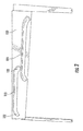
Fig. 1 is a back view of a shower door having two offset rollers and a front view of a panel having two offset tracks configured to receive the two offset rollers of the first shower door panel. -
Fig. 2 is a front view of the panel ofFig. 1 . -
Fig. 3A illustrates a translational motion of the shower door ofFig. 1 along the door panel ofFig. 1 from an open position to a closed position. -
Fig. 3B is a zoomed in view of the shower door ofFig. 3A in the closed position. -
Fig. 3C illustrates a translational motion of the shower door ofFig. 1 along the door panel ofFig. 1 from a closed position to an open position. -
Fig. 3D is a zoomed in view of the shower door ofFig. 3C in the open position. - Before turning to the figures, which illustrate the exemplary embodiments in detail, it should be understood that the present disclosure is not limited to the details or methodology set forth in the description or illustrated in the figures. It should also be understood that the terminology is for the purpose of description only and should not be regarded as limiting. An effort has been made to use the same or like reference numbers throughout the drawings to refer to the same or like parts.
- Referring generally to
Figs. 1-3D , an exemplary embodiment relates to an improved shower door configured to provide a watertight seal around the shower door without installing a threshold, wall jamb or barrier in a showering enclosure. - Referring to the figures more particularly, as illustrated in
Figs. 1 and2 , an exemplary embodiment of a showerdoor cam system 100 includes ashower door 110 having twooffset rollers 111 and apanel 120 having twooffset tracks 121 configured to receive theoffset rollers 111 to assist in a translational motion of theshower door 110. In particular, during translational motion of theshower door 110, theshower door 110 is slid such that each of theoffset rollers 111 roll along a corresponding one of theoffset tracks 121. - In one embodiment, the two
offset rollers 111 are provided at a top portion of a surface of theshower door 110 facing an interior of the showering enclosure. - In an exemplary embodiment, the
panel 120 extends along a top of the showering enclosure, across an entire width of the showering enclosure. Each of the twooffset tracks 121 includes downward-sloping,curved ends 122 with astraight portion 123 disposed between theends 122. Each of the twooffset tracks 121 is symmetrical with respect to a center of thetrack 121 and with respect to the other track 121 (i.e., thefirst offset track 121 has a same size and a same shape as the second offset track 121). - Each of the
offset tracks 121 extends approximately half way across a width of thepanel 120. In one embodiment, the offsettracks 121 are disposed one above the other such that the offsettracks 121 overlap with respect to a vertical center line of thepanel 120. By providing thetracks 121 in an offset and overlapping configuration, as opposed to providing thetracks 121 in a parallel or in a serial configuration, a range of motion of therollers 111 is increased, while still allowing theshower door 110 to be raised and lowered at the appropriate locations (seeFigs. 3A-3D ). A difference in height from a lowest point of thecurved end 122 to thestraight portion 123 determines a height of a gap 150 (seeFig. 3D ) formed between theshower door 110 and ashower floor 130 when theshower door 110 is elevated during its translational motion across a width of the showering enclosure. The translational motion of theshower door 110 will be described in further detail below. - In other embodiments, the
track 122 may have a different shape, provided there is a height difference between the lowest point of anend 122 and thestraight portion 123. For example, a slope from theend 122 to thestraight portion 123 may be more or less steep. In another example, theend 122 may be more or less curved. In yet another example, theend 122 may be linear and provided at a downward slope with respect to thestraight portion 123. - In another exemplary embodiment, the
shower cam system 100 includes two shower doors 110 (seeFigs. 3A-3D ). When twoshower doors 110 are provided, each of the twoshower doors 110 are configured to separately slide across a width of the showering enclosure. In such a configuration, eachshower door 110 includes two offsetrollers 111 as illustrated inFig. 1 , and thepanel 120 includes two sets of offset tracks 121 (i.e., four tracks 121), eachtrack 121 configured to receive asingle roller 111. - Referring now to
Figs. 3A and 3B , when theshower door 110 is in a closed position (i.e., when theshower door 110 abuts a wall of the showering enclosure), each of therollers 111 is located within thecurved end 122 of itsrespective track 121. Referring now toFigs. 3C and 3D , when theshower door 110 is in an open position, for example, when theshower door 110 is being moved from side to side (i.e., translation motion) across a width of the showering enclosure, each of therollers 111 is located within thestraight portion 123 of itsrespective track 121. As a result of the configuration of thetracks 121, when theshower door 110 is in the open position, theshower door 110 is elevated off of the shower floor 130 (see arrows inFigs. 3A-3D indicating translation motion of the shower door 110). When theshower door 110 is in the closed position, theshower door 110 forms a watertight seal along abutting surfaces of the showering enclosure. The watertight seal is configured to contain water within the showering enclosure. - For safety consideration, the height of the gap 150 formed when the
shower door 110 is elevated off of theshower floor 130 during the translational motion of theshower door 110 is preferably small enough such that an appendage (e.g., a user's toe) cannot fit between theshower door 110 and theshower floor 130. - Although the
shower door 110 and thepanel 120 included two offsetrollers 111 and two offsettracks 121, respectively, any other number ofrollers 111 andtracks 121 may be used, provided theshower cam system 100 is capable of the translational motion described above. A predetermined number of offsetrollers 111 used is a same number as a predetermined number of offsettracks 121 used in theshower cam system 100. - According to the embodiments described above, a shower door cam system is provided. The shower door cam system provides a watertight seal around the shower door without installing a threshold, wall jamb or barrier in a showering enclosure.
- As utilized herein, the terms "approximately," "about," "substantially", and similar terms are intended to have a broad meaning in harmony with the common and accepted usage by those of ordinary skill in the art to which the subject matter of this disclosure pertains. It should be understood by those of skill in the art who review this disclosure that these terms are intended to allow a description of certain features described and claimed without restricting the scope of these features to the precise numerical ranges provided. Accordingly, these terms should be interpreted as indicating that insubstantial or inconsequential modifications or alterations of the subject matter described and claimed are considered to be within the scope of the invention as recited in the appended claims.
- It should be noted that the term "exemplary" as used herein to describe various embodiments is intended to indicate that such embodiments are possible examples, representations, and/or illustrations of possible embodiments (and such term is not intended to connote that such embodiments are necessarily extraordinary or superlative examples).
- References herein to the positions of elements (e.g., "top," "bottom," "above," "below," etc.) are merely used to describe the orientation of various elements in the FIGURES. It should be noted that the orientation of various elements may differ according to other exemplary embodiments, and that such variations are intended to be encompassed by the present disclosure.
- It is important to note that the construction and arrangement of the shower door cam system as shown and/or described in the various exemplary embodiments is illustrative only. Although only a few embodiments have been described in detail in this disclosure, those skilled in the art who review this disclosure will readily appreciate that many modifications are possible (e.g., variations in sizes, dimensions, structures, shapes and proportions of the various elements, values of parameters, mounting arrangements, use of materials, colors, orientations, etc.) without materially departing from the novel teachings and advantages of the subject matter described herein. For example, elements shown as integrally formed may be constructed of multiple parts or elements, the position of elements may be reversed or otherwise varied, and the nature or number of discrete elements or positions may be altered or varied. The order or sequence of any process or method steps may be varied or re-sequenced according to alternative embodiments. Other substitutions, modifications, changes and omissions may also be made in the design, operating conditions and arrangement of the various exemplary embodiments without departing from the scope of the present invention.
Claims (15)
- A shower door cam system comprising:at least one shower door having a predetermined number of offset rollers; andat least one panel having the predetermined number of offset tracks, each track configured to receive one of the rollers,wherein in a closed position of the shower door, the shower door contacts a floor of a showering enclosure to form a watertight seal, andwherein in an open position of the shower door, the shower door is elevated such that a gap is formed between the shower door and the floor of the showering enclosure.
- The shower door cam system according to claim 1, wherein the offset tracks overlap with respect to a vertical center line of the panel.
- The shower door cam system according to any of the preceding claims, wherein each track comprises a straight portion disposed between two curved ends.
- The shower door cam system according to claim 3, wherein in the closed position of the shower door, each roller is located within one of the two curved ends of a corresponding track.
- The shower door cam system according to claim 3 or 4, wherein in the open position of the shower door, each roller is located within the straight portion of a corresponding track.
- The shower door cam system according to any of claims 3 to 5, wherein a difference in height from a lowest point of the curved ends to the straight portion determines a height of the gap.
- The shower door cam system according to any of claims 3 to 6, wherein the curved ends are downward-sloping to allow the shower door to contact the floor of the showering enclosure when the rollers are located within the curved ends of the track.
- The shower door cam system any of the preceding claims, wherein the rollers are provided at a top portion of a surface of the shower door configured to face an interior of the showering enclosure.
- The shower door cam system according to any of the preceding claims, wherein each of the tracks extends approximately halfway across a width of the panel.
- The shower door cam system according to any of the preceding claims, wherein the panel extends across an entire width of the showering enclosure.
- The shower door cam system according to any of the preceding claims, wherein each of the tracks is symmetrical with respect to a center of the track.
- The shower door cam system according to any of the preceding claims, wherein each of the tracks has a same size and a same shape.
- The shower door cam system according to any of the preceding claims, wherein the shower door cam system comprises two shower doors, each of the shower doors configured to separately slide across a width of the showering enclosure.
- The shower door cam system of claim 13, wherein each shower door includes the predetermined number of offset rollers and the panel includes two times the predetermined number of offset tracks, each track configured to receive one of the rollers of one of the shower doors.
- The shower door cam system according to any of the preceding claims, wherein the shower door is configured to form a watertight seal without including a threshold, a wall jamb or a barrier in the showering enclosure.
Applications Claiming Priority (1)
| Application Number | Priority Date | Filing Date | Title |
|---|---|---|---|
| US201361793393P | 2013-03-15 | 2013-03-15 |
Publications (1)
| Publication Number | Publication Date |
|---|---|
| EP2777461A1 true EP2777461A1 (en) | 2014-09-17 |
Family
ID=50272530
Family Applications (1)
| Application Number | Title | Priority Date | Filing Date |
|---|---|---|---|
| EP14160134.4A Withdrawn EP2777461A1 (en) | 2013-03-15 | 2014-03-14 | Shower door cam system |
Country Status (3)
| Country | Link |
|---|---|
| US (1) | US9462915B2 (en) |
| EP (1) | EP2777461A1 (en) |
| CN (1) | CN104047527A (en) |
Cited By (1)
| Publication number | Priority date | Publication date | Assignee | Title |
|---|---|---|---|---|
| WO2020119034A1 (en) * | 2018-12-13 | 2020-06-18 | 福建西河卫浴科技有限公司 | Roller device and shower room |
Families Citing this family (2)
| Publication number | Priority date | Publication date | Assignee | Title |
|---|---|---|---|---|
| US9980614B2 (en) * | 2016-08-17 | 2018-05-29 | Liberty Hardware Mfg. Corp. | Base member for a shower door assembly |
| CN107975324B (en) * | 2016-10-25 | 2019-08-13 | 深圳市祈飞科技有限公司 | Seal vertical hinged door |
Citations (3)
| Publication number | Priority date | Publication date | Assignee | Title |
|---|---|---|---|---|
| JP2003343164A (en) * | 2002-05-28 | 2003-12-03 | Matsushita Electric Works Ltd | Waterproofing structure for bathroom sliding door |
| WO2004022894A1 (en) * | 2002-09-03 | 2004-03-18 | Rytec Corporation | Dual overhead track for a sliding door |
| DE102007028473A1 (en) * | 2007-06-18 | 2008-12-24 | Kermi Gmbh | Sliding door and shower enclosure with sliding door |
Family Cites Families (13)
| Publication number | Priority date | Publication date | Assignee | Title |
|---|---|---|---|---|
| US433256A (en) | 1890-07-29 | Car-door | ||
| US1045284A (en) | 1912-05-21 | 1912-11-26 | Harry M Haun | Ball-bearing door-hanger. |
| US1990542A (en) | 1930-03-27 | 1935-02-12 | Railway Metal Products Company | Railway car door fixture |
| NL110557C (en) | 1963-01-14 | |||
| FR2511070A1 (en) | 1981-08-05 | 1983-02-11 | Fermod | DEVICE FOR THE SUSPENSION OF A SLIDING SEALED DOOR |
| US4619075A (en) | 1984-09-19 | 1986-10-28 | Jamison Door Company | Horizontal sliding door |
| EP0225675B1 (en) | 1985-12-13 | 1990-07-25 | Johannes Joseph Maria Kompier | A basic unit for the erection of a sliding-door |
| US5461829A (en) | 1994-08-29 | 1995-10-31 | Kason Industries, Inc. | Trolley rail system for sliding door |
| AU6475496A (en) | 1996-05-23 | 1997-12-09 | Ready Access, Inc. | Self closing sliding access door |
| US6497072B2 (en) | 1997-01-10 | 2002-12-24 | Frip Ab | Sliding panel for longitudinal and lateral movement in a frame structure |
| US6539669B1 (en) | 2000-09-14 | 2003-04-01 | Westinghouse Air Brake Technologies Corporation | Plug door drive system |
| CN201460606U (en) | 2009-04-09 | 2010-05-12 | 颜海广 | shower room glass door |
| CN202596467U (en) | 2012-05-31 | 2012-12-12 | 中山市莎丽卫浴设备有限公司 | A hidden track door |
-
2014
- 2014-03-13 US US14/208,833 patent/US9462915B2/en active Active
- 2014-03-14 CN CN201410097510.5A patent/CN104047527A/en active Pending
- 2014-03-14 EP EP14160134.4A patent/EP2777461A1/en not_active Withdrawn
Patent Citations (3)
| Publication number | Priority date | Publication date | Assignee | Title |
|---|---|---|---|---|
| JP2003343164A (en) * | 2002-05-28 | 2003-12-03 | Matsushita Electric Works Ltd | Waterproofing structure for bathroom sliding door |
| WO2004022894A1 (en) * | 2002-09-03 | 2004-03-18 | Rytec Corporation | Dual overhead track for a sliding door |
| DE102007028473A1 (en) * | 2007-06-18 | 2008-12-24 | Kermi Gmbh | Sliding door and shower enclosure with sliding door |
Cited By (1)
| Publication number | Priority date | Publication date | Assignee | Title |
|---|---|---|---|---|
| WO2020119034A1 (en) * | 2018-12-13 | 2020-06-18 | 福建西河卫浴科技有限公司 | Roller device and shower room |
Also Published As
| Publication number | Publication date |
|---|---|
| US9462915B2 (en) | 2016-10-11 |
| CN104047527A (en) | 2014-09-17 |
| US20140259365A1 (en) | 2014-09-18 |
Similar Documents
| Publication | Publication Date | Title |
|---|---|---|
| US10610060B2 (en) | Shower door assemblies and methods for installing same | |
| US9249616B2 (en) | Shower door jamb seal | |
| CA2853462C (en) | Sliding shower door assembly | |
| AU2013100819A4 (en) | Door assembly | |
| US10123660B2 (en) | Shower door assembly | |
| US9462915B2 (en) | Shower door cam system | |
| MX352725B (en) | Wind lock configuration for overhead roll-up doors. | |
| US10278547B2 (en) | Door assembly for a bathing enclosure | |
| US10278546B2 (en) | Base member for a shower door assembly | |
| ITPD20110001A1 (en) | BUILT-IN ELECTRIC APPLIANCES AND ASSEMBLY OF BUILT-IN AND MOBILE APPLIANCES FOR BUILT-IN APPLIANCES. | |
| US5657581A (en) | Multiple section suspended bath doors with interlocking members | |
| AU2014258998A1 (en) | System and device for soft closing | |
| CN105492714B (en) | Shower door assemblies and shower doors | |
| EP2777462A1 (en) | Shower door seal system | |
| KR20190046771A (en) | A sliding wall device having a cover member | |
| US10947757B2 (en) | Interlock security device | |
| CA2859532C (en) | Sliding shower door guide and drain assembly | |
| EP3061899B1 (en) | Shower door frame and shower door | |
| KR20180134495A (en) | Sliding window having hidden type rail | |
| EP3133229B1 (en) | Window or door locking system | |
| CN209509936U (en) | The mounting structure of bathroom sliding door | |
| KR101262766B1 (en) | The structure of window | |
| DE202004009706U1 (en) | Shower tray or bath has bar magnets mounted along its sides which cooperate with magnetic sealing strip along bottom edge of shower cubicle door | |
| DE102010015852A1 (en) | Shower device for use in toilet of building, has lower edge shifted from use position to relative position by rolling or sliding device that is fixed accurately to shower base, such that sealing is provided against emerging shower water | |
| GB2435275A (en) | Support device for a cavity closer |
Legal Events
| Date | Code | Title | Description |
|---|---|---|---|
| 17P | Request for examination filed |
Effective date: 20140314 |
|
| AK | Designated contracting states |
Kind code of ref document: A1 Designated state(s): AL AT BE BG CH CY CZ DE DK EE ES FI FR GB GR HR HU IE IS IT LI LT LU LV MC MK MT NL NO PL PT RO RS SE SI SK SM TR |
|
| AX | Request for extension of the european patent |
Extension state: BA ME |
|
| PUAI | Public reference made under article 153(3) epc to a published international application that has entered the european phase |
Free format text: ORIGINAL CODE: 0009012 |
|
| STAA | Information on the status of an ep patent application or granted ep patent |
Free format text: STATUS: THE APPLICATION IS DEEMED TO BE WITHDRAWN |
|
| 18D | Application deemed to be withdrawn |
Effective date: 20150318 |