EP2775983B1 - Warming therapy device including mattress temperature correction - Google Patents
Warming therapy device including mattress temperature correction Download PDFInfo
- Publication number
- EP2775983B1 EP2775983B1 EP11785260.8A EP11785260A EP2775983B1 EP 2775983 B1 EP2775983 B1 EP 2775983B1 EP 11785260 A EP11785260 A EP 11785260A EP 2775983 B1 EP2775983 B1 EP 2775983B1
- Authority
- EP
- European Patent Office
- Prior art keywords
- temperature
- correction factor
- air temperature
- measured
- humidity
- Prior art date
- Legal status (The legal status is an assumption and is not a legal conclusion. Google has not performed a legal analysis and makes no representation as to the accuracy of the status listed.)
- Active
Links
Images


Classifications
-
- A—HUMAN NECESSITIES
- A61—MEDICAL OR VETERINARY SCIENCE; HYGIENE
- A61F—FILTERS IMPLANTABLE INTO BLOOD VESSELS; PROSTHESES; DEVICES PROVIDING PATENCY TO, OR PREVENTING COLLAPSING OF, TUBULAR STRUCTURES OF THE BODY, e.g. STENTS; ORTHOPAEDIC, NURSING OR CONTRACEPTIVE DEVICES; FOMENTATION; TREATMENT OR PROTECTION OF EYES OR EARS; BANDAGES, DRESSINGS OR ABSORBENT PADS; FIRST-AID KITS
- A61F7/00—Heating or cooling appliances for medical or therapeutic treatment of the human body
- A61F7/0053—Cabins, rooms, chairs or units for treatment with a hot or cold circulating fluid
-
- A—HUMAN NECESSITIES
- A61—MEDICAL OR VETERINARY SCIENCE; HYGIENE
- A61G—TRANSPORT, PERSONAL CONVEYANCES, OR ACCOMMODATION SPECIALLY ADAPTED FOR PATIENTS OR DISABLED PERSONS; OPERATING TABLES OR CHAIRS; CHAIRS FOR DENTISTRY; FUNERAL DEVICES
- A61G11/00—Baby-incubators; Couveuses
-
- G—PHYSICS
- G05—CONTROLLING; REGULATING
- G05D—SYSTEMS FOR CONTROLLING OR REGULATING NON-ELECTRIC VARIABLES
- G05D22/00—Control of humidity
- G05D22/02—Control of humidity characterised by the use of electric means
-
- G—PHYSICS
- G05—CONTROLLING; REGULATING
- G05D—SYSTEMS FOR CONTROLLING OR REGULATING NON-ELECTRIC VARIABLES
- G05D23/00—Control of temperature
- G05D23/19—Control of temperature characterised by the use of electric means
-
- G—PHYSICS
- G05—CONTROLLING; REGULATING
- G05D—SYSTEMS FOR CONTROLLING OR REGULATING NON-ELECTRIC VARIABLES
- G05D27/00—Simultaneous control of variables covered by two or more of main groups G05D1/00 - G05D25/00
- G05D27/02—Simultaneous control of variables covered by two or more of main groups G05D1/00 - G05D25/00 characterised by the use of electric means
-
- A—HUMAN NECESSITIES
- A61—MEDICAL OR VETERINARY SCIENCE; HYGIENE
- A61F—FILTERS IMPLANTABLE INTO BLOOD VESSELS; PROSTHESES; DEVICES PROVIDING PATENCY TO, OR PREVENTING COLLAPSING OF, TUBULAR STRUCTURES OF THE BODY, e.g. STENTS; ORTHOPAEDIC, NURSING OR CONTRACEPTIVE DEVICES; FOMENTATION; TREATMENT OR PROTECTION OF EYES OR EARS; BANDAGES, DRESSINGS OR ABSORBENT PADS; FIRST-AID KITS
- A61F7/00—Heating or cooling appliances for medical or therapeutic treatment of the human body
- A61F2007/0054—Heating or cooling appliances for medical or therapeutic treatment of the human body with a closed fluid circuit, e.g. hot water
- A61F2007/0055—Heating or cooling appliances for medical or therapeutic treatment of the human body with a closed fluid circuit, e.g. hot water of gas, e.g. hot air or steam
-
- A—HUMAN NECESSITIES
- A61—MEDICAL OR VETERINARY SCIENCE; HYGIENE
- A61F—FILTERS IMPLANTABLE INTO BLOOD VESSELS; PROSTHESES; DEVICES PROVIDING PATENCY TO, OR PREVENTING COLLAPSING OF, TUBULAR STRUCTURES OF THE BODY, e.g. STENTS; ORTHOPAEDIC, NURSING OR CONTRACEPTIVE DEVICES; FOMENTATION; TREATMENT OR PROTECTION OF EYES OR EARS; BANDAGES, DRESSINGS OR ABSORBENT PADS; FIRST-AID KITS
- A61F7/00—Heating or cooling appliances for medical or therapeutic treatment of the human body
- A61F2007/0086—Heating or cooling appliances for medical or therapeutic treatment of the human body with a thermostat
-
- A—HUMAN NECESSITIES
- A61—MEDICAL OR VETERINARY SCIENCE; HYGIENE
- A61G—TRANSPORT, PERSONAL CONVEYANCES, OR ACCOMMODATION SPECIALLY ADAPTED FOR PATIENTS OR DISABLED PERSONS; OPERATING TABLES OR CHAIRS; CHAIRS FOR DENTISTRY; FUNERAL DEVICES
- A61G2203/00—General characteristics of devices
- A61G2203/30—General characteristics of devices characterised by sensor means
- A61G2203/46—General characteristics of devices characterised by sensor means for temperature
Definitions
- This present invention relates generally to a method and apparatus for performing warming therapy on medical patients. Most particularly, the present invention relates to a method and apparatus for adjusting the temperature within an enclosure while accounting for the humidity level.
- warming therapy devices e.g., incubators, warmers, etc.
- systems which are designed to control the temperature and humidity of the environment surrounding an infant patient disposed inside a hood of the warming therapy device.
- the temperature within the warming therapy device may be adjusted using a heating element located within the air circulation system of the warming therapy device, which is responsive to a temperature sensor.
- the humidity within a warming therapy device may be adjusted using a humidification device that is adapted to inject humidity into the air circulation system of the warming therapy device.
- Humidification systems typically comprise at least a water reservoir, a boiling chamber, and a heating element.
- the heating element typically acts to heat the water within the boiling chamber, and thus create humidity by adding water vapor to heated air.
- the temperature and humidity concentration of the air within a warming therapy device are typically controlled by a forced air circulation system, where the impeller of a fan unit recirculates the air. Temperature is generally measured with a sensor located inside of the incubator compartment. However, the temperature measurement can be incorrect due to the changing density of the air resulting from higher humidity levels inside of the incubator. Because one of the objectives of a warming therapy device is to create an environment with a specific prescribed temperature level, which requires accurate measurements of the temperature inside the enclosure, there is a need to correct temperatures which may not be accurately measured due to environmental conditions.
- the present invention comprises a warming therapy apparatus, including a base for supporting a medical patient, a hood surrounding a portion of the base, a heater for heating the air inside the hood, a sensor for measuring an air temperature and a humidity inside the hood, and a controller for adjusting the air temperature based on the measured humidity and a correction factor.
- the present invention comprises a method of adjusting the air temperature inside an enclosure for medical patients, including the steps of measuring the air temperature at a predetermined location inside the enclosure, measuring the humidity inside the enclosure, determining a correction factor, applying the correction factor to the measured air temperature to determine a temperature correction value, and adjusting the air temperature inside the enclosure based on the temperature correction value.
- the present invention relates to a warming therapy device (e.g. incubator, warmer, etc.) including a humidification system and a temperature adjustment system which accurately measures the temperature of the air inside the warming therapy device.
- a warming therapy device e.g. incubator, warmer, etc.
- a humidification system e.g. a humidification system
- a temperature adjustment system which accurately measures the temperature of the air inside the warming therapy device.
- the temperature adjustment system may be used in connection with an incubator and temperature sensor such as are disclosed and discussed in U.S. Pat No. 5,730,355 (assigned to the same assignee as the present application).
- U.S. Pat, No. 5,730,355 describes an incubator having a base 16 and a sensor module 44 for sensing conditions such as air temperature and humidity within the incubator, and providing control signals for regulating the same.
- Closed care warming therapy devices provide physical separation between the environment where the infant patient is disposed and the surrounding ambient air. This separation is typically provided by a hood or similar member which encloses the infant patient therein. This encapsulation of the infant patient facilitates creation of conditions favorable for the infant patient's development. Often times, the conditions inside the hood can be significantly different from those present in the ambient environment. Conditions inside the hood may be determined by varying the temperature level and/or humidity concentration within the closed care environment, all of which can be controlled automatically using sensors integrated in the warming therapy device. For example, the temperature within the closed care environment may be controlled by sensing the skin temperature of the infant patient or the temperature at a location within the hood and making appropriate adjustments.
- Figure 1 discussed below, show an exemplary closed care warming therapy device.
- Medical patients are generally placed on a mattress in the base of a warming therapy device.
- sensors are generally placed on the hood of a warming therapy device to measure the temperature of the air inside the enclosure. Due to the differences in location between the sensor and mattress, temperature measurements of the air inside the warming therapy device may differ.
- the sensor measures the air within a warming therapy device.
- a controller applies an offset to account for the difference in air temperatures between the location of the sensor and the medical patient.
- the sensor does not account for incorrect air temperature measurements due to changing air density resulting from humidity fluctuations in the warming therapy device.
- the present invention provides systems and methods for correcting the air temperature such that it accurately mirrors the air temperature as measured in the vicinity of a mattress in a warming therapy device by adjusting the air temperature based on humidity in the warming therapy device.
- Figure 1 provides a closed care warming therapy device 100 comprising a hood 10 and a base 16.
- the hood 10 has access door 12 in wall 14 and access door 20 in wall 22, for example.
- the hood 10 is mounted on base 16, which comprises a deck 18.
- the deck 18 includes openings 24, 26, 28 which allow for air to enter and leave the enclosure as indicated by the arrows leaving openings 24, 26 and entering opening 28.
- the air passing through opening 24 in deck 18 forms a warm air curtain, which serves as a barrier and reduces the effect of the ambient temperature outside the incubator on the enclosure area.
- the air passing through opening 26 in deck 18 forms a warm air curtain, similar to when door 12 is opened.
- the warming therapy device 100 further comprises a first inner wall 30 and a second inner wall 31, secured to doors 12 and 20, respectively-
- the first inner wall 30 and the second inner wall 31 are moveable with their corresponding doors 12, 20.
- the inner walls 30, 31 reduce radiant heat losses when the respective access doors are closed and serve to carry warm air introduced through openings 24, 26 to the top of hood 10 as shown by the arrows inside of the hood 10.
- the hood 10 also includes a sensor 44 which is able to measure the temperature of the air and humidity inside the enclosure.
- FIG. 2 illustrates the system 200 for adjusting the temperature of the air inside the enclosure by accounting for effects on the measured temperature of the air inside the enclosure between the hood 10 and base 20 caused by changes in the density of air due to fluctuations in humidity within the enclosure.
- System 200 includes a warming therapy device 100 comprising a hood 10, which includes a sensor 44, and a base 16.
- a mattress 40 is supported by base 16.
- the system 200 further includes a correction factor determination unit 210, display 220, air temperature controller 230, air set 240, humidity controller 250, RH set 260, main heater 270, and humidity heater 290.
- Sensor 44 includes a humidity sensor and temperature sensor. However, separate humidity and temperature sensors may be used.
- the sensor 44 measures the air temperature and humidity in the enclosure.
- the corrected temperature value as calculated by the correction factor determination unit 210 and the humidity received from the sensor 44 are displayed on the display 220.
- the correction factor determination unit 210 receives a measured temperature of the air and humidity in the enclosure from sensor 44.
- the correction factor determination unit 210 provides a corrected temperature value to air temperature controller 230, which adjusts the main heater 270 accordingly.
- the sensor 44 also provides the measured humidity to the humidity controller 250 which adjusts the humidity of the enclosure through the humidity heater 280.
- the correction factor determination unit 210 provides a corrected temperature value based on the measured humidity and measured air temperature in the enclosure between hood 10 and base 16.
- the corrected temperature calculated by the correction factor determination unit 210 is the sum of the measured air temperature provided by sensor 44 and a correction factor, for example.
- the correction factor is based on the measured humidity and is calculated with the following equation by the correction factor determination unit 210.
- correction factor ⁇ * RH % 2 + ⁇ * RH % + ⁇ where RH is the measured relative humidity.
- ⁇ may be -0.000189, for example; ⁇ may be 0.032867, for example; and ⁇ may be -1.8378, for example.
- values are provided for ⁇ , ⁇ , ⁇ , these variables are not limited to these values the provided values.
- polynomials of an order other than quadratic may also be used.
- the correction factor determination unit 210 provides a control signal to the air temperature controller 230, which then adjusts the temperature of the air in the enclosure of the warming therapy apparatus 100 witch main heater 270.
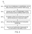
- a process 300 for adjusting the temperature of the air within an enclosure of a warming therapy device is illustrated.
- the air temperature is measured in the enclosure between hood 10 and base 16 of the warming therapy apparatus 100 at a predetermined location (S302).
- the air temperature may be measured by sensor 44 as illustrated in Figure 2 , for example.
- the humidity of the enclosure is also measured at a predetermined location inside the enclosure of the warming therapy apparatus 100 (S304).
- the humidity of the enclosure may also be measured by sensor 44, for example.
- a correction factor to apply to the measured air temperature is determined based on the measured humidity (S306).
- the correction factor determination unit 210 may determine the correction factor, for example.
- ⁇ may be -0.000189, for example; ⁇ may be 0.032867, for example; and ⁇ may be -1.8378, for example.
- values are provided for ⁇ , ⁇ , ⁇ , these variables are not limited to these values the provided values.
- polynomials of an order other than quadratic may also be used.
- the temperature of the air inside the enclosure is adjusted to the corrected temperature.
- the correction factor determination 210 may provide a control signal with the corrected temperature or temperature adjustment to the air temperature controller 230 which controls the main heater 270 to adjust the temperature of the enclosure to the corrected temperature.
- Table 1 below shows how the air temperature as measured from the center mattress location 50 differs from the temperature of the air as measured by sensor 44 when the relative humidity of the enclosure changes.
- the center mattress location 50 corresponds to a position that a patient would be placed on a mattress within the enclosure of the warming therapy device 100.
- Table 1 also summarizes the corrected temperature calculated with techniques disclosed in the present disclosure and the corrected temperature calculated with the previous method. As will be seen in Chart 1 below, the corrected temperature calculated with embodiments of the present disclosure more accurately provides the temperature of the air in the enclosure and mirrors the temperature of the air measured at the center mattress location 50 providing an accurate temperature environment for a patient located on the mattress of the warming therapy device.
- Chart 1 bellow shows a comparison of the air temperature measured at the center mattress location 50, the corrected air temperature based on a correction that is not a function of the relative humidity, or the previous method, and the corrected air temperature based on embodiments of the present disclosure.
- the corrected air temperature based on the measured relative humidity more accurately tracks the air temperature measured at the center mattress location 50 than the corrected air temperature based on a correction that is not a function of the relative humidity. Based on the more accurate prediction of the center mattress temperature measurement provided by the corrected air temperature, the benefits of the present invention can be appreciated.
Landscapes
- Health & Medical Sciences (AREA)
- Engineering & Computer Science (AREA)
- Physics & Mathematics (AREA)
- General Physics & Mathematics (AREA)
- Automation & Control Theory (AREA)
- Life Sciences & Earth Sciences (AREA)
- Animal Behavior & Ethology (AREA)
- General Health & Medical Sciences (AREA)
- Public Health (AREA)
- Veterinary Medicine (AREA)
- Biomedical Technology (AREA)
- Heart & Thoracic Surgery (AREA)
- Vascular Medicine (AREA)
- Pediatric Medicine (AREA)
- Pregnancy & Childbirth (AREA)
- Gynecology & Obstetrics (AREA)
- Accommodation For Nursing Or Treatment Tables (AREA)
- Air Conditioning Control Device (AREA)
Description
- This present invention relates generally to a method and apparatus for performing warming therapy on medical patients. Most particularly, the present invention relates to a method and apparatus for adjusting the temperature within an enclosure while accounting for the humidity level.
- It is known to control both the temperature and relative humidity of the air adjacent a medical patient (e.g., infant) in a warming therapy device. For example, many warming therapy devices (e.g., incubators, warmers, etc.) include systems which are designed to control the temperature and humidity of the environment surrounding an infant patient disposed inside a hood of the warming therapy device. To control the temperature and humidity within the warming therapy device, the existing temperature and humidity are sensed and then adjusted. The temperature within the warming therapy device may be adjusted using a heating element located within the air circulation system of the warming therapy device, which is responsive to a temperature sensor. The humidity within a warming therapy device may be adjusted using a humidification device that is adapted to inject humidity into the air circulation system of the warming therapy device.
- Humidification systems typically comprise at least a water reservoir, a boiling chamber, and a heating element. The heating element typically acts to heat the water within the boiling chamber, and thus create humidity by adding water vapor to heated air. The temperature and humidity concentration of the air within a warming therapy device are typically controlled by a forced air circulation system, where the impeller of a fan unit recirculates the air. Temperature is generally measured with a sensor located inside of the incubator compartment. However, the temperature measurement can be incorrect due to the changing density of the air resulting from higher humidity levels inside of the incubator. Because one of the objectives of a warming therapy device is to create an environment with a specific prescribed temperature level, which requires accurate measurements of the temperature inside the enclosure, there is a need to correct temperatures which may not be accurately measured due to environmental conditions.
- The invention is defined in the attached independent claims, to which reference should now be made. Further, optional features are defined in the subclaims appended thereto.
- In first exemplary embodiment, the present invention comprises a warming therapy apparatus, including a base for supporting a medical patient, a hood surrounding a portion of the base, a heater for heating the air inside the hood, a sensor for measuring an air temperature and a humidity inside the hood, and a controller for adjusting the air temperature based on the measured humidity and a correction factor.
- In a another exemplary embodiment, the present invention comprises a method of adjusting the air temperature inside an enclosure for medical patients, including the steps of measuring the air temperature at a predetermined location inside the enclosure, measuring the humidity inside the enclosure, determining a correction factor, applying the correction factor to the measured air temperature to determine a temperature correction value, and adjusting the air temperature inside the enclosure based on the temperature correction value.
-
-
Figure 1 is an exploded perspective view of a warming therapy device according to an exemplary embodiment of the present invention. -
Figure 2 is a system for adjusting the air temperature by accounting for changes in air density caused by humidity. -
Figure 3 is a process for adjusting the temperature of the air within an enclosure of a warming therapy device by accounting for changes in air density caused by humidity. - The present invention relates to a warming therapy device (e.g. incubator, warmer, etc.) including a humidification system and a temperature adjustment system which accurately measures the temperature of the air inside the warming therapy device.
- By way of example, the temperature adjustment system according to an embodiment of the present invention may be used in connection with an incubator and temperature sensor such as are disclosed and discussed in
U.S. Pat No. 5,730,355 (assigned to the same assignee as the present application). For example,U.S. Pat, No. 5,730,355 describes an incubator having abase 16 and asensor module 44 for sensing conditions such as air temperature and humidity within the incubator, and providing control signals for regulating the same. - Closed care warming therapy devices (e.g., incubators) provide physical separation between the environment where the infant patient is disposed and the surrounding ambient air. This separation is typically provided by a hood or similar member which encloses the infant patient therein. This encapsulation of the infant patient facilitates creation of conditions favorable for the infant patient's development. Often times, the conditions inside the hood can be significantly different from those present in the ambient environment. Conditions inside the hood may be determined by varying the temperature level and/or humidity concentration within the closed care environment, all of which can be controlled automatically using sensors integrated in the warming therapy device. For example, the temperature within the closed care environment may be controlled by sensing the skin temperature of the infant patient or the temperature at a location within the hood and making appropriate adjustments.
Figure 1 , discussed below, show an exemplary closed care warming therapy device. - Medical patients are generally placed on a mattress in the base of a warming therapy device. In addition, sensors are generally placed on the hood of a warming therapy device to measure the temperature of the air inside the enclosure. Due to the differences in location between the sensor and mattress, temperature measurements of the air inside the warming therapy device may differ. The sensor measures the air within a warming therapy device. A controller applies an offset to account for the difference in air temperatures between the location of the sensor and the medical patient. However, the sensor does not account for incorrect air temperature measurements due to changing air density resulting from humidity fluctuations in the warming therapy device. Accordingly, the present invention provides systems and methods for correcting the air temperature such that it accurately mirrors the air temperature as measured in the vicinity of a mattress in a warming therapy device by adjusting the air temperature based on humidity in the warming therapy device.
-
Figure 1 provides a closed carewarming therapy device 100 comprising ahood 10 and abase 16. Thehood 10 hasaccess door 12 in wall 14 andaccess door 20 in wall 22, for example. Thehood 10 is mounted onbase 16, which comprises a deck 18. The area between the inside ofhood 10 and deck 18, when thehood 10 is placed on thebase 16, defines the enclosure. The deck 18 includesopenings arrows leaving openings 24, 26 and entering opening 28. - When the
door 12 of thehood 10 is opened, the air passing through opening 24 in deck 18 forms a warm air curtain, which serves as a barrier and reduces the effect of the ambient temperature outside the incubator on the enclosure area. Whendoor 20 ofhood 10 is opened, the air passing through opening 26 in deck 18 forms a warm air curtain, similar to whendoor 12 is opened. - The
warming therapy device 100 further comprises a first inner wall 30 and a second inner wall 31, secured todoors corresponding doors openings 24, 26 to the top ofhood 10 as shown by the arrows inside of thehood 10. - The
hood 10 also includes asensor 44 which is able to measure the temperature of the air and humidity inside the enclosure. -
Figure 2 illustrates thesystem 200 for adjusting the temperature of the air inside the enclosure by accounting for effects on the measured temperature of the air inside the enclosure between thehood 10 andbase 20 caused by changes in the density of air due to fluctuations in humidity within the enclosure.System 200 includes awarming therapy device 100 comprising ahood 10, which includes asensor 44, and abase 16. Amattress 40 is supported bybase 16. Thesystem 200 further includes a correctionfactor determination unit 210,display 220,air temperature controller 230, air set 240,humidity controller 250,RH set 260,main heater 270, andhumidity heater 290. -
Sensor 44 includes a humidity sensor and temperature sensor. However, separate humidity and temperature sensors may be used. Thesensor 44 measures the air temperature and humidity in the enclosure. The corrected temperature value as calculated by the correctionfactor determination unit 210 and the humidity received from thesensor 44 are displayed on thedisplay 220. - The correction
factor determination unit 210 receives a measured temperature of the air and humidity in the enclosure fromsensor 44. The correctionfactor determination unit 210 provides a corrected temperature value toair temperature controller 230, which adjusts themain heater 270 accordingly. Thesensor 44 also provides the measured humidity to thehumidity controller 250 which adjusts the humidity of the enclosure through thehumidity heater 280. - The correction
factor determination unit 210 provides a corrected temperature value based on the measured humidity and measured air temperature in the enclosure betweenhood 10 andbase 16. The corrected temperature calculated by the correctionfactor determination unit 210 is the sum of the measured air temperature provided bysensor 44 and a correction factor, for example. In more detail, the correction factor is based on the measured humidity and is calculated with the following equation by the correctionfactor determination unit 210.
- Once the correction factor is determined by the correction
factor determination unit 210, the correctionfactor determination unit 210 provides a control signal to theair temperature controller 230, which then adjusts the temperature of the air in the enclosure of the warmingtherapy apparatus 100 witchmain heater 270. - Referring to
Figure 3 , aprocess 300 for adjusting the temperature of the air within an enclosure of a warming therapy device is illustrated. The air temperature is measured in the enclosure betweenhood 10 andbase 16 of the warmingtherapy apparatus 100 at a predetermined location (S302). The air temperature may be measured bysensor 44 as illustrated inFigure 2 , for example. The humidity of the enclosure is also measured at a predetermined location inside the enclosure of the warming therapy apparatus 100 (S304). The humidity of the enclosure may also be measured bysensor 44, for example. A correction factor to apply to the measured air temperature is determined based on the measured humidity (S306). The correctionfactor determination unit 210 may determine the correction factor, for example. The correction factor is based on the measured relative humidity (RH) and is determined through use of the following equation:
- The determined correction factor is applied to the measured temperature to determine the corrected temperature (S308). For example, the correction factor is added to the measured temperature to arrive at the corrected temperature. This calculation is represented in the equation below.

- The temperature of the air inside the enclosure is adjusted to the corrected temperature. (S310). For example, the
correction factor determination 210 may provide a control signal with the corrected temperature or temperature adjustment to theair temperature controller 230 which controls themain heater 270 to adjust the temperature of the enclosure to the corrected temperature. - Table 1 below shows how the air temperature as measured from the center mattress location 50 differs from the temperature of the air as measured by
sensor 44 when the relative humidity of the enclosure changes. The center mattress location 50 corresponds to a position that a patient would be placed on a mattress within the enclosure of the warmingtherapy device 100. Table 1 also summarizes the corrected temperature calculated with techniques disclosed in the present disclosure and the corrected temperature calculated with the previous method. As will be seen inChart 1 below, the corrected temperature calculated with embodiments of the present disclosure more accurately provides the temperature of the air in the enclosure and mirrors the temperature of the air measured at the center mattress location 50 providing an accurate temperature environment for a patient located on the mattress of the warming therapy device.Table 1 Relative Humidity (RH) [%] Temperature as measured by sensor Corrected temperature calculated with the previous method Measured temperature at center mattress location Corrected temperature calculated with embodiments of present disclosure 24 31.2 30.1 30 30.0 30 31.2 30.1 30.3 30.2 40 31.1 30 30.5 30.3 50 31.1 30 30.6 30.4 60 31.1 30 30.7 30.6 70 31.1 30 30.8 30.6 80 31.1 30 30.8 30.7 90 31.1 30 30.9 30.7 95 31.1 30 31 30.7 -
Chart 1 bellow shows a comparison of the air temperature measured at the center mattress location 50, the corrected air temperature based on a correction that is not a function of the relative humidity, or the previous method, and the corrected air temperature based on embodiments of the present disclosure. As can be seen, the corrected air temperature based on the measured relative humidity more accurately tracks the air temperature measured at the center mattress location 50 than the corrected air temperature based on a correction that is not a function of the relative humidity. Based on the more accurate prediction of the center mattress temperature measurement provided by the corrected air temperature, the benefits of the present invention can be appreciated.
- Although the apparatus and methods have been described in connection with specific forms thereof, it will be appreciated that a wide variety of equivalents may be substituted for the specified elements described herein without departing from the scope of this disclosure as described in the appended claims.
Claims (12)
- A warming therapy apparatus (100), comprising:a base (16) for supporting a medical patient;a hood (10) surrounding a portion of the base (16);a heater (270, 280) for heating the air inside the hood (10);a sensor (44) for measuring an air temperature and a humidity inside the hood (10);characterized in that it further comprises
a correction factor determination unit (210) which calculates the correction factor based on the measured humidity within the hood (10); and
a controller (230, 250) for adjusting the air temperature based on the correction factor. - The warming therapy apparatus (100) of claim 1, wherein the controller (230) adjusts the air temperature by changing the air temperature to the sum of the correction factor and the measured air temperature.
- The warming therapy apparatus (100) of claim 1, wherein the correction factor determination unit (210) determines a corrected air temperature; and wherein the apparatus comprises an air temperature controller (230) which receives a control signal from the correction factor determination unit (210), and adjusts the air temperature accordingly.
- The apparatus (100) of claim 3, wherein the correction factor determination unit (210) calculates the corrected air temperature by determining the sum of the measured air temperature and the calculated correction factor.
- The apparatus (100) of any preceding claim, wherein the correction factor is a polynomial of the measured humidity.
- The apparatus (100) of any preceding claim, wherein the correction factor is a quadratic polynomial of the measured humidity.
- A method of adjusting the air temperature inside an enclosure (10) for medical patients, comprising:measuring the air temperature at a predetermined location inside the enclosure (10);measuring the humidity inside the enclosure (10);determining a correction factor based on the measured humidity;applying the correction factor to the measured air temperature to determine a temperature correction value; andadjusting the air temperature inside the enclosure (10) based on the temperature correction value.
- The method of claim 7, wherein the air temperature inside the enclosure is measured with a sensor (44).
- The method of claim 7, wherein the humidity inside of the enclosure is measured with a sensor (44).
- The method of claim 7, wherein the temperature correction value is the sum of the correction factor and the measured air temperature.
- The method of claim 7, wherein the correction factor is a polynomial of the measured humidity.
- The method of claim 7 wherein the correction factor is a quadratic polynomial of the measured humidity.
Applications Claiming Priority (1)
| Application Number | Priority Date | Filing Date | Title |
|---|---|---|---|
| PCT/US2011/060190 WO2013070229A1 (en) | 2011-11-10 | 2011-11-10 | Warming therapy device including mattress temperature correction |
Publications (2)
| Publication Number | Publication Date |
|---|---|
| EP2775983A1 EP2775983A1 (en) | 2014-09-17 |
| EP2775983B1 true EP2775983B1 (en) | 2016-03-09 |
Family
ID=44999963
Family Applications (1)
| Application Number | Title | Priority Date | Filing Date |
|---|---|---|---|
| EP11785260.8A Active EP2775983B1 (en) | 2011-11-10 | 2011-11-10 | Warming therapy device including mattress temperature correction |
Country Status (4)
| Country | Link |
|---|---|
| US (1) | US20140296947A1 (en) |
| EP (1) | EP2775983B1 (en) |
| CN (1) | CN103930082A (en) |
| WO (1) | WO2013070229A1 (en) |
Families Citing this family (2)
| Publication number | Priority date | Publication date | Assignee | Title |
|---|---|---|---|---|
| US20150182722A1 (en) * | 2013-12-31 | 2015-07-02 | General Electric Company | Infant care station humidification management system |
| US9629475B2 (en) * | 2014-12-30 | 2017-04-25 | Google Inc. | Crib with embedded smart sensors |
Family Cites Families (10)
| Publication number | Priority date | Publication date | Assignee | Title |
|---|---|---|---|---|
| US3920000A (en) * | 1974-05-22 | 1975-11-18 | Harry D Atherton | Temperature controller for incubators |
| US4893508A (en) * | 1988-12-13 | 1990-01-16 | Viz Manufacturing Company | Humidity sensing apparatus and method therefor |
| DE3930363A1 (en) * | 1989-09-12 | 1991-03-21 | Draegerwerk Ag | METHOD FOR CONTROLLING THE OPERATING PARAMETERS OF AN INCUBATOR |
| US5759149A (en) * | 1993-12-17 | 1998-06-02 | Hill-Rom, Inc. | Patient thermal support device |
| US5730355A (en) * | 1996-08-27 | 1998-03-24 | Air-Shields, Inc. | Infant incubator |
| US20010016677A1 (en) * | 1999-02-16 | 2001-08-23 | Dan Russell Poole | Incubator with thermoelectric cooler |
| US6711937B2 (en) * | 2000-12-22 | 2004-03-30 | Hill-Rom Services, Inc. | Humidity sensor for incubator |
| CA2560323C (en) * | 2004-03-22 | 2014-01-07 | Bodymedia, Inc. | Non-invasive temperature monitoring device |
| WO2009131853A2 (en) * | 2008-04-22 | 2009-10-29 | Draeger Medical Systems, Inc. | Method and apparatus for controlling temperature in a warning therapy device |
| CN102105119A (en) * | 2008-05-12 | 2011-06-22 | 婴贝舒 | A system and method to regulate temperature |
-
2011
- 2011-11-10 EP EP11785260.8A patent/EP2775983B1/en active Active
- 2011-11-10 WO PCT/US2011/060190 patent/WO2013070229A1/en not_active Ceased
- 2011-11-10 CN CN201180074766.9A patent/CN103930082A/en active Pending
- 2011-11-10 US US14/355,066 patent/US20140296947A1/en not_active Abandoned
Also Published As
| Publication number | Publication date |
|---|---|
| CN103930082A (en) | 2014-07-16 |
| US20140296947A1 (en) | 2014-10-02 |
| WO2013070229A1 (en) | 2013-05-16 |
| EP2775983A1 (en) | 2014-09-17 |
Similar Documents
| Publication | Publication Date | Title |
|---|---|---|
| US6355916B1 (en) | Closed loop system and method for heating a probe | |
| EP1520572B1 (en) | Patient thermal support device | |
| US20150020807A1 (en) | Compensating for variations in air density in a pressure support device | |
| US3511237A (en) | Plethysmograph | |
| US20120226449A1 (en) | Flow sensing device with temperature compensation | |
| CN106679098A (en) | Control method and control device for air conditioner, and air conditioner | |
| CN108366741B (en) | Device and method for determining human physiological parameters | |
| US20130109998A1 (en) | Real time csf flow measurement system & method | |
| EP2499469A1 (en) | Flow sensing method with temperature compensation | |
| US20140296947A1 (en) | Warming mattress therapy device including mattress temperature correction | |
| BE1025974B1 (en) | Controller and room conditioning system | |
| US6837845B2 (en) | Calibration system without using potentiometers | |
| Ha et al. | On the sources of drift in a turbine-based spirometer | |
| JPH0351630A (en) | Oven toaster | |
| US20260060864A1 (en) | Pressure controlled mattress for an infant care device | |
| JPH04224414A (en) | Airconditioning control device | |
| WO2020202470A1 (en) | Body temperature regulation device and body temperature regulation method | |
| Ahsan et al. | Accurate Facial Temperature Measurement Using Low-Cost Thermal Camera for Indoor Thermal Comfort Applications. Buildings 2025, 15, 4050 | |
| JPH01231827A (en) | Incubator | |
| US7304657B2 (en) | Image processing apparatus, method, and program | |
| JPH0212095B2 (en) |
Legal Events
| Date | Code | Title | Description |
|---|---|---|---|
| PUAI | Public reference made under article 153(3) epc to a published international application that has entered the european phase |
Free format text: ORIGINAL CODE: 0009012 |
|
| 17P | Request for examination filed |
Effective date: 20140430 |
|
| AK | Designated contracting states |
Kind code of ref document: A1 Designated state(s): AL AT BE BG CH CY CZ DE DK EE ES FI FR GB GR HR HU IE IS IT LI LT LU LV MC MK MT NL NO PL PT RO RS SE SI SK SM TR |
|
| DAX | Request for extension of the european patent (deleted) | ||
| GRAP | Despatch of communication of intention to grant a patent |
Free format text: ORIGINAL CODE: EPIDOSNIGR1 |
|
| INTG | Intention to grant announced |
Effective date: 20151020 |
|
| GRAS | Grant fee paid |
Free format text: ORIGINAL CODE: EPIDOSNIGR3 |
|
| GRAA | (expected) grant |
Free format text: ORIGINAL CODE: 0009210 |
|
| AK | Designated contracting states |
Kind code of ref document: B1 Designated state(s): AL AT BE BG CH CY CZ DE DK EE ES FI FR GB GR HR HU IE IS IT LI LT LU LV MC MK MT NL NO PL PT RO RS SE SI SK SM TR |
|
| REG | Reference to a national code |
Ref country code: GB Ref legal event code: FG4D |
|
| REG | Reference to a national code |
Ref country code: AT Ref legal event code: REF Ref document number: 778944 Country of ref document: AT Kind code of ref document: T Effective date: 20160315 Ref country code: CH Ref legal event code: EP |
|
| REG | Reference to a national code |
Ref country code: IE Ref legal event code: FG4D |
|
| REG | Reference to a national code |
Ref country code: DE Ref legal event code: R096 Ref document number: 602011023869 Country of ref document: DE |
|
| REG | Reference to a national code |
Ref country code: LT Ref legal event code: MG4D |
|
| REG | Reference to a national code |
Ref country code: NL Ref legal event code: MP Effective date: 20160309 |
|
| PG25 | Lapsed in a contracting state [announced via postgrant information from national office to epo] |
Ref country code: FI Free format text: LAPSE BECAUSE OF FAILURE TO SUBMIT A TRANSLATION OF THE DESCRIPTION OR TO PAY THE FEE WITHIN THE PRESCRIBED TIME-LIMIT Effective date: 20160309 Ref country code: HR Free format text: LAPSE BECAUSE OF FAILURE TO SUBMIT A TRANSLATION OF THE DESCRIPTION OR TO PAY THE FEE WITHIN THE PRESCRIBED TIME-LIMIT Effective date: 20160309 Ref country code: NO Free format text: LAPSE BECAUSE OF FAILURE TO SUBMIT A TRANSLATION OF THE DESCRIPTION OR TO PAY THE FEE WITHIN THE PRESCRIBED TIME-LIMIT Effective date: 20160609 Ref country code: GR Free format text: LAPSE BECAUSE OF FAILURE TO SUBMIT A TRANSLATION OF THE DESCRIPTION OR TO PAY THE FEE WITHIN THE PRESCRIBED TIME-LIMIT Effective date: 20160610 Ref country code: ES Free format text: LAPSE BECAUSE OF FAILURE TO SUBMIT A TRANSLATION OF THE DESCRIPTION OR TO PAY THE FEE WITHIN THE PRESCRIBED TIME-LIMIT Effective date: 20160309 |
|
| REG | Reference to a national code |
Ref country code: AT Ref legal event code: MK05 Ref document number: 778944 Country of ref document: AT Kind code of ref document: T Effective date: 20160309 |
|
| PG25 | Lapsed in a contracting state [announced via postgrant information from national office to epo] |
Ref country code: NL Free format text: LAPSE BECAUSE OF FAILURE TO SUBMIT A TRANSLATION OF THE DESCRIPTION OR TO PAY THE FEE WITHIN THE PRESCRIBED TIME-LIMIT Effective date: 20160309 Ref country code: SE Free format text: LAPSE BECAUSE OF FAILURE TO SUBMIT A TRANSLATION OF THE DESCRIPTION OR TO PAY THE FEE WITHIN THE PRESCRIBED TIME-LIMIT Effective date: 20160309 Ref country code: RS Free format text: LAPSE BECAUSE OF FAILURE TO SUBMIT A TRANSLATION OF THE DESCRIPTION OR TO PAY THE FEE WITHIN THE PRESCRIBED TIME-LIMIT Effective date: 20160309 Ref country code: LT Free format text: LAPSE BECAUSE OF FAILURE TO SUBMIT A TRANSLATION OF THE DESCRIPTION OR TO PAY THE FEE WITHIN THE PRESCRIBED TIME-LIMIT Effective date: 20160309 Ref country code: PL Free format text: LAPSE BECAUSE OF FAILURE TO SUBMIT A TRANSLATION OF THE DESCRIPTION OR TO PAY THE FEE WITHIN THE PRESCRIBED TIME-LIMIT Effective date: 20160309 Ref country code: LV Free format text: LAPSE BECAUSE OF FAILURE TO SUBMIT A TRANSLATION OF THE DESCRIPTION OR TO PAY THE FEE WITHIN THE PRESCRIBED TIME-LIMIT Effective date: 20160309 |
|
| PG25 | Lapsed in a contracting state [announced via postgrant information from national office to epo] |
Ref country code: IS Free format text: LAPSE BECAUSE OF FAILURE TO SUBMIT A TRANSLATION OF THE DESCRIPTION OR TO PAY THE FEE WITHIN THE PRESCRIBED TIME-LIMIT Effective date: 20160709 Ref country code: EE Free format text: LAPSE BECAUSE OF FAILURE TO SUBMIT A TRANSLATION OF THE DESCRIPTION OR TO PAY THE FEE WITHIN THE PRESCRIBED TIME-LIMIT Effective date: 20160309 |
|
| REG | Reference to a national code |
Ref country code: FR Ref legal event code: PLFP Year of fee payment: 6 |
|
| PG25 | Lapsed in a contracting state [announced via postgrant information from national office to epo] |
Ref country code: CZ Free format text: LAPSE BECAUSE OF FAILURE TO SUBMIT A TRANSLATION OF THE DESCRIPTION OR TO PAY THE FEE WITHIN THE PRESCRIBED TIME-LIMIT Effective date: 20160309 Ref country code: AT Free format text: LAPSE BECAUSE OF FAILURE TO SUBMIT A TRANSLATION OF THE DESCRIPTION OR TO PAY THE FEE WITHIN THE PRESCRIBED TIME-LIMIT Effective date: 20160309 Ref country code: RO Free format text: LAPSE BECAUSE OF FAILURE TO SUBMIT A TRANSLATION OF THE DESCRIPTION OR TO PAY THE FEE WITHIN THE PRESCRIBED TIME-LIMIT Effective date: 20160309 Ref country code: SM Free format text: LAPSE BECAUSE OF FAILURE TO SUBMIT A TRANSLATION OF THE DESCRIPTION OR TO PAY THE FEE WITHIN THE PRESCRIBED TIME-LIMIT Effective date: 20160309 Ref country code: SK Free format text: LAPSE BECAUSE OF FAILURE TO SUBMIT A TRANSLATION OF THE DESCRIPTION OR TO PAY THE FEE WITHIN THE PRESCRIBED TIME-LIMIT Effective date: 20160309 Ref country code: PT Free format text: LAPSE BECAUSE OF FAILURE TO SUBMIT A TRANSLATION OF THE DESCRIPTION OR TO PAY THE FEE WITHIN THE PRESCRIBED TIME-LIMIT Effective date: 20160711 |
|
| REG | Reference to a national code |
Ref country code: DE Ref legal event code: R097 Ref document number: 602011023869 Country of ref document: DE |
|
| PG25 | Lapsed in a contracting state [announced via postgrant information from national office to epo] |
Ref country code: BE Free format text: LAPSE BECAUSE OF FAILURE TO SUBMIT A TRANSLATION OF THE DESCRIPTION OR TO PAY THE FEE WITHIN THE PRESCRIBED TIME-LIMIT Effective date: 20160309 Ref country code: IT Free format text: LAPSE BECAUSE OF FAILURE TO SUBMIT A TRANSLATION OF THE DESCRIPTION OR TO PAY THE FEE WITHIN THE PRESCRIBED TIME-LIMIT Effective date: 20160309 |
|
| PLBE | No opposition filed within time limit |
Free format text: ORIGINAL CODE: 0009261 |
|
| STAA | Information on the status of an ep patent application or granted ep patent |
Free format text: STATUS: NO OPPOSITION FILED WITHIN TIME LIMIT |
|
| PG25 | Lapsed in a contracting state [announced via postgrant information from national office to epo] |
Ref country code: DK Free format text: LAPSE BECAUSE OF FAILURE TO SUBMIT A TRANSLATION OF THE DESCRIPTION OR TO PAY THE FEE WITHIN THE PRESCRIBED TIME-LIMIT Effective date: 20160309 |
|
| 26N | No opposition filed |
Effective date: 20161212 |
|
| PG25 | Lapsed in a contracting state [announced via postgrant information from national office to epo] |
Ref country code: BG Free format text: LAPSE BECAUSE OF FAILURE TO SUBMIT A TRANSLATION OF THE DESCRIPTION OR TO PAY THE FEE WITHIN THE PRESCRIBED TIME-LIMIT Effective date: 20160609 |
|
| PG25 | Lapsed in a contracting state [announced via postgrant information from national office to epo] |
Ref country code: SI Free format text: LAPSE BECAUSE OF FAILURE TO SUBMIT A TRANSLATION OF THE DESCRIPTION OR TO PAY THE FEE WITHIN THE PRESCRIBED TIME-LIMIT Effective date: 20160309 |
|
| REG | Reference to a national code |
Ref country code: CH Ref legal event code: PL |
|
| PG25 | Lapsed in a contracting state [announced via postgrant information from national office to epo] |
Ref country code: CH Free format text: LAPSE BECAUSE OF NON-PAYMENT OF DUE FEES Effective date: 20161130 Ref country code: LI Free format text: LAPSE BECAUSE OF NON-PAYMENT OF DUE FEES Effective date: 20161130 |
|
| REG | Reference to a national code |
Ref country code: IE Ref legal event code: MM4A |
|
| PG25 | Lapsed in a contracting state [announced via postgrant information from national office to epo] |
Ref country code: LU Free format text: LAPSE BECAUSE OF NON-PAYMENT OF DUE FEES Effective date: 20161130 |
|
| REG | Reference to a national code |
Ref country code: FR Ref legal event code: PLFP Year of fee payment: 7 |
|
| PG25 | Lapsed in a contracting state [announced via postgrant information from national office to epo] |
Ref country code: IE Free format text: LAPSE BECAUSE OF NON-PAYMENT OF DUE FEES Effective date: 20161110 |
|
| PG25 | Lapsed in a contracting state [announced via postgrant information from national office to epo] |
Ref country code: HU Free format text: LAPSE BECAUSE OF FAILURE TO SUBMIT A TRANSLATION OF THE DESCRIPTION OR TO PAY THE FEE WITHIN THE PRESCRIBED TIME-LIMIT; INVALID AB INITIO Effective date: 20111110 |
|
| PG25 | Lapsed in a contracting state [announced via postgrant information from national office to epo] |
Ref country code: MC Free format text: LAPSE BECAUSE OF FAILURE TO SUBMIT A TRANSLATION OF THE DESCRIPTION OR TO PAY THE FEE WITHIN THE PRESCRIBED TIME-LIMIT Effective date: 20160309 Ref country code: MK Free format text: LAPSE BECAUSE OF FAILURE TO SUBMIT A TRANSLATION OF THE DESCRIPTION OR TO PAY THE FEE WITHIN THE PRESCRIBED TIME-LIMIT Effective date: 20160309 Ref country code: CY Free format text: LAPSE BECAUSE OF FAILURE TO SUBMIT A TRANSLATION OF THE DESCRIPTION OR TO PAY THE FEE WITHIN THE PRESCRIBED TIME-LIMIT Effective date: 20160309 |
|
| PG25 | Lapsed in a contracting state [announced via postgrant information from national office to epo] |
Ref country code: MT Free format text: LAPSE BECAUSE OF NON-PAYMENT OF DUE FEES Effective date: 20161110 |
|
| PG25 | Lapsed in a contracting state [announced via postgrant information from national office to epo] |
Ref country code: TR Free format text: LAPSE BECAUSE OF FAILURE TO SUBMIT A TRANSLATION OF THE DESCRIPTION OR TO PAY THE FEE WITHIN THE PRESCRIBED TIME-LIMIT Effective date: 20160309 Ref country code: AL Free format text: LAPSE BECAUSE OF FAILURE TO SUBMIT A TRANSLATION OF THE DESCRIPTION OR TO PAY THE FEE WITHIN THE PRESCRIBED TIME-LIMIT Effective date: 20160309 |
|
| REG | Reference to a national code |
Ref country code: DE Ref legal event code: R082 Ref document number: 602011023869 Country of ref document: DE Representative=s name: HL KEMPNER PATENTANWAELTE, SOLICITORS (ENGLAND, DE Ref country code: DE Ref legal event code: R082 Ref document number: 602011023869 Country of ref document: DE Representative=s name: HL KEMPNER PATENTANWALT, RECHTSANWALT, SOLICIT, DE Ref country code: DE Ref legal event code: R082 Ref document number: 602011023869 Country of ref document: DE Representative=s name: HL KEMPNER PARTG MBB, DE |
|
| PGFP | Annual fee paid to national office [announced via postgrant information from national office to epo] |
Ref country code: DE Payment date: 20251126 Year of fee payment: 15 |
|
| PGFP | Annual fee paid to national office [announced via postgrant information from national office to epo] |
Ref country code: GB Payment date: 20251125 Year of fee payment: 15 |
|
| PGFP | Annual fee paid to national office [announced via postgrant information from national office to epo] |
Ref country code: FR Payment date: 20251125 Year of fee payment: 15 |