EP2775645A1 - Receiver - Google Patents
Receiver Download PDFInfo
- Publication number
- EP2775645A1 EP2775645A1 EP12845078.0A EP12845078A EP2775645A1 EP 2775645 A1 EP2775645 A1 EP 2775645A1 EP 12845078 A EP12845078 A EP 12845078A EP 2775645 A1 EP2775645 A1 EP 2775645A1
- Authority
- EP
- European Patent Office
- Prior art keywords
- covariance matrix
- signal
- irc
- given value
- interference
- Prior art date
- Legal status (The legal status is an assumption and is not a legal conclusion. Google has not performed a legal analysis and makes no representation as to the accuracy of the status listed.)
- Withdrawn
Links
Images




Classifications
-
- H—ELECTRICITY
- H04—ELECTRIC COMMUNICATION TECHNIQUE
- H04L—TRANSMISSION OF DIGITAL INFORMATION, e.g. TELEGRAPHIC COMMUNICATION
- H04L27/00—Modulated-carrier systems
- H04L27/26—Systems using multi-frequency codes
- H04L27/2601—Multicarrier modulation systems
- H04L27/2647—Arrangements specific to the receiver only
-
- H—ELECTRICITY
- H04—ELECTRIC COMMUNICATION TECHNIQUE
- H04J—MULTIPLEX COMMUNICATION
- H04J11/00—Orthogonal multiplex systems, e.g. using WALSH codes
- H04J11/0023—Interference mitigation or co-ordination
- H04J11/0026—Interference mitigation or co-ordination of multi-user interference
- H04J11/0036—Interference mitigation or co-ordination of multi-user interference at the receiver
- H04J11/0046—Interference mitigation or co-ordination of multi-user interference at the receiver using joint detection algorithms
-
- H—ELECTRICITY
- H04—ELECTRIC COMMUNICATION TECHNIQUE
- H04B—TRANSMISSION
- H04B7/00—Radio transmission systems, i.e. using radiation field
- H04B7/02—Diversity systems; Multi-antenna system, i.e. transmission or reception using multiple antennas
- H04B7/04—Diversity systems; Multi-antenna system, i.e. transmission or reception using multiple antennas using two or more spaced independent antennas
- H04B7/08—Diversity systems; Multi-antenna system, i.e. transmission or reception using multiple antennas using two or more spaced independent antennas at the receiving station
- H04B7/0837—Diversity systems; Multi-antenna system, i.e. transmission or reception using multiple antennas using two or more spaced independent antennas at the receiving station using pre-detection combining
- H04B7/0842—Weighted combining
- H04B7/0865—Independent weighting, i.e. weights based on own antenna reception parameters
-
- H—ELECTRICITY
- H04—ELECTRIC COMMUNICATION TECHNIQUE
- H04L—TRANSMISSION OF DIGITAL INFORMATION, e.g. TELEGRAPHIC COMMUNICATION
- H04L1/00—Arrangements for detecting or preventing errors in the information received
- H04L1/02—Arrangements for detecting or preventing errors in the information received by diversity reception
- H04L1/06—Arrangements for detecting or preventing errors in the information received by diversity reception using space diversity
- H04L1/0606—Space-frequency coding
-
- H—ELECTRICITY
- H04—ELECTRIC COMMUNICATION TECHNIQUE
- H04L—TRANSMISSION OF DIGITAL INFORMATION, e.g. TELEGRAPHIC COMMUNICATION
- H04L25/00—Baseband systems
- H04L25/02—Details ; arrangements for supplying electrical power along data transmission lines
- H04L25/0202—Channel estimation
- H04L25/021—Estimation of channel covariance
-
- H—ELECTRICITY
- H04—ELECTRIC COMMUNICATION TECHNIQUE
- H04B—TRANSMISSION
- H04B7/00—Radio transmission systems, i.e. using radiation field
- H04B7/02—Diversity systems; Multi-antenna system, i.e. transmission or reception using multiple antennas
- H04B7/04—Diversity systems; Multi-antenna system, i.e. transmission or reception using multiple antennas using two or more spaced independent antennas
- H04B7/0413—MIMO systems
- H04B7/0456—Selection of precoding matrices or codebooks, e.g. using matrices antenna weighting
-
- H—ELECTRICITY
- H04—ELECTRIC COMMUNICATION TECHNIQUE
- H04B—TRANSMISSION
- H04B7/00—Radio transmission systems, i.e. using radiation field
- H04B7/02—Diversity systems; Multi-antenna system, i.e. transmission or reception using multiple antennas
- H04B7/04—Diversity systems; Multi-antenna system, i.e. transmission or reception using multiple antennas using two or more spaced independent antennas
- H04B7/06—Diversity systems; Multi-antenna system, i.e. transmission or reception using multiple antennas using two or more spaced independent antennas at the transmitting station
- H04B7/0613—Diversity systems; Multi-antenna system, i.e. transmission or reception using multiple antennas using two or more spaced independent antennas at the transmitting station using simultaneous transmission
- H04B7/0684—Diversity systems; Multi-antenna system, i.e. transmission or reception using multiple antennas using two or more spaced independent antennas at the transmitting station using simultaneous transmission using different training sequences per antenna
Definitions
- the present invention relates to a receiver.
- an IRC Interference Rejection Combining
- an IRC receiver 10 aims to improve the received quality of a desired signal by suppressing interference signals.
- LTE Release-8
- a CRS Cell-Specific Reference Signal
- CSI Channel State Information
- LTE (Release-8) is configured such that the CRSs are transmitted along with data signals and control signals in a format shown in Fig. 8(b) .
- the CRS can be set for up to four antennas.
- LTE is configured to use an SFBC (Space Frequency Block Coding) scheme as a transmission diversity scheme.
- SFBC Space Frequency Block Coding
- the SFBC scheme is configured to use "Alamouti coding" which can achieve the maximum diversity gain at a symbol level equivalent to maximum ratio combining.
- the SFBC scheme is configured to perform coding by using two resource elements (RE) in a frequency direction. These two resource elements are referred to as an "SFBC pair" herein.
- * denotes a complex conjugate.
- MMSE Minimum Mean Square Error
- This technique is configured to generate an IRC reception weight W IRC (k,l), as shown in Fig. 11(a) .
- a CRS-based estimation method for a covariance matrix R I+N shown in Fig. 11(b) is used (see
- Non-patent document 1 Non-patent document 1.
- the covariance matrix R I+N includes a desired-signal covariance matrix A of desired signal components and an interference-signal covariance matrix B of interference signal components (noise signal components).
- the interference-signal covariance matrix B is expressed as: R ⁇ I + N
- Non-patent document 1 3GPP contribution R4-115213
- the IRC receiver 10 can extract only interference from the even-numbered resource element of the SFBC pair in an interference cell #1/#2, i.e., cannot extract solely interference from the odd-numbered resource element of the SFBC pair in the interference cell #1/#2.
- an interference-signal-component covariance matrix for the even-numbered resource element of the SFBC pair is expressed by Formula (1) shown in Fig. 12 as: R ⁇ I + N 2 ⁇ m
- an interference-signal-component covariance matrix for the odd-numbered resource element of the SFBC pair is expressed by Formula (2) shown in Fig. 12 as: R ⁇ I + N ⁇ 2 ⁇ m + 1
- an interference-signal-component covariance matrix is expressed as: R ⁇ I + N
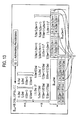
- each element C in Fig. 13 is either a covariance value between different resource elements of an SFBC pair or is a covariance value between different resource elements of the SFBC pair at different receiving antennas.
- the element C cannot be obtained by the CRS-based estimation method for the covariance matrix R I+N .
- the present invention has been made in view of the above problems, and has an objective of providing a receiver capable of performing appropriate reception processing by using a CRS-based estimation method for the covariance matrix R I+N .
- a first feature of the present invention is summarized as a receiver configured to receive a data signal, a control signal, and a cell-specific reference signal transmitted using a space frequency block coding scheme, the receiver including: a covariance matrix estimation unit configured to estimate a covariance matrix based on the cell-specific reference signal; a missing element insertion unit configured to insert a given value into an inestimable element in an interference-signal covariance matrix of interference signal components contained in the estimated covariance matrix; a reception weight generation unit configured to generate a reception weight by using the control signal and the covariance matrix having the given value inserted thereinto; and a signal separation unit configured to separate the data signal from a received signal by using the control signal and the generated reception weight.
- an IRC receiver 10 according to a first embodiment of the present invention is described.
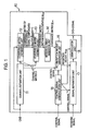
- the IRC receiver 10 includes a channel estimation unit 11, a covariance matrix estimation unit 12, a covariance matrix estimation unit 13, a missing element insertion unit 14, a control signal demodulation unit 15, an IRC reception weight generation unit 16, a signal separation unit 17, and a demodulation unit 18.
- the channel estimation unit 11 is configured to estimate (calculate) a channel matrix H by performing channel estimation processing based on CRSs received from a serving cell (a cell 1) .
- the covariance matrix estimation unit 12 is configured to estimate (calculate) an interference signal component covariance matrix: R ⁇ I + N based on the CRSs received from the serving cell (cell 1) and the channel matrix H received from the channel estimation 11.
- the covariance matrix estimation unit 13 is configured to estimate (calculate) a covariance matrix R I+N based on the channel matrix H received from the channel estimation unit 11 and the interference signal component covariance matrix: R ⁇ I + N received from the covariance matrix estimation unit 12, as shown in Fig. 2(a) .
- Each element D (missing element) shown in Fig. 2 (a) is, as described earlier, either a covariance value between different resource elements of an SFBC pair or a covariance value between different resource elements of the SFBC pair at different receiving antennas.
- the element D cannot be obtained by the CRS-based estimation method for the covariance matrix R I+N .
- the elements D do not contain a desired signal component from the serving cell (cell 1), all the values of the element D are supposedly small values.
- the missing element insertion unit 14 is, as shown in Fig. 2(b) , configured to insert a fixed value "0" as a given value, into all the elements D in the covariance matrix R I+N received from the covariance matrix estimation unit 13.
- the control signal demodulation unit 15 is configured to perform demodulation processing on a control signal received from the serving cell (cell 1).
- the IRC reception weight generation unit 16 is configured to generate an IRC reception weight W IRC based on the channel matrix H received from the channel estimation unit 11, the control signal received from the control signal demodulation unit 15, and the covariance matrix R I+N received from the missing element insertion unit 14 (the covariance matrix R I+N having "0" inserted into the elements D).
- the IRC reception weight generation unit 16 is configured to generate the IRC reception weight W IRC by assigning the channel matrix H received from the channel estimation unit 11 and the covariance matrix R I+N received from the missing element insertion unit 14 to the formula shown in Fig. 11(a) .
- the signal separation unit 17 is configured to perform signal separation processing on a received signal from the serving cell (cell 1), based on the control signal received from the control signal demodulation unit 15 and the IRC reception weight W IRC received from the IRC reception weight generation unit 16.
- the demodulation unit 18 is configured to output a data signal by performing demodulation processing on a signal received from the signal separation unit 17, based on the control signal received from the control signal demodulation unit 15 and the IRC reception weight W IRC received from the IRC reception weight generation unit 16.
- the fixed value "0" is inserted as a given value into an inestimable element in the interference-signal covariance matrix: R ⁇ I + N .
- an IRC receiver 10 according to Modification 1 of the present invention is described.
- the IRC receiver 10 according to Modification 1 is described below, with a focus on differences from the IRC receiver 10 according to the first embodiment.
- the IRC receiver 10 includes a missing element calculation unit 21 in addition to the configuration shown in Fig. 1 .
- the missing element calculation unit 21 is configured to calculate a given value to be inserted into each inestimable element D in the interference-signal covariance matrix: R ⁇ I + N .
- the missing element insertion unit 14 may be configured to insert ⁇ , ⁇ *, - ⁇ , or - ⁇ * received from the missing element calculation unit 21 as a given value into each element D1 in the covariance matrix R I+N received from the covariance matrix estimation unit 13.
- the missing element insertion unit 14 may be configured to insert any one of ⁇ , ⁇ *, - ⁇ , or - ⁇ * received from the missing element calculation unit 21 or "0" as a given value into each element D2 in the covariance matrix R I+N received from the covariance matrix estimation unit 13.
- the missing element insertion unit 14 may be configured to insert a given value ⁇ or ⁇ * into each element D2 in the covariance matrix R I+N received from the covariance matrix estimation unit 13.
- the missing element insertion unit 14 may be configured to insert any one of ⁇ , ⁇ *, - ⁇ , or - ⁇ * received from the missing element calculation unit 21 or "0" as a given value into each element D1 in the covariance matrix R I+N received from the covariance matrix estimation unit 13.
- any one of ⁇ , ⁇ *, - ⁇ , or - ⁇ * is inserted as a given value into an inestimable element in the interference-signal covariance matrix: R ⁇ I + N .
- an IRC receiver 10 according to Modification 2 of the present invention is described.
- the IRC receiver 10 according to Modification 2 is described below, with a focus on differences from the IRC receiver 10 according to the first embodiment.
- the IRC receiver 10 includes a data-signal covariance matrix estimation unit 22 in addition to the configurations shown in Figs. 1 and 3 .
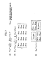
- the data-signal covariance matrix estimation unit 22 is configured to estimate the covariance matrix R I+N based on a received data signal according to Fig. 7(a) .
- the data-signal covariance matrix estimation unit 22 is configured to estimate a data-signal covariance matrix R' I+N according to Fig. 7(b) by using the channel matrix H estimated by the channel estimation unit 11 and the covariance matrix R I+N estimated by the covariance matrix estimation unit 22.
- the missing element calculation unit 21 is configured to calculate a given value to be inserted into the inestimable element D in the data-signal covariance matrix R' I+N described above.
- the missing element insertion unit 14 is, as shown in Fig. 7 (c) , configured to insert a corresponding element in the data-signal covariance matrix R' I+N received from the missing element calculation unit 21, to each element D in the covariance matrix R I+N received from the covariance matrix estimation unit 13, i.e., the elements D in Fig. 2(a) .
- a value of a corresponding element in a covariance matrix estimated by other method e.g., the data-signal covariance matrix R' I+N
- R I+N the data-signal covariance matrix
- the present invention can be implemented irrespective of the number of antennas of the IRC receiver 10.
- a first aspect of the present embodiment is summarized as an IRC receiver 10 configured to receive a data signal, a control signal, and a CRS (cell-specific reference signal) transmitted using an SFBC scheme, the IRC receiver 10 including: a covariance matrix estimation unit 12/13 configured to estimate a covariance matrix R I+N based on the CRS; a missing element insertion unit 14 configured to insert a given value into an inestimable element D in an interference-signal covariance matrix: R ⁇ I + N of interference signal components contained in the estimated covariance matrix R I+N ; an IRS reception weight generation unit 16 configured to generate an IRC reception weight W IRC by using the control signal and the covariance matrix R I+N having the given value inserted thereinto; and a signal separation unit 17 configured to separate the data signal from a received signal by using the generated IRC reception weight and the control signal.
- a covariance matrix estimation unit 12/13 configured to estimate a covariance matrix R I+N based on the CRS
- the missing element insertion unit 14 may be configured to insert a fixed value "0" as the given value.
- the missing element insertion unit 14 may be configured to insert, as the given value, a value ⁇ , ⁇ *, - ⁇ , or - ⁇ * calculated based on an estimable element in the interference-signal covariance matrix: R ⁇ I + N .
- the IRC receiver 10 may further include a data-signal covariance matrix estimation unit 22 configured to estimate a covariance matrix: R I + N ⁇ based on the data signal received, and the missing element insertion unit 21 may be configured to insert, as the given value, a corresponding element in the covariance matrix: R I + N ⁇ estimated by the data-signal covariance matrix estimation unit 22 into each element D in the covariance matrix R I+N received from the covariance matrix estimation unit 13.
- a data-signal covariance matrix estimation unit 22 configured to estimate a covariance matrix: R I + N ⁇ based on the data signal received
- the missing element insertion unit 21 may be configured to insert, as the given value, a corresponding element in the covariance matrix: R I + N ⁇ estimated by the data-signal covariance matrix estimation unit 22 into each element D in the covariance matrix R I+N received from the covariance matrix estimation unit 13.
- IRC receiver 10 may be implemented by hardware, may be implemented by a software module executed by a processor, or may be implemented in combination of the two.
- the software module may be provided in a storage medium in any format, such as a RAM (Random Access Memory), a flash memory, a ROM (Read Only Memory), an EPROM (Erasable Programmable ROM), an EEPROM (Electronically Erasable and Programmable ROM), a register, a hard disk, a removable disk, or CD-ROM.
- RAM Random Access Memory
- flash memory a ROM (Read Only Memory)
- EPROM Erasable Programmable ROM
- EEPROM Electrically Erasable and Programmable ROM
- register a hard disk, a removable disk, or CD-ROM.
- the storage medium is connected to a processor so that the processor can read and write information from and to the storage medium.
- the storage medium may be integrated in a processor.
- the storage medium and the processor may be provided inside an ASIC. Such an ASIC may be provided in the IRC receiver 10. Otherwise, the storage medium and the processor may be provided as discrete components inside the IRC receiver 10.
- the present invention can provide a receiver capable of performing appropriate reception processing by using a CRS-based estimation method for a covariance matrix R I+N .
Landscapes
- Engineering & Computer Science (AREA)
- Computer Networks & Wireless Communication (AREA)
- Signal Processing (AREA)
- Power Engineering (AREA)
- Radio Transmission System (AREA)
- Noise Elimination (AREA)
Abstract
Appropriate reception processing is performed using a CRS-based estimation method for a covariance matrix RI+N. An IRC receiver 10 according to the present invention includes: a covariance matrix estimation unit 12/13 configured to estimate a covariance matrix RI+N based on a CRS; a missing element insertion unit 14 configured to insert a given value into an inestimable element in an interference-signal covariance matrix RI+N ("∼" is on R) of interference signal components contained in the estimated covariance matrix RI+N; an IRC reception weight generation unit 16 configured to generate an IRC reception weight WIRC by using the control signal and the covariance matrix RI+N having the given value inserted thereinto; and a signal separation unit 17 configured to separate the data signal from a received signal by using the generated reception weight and the control signal.
Description
- The present invention relates to a receiver.
- In LTE (Long Term Evolution), an IRC (Interference Rejection Combining) receiver configured to suppress interfering beams of other mobile stations UE is discussed as one of methods for improving cell-edge throughput in downlink.
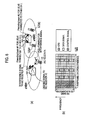
- As shown in
Fig. 8(a) , anIRC receiver 10 aims to improve the received quality of a desired signal by suppressing interference signals. - Further, LTE (Release-8) is configured such that a CRS (Cell-Specific Reference Signal) is transmitted to perform estimation of a channel state (CSI: Channel State Information), demodulation of data signals and control signals, and measurement of received quality in a cell.
- More specifically, LTE (Release-8) is configured such that the CRSs are transmitted along with data signals and control signals in a format shown in
Fig. 8(b) . Note that the CRS can be set for up to four antennas. - Further, LTE is configured to use an SFBC (Space Frequency Block Coding) scheme as a transmission diversity scheme.
- The SFBC scheme is configured to use "Alamouti coding" which can achieve the maximum diversity gain at a symbol level equivalent to maximum ratio combining. Specifically, the SFBC scheme is configured to perform coding by using two resource elements (RE) in a frequency direction. These two resource elements are referred to as an "SFBC pair" herein.
- A description is given below of a reception signal model for the
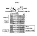
IRC receiver 10 in a case where, as shown inFig. 9 , theIRC receiver 10 receives a desired signal from a cell 1 (q=1) and receives an interference signal from a cell 2 (q=2), the model ignoring channel fluctuations. - Specifically, formulae shown in
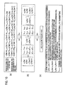
Figs. 10(a) to 10(c) can express a reception signal r1 (2m) by a receiving antenna 1 (i=1) of theIRC receiver 10 in the even-numbered resource element of an SFBC pair m, a reception signal r2 (2m) by a receiving antenna 2 (i=2) of theIRC receiver 10 in the even-numbered resource element of the SFBC pair m, a reception signal r1* (2m+1) by the receiving antenna 1 (i=1) of theIRC receiver 10 in the odd-numbered resource element of the SFBC pair m, and a reception signal r2* (2m+1) by the receiving antenna 2 (i=2) of theIRC receiver 10 in the odd-numbered resource element of the SFBC pair m. Note that * denotes a complex conjugate. - Meanwhile, a technique for performing reception processing by using an MMSE (Minimum Mean Square Error) spatial filtering scheme is conventionally known for interference suppression.
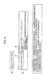
- This technique is configured to generate an IRC reception weight WIRC (k,l), as shown in
Fig. 11(a) . To generate the IRC reception weight WIRC (k,l), a CRS-based estimation method for a covariance matrix RI+N shown inFig. 11(b) is used (see - Non-patent document 1).
- As shown in
Fig. 11(b) , the covariance matrix RI+N includes a desired-signal covariance matrix A of desired signal components and an interference-signal covariance matrix B of interference signal components (noise signal components). Hereinbelow, the interference-signal covariance matrix B is expressed as:
- Non-patent document 1: 3GPP contribution R4-115213
- However, as shown in
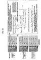
Fig. 12 , based on the CRSs transmitted in a serving cell (cell 1), theIRC receiver 10 can extract only interference from the even-numbered resource element of the SFBC pair in aninterference cell # 1/#2, i.e., cannot extract solely interference from the odd-numbered resource element of the SFBC pair in theinterference cell # 1/#2. - Specifically, an interference-signal-component covariance matrix for the even-numbered resource element of the SFBC pair is expressed by Formula (1) shown in
Fig. 12 as:
Fig. 12 as:
- Then, by using Formulae (1) and (2) shown in
Fig. 12 , an interference-signal-component covariance matrix is expressed as:
Fig. 13 . In such a case, each element C inFig. 13 is either a covariance value between different resource elements of an SFBC pair or is a covariance value between different resource elements of the SFBC pair at different receiving antennas. Thus, the element C cannot be obtained by the CRS-based estimation method for the covariance matrix RI+N. - This problem leads to a problem where the IRC reception weight cannot be appropriately generated, hindering appropriate reception processing.
- The present invention has been made in view of the above problems, and has an objective of providing a receiver capable of performing appropriate reception processing by using a CRS-based estimation method for the covariance matrix RI+N.
- A first feature of the present invention is summarized as a receiver configured to receive a data signal, a control signal, and a cell-specific reference signal transmitted using a space frequency block coding scheme, the receiver including: a covariance matrix estimation unit configured to estimate a covariance matrix based on the cell-specific reference signal; a missing element insertion unit configured to insert a given value into an inestimable element in an interference-signal covariance matrix of interference signal components contained in the estimated covariance matrix; a reception weight generation unit configured to generate a reception weight by using the control signal and the covariance matrix having the given value inserted thereinto; and a signal separation unit configured to separate the data signal from a received signal by using the control signal and the generated reception weight.
-
- [
Fig. 1] Fig. 1 is a functional block diagram of an IRC receiver according to a first embodiment of the present invention. - [
Fig. 2] Fig. 2 is a diagram illustrating a method for calculating a covariance matrix, by the IRC receiver according to the first embodiment of the present invention. - [
Fig. 3] Fig. 3 is a functional block diagram of an IRC receiver according toModification 1 of the present invention. - [
Fig. 4] Fig. 4 is a diagram illustrating a method for calculating a covariance matrix, by the IRC receiver according toModification 1 of the present invention. - [
Fig. 5] Fig. 5 is a diagram illustrating a method for calculating a covariance matrix, by the IRC receiver according toModification 1 of the present invention. - [
Fig. 6] Fig. 6 is a functional block diagram of an IRC receiver according toModification 2 of the present invention. - [
Fig. 7] Fig. 7 is a diagram illustrating a method for calculating a covariance matrix, by the IRC receiver according toModification 2 of the present invention. - [
Fig. 8] Fig. 8 is a diagram illustrating a prior art. - [
Fig. 9] Fig. 9 is a diagram illustrating a prior art. - [
Fig. 10] Fig. 10 is a diagram illustrating a prior art. - [
Fig. 11] Fig. 11 is a diagram illustrating a prior art. - [
Fig. 12] Fig. 12 is a diagram illustrating a prior art. - [
Fig. 13] Fig. 13 is a diagram illustrating a prior art. - With reference to
Figs. 1 and2 , anIRC receiver 10 according to a first embodiment of the present invention is described. - As shown in
Fig. 1 , theIRC receiver 10 according to the present embodiment includes achannel estimation unit 11, a covariancematrix estimation unit 12, a covariancematrix estimation unit 13, a missingelement insertion unit 14, a controlsignal demodulation unit 15, an IRC receptionweight generation unit 16, asignal separation unit 17, and ademodulation unit 18. - The
channel estimation unit 11 is configured to estimate (calculate) a channel matrix H by performing channel estimation processing based on CRSs received from a serving cell (a cell 1) . - The covariance
matrix estimation unit 12 is configured to estimate (calculate) an interference signal component covariance matrix:
channel estimation 11. - The covariance
matrix estimation unit 13 is configured to estimate (calculate) a covariance matrix RI+N based on the channel matrix H received from thechannel estimation unit 11 and the interference signal component covariance matrix:
matrix estimation unit 12, as shown inFig. 2(a) . - Each element D (missing element) shown in
Fig. 2 (a) is, as described earlier, either a covariance value between different resource elements of an SFBC pair or a covariance value between different resource elements of the SFBC pair at different receiving antennas. Thus, the element D cannot be obtained by the CRS-based estimation method for the covariance matrix RI+N. - However, since the elements D do not contain a desired signal component from the serving cell (cell 1), all the values of the element D are supposedly small values.
- Thus, the missing
element insertion unit 14 is, as shown inFig. 2(b) , configured to insert a fixed value "0" as a given value, into all the elements D in the covariance matrix RI+N received from the covariancematrix estimation unit 13. - The control
signal demodulation unit 15 is configured to perform demodulation processing on a control signal received from the serving cell (cell 1). - The IRC reception
weight generation unit 16 is configured to generate an IRC reception weight WIRC based on the channel matrix H received from thechannel estimation unit 11, the control signal received from the controlsignal demodulation unit 15, and the covariance matrix RI+N received from the missing element insertion unit 14 (the covariance matrix RI+N having "0" inserted into the elements D). - Specifically, the IRC reception
weight generation unit 16 is configured to generate the IRC reception weight WIRC by assigning the channel matrix H received from thechannel estimation unit 11 and the covariance matrix RI+N received from the missingelement insertion unit 14 to the formula shown inFig. 11(a) . - The
signal separation unit 17 is configured to perform signal separation processing on a received signal from the serving cell (cell 1), based on the control signal received from the controlsignal demodulation unit 15 and the IRC reception weight WIRC received from the IRC receptionweight generation unit 16. - The
demodulation unit 18 is configured to output a data signal by performing demodulation processing on a signal received from thesignal separation unit 17, based on the control signal received from the controlsignal demodulation unit 15 and the IRC reception weight WIRC received from the IRC receptionweight generation unit 16. - In the mobile communication system according to the present embodiment, the fixed value "0" is inserted as a given value into an inestimable element in the interference-signal covariance matrix:

- Thus, appropriate reception processing can be performed by use of the CRS-based estimation method for the covariance matrix RI+N.
- With reference to
Figs. 3 to 5 , anIRC receiver 10 according toModification 1 of the present invention is described. TheIRC receiver 10 according toModification 1 is described below, with a focus on differences from theIRC receiver 10 according to the first embodiment. - As shown in
Fig. 3 , theIRC receiver 10 according toModification 1 includes a missingelement calculation unit 21 in addition to the configuration shown inFig. 1 . - The missing
element calculation unit 21 is configured to calculate a given value to be inserted into each inestimable element D in the interference-signal covariance matrix:
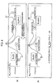
- For example, focusing on that an element D1 in the element D can be expressed as a single parameter x as shown in
Fig. 4(a) , the missingelement calculation unit 21 may be configured to use Formula (3) shown inFig. 4(b) to calculate a given value α (=x) to be inserted into the element D1. Specifically, the missingelement calculation unit 21 may be configured to calculate the given value α (=x) to be inserted into the element D1 by using an element of an off-diagonal term in the calculated interference-signal covariance matrix:
- Alternatively, focusing on that an element D2 in the element D can be expressed as two parameters y/z as shown in
Fig. 5(a) , the missingelement calculation unit 21 may be configured to use Formula (3) shown inFig. 5(b) to calculate the given value α (=y=z). Specifically, the missingelement calculation unit 21 may be configured to calculate the given value α (=y=Z) to be inserted into the element D2 by using an element of an off-diagonal term in the calculated interference-signal covariance matrix:
- As shown in
Fig. 4(b) , the missingelement insertion unit 14 may be configured to insert α, α*, -α, or -α* received from the missingelement calculation unit 21 as a given value into each element D1 in the covariance matrix RI+N received from the covariancematrix estimation unit 13. - In this regard, the missing
element insertion unit 14 may be configured to insert any one of α, α*, -α, or -α* received from the missingelement calculation unit 21 or "0" as a given value into each element D2 in the covariance matrix RI+N received from the covariancematrix estimation unit 13. - Alternatively, as shown in
Fig. 5 (b) , the missingelement insertion unit 14 may be configured to insert a given value α or α* into each element D2 in the covariance matrix RI+N received from the covariancematrix estimation unit 13. - In this regard, the missing
element insertion unit 14 may be configured to insert any one of α, α*, -α, or -α* received from the missingelement calculation unit 21 or "0" as a given value into each element D1 in the covariance matrix RI+N received from the covariancematrix estimation unit 13. - In the mobile communication system according to
Modification 1, any one of α, α*, -α, or -α* is inserted as a given value into an inestimable element in the interference-signal covariance matrix:
- Thereby, appropriate reception processing can be performed using the CRS-based estimation method for the covariance matrix RI+N.
- With reference to
Figs. 6 and7 , anIRC receiver 10 according toModification 2 of the present invention is described. TheIRC receiver 10 according toModification 2 is described below, with a focus on differences from theIRC receiver 10 according to the first embodiment. - As shown in
Fig. 6 , theIRC receiver 10 according toModification 2 includes a data-signal covariancematrix estimation unit 22 in addition to the configurations shown inFigs. 1 and3 . - The data-signal covariance
matrix estimation unit 22 is configured to estimate the covariance matrix RI+N based on a received data signal according toFig. 7(a) . - Specifically, the data-signal covariance
matrix estimation unit 22 is configured to estimate a data-signal covariance matrix R'I+N according toFig. 7(b) by using the channel matrix H estimated by thechannel estimation unit 11 and the covariance matrix RI+N estimated by the covariancematrix estimation unit 22. - In this regard, the missing
element calculation unit 21 is configured to calculate a given value to be inserted into the inestimable element D in the data-signal covariance matrix R'I+N described above. - The missing
element insertion unit 14 is, as shown inFig. 7 (c) , configured to insert a corresponding element in the data-signal covariance matrix R'I+N received from the missingelement calculation unit 21, to each element D in the covariance matrix RI+N received from the covariancematrix estimation unit 13, i.e., the elements D inFig. 2(a) . - In this way, a value of a corresponding element in a covariance matrix estimated by other method (e.g., the data-signal covariance matrix R'I+N) is inserted into an inestimable element in the covariance matrix RI+N. Thereby, appropriate reception processing can be performed using the CRS-based estimation method for the covariance matrix RI+N.
- Although the number of antennas of the
IRC receiver 10 is "two" in the above embodiment as an example, the present invention can be implemented irrespective of the number of antennas of theIRC receiver 10. - Aspects of the present embodiment described above may be expressed as follows.
- A first aspect of the present embodiment is summarized as an
IRC receiver 10 configured to receive a data signal, a control signal, and a CRS (cell-specific reference signal) transmitted using an SFBC scheme, theIRC receiver 10 including: a covariancematrix estimation unit 12/13 configured to estimate a covariance matrix RI+N based on the CRS; a missingelement insertion unit 14 configured to insert a given value into an inestimable element D in an interference-signal covariance matrix:
weight generation unit 16 configured to generate an IRC reception weight WIRC by using the control signal and the covariance matrix RI+N having the given value inserted thereinto; and asignal separation unit 17 configured to separate the data signal from a received signal by using the generated IRC reception weight and the control signal. - In the first aspect of the present embodiment, the missing
element insertion unit 14 may be configured to insert a fixed value "0" as the given value. - In the first aspect of the present embodiment, the missing
element insertion unit 14 may be configured to insert, as the given value, a value α, α*, -α, or -α* calculated based on an estimable element in the interference-signal covariance matrix:
- In the first aspect of the present embodiment, the
IRC receiver 10 may further include a data-signal covariancematrix estimation unit 22 configured to estimate a covariance matrix:
based on the data signal received, and the missingelement insertion unit 21 may be configured to insert, as the given value, a corresponding element in the covariance matrix:
estimated by the data-signal covariancematrix estimation unit 22 into each element D in the covariance matrix RI+N received from the covariancematrix estimation unit 13. - It should be noted that the foregoing operations of the
IRC receiver 10 may be implemented by hardware, may be implemented by a software module executed by a processor, or may be implemented in combination of the two. - The software module may be provided in a storage medium in any format, such as a RAM (Random Access Memory), a flash memory, a ROM (Read Only Memory), an EPROM (Erasable Programmable ROM), an EEPROM (Electronically Erasable and Programmable ROM), a register, a hard disk, a removable disk, or CD-ROM.
- The storage medium is connected to a processor so that the processor can read and write information from and to the storage medium. Instead, the storage medium may be integrated in a processor. The storage medium and the processor may be provided inside an ASIC. Such an ASIC may be provided in the
IRC receiver 10. Otherwise, the storage medium and the processor may be provided as discrete components inside theIRC receiver 10. - Hereinabove, the present invention has been described in detail by use of the foregoing embodiments. However, it is apparent to those skilled in the art that the present invention should not be limited to the embodiments described in the specification. The present invention can be implemented as an altered or modified embodiment without departing from the spirit and scope of the present invention, which are determined by the description of the scope of claims. Therefore, the description of the specification is intended for illustrative explanation only and does not impose any limited interpretation on the present invention.
- Note that the entire content of Japanese Patent Application No.
2011-242917 (filed on November 4, 2011 - As described above, the present invention can provide a receiver capable of performing appropriate reception processing by using a CRS-based estimation method for a covariance matrix RI+N.
-
- 10
- IRC receiver
- 11
- channel estimation unit
- 12, 13
- covariance matrix estimation unit
- 14
- missing element insertion unit
- 15
- control signal demodulation unit
- 16
- IRC reception weight generation unit
- 17
- signal separation unit
- 18
- demodulation unit
- 21
- missing element calculation unit
- 22
- data-signal covariance matrix estimation unit
Claims (4)
- A receiver configured to receive a data signal, a control signal, and a cell-specific reference signal transmitted using a space frequency block coding scheme, the receiver comprising:a covariance matrix estimation unit configured to estimate a covariance matrix based on the cell-specific reference signal;a missing element insertion unit configured to insert a given value into an inestimable element in an interference-signal covariance matrix of interference signal components contained in the estimated covariance matrix;a reception weight generation unit configured to generate a reception weight by using the control signal and the covariance matrix having the given value inserted thereinto; anda signal separation unit configured to separate the data signal from a received signal by using the control signal and the generated reception weight.
- The receiver according to claim 1, wherein
the missing element insertion unit is configured to insert a fixed value "0" as the given value. - The receiver according to claim 1, wherein
the missing element insertion unit is configured to insert, as the given value, a value calculated based on an estimable element in the interference-signal covariance matrix. - The receiver according to claim 1, further comprising
a data-signal covariance matrix estimation unit configured to estimate a covariance matrix based on the data signal received, wherein
the missing element insertion unit is configured to insert, as the given value, a corresponding element in the covariance matrix estimated by the data-signal covariance matrix estimation unit.
Applications Claiming Priority (2)
| Application Number | Priority Date | Filing Date | Title |
|---|---|---|---|
| JP2011242917A JP5816525B2 (en) | 2011-11-04 | 2011-11-04 | Receiver |
| PCT/JP2012/078471 WO2013065822A1 (en) | 2011-11-04 | 2012-11-02 | Receiver |
Publications (1)
| Publication Number | Publication Date |
|---|---|
| EP2775645A1 true EP2775645A1 (en) | 2014-09-10 |
Family
ID=48192159
Family Applications (1)
| Application Number | Title | Priority Date | Filing Date |
|---|---|---|---|
| EP12845078.0A Withdrawn EP2775645A1 (en) | 2011-11-04 | 2012-11-02 | Receiver |
Country Status (4)
| Country | Link |
|---|---|
| US (1) | US20140294125A1 (en) |
| EP (1) | EP2775645A1 (en) |
| JP (1) | JP5816525B2 (en) |
| WO (1) | WO2013065822A1 (en) |
Families Citing this family (5)
| Publication number | Priority date | Publication date | Assignee | Title |
|---|---|---|---|---|
| US9461757B2 (en) * | 2013-06-26 | 2016-10-04 | Intel IP Corporation | Method and device for processing a signal based on a first and a second covariance measure |
| JP2015201804A (en) * | 2014-04-10 | 2015-11-12 | 富士通株式会社 | Reception device, reception method, transmission device, transmission method, and wireless communication system |
| US11025399B2 (en) * | 2019-05-02 | 2021-06-01 | Nokia Technologies Oy | Interference suppression |
| US11949473B2 (en) | 2019-07-08 | 2024-04-02 | Nec Corporation | Wireless receiving apparatus, wireless communication system, and wireless receiving method |
| CN113347702B (en) * | 2020-02-18 | 2023-06-27 | 上海华为技术有限公司 | Interference source positioning method and related equipment |
Family Cites Families (3)
| Publication number | Priority date | Publication date | Assignee | Title |
|---|---|---|---|---|
| US8275074B2 (en) * | 2009-02-17 | 2012-09-25 | Telefonaktiebolaget Lm Ericsson (Publ) | OFDM receiver for dispersive environment |
| WO2012057666A1 (en) * | 2010-10-29 | 2012-05-03 | Telefonaktiebolaget Lm Ericsson (Publ) | Method and arrangement for interference mitigation |
| US8948323B2 (en) * | 2011-10-06 | 2015-02-03 | Telefonaktiebolaget L M Ericsson (Publ) | Method and device for suppressing interference in communication networks using frequency switched transmit diversity coding |
-
2011
- 2011-11-04 JP JP2011242917A patent/JP5816525B2/en not_active Expired - Fee Related
-
2012
- 2012-11-02 WO PCT/JP2012/078471 patent/WO2013065822A1/en not_active Ceased
- 2012-11-02 EP EP12845078.0A patent/EP2775645A1/en not_active Withdrawn
- 2012-11-02 US US14/353,931 patent/US20140294125A1/en not_active Abandoned
Non-Patent Citations (1)
| Title |
|---|
| See references of WO2013065822A1 * |
Also Published As
| Publication number | Publication date |
|---|---|
| JP5816525B2 (en) | 2015-11-18 |
| WO2013065822A1 (en) | 2013-05-10 |
| JP2013098943A (en) | 2013-05-20 |
| US20140294125A1 (en) | 2014-10-02 |
Similar Documents
| Publication | Publication Date | Title |
|---|---|---|
| EP2761770B1 (en) | Joint transmission in a wireless network | |
| EP3031145B1 (en) | Cooperative multiple beam transmission | |
| EP3261308B1 (en) | Interference rejection combining method, device and storage medium | |
| KR101636029B1 (en) | Method and apparatus of beamforming for using rate splitting scheme in mimo interference channel | |
| TWI504184B (en) | Mobile device searching using multiple antennas | |
| EP2590340B1 (en) | Channel estimating method, apparatus and system | |
| EP2996377B1 (en) | Method and device for submitting signal quality measurement information | |
| US10911172B2 (en) | User apparatus, base station, interference reducing method and interference reducing control information notification method | |
| KR101857668B1 (en) | Method of processing reception signal using preprocessing filter of mimo receiver | |
| EP2775645A1 (en) | Receiver | |
| EP3142263B1 (en) | Method for reducing complexity of mimo receiver which shares preprocessing filter in a group unit by adaptively using covariance matrix | |
| EP2953403A1 (en) | User device, base station, interference reduction method, and interference reduction control information notification method | |
| US9814054B2 (en) | Base station, user apparatus and interference reduction method | |
| EP3114775B1 (en) | Method for processing received signal of mimo receiver | |
| EP3391601B1 (en) | Communication terminal and method for channel estimation | |
| EP2381587A1 (en) | Method and device for determining antenna cooperation set, method and device for determining base station cooperation set | |
| EP3117531B1 (en) | Method for processing received signal of mimo receiver | |
| KR20110025145A (en) | Communication method, relay device, terminal device and base station | |
| EP3136802B1 (en) | Pilot configuration method and apparatus | |
| WO2015170854A1 (en) | Method for processing received signal by forming re group in mimo receiver | |
| EP2775647A1 (en) | Receiver | |
| EP2775646A1 (en) | Receiver | |
| CN116321440B (en) | Interference elimination method, device, interfered station and readable storage medium | |
| EP3139528B1 (en) | Communication device and method for signal determination in radio communication | |
| CN108809395B (en) | Method and apparatus for vehicle communication |
Legal Events
| Date | Code | Title | Description |
|---|---|---|---|
| PUAI | Public reference made under article 153(3) epc to a published international application that has entered the european phase |
Free format text: ORIGINAL CODE: 0009012 |
|
| 17P | Request for examination filed |
Effective date: 20140515 |
|
| AK | Designated contracting states |
Kind code of ref document: A1 Designated state(s): AL AT BE BG CH CY CZ DE DK EE ES FI FR GB GR HR HU IE IS IT LI LT LU LV MC MK MT NL NO PL PT RO RS SE SI SK SM TR |
|
| STAA | Information on the status of an ep patent application or granted ep patent |
Free format text: STATUS: THE APPLICATION HAS BEEN WITHDRAWN |
|
| 18W | Application withdrawn |
Effective date: 20141209 |