EP2775553A1 - Separator and electrochemical device having same - Google Patents
Separator and electrochemical device having same Download PDFInfo
- Publication number
- EP2775553A1 EP2775553A1 EP12844795.0A EP12844795A EP2775553A1 EP 2775553 A1 EP2775553 A1 EP 2775553A1 EP 12844795 A EP12844795 A EP 12844795A EP 2775553 A1 EP2775553 A1 EP 2775553A1
- Authority
- EP
- European Patent Office
- Prior art keywords
- separator
- inorganic particles
- air permeability
- lithium
- porous substrate
- Prior art date
- Legal status (The legal status is an assumption and is not a legal conclusion. Google has not performed a legal analysis and makes no representation as to the accuracy of the status listed.)
- Ceased
Links
Images

Classifications
-
- H—ELECTRICITY
- H01—ELECTRIC ELEMENTS
- H01M—PROCESSES OR MEANS, e.g. BATTERIES, FOR THE DIRECT CONVERSION OF CHEMICAL ENERGY INTO ELECTRICAL ENERGY
- H01M50/00—Constructional details or processes of manufacture of the non-active parts of electrochemical cells other than fuel cells, e.g. hybrid cells
- H01M50/40—Separators; Membranes; Diaphragms; Spacing elements inside cells
- H01M50/409—Separators, membranes or diaphragms characterised by the material
- H01M50/446—Composite material consisting of a mixture of organic and inorganic materials
-
- H—ELECTRICITY
- H01—ELECTRIC ELEMENTS
- H01M—PROCESSES OR MEANS, e.g. BATTERIES, FOR THE DIRECT CONVERSION OF CHEMICAL ENERGY INTO ELECTRICAL ENERGY
- H01M10/00—Secondary cells; Manufacture thereof
- H01M10/05—Accumulators with non-aqueous electrolyte
- H01M10/058—Construction or manufacture
-
- H—ELECTRICITY
- H01—ELECTRIC ELEMENTS
- H01M—PROCESSES OR MEANS, e.g. BATTERIES, FOR THE DIRECT CONVERSION OF CHEMICAL ENERGY INTO ELECTRICAL ENERGY
- H01M50/00—Constructional details or processes of manufacture of the non-active parts of electrochemical cells other than fuel cells, e.g. hybrid cells
- H01M50/40—Separators; Membranes; Diaphragms; Spacing elements inside cells
- H01M50/409—Separators, membranes or diaphragms characterised by the material
- H01M50/411—Organic material
- H01M50/414—Synthetic resins, e.g. thermoplastics or thermosetting resins
-
- H—ELECTRICITY
- H01—ELECTRIC ELEMENTS
- H01M—PROCESSES OR MEANS, e.g. BATTERIES, FOR THE DIRECT CONVERSION OF CHEMICAL ENERGY INTO ELECTRICAL ENERGY
- H01M50/00—Constructional details or processes of manufacture of the non-active parts of electrochemical cells other than fuel cells, e.g. hybrid cells
- H01M50/40—Separators; Membranes; Diaphragms; Spacing elements inside cells
- H01M50/409—Separators, membranes or diaphragms characterised by the material
- H01M50/411—Organic material
- H01M50/414—Synthetic resins, e.g. thermoplastics or thermosetting resins
- H01M50/417—Polyolefins
-
- H—ELECTRICITY
- H01—ELECTRIC ELEMENTS
- H01M—PROCESSES OR MEANS, e.g. BATTERIES, FOR THE DIRECT CONVERSION OF CHEMICAL ENERGY INTO ELECTRICAL ENERGY
- H01M50/00—Constructional details or processes of manufacture of the non-active parts of electrochemical cells other than fuel cells, e.g. hybrid cells
- H01M50/40—Separators; Membranes; Diaphragms; Spacing elements inside cells
- H01M50/409—Separators, membranes or diaphragms characterised by the material
- H01M50/411—Organic material
- H01M50/414—Synthetic resins, e.g. thermoplastics or thermosetting resins
- H01M50/426—Fluorocarbon polymers
-
- H—ELECTRICITY
- H01—ELECTRIC ELEMENTS
- H01M—PROCESSES OR MEANS, e.g. BATTERIES, FOR THE DIRECT CONVERSION OF CHEMICAL ENERGY INTO ELECTRICAL ENERGY
- H01M50/00—Constructional details or processes of manufacture of the non-active parts of electrochemical cells other than fuel cells, e.g. hybrid cells
- H01M50/40—Separators; Membranes; Diaphragms; Spacing elements inside cells
- H01M50/409—Separators, membranes or diaphragms characterised by the material
- H01M50/431—Inorganic material
-
- H—ELECTRICITY
- H01—ELECTRIC ELEMENTS
- H01M—PROCESSES OR MEANS, e.g. BATTERIES, FOR THE DIRECT CONVERSION OF CHEMICAL ENERGY INTO ELECTRICAL ENERGY
- H01M50/00—Constructional details or processes of manufacture of the non-active parts of electrochemical cells other than fuel cells, e.g. hybrid cells
- H01M50/40—Separators; Membranes; Diaphragms; Spacing elements inside cells
- H01M50/409—Separators, membranes or diaphragms characterised by the material
- H01M50/443—Particulate material
-
- H—ELECTRICITY
- H01—ELECTRIC ELEMENTS
- H01M—PROCESSES OR MEANS, e.g. BATTERIES, FOR THE DIRECT CONVERSION OF CHEMICAL ENERGY INTO ELECTRICAL ENERGY
- H01M50/00—Constructional details or processes of manufacture of the non-active parts of electrochemical cells other than fuel cells, e.g. hybrid cells
- H01M50/40—Separators; Membranes; Diaphragms; Spacing elements inside cells
- H01M50/409—Separators, membranes or diaphragms characterised by the material
- H01M50/449—Separators, membranes or diaphragms characterised by the material having a layered structure
-
- H—ELECTRICITY
- H01—ELECTRIC ELEMENTS
- H01M—PROCESSES OR MEANS, e.g. BATTERIES, FOR THE DIRECT CONVERSION OF CHEMICAL ENERGY INTO ELECTRICAL ENERGY
- H01M50/00—Constructional details or processes of manufacture of the non-active parts of electrochemical cells other than fuel cells, e.g. hybrid cells
- H01M50/40—Separators; Membranes; Diaphragms; Spacing elements inside cells
- H01M50/409—Separators, membranes or diaphragms characterised by the material
- H01M50/449—Separators, membranes or diaphragms characterised by the material having a layered structure
- H01M50/451—Separators, membranes or diaphragms characterised by the material having a layered structure comprising layers of only organic material and layers containing inorganic material
-
- H—ELECTRICITY
- H01—ELECTRIC ELEMENTS
- H01M—PROCESSES OR MEANS, e.g. BATTERIES, FOR THE DIRECT CONVERSION OF CHEMICAL ENERGY INTO ELECTRICAL ENERGY
- H01M50/00—Constructional details or processes of manufacture of the non-active parts of electrochemical cells other than fuel cells, e.g. hybrid cells
- H01M50/40—Separators; Membranes; Diaphragms; Spacing elements inside cells
- H01M50/463—Separators, membranes or diaphragms characterised by their shape
-
- H—ELECTRICITY
- H01—ELECTRIC ELEMENTS
- H01M—PROCESSES OR MEANS, e.g. BATTERIES, FOR THE DIRECT CONVERSION OF CHEMICAL ENERGY INTO ELECTRICAL ENERGY
- H01M50/00—Constructional details or processes of manufacture of the non-active parts of electrochemical cells other than fuel cells, e.g. hybrid cells
- H01M50/40—Separators; Membranes; Diaphragms; Spacing elements inside cells
- H01M50/489—Separators, membranes, diaphragms or spacing elements inside the cells, characterised by their physical properties, e.g. swelling degree, hydrophilicity or shut down properties
-
- H—ELECTRICITY
- H01—ELECTRIC ELEMENTS
- H01M—PROCESSES OR MEANS, e.g. BATTERIES, FOR THE DIRECT CONVERSION OF CHEMICAL ENERGY INTO ELECTRICAL ENERGY
- H01M50/00—Constructional details or processes of manufacture of the non-active parts of electrochemical cells other than fuel cells, e.g. hybrid cells
- H01M50/40—Separators; Membranes; Diaphragms; Spacing elements inside cells
- H01M50/489—Separators, membranes, diaphragms or spacing elements inside the cells, characterised by their physical properties, e.g. swelling degree, hydrophilicity or shut down properties
- H01M50/491—Porosity
-
- H—ELECTRICITY
- H01—ELECTRIC ELEMENTS
- H01M—PROCESSES OR MEANS, e.g. BATTERIES, FOR THE DIRECT CONVERSION OF CHEMICAL ENERGY INTO ELECTRICAL ENERGY
- H01M10/00—Secondary cells; Manufacture thereof
- H01M10/05—Accumulators with non-aqueous electrolyte
- H01M10/052—Li-accumulators
-
- H—ELECTRICITY
- H01—ELECTRIC ELEMENTS
- H01M—PROCESSES OR MEANS, e.g. BATTERIES, FOR THE DIRECT CONVERSION OF CHEMICAL ENERGY INTO ELECTRICAL ENERGY
- H01M50/00—Constructional details or processes of manufacture of the non-active parts of electrochemical cells other than fuel cells, e.g. hybrid cells
- H01M50/40—Separators; Membranes; Diaphragms; Spacing elements inside cells
- H01M50/489—Separators, membranes, diaphragms or spacing elements inside the cells, characterised by their physical properties, e.g. swelling degree, hydrophilicity or shut down properties
- H01M50/497—Ionic conductivity
-
- Y—GENERAL TAGGING OF NEW TECHNOLOGICAL DEVELOPMENTS; GENERAL TAGGING OF CROSS-SECTIONAL TECHNOLOGIES SPANNING OVER SEVERAL SECTIONS OF THE IPC; TECHNICAL SUBJECTS COVERED BY FORMER USPC CROSS-REFERENCE ART COLLECTIONS [XRACs] AND DIGESTS
- Y02—TECHNOLOGIES OR APPLICATIONS FOR MITIGATION OR ADAPTATION AGAINST CLIMATE CHANGE
- Y02E—REDUCTION OF GREENHOUSE GAS [GHG] EMISSIONS, RELATED TO ENERGY GENERATION, TRANSMISSION OR DISTRIBUTION
- Y02E60/00—Enabling technologies; Technologies with a potential or indirect contribution to GHG emissions mitigation
- Y02E60/10—Energy storage using batteries
-
- Y—GENERAL TAGGING OF NEW TECHNOLOGICAL DEVELOPMENTS; GENERAL TAGGING OF CROSS-SECTIONAL TECHNOLOGIES SPANNING OVER SEVERAL SECTIONS OF THE IPC; TECHNICAL SUBJECTS COVERED BY FORMER USPC CROSS-REFERENCE ART COLLECTIONS [XRACs] AND DIGESTS
- Y02—TECHNOLOGIES OR APPLICATIONS FOR MITIGATION OR ADAPTATION AGAINST CLIMATE CHANGE
- Y02P—CLIMATE CHANGE MITIGATION TECHNOLOGIES IN THE PRODUCTION OR PROCESSING OF GOODS
- Y02P70/00—Climate change mitigation technologies in the production process for final industrial or consumer products
- Y02P70/50—Manufacturing or production processes characterised by the final manufactured product
-
- Y—GENERAL TAGGING OF NEW TECHNOLOGICAL DEVELOPMENTS; GENERAL TAGGING OF CROSS-SECTIONAL TECHNOLOGIES SPANNING OVER SEVERAL SECTIONS OF THE IPC; TECHNICAL SUBJECTS COVERED BY FORMER USPC CROSS-REFERENCE ART COLLECTIONS [XRACs] AND DIGESTS
- Y10—TECHNICAL SUBJECTS COVERED BY FORMER USPC
- Y10T—TECHNICAL SUBJECTS COVERED BY FORMER US CLASSIFICATION
- Y10T29/00—Metal working
- Y10T29/49—Method of mechanical manufacture
- Y10T29/49002—Electrical device making
- Y10T29/49108—Electric battery cell making
Definitions
- the present invention relates to a separator for an electrochemical device such as a lithium secondary battery, and an electrochemical device having the same. More particularly, the present invention relates to a separator having a porous coating layer comprising an organic-inorganic mixture, and an electrochemical device having the same.
- Electrochemical devices have been widely used as energy sources in the fields of cellular phones, camcorders, notebook computers, PCs and electric cars, resulting in intensive research and development into them.
- electrochemical devices are one of the subjects of great interest.
- development of rechargeable secondary batteries has been the focus of attention.
- research and development of such batteries are focused on the designs of new electrodes and batteries to improve capacity density and specific energy.
- Many secondary batteries are currently available.
- lithium secondary batteries developed in the early 1990's have drawn particular attention due to their advantages of higher operating voltages and much higher energy densities than conventional aqueous electrolyte-based batteries, for example, Ni-MH, Ni-Cd, and H 2 SO 4 -Pb batteries.
- such lithium ion batteries suffer from safety problems, such as fire and explosion, when encountered with the use of organic electrolytes and are disadvantageously complicated to fabricate.
- lithium ion polymer batteries have been developed as next-generation batteries. More research is still urgently needed to improve the relatively low capacities and insufficient low-temperature discharge capacities of lithium ion polymer batteries in comparison with lithium ion batteries.
- electrochemical devices with different safety characteristics. It is very important to evaluate and ensure the safety of such electrochemical devices. The most important consideration for safety is that operational failure or malfunction of electrochemical devices should not cause injury to users. For this purpose, regulatory guidelines strictly restrict potential dangers (such as fire and smoke emission) of electrochemical devices. Overheating of an electrochemical device may cause thermal runaway or a puncture of a separator may pose an increased risk of explosion.
- porous polyolefin substrates commonly used as separators for electrochemical devices undergo severe thermal shrinkage at a temperature of 100 °C or higher in view of their material characteristics and production processes including elongation. This thermal shrinkage behavior may cause a short circuit between a cathode and an anode.
- a separator comprising a highly porous substrate and a porous organic/inorganic coating layer formed by coating a mixture of an excess of inorganic particles and a binder polymer on at least one surface of the porous substrate. If the porous organic/inorganic coating layer is formed on the outer surface of the porous substrate for the purpose of safety, it is necessary to control the content ratio of the inorganic particles and the binder polymer or the thickness of the porous coating layer, depending on the properties of the porous substrate. However, there has been no specific basis for such a control.
- the present invention is designed to solve the problems of the prior art, and therefore it is an object of the present invention to provide a separator having a porous organic-inorganic coating layer satisfying an optimal condition for strengthening the safety of an electrochemical device.
- a separator comprising a porous substrate; and a porous coating layer formed on at least one surface of the porous substrate and comprising a mixture of inorganic particles and a binder polymer, which has a value of a porosity x an air permeability per thickness in the range of 5 to 40, the porosity and the air permeability per thickness being defined by Formula (I) and Formula (II), respectively:
- Porosity 1 - the weight ratio of the inorganic particles / the density of the inorganic particles + the weight ratio of the binder polymer / the density of the binder polymer
- Air Permeability per thickness the air permeabililty of the separator - the air permeability of the porous substrate / the thickness of the separator - the thickness of the porous substrate
- the porosity ranges from equal to or greater than 0.5 to less than 1, and the air permeability per thickness ranges from 5 to 80.
- the porous substrate may be made of a polyolefin-based polymer, but is not particularly limited thereto.
- the polyolefin-based polymer is preferably selected from polyethylene, polypropylene, polybutylene and polypentene.
- the inorganic particles used in the present invention may be inorganic particles having a dielectric constant of 5 or higher, inorganic particles having the ability to transport lithium ions, or a mixture thereof.
- Examples of the inorganic particles having a dielectric constant of 5 or higher include BaTiO 3 , Pb(Zr x ,Ti 1-x )O 3 (PZT, 0 ⁇ x ⁇ 1), Pb 1-x La x Zr 1-y Ti y O 3 (PLZT, 0 ⁇ x ⁇ 1, 0 ⁇ y ⁇ 1), (1-x)Pb(Mg 1/3 Nb 2/3 )O 3 -xPbTiO 3 (PMN-PT, 0 ⁇ x ⁇ 1), hafnia (HfO 2 ), SrTiO 3 , SnO 2 , CeO 2 , MgO, NiO, CaO, ZnO, ZrO 2 , SiO 2 , Y 2 O 3 , Al 2 O 3 , SiC, TiO 2 inorganic particles and a mixture thereof, but are not particularly limited thereto.
- examples of the inorganic particles having the ability to transport lithium ions include lithium phosphate (Li 3 PO 4 ), lithium titanium phosphate (Li x Ti y (PO 4 ) 3 , 0 ⁇ x ⁇ 2, 0 ⁇ y ⁇ 3), lithium aluminum titanium phosphate (Li x Al y Ti z (PO 4 ) 3 , 0 ⁇ x ⁇ 2, 0 ⁇ y ⁇ 1, 0 ⁇ z ⁇ 3), (LiAlTiP) x O y type glass (0 ⁇ x ⁇ 4, 0 ⁇ y ⁇ 13), lithium lanthanum titanate (Li x La y TiO 3 ,0 ⁇ x ⁇ 2, 0 ⁇ y ⁇ 3), lithium germanium thiophosphate (Li x Ge y P z S w , 0 ⁇ x ⁇ 4, 0 ⁇ y ⁇ 1, 0 ⁇ z ⁇ 1, 0 ⁇ w ⁇ 5), lithium nitride (Li x N y , 0 ⁇ x ⁇ 4, 0 ⁇ y ⁇ 2), SiS 2 type glass (Li x
- the binder polymer may be selected from the group consisting of polyvinylidene fluoride-co-hexafluoropropylene, polyvinylidene fluoride-cotrichloroethylene, polymethyl methacrylate, polybutyl acrylate, polyacrylonitrile, polyvinylpyrrolidone, polyvinyl acetate, polyvinyl alcohol, polyethylene-co-vinyl acetate, polyethylene oxide, polyarylate, cellulose acetate, cellulose acetate butyrate, cellulose acetate propionate, cyanoethylpullulan, cyanoethyl polyvinyl alcohol, cyanoethyl cellulose, cyanoethyl sucrose, pullulan, carboxymethyl cellulose, a low molecular compound having a molecular weight of 10,000 g/mol or less, and a mixture thereof, but are not limited thereto.
- the separator of the present invention may be used in an electrochemical device such as a lithium secondary battery and a super capacitor device.
- the separator having a porous coating layer according to the present invention has a porosity of the porous coating layer, which is controlled depending on the air permeability of the porous substrate, and thus exhibit superior ionic conductivity as well as good mechanical properties, thereby contributing to improve the performance and safety of an electrochemical device.
- the present invention provides a separator, comprising a porous substrate; and a porous coating layer formed on at least one surface of the porous substrate and comprising a mixture of inorganic particles and a binder polymer, which has a value of a porosity x an air permeability per thickness in the range of 5 to 40, the porosity and the air permeability per thickness being defined by Formula (I) and Formula (II), respectively:
- Porosity 1 - the weight ratio of the inorganic particles / the density of the inorganic particles + the weight ratio of the binder polymer / the density of the binder polymer
- Air Permeability per thickness the air permeabililty of the separator - the air permeability of the porous substrate / the thickness of the separator - the thickness of the porous substrate
- the terms 'the weight ratio of the inorganic particles' and 'the weight ratio of the binder polymer' refer to the weight of each of the inorganic particles and the binder polymer based on 100 parts by weight of the total weight of the inorganic particles and the binder polymer.
- the binder polymer allows the adhesion of the inorganic particles so that the inorganic particles can be bound with each other (i.e., the binder polymer connects and immobilizes the inorganic particles therebetween), and also, the inorganic particles are substantially present in contact with each other to form a closest packed structure, and an interstitial volume generated from the contact of the inorganic particles with each other becomes a pore of the porous coating layer.
- the separator comprising such a porous coating layer can maintain air permeability with improved thermal safety, due to the nature of the porous coating layer.
- the binder polymer functions to hinder ions from transferring to increase the resistance of the ions. Accordingly, the use of the binder polymer in an excessive amount may deteriorate the performance of an electrochemical device, while the use of the binder polymer in a small amount may cause the release of the inorganic particles to deteriorate mechanical properties. Therefore, it is important to control the amount of the binder.
- the air permeability of the porous substrate is actually reduced. Accordingly, it is necessary to define the air permeability range of the porous coating layer in a certain degree so that the performance of an electrochemical device is not excessively deteriorated. That is, it is preferred to control the properties of the porous coating layer taking into account the air permeability of the porous substrate to be used.
- a value of a porosity x an air permeability per thickness is in the range of 5 to 40, the porosity thereof can be controlled depending on the air permeability of the porous substrate, to allow the coating layer to have good mechanical properties and ionic conductivity, and eventually contribute to improve the performance and safety of an electrochemical device.
- a porosity ranges from equal to or greater than 0.5 to less than 1, and an air permeability per thickness ranges from 5 to 80, while satisfying a value of a porosity x an air permeability per thickness in the range of 5 to 40.
- porosity refers to the ratio of pore spaces occupied in a porous substance, i.e., a fraction of the volume of empty pores over the total volume in the substance.
- the porosity is represented by a value obtained by dividing the weight ratio of the inorganic particles and the binder polymer by each density.
- air permeability per thickness refers to a value obtained by dividing the difference between the air permeability of the separator and the air permeability of the porous substrate by the thickness of the porous layer (the thickness of the separator - the thickness of the porous substrate).
- the unit for the porosity is 'sec/100 ml', and the unit for the thickness of the porous coating layer is ' ⁇ m'.
- 'a porosity x an air permeability per thickness' is less than 5
- a space between the inorganic particles becomes overly broad, from which an inner short circuit on the infiltration of a foreign substance may occur to deteriorate safety.
- the value of 'a porosity x an air permeability per thickness' is greater than 40, passages capable of transporting lithium ions may be reduced to severely deteriorate ionic conductivity, and thus, the separator fails to be used in an electrochemical device.
- the porous substrate may be made of a polyolefin-based polymer.
- the polyolefin-based polymer is preferably selected from polyethylene, polypropylene, polybutylene and polypentene.
- the inorganic particles used in the present invention may be inorganic particles having a dielectric constant of 5 or higher, inorganic particles having the ability to transport lithium ions, or a mixture thereof.
- Non-limiting examples of the inorganic particles having a dielectric constant of 5 or higher include BaTiO 3 , Pb(Zr x ,Ti 1-x )O 3 (PZT, 0 ⁇ x ⁇ 1), Pb 1-x La x Zr 1-y Ti y O 3 (PLZT, 0 ⁇ x ⁇ 1, 0 ⁇ y ⁇ 1), (1-x)Pb(Mg 1/3 Nb 2/3 )O 3 -xPbTiO 3 (PMN-PT, 0 ⁇ x ⁇ 1), hafnia (HfO 2 ), SrTiO 3 , SnO 2 , CeO 2 , MgO, NiO, CaO, ZnO, ZrO 2 , SiO 2 , Y 2 O 3 , Al 2 O 3 , TiO 2 , SiC, inorganic particles and a mixture thereof.
- non-limiting examples of the inorganic particles having the ability to transport lithium ions include lithium phosphate (Li 3 PO 4 ), lithium titanium phosphate (Li x Ti y (PO 4 ) 3 , 0 ⁇ x ⁇ 2, 0 ⁇ y ⁇ 3), lithium aluminum titanium phosphate (Li x Al y Ti z (PO 4 ) 3 , 0 ⁇ x ⁇ 2, 0 ⁇ y ⁇ 1, 0 ⁇ z ⁇ 3), (LiAlTiP) x O y type glass (0 ⁇ x ⁇ 4, 0 ⁇ y ⁇ 13), lithium lanthanum titanate (Li x La y TiO 3 ,0 ⁇ x ⁇ 2, 0 ⁇ y ⁇ 3), lithium germanium thiophosphate (Li x Ge y P z S w , 0 ⁇ x ⁇ 4, 0 ⁇ y ⁇ 1, 0 ⁇ z ⁇ 1, 0 ⁇ w ⁇ 5), lithium nitride (Li x N y , 0 ⁇ x ⁇ 4, 0 ⁇ y ⁇ 2), SiS 2 type glass (
- the binder polymer may be any one selected from the group consisting of polyvinylidene fluoride-co-hexafluoropropylene, polyvinylidene fluoride-cotrichloroethylene, polymethyl methacrylate, polybutyl acrylate, polyacrylonitrile, polyvinylpyrrolidone, polyvinyl acetate, polyvinyl alcohol, polyethylene-co-vinyl acetate, polyethylene oxide, polyarylate, cellulose acetate, cellulose acetate butyrate, cellulose acetate propionate, cyanoethylpullulan, cyanoethyl polyvinyl alcohol, cyanoethyl cellulose, cyanoethyl sucrose, pullulan, carboxymethyl cellulose, a low molecular compound having a molecular weight of 10,000 g/mol or less, and a mixture thereof.
- the present invention provides an electrochemical device comprising a cathode, an anode, the above-mentioned separator which is interposed between the cathode and the anode, and an electrolyte solution.
- the cathode and the anode are not particularly limited, and may be manufactured by binding an electrode active material to an electrode current collector according to a conventional method known in the art.
- cathode active material those that are commonly used in cathodes of conventional electrochemical devices may be used.
- the cathode active material may be any one selected from the group consisting of LiCoO 2 , LiNiO 2 , LiMn 2 O 4 , LiCoPO 4 , LiFePO 4 , LiNiMnCoO 2 , LiNi 1-x-y-z Co x M1 y M2 z O 2 (wherein M1 and M2 are each independently selected from the group consisting of Al, Ni, Co, Fe, Mn, V, Cr, Ti, W, Ta, Mg and Mo, and x, y and z are each independently an atomic fraction of oxide-forming elements, in which 0 ⁇ x ⁇ 0.5, 0 ⁇ y ⁇ 0.5, 0 ⁇ z ⁇ 0.5, and x+y+z ⁇ 1).
- anode active material those that are commonly used in anodes of conventional electrochemical devices may be used, and non-limiting examples thereof include lithium, lithium alloys, and lithium intercalation materials such as carbon, petroleum coke, activated carbon, graphite and other carbonaceous materials.
- Non-limiting examples of a usable cathode current collector include aluminum foils, nickel foils and a combination thereof.
- Non-limiting examples of a usable anode current collector include copper foils, gold foils, nickel foils, copper alloy foils and a combination thereof.
- the electrolyte solution which may be used in the present invention is obtained by dissolving or dissociating a salt in an organic solvent.
- the salt has a structure represented by A + B - wherein A + is an alkali metal cation such as Li + , Na + , K + and a combination thereof and B - is an anion such as PF 6 - , BF 4 - , Cl - , Br - , I - , ClO 4 - , AsF 6 - , CH 3 CO 2 - , CF 3 SO 3 - , N(CF 3 SO 2 ) 2 - , C(CF 2 SO 2 ) 3 - and a combination thereof.
- organic solvent examples include propylene carbonate (PC), ethylene carbonate (EC), diethyl carbonate (DEC), dimethyl carbonate (DMC), dipropyl carbonate (DPC), dimethyl sulfoxide, acetonitrile, dimethoxyethane, diethoxyethane, tetrahydrofuran, N-methyl-2-pyrrolidone (NMP), ethyl methyl carbonate (EMC), ⁇ -butyrolactone and a mixture thereof, but are not limited thereto.
- the electrolyte solution may be introduced in any suitable step during the manufacturing of the electrochemical device depending on the manufacturing processes and desired physical properties of a final product. Specifically, the electrolyte may be introduced before assembling a battery or in the final step of the assembling.
- Example 1 Manufacture of separator having-porous coating layer comprising alumina/PVdF-HFP/cyanoethyl polyvinyl alcohol mixture
- the slurry obtained above was coated on one surface of a 9 ⁇ m-thick polyolefin film (Asahi Kasei, ND509) and dried, to form a porous coating layer having an average thickness of 5 ⁇ m.
- Example 2 Manufacture of separator having porous coating layer comprising alumina/cyanoethyl polyvinyl alcohol mixture
- the slurry obtained above was coated on one surface of a 9 ⁇ m-thick polyolefin film (Asahi Kasei, ND509) and dried, to form a porous coating layer having an average thickness of 5 ⁇ m.
- Example 3 Manufacture of separator having porous coating layer comprising BaTiO 3 /PVdF-HFP/cyanoethyl polyvinyl alcohol mixture
- the slurry obtained above was coated on one surface of a 9 ⁇ m-thick polyolefin film (Asahi Kasei, ND509) and dried, to form a porous coating layer having an average thickness of 5 ⁇ m.
- Example 4 Manufacture of separator having-porous coating layer comprising alumina/PVdF-HFP/cyanoethyl polyvinyl alcohol mixture
- the slurry obtained above was coated on one surface of a 9 ⁇ m-thick polyolefin film (Asahi Kasei, ND509) and dried, to form a porous coating layer having an average thickness of 5 ⁇ m.
- Example 5 Manufacture of separator having porous coating layer comprising alumina/PVdF-HFP/cyanoethyl polyvinyl alcohol mixture
- the slurry obtained above was coated on one surface of a 9 ⁇ m-thick polyolefin film (Asahi Kasei, ND509) and dried, to form a porous coating layer having an average thickness of 5 ⁇ m.
- Comparative Example 1 Manufacture of separator having porous coating layer comprising alumina/PVdF-HFP/cyanoethyl polyvinyl alcohol mixture
- the slurry obtained above was coated on one surface of a 9 ⁇ m-thick polyolefin film (Asahi Kasei, ND509) and dried, to form a porous coating layer having an average thickness of 5 ⁇ m.
- Comparative Example 2 Manufacture of separator having porous coating layer comprising alumina/PVdF-HFP mixture
- the slurry obtained above was coated on one surface of a 9 ⁇ m-thick polyolefin film (Asahi Kasei, ND509) and dried, to form a porous coating layer having an average thickness of 5 ⁇ m.
- Comparative Example 3 Manufacture of separator having porous coating layer comprising alumina/PVdF-HFP/cyanoethyl polyvinyl alcohol mixture
- the slurry obtained above was coated on one surface of a 9 ⁇ m-thick polyolefin film (Asahi Kasei, ND509) and dried, to form a porous coating layer having an average thickness of 5 ⁇ m.
- the separators prepared in Examples 1 to 5 and Comparative Examples 1 to 3 were measured for their properties, and the results thereof are shown in Table 1.
- the porosity thereof was obtained by measuring the time it takes for 100 ml of air to pass through each separator using Gurley Type Densometer (Toyoseki) as shown in FIG. 1
- the thickness thereof was obtained by cutting each porous substrate and each separator into a piece having a size of 5cm x 5cm and measuring 5 times the thickness of four corners and the dead center for each piece using a thickness gauge (Tesa, Swiss) as shown in FIG. 2 , followed by calculating the average.
- the separators of Examples 1 to 5 exhibited an ionic conductivity of 3.7 to 6.4 (xE4 S/cm), whereas those of Comparative Examples 1 and 3, 1.4 and 0.2 (xE4 S/cm), respectively. That is, the separators of Examples 1 to 5 were confirmed to have a superior ionic conductivity as compared with those of Comparative Examples 1 and 3. Also, it was confirmed that the separator of Comparative Example 2 cannot be used as a separator as the porous coating layer thereof was melted in an electrolyte solution.
Landscapes
- Chemical & Material Sciences (AREA)
- Chemical Kinetics & Catalysis (AREA)
- Electrochemistry (AREA)
- General Chemical & Material Sciences (AREA)
- Inorganic Chemistry (AREA)
- Engineering & Computer Science (AREA)
- Composite Materials (AREA)
- Materials Engineering (AREA)
- Manufacturing & Machinery (AREA)
- Cell Separators (AREA)
Abstract
Description
- The present invention relates to a separator for an electrochemical device such as a lithium secondary battery, and an electrochemical device having the same. More particularly, the present invention relates to a separator having a porous coating layer comprising an organic-inorganic mixture, and an electrochemical device having the same.
- This application claims priority under 35 USC 119(a) to Korean Patent Application No.
10-2011-0112980 10-2012-0122137 - Recently, there has been an increasing interest in energy storage technology. Electrochemical devices have been widely used as energy sources in the fields of cellular phones, camcorders, notebook computers, PCs and electric cars, resulting in intensive research and development into them.
- In this regard, electrochemical devices are one of the subjects of great interest. Particularly, development of rechargeable secondary batteries has been the focus of attention. Recently, research and development of such batteries are focused on the designs of new electrodes and batteries to improve capacity density and specific energy. Many secondary batteries are currently available. Among these, lithium secondary batteries developed in the early 1990's have drawn particular attention due to their advantages of higher operating voltages and much higher energy densities than conventional aqueous electrolyte-based batteries, for example, Ni-MH, Ni-Cd, and H2SO4-Pb batteries. However, such lithium ion batteries suffer from safety problems, such as fire and explosion, when encountered with the use of organic electrolytes and are disadvantageously complicated to fabricate. In attempts to overcome the disadvantages of lithium ion batteries, lithium ion polymer batteries have been developed as next-generation batteries. More research is still urgently needed to improve the relatively low capacities and insufficient low-temperature discharge capacities of lithium ion polymer batteries in comparison with lithium ion batteries.
- Many companies have produced a variety of electrochemical devices with different safety characteristics. It is very important to evaluate and ensure the safety of such electrochemical devices. The most important consideration for safety is that operational failure or malfunction of electrochemical devices should not cause injury to users. For this purpose, regulatory guidelines strictly restrict potential dangers (such as fire and smoke emission) of electrochemical devices. Overheating of an electrochemical device may cause thermal runaway or a puncture of a separator may pose an increased risk of explosion. In particular, porous polyolefin substrates commonly used as separators for electrochemical devices undergo severe thermal shrinkage at a temperature of 100 °C or higher in view of their material characteristics and production processes including elongation. This thermal shrinkage behavior may cause a short circuit between a cathode and an anode.
- In order to solve the above safety problems of electrochemical devices, a separator comprising a highly porous substrate and a porous organic/inorganic coating layer formed by coating a mixture of an excess of inorganic particles and a binder polymer on at least one surface of the porous substrate has been proposed. If the porous organic/inorganic coating layer is formed on the outer surface of the porous substrate for the purpose of safety, it is necessary to control the content ratio of the inorganic particles and the binder polymer or the thickness of the porous coating layer, depending on the properties of the porous substrate. However, there has been no specific basis for such a control.
- The present invention is designed to solve the problems of the prior art, and therefore it is an object of the present invention to provide a separator having a porous organic-inorganic coating layer satisfying an optimal condition for strengthening the safety of an electrochemical device.
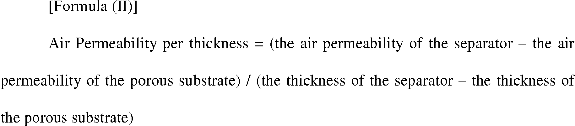
- In accordance with one aspect of the present invention, there is provided a separator, comprising a porous substrate; and a porous coating layer formed on at least one surface of the porous substrate and comprising a mixture of inorganic particles and a binder polymer, which has a value of a porosity x an air permeability per thickness in the range of 5 to 40, the porosity and the air permeability per thickness being defined by Formula (I) and Formula (II), respectively:

- Preferably, in the present invention, the porosity ranges from equal to or greater than 0.5 to less than 1, and the air permeability per thickness ranges from 5 to 80.
- The porous substrate may be made of a polyolefin-based polymer, but is not particularly limited thereto. The polyolefin-based polymer is preferably selected from polyethylene, polypropylene, polybutylene and polypentene.
- The inorganic particles used in the present invention may be inorganic particles having a dielectric constant of 5 or higher, inorganic particles having the ability to transport lithium ions, or a mixture thereof.
- Examples of the inorganic particles having a dielectric constant of 5 or higher include BaTiO3, Pb(Zrx,Ti1-x)O3 (PZT, 0<x<1), Pb1-xLaxZr1-yTiyO3 (PLZT, 0<x<1, 0<y<1), (1-x)Pb(Mg1/3Nb2/3)O3-xPbTiO3 (PMN-PT, 0<x<1), hafnia (HfO2), SrTiO3, SnO2, CeO2, MgO, NiO, CaO, ZnO, ZrO2, SiO2, Y2O3, Al2O3, SiC, TiO2 inorganic particles and a mixture thereof, but are not particularly limited thereto.
- Also, examples of the inorganic particles having the ability to transport lithium ions include lithium phosphate (Li3PO4), lithium titanium phosphate (LixTiy(PO4)3, 0<x<2, 0<y<3), lithium aluminum titanium phosphate (LixAlyTiz(PO4)3, 0<x<2, 0<y<1, 0<z<3), (LiAlTiP)xOy type glass (0<x<4, 0<y<13), lithium lanthanum titanate (LixLayTiO3,0<x<2, 0<y<3), lithium germanium thiophosphate (LixGeyPzSw, 0<x<4, 0<y<1, 0<z<1, 0<w<5), lithium nitride (LixNy, 0<x<4, 0<y<2), SiS2 type glass (LixSiySz, 0<x<3, 0<y<2, 0<z<4), P2S5 type glass (LixPySz, 0<x<3, 0<y<3, 0<z<7) inorganic particles, and a mixture thereof, but are not limited thereto.
- In addition, the binder polymer may be selected from the group consisting of polyvinylidene fluoride-co-hexafluoropropylene, polyvinylidene fluoride-cotrichloroethylene, polymethyl methacrylate, polybutyl acrylate, polyacrylonitrile, polyvinylpyrrolidone, polyvinyl acetate, polyvinyl alcohol, polyethylene-co-vinyl acetate, polyethylene oxide, polyarylate, cellulose acetate, cellulose acetate butyrate, cellulose acetate propionate, cyanoethylpullulan, cyanoethyl polyvinyl alcohol, cyanoethyl cellulose, cyanoethyl sucrose, pullulan, carboxymethyl cellulose, a low molecular compound having a molecular weight of 10,000 g/mol or less, and a mixture thereof, but are not limited thereto.
- The separator of the present invention may be used in an electrochemical device such as a lithium secondary battery and a super capacitor device.
- The separator having a porous coating layer according to the present invention has a porosity of the porous coating layer, which is controlled depending on the air permeability of the porous substrate, and thus exhibit superior ionic conductivity as well as good mechanical properties, thereby contributing to improve the performance and safety of an electrochemical device.
-
-
FIG. 1 is a photograph of an equipment used for measuring an air permeability in the Examples and Comparative Examples illustrated herein. -
FIG. 2 is a photograph of an equipment used for measuring a thickness in the Examples and Comparative Examples illustrated herein. - Hereinafter, the present invention will be described in detail. Prior to the description, it should be understood that the terms used in the specification and the appended claims should not be construed as limited to general and dictionary meanings, but interpreted based on the meanings and concepts corresponding to technical aspects of the present invention on the basis of the principle that the inventor is allowed to define terms appropriately for the best explanation. Also, the embodiments proposed herein are just a preferable example for the purpose of illustrations only, not intended to limit the scope of the disclosure, so it should be understood that other equivalents and modifications could be made thereto without departing from the spirit and scope of the disclosure.
- The present invention provides a separator, comprising a porous substrate; and a porous coating layer formed on at least one surface of the porous substrate and comprising a mixture of inorganic particles and a binder polymer, which has a value of a porosity x an air permeability per thickness in the range of 5 to 40, the porosity and the air permeability per thickness being defined by Formula (I) and Formula (II), respectively:


- The terms 'the weight ratio of the inorganic particles' and 'the weight ratio of the binder polymer', which are used herein, refer to the weight of each of the inorganic particles and the binder polymer based on 100 parts by weight of the total weight of the inorganic particles and the binder polymer.
- Also, it is understood that the terms 'a porosity' and 'an air permeability per thickness', which are used herein, refer to the porosity and air permeability of the porous coating layer, unless other indication is given.
- In the porous coating layer, the binder polymer allows the adhesion of the inorganic particles so that the inorganic particles can be bound with each other (i.e., the binder polymer connects and immobilizes the inorganic particles therebetween), and also, the inorganic particles are substantially present in contact with each other to form a closest packed structure, and an interstitial volume generated from the contact of the inorganic particles with each other becomes a pore of the porous coating layer. The separator comprising such a porous coating layer can maintain air permeability with improved thermal safety, due to the nature of the porous coating layer.
- However, the binder polymer functions to hinder ions from transferring to increase the resistance of the ions. Accordingly, the use of the binder polymer in an excessive amount may deteriorate the performance of an electrochemical device, while the use of the binder polymer in a small amount may cause the release of the inorganic particles to deteriorate mechanical properties. Therefore, it is important to control the amount of the binder.
- Also, as the porous coating layer is present, the air permeability of the porous substrate is actually reduced. Accordingly, it is necessary to define the air permeability range of the porous coating layer in a certain degree so that the performance of an electrochemical device is not excessively deteriorated. That is, it is preferred to control the properties of the porous coating layer taking into account the air permeability of the porous substrate to be used.
- Since in the separator of the present invention, a value of a porosity x an air permeability per thickness is in the range of 5 to 40, the porosity thereof can be controlled depending on the air permeability of the porous substrate, to allow the coating layer to have good mechanical properties and ionic conductivity, and eventually contribute to improve the performance and safety of an electrochemical device.
- More preferably, in the separator of the present invention, a porosity ranges from equal to or greater than 0.5 to less than 1, and an air permeability per thickness ranges from 5 to 80, while satisfying a value of a porosity x an air permeability per thickness in the range of 5 to 40.
- The term "porosity" which is used herein refers to the ratio of pore spaces occupied in a porous substance, i.e., a fraction of the volume of empty pores over the total volume in the substance. In the present invention, the porosity is represented by a value obtained by dividing the weight ratio of the inorganic particles and the binder polymer by each density.
- In the present invention, the term "air permeability per thickness" refers to a value obtained by dividing the difference between the air permeability of the separator and the air permeability of the porous substrate by the thickness of the porous layer (the thickness of the separator - the thickness of the porous substrate). The unit for the porosity is 'sec/100 ml', and the unit for the thickness of the porous coating layer is 'µm'.
- If the value of 'a porosity x an air permeability per thickness' is less than 5, a space between the inorganic particles becomes overly broad, from which an inner short circuit on the infiltration of a foreign substance may occur to deteriorate safety. If the value of 'a porosity x an air permeability per thickness' is greater than 40, passages capable of transporting lithium ions may be reduced to severely deteriorate ionic conductivity, and thus, the separator fails to be used in an electrochemical device.
- In the present invention, the porous substrate may be made of a polyolefin-based polymer. The polyolefin-based polymer is preferably selected from polyethylene, polypropylene, polybutylene and polypentene.
- The inorganic particles used in the present invention may be inorganic particles having a dielectric constant of 5 or higher, inorganic particles having the ability to transport lithium ions, or a mixture thereof.
- Non-limiting examples of the inorganic particles having a dielectric constant of 5 or higher include BaTiO3, Pb(Zrx,Ti1-x)O3 (PZT, 0<x<1), Pb1-xLaxZr1-yTiyO3 (PLZT, 0<x<1, 0<y<1), (1-x)Pb(Mg1/3Nb2/3)O3-xPbTiO3 (PMN-PT, 0<x<1), hafnia (HfO2), SrTiO3, SnO2, CeO2, MgO, NiO, CaO, ZnO, ZrO2, SiO2, Y2O3, Al2O3, TiO2, SiC, inorganic particles and a mixture thereof. Also, non-limiting examples of the inorganic particles having the ability to transport lithium ions include lithium phosphate (Li3PO4), lithium titanium phosphate (LixTiy(PO4)3, 0<x<2, 0<y<3), lithium aluminum titanium phosphate (LixAlyTiz(PO4)3, 0<x<2, 0<y<1, 0<z<3), (LiAlTiP)xOy type glass (0<x<4, 0<y<13), lithium lanthanum titanate (LixLayTiO3,0<x<2, 0<y<3), lithium germanium thiophosphate (LixGeyPzSw, 0<x<4, 0<y<1, 0<z<1, 0<w<5), lithium nitride (LixNy, 0<x<4, 0<y<2), SiS2 type glass (LixSiySz, 0<x<3, 0<y<2, 0<z<4), P2S5 type glass (LixPySz, 0<x<3, 0<y<3, 0<z<7), and a mixture thereof.
- The binder polymer may be any one selected from the group consisting of polyvinylidene fluoride-co-hexafluoropropylene, polyvinylidene fluoride-cotrichloroethylene, polymethyl methacrylate, polybutyl acrylate, polyacrylonitrile, polyvinylpyrrolidone, polyvinyl acetate, polyvinyl alcohol, polyethylene-co-vinyl acetate, polyethylene oxide, polyarylate, cellulose acetate, cellulose acetate butyrate, cellulose acetate propionate, cyanoethylpullulan, cyanoethyl polyvinyl alcohol, cyanoethyl cellulose, cyanoethyl sucrose, pullulan, carboxymethyl cellulose, a low molecular compound having a molecular weight of 10,000 g/mol or less, and a mixture thereof.
- Further, the present invention provides an electrochemical device comprising a cathode, an anode, the above-mentioned separator which is interposed between the cathode and the anode, and an electrolyte solution.
- In the present invention, the cathode and the anode are not particularly limited, and may be manufactured by binding an electrode active material to an electrode current collector according to a conventional method known in the art.
- As a cathode active material, those that are commonly used in cathodes of conventional electrochemical devices may be used. Non-limiting examples of the cathode active material may be any one selected from the group consisting of LiCoO2, LiNiO2, LiMn2O4, LiCoPO4, LiFePO4, LiNiMnCoO2, LiNi1-x-y-zCoxM1yM2zO2 (wherein M1 and M2 are each independently selected from the group consisting of Al, Ni, Co, Fe, Mn, V, Cr, Ti, W, Ta, Mg and Mo, and x, y and z are each independently an atomic fraction of oxide-forming elements, in which 0 ≤ x < 0.5, 0 ≤ y < 0.5, 0 ≤ z < 0.5, and x+y+z < 1).
- Also, as an anode active material, those that are commonly used in anodes of conventional electrochemical devices may be used, and non-limiting examples thereof include lithium, lithium alloys, and lithium intercalation materials such as carbon, petroleum coke, activated carbon, graphite and other carbonaceous materials. Non-limiting examples of a usable cathode current collector include aluminum foils, nickel foils and a combination thereof. Non-limiting examples of a usable anode current collector include copper foils, gold foils, nickel foils, copper alloy foils and a combination thereof.
- The electrolyte solution which may be used in the present invention is obtained by dissolving or dissociating a salt in an organic solvent. The salt has a structure represented by A+B- wherein A+ is an alkali metal cation such as Li+, Na+, K+ and a combination thereof and B- is an anion such as PF6 -, BF4 -, Cl-, Br-, I-, ClO4 -, AsF6 -, CH3CO2 -, CF3SO3 -, N(CF3SO2)2 -, C(CF2SO2)3 - and a combination thereof. Examples of the organic solvent include propylene carbonate (PC), ethylene carbonate (EC), diethyl carbonate (DEC), dimethyl carbonate (DMC), dipropyl carbonate (DPC), dimethyl sulfoxide, acetonitrile, dimethoxyethane, diethoxyethane, tetrahydrofuran, N-methyl-2-pyrrolidone (NMP), ethyl methyl carbonate (EMC), γ-butyrolactone and a mixture thereof, but are not limited thereto. The electrolyte solution may be introduced in any suitable step during the manufacturing of the electrochemical device depending on the manufacturing processes and desired physical properties of a final product. Specifically, the electrolyte may be introduced before assembling a battery or in the final step of the assembling.
- Hereinafter, various preferred examples of the present invention will be described in detail for better understanding. However, the examples of the present invention may be modified in various ways, and they should not be interpreted as limiting the scope of the invention. The examples of the present invention are just for better understanding of the invention to persons having ordinary skill in the art.
- 5 parts by weight of PVdF-HFP copolymer and 5 parts by weight of cyanoethyl polyvinyl alcohol were dissolved in acetone. To the resultant binder solution, 90 parts by weight of alumina (Density: 4.0 g/cm3) was added, and dispersed by way of a ball mill method, to obtain a slurry.
- The slurry obtained above was coated on one surface of a 9 µm-thick polyolefin film (Asahi Kasei, ND509) and dried, to form a porous coating layer having an average thickness of 5 µm.
- 5 parts by weight of cyanoethyl polyvinyl alcohol was dissolved in acetone. To the resultant binder solution, 95 parts by weight of alumina was added, and dispersed by way of a ball mill method, to obtain a slurry.
- The slurry obtained above was coated on one surface of a 9 µm-thick polyolefin film (Asahi Kasei, ND509) and dried, to form a porous coating layer having an average thickness of 5 µm.
- 5 parts by weight of PVdF-HFP copolymer and 5 parts by weight of cyanoethyl polyvinyl alcohol were dissolved in acetone. To the resultant binder solution, 90 parts by weight of BaTiO3 (Density: 5.7 g/cm3) was added, and dispersed by way of a ball mill method, to obtain a slurry.
- The slurry obtained above was coated on one surface of a 9 µm-thick polyolefin film (Asahi Kasei, ND509) and dried, to form a porous coating layer having an average thickness of 5 µm.
- 10 parts by weight of PVdF-HFP copolymer and 5 parts by weight of cyanoethyl polyvinyl alcohol were dissolved in acetone. To the resultant binder solution, 85 parts by weight of alumina was added, and dispersed by way of a ball mill method, to obtain a slurry.
- The slurry obtained above was coated on one surface of a 9 µm-thick polyolefin film (Asahi Kasei, ND509) and dried, to form a porous coating layer having an average thickness of 5 µm.
- 2 parts by weight of PVdF-HFP copolymer and 3 parts by weight of cyanoethyl polyvinyl alcohol were dissolved in acetone. To the resultant binder solution, 95 parts by weight of alumina was added, and dispersed by way of a ball mill method, to obtain a slurry.
- The slurry obtained above was coated on one surface of a 9 µm-thick polyolefin film (Asahi Kasei, ND509) and dried, to form a porous coating layer having an average thickness of 5 µm.
- 10 parts by weight of PVdF-HFP copolymer and 10 parts by weight of cyanoethyl polyvinyl alcohol were dissolved in acetone. To the resultant binder solution, 80 parts by weight of alumina was added, and dispersed by way of a ball mill method, to obtain a slurry.
- The slurry obtained above was coated on one surface of a 9 µm-thick polyolefin film (Asahi Kasei, ND509) and dried, to form a porous coating layer having an average thickness of 5 µm.
- 20 parts by weight of PVdF-HFP copolymer was dissolved in acetone. To the resultant binder solution, 80 parts by weight of alumina was added, and dispersed by way of a ball mill method, to obtain a slurry.
- The slurry obtained above was coated on one surface of a 9 µm-thick polyolefin film (Asahi Kasei, ND509) and dried, to form a porous coating layer having an average thickness of 5 µm.
- 25 parts by weight of PVdF-HFP copolymer and 25 parts by weight of cyanoethyl polyvinyl alcohol were dissolved in acetone. To the resultant binder solution, 50 parts by weight of alumina was added, and dispersed by way of a ball mill method, to obtain a slurry.
- The slurry obtained above was coated on one surface of a 9 µm-thick polyolefin film (Asahi Kasei, ND509) and dried, to form a porous coating layer having an average thickness of 5 µm.
- The separators prepared in Examples 1 to 5 and Comparative Examples 1 to 3 were measured for their properties, and the results thereof are shown in Table 1. Among the properties of the separators, the porosity thereof was obtained by measuring the time it takes for 100 ml of air to pass through each separator using Gurley Type Densometer (Toyoseki) as shown in
FIG. 1 , and the thickness thereof was obtained by cutting each porous substrate and each separator into a piece having a size of 5cm x 5cm and measuring 5 times the thickness of four corners and the dead center for each piece using a thickness gauge (Tesa, Swiss) as shown inFIG. 2 , followed by calculating the average.Table 1 Ex. 1 Ex. 2 Ex. 3 Ex. 4 Ex. 5 Com. Ex. 1 Com. Ex. 2 Com. Ex. 3 Porosity 0.701 0.708 0.768 0.685 0.724 0.652 0.713 0.505 Air Permeability of Porous Substrate 150 150 150 150 150 150 150 150 Air Permeability of Separator 350 280 330 410 220 500 180 800 Thickness of Porous Substrate 9 9 9 9 9 9 9 9 Thickness of Separator 14 14 14 14 14 14 14 14 Air Permeability per thickness 40 26 36 52 20 70 6 130 Porosity×Air Permeability per thickness 28.04 18.41 27.65 35.62 10.14 45.64 4.12 65.65 Ionic Conductivity (×E4 S/cm) 5.6 4.6 5.2 3.7 6.4 1.4 Unmeasurable 0.2 - As shown in Table 1, the separators of Examples 1 to 5 exhibited an ionic conductivity of 3.7 to 6.4 (xE4 S/cm), whereas those of Comparative Examples 1 and 3, 1.4 and 0.2 (xE4 S/cm), respectively. That is, the separators of Examples 1 to 5 were confirmed to have a superior ionic conductivity as compared with those of Comparative Examples 1 and 3. Also, it was confirmed that the separator of Comparative Example 2 cannot be used as a separator as the porous coating layer thereof was melted in an electrolyte solution.
Claims (10)
- A separator, comprising a porous substrate; and a porous coating layer formed on at least one surface of the porous substrate and comprising a mixture of inorganic particles and a binder polymer, which has a value of a porosity x an air permeability per thickness in the range of 5 to 40, the porosity and the air permeability per thickness being defined by Formula (I) and Formula (II), respectively:


- The separator according to claim 1, wherein the porosity ranges from equal to or greater than 0.5 to less than 1, and the air permeability per thickness ranges from 5 to 80.
- The separator according to claim 1, wherein the porous substrate is made of a polyolefin-based polymer.
- The separator according to claim 3, wherein the porous substrate is made of a polyolefin-based polymer selected from the group consisting of polyethylene, polypropylene, polybutylene and polypentene.
- The separator according to claim 1, wherein the inorganic particles are selected from the group consisting of inorganic particles having a dielectric constant of 5 or higher, inorganic particles having the ability to transport lithium ions, and a mixture thereof.
- The separator according to claim 5, wherein the inorganic particles having a dielectric constant of 5 or higher are selected from the group consisting of BaTiO3, Pb(Zrx,Ti1-x)O3 (PZT, 0<x<1), Pb1-xLaxZr1-yTiyO3 (PLZT, 0<x<1, 0<y<1), (1-x)Pb(Mg1/3Nb2/3)O3-xPbTiO3 (PMN-PT, 0<x<1), hafnia (HfO2), SrTiO3, SnO2, CeO2, MgO, NiO, CaO, ZnO, ZrO2, SiO2, Y2O3, Al2O3, SiC, TiO2 inorganic particles and a mixture thereof.
- The separator according to claim 5, wherein the inorganic particles having the ability to transport lithium ions are selected from the group consisting of lithium phosphate (Li3PO4), lithium titanium phosphate (LixTiy(PO4)3, 0<x<2, 0<y<3), lithium aluminum titanium phosphate (LixAlyTiz(PO4)3, 0<x<2, 0<y<1, 0<z<3), (LiAlTiP)xOy type glass (0<x<4, 0<y<13), lithium lanthanum titanate (LixLayTiO3,0<x<2, 0<y<3), lithium germanium thiophosphate (LixGeyPzSw, 0<x<4, 0<y<1, 0<z<1, 0<w<5), lithium nitride (LixNy, 0<x<4, 0<y<2), SiS2 type glass (LixSiySz, 0<x<3, 0<y<2, 0<z<4), P2S5 type glass (LixPySz, 0<x<3, 0<y<3, 0<z<7) particles, and a mixture thereof.
- The separator according to claim 1, wherein the binder polymer is selected from the group consisting of polyvinylidene fluoride-co-hexafluoropropylene, polyvinylidene fluoride-co-trichloroethylene, polymethyl methacrylate, polybutyl acrylate, polyacrylonitrile, polyvinylpyrrolidone, polyvinyl acetate, polyvinyl alcohol, polyethylene-co-vinyl acetate, polyethylene oxide, polyarylate, cellulose acetate, cellulose acetate butyrate, cellulose acetate propionate, cyanoethylpullulan, cyanoethyl polyvinyl alcohol, cyanoethyl cellulose, cyanoethyl sucrose, pullulan, carboxymethyl cellulose, a low molecular compound having a molecular weight of 10,000 g/mol or less, and a mixture thereof.
- An electrochemical device, comprising a cathode, an anode and a separator interposed between the cathode and the anode,
wherein the separator is defined in any one of claims 1 to 8. - The electrochemical device according to claim 9, which is a lithium secondary battery.
Applications Claiming Priority (2)
| Application Number | Priority Date | Filing Date | Title |
|---|---|---|---|
| KR20110112980 | 2011-11-01 | ||
| PCT/KR2012/009075 WO2013066052A1 (en) | 2011-11-01 | 2012-10-31 | Separator and electrochemical device having same |
Publications (2)
| Publication Number | Publication Date |
|---|---|
| EP2775553A1 true EP2775553A1 (en) | 2014-09-10 |
| EP2775553A4 EP2775553A4 (en) | 2015-10-21 |
Family
ID=48659355
Family Applications (1)
| Application Number | Title | Priority Date | Filing Date |
|---|---|---|---|
| EP12844795.0A Ceased EP2775553A4 (en) | 2011-11-01 | 2012-10-31 | Separator and electrochemical device having same |
Country Status (6)
| Country | Link |
|---|---|
| US (1) | US9786890B2 (en) |
| EP (1) | EP2775553A4 (en) |
| JP (1) | JP5795646B2 (en) |
| KR (1) | KR101312431B1 (en) |
| CN (1) | CN103329306B (en) |
| WO (1) | WO2013066052A1 (en) |
Families Citing this family (15)
| Publication number | Priority date | Publication date | Assignee | Title |
|---|---|---|---|---|
| US11050095B2 (en) | 2004-12-08 | 2021-06-29 | Maxell Holdings, Ltd. | Separator for electrochemical device, and electrochemical device |
| KR101676446B1 (en) * | 2013-09-30 | 2016-11-15 | 주식회사 엘지화학 | Method for manufacturing a separator for lithium secondary battery, the separator manufactured by the method and lithium secondary battery including the same |
| US10256471B2 (en) * | 2014-12-22 | 2019-04-09 | Samsung Sdi Co., Ltd. | Electrode winding element for non-aqueous electrolyte rechareable battery, non-aqueous electrolyte rechargeable lithium battery including same, method of preparing same |
| US9508976B2 (en) | 2015-01-09 | 2016-11-29 | Applied Materials, Inc. | Battery separator with dielectric coating |
| WO2017010779A1 (en) * | 2015-07-10 | 2017-01-19 | 주식회사 엘지화학 | Separator and electrochemical device comprising same |
| US10797314B2 (en) * | 2016-07-29 | 2020-10-06 | Blue Current, Inc. | Compliant solid-state ionically conductive composite materials and method for making same |
| CN107436670A (en) * | 2017-08-04 | 2017-12-05 | 合肥支招信息科技有限公司 | A kind of extendible notebook rechargeable battery |
| JP7414709B2 (en) | 2017-08-17 | 2024-01-16 | アプライド マテリアルズ インコーポレイテッド | LI ion battery without olefin separator |
| KR102277377B1 (en) | 2018-05-11 | 2021-07-14 | 주식회사 엘지에너지솔루션 | Anti-flame Separator for Secondary Battery |
| KR102543254B1 (en) * | 2018-06-26 | 2023-06-13 | 셴젠 시니어 테크놀로지 매테리얼 씨오., 엘티디. | Composite lithium battery separator and its manufacturing method |
| US11588209B2 (en) | 2018-08-21 | 2023-02-21 | Applied Materials, Inc. | Ultra-thin ceramic coating on separator for batteries |
| CN110635133B (en) * | 2019-08-30 | 2021-08-06 | 东莞赣锋电子有限公司 | A kind of fast charging lithium ion battery and preparation method thereof |
| CN115244745A (en) * | 2020-03-25 | 2022-10-25 | 株式会社Lg新能源 | Apparatus and method for manufacturing unit cells |
| KR20230000710A (en) | 2021-06-25 | 2023-01-03 | 주식회사 엘지에너지솔루션 | Separator for Secondary Batttery |
| CN117438743A (en) * | 2022-07-14 | 2024-01-23 | 华为技术有限公司 | Battery separator and preparation method thereof, battery and electronic device |
Family Cites Families (11)
| Publication number | Priority date | Publication date | Assignee | Title |
|---|---|---|---|---|
| KR100573358B1 (en) * | 2002-09-17 | 2006-04-24 | 가부시키가이샤 도모에가와 세이시쇼 | Separators for lithium ion secondary batteries and lithium ion secondary batteries including the same |
| KR100659855B1 (en) * | 2005-04-25 | 2006-12-19 | 삼성에스디아이 주식회사 | Secondary Battery Separator |
| KR20090007710A (en) * | 2006-03-17 | 2009-01-20 | 산요덴키가부시키가이샤 | Nonaqueous Electrolyte Battery and Manufacturing Method Thereof |
| JP4931083B2 (en) * | 2007-01-30 | 2012-05-16 | 旭化成イーマテリアルズ株式会社 | Multilayer porous membrane and method for producing the same |
| KR100727248B1 (en) * | 2007-02-05 | 2007-06-11 | 주식회사 엘지화학 | Organic / inorganic composite membrane coated with porous active layer and electrochemical device |
| EP2517880B1 (en) * | 2007-06-06 | 2014-03-26 | Asahi Kasei E-materials Corporation | Multilayer porous film |
| JP5062526B2 (en) * | 2007-09-27 | 2012-10-31 | 三洋電機株式会社 | Nonaqueous electrolyte battery separator and nonaqueous electrolyte battery |
| JP5937776B2 (en) * | 2008-05-22 | 2016-06-22 | 日立マクセル株式会社 | Battery separator and battery |
| US9142819B2 (en) | 2008-09-03 | 2015-09-22 | Lg Chem, Ltd. | Separator having porous coating layer, and electrochemical device containing the same |
| KR101054976B1 (en) * | 2009-03-31 | 2011-08-05 | 주식회사 엘지화학 | Separator with a porous coating layer and an electrochemical device having the same |
| KR20110075631A (en) * | 2009-12-28 | 2011-07-06 | 롯데알미늄 주식회사 | Separator with nanopores and energy storage device using the same |
-
2012
- 2012-10-31 KR KR1020120122137A patent/KR101312431B1/en active Active
- 2012-10-31 EP EP12844795.0A patent/EP2775553A4/en not_active Ceased
- 2012-10-31 JP JP2013541938A patent/JP5795646B2/en active Active
- 2012-10-31 CN CN201280004404.7A patent/CN103329306B/en active Active
- 2012-10-31 WO PCT/KR2012/009075 patent/WO2013066052A1/en not_active Ceased
-
2013
- 2013-05-28 US US13/903,195 patent/US9786890B2/en active Active
Also Published As
| Publication number | Publication date |
|---|---|
| JP5795646B2 (en) | 2015-10-14 |
| US20130260208A1 (en) | 2013-10-03 |
| CN103329306A (en) | 2013-09-25 |
| US9786890B2 (en) | 2017-10-10 |
| EP2775553A4 (en) | 2015-10-21 |
| JP2013544430A (en) | 2013-12-12 |
| WO2013066052A1 (en) | 2013-05-10 |
| KR20130048177A (en) | 2013-05-09 |
| CN103329306B (en) | 2017-10-24 |
| KR101312431B1 (en) | 2013-09-27 |
Similar Documents
| Publication | Publication Date | Title |
|---|---|---|
| US9786890B2 (en) | Separator and electrochemical device having the same | |
| EP2626942B1 (en) | Electrochemical device with improved cycle characteristics | |
| EP2838140B1 (en) | Electrode having porous coating layer, manufacturing method thereof and electrochemical device | |
| EP2779275B1 (en) | Separator, and electrochemical device comprising same | |
| EP2800166B1 (en) | Method for manufacturing a separator | |
| EP2840628B1 (en) | Method for manufacturing separator, separator formed thereby, and electrochemical device comprising said separator | |
| EP3410515B1 (en) | Organic/inorganic composite separator having porous active coating layer and electrochemical device containing the same | |
| EP2860789B1 (en) | Separator and an electro-chemical device having the same | |
| EP3190652B1 (en) | Electrode assembly having improved safety, manufacturing method therefor and electrochemical element comprising electrode assembly | |
| US9741986B2 (en) | Electrode for electrochemical device and electrochemical device comprising the same | |
| US20130004817A1 (en) | Electrode assembly and method for constructing the same | |
| EP3648197A1 (en) | Asymmetrically structured flame-retardant separator for secondary battery | |
| KR20190067124A (en) | A Separator for a lithiumion secondary battery and a lithium ion secondary battery comprising the same | |
| KR102830174B1 (en) | A separator for an electrochemical device and an electrochemical device comprising the same | |
| EP3048660A1 (en) | Secondary battery having improved life span performance | |
| KR101596491B1 (en) | A electrochemical device for progressing cycle characteristic | |
| JP5902692B6 (en) | Electrochemical device with improved cycle characteristics | |
| KR20260054219A (en) | A sperator for an electrochemical device and an electrochemical device comprising the same |
Legal Events
| Date | Code | Title | Description |
|---|---|---|---|
| PUAI | Public reference made under article 153(3) epc to a published international application that has entered the european phase |
Free format text: ORIGINAL CODE: 0009012 |
|
| 17P | Request for examination filed |
Effective date: 20130522 |
|
| AK | Designated contracting states |
Kind code of ref document: A1 Designated state(s): AL AT BE BG CH CY CZ DE DK EE ES FI FR GB GR HR HU IE IS IT LI LT LU LV MC MK MT NL NO PL PT RO RS SE SI SK SM TR |
|
| DAX | Request for extension of the european patent (deleted) | ||
| RA4 | Supplementary search report drawn up and despatched (corrected) |
Effective date: 20150922 |
|
| RIC1 | Information provided on ipc code assigned before grant |
Ipc: H01M 2/14 20060101AFI20150916BHEP Ipc: H01M 10/058 20100101ALI20150916BHEP Ipc: H01M 2/16 20060101ALI20150916BHEP |
|
| RAP1 | Party data changed (applicant data changed or rights of an application transferred) |
Owner name: TORAY BATTERY SEPARATOR FILM CO., LTD. Owner name: LG CHEM, LTD. |
|
| 17Q | First examination report despatched |
Effective date: 20160826 |
|
| REG | Reference to a national code |
Ref country code: DE Ref legal event code: R003 |
|
| RAP1 | Party data changed (applicant data changed or rights of an application transferred) |
Owner name: TORAY INDUSTRIES, INC. Owner name: LG CHEM, LTD. |
|
| 18R | Application refused |
Effective date: 20171106 |