EP2775497A1 - Switch - Google Patents
Switch Download PDFInfo
- Publication number
- EP2775497A1 EP2775497A1 EP14154126.8A EP14154126A EP2775497A1 EP 2775497 A1 EP2775497 A1 EP 2775497A1 EP 14154126 A EP14154126 A EP 14154126A EP 2775497 A1 EP2775497 A1 EP 2775497A1
- Authority
- EP
- European Patent Office
- Prior art keywords
- contact
- movable contact
- disposed
- movable
- plate
- Prior art date
- Legal status (The legal status is an assumption and is not a legal conclusion. Google has not performed a legal analysis and makes no representation as to the accuracy of the status listed.)
- Granted
Links
Images




Classifications
-
- H—ELECTRICITY
- H01—ELECTRIC ELEMENTS
- H01H—ELECTRIC SWITCHES; RELAYS; SELECTORS; EMERGENCY PROTECTIVE DEVICES
- H01H13/00—Switches having rectilinearly-movable operating part or parts adapted for pushing or pulling in one direction only, e.g. push-button switch
- H01H13/02—Details
- H01H13/12—Movable parts; Contacts mounted thereon
- H01H13/20—Driving mechanisms
-
- H—ELECTRICITY
- H01—ELECTRIC ELEMENTS
- H01H—ELECTRIC SWITCHES; RELAYS; SELECTORS; EMERGENCY PROTECTIVE DEVICES
- H01H3/00—Mechanisms for operating contacts
- H01H3/32—Driving mechanisms, i.e. for transmitting driving force to the contacts
- H01H3/42—Driving mechanisms, i.e. for transmitting driving force to the contacts using cam or eccentric
-
- H—ELECTRICITY
- H01—ELECTRIC ELEMENTS
- H01H—ELECTRIC SWITCHES; RELAYS; SELECTORS; EMERGENCY PROTECTIVE DEVICES
- H01H13/00—Switches having rectilinearly-movable operating part or parts adapted for pushing or pulling in one direction only, e.g. push-button switch
- H01H13/02—Details
- H01H13/023—Light-emitting indicators
-
- H—ELECTRICITY
- H01—ELECTRIC ELEMENTS
- H01H—ELECTRIC SWITCHES; RELAYS; SELECTORS; EMERGENCY PROTECTIVE DEVICES
- H01H13/00—Switches having rectilinearly-movable operating part or parts adapted for pushing or pulling in one direction only, e.g. push-button switch
- H01H13/02—Details
- H01H13/12—Movable parts; Contacts mounted thereon
-
- H—ELECTRICITY
- H01—ELECTRIC ELEMENTS
- H01H—ELECTRIC SWITCHES; RELAYS; SELECTORS; EMERGENCY PROTECTIVE DEVICES
- H01H1/00—Contacts
- H01H2001/0005—Redundant contact pairs in one switch for safety reasons
Definitions
- the present invention relates to a switch, particularly to a push-button switch.
- FIG. 8-504050 discloses a flat key switch as a switch in which a contact can be opened and closed by a pressing operation.
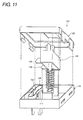
- Fig. 11 is an exploded perspective view illustrating a configuration of the flat key switch disclosed in International Patent Publication No. 8-504050.
- a key switch 100 of International Patent Publication No. 8-504050 is accommodated in a housing including a lower portion 110 and a lid portion 120 covering the lower portion 110.
- the key switch 100 is opened and closed by switching between contact and non-contact of a fixed contact piece 144 and a contact shoe 146.
- the contact shoe 146 is constructed by a cyclic thin-plate 150. When a push-rod 130 is pushed in, the cyclic thin-plate 150 is bent in a direction perpendicular to a direction, in which the push-rod 130 is pushed in, by an opening and closing cam 140 provided in the push-rod 130.
- the contact shoe 146 constructed by the cyclic thin-plate 150 moves relative to the fixed contact piece 144 to come into contact with or separate (becomes the non-contact) from the fixed contact piece 144.
- the key switch 100 of International Patent Publication No. 8-504050 is opened and closed by switching between the contact and the non-contact of the fixed contact piece 144 and the contact shoe 146 in the direction perpendicular to the direction in which the push-rod 130 is pushed in. Therefore, the key switch 100 is suitable for the switch in which an appearance has a flat structure.
- the contact shoe 146 constructed by the cyclic thin-plate 150 is disposed on a side of one of side surfaces constituting a quadratic prism of the lower portion 110.
- the cyclic thin-plate 150 has a cyclic structure because the cyclic thin-plate 150 is bent in the direction perpendicular to the direction in which the push-rod 130 is pushed in. Because a certain degree of flexibility is provided to the cyclic structure, the dimensions of the cyclic thin-plate 150 are enlarged in the direction perpendicular to the direction in which the push-rod 130 is pushed in.
- a space of the contact shoe 146 constructed by the cyclic thin-plate 150 is enlarged in the key switch of International Patent Publication No. 8-504050 . Therefore, it is difficult that the member is disposed in the center of the key switch without changing the dimensions of the appearance.
- a lighted push-button switch desirably an LED that is of a light source is disposed in a central position with respect to a button operating surface such that the button operating surface is homogeneously illuminated with light.
- the key switch of International Patent Publication No. 8-504050 is applied to the lighted push-button switch, it is difficult that the LED is disposed in the center of the operating surface of the key switch without changing the dimensions of the appearance. It is necessary to enlarge the dimensions of the appearance of the key switch in order to dispose the LED in the center of the operating surface of the key switch.
- the present invention has been devised to solve the problems described above, and an object thereof is to provide a switch in which the space where the member is disposed can be ensured in the center without changing the dimensions of the appearance.
- a switch includes: a contact mechanism that includes an opening and closing unit, the opening and closing unit including a movable contact and a fixed contact; a casing that is formed into a polygonal-column box shape, a central space of the casing being defined by an internal wall; and a pressing member that is attached while being vertically movable in an axial direction of the polygonal column in a space of the casing, the pressing member including a cam shape in which a dimension in a horizontal direction perpendicular to the axial direction varies in the axial direction.
- the contact mechanism includes a plate-like member including a support supported by the casing, the plate-like member includes a movable contact portion in which the movable contact is provided, the movable contact portion abutting on the cam shape and being elastically deformed in the horizontal direction in conjunction with the vertical movement, the movable contact moves horizontally to come into contact with or separate from the fixed contact by an elastic deformation of the movable contact portion, the movable contact portion is disposed while bent in an outer peripheral space between the internal wall and sidewalls constituting the polygonal column, and the sidewall closest to a position where the support is disposed differs from the sidewall closest to a position where a portion coming into contact with the cam shape is disposed.
- the contact mechanism includes the plate-like member that includes the support supported by the casing.
- the plate-like member includes the movable contact portion in which the movable contact is provided.
- the movable contact portion abuts on the cam shape in which the dimension in the horizontal direction perpendicular to the axial direction varies in the axial direction.
- the movable contact portion is elastically deformed in the horizontal direction in conjunction with the vertical movement. In the contact mechanism, by the elastic deformation of the movable contact portion, the movable contact moves horizontally to come into contact with or separate from the fixed contact.
- the force in the direction of the vertical movement by the pressing member is converted into the force in the horizontal direction perpendicular to the direction of the vertical movement, and the fixed contact and the movable contact are brought into contact with or separated from each other, thereby implementing the opening and closing of the electrical contact. Therefore, the dimension of the switch can be reduced in the direction of the vertical movement.
- the movable contact portion is disposed while bent in the outer peripheral space between the internal wall and the sidewalls constituting the polygonal column, the sidewall closest to the position where the support is disposed differs from the sidewall closest to the position where the portion coming into contact with the cam shape is disposed. Therefore, a distance between the support that is of a support point and "the portion coming into contact with the cam shape" that is of a power point is lengthened, so that the force necessary to generate the elastic deformation of the movable contact portion can be reduced.
- the movable contact portion is configured to be bent along the sidewall, so that the outer peripheral space between the internal wall and the sidewalls constituting the polygonal column can be reduced.
- a volume of the central space can be enlarged without changing the dimensions of the casing. Therefore, according to the configuration, the space where the member is disposed can be ensured in the center of the casing without changing the dimensions of the appearance of the switch.
- a corner portion closest to the position where the support is disposed differs from a corner portion closest to the position where the portion coming into contact with the cam shape is disposed. Therefore, the distance between the support that is of the support point and "the portion coming into contact with the cam shape" that is of the power point can further be lengthened.
- any "cam shape” may be used as long as the dimension in the horizontal direction perpendicular to the axial direction varies in the axial direction and as long as the elastic deformation is horizontally generated in the movable contact portion.
- a shape having a concave-convex surface horizontally formed in a concave-convex manner and a shape having an inclination surface inclined with respect to the axial direction can be cited as an example of the "cam shape”.
- the contact mechanism includes the two plate-like members and the two opening and closing units corresponding to the two plate-like members, respectively.
- the contact mechanism includes the two plate-like members and the two opening and closing units corresponding to the two plate-like members, respectively, so that contact reliability can be improved between the movable contact and fixed contact of the switch.
- the two opening and closing units are disposed so as to become axisymmetrical with respect to a central axis of a direction of the vertical movement.
- the two opening and closing units are disposed so as to become axisymmetrical with respect to the central axis of the direction of the vertical movement, during a pressing operation of the switch, the force is not applied to the pressing member while biased toward one direction, but the force is evenly applied to the pressing member in the direction perpendicular to the vertical movement. Therefore, abrasion can be prevented in a specific portion of the pressing member to lengthen a lifetime of the switch.
- a fixed support configured to fix the fixed contact is formed in each plate-like member, in the two plate-like members, the fixed contact provided in the fixed support of a first plate-like member and the movable contact provided in the movable contact portion of a second plate-like member constitute a first opening and closing unit, and the fixed contact provided in the fixed support of the second plate-like member and the movable contact provided in the movable contact portion of the first plate-like member constitute a second opening and closing unit.
- the movable contact and the fixed contact are provided in each plate-like member, and the first opening and closing unit and the second opening and closing unit are constructed by the contacts included in the plate-like members different from each other with respect to the movable contacts and the fixed contacts.
- the number of components can be decreased, because the movable contact and the fixed contact are collectively provided in the one movable plate without separately providing the member used to move the movable contact and the member used to fix the fixed contact.
- the space where the member is disposed can be ensured in the center of the casing.
- a light source configured to emit light upward in the direction of the vertical movement is provided in the central space of the casing.
- the light source that emits the light upward in the direction of the vertical movement is provided in the central space of the casing ensured in the above manner. Therefore, the lighted push-button switch in which the button operating surface is homogeneously illuminated can be constructed without changing the dimensions of the appearance.
- the light source may include an LED mounted on a board and a light guide rod optically coupled to the LED.
- the light source may include a shell type LED. Therefore, use efficiency of the light can be improved.
- a compact switch is provided in the central space of the casing, and the compact switch is configured to open and close an electric circuit after another electric circuit is turned on by electrical contact between the movable contact and the fixed contact.
- the compact switch is provided in the central space of the casing ensured in the above manner.
- the compact switch is configured to open and close the electric circuit after another electric circuit is turned on by the electrical contact between the movable contact and the fixed contact, so that the switch of the present invention can be used as a two-stage switch.
- an abutment portion abutting on the cam shape and the support are disposed in a corner space of the casing.
- the abutment portion abutting on the cam shape and the support are disposed in the corner space of the casing, and the corner space of the casing is effectively used. Therefore, the space where the member is disposed can further be ensured in the center of the casing.
- the switch includes: the casing that is formed into the polygonal-column box shape, the central space of the casing being defined by the internal wall; and the pressing member that is attached while being vertically movable in the axial direction of the polygonal column in the space of the casing, the pressing member including the cam shape in which the dimension in the horizontal direction perpendicular to the axial direction varies in the axial direction.
- the contact mechanism includes the plate-like member including the support supported by the casing, the plate-like member includes the movable contact portion in which the movable contact is provided, the movable contact portion abutting on the cam shape and being elastically deformed in the horizontal direction in conjunction with the vertical movement, the movable contact moves horizontally to come into contact with or separate from the fixed contact by the elastic deformation of the movable contact portion, the movable contact portion is disposed while bent in the outer peripheral space between the internal wall and sidewalls constituting the polygonal column, and the sidewall closest to the position where the support is disposed differs from the sidewall closest to the position where the portion coming into contact with the cam shape is disposed.
- the space where the member is disposed can be ensured in the center without changing the dimensions of the appearance.
- Fig. 1 is an exploded perspective view illustrating a configuration of a push-button switch 10 according to a first embodiment.
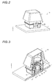
- Fig. 2 is a perspective view illustrating an appearance of the push-button switch 10.
- Fig. 3 is a sectional perspective view illustrating the configuration of the push-button switch 10. Figs. 2 and 3 illustrate a non-pressing state.
- the push-button switch 10 of the first embodiment is a contact type switch, and has the configuration particularly suitable for a lighted switch assembled in a keyboard, an industrial operation panel, an operation panel of a business-use video instrument, and a consumer product.
- the push-button switch 10 includes a keytop 1, an upper case 20 (casing), a plunger unit 30, a light source 40, a contact mechanism 50, a lower case 60 (casing), and a board 7.
- the upper case 20 is fitted in the lower case 60 to cover the contact mechanism 50 and support the plunger unit 30 such that the plunger unit 30 is vertically movable.
- the light source 40 includes an LED 41 and a light guide rod 42. As illustrated in Fig. 3 , the LED 41 is mounted on the board 7.
- the plunger unit 30 includes a plunger body (push-in member) 31 and a helical spring 32.
- a direction in which the push-button switch is pushed in is assumed to be a Z-direction.
- a side of the keytop 1 is assumed to be an upper side
- a side of the board 7 is assumed to be a lower side.
- a hole 21 in which an upper portion 31 A of the plunger body 31 can be inserted is made in the upper case 20.
- An engagement groove 33 to engage the keytop 1 is formed in the upper portion 31 A of the plunger body 31. Therefore, the upper portion 31 A of the plunger body 31 engages the keytop 1 while inserted in the hole 21 of the upper case 20.
- the lower case 60 has a quadratic-prism box shape, and is attached to the board 7 as illustrated in Fig. 1 .
- a communication pipe 61 internal wall
- the light source 40 is accommodated in the communication pipe 61.
- the LED 41 mounted on the board 7 is disposed immediately above the communication pipe 61.
- the light guide rod 42 is inserted in the communication pipe 61, and supported in a predetermined position by engagement between a latching portion 42a and a communication pipe 61. Light from the LED 41 is coupled to the light guide rod 42, is guided in the light guide rod 42, and exits upward.
- An insertion pipe 62 (internal wall) is formed in the lower case 60 so as to surround the communication pipe 61.
- the insertion pipe 62 is configured to neither pierce a bottom surface of the lower case 60 nor be communicated to the board 7.
- the helical spring 32 of the plunger unit 3 is accommodated in a space between an outer wall of the communication pipe 61 and an inner wall of the insertion pipe 62. That is, in the lower case 60, a central space is defined by the communication pipe 61 and the insertion pipe 62.
- the contact mechanism 50 is accommodated in a space (outer peripheral space) surrounded by an outer wall (internal wall) of the insertion pipe 62 and a sidewall 63 of the lower case 60.
- a projected corner portion 64 that is projected upward while a shape of the corner portion is maintained is formed in each rectangular corner portion formed by the sidewalls 63.
- a lower portion of the plunger body 31 of the plunger unit 30 has a shape that can be supported by the four projected corner portions 64.
- the projected corner portion 64 acts as a guide portion that guides the plunger body 31 downward.
- the plunger body 31 is disposed while being in contact with the upper portion of the helical spring 32.
- the helical spring 32 is accommodated in the lower case 60 such that an elastic force acts in a direction opposite to a pressing force when the plunger body 31 is pressed.
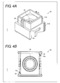
- Fig. 4A is a perspective view illustrating the configuration of the plunger body 31, and Fig. 4B is a plan view illustrating the configuration of the plunger body 31 when viewed from a lower side.
- a cam portion 34 (cam shape) to engage the contact mechanism 50 is formed in a lower portion 31 B of the plunger body 31.
- a hole 35 in which the light guide rod 42 can be inserted is made in a central portion of the plunger body 31.
- the cam portion 34 includes a concave-convex surface (cam shape) 34a that is formed in a concave-convex manner in a horizontal direction perpendicular to the Z-direction.
- Fig. 5 is a plan view illustrating the configuration of the contact mechanism 50 accommodated in the lower case 60 when viewed from an upper side.
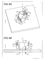
- Fig. 6A is a perspective view illustrating the configuration of the contact mechanism 50 provided on the board 7, and
- Fig. 6B is a side view illustrating the configuration of the contact mechanism 50.
- the contact mechanism 50 includes movable plates 51 and 52, fixed contacts 53 and 54, and movable contacts 55 and 56.
- the fixed contact 53 and the movable contact 55 are provided in the movable plate 51
- the fixed contact 54 and the movable contact 56 are provided in the movable plate 52.
- through-holes 7a are made in the board 7 in order to support the movable plates 51 and 52.
- the movable plates 51 and 52 include projected terminal portions 51 A and 52A (supports), which are connected to the outside while piercing the through-holes 7a.
- the movable plates 51 and 52 are supported by the board 7 with the projected terminal portions 51 A and 52A interposed therebetween.
- the movable plates 51 and 52 are made of a conductive material.
- the movable plates 51 and 52 include movable contact portions 51 B and 52B that are bent into a substantial L-shape from the projected terminal portions 51 A and 52A.
- abutment portions 51C and 52C abutting on the cam portion 34 of the plunger body 31 are provided in end portions on the sides opposite to the projected terminal portions 51 A and 52A.
- the abutment portions 51C and 52C have an outwardly-projected V-shape.
- apex portion 51 C 1 and 52C 1 of the V-shape abutment portions 51C and 52C abut on the concave-convex surface 34a of the cam portion 34.
- the movable contact portions 51 B and 52B are biased outward in the direction perpendicular to the Z-direction in the state in which the apex portion 51C 1 and 52C 1 of the abutment portions 51C and 52C abut on the concave-convex surface 34a.
- the movable contact portions 51 B and 52B act as leaf springs that are elastically deformed in the direction perpendicular to the Z-direction with the projected terminal portions 51 A and 52A as support points and with the abutment portions 51C and 52C as power points.
- the movable contact portions 51 B and 52B are disposed while bent in an outer peripheral space between the insertion pipe 62 and the sidewall 63.
- the bent portions of the movable contact portions 51 B and 52B are not limited to the bent configuration in which the plate (plate portion) is folded as illustrated in Figs. 5 and 6 .
- the bent portions may be constructed by curved surfaces that are formed by curvature of the plate (plate portion).
- fixed supports 51 D and 52D are formed in portions different from the portions in which the movable contact portions 51 B and 52B are provided in the projected terminal portions 51 A and 52A. Unlike the movable contact portions 51 B and 52B, the fixed supports 51 D and 52D are configured not to be deformed during the pressing motion of the switch.
- the fixed supports 51 D and 52D are formed as standing pieces that stand from the lower side below the movable contact portions 51 B and 52B, and the fixed supports 51 D and 52D include surfaces 51D 1 and 52D 1 extending in the Z-direction.
- the fixed contact 53 is attached to the surface 51D 1 of the fixed support 51 D.
- the movable contact 55 is attached to an outside surface of the movable contact portion 51 B.
- the fixed contact 54 is attached to the surface 52D 1 of the fixed support 52D.
- the movable contact 56 is attached to the outside surface of the movable contact portion 52B.
- each of the movable contact portions 51 B and 52B of the movable plates 51 and 52 is disposed while bent in the outer peripheral space between the insertion pipe 62 and the sidewalls 63 constituting the quadratic-prism lower case 60.
- the sidewalls 63 closest to the positions where the projected terminal portions 51 A and 52A are disposed differ from the sidewalls 63 closest to the positions where the abutment portions 51C and 52C coming into contact with the concave-convex surfaces 34a are disposed.
- the projected terminal portion 51 A of the movable plate 51 is disposed in a space of a corner portion I of the quadratic-prism lower case 60.
- the movable contact portion 51 B is disposed from the projected terminal portion 51 A along two sides I-IV and IV-III among four sides of a quadrangle formed by the sidewalls 63 of the lower case 60. That is, the movable contact portion 51 B extends from the projected terminal portion 51 A astride the corner portion IV.
- the abutment portion 51C which is the end portion on the side opposite to the projected terminal portion 51 A in the movable contact portion 51 B, is disposed in the space of the corner portion III.
- the projected terminal portion 52A of the movable plate 52 is disposed in the space of the corner portion III in the quadratic-prism lower case 60.
- the movable contact portion 52B is disposed from the projected terminal portion 52A along two sides III-II and II-I among the four sides of the quadrangle formed by the sidewalls 63 of the lower case 60. That is, the movable contact portion 52B extends from the projected terminal portion 52A astride the corner portion II.
- the abutment portion 52C which is the end portion on the side opposite to the projected terminal portion 52A in the movable contact portion 52B, is disposed in the space of the corner portion I.
- the fixed support 51 D is formed in a portion different from a portion in which the movable contact portion 51 B is provided in the projected terminal portion 51 A, and the fixed support 51 D is disposed in the space of the corner portion I.
- the fixed support 52D is formed in a portion different from a portion in which the movable contact portion 52B is provided in the projected terminal portion 52A, and the fixed support 52D is disposed in the space of the corner portion III.
- the movable plates 51 and 52 that are of the main structural elements in the contact mechanism 50 are disposed along the sidewalls 63 while avoiding the central space of the lower case 60.
- the movable plates 51 and 52 have not the cyclic shape disclosed in International Patent Publication No. 8-504050 , but have the plate shape.
- the movable contact portions 51 B and 52B are disposed while bent in the outer peripheral space between the insertion pipe 62 and the sidewalls 63 constituting the quadratic-prism lower case 60.
- the sidewalls 63 closest to the positions where the projected terminal portions 51 A and 52A are disposed differ from the sidewalls 63 closest to the positions where the abutment portions 51C and 52C coming into contact with the concave-convex surfaces 34a are disposed. Therefore, a distance between each of the projected terminal portions 51 A and 52A that are of the support points and each of the abutment portions 51C and 52C that are of the power points is lengthened, so that the force necessary to generate the elastic deformation of each of the movable contact portions 51 B and 52B can be reduced.
- the movable contact portions 51 B and 52B are configured to be bent along the sidewalls 63, so that the outer peripheral space between the insertion pipe 62 and the sidewalls 63 constituting the quadratic-prism lower case 60 can be reduced. Therefore, a volume of the central space can be enlarged without changing dimensions of the lower case 60 while the spaces for the movable plates 51 and 52 are reduced in the lower case 60.
- the space where the member is disposed can be ensured in the center of the lower case 60 without changing the dimension of the appearance of the switch.
- the light source 40 including the LED 41 and the light guide rod 42 is disposed in the ensured central space of the lower case 60. Therefore, the lighted push-button switch in which a button operating surface (the upper surface of the keytop 1) homogeneously emits light can be constructed without changing the dimensions of the appearance.
- the movable plates 51 and 52 have the axisymmetrically positional relationship with respect to a central axis O extending in the Z-direction when viewed from above.
- the movable plate 51 is disposed such that the movable contact 55 provided in the movable contact portion 51 B is opposed to the fixed contact 54 provided in the surface 52D 1 of the fixed support 52D in the movable plate 52.
- the movable plate 52 is disposed such that the movable contact 56 provided in the movable contact portion 52B is opposed to the fixed contact 53 provided in the surface 51D 1 of the fixed support 51 D in the movable plate 51.
- the contact mechanism 50 includes the two contact opening and closing mechanisms, so that contact reliability between the movable contact and fixed contact of the push-button switch 10 can be improved.
- the movable plate 51 and the movable plate 52 have the identical shape. Therefore, components of the movable plate 51 and the movable plate 52 can be shared with each other to reduce production cost.
- the movable plates 51 and 52 have the axisymmetrically positional relationship with respect to the central axis O extending in the Z-direction when viewed from above.
- a point at which the movable contact 55 and the fixed contact 54 are opened and closed and a point at which the movable contact 56 and the fixed contact 53 are opened and closed also have the axisymmetrically positional relationship with respect to the central axis O extending in the Z-direction. That is, the opening and closing unit constructed by the movable contact 55 and fixed contact 54 and the opening and closing unit constructed by the movable contact 56 and fixed contact 53 are axisymmetrical with respect to the central axis O.
- orientations of the forces applied to the two points at each of which the movable contact and the fixed contact are opened and closed become axisymmetrical with respect to the central axis O.
- the force is not applied to the plunger body 31 while biased toward one direction, but the force is evenly applied to the plunger body 31 in the direction perpendicular to the Z-direction.
- the plunger body 31 is not pressed while being in contact with a specific position of the upper case 20. As a result, abrasion of a specific portion of the plunger body 31 can be prevented to lengthen a lifetime of the switch.
- the light guide rod 42 is inserted in the communication pipe 61 of the lower case 60 to optically couple the LED 41 and the light guide rod 42 to each other.
- the helical spring 32 is inserted in the insertion pipe 62 of the lower case 60. At this point, the light guide rod 42 is accommodated in the helical spring 32.
- the plunger body 31 is attached to the lower case 60 from above the helical spring 32 such that the four corners of the plunger body 31 are accommodated in the four projected corner portions 64.
- the apex portions 51 C 1 and 52C 1 of the abutment portions 51C and 52C in the movable plates 51 and 52 abut on the concave-convex surface 34a of the cam portion 34 such that the movable contact portions 51 B and 52B are displaced outward. Therefore, the movable contact 55 provided in the movable contact portion 51 B is separated from the fixed contact 54 provided in the fixed support 52D.
- the movable contact 56 provided in the movable contact portion 52B is separated from the fixed contact 53 provided in the fixed support 51 D.
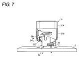
- FIG. 7 is a side view illustrating an engagement state between the plunger body 31 and the movable plate 51 before the operation of the push-button switch 10.
- Figs. 8A and 8C are sectional perspective views illustrating a process of operating the push-button switch 10
- Figs. 8B and 8D are partially enlarged views illustrating motions of the abutment portion 51C of the movable plate 51 and the cam portion 34 of the plunger body 31.
- the opening and closing motions of the movable contact 55 and fixed contact 54 by the pressing force in the push-button switch 10 will be described below. Because the opening and closing motions of the movable contact 56 and fixed contact 53 are similar to those of the movable contact 55 and fixed contact 54, the description is neglected.
- the upward force is applied to the lower portion 31 B of the plunger body 31 by the spring force of the helical spring 32, and therefore the plunger body 31 is biased upward.
- the abutment portion 51C of the movable plate 51 abuts on a convex surface 34a 1 of the concave-convex surface 34a of the cam portion 34 in the plunger body 31 with the apex portion 51C 1 interposed therebetween.
- the movable contact portion 51 B of the movable plate 51 abuts on the cam portion 34 with the abutment portion 51C interposed therebetween, the movable contact portion 51B is elastically deformed toward the inside in the direction (hereinafter referred to as the horizontal direction) perpendicular to the Z-direction.
- the horizontal direction perpendicular to the Z-direction.
- the cam portion 34 of the plunger body 31 abuts on the apex portion 51 C 1 of the abutment portion 51C of the movable plate 51 with the concave-convex surface 34a interposed therebetween, which latches the horizontally outward biasing force of the abutment portion 51C.
- the movable contact 55 provided in the movable contact portion 51 B is separated from the fixed contact 54 provided in the fixed support 52D.
- the cam portion 34 of the plunger body 31 has the shape having the concave-convex surface 34a that is formed in the concave-convex manner in the direction perpendicular to the Z-direction.
- the cam portion 34 of the plunger body 31 is not limited to the shape having the concave-convex surface 34a that is formed in the concave-convex manner in the direction perpendicular to the Z-direction.
- the cam portion 34 may be formed into any shape as long as the dimension in the horizontal direction perpendicular to the Z-direction varies in the Z-direction and as long as the shape generates the horizontal elastic deformation with respect to the movable contact portions 51 B and 52B.
- the cam portion 34 of the plunger body 31 may be formed into the shape including an inclination surface inclined with respect to the Z-direction. More specifically, the cam portion 34 may be formed into the shape having the inclination surface that is inclined so as to bulge inward from the upper side toward the lower side.
- the push-button switch 10 of the first embodiment includes the contact mechanism 50 including the opening and closing unit constructed by the movable contact 55 (movable contact 56) and the fixed contact 54 (fixed contact 53).
- the push-button switch 10 includes the lower case 60 having the quadratic-prism box shape and the plunger body 31 that is vertically movably attached to the quadratic prism in the axial direction (that is, the Z-direction) in the space of the lower case 60.
- the central space is defined by the communication pipe 61 and the insertion pipe 62.
- the plunger body 31 includes the cam portion 34 including the concave-convex surface 34a that is formed in the concave-convex manner in the horizontal direction perpendicular to the Z-direction.
- the contact mechanism 50 includes the movable plates 51 and 52 including the projected terminal portions 51 A and 52A supported by the lower case 60.
- the movable plates 51 and 52 include the movable contact portions 51 B and 52B in which the movable contacts 55 and 56 are provided, respectively.
- the movable contact portions 51 B and 52B abut on the concave-convex surface 34a to be elastically deformed in the horizontal direction in conjunction with the vertical motion of the plunger body 31. By the elastic deformations of the movable contact portions 51 B and 52B, the movable contacts 55 and 56 horizontally move to come into contact with or separate from the fixed contacts 54 and 53.
- the movable contact portions 51 B and 52B are disposed while bent in the outer peripheral space between the insertion pipe 62 and the sidewalls 63 constituting the quadratic-prism lower case 60, and the sidewalls 63 closest to the positions where the projected terminal portions 51 A and 52A are disposed differ from the sidewalls 63 closest to the positions where the portions (abutment portions 51C and 52C) coming into contact with the concave-convex surface 34a are disposed.
- the force in the Z-direction by the plunger body 31 is converted into the force in the horizontal direction perpendicular to the Z-direction to bring the movable contact 55 (movable contact 56) and the fixed contact 54 (fixed contact 53) into contact with each other or to separate the movable contact 55 and the fixed contact 54 from each other, thereby implementing the opening and closing of the electrical contact. Therefore, the dimension of the push-button switch 10 can be reduced in the Z-direction.
- the movable contact portions 51 B and 52B are disposed while bent in the outer peripheral space between the insertion pipe 62 and the sidewalls 63 constituting the quadratic-prism lower case 60, and the sidewalls 63 closest to the positions where the projected terminal portions 51 A and 52A are disposed differ from the sidewalls 63 closest to the positions where the portions (abutment portions 51C and 52C) coming into contact with the concave-convex surface 34a are disposed.
- the movable contact portions 51 B and 52B are configured to be bent along the sidewalls 63, so that the outer peripheral space between the insertion pipe 62 and the sidewalls 63 constituting the quadratic-prism lower case 60 can be reduced. As a result, the space where the member is disposed can be ensured in the center of the lower case 60 without changing the dimension of the appearance of the switch.
- the quadratic-prism corner portion I closest to the position where the projected terminal portion 51 A is disposed differs from the quadratic-prism corner portion III closest to the position where the portion (abutment portion 51 C) coming into contact with the concave-convex surface 34a is disposed.
- the quadratic-prism corner portion III closest to the position where the projected terminal portion 52A is disposed differs from the quadratic-prism corner portion I closest to the position where the portion (abutment portion 52C) coming into contact with the concave-convex surface 34a is disposed. Therefore, the distance between the projected terminal portions 51 A and 52A as the support points and "the portion coming into contact with the concave-convex surface 34a" as the power point can further be lengthened.
- the contact mechanism 50 includes the two movable plates 51 and 52 and the two opening and closing units corresponding to the movable plates 51 and 52. Therefore, the contact reliability between the movable contact and fixed contact of the switch can be improved.
- the two opening and closing units are disposed so as to be axisymmetrical with respect to the central axis of the Z-direction.
- the two opening and closing units are disposed so as to be axisymmetrical with respect to the central axis of the Z-direction, during the pressing operation of the push-button switch 10, the force is not applied to the plunger body 31 while biased toward one direction, but the force is evenly applied to the plunger body 31 in the direction perpendicular to the Z-direction. Therefore, the abrasion of the specific portion of the plunger body 31 can be prevented to lengthen the lifetime of the switch.
- the fixed supports 51 D and 52D are formed in the movable plates 51 and 52 in order to fix the fixed contacts 53 and 54, respectively.
- the fixed contact 53 provided in the fixed support 51 D of the movable plate 51 constitutes the first opening and closing unit together with the movable contact 56 provided in the movable contact portion 52B of the movable plate 52.
- the fixed contact 54 provided in the fixed support 52D of the movable plate 52 constitutes the second opening and closing unit together with the movable contact 55 provided in the movable contact portion 51 B of the movable plate 51.
- the movable contacts 55 and 56 and the fixed contacts 53 and 54 are provided in the movable plates 51 and 52, and the first opening and closing unit and the second opening and closing unit are constructed by the contacts provided in the movable plates 51 and 52 different from each other with respect to the movable contacts 55 and 56 and the fixed contacts 53 and 54.
- the number of components can be decreased, because the movable contacts 55 and 56 and the fixed contacts 53 and 54 are collectively provided in the movable plates 51 and 52 without separately providing the members used to move the movable contacts 55 and 56 and the members used to fix the fixed contacts 53 and 54.
- additionally the space where the member is disposed can be ensured in the center of the lower case 60.
- the light source 40 that emits the light upward in the Z-direction in the central space of the lower case 60.
- the light source 40 includes the LED 41 mounted on the board 7 and the light guide rod 42 optically coupled to the LED 41.
- the lighted push-button switch in which the button operating surface homogeneously emits the light can be constructed without changing the dimensions of the appearance.
- the abutment portions 51C and 52C abutting on the concave-convex surface 34a and the projected terminal portions 51 A and 52A are disposed in the spaces of the corner portions I to IV of the lower case 60.
- the abutment portions 51C and 52C abutting on the concave-convex surface 34a and the projected terminal portions 51 A and 52A are disposed in the spaces of the corner portions I to IV of the lower case 60 to effectively use the corner spaces of the lower case 60. Therefore, the space where the member is disposed can further be ensured in the center of the lower case 60.
- the upper case 20 and the lower case 60 have the quadratic-prism box shapes.
- the upper case 20 and the lower case 60 are not limited to the quadratic-prism box shapes, but the upper case 20 and the lower case 60 may have polygonal-column box shapes.
- each of the movable contact portions 51 B and 52B are configured to extend from each of the projected terminal portions 51 A and 52A along at least the two sidewalls 63 of the sidewalls 63 constituting the polygonal-column lower case 60. Therefore, the space where the member is disposed can be ensured in the center of the lower case 60 without changing the dimensions of the appearance of the switch.
- each of the movable contact portions 51 B and 52B may have the dimension extending along at least the two sidewalls 63 adjacent to each other, and the dimension can properly be set according to the elastic forces necessary to open and close the switch in the movable contact portions 51 B and 52B, the dimensions of the switch and the like.
- FIG. 9 is a sectional perspective view illustrating a configuration of the push-button switch 10 of the second embodiment. Fig. 9 illustrates the non-pressing state.
- the light source 40 including the LED 41 and the light guide rod 42 is disposed in the central space of the lower case 60, and the central space is ensured by the movable plates 51 and 52.
- the light source 40 disposed in the central space of the lower case 60 is not limited to the configuration including the light guide rod 42.
- the configuration of the light source 40 is properly set according to the dimensions of the push-button switch 10, and the like.
- the light source 40 may be constructed by a shell type LED 43 when being able to be accommodated in the central space of the lower case 60.
- the shell type LED 43 is accommodated in the communication pipe 61 formed in the substantial center of the lower case 60.
- the shell type LED 43 is attached to the board 7.
- the shell type LED 43 emits the light upward to irradiate the keytop 1.
- FIG. 10 is a sectional perspective view illustrating a configuration of the push-button switch 10 of the third embodiment.
- Fig. 10 illustrates the non-pressing state.
- the light source 40 emitting the light toward the keytop 1 is disposed in the central space of the lower case 60, and the central space is ensured by the movable plates 51 and 52.
- the member disposed in the central space of the lower case 60 is not limited to the light source, but the member may properly be set according to the dimension of the push-button switch 10, and the like.
- compact switches such as a tactile switch 44 may be provided as the member disposed in the central space of the lower case 60 when being able to be accommodated in the central space of the lower case 60.
- the tactile switch 44 is disposed immediately below the communication pipe 61 formed in the substantial center of the lower case 60.
- the tactile switch 44 is mounted on the board 7.
- a pressing shaft portion 1 a extending downward is formed in the central portion of the keytop 1.
- the pressing shaft portion 1a is inserted in the communication pipe 61 of the lower case 60 by the pressing operation of the push-button switch 10.
- the tactile switch 44 includes a button portion 44a on the upper side thereof. By the pressing operation of the push-button switch 10, the pressing shaft portion 1 a is inserted in the communication pipe 61 to come into contact with the button portion 44a, thereby turning on the tactile switch 44.
- the push-button switch 10 of the third embodiment when the upper portion 31 A of the plunger body 31 is pressed down to bring the movable contacts 55 and 56 into electrical contact with the fixed contacts 53 and 54, the pressing shaft portion 1 a of the keytop 1 is not in contact with the button portion 44a of the tactile switch 44. After the movable contacts 55 and 56 come into electrical contact with the fixed contacts 53 and 54, the pressing shaft portion 1 a is brought into contact with the button portion 44a by further pressing down a keytop 1', thereby turning on the tactile switch 44.
- the push-button switch 10 can be used as the two-stage switch.
- the tactile switch 44 that is of the compact switch is provided in the central space of the lower case 60, and the compact switch is configured such that the electric circuit is opened and closed after another electric circuit is turned on by the electrical contact between the movable contact 55 (movable contact 56) and the fixed contact 54 (fixed contact 53). Therefore, the push-button switch 10 can be used as a two-stage switch.
- the present invention relates to the contact type switch, particularly the present invention can be used as the switch incorporated in the keyboard, the industrial operation panel, the operation panel of the industrial video instrument and the consumer product.
Landscapes
- Push-Button Switches (AREA)
- Switch Cases, Indication, And Locking (AREA)
Abstract
Description
- The present invention relates to a switch, particularly to a push-button switch.
- Conventionally, for example, International Patent Publication No.
8-504050 Fig. 11 is an exploded perspective view illustrating a configuration of the flat key switch disclosed in International Patent Publication No. 8-504050. - As illustrated in
Fig. 11 , akey switch 100 of International Patent Publication No.8-504050 lower portion 110 and alid portion 120 covering thelower portion 110. Thekey switch 100 is opened and closed by switching between contact and non-contact of afixed contact piece 144 and acontact shoe 146. Thecontact shoe 146 is constructed by a cyclic thin-plate 150. When a push-rod 130 is pushed in, the cyclic thin-plate 150 is bent in a direction perpendicular to a direction, in which the push-rod 130 is pushed in, by an opening andclosing cam 140 provided in the push-rod 130. Thecontact shoe 146 constructed by the cyclic thin-plate 150 moves relative to thefixed contact piece 144 to come into contact with or separate (becomes the non-contact) from thefixed contact piece 144. Thus, thekey switch 100 of International Patent Publication No.8-504050 fixed contact piece 144 and thecontact shoe 146 in the direction perpendicular to the direction in which the push-rod 130 is pushed in. Therefore, thekey switch 100 is suitable for the switch in which an appearance has a flat structure. - However, in the key switch of International Patent Publication No.
8-504050 - In the
key switch 100 of International Patent Publication No.8-504050 contact shoe 146 constructed by the cyclic thin-plate 150 is disposed on a side of one of side surfaces constituting a quadratic prism of thelower portion 110. The cyclic thin-plate 150 has a cyclic structure because the cyclic thin-plate 150 is bent in the direction perpendicular to the direction in which the push-rod 130 is pushed in. Because a certain degree of flexibility is provided to the cyclic structure, the dimensions of the cyclic thin-plate 150 are enlarged in the direction perpendicular to the direction in which the push-rod 130 is pushed in. - Thus, a space of the
contact shoe 146 constructed by the cyclic thin-plate 150 is enlarged in the key switch of International Patent Publication No.8-504050 8-504050 - The present invention has been devised to solve the problems described above, and an object thereof is to provide a switch in which the space where the member is disposed can be ensured in the center without changing the dimensions of the appearance.
- In accordance with one aspect of the present invention, a switch includes: a contact mechanism that includes an opening and closing unit, the opening and closing unit including a movable contact and a fixed contact; a casing that is formed into a polygonal-column box shape, a central space of the casing being defined by an internal wall; and a pressing member that is attached while being vertically movable in an axial direction of the polygonal column in a space of the casing, the pressing member including a cam shape in which a dimension in a horizontal direction perpendicular to the axial direction varies in the axial direction. In the switch, the contact mechanism includes a plate-like member including a support supported by the casing, the plate-like member includes a movable contact portion in which the movable contact is provided, the movable contact portion abutting on the cam shape and being elastically deformed in the horizontal direction in conjunction with the vertical movement, the movable contact moves horizontally to come into contact with or separate from the fixed contact by an elastic deformation of the movable contact portion, the movable contact portion is disposed while bent in an outer peripheral space between the internal wall and sidewalls constituting the polygonal column, and the sidewall closest to a position where the support is disposed differs from the sidewall closest to a position where a portion coming into contact with the cam shape is disposed.
- According to the configuration, the contact mechanism includes the plate-like member that includes the support supported by the casing. The plate-like member includes the movable contact portion in which the movable contact is provided. In the pressing member, the movable contact portion abuts on the cam shape in which the dimension in the horizontal direction perpendicular to the axial direction varies in the axial direction. The movable contact portion is elastically deformed in the horizontal direction in conjunction with the vertical movement. In the contact mechanism, by the elastic deformation of the movable contact portion, the movable contact moves horizontally to come into contact with or separate from the fixed contact. In the switch, the force in the direction of the vertical movement by the pressing member is converted into the force in the horizontal direction perpendicular to the direction of the vertical movement, and the fixed contact and the movable contact are brought into contact with or separated from each other, thereby implementing the opening and closing of the electrical contact. Therefore, the dimension of the switch can be reduced in the direction of the vertical movement.
- According to the configuration, the movable contact portion is disposed while bent in the outer peripheral space between the internal wall and the sidewalls constituting the polygonal column, the sidewall closest to the position where the support is disposed differs from the sidewall closest to the position where the portion coming into contact with the cam shape is disposed. Therefore, a distance between the support that is of a support point and "the portion coming into contact with the cam shape" that is of a power point is lengthened, so that the force necessary to generate the elastic deformation of the movable contact portion can be reduced. As to a technique of lengthening the support point (the support) and the power point (the portion coming into contact with the cam shape), for example, the movable contact portion is configured to be bent along the sidewall, so that the outer peripheral space between the internal wall and the sidewalls constituting the polygonal column can be reduced. As a result, a volume of the central space can be enlarged without changing the dimensions of the casing. Therefore, according to the configuration, the space where the member is disposed can be ensured in the center of the casing without changing the dimensions of the appearance of the switch.
- In the switch, preferably, in the polygonal column, a corner portion closest to the position where the support is disposed differs from a corner portion closest to the position where the portion coming into contact with the cam shape is disposed. Therefore, the distance between the support that is of the support point and "the portion coming into contact with the cam shape" that is of the power point can further be lengthened.
- In the pressing member of the switch of the present invention, any "cam shape" may be used as long as the dimension in the horizontal direction perpendicular to the axial direction varies in the axial direction and as long as the elastic deformation is horizontally generated in the movable contact portion. A shape having a concave-convex surface horizontally formed in a concave-convex manner and a shape having an inclination surface inclined with respect to the axial direction can be cited as an example of the "cam shape".
- In the switch, preferably the contact mechanism includes the two plate-like members and the two opening and closing units corresponding to the two plate-like members, respectively.
- According to the configuration, the contact mechanism includes the two plate-like members and the two opening and closing units corresponding to the two plate-like members, respectively, so that contact reliability can be improved between the movable contact and fixed contact of the switch.
- In the switch, preferably the two opening and closing units are disposed so as to become axisymmetrical with respect to a central axis of a direction of the vertical movement.
- According to the configuration, because the two opening and closing units are disposed so as to become axisymmetrical with respect to the central axis of the direction of the vertical movement, during a pressing operation of the switch, the force is not applied to the pressing member while biased toward one direction, but the force is evenly applied to the pressing member in the direction perpendicular to the vertical movement. Therefore, abrasion can be prevented in a specific portion of the pressing member to lengthen a lifetime of the switch.
- In the switch, preferably a fixed support configured to fix the fixed contact is formed in each plate-like member, in the two plate-like members, the fixed contact provided in the fixed support of a first plate-like member and the movable contact provided in the movable contact portion of a second plate-like member constitute a first opening and closing unit, and the fixed contact provided in the fixed support of the second plate-like member and the movable contact provided in the movable contact portion of the first plate-like member constitute a second opening and closing unit.
- According to the configuration, the movable contact and the fixed contact are provided in each plate-like member, and the first opening and closing unit and the second opening and closing unit are constructed by the contacts included in the plate-like members different from each other with respect to the movable contacts and the fixed contacts. According to the configuration, the number of components can be decreased, because the movable contact and the fixed contact are collectively provided in the one movable plate without separately providing the member used to move the movable contact and the member used to fix the fixed contact. As a result, the space where the member is disposed can be ensured in the center of the casing.
- In the switch, preferably a light source configured to emit light upward in the direction of the vertical movement is provided in the central space of the casing.
- According to the configuration, the light source that emits the light upward in the direction of the vertical movement is provided in the central space of the casing ensured in the above manner. Therefore, the lighted push-button switch in which the button operating surface is homogeneously illuminated can be constructed without changing the dimensions of the appearance.
- In the switch, the light source may include an LED mounted on a board and a light guide rod optically coupled to the LED.
- In the switch, the light source may include a shell type LED. Therefore, use efficiency of the light can be improved.
- In the switch, preferably a compact switch is provided in the central space of the casing, and the compact switch is configured to open and close an electric circuit after another electric circuit is turned on by electrical contact between the movable contact and the fixed contact.
- According to the configuration, the compact switch is provided in the central space of the casing ensured in the above manner. The compact switch is configured to open and close the electric circuit after another electric circuit is turned on by the electrical contact between the movable contact and the fixed contact, so that the switch of the present invention can be used as a two-stage switch.
- In the switch, preferably, in the plate-like member, an abutment portion abutting on the cam shape and the support are disposed in a corner space of the casing.
- According to the configuration, in the plate-like member, the abutment portion abutting on the cam shape and the support are disposed in the corner space of the casing, and the corner space of the casing is effectively used. Therefore, the space where the member is disposed can further be ensured in the center of the casing.
- As described above, in one aspect of the present invention, the switch includes: the casing that is formed into the polygonal-column box shape, the central space of the casing being defined by the internal wall; and the pressing member that is attached while being vertically movable in the axial direction of the polygonal column in the space of the casing, the pressing member including the cam shape in which the dimension in the horizontal direction perpendicular to the axial direction varies in the axial direction. In the switch, the contact mechanism includes the plate-like member including the support supported by the casing, the plate-like member includes the movable contact portion in which the movable contact is provided, the movable contact portion abutting on the cam shape and being elastically deformed in the horizontal direction in conjunction with the vertical movement, the movable contact moves horizontally to come into contact with or separate from the fixed contact by the elastic deformation of the movable contact portion, the movable contact portion is disposed while bent in the outer peripheral space between the internal wall and sidewalls constituting the polygonal column, and the sidewall closest to the position where the support is disposed differs from the sidewall closest to the position where the portion coming into contact with the cam shape is disposed.
- Therefore, according to the present invention, advantageously the space where the member is disposed can be ensured in the center without changing the dimensions of the appearance.
-
-
Fig. 1 is an exploded perspective view illustrating a configuration of a push-button switch according to a first embodiment of the present invention; -
Fig. 2 is a perspective view illustrating an appearance of the push-button switch; -
Fig. 3 is a sectional perspective view illustrating the configuration of the push-button switch; -
Fig. 4A is a perspective view illustrating a configuration of a plunger body in the push-button switch illustrated inFigs 1 to 3 , andFig. 4B is a plan view illustrating the configuration of the plunger body when viewed from a lower side; -
Fig. 5 is a plan view illustrating a configuration of a contact mechanism accommodated in a lower case in the push-button switch illustrated inFigs 1 to 3 when viewed from an upper side; -
Fig. 6A is a perspective view illustrating the configuration of the contact mechanism provided on a board in the push-button switch illustrated inFigs 1 to 3 , andFig. 6B is a side view illustrating the configuration of the contact mechanism; -
Fig. 7 is a side view illustrating an engagement state between the plunger body and a movable plate before operation of the push-button switch illustrated inFigs 1 to 3 ; -
Figs. 8A and 8C are sectional perspective views illustrating an operating process of the push-button switch illustrated inFigs 1 to 3 , andFigs. 8B and 8D are partially enlarged views illustrating motions of an abutment portion of a movable plate and a cam portion of the plunger body; -
Fig. 9 is a sectional perspective view illustrating a configuration of a push-button switch according to a second embodiment of the present invention; -
Fig. 10 is a sectional perspective view illustrating a configuration of a push-button switch according to a third embodiment of the present invention; and -
Fig. 11 is an exploded perspective view illustrating a configuration of a flat key switch disclosed in International Patent Publication No.8-504050 -
- Hereinafter, embodiments of the present invention will be described with reference to the drawings.
Fig. 1 is an exploded perspective view illustrating a configuration of a push-button switch 10 according to a first embodiment.Fig. 2 is a perspective view illustrating an appearance of the push-button switch 10.Fig. 3 is a sectional perspective view illustrating the configuration of the push-button switch 10.Figs. 2 and 3 illustrate a non-pressing state. - The push-
button switch 10 of the first embodiment is a contact type switch, and has the configuration particularly suitable for a lighted switch assembled in a keyboard, an industrial operation panel, an operation panel of a business-use video instrument, and a consumer product. - As illustrated in
Figs. 1 to 3 , the push-button switch 10 includes akeytop 1, an upper case 20 (casing), aplunger unit 30, a light source 40, acontact mechanism 50, a lower case 60 (casing), and aboard 7. Theupper case 20 is fitted in thelower case 60 to cover thecontact mechanism 50 and support theplunger unit 30 such that theplunger unit 30 is vertically movable. The light source 40 includes anLED 41 and alight guide rod 42. As illustrated inFig. 3 , theLED 41 is mounted on theboard 7. Theplunger unit 30 includes a plunger body (push-in member) 31 and ahelical spring 32. At this point, a direction in which the push-button switch is pushed in is assumed to be a Z-direction. In the Z-direction, a side of thekeytop 1 is assumed to be an upper side, and a side of theboard 7 is assumed to be a lower side. - A
hole 21 in which anupper portion 31 A of theplunger body 31 can be inserted is made in theupper case 20. Anengagement groove 33 to engage thekeytop 1 is formed in theupper portion 31 A of theplunger body 31. Therefore, theupper portion 31 A of theplunger body 31 engages thekeytop 1 while inserted in thehole 21 of theupper case 20. - The
lower case 60 has a quadratic-prism box shape, and is attached to theboard 7 as illustrated inFig. 1 . When viewed from above, a communication pipe 61 (internal wall) communicated to theboard 7 is formed in a substantial center of thelower case 60. The light source 40 is accommodated in thecommunication pipe 61. Specifically, theLED 41 mounted on theboard 7 is disposed immediately above thecommunication pipe 61. Thelight guide rod 42 is inserted in thecommunication pipe 61, and supported in a predetermined position by engagement between a latchingportion 42a and acommunication pipe 61. Light from theLED 41 is coupled to thelight guide rod 42, is guided in thelight guide rod 42, and exits upward. - An insertion pipe 62 (internal wall) is formed in the
lower case 60 so as to surround thecommunication pipe 61. Theinsertion pipe 62 is configured to neither pierce a bottom surface of thelower case 60 nor be communicated to theboard 7. Thehelical spring 32 of the plunger unit 3 is accommodated in a space between an outer wall of thecommunication pipe 61 and an inner wall of theinsertion pipe 62. That is, in thelower case 60, a central space is defined by thecommunication pipe 61 and theinsertion pipe 62. Thecontact mechanism 50 is accommodated in a space (outer peripheral space) surrounded by an outer wall (internal wall) of theinsertion pipe 62 and asidewall 63 of thelower case 60. - When viewed from above, a projected
corner portion 64 that is projected upward while a shape of the corner portion is maintained is formed in each rectangular corner portion formed by thesidewalls 63. A lower portion of theplunger body 31 of theplunger unit 30 has a shape that can be supported by the four projectedcorner portions 64. In pressing the push-button switch 10, the projectedcorner portion 64 acts as a guide portion that guides theplunger body 31 downward. Theplunger body 31 is disposed while being in contact with the upper portion of thehelical spring 32. Thehelical spring 32 is accommodated in thelower case 60 such that an elastic force acts in a direction opposite to a pressing force when theplunger body 31 is pressed. -
Fig. 4A is a perspective view illustrating the configuration of theplunger body 31, andFig. 4B is a plan view illustrating the configuration of theplunger body 31 when viewed from a lower side. As illustrated inFigs. 4A and 4B , a cam portion 34 (cam shape) to engage thecontact mechanism 50 is formed in alower portion 31 B of theplunger body 31. Ahole 35 in which thelight guide rod 42 can be inserted is made in a central portion of theplunger body 31. As illustrated inFig. 4B , thecam portion 34 includes a concave-convex surface (cam shape) 34a that is formed in a concave-convex manner in a horizontal direction perpendicular to the Z-direction. - The configuration of the
contact mechanism 50 will be described in detail with reference toFigs. 5 ,6A , and6B .Fig. 5 is a plan view illustrating the configuration of thecontact mechanism 50 accommodated in thelower case 60 when viewed from an upper side.Fig. 6A is a perspective view illustrating the configuration of thecontact mechanism 50 provided on theboard 7, andFig. 6B is a side view illustrating the configuration of thecontact mechanism 50. - As illustrated in
Figs. 5 ,6A, and 6B , thecontact mechanism 50 includesmovable plates contacts movable contacts contact 53 and themovable contact 55 are provided in themovable plate 51, and the fixedcontact 54 and themovable contact 56 are provided in themovable plate 52. As illustrated inFig. 6A , through-holes 7a are made in theboard 7 in order to support themovable plates movable plates terminal portions holes 7a. Themovable plates board 7 with the projectedterminal portions movable plates - When viewed from above, the
movable plates movable contact portions terminal portions movable contact portions abutment portions cam portion 34 of theplunger body 31 are provided in end portions on the sides opposite to the projectedterminal portions abutment portions button switch 10,apex portion shape abutment portions convex surface 34a of thecam portion 34. Themovable contact portions apex portion abutment portions convex surface 34a. During a pressing motion of the switch, themovable contact portions terminal portions abutment portions - Thus, the
movable contact portions insertion pipe 62 and thesidewall 63. The bent portions of themovable contact portions Figs. 5 and6 . Alternatively, for example, the bent portions may be constructed by curved surfaces that are formed by curvature of the plate (plate portion). - In the
movable plates movable contact portions terminal portions movable contact portions movable contact portions surfaces - In the
movable plate 51, the fixedcontact 53 is attached to thesurface 51D1 of the fixedsupport 51 D. Themovable contact 55 is attached to an outside surface of themovable contact portion 51 B. In themovable plate 52, the fixedcontact 54 is attached to thesurface 52D1 of the fixedsupport 52D. Themovable contact 56 is attached to the outside surface of themovable contact portion 52B. - A positional relationship between the
movable plates lower case 60 will be described below. As illustrated inFig. 5 , each of themovable contact portions movable plates insertion pipe 62 and thesidewalls 63 constituting the quadratic-prismlower case 60. The sidewalls 63 closest to the positions where the projectedterminal portions sidewalls 63 closest to the positions where theabutment portions convex surfaces 34a are disposed. - As illustrated in
Fig. 5 , the projectedterminal portion 51 A of themovable plate 51 is disposed in a space of a corner portion I of the quadratic-prismlower case 60. Themovable contact portion 51 B is disposed from the projectedterminal portion 51 A along two sides I-IV and IV-III among four sides of a quadrangle formed by thesidewalls 63 of thelower case 60. That is, themovable contact portion 51 B extends from the projectedterminal portion 51 A astride the corner portion IV. Theabutment portion 51C, which is the end portion on the side opposite to the projectedterminal portion 51 A in themovable contact portion 51 B, is disposed in the space of the corner portion III. The projectedterminal portion 52A of themovable plate 52 is disposed in the space of the corner portion III in the quadratic-prismlower case 60. Themovable contact portion 52B is disposed from the projectedterminal portion 52A along two sides III-II and II-I among the four sides of the quadrangle formed by thesidewalls 63 of thelower case 60. That is, themovable contact portion 52B extends from the projectedterminal portion 52A astride the corner portion II. Theabutment portion 52C, which is the end portion on the side opposite to the projectedterminal portion 52A in themovable contact portion 52B, is disposed in the space of the corner portion I. - The fixed
support 51 D is formed in a portion different from a portion in which themovable contact portion 51 B is provided in the projectedterminal portion 51 A, and the fixedsupport 51 D is disposed in the space of the corner portion I. The fixedsupport 52D is formed in a portion different from a portion in which themovable contact portion 52B is provided in the projectedterminal portion 52A, and the fixedsupport 52D is disposed in the space of the corner portion III. - According to the configuration of the push-
button switch 10, themovable plates contact mechanism 50 are disposed along thesidewalls 63 while avoiding the central space of thelower case 60. Themovable plates 8-504050 movable contact portions insertion pipe 62 and thesidewalls 63 constituting the quadratic-prismlower case 60. The sidewalls 63 closest to the positions where the projectedterminal portions sidewalls 63 closest to the positions where theabutment portions convex surfaces 34a are disposed. Therefore, a distance between each of the projectedterminal portions abutment portions movable contact portions movable contact portions sidewalls 63, so that the outer peripheral space between theinsertion pipe 62 and thesidewalls 63 constituting the quadratic-prismlower case 60 can be reduced. Therefore, a volume of the central space can be enlarged without changing dimensions of thelower case 60 while the spaces for themovable plates lower case 60. - As a result, in the configuration of the push-
button switch 10, the space where the member is disposed can be ensured in the center of thelower case 60 without changing the dimension of the appearance of the switch. - As illustrated in
Figs. 1 to 3 , in the push-button switch 10 of the first embodiment, the light source 40 including theLED 41 and thelight guide rod 42 is disposed in the ensured central space of thelower case 60. Therefore, the lighted push-button switch in which a button operating surface (the upper surface of the keytop 1) homogeneously emits light can be constructed without changing the dimensions of the appearance. - The positional relationship between the
movable plates contact mechanism 50 will be described below. As illustrated inFigs. 5 ,6A, and 6b , themovable plates - The
movable plate 51 is disposed such that themovable contact 55 provided in themovable contact portion 51 B is opposed to the fixedcontact 54 provided in thesurface 52D1 of the fixedsupport 52D in themovable plate 52. On the other hand, themovable plate 52 is disposed such that themovable contact 56 provided in themovable contact portion 52B is opposed to the fixedcontact 53 provided in thesurface 51D1 of the fixedsupport 51 D in themovable plate 51. - In the push-
button switch 10, electrical contact between themovable contact 55 provided in themovable plate 51 and the fixedcontact 54 provided in themovable plate 52 and electrical contact between themovable contact 56 provided in themovable plate 52 and the fixedcontact 53 provided in themovable plate 51 are opened and closed. Thecontact mechanism 50 includes the two contact opening and closing mechanisms, so that contact reliability between the movable contact and fixed contact of the push-button switch 10 can be improved. Themovable plate 51 and themovable plate 52 have the identical shape. Therefore, components of themovable plate 51 and themovable plate 52 can be shared with each other to reduce production cost. - In the push-
button switch 10, themovable plates movable contact 55 and the fixedcontact 54 are opened and closed and a point at which themovable contact 56 and the fixedcontact 53 are opened and closed also have the axisymmetrically positional relationship with respect to the central axis O extending in the Z-direction. That is, the opening and closing unit constructed by themovable contact 55 and fixedcontact 54 and the opening and closing unit constructed by themovable contact 56 and fixedcontact 53 are axisymmetrical with respect to the central axis O. When the push-button switch 10 is pressed to open and close the electrical contact, orientations of the forces applied to the two points at each of which the movable contact and the fixed contact are opened and closed become axisymmetrical with respect to the central axis O. During the pressing operation of the push-button switch 10, the force is not applied to theplunger body 31 while biased toward one direction, but the force is evenly applied to theplunger body 31 in the direction perpendicular to the Z-direction. For example, theplunger body 31 is not pressed while being in contact with a specific position of theupper case 20. As a result, abrasion of a specific portion of theplunger body 31 can be prevented to lengthen a lifetime of the switch. - An example of a method for assembling the push-
button switch 10 will be described below. First thelower case 60 in which thecontact mechanism 50 is assembled is attached to theboard 7 on which theLED 41 is mounted. - Then the
light guide rod 42 is inserted in thecommunication pipe 61 of thelower case 60 to optically couple theLED 41 and thelight guide rod 42 to each other. Then thehelical spring 32 is inserted in theinsertion pipe 62 of thelower case 60. At this point, thelight guide rod 42 is accommodated in thehelical spring 32. - Then the
plunger body 31 is attached to thelower case 60 from above thehelical spring 32 such that the four corners of theplunger body 31 are accommodated in the four projectedcorner portions 64. At this point, theapex portions abutment portions movable plates convex surface 34a of thecam portion 34 such that themovable contact portions movable contact 55 provided in themovable contact portion 51 B is separated from the fixedcontact 54 provided in the fixedsupport 52D. Themovable contact 56 provided in themovable contact portion 52B is separated from the fixedcontact 53 provided in the fixedsupport 51 D. - Then the
upper case 20 and thekeytop 1 are sequentially attached to complete the push-button switch 10. - A method for operating the push-
button switch 10 will be described below.Fig. 7 is a side view illustrating an engagement state between theplunger body 31 and themovable plate 51 before the operation of the push-button switch 10.Figs. 8A and 8C are sectional perspective views illustrating a process of operating the push-button switch 10, andFigs. 8B and 8D are partially enlarged views illustrating motions of theabutment portion 51C of themovable plate 51 and thecam portion 34 of theplunger body 31. The opening and closing motions of themovable contact 55 and fixedcontact 54 by the pressing force in the push-button switch 10 will be described below. Because the opening and closing motions of themovable contact 56 and fixedcontact 53 are similar to those of themovable contact 55 and fixedcontact 54, the description is neglected. - As illustrated in
Figs. 7 and8A , before the operation of the push-button switch 10, the upward force is applied to thelower portion 31 B of theplunger body 31 by the spring force of thehelical spring 32, and therefore theplunger body 31 is biased upward. Before the operation of the push-button switch 10, theabutment portion 51C of themovable plate 51 abuts on aconvex surface 34a1 of the concave-convex surface 34a of thecam portion 34 in theplunger body 31 with theapex portion 51C1 interposed therebetween. - At this point, because the
movable contact portion 51 B of themovable plate 51 abuts on thecam portion 34 with theabutment portion 51C interposed therebetween, themovable contact portion 51B is elastically deformed toward the inside in the direction (hereinafter referred to as the horizontal direction) perpendicular to the Z-direction. Thus, before the operation of the push-button switch 10, the horizontally outward force is applied to theabutment portion 51C of themovable plate 51 by the elastic force of themovable contact portion 51 B. Therefore, theabutment portion 51C is biased toward the horizontally outward direction. That is, theabutment portion 51C presses thecam portion 34 outward. Thecam portion 34 of theplunger body 31 abuts on theapex portion 51 C1 of theabutment portion 51C of themovable plate 51 with the concave-convex surface 34a interposed therebetween, which latches the horizontally outward biasing force of theabutment portion 51C. At this point, themovable contact 55 provided in themovable contact portion 51 B is separated from the fixedcontact 54 provided in the fixedsupport 52D. - As illustrated in
Fig. 8C , when theupper portion 31 A of theplunger body 31 is pushed down, thehelical spring 32 is bent, and theapex portion 51 C1 of theabutment portion 51C slides on the concave-convex surface 34a of thecam portion 34 while being biased toward the horizontally outward direction. When theupper portion 31 A of theplunger body 31 is pushed down and theabutment portion 51C of themovable plate 51 is positioned above thecam portion 34, thecam portion 34 releases the operation to latch the horizontally outward biasing force of theabutment portion 51C. At this point, themovable contact 55 provided in themovable contact portion 51 B comes into electrical contact with the fixedcontact 54 provided in the fixedsupport 52D. - When the
plunger body 31 releases the pressing force applied to theupper portion 31 A, thehelical spring 32 pushes up theplunger body 31. At this point, theabutment portion 51C slides on the concave-convex surface 34a of thecam portion 34 of theplunger body 31. Then theabutment portion 51C is latched in theconvex surface 34a1 of the concave-convex surface 34a. Therefore, theplunger body 31 and themovable plate 51 returns to the positions before the operation of the push-button switch 10. - In the push-
button switch 10, thecam portion 34 of theplunger body 31 has the shape having the concave-convex surface 34a that is formed in the concave-convex manner in the direction perpendicular to the Z-direction. However, thecam portion 34 of theplunger body 31 is not limited to the shape having the concave-convex surface 34a that is formed in the concave-convex manner in the direction perpendicular to the Z-direction. Thecam portion 34 may be formed into any shape as long as the dimension in the horizontal direction perpendicular to the Z-direction varies in the Z-direction and as long as the shape generates the horizontal elastic deformation with respect to themovable contact portions cam portion 34 of theplunger body 31 may be formed into the shape including an inclination surface inclined with respect to the Z-direction. More specifically, thecam portion 34 may be formed into the shape having the inclination surface that is inclined so as to bulge inward from the upper side toward the lower side. - The push-
button switch 10 of the first embodiment includes thecontact mechanism 50 including the opening and closing unit constructed by the movable contact 55 (movable contact 56) and the fixed contact 54 (fixed contact 53). The push-button switch 10 includes thelower case 60 having the quadratic-prism box shape and theplunger body 31 that is vertically movably attached to the quadratic prism in the axial direction (that is, the Z-direction) in the space of thelower case 60. In thelower case 60, the central space is defined by thecommunication pipe 61 and theinsertion pipe 62. Theplunger body 31 includes thecam portion 34 including the concave-convex surface 34a that is formed in the concave-convex manner in the horizontal direction perpendicular to the Z-direction. Thecontact mechanism 50 includes themovable plates terminal portions lower case 60. Themovable plates movable contact portions movable contacts movable contact portions convex surface 34a to be elastically deformed in the horizontal direction in conjunction with the vertical motion of theplunger body 31. By the elastic deformations of themovable contact portions movable contacts contacts button switch 10, themovable contact portions insertion pipe 62 and thesidewalls 63 constituting the quadratic-prismlower case 60, and thesidewalls 63 closest to the positions where the projectedterminal portions sidewalls 63 closest to the positions where the portions (abutment portions convex surface 34a are disposed. - In the push-
button switch 10, the force in the Z-direction by theplunger body 31 is converted into the force in the horizontal direction perpendicular to the Z-direction to bring the movable contact 55 (movable contact 56) and the fixed contact 54 (fixed contact 53) into contact with each other or to separate themovable contact 55 and the fixedcontact 54 from each other, thereby implementing the opening and closing of the electrical contact. Therefore, the dimension of the push-button switch 10 can be reduced in the Z-direction. - At this point, the
movable contact portions insertion pipe 62 and thesidewalls 63 constituting the quadratic-prismlower case 60, and thesidewalls 63 closest to the positions where the projectedterminal portions sidewalls 63 closest to the positions where the portions (abutment portions convex surface 34a are disposed. Therefore, the distance between each of the projectedterminal portions convex surface 34a" that is of the power point is lengthened, so that the force necessary to generate the elastic deformation of each of themovable contact portions terminal portions convex surface 34a), for example, themovable contact portions sidewalls 63, so that the outer peripheral space between theinsertion pipe 62 and thesidewalls 63 constituting the quadratic-prismlower case 60 can be reduced. As a result, the space where the member is disposed can be ensured in the center of thelower case 60 without changing the dimension of the appearance of the switch. - In the push-
button switch 10, the quadratic-prism corner portion I closest to the position where the projectedterminal portion 51 A is disposed differs from the quadratic-prism corner portion III closest to the position where the portion (abutment portion 51 C) coming into contact with the concave-convex surface 34a is disposed. The quadratic-prism corner portion III closest to the position where the projectedterminal portion 52A is disposed differs from the quadratic-prism corner portion I closest to the position where the portion (abutment portion 52C) coming into contact with the concave-convex surface 34a is disposed. Therefore, the distance between the projectedterminal portions convex surface 34a" as the power point can further be lengthened. - In the push-
button switch 10, thecontact mechanism 50 includes the twomovable plates movable plates - In the push-
button switch 10, the two opening and closing units are disposed so as to be axisymmetrical with respect to the central axis of the Z-direction. - Because the two opening and closing units are disposed so as to be axisymmetrical with respect to the central axis of the Z-direction, during the pressing operation of the push-
button switch 10, the force is not applied to theplunger body 31 while biased toward one direction, but the force is evenly applied to theplunger body 31 in the direction perpendicular to the Z-direction. Therefore, the abrasion of the specific portion of theplunger body 31 can be prevented to lengthen the lifetime of the switch. - In the push-
button switch 10, the fixed supports 51 D and 52D are formed in themovable plates contacts movable plates contact 53 provided in the fixedsupport 51 D of themovable plate 51 constitutes the first opening and closing unit together with themovable contact 56 provided in themovable contact portion 52B of themovable plate 52. The fixedcontact 54 provided in the fixedsupport 52D of themovable plate 52 constitutes the second opening and closing unit together with themovable contact 55 provided in themovable contact portion 51 B of themovable plate 51. - According to the configuration, the
movable contacts contacts movable plates movable plates movable contacts contacts movable contacts contacts movable plates movable contacts contacts lower case 60. - In the push-
button switch 10, the light source 40 that emits the light upward in the Z-direction in the central space of thelower case 60. The light source 40 includes theLED 41 mounted on theboard 7 and thelight guide rod 42 optically coupled to theLED 41. - By providing the light source 40 that emits the light upward in the Z-direction in the secured central space of the
lower case 60, the lighted push-button switch in which the button operating surface homogeneously emits the light can be constructed without changing the dimensions of the appearance. - In the
movable plates button switch 10, theabutment portions convex surface 34a and the projectedterminal portions lower case 60. - Therefore, in the
movable plates abutment portions convex surface 34a and the projectedterminal portions lower case 60 to effectively use the corner spaces of thelower case 60. Therefore, the space where the member is disposed can further be ensured in the center of thelower case 60. - In the configuration of
Figs. 1 to 3 , theupper case 20 and thelower case 60 have the quadratic-prism box shapes. Theupper case 20 and thelower case 60 are not limited to the quadratic-prism box shapes, but theupper case 20 and thelower case 60 may have polygonal-column box shapes. Even if theupper case 20 and thelower case 60 have the polygonal-column box shapes, each of themovable contact portions terminal portions sidewalls 63 of thesidewalls 63 constituting the polygonal-columnlower case 60. Therefore, the space where the member is disposed can be ensured in the center of thelower case 60 without changing the dimensions of the appearance of the switch. - In the
movable plates movable contact portions sidewalls 63 adjacent to each other, and the dimension can properly be set according to the elastic forces necessary to open and close the switch in themovable contact portions - A second embodiment of the present invention will be described below with reference to
Fig. 9 . For the sake of convenience, the member having the same function as that of the member of the first embodiment is designated by the same numeral, and the description is neglected.Fig. 9 is a sectional perspective view illustrating a configuration of the push-button switch 10 of the second embodiment.Fig. 9 illustrates the non-pressing state. - In the push-
button switch 10 of the first embodiment, the light source 40 including theLED 41 and thelight guide rod 42 is disposed in the central space of thelower case 60, and the central space is ensured by themovable plates lower case 60 is not limited to the configuration including thelight guide rod 42. The configuration of the light source 40 is properly set according to the dimensions of the push-button switch 10, and the like. For example, the light source 40 may be constructed by ashell type LED 43 when being able to be accommodated in the central space of thelower case 60. - As illustrated in
Fig. 9 , in the push-button switch 10 of the second embodiment, theshell type LED 43 is accommodated in thecommunication pipe 61 formed in the substantial center of thelower case 60. Theshell type LED 43 is attached to theboard 7. Theshell type LED 43 emits the light upward to irradiate thekeytop 1. - According to the push-
button switch 10 of the second embodiment, use efficiency of the light emitted from theshell type LED 43 can be improved because necessity of thelight guide rod 42 used in the optical coupling is eliminated. - A third embodiment of the present invention will be described below with reference to
Fig. 10 . For the sake of convenience, the member having the same function as that of the member of the first embodiment is designated by the same numeral, and the description is neglected.Fig. 10 is a sectional perspective view illustrating a configuration of the push-button switch 10 of the third embodiment.Fig. 10 illustrates the non-pressing state. - In the push-
button switch 10 of the first and second embodiments, the light source 40 emitting the light toward thekeytop 1 is disposed in the central space of thelower case 60, and the central space is ensured by themovable plates lower case 60 is not limited to the light source, but the member may properly be set according to the dimension of the push-button switch 10, and the like. For example, compact switches such as atactile switch 44 may be provided as the member disposed in the central space of thelower case 60 when being able to be accommodated in the central space of thelower case 60. - As illustrated in
Fig. 10 , in the push-button switch 10 of the third embodiment, thetactile switch 44 is disposed immediately below thecommunication pipe 61 formed in the substantial center of thelower case 60. Thetactile switch 44 is mounted on theboard 7. Apressing shaft portion 1 a extending downward is formed in the central portion of thekeytop 1. Thepressing shaft portion 1a is inserted in thecommunication pipe 61 of thelower case 60 by the pressing operation of the push-button switch 10. Thetactile switch 44 includes abutton portion 44a on the upper side thereof. By the pressing operation of the push-button switch 10, thepressing shaft portion 1 a is inserted in thecommunication pipe 61 to come into contact with thebutton portion 44a, thereby turning on thetactile switch 44. - In the push-
button switch 10 of the third embodiment, when theupper portion 31 A of theplunger body 31 is pressed down to bring themovable contacts contacts pressing shaft portion 1 a of thekeytop 1 is not in contact with thebutton portion 44a of thetactile switch 44. After themovable contacts contacts pressing shaft portion 1 a is brought into contact with thebutton portion 44a by further pressing down a keytop 1', thereby turning on thetactile switch 44. According to the third embodiment, the push-button switch 10 can be used as the two-stage switch. - In the push-
button switch 10 of the third embodiment, thetactile switch 44 that is of the compact switch is provided in the central space of thelower case 60, and the compact switch is configured such that the electric circuit is opened and closed after another electric circuit is turned on by the electrical contact between the movable contact 55 (movable contact 56) and the fixed contact 54 (fixed contact 53). Therefore, the push-button switch 10 can be used as a two-stage switch. - The present invention is not limited to the above embodiments, but various changes can be made without departing from the scope of claims of the present invention. An embodiment obtained by properly combining the different technical means disclosed in the embodiments is also included in the technical scope of the present invention.
- The present invention relates to the contact type switch, particularly the present invention can be used as the switch incorporated in the keyboard, the industrial operation panel, the operation panel of the industrial video instrument and the consumer product.
Claims (10)
- A switch comprising:a contact mechanism that comprises an opening and closing unit, the opening and closing unit comprising a movable contact and a fixed contact;a casing that is formed into a polygonal-column box shape, a central space of the casing being defined by an internal wall; anda pressing member that is attached while being vertically movable in an axial direction of the polygonal column in a space of the casing, the pressing member comprising a cam shape in which a dimension in a horizontal direction perpendicular to the axial direction varies in the axial direction,wherein the contact mechanism comprises a plate-like member comprising a support supported by the casing, the plate-like member comprises a movable contact portion in which the movable contact is provided, the movable contact portion abutting on the cam shape and being elastically deformed in the horizontal direction in conjunction with the vertical movement, the movable contact moves horizontally to come into contact with or separate from the fixed contact by an elastic deformation of the movable contact portion,the movable contact portion is disposed while bent in an outer peripheral space between the internal wall and sidewalls constituting the polygonal column, and the sidewall closest to a position where the support is disposed differs from the sidewall closest to a position where a portion coming into contact with the cam shape is disposed.
- The switch according to claim 1, wherein, in the polygonal column, a corner portion closest to the position where the support is disposed differs from a corner portion closest to the position where the portion coming into contact with the cam shape is disposed.
- The switch according to claim 1 or 2, wherein the contact mechanism comprises the two plate-like members and the two opening and closing units corresponding to the two plate-like members, respectively.
- The switch according to claim 3, wherein the two opening and closing units are disposed so as to become axisymmetrical with respect to a central axis of a direction of the vertical movement.
- The switch according to claim 3 or 4, wherein a fixed support configured to fix the fixed contact is formed in each plate-like member,
in the two plate-like members, the fixed contact provided in the fixed support of a first plate-like member and the movable contact provided in the movable contact portion of a second plate-like member constitute a first opening and closing unit, and
the fixed contact provided in the fixed support of the second plate-like member and the movable contact provided in the movable contact portion of the first plate-like member constitute a second opening and closing unit. - The switch according to any one of claims 1 to 5, wherein a light source configured to emit light upward in the direction of the vertical movement is provided in the central space.
- The switch according to claim 6, wherein the light source comprises an LED mounted on a board and a light guide rod optically coupled to the LED.
- The switch according to claim 6, wherein the light source comprises a shell type LED.
- The switch according to any one of claims 1 to 5, wherein a compact switch is provided in the central space, and
the compact switch is configured to open and close an electric circuit after another electric circuit is turned on by electrical contact between the movable contact and the fixed contact. - The switch according to any one of claims 1 to 9, wherein, in the plate-like member, an abutment portion abutting on the cam shape and the support are disposed in a corner space of the casing.
Applications Claiming Priority (1)
| Application Number | Priority Date | Filing Date | Title |
|---|---|---|---|
| JP2013047291A JP5857988B2 (en) | 2013-03-08 | 2013-03-08 | switch |
Publications (2)
| Publication Number | Publication Date |
|---|---|
| EP2775497A1 true EP2775497A1 (en) | 2014-09-10 |
| EP2775497B1 EP2775497B1 (en) | 2020-09-23 |
Family
ID=50033429
Family Applications (1)
| Application Number | Title | Priority Date | Filing Date |
|---|---|---|---|
| EP14154126.8A Not-in-force EP2775497B1 (en) | 2013-03-08 | 2014-02-06 | Switch |
Country Status (6)
| Country | Link |
|---|---|
| US (1) | US9362066B2 (en) |
| EP (1) | EP2775497B1 (en) |
| JP (1) | JP5857988B2 (en) |
| KR (1) | KR101602550B1 (en) |
| CN (2) | CN104036997B (en) |
| TW (1) | TWI536416B (en) |
Cited By (1)
| Publication number | Priority date | Publication date | Assignee | Title |
|---|---|---|---|---|
| CN104851722A (en) * | 2015-06-02 | 2015-08-19 | 朱德仲 | Biaxial standard nut tapper start switch |
Families Citing this family (12)
| Publication number | Priority date | Publication date | Assignee | Title |
|---|---|---|---|---|
| US5673732A (en) * | 1995-07-11 | 1997-10-07 | Fe Petro Inc. | Variable speed pump-motor assembly for fuel dispensing system |
| JP5857988B2 (en) * | 2013-03-08 | 2016-02-10 | オムロン株式会社 | switch |
| CN104992854B (en) | 2014-12-29 | 2017-12-15 | 余正明 | A kind of slim switch |
| CN204390951U (en) * | 2015-02-06 | 2015-06-10 | 东莞市凯华电子有限公司 | Post rod type keyboard switch |
| TWI603357B (en) * | 2016-02-02 | 2017-10-21 | 達方電子股份有限公司 | Illuminated button structure |
| JP6702240B2 (en) * | 2016-06-02 | 2020-05-27 | オムロン株式会社 | Key switch device |
| CN107644757B (en) * | 2016-07-20 | 2020-05-12 | 松下电气机器(北京)有限公司 | Switch with a switch body |
| JP6708153B2 (en) | 2017-03-15 | 2020-06-10 | オムロン株式会社 | Key switch device |
| JP7076001B2 (en) | 2018-09-18 | 2022-05-26 | アルプスアルパイン株式会社 | Switch device |
| US20210207432A1 (en) * | 2020-01-03 | 2021-07-08 | Mattel, Inc. | Safety Gate |
| JP7212850B2 (en) * | 2020-12-09 | 2023-01-26 | カシオ計算機株式会社 | Switch devices and electronic devices |
| CN115705970A (en) * | 2021-08-17 | 2023-02-17 | 东莞市凯华电子有限公司 | A key switch static and dynamic sheet assembly |
Citations (5)
| Publication number | Priority date | Publication date | Assignee | Title |
|---|---|---|---|---|
| US3924090A (en) * | 1974-09-16 | 1975-12-02 | Data Electronics Corp | Switch assembly with reciprocating cams |
| GB2066578A (en) * | 1979-12-22 | 1981-07-08 | Cherry Electrical Prod | Pushbutton switches |
| JPH08504050A (en) | 1991-11-21 | 1996-04-30 | チェリー・ミクロシャルター・ゲゼルシャフト・ミット・ベシュレンクテル・ハフツング | Flat key switch |
| JP2007329070A (en) * | 2006-06-09 | 2007-12-20 | Alps Electric Co Ltd | Multidirectional input device |
| US7514643B1 (en) * | 2005-07-19 | 2009-04-07 | Judco Manufacturing, Inc. | Lighted pushbutton switch assembly |
Family Cites Families (10)
| Publication number | Priority date | Publication date | Assignee | Title |
|---|---|---|---|---|
| US2714639A (en) * | 1953-10-08 | 1955-08-02 | Belmar Electric Corp | Electric switches |
| US4495391A (en) * | 1981-12-29 | 1985-01-22 | Omron Tateisi Electronics Co. | Alternate on-off switch mechanism |
| JPS58150232U (en) * | 1982-03-31 | 1983-10-08 | アルプス電気株式会社 | push button switch |
| DE3229465A1 (en) * | 1982-08-06 | 1984-02-09 | Cherry Mikroschalter Gmbh, 8572 Auerbach | KEY SWITCH |
| US4506124A (en) * | 1983-10-19 | 1985-03-19 | Amp Incorporated | Push-push switch |
| US4751385A (en) * | 1984-12-03 | 1988-06-14 | Cts Corporation | Lighted contact switch |
| JPH051861Y2 (en) * | 1986-03-10 | 1993-01-19 | ||
| JPH11162280A (en) * | 1997-11-28 | 1999-06-18 | Japan Aviation Electron Ind Ltd | Illuminated pushbutton switch with indicator |
| JP2012243509A (en) * | 2011-05-18 | 2012-12-10 | Canon Inc | Operation device and electronic apparatus including the same |
| JP5857988B2 (en) * | 2013-03-08 | 2016-02-10 | オムロン株式会社 | switch |
-
2013
- 2013-03-08 JP JP2013047291A patent/JP5857988B2/en not_active Expired - Fee Related
-
2014
- 2014-02-06 EP EP14154126.8A patent/EP2775497B1/en not_active Not-in-force
- 2014-02-13 TW TW103104661A patent/TWI536416B/en not_active IP Right Cessation
- 2014-02-17 KR KR1020140017612A patent/KR101602550B1/en not_active Expired - Fee Related
- 2014-02-24 US US14/187,736 patent/US9362066B2/en active Active
- 2014-02-26 CN CN201410067448.5A patent/CN104036997B/en not_active Expired - Fee Related
- 2014-02-26 CN CN201420084367.1U patent/CN203895318U/en not_active Expired - Lifetime
Patent Citations (5)
| Publication number | Priority date | Publication date | Assignee | Title |
|---|---|---|---|---|
| US3924090A (en) * | 1974-09-16 | 1975-12-02 | Data Electronics Corp | Switch assembly with reciprocating cams |
| GB2066578A (en) * | 1979-12-22 | 1981-07-08 | Cherry Electrical Prod | Pushbutton switches |
| JPH08504050A (en) | 1991-11-21 | 1996-04-30 | チェリー・ミクロシャルター・ゲゼルシャフト・ミット・ベシュレンクテル・ハフツング | Flat key switch |
| US7514643B1 (en) * | 2005-07-19 | 2009-04-07 | Judco Manufacturing, Inc. | Lighted pushbutton switch assembly |
| JP2007329070A (en) * | 2006-06-09 | 2007-12-20 | Alps Electric Co Ltd | Multidirectional input device |
Cited By (1)
| Publication number | Priority date | Publication date | Assignee | Title |
|---|---|---|---|---|
| CN104851722A (en) * | 2015-06-02 | 2015-08-19 | 朱德仲 | Biaxial standard nut tapper start switch |
Also Published As
| Publication number | Publication date |
|---|---|
| EP2775497B1 (en) | 2020-09-23 |
| CN203895318U (en) | 2014-10-22 |
| TW201443949A (en) | 2014-11-16 |
| US20140251778A1 (en) | 2014-09-11 |
| US9362066B2 (en) | 2016-06-07 |
| TWI536416B (en) | 2016-06-01 |
| KR20140110731A (en) | 2014-09-17 |
| JP5857988B2 (en) | 2016-02-10 |
| CN104036997A (en) | 2014-09-10 |
| JP2014175180A (en) | 2014-09-22 |
| CN104036997B (en) | 2016-03-23 |
| KR101602550B1 (en) | 2016-03-10 |
Similar Documents
| Publication | Publication Date | Title |
|---|---|---|
| EP2775497B1 (en) | Switch | |
| JP4469878B2 (en) | Push button switch | |
| US9305721B2 (en) | Switch and keyboard provided therewith | |
| US7122756B2 (en) | Push switch | |
| JP5729498B1 (en) | Illuminated pushbutton switch and keyboard | |
| US7800006B2 (en) | Push switch | |
| US11004628B2 (en) | Key switch device | |
| EP2835808A1 (en) | Switch and keyboard provided therewith | |
| JP4985315B2 (en) | Push switch | |
| US9105416B2 (en) | Push switch | |
| WO2015136729A1 (en) | Illumination switch and keyboard | |
| JP4280761B2 (en) | Side push type push switch | |
| JP2006019130A (en) | Push switch | |
| JP2006019131A (en) | Push switch | |
| JPH0136252Y2 (en) | ||
| JP2004227890A (en) | Push-button switch |
Legal Events
| Date | Code | Title | Description |
|---|---|---|---|
| PUAI | Public reference made under article 153(3) epc to a published international application that has entered the european phase |
Free format text: ORIGINAL CODE: 0009012 |
|
| 17P | Request for examination filed |
Effective date: 20140206 |
|
| AK | Designated contracting states |
Kind code of ref document: A1 Designated state(s): AL AT BE BG CH CY CZ DE DK EE ES FI FR GB GR HR HU IE IS IT LI LT LU LV MC MK MT NL NO PL PT RO RS SE SI SK SM TR |
|
| AX | Request for extension of the european patent |
Extension state: BA ME |
|
| R17P | Request for examination filed (corrected) |
Effective date: 20150310 |
|
| RBV | Designated contracting states (corrected) |
Designated state(s): AL AT BE BG CH CY CZ DE DK EE ES FI FR GB GR HR HU IE IS IT LI LT LU LV MC MK MT NL NO PL PT RO RS SE SI SK SM TR |
|
| STAA | Information on the status of an ep patent application or granted ep patent |
Free format text: STATUS: EXAMINATION IS IN PROGRESS |
|
| 17Q | First examination report despatched |
Effective date: 20170403 |
|
| GRAP | Despatch of communication of intention to grant a patent |
Free format text: ORIGINAL CODE: EPIDOSNIGR1 |
|
| STAA | Information on the status of an ep patent application or granted ep patent |
Free format text: STATUS: GRANT OF PATENT IS INTENDED |
|
| RIC1 | Information provided on ipc code assigned before grant |
Ipc: H01H 3/42 20060101ALI20200610BHEP Ipc: H01H 13/12 20060101AFI20200610BHEP Ipc: H01H 13/02 20060101ALN20200610BHEP Ipc: H01H 1/00 20060101ALN20200610BHEP |
|
| INTG | Intention to grant announced |
Effective date: 20200626 |
|
| GRAS | Grant fee paid |
Free format text: ORIGINAL CODE: EPIDOSNIGR3 |
|
| GRAA | (expected) grant |
Free format text: ORIGINAL CODE: 0009210 |
|
| STAA | Information on the status of an ep patent application or granted ep patent |
Free format text: STATUS: THE PATENT HAS BEEN GRANTED |
|
| AK | Designated contracting states |
Kind code of ref document: B1 Designated state(s): AL AT BE BG CH CY CZ DE DK EE ES FI FR GB GR HR HU IE IS IT LI LT LU LV MC MK MT NL NO PL PT RO RS SE SI SK SM TR |
|
| REG | Reference to a national code |
Ref country code: GB Ref legal event code: FG4D |
|
| REG | Reference to a national code |
Ref country code: CH Ref legal event code: EP |
|
| REG | Reference to a national code |
Ref country code: DE Ref legal event code: R096 Ref document number: 602014070403 Country of ref document: DE |
|
| REG | Reference to a national code |
Ref country code: IE Ref legal event code: FG4D |
|
| REG | Reference to a national code |
Ref country code: AT Ref legal event code: REF Ref document number: 1317223 Country of ref document: AT Kind code of ref document: T Effective date: 20201015 |
|
| PG25 | Lapsed in a contracting state [announced via postgrant information from national office to epo] |
Ref country code: BG Free format text: LAPSE BECAUSE OF FAILURE TO SUBMIT A TRANSLATION OF THE DESCRIPTION OR TO PAY THE FEE WITHIN THE PRESCRIBED TIME-LIMIT Effective date: 20201223 Ref country code: HR Free format text: LAPSE BECAUSE OF FAILURE TO SUBMIT A TRANSLATION OF THE DESCRIPTION OR TO PAY THE FEE WITHIN THE PRESCRIBED TIME-LIMIT Effective date: 20200923 Ref country code: FI Free format text: LAPSE BECAUSE OF FAILURE TO SUBMIT A TRANSLATION OF THE DESCRIPTION OR TO PAY THE FEE WITHIN THE PRESCRIBED TIME-LIMIT Effective date: 20200923 Ref country code: GR Free format text: LAPSE BECAUSE OF FAILURE TO SUBMIT A TRANSLATION OF THE DESCRIPTION OR TO PAY THE FEE WITHIN THE PRESCRIBED TIME-LIMIT Effective date: 20201224 Ref country code: SE Free format text: LAPSE BECAUSE OF FAILURE TO SUBMIT A TRANSLATION OF THE DESCRIPTION OR TO PAY THE FEE WITHIN THE PRESCRIBED TIME-LIMIT Effective date: 20200923 Ref country code: NO Free format text: LAPSE BECAUSE OF FAILURE TO SUBMIT A TRANSLATION OF THE DESCRIPTION OR TO PAY THE FEE WITHIN THE PRESCRIBED TIME-LIMIT Effective date: 20201223 |
|
| REG | Reference to a national code |
Ref country code: AT Ref legal event code: MK05 Ref document number: 1317223 Country of ref document: AT Kind code of ref document: T Effective date: 20200923 |
|
| PG25 | Lapsed in a contracting state [announced via postgrant information from national office to epo] |
Ref country code: RS Free format text: LAPSE BECAUSE OF FAILURE TO SUBMIT A TRANSLATION OF THE DESCRIPTION OR TO PAY THE FEE WITHIN THE PRESCRIBED TIME-LIMIT Effective date: 20200923 Ref country code: LV Free format text: LAPSE BECAUSE OF FAILURE TO SUBMIT A TRANSLATION OF THE DESCRIPTION OR TO PAY THE FEE WITHIN THE PRESCRIBED TIME-LIMIT Effective date: 20200923 |
|
| REG | Reference to a national code |
Ref country code: NL Ref legal event code: MP Effective date: 20200923 |
|
| REG | Reference to a national code |
Ref country code: LT Ref legal event code: MG4D |
|
| PG25 | Lapsed in a contracting state [announced via postgrant information from national office to epo] |
Ref country code: SM Free format text: LAPSE BECAUSE OF FAILURE TO SUBMIT A TRANSLATION OF THE DESCRIPTION OR TO PAY THE FEE WITHIN THE PRESCRIBED TIME-LIMIT Effective date: 20200923 Ref country code: RO Free format text: LAPSE BECAUSE OF FAILURE TO SUBMIT A TRANSLATION OF THE DESCRIPTION OR TO PAY THE FEE WITHIN THE PRESCRIBED TIME-LIMIT Effective date: 20200923 Ref country code: PT Free format text: LAPSE BECAUSE OF FAILURE TO SUBMIT A TRANSLATION OF THE DESCRIPTION OR TO PAY THE FEE WITHIN THE PRESCRIBED TIME-LIMIT Effective date: 20210125 Ref country code: LT Free format text: LAPSE BECAUSE OF FAILURE TO SUBMIT A TRANSLATION OF THE DESCRIPTION OR TO PAY THE FEE WITHIN THE PRESCRIBED TIME-LIMIT Effective date: 20200923 Ref country code: NL Free format text: LAPSE BECAUSE OF FAILURE TO SUBMIT A TRANSLATION OF THE DESCRIPTION OR TO PAY THE FEE WITHIN THE PRESCRIBED TIME-LIMIT Effective date: 20200923 Ref country code: CZ Free format text: LAPSE BECAUSE OF FAILURE TO SUBMIT A TRANSLATION OF THE DESCRIPTION OR TO PAY THE FEE WITHIN THE PRESCRIBED TIME-LIMIT Effective date: 20200923 Ref country code: EE Free format text: LAPSE BECAUSE OF FAILURE TO SUBMIT A TRANSLATION OF THE DESCRIPTION OR TO PAY THE FEE WITHIN THE PRESCRIBED TIME-LIMIT Effective date: 20200923 |
|
| PG25 | Lapsed in a contracting state [announced via postgrant information from national office to epo] |
Ref country code: PL Free format text: LAPSE BECAUSE OF FAILURE TO SUBMIT A TRANSLATION OF THE DESCRIPTION OR TO PAY THE FEE WITHIN THE PRESCRIBED TIME-LIMIT Effective date: 20200923 Ref country code: IS Free format text: LAPSE BECAUSE OF FAILURE TO SUBMIT A TRANSLATION OF THE DESCRIPTION OR TO PAY THE FEE WITHIN THE PRESCRIBED TIME-LIMIT Effective date: 20210123 Ref country code: ES Free format text: LAPSE BECAUSE OF FAILURE TO SUBMIT A TRANSLATION OF THE DESCRIPTION OR TO PAY THE FEE WITHIN THE PRESCRIBED TIME-LIMIT Effective date: 20200923 Ref country code: AL Free format text: LAPSE BECAUSE OF FAILURE TO SUBMIT A TRANSLATION OF THE DESCRIPTION OR TO PAY THE FEE WITHIN THE PRESCRIBED TIME-LIMIT Effective date: 20200923 Ref country code: AT Free format text: LAPSE BECAUSE OF FAILURE TO SUBMIT A TRANSLATION OF THE DESCRIPTION OR TO PAY THE FEE WITHIN THE PRESCRIBED TIME-LIMIT Effective date: 20200923 |
|
| REG | Reference to a national code |
Ref country code: DE Ref legal event code: R097 Ref document number: 602014070403 Country of ref document: DE |
|
| PG25 | Lapsed in a contracting state [announced via postgrant information from national office to epo] |
Ref country code: SK Free format text: LAPSE BECAUSE OF FAILURE TO SUBMIT A TRANSLATION OF THE DESCRIPTION OR TO PAY THE FEE WITHIN THE PRESCRIBED TIME-LIMIT Effective date: 20200923 |
|
| PLBE | No opposition filed within time limit |
Free format text: ORIGINAL CODE: 0009261 |
|
| STAA | Information on the status of an ep patent application or granted ep patent |
Free format text: STATUS: NO OPPOSITION FILED WITHIN TIME LIMIT |
|
| PG25 | Lapsed in a contracting state [announced via postgrant information from national office to epo] |
Ref country code: SI Free format text: LAPSE BECAUSE OF FAILURE TO SUBMIT A TRANSLATION OF THE DESCRIPTION OR TO PAY THE FEE WITHIN THE PRESCRIBED TIME-LIMIT Effective date: 20200923 Ref country code: DK Free format text: LAPSE BECAUSE OF FAILURE TO SUBMIT A TRANSLATION OF THE DESCRIPTION OR TO PAY THE FEE WITHIN THE PRESCRIBED TIME-LIMIT Effective date: 20200923 |
|
| 26N | No opposition filed |
Effective date: 20210624 |
|
| PG25 | Lapsed in a contracting state [announced via postgrant information from national office to epo] |
Ref country code: MC Free format text: LAPSE BECAUSE OF FAILURE TO SUBMIT A TRANSLATION OF THE DESCRIPTION OR TO PAY THE FEE WITHIN THE PRESCRIBED TIME-LIMIT Effective date: 20200923 |
|
| GBPC | Gb: european patent ceased through non-payment of renewal fee |
Effective date: 20210206 |
|
| REG | Reference to a national code |
Ref country code: BE Ref legal event code: MM Effective date: 20210228 |
|
| PG25 | Lapsed in a contracting state [announced via postgrant information from national office to epo] |
Ref country code: LU Free format text: LAPSE BECAUSE OF NON-PAYMENT OF DUE FEES Effective date: 20210206 Ref country code: LI Free format text: LAPSE BECAUSE OF NON-PAYMENT OF DUE FEES Effective date: 20210228 Ref country code: CH Free format text: LAPSE BECAUSE OF NON-PAYMENT OF DUE FEES Effective date: 20210228 Ref country code: IT Free format text: LAPSE BECAUSE OF FAILURE TO SUBMIT A TRANSLATION OF THE DESCRIPTION OR TO PAY THE FEE WITHIN THE PRESCRIBED TIME-LIMIT Effective date: 20200923 |
|
| PG25 | Lapsed in a contracting state [announced via postgrant information from national office to epo] |
Ref country code: GB Free format text: LAPSE BECAUSE OF NON-PAYMENT OF DUE FEES Effective date: 20210206 Ref country code: IE Free format text: LAPSE BECAUSE OF NON-PAYMENT OF DUE FEES Effective date: 20210206 Ref country code: FR Free format text: LAPSE BECAUSE OF NON-PAYMENT OF DUE FEES Effective date: 20210228 |
|
| PG25 | Lapsed in a contracting state [announced via postgrant information from national office to epo] |
Ref country code: BE Free format text: LAPSE BECAUSE OF NON-PAYMENT OF DUE FEES Effective date: 20210228 |
|
| PG25 | Lapsed in a contracting state [announced via postgrant information from national office to epo] |
Ref country code: HU Free format text: LAPSE BECAUSE OF FAILURE TO SUBMIT A TRANSLATION OF THE DESCRIPTION OR TO PAY THE FEE WITHIN THE PRESCRIBED TIME-LIMIT; INVALID AB INITIO Effective date: 20140206 |
|
| PG25 | Lapsed in a contracting state [announced via postgrant information from national office to epo] |
Ref country code: CY Free format text: LAPSE BECAUSE OF FAILURE TO SUBMIT A TRANSLATION OF THE DESCRIPTION OR TO PAY THE FEE WITHIN THE PRESCRIBED TIME-LIMIT Effective date: 20200923 |
|
| PG25 | Lapsed in a contracting state [announced via postgrant information from national office to epo] |
Ref country code: MK Free format text: LAPSE BECAUSE OF FAILURE TO SUBMIT A TRANSLATION OF THE DESCRIPTION OR TO PAY THE FEE WITHIN THE PRESCRIBED TIME-LIMIT Effective date: 20200923 |
|
| PGFP | Annual fee paid to national office [announced via postgrant information from national office to epo] |
Ref country code: DE Payment date: 20240216 Year of fee payment: 11 |
|
| PG25 | Lapsed in a contracting state [announced via postgrant information from national office to epo] |
Ref country code: MT Free format text: LAPSE BECAUSE OF FAILURE TO SUBMIT A TRANSLATION OF THE DESCRIPTION OR TO PAY THE FEE WITHIN THE PRESCRIBED TIME-LIMIT Effective date: 20200923 |
|
| REG | Reference to a national code |
Ref country code: DE Ref legal event code: R119 Ref document number: 602014070403 Country of ref document: DE |
|
| PG25 | Lapsed in a contracting state [announced via postgrant information from national office to epo] |
Ref country code: TR Free format text: LAPSE BECAUSE OF FAILURE TO SUBMIT A TRANSLATION OF THE DESCRIPTION OR TO PAY THE FEE WITHIN THE PRESCRIBED TIME-LIMIT Effective date: 20200923 |
|
| PG25 | Lapsed in a contracting state [announced via postgrant information from national office to epo] |
Ref country code: DE Free format text: LAPSE BECAUSE OF NON-PAYMENT OF DUE FEES Effective date: 20250902 |