EP2775298A1 - Evacuable inlet for gas chromatograph injector - Google Patents
Evacuable inlet for gas chromatograph injector Download PDFInfo
- Publication number
- EP2775298A1 EP2775298A1 EP20140158297 EP14158297A EP2775298A1 EP 2775298 A1 EP2775298 A1 EP 2775298A1 EP 20140158297 EP20140158297 EP 20140158297 EP 14158297 A EP14158297 A EP 14158297A EP 2775298 A1 EP2775298 A1 EP 2775298A1
- Authority
- EP
- European Patent Office
- Prior art keywords
- vacuum
- flow
- column
- gas
- port
- Prior art date
- Legal status (The legal status is an assumption and is not a legal conclusion. Google has not performed a legal analysis and makes no representation as to the accuracy of the status listed.)
- Granted
Links
Images


Classifications
-
- G—PHYSICS
- G01—MEASURING; TESTING
- G01N—INVESTIGATING OR ANALYSING MATERIALS BY DETERMINING THEIR CHEMICAL OR PHYSICAL PROPERTIES
- G01N30/00—Investigating or analysing materials by separation into components using adsorption, absorption or similar phenomena or using ion-exchange, e.g. chromatography or field flow fractionation
- G01N30/02—Column chromatography
- G01N30/04—Preparation or injection of sample to be analysed
- G01N30/16—Injection
-
- G—PHYSICS
- G01—MEASURING; TESTING
- G01N—INVESTIGATING OR ANALYSING MATERIALS BY DETERMINING THEIR CHEMICAL OR PHYSICAL PROPERTIES
- G01N30/00—Investigating or analysing materials by separation into components using adsorption, absorption or similar phenomena or using ion-exchange, e.g. chromatography or field flow fractionation
- G01N30/02—Column chromatography
- G01N30/26—Conditioning of the fluid carrier; Flow patterns
-
- G—PHYSICS
- G01—MEASURING; TESTING
- G01N—INVESTIGATING OR ANALYSING MATERIALS BY DETERMINING THEIR CHEMICAL OR PHYSICAL PROPERTIES
- G01N30/00—Investigating or analysing materials by separation into components using adsorption, absorption or similar phenomena or using ion-exchange, e.g. chromatography or field flow fractionation
- G01N30/02—Column chromatography
- G01N30/04—Preparation or injection of sample to be analysed
- G01N30/06—Preparation
- G01N30/12—Preparation by evaporation
-
- G—PHYSICS
- G01—MEASURING; TESTING
- G01N—INVESTIGATING OR ANALYSING MATERIALS BY DETERMINING THEIR CHEMICAL OR PHYSICAL PROPERTIES
- G01N30/00—Investigating or analysing materials by separation into components using adsorption, absorption or similar phenomena or using ion-exchange, e.g. chromatography or field flow fractionation
- G01N30/02—Column chromatography
- G01N30/04—Preparation or injection of sample to be analysed
- G01N30/16—Injection
- G01N30/18—Injection using a septum or microsyringe
-
- G—PHYSICS
- G01—MEASURING; TESTING
- G01N—INVESTIGATING OR ANALYSING MATERIALS BY DETERMINING THEIR CHEMICAL OR PHYSICAL PROPERTIES
- G01N30/00—Investigating or analysing materials by separation into components using adsorption, absorption or similar phenomena or using ion-exchange, e.g. chromatography or field flow fractionation
- G01N30/02—Column chromatography
- G01N30/50—Conditioning of the sorbent material or stationary liquid
- G01N30/52—Physical parameters
- G01N30/54—Temperature
Definitions
- This invention relates to gas chromatography and, more particularly, to conservation of gases used as carrier gases in gas chromatograph injectors and columns.
- SSL split/splitless
- PTV programmed temperature vaporizing
- a capillary column flow of approximately 1 standard cubic centimeter per minute (sccm) may have 50 sccm or more of split flow and 5 sccm of septum purge flow.
- gas saver can reduce the split flow following an injection period. Reducing the split flow to too low a value, however, can result in undesirable elevated baselines.
- This may be caused by a continual outgassing of higher molecular weight contaminants introduced from the sample matrix, outgassing of polymeric seals such as O-rings, injection port septa and/or coring of such septa, or be caused by oxidation of the column stationary phase due to larger concentrations of oxygen which has back-diffused through the septum. Reducing these contaminants has traditionally been accomplished through dilution by using large split flows. Thus, significant quantities of carrier gas may be consumed, even during chromatograph idle periods.
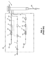
- FIG. 1 illustrates a conventional gas supply and exhaust system 25 and associated split/splitless injector 1 of the prior art.
- the split/splitless (SSL) injector 1 is provided for receiving injections of liquid samples from a syringe (not illustrated), for flash vaporizing the liquid samples by application of heat, for mixing the volatilized sample material with a carrier gas and for providing a portion of the volatilized sample material to a gas chromatograph column 20.
- the carrier gas supply e.g. helium
- a controlled pressure of the carrier gas is provided to the injector by an electronic pressure controller (not shown) which results in a controlled flow of carrier gas through column 20.
- a fine porosity filter 4 removes any particulate matter that may foul operation of a proportional valve 5 that is disposed downstream in the gas inlet line 7.
- the proportional valve 5 maintains a setpoint pressure within the body of the injector 1 in response to measurements provided by pressure sensor 8 in order to establish a calculated flow in the analytical column in accordance with the Poiseuille equation.
- the pressure sensor 8 provides a feedback loop to a control circuit of the electronic pressure controller.
- a chemical trap 6 is included in the gas inlet line 7 to scrub the carrier gas of potential contaminants, e.g. hydrocarbons and/or oxygen.
- a chemical trap 15 may be included in the split flow vent line 14 to protect the proportional valve 16 from contamination by various oils and greases that may volatilize from the sample or outgas from injector components.
- Another similar chemical trap (not shown) may also be included in the septum purge vent line 13.
- the injector 1 includes two basic modes of operation: split and splitless.
- split injection mode a split flow is established that exits the split vent line 14. This mode of operation is used for injection of concentrated analytes to prevent overloading of the column or saturation of the detection system used at the terminal end of the column.
- splitless mode of operation the split vent line 14 is closed (i.e., proportional valve 16 is closed) during a sample injection to cause the bulk of the sample material to be transferred to the capillary column. After a specified time interval, the split vent line is once again opened to vent residual solvent vapors and to dilute any contaminants that might outgas from contaminated surfaces.
- Helium which is a finite natural resource, is becoming increasingly expensive and difficult to procure in some areas of the world. Helium is often the preferred gas of choice due to sensitivity, efficiency, chemical inertness, safety or other concerns.
- Alternative carrier gasses e.g. hydrogen or nitrogen, can be used in some instances.
- hydrogen decreases sensitivity for electron ionization (EI) and can cause dehydrohalogenation reactions in the ion source while nitrogen can result in charge exchange reactions, and is known to be less efficient as a carrier gas.
- EI electron ionization
- an injector for a gas chromatograph/mass spectrometer may be configured to allow vacuum to be applied to the septum purge vent and split flow vent while simultaneously disabling the flow of carrier gas. This allows for conserving helium gas while the instrument is in a standby condition, without the risk of column oxidation.
- a roughing pump such as a rotary vane mechanical pump
- a high-vacuum pump such as a turbomolecular pump or an oil diffusion pump
- a small residual purge gas flow may be delivered to the injector inlet line or a helium gas flow may be delivered to the column inlet. This enables a high temperature low pressure bakeout of inlet components.
- An electronic controller can execute the operations of bakeout and/or standby in an automated fashion, ensuring the foreline pressure has dropped to a minimal value before the mechanical pump is disabled.
- the controller can restart the mechanical pump if the pressure rises to a predetermined threshold, or allow it to remain on if the cycling rate is excessive due to a leak in the system (e.g. an excessively cored septum).
- the disclosed apparatus allows shutting off the helium carrier gas to a chromatograph in order to reduce helium consumption during non-runtime, without risk of undue oxidation of the GC column. Additionally, overall system power consumption may also be reduced and the inlet can be efficiently cleaned by application of heat and vacuum.
- a gas chromatography (GC) system comprises: a sample injector adapted to receive a liquid sample into an interior cavity thereof and to volatilize the liquid sample; a GC column configured to receive the volatilized sample from the sample injector; a carrier gas inlet line fluidically coupled to a gas inlet port of the sample injector; a septum purge vent line fluidically coupled to a first gas outlet port of the sample injector; a split-flow vent line fluidically coupled to a second gas outlet port of the sample injector; and a vacuum system configured to apply vacuum to the septum purge vent line, the split-flow vent line and the interior cavity of the sample injector.
- a carrier gas inlet line fluidically coupled to a gas inlet port of the sample injector
- a septum purge vent line fluidically coupled to a first gas outlet port of the sample injector
- a split-flow vent line fluidically coupled to a second gas outlet port of the sample injector
- a vacuum system configured to apply vacuum to the septum purge vent
- a gas chromatography (GC) system comprises: a sample injector adapted to receive a liquid sample into an interior cavity thereof and to volatilize the liquid sample; a GC column configured to receive the volatilized sample from the sample injector; a carrier gas inlet line fluidically coupled to a gas inlet port of the sample injector; a septum purge vent line fluidically coupled to a first gas outlet port of the sample injector; a split-flow vent line fluidically coupled to a second gas outlet port of the sample injector; and a vacuum system fluidically coupled to a vacuum port of the sample injector.
- a sample injector adapted to receive a liquid sample into an interior cavity thereof and to volatilize the liquid sample
- a GC column configured to receive the volatilized sample from the sample injector
- a carrier gas inlet line fluidically coupled to a gas inlet port of the sample injector
- a septum purge vent line fluidically coupled to a first gas outlet port of the sample injector
- a method for operating a gas chromatography (GC) system comprising (a) a GC column within a heating oven and (b) a sample injector fluidically coupled to the GC column and having a carrier gas inlet port, a septum purge outlet port and a split-flow outlet port, wherein the method comprises: (i) discontinuing heating of the GC column by the heating oven; (ii) discontinuing the flow of a carrier gas into the carrier gas inlet port; and (iii) directing outputs of the septum purge outlet port and the split-flow vent outlet port to a vacuum system such that vacuum is applied to an interior cavity of the injector.
- a gas chromatography (GC) system comprising (a) a GC column within a heating oven and (b) a sample injector fluidically coupled to the GC column and having a carrier gas inlet port, a septum purge outlet port and a split-flow outlet port, wherein the method comprises: (i) discontinuing heating of the GC column by the heating oven
- the method may further comprise: (iv) providing helium gas so as to flow circumferentially around an exterior surface of the GC column in a direction generally towards an inlet of the GC column such that a portion of the helium gas enters the column inlet.
- a method for operating a gas chromatography (GC) system comprising (a) a GC column within a heating oven and (b) a sample injector fluidically coupled to the GC column and having a carrier gas inlet port, a septum purge outlet port, a split-flow outlet port and a vacuum port, wherein the method comprises: (i) discontinuing heating of the GC column by the heating oven; (ii) discontinuing a flow of a carrier gas into the carrier gas inlet port; closing the septum purge outlet port and the split-flow vent outlet port so as to prevent gas flow therethrough; and (iii) placing the vacuum port into fluidic communication with a vacuum system such that vacuum is applied to an interior cavity of the injector.
- a gas chromatography (GC) system comprising (a) a GC column within a heating oven and (b) a sample injector fluidically coupled to the GC column and having a carrier gas inlet port, a septum purge outlet port, a split-flow outlet port and a
- the method may further comprise: (iv) providing helium gas so as to flow circumferentially around an exterior surface of the GC column in a direction generally towards an inlet of the GC column such that a portion of the helium gas enters the column inlet.
- a method for operating a gas chromatography (GC) system comprising (a) a GC column within a heating oven and (b) a sample injector fluidically coupled to the GC column and having a carrier gas inlet port, a septum purge outlet port and a split-flow outlet port, wherein the method comprises: (i) discontinuing the flow of a carrier gas into the carrier gas inlet port; (ii) directing outputs of the septum purge outlet port and the split-flow vent outlet port to a vacuum system such that vacuum is applied to an interior cavity of the injector, wherein the heating oven is maintained at an above-ambient operating temperature; and (iii) providing helium gas so as to flow circumferentially around an exterior surface of the GC column in a direction generally towards an inlet of the GC column such that a portion of the helium gas enters the column inlet.
- the flow rate of the helium gas may be chosen so as to be sufficient to prevent degradation of the
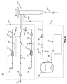
- FIG. 2 illustrates a first gas supply and exhaust system 30 for a gas chromatograph in accordance the present teachings.
- the system 30 shown in FIG. 2 may be fluidically coupled to a split/splitless injector apparatus 1 by means of gas inlet line 7, septum purge vent line 13 and split-flow vent line 14.
- gas inlet line 7 a split/splitless injector apparatus 1
- septum purge vent line 13 a split/splitless injector apparatus 1
- split-flow vent line 14 Various components that are numbered similarly in FIG. 1 and FIG. 2 have similar functions and, thus, the descriptions of such components are not repeated in detail here.
- the vent lines 13, 14 do not have separate exhaust ports, but are, instead, fluidically coupled by a tee-junction 32 which is also fluidically coupled to a common port of a three-port valve 31. Another port of the three-port valve 31 is fluidically coupled to an exhaust port 12. The remaining port of the three-port valve is fluidically coupled to a vent port or interstage port of a turbomolecular pump 35 by means of vacuum line 33.
- the foreline port of the vacuum pump 35 exhausts to foreline 36 which fluidically couples the vacuum pump 35 to a low-vacuum or "roughing" pump 37 such as a rotary vane mechanical pump.
- a pressure sensor (vacuum sensor) 38 may monitor the pressure of the vacuum line 33; a second such sensor 39 may monitor the pressure of the foreline 36.
- the three-port valve 31 is configured such that the flow from both the septum purge vent line 13 and the split-flow vent line 14 is directed to the single exhaust port 12.
- the three-port valve 31 may be configured such that the flow from both of the vent lines 13, 14 is directed into the vacuum line 33.
- the inlet line proportional valve 5 is closed, thus shutting off the flow of the carrier gas (typically helium). Under these conditions, all of the gas lines of the system 30 (other than the line connected to exhaust port 12) and the injector 1 itself are placed under vacuum.
- a flow restricting element 34 such as a frit, capillary or orifice may be added to line 33 in order to keep the critical foreline pressure of pump 35 from being exceeded.
- This novel configuration allows for conserving helium gas while the instrument is in a standby condition, without the risk of column oxidation. Additionally, since no gas load is applied, power can also be conserved by switching off the roughing pump 37 while the intermediate- or high-vacuum pump 35 remains active.
- a small residual purge gas flow may be delivered to the inlet line 7 of the system 30 by maintaining the proportional valve 5 in a slightly open condition.
- An electronic pressure controller 26 may monitor the pressure the subambient pressure of the system recorded by pressure sensor 8 and/or pressure sensor 38 and may control the residual purge flow rate at a predetermined value by operating the proportional valve 5 so as to maintain a target pressure. With the injector maintained at operating temperature, this enables a high temperature, low pressure bakeout of inlet and injector components.
- An electronic controller 27 that is electronically coupled to the vacuum sensors 38, 39 can execute the operations of bakeout and/or standby in an automated fashion, ensuring the foreline pressure has dropped to a minimal value before the mechanical pump is disabled. The controller can restart the mechanical pump if the pressure rises to a predetermined threshold, or allow it to remain on if the cycling rate is excessive due to a leak in the system (e.g. an excessively cored septum).
- FIG. 3 illustrates a second gas supply and exhaust system for a gas chromatograph in accordance with an embodiment of the present teachings.
- the system 40 shown in FIG. 3 comprises a gas supply and exhaust sub-system 41 that is only slightly modified from a conventional system (e.g., see FIG. 1 ) and also comprises a separate vacuum sub-system 42.
- the injector 101 of the system 40 is modified, in comparison to a conventional injector, in that it comprises an additional vacuum port 33p that fluidically couples the injector to a vacuum line 33 of the vacuum system 42.
- the vacuum sub-system 42 is not fluidically coupled to the gas supply and exhaust sub-system 41 other than possibly through the injector 101 as an intermediary component.
- the gas supply and exhaust sub-system 41 of the system 40 may comprise shutoff valves 43, 44 disposed in the septum purge vent line 13 and split-flow vent line 14, respectively, so as to prevent suction from being applied to these lines during times that the injector 101 is under vacuum.
- Another shutoff valve (not shown) may optionally be installed in the gas inlet line 7 if either the proportional valve 5 or the chemical trap 6 is not suitable for use with vacuum.
- the vacuum line 33 may also comprise another shutoff valve 45 to prevent vacuum from being applied to the injector 101 during injection periods or during column operation.
- a chemical trap 46 may be disposed in the vacuum line 33 so as to prevent back-diffusion of contaminants into the injector while it is under vacuum.
- an electronic pressure controller may monitor the pressure sensors and may operate the valves, accordingly, so as to maintain desired flow rates.
- a separate electronic controller may perform similar functions with regard to the vacuum sub-system.
- the shutoff valve 45 of the vacuum sub-system is closed and the shutoff valves 43, 44 of the gas supply and exhaust sub-system 41 are maintained open so that the septum purge vent line 13 and the split-flow vent line 14 perform their normal functions.
- the shutoff valves 43, 44 are closed.
- the proportional valve 5 (or other shutoff valve) may be closed so as to stop the flow of helium from inlet line 7 into the injector. Either simultaneously or just subsequently, the shutoff valve 45 is opened so as to place the injector under vacuum.
- a small residual purge gas flow may be delivered to the inlet line 7 of the system 30 while the injector is under vacuum by maintaining the proportional valve 5 in a slightly open condition. With the injector 101 maintained at operating temperature, application of vacuum to the injector in this fashion enables a high temperature, low pressure bakeout of inlet and injector components. It is understood that additional flow restricting elements may be placed in line 33 in order to keep the critical backing pressure of pump 35 from being exceeded when opening valve 45.
- Certain embodiments of the instant invention may employ techniques and apparatus components as described in U.S. Patent 8,371,152 titled "Helium Conservation Device for a Gas Chromatograph, said patent assigned to the assignee of the instant invention and incorporated herein by reference in its entirety.
- the aforementioned patent describes methods of purging a gas chromatograph system that include selecting between a first and a second mode.
- the first mode allows maximum helium conservation while the second mode allows minimum adverse effects on chromatographic methods, e.g. on retention times and detector responses.
- an injector inlet is supplied with an auxiliary gas that is non-helium and the pressure of the non-helium gas is set to correspond to a given column flow.
- a helium flow from a gas inlet is established around the end of the analytical capillary column, wherein the helium flow is less than the column flow.
- a helium flow is established around the end of the analytical capillary column, wherein the helium flow is greater than the column flow.
- the injector inlet when minimum method adverse effect is selected, the injector inlet is supplied with helium and the pressure of the helium gas is set to correspond to a given column flow.
- a helium flow from the second gas inlet is established around the inlet end of the analytical capillary column, wherein the coaxial helium flow is less than the column flow.
- a helium flow is established around the inlet end of the analytical column, wherein the helium flow is greater than the column flow.
- the main injector inlet is then supplied with a non-helium auxiliary gas.
- the auxiliary gas may be hydrogen, nitrogen, or argon.
- the helium gas flow that is established around the end of the analytical capillary column may be provided by a helium gas inlet line that is separate from the carrier gas inlet line and that is configured to supply helium gas so as to flow circumferentially around an exterior surface of the gas chromatography column in a direction generally towards an inlet of the gas chromatography column such that a portion of the helium gas enters the column inlet.
- the portion of the GC column having the exterior surface around which the helium circumferentially flows may be contained in a short length of pre-column tubing fluidically coupled between the injector and the GC column by a tee-coupling device.
- the pre-column tubing may comprise a few centimeter length of 0.53 mm inner diameter (ID) fused silica tubing, steel-clad fused silica tubing, glass lined stainless steel tubing, etc.
- ID inner diameter
- the portion of the GC column having the exterior surface around which the helium circumferentially flows may be contained in a short segment of fused silica tubing that extends into an interior cavity (e.g., a volatilization chamber) of the injector.
- the fused silica tubing may comprise a deactivated GC column tubing having an inner diameter (ID) that is sufficiently large to contain the active analytical GC column, leaving a space around the analytical column for gas to flow.
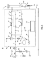
- FIG. 4 shows a third gas supply and exhaust system for a gas chromatograph in accordance with an embodiment of the present teachings.
- the system 50 illustrated in FIG. 4 includes a sub-system 30 that is identical to the system 30 shown in FIG. 2 . It should be noted that the system 50 could be modified by replacing the sub-system 30 by the sub-systems 41, 42 shown in FIG. 3 and by replacing the illustrated injector 1 by the modified injector 101.
- the system 50 further includes additional provisions, relative to the above-described embodiments, for supplying a non-helium auxiliary gas and for providing helium from a second inlet so as to establish a helium flow around the inlet end of an analytical column.
- a conventional injector 1 is modified by outfitting it with a short segment of pre-column 76 and low-dead-volume tee-coupling 78 both of which are disposed within a small heated zone 80.
- the temperature control of heated zone 80 can be provided by an external controller or by an unused auxiliary heater channel as is often found on typical GC systems.
- the pre-column 76 is preferably as short as possible and comprises a few centimeter length of 0.53 mm inner diameter (ID) fused silica tubing, steel-clad fused silica tubing, glass lined stainless steel tubing, etc.
- the inlet of analytical column 20 should preferably pass through the tee-coupling 78 and terminate within the heated pre-column 76, preferably within one centimeter of the end of the pre-column that is closest to the injector.
- a 3-way selection valve 84 such as a common solenoid valve, allows selection of one of an auxiliary gas from gas line 86 or helium gas from gas line 88.
- the valve 84 allows (optionally) selection between helium and an auxiliary gas during an injection period.
- the three-way valve 84 can alternatively comprise a pair of on/off valves if superior isolation between helium and the auxiliary gas is desired.
- An on/off type shutoff valve 90 receives a helium flow from gas line 88 via a flow restrictor 92 set to a flow that is above the analytical column flow, such as 2 sccm.
- the dimensions of the restrictor 92 and another restrictor 94 can be selected based on the input pressure of gas line 88 to establish a given flow range based on the pressure swing of injector 1.
- the actual flow can vary, e.g. 2-4 sccm without affecting performance.
- the second flow restrictor 94 is disposed in the flow path of conduit 96 for delivering a low purge flow for compensation of void volume effects.
- the flow delivered by the capillary restrictor 94 is less than the analytical column flow and can be, for purposes of illustration, 0.05 sccm.
- the shutoff valve 90 can be opened to deliver a flow of He that is greater than the column flow (e.g., 2 sccm flow) to the tee-coupling 78 during periods of run time. Otherwise, the valve 90 may be switched off during periods of injection, during cool down of the GC oven, or any non-run time period. Switching of the valve off during non-run time can reduce the helium consumption to nearly zero (0.05) for times when the instrumentation is not being used, utilizing instead the auxiliary gas for column flow. Activation of the valves 84, 90 can be accomplished using the time events programming features of most modern day gas chromatographs.
- the helium gas flow delivered by the conduit 96 to the tee-coupling 78 can be calculated using a mathematical model, or optimized empirically by adjusting the flow while monitoring the presence of auxiliary gas in the gas delivered to the column 20.
- the flow of helium into conduit 96 can be interrupted by closing the on/off valve 90 such that the delivered helium flow is reduced below the column flow.
- the auxiliary gas provided from gas line 86 will then sweep sample components onto the analytical column 20.
- the flow of He through conduit 96 is preferably reduced to a fraction of the column flow (rather than completely stopped) to a low value e.g.
- the helium flow in conduit 96 is re-established by opening valve 90 so that the chromatographic process utilizes helium within the column for the bulk of the analytical separation, while the auxiliary gas is used to purge the injector.
- FIG. 5 illustrates a portion of a fourth gas supply and exhaust system for a gas chromatograph in accordance with an embodiment of the present teachings.
- the system 60 a portion of which is shown in FIG. 5 , includes provisions for supplying a non-helium auxiliary gas and for providing helium from a second inlet so as to establish a helium flow around the inlet end of an analytical column.
- the lower portion of the SSL injector 201 is modified, relative to a conventional injector, so as to allow helium gas to be selectively passed over the end of an analytical column.
- the upper end of a conduit 138 e.g. short segment of deactivated fused silica tubing, is positioned within the confines of an injection port liner (not shown).
- the analytical column 20 Positioned within the tubing 138 is the analytical column 20 as is shown in the enlargement in inset 113.
- the short segment of fused silica tubing 138 is selected to have an internal diameter slightly larger than the outer diameter of the analytical column 20. For example, Megabore tubing of 0.53 mm ID is suitable for most analytical columns with internal diameters of 0.25 or 0.32 mm ID.
- the tubing 138 has been deactivated and contains no stationary phase.
- This segment of tubing alternatively can be fabricated from glass lined stainless steel tubing, SilcosteelTM tubing, or other suitably inert material.
- the analytical column 20 extends preferably to within 1 cm of the uppermost end of the tubing 138. This positioning allows locating the column entrance within the hot injector body, minimizes void volume effects and allows a sufficient back diffusion barrier to the auxiliary gas during analysis.
- a liner support 142 and base 144 of the injector 201 are screwed together at the threaded stem 146 to allow compression of an encapsulated graphite ferrule 148. This configuration maintains a gas tight seal between the fused silica tubing 138 and the base 144.
- a soft metallic gasket 150 is positioned between the base 144 and terminal end 110A of the injector body 110 to create a seal between base 144 and the injector body 110.
- a retaining nut (not shown) secures the base 144 to the threaded portion 152 of injector body 110.
- the gasket 150 of the injector 201 of the system 60 includes a pair of gas channels 154a, 154b in the form of annular grooves cut on each face of the metallic gasket 150.
- the gasket 150 shown in top view in inset 111 also includes a hole 156 located on the centerline of gasket 150 to create a fluid communication between the upper and lower groove channels 154a, 154b.
- the terminal end 158 of base 144 is threaded so that a retaining nut and ferrule (not shown for simplicity) can create a seal between the analytical column 20 and the base 144.
- a conduit 160 fluidically coupled to gas line 96 supplies a flow of helium to the upper groove channel 154a.
- the helium flows around the upper groove channel until it finds hole 156. It then passes through hole 156 into the lower groove channel 154b and into base 144 at entrance point 155.
- the base 144 allows the helium to flow downward around the outside of the fused silica tube 138 to sweep void volume then proceed upward into tube 138 and finally injector the injector interior after passing the input end of the analytical column 20.
- the flow established into the conduit 160 should be slightly higher than the calculated column flow delivered to column 20 following the injection period.
- 2 sccm of conduit flow could be used for calculated column flows of 1 sccm.
- the conduit 160 may comprise a 304 stainless steel tube of 0.9 mm outer diameter (OD), 0.5 mm ID and 300 mm length. The conduit is attached to the hot injector body 110.
- FIGS. 2-3 By combining an injector inlet evacuation system (e.g., FIGS. 2-3 ) with the ability to provide an auxiliary non-helium purge and split flow as well as a separate helium flow surrounding the column entrance (e.g., FIGS. 4-5 ), flexibility in gas conservation is achieved.
- a user may use the helium conservation techniques described in the aforementioned U.S. Patent 8,371,152 during sample injections and between injections when samples are being analyzed in order to conserve helium carrier gas. Additionally, a user may employ the injector evacuation techniques taught herein when the gas chromatograph is placed into standby or idle mode, thereby conserving all gases.
- the injector evacuation techniques may be employed in conjunction with the technique of providing of a low flow of helium gas around and into the column entrance from a separate inlet. Providing a protective flow of helium gas in such a fashion can enable the column to remain hot during idle periods, while the injector interior is under partial vacuum, without incurring column degradation. It may be desirable to maintain the gas chromatograph column at its normal operating temperature if the column is one of a set of columns whose separate eluates are directed to a single detector such as, for example two separate columns coupled to a single ionization source of a mass spectrometer. Such a system may permit alternating analyses of samples provided from each column. In such a system, one column may be placed in standby mode for an extended period of time while a second column is supplying material to be analyzed by the detector.
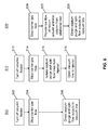
- FIG. 6 provides, in flow diagram form, a comparison of three exemplary methods for operating a gas chromatograph in accordance with the present teachings.
- Method 300 may be employed, for example, in conjunction with the system 30 of FIG. 2 or a similar system.
- the column heater typically an oven within which the column is disposed
- the flow of carrier gas typically helium
- This step may be accomplished, for example, by closing a valve, such as proportional valve 5 in FIG. 2 , that controls flow of the carrier gas into an inlet line.
- step 306 the output flows of the septum purge and split-flow lines are directed to a vacuum line so as to evacuate these lines as well as the injector.
- This step may be performed, for example, by reconfiguring the three-port valve (e.g., three-port valve 31) so that flow through both of the lines 13 and 14 is directed into the vacuum line 33.
- This set of steps may be used to place a gas chromatograph system into standby or idle mode.
- the sequence of steps may be reversed, with each such step in the reverse procedure performing an opposite function to that shown in FIG. 6 (e.g., instead of turning off the column heater as illustrated in the diagram, turn on the column heater in the reversed procedure).
- Method 310 is similar to step 300 (steps 312 and 314 of method 310 are identical to steps 302 and 304, respectively, of the method 300) and may be employed in conjunction with system 30 of FIG. 3 or a similar system that comprises a separate vacuum sub-system having a dedicated vacuum line to an injector.
- the septum purge vent line and split-flow vent lines are isolated from the injector (that is, removed from being in fluidic communication with the injector interior) by, for example, closing shutoff valves 43 and 44 in FIG. 3 .
- step 316 the injector is exposed to vacuum by, for example, opening a valve (e.g., shutoff valve 45) on a vacuum line (e.g., line 33) that leads to a dedicated port (e.g., port 33p) of the injector inlet.
- a valve e.g., shutoff valve 45
- a vacuum line e.g., line 33
- a dedicated port e.g., port 33p
- Method 320 is applicable, for example, to a system, such as system 40 illustrated in FIG. 4 that combines an evacuable injector inlet with in conjunction with a provision for supplying a low flow of helium gas around and into the column entrance from a separate inlet.
- the chromatographic column is allowed to remain at its operating temperature during practice of the method 320.
- the flow of purge gas either helium or an auxiliary gas such as nitrogen or argon
- step 325 a low flow of protective helium is provided (if not flowing already) around the column from an additional gas inlet so as to flow into the column.
- step 326 the output flows of the septum purge and split-flow lines are directed to a vacuum line so as to evacuate these lines as well as the injector.
- the low flow rate of helium into the column prevents degradation of the column at high temperature but does not significantly degrade the vacuum within the injector interior.
Landscapes
- Physics & Mathematics (AREA)
- Health & Medical Sciences (AREA)
- Life Sciences & Earth Sciences (AREA)
- Chemical & Material Sciences (AREA)
- Analytical Chemistry (AREA)
- Biochemistry (AREA)
- General Health & Medical Sciences (AREA)
- General Physics & Mathematics (AREA)
- Immunology (AREA)
- Pathology (AREA)
- Other Investigation Or Analysis Of Materials By Electrical Means (AREA)
- Sampling And Sample Adjustment (AREA)
Abstract
Description
- This invention relates to gas chromatography and, more particularly, to conservation of gases used as carrier gases in gas chromatograph injectors and columns.
- Traditional split/splitless (SSL) or programmed temperature vaporizing (PTV) injection ports for gas chromatographs typically consume large volumes of carrier gas by virtue of what is used at the split vent and septum purge vent rather than what is utilized for the actual analytical separation (column flow). To illustrate, a capillary column flow of approximately 1 standard cubic centimeter per minute (sccm) may have 50 sccm or more of split flow and 5 sccm of septum purge flow. One prior art method to reduce this consumption, e.g., "gas saver", can reduce the split flow following an injection period. Reducing the split flow to too low a value, however, can result in undesirable elevated baselines. This may be caused by a continual outgassing of higher molecular weight contaminants introduced from the sample matrix, outgassing of polymeric seals such as O-rings, injection port septa and/or coring of such septa, or be caused by oxidation of the column stationary phase due to larger concentrations of oxygen which has back-diffused through the septum. Reducing these contaminants has traditionally been accomplished through dilution by using large split flows. Thus, significant quantities of carrier gas may be consumed, even during chromatograph idle periods.
-
FIG. 1 illustrates a conventional gas supply andexhaust system 25 and associated split/splitless injector 1 of the prior art. The split/splitless (SSL) injector 1 is provided for receiving injections of liquid samples from a syringe (not illustrated), for flash vaporizing the liquid samples by application of heat, for mixing the volatilized sample material with a carrier gas and for providing a portion of the volatilized sample material to agas chromatograph column 20. The carrier gas supply, e.g. helium, is introduced under pressure into agas inlet line 7 by means of agas fitting 3. A controlled pressure of the carrier gas is provided to the injector by an electronic pressure controller (not shown) which results in a controlled flow of carrier gas throughcolumn 20. Afine porosity filter 4, e.g. a stainless steel frit, removes any particulate matter that may foul operation of aproportional valve 5 that is disposed downstream in thegas inlet line 7. Theproportional valve 5 maintains a setpoint pressure within the body of the injector 1 in response to measurements provided bypressure sensor 8 in order to establish a calculated flow in the analytical column in accordance with the Poiseuille equation. Thepressure sensor 8 provides a feedback loop to a control circuit of the electronic pressure controller. Optionally, achemical trap 6 is included in thegas inlet line 7 to scrub the carrier gas of potential contaminants, e.g. hydrocarbons and/or oxygen. - As is known, generally only a portion (and, frequently, only a small portion) of the volatilized sample material and carrier gas flow actually enters the
column 20. The remainder of the volatilized sample material and carrier gas flow is exhausted from the system by means of septumpurge vent line 13 and, frequently, splitflow vent line 14.Flow restrictor 11 andflow restrictor 18, disposed, respectively, in the septumpurge vent line 13 and splitflow vent line 14 maintain a pressure difference between theexhaust ports vent lines Pressure sensors vent lines flow restrictors proportional valves vent lines chemical trap 15 may be included in the splitflow vent line 14 to protect theproportional valve 16 from contamination by various oils and greases that may volatilize from the sample or outgas from injector components. Another similar chemical trap (not shown) may also be included in the septumpurge vent line 13. - The injector 1 includes two basic modes of operation: split and splitless. In the split injection mode, a split flow is established that exits the
split vent line 14. This mode of operation is used for injection of concentrated analytes to prevent overloading of the column or saturation of the detection system used at the terminal end of the column. In the splitless mode of operation, thesplit vent line 14 is closed (i.e.,proportional valve 16 is closed) during a sample injection to cause the bulk of the sample material to be transferred to the capillary column. After a specified time interval, the split vent line is once again opened to vent residual solvent vapors and to dilute any contaminants that might outgas from contaminated surfaces. - In both the split and splitless modes, far greater amounts of carrier gas are used for split flow and septum purge flow than are required for the gas chromatography (GC) column flow carrying out the analytical separation. During idle times following a split or splitless injection, large volumes of split flow are typically maintained to dilute outgassing of residual contaminants. Even during idle times, when the chromatography system is not in use and the column is cooled to room temperature, the injector remains at above-ambient temperature and under a continued flow of gas. This results in a large consumption of high purity gas, e.g. helium.
- Helium, which is a finite natural resource, is becoming increasingly expensive and difficult to procure in some areas of the world. Helium is often the preferred gas of choice due to sensitivity, efficiency, chemical inertness, safety or other concerns. Alternative carrier gasses, e.g. hydrogen or nitrogen, can be used in some instances. For a mass spectrometer detection based system, hydrogen decreases sensitivity for electron ionization (EI) and can cause dehydrohalogenation reactions in the ion source while nitrogen can result in charge exchange reactions, and is known to be less efficient as a carrier gas. Thus, there is a need in the art for gas chromatography systems that conserve helium by restricting the times at which helium gas flow is applied to only those times when such helium flow is required and by restricting the flow rate of helium at such times to be not significantly greater than the minimum flow rate required.
- The inventor of the present invention has realized that many of the beneficial aspects associated with the flow of helium and other carrier gases through a chromatography injector can be achieved, during injector idle or standby times, by simply discontinuing the flow of carrier gas and, instead, applying vacuum to the injector. Accordingly, an injector (or injection port) for a gas chromatograph/mass spectrometer may be configured to allow vacuum to be applied to the septum purge vent and split flow vent while simultaneously disabling the flow of carrier gas. This allows for conserving helium gas while the instrument is in a standby condition, without the risk of column oxidation. Additionally, since no gas load is applied, power can also be conserved by switching off a roughing pump (such as a rotary vane mechanical pump) while a high-vacuum pump (such as a turbomolecular pump or an oil diffusion pump) remains active. In some embodiments, a small residual purge gas flow may be delivered to the injector inlet line or a helium gas flow may be delivered to the column inlet. This enables a high temperature low pressure bakeout of inlet components. An electronic controller can execute the operations of bakeout and/or standby in an automated fashion, ensuring the foreline pressure has dropped to a minimal value before the mechanical pump is disabled. The controller can restart the mechanical pump if the pressure rises to a predetermined threshold, or allow it to remain on if the cycling rate is excessive due to a leak in the system (e.g. an excessively cored septum). The disclosed apparatus allows shutting off the helium carrier gas to a chromatograph in order to reduce helium consumption during non-runtime, without risk of undue oxidation of the GC column. Additionally, overall system power consumption may also be reduced and the inlet can be efficiently cleaned by application of heat and vacuum.
- Accordingly, in a first aspect of the present teachings, a gas chromatography (GC) system comprises: a sample injector adapted to receive a liquid sample into an interior cavity thereof and to volatilize the liquid sample; a GC column configured to receive the volatilized sample from the sample injector; a carrier gas inlet line fluidically coupled to a gas inlet port of the sample injector; a septum purge vent line fluidically coupled to a first gas outlet port of the sample injector; a split-flow vent line fluidically coupled to a second gas outlet port of the sample injector; and a vacuum system configured to apply vacuum to the septum purge vent line, the split-flow vent line and the interior cavity of the sample injector.
- According to a second aspect of the present teachings, a gas chromatography (GC) system comprises: a sample injector adapted to receive a liquid sample into an interior cavity thereof and to volatilize the liquid sample; a GC column configured to receive the volatilized sample from the sample injector; a carrier gas inlet line fluidically coupled to a gas inlet port of the sample injector; a septum purge vent line fluidically coupled to a first gas outlet port of the sample injector; a split-flow vent line fluidically coupled to a second gas outlet port of the sample injector; and a vacuum system fluidically coupled to a vacuum port of the sample injector.
- According to a third aspect of the present teachings, there is provided a method for operating a gas chromatography (GC) system comprising (a) a GC column within a heating oven and (b) a sample injector fluidically coupled to the GC column and having a carrier gas inlet port, a septum purge outlet port and a split-flow outlet port, wherein the method comprises: (i) discontinuing heating of the GC column by the heating oven; (ii) discontinuing the flow of a carrier gas into the carrier gas inlet port; and (iii) directing outputs of the septum purge outlet port and the split-flow vent outlet port to a vacuum system such that vacuum is applied to an interior cavity of the injector. The method may further comprise: (iv) providing helium gas so as to flow circumferentially around an exterior surface of the GC column in a direction generally towards an inlet of the GC column such that a portion of the helium gas enters the column inlet.
- According to another aspect of the present teachings, there is provided a method for operating a gas chromatography (GC) system comprising (a) a GC column within a heating oven and (b) a sample injector fluidically coupled to the GC column and having a carrier gas inlet port, a septum purge outlet port, a split-flow outlet port and a vacuum port, wherein the method comprises: (i) discontinuing heating of the GC column by the heating oven; (ii) discontinuing a flow of a carrier gas into the carrier gas inlet port; closing the septum purge outlet port and the split-flow vent outlet port so as to prevent gas flow therethrough; and (iii) placing the vacuum port into fluidic communication with a vacuum system such that vacuum is applied to an interior cavity of the injector. The method may further comprise: (iv) providing helium gas so as to flow circumferentially around an exterior surface of the GC column in a direction generally towards an inlet of the GC column such that a portion of the helium gas enters the column inlet.
- According to yet another aspect of the present teachings, there is provided a method for operating a gas chromatography (GC) system comprising (a) a GC column within a heating oven and (b) a sample injector fluidically coupled to the GC column and having a carrier gas inlet port, a septum purge outlet port and a split-flow outlet port, wherein the method comprises: (i) discontinuing the flow of a carrier gas into the carrier gas inlet port; (ii) directing outputs of the septum purge outlet port and the split-flow vent outlet port to a vacuum system such that vacuum is applied to an interior cavity of the injector, wherein the heating oven is maintained at an above-ambient operating temperature; and (iii) providing helium gas so as to flow circumferentially around an exterior surface of the GC column in a direction generally towards an inlet of the GC column such that a portion of the helium gas enters the column inlet. The flow rate of the helium gas may be chosen so as to be sufficient to prevent degradation of the GC column at the operating temperature but insufficient to prevent maintenance of vacuum within an interior cavity of the sample injector.
-
-
FIG. 1 shows a conventional gas supply and exhaust system and Split/Splitless injector for a gas chromatograph. -
FIG. 2 illustrates a first gas supply and exhaust system for a gas chromatograph in accordance with an embodiment of the present teachings. -
FIG. 3 illustrates a second gas supply and exhaust system for a gas chromatograph in accordance with an embodiment of the present teachings. -
FIG. 4 illustrates a third gas supply and exhaust system for a gas chromatograph in accordance with an embodiment of the present teachings. -
FIG. 5 illustrates a portion of a fourth gas supply and exhaust system for a gas chromatograph in accordance with an embodiment of the present teachings, wherein the system includes a Split/Splitless injector that uses a short narrow bore tube assembly. -
FIG. 6 is a set of flow diagrams of three exemplary methods in accordance with the present teachings. - This disclosure describes improved gas chromatograph injector systems and methods for operating gas chromatograph injectors. The following description is presented to enable any person skilled in the art to make and use the invention, and is provided in the context of a particular application and its requirements. Various modifications to the described embodiments will be readily apparent to those skilled in the art and the generic principles herein may be applied to other embodiments. Thus, the present invention is not intended to be limited to the embodiments and examples shown but is to be accorded the widest possible scope in accordance with the features and principles shown and described. To more particularly appreciate the features of the present invention, the reader is referred to
FIGS. 2 through 6 in conjunction with the following description. -
FIG. 2 illustrates a first gas supply andexhaust system 30 for a gas chromatograph in accordance the present teachings. Similarly to the conventional gas supply andexhaust system 25 illustrated inFIG. 1 , thesystem 30 shown inFIG. 2 may be fluidically coupled to a split/splitless injector apparatus 1 by means ofgas inlet line 7, septumpurge vent line 13 and split-flow vent line 14. Various components that are numbered similarly inFIG. 1 andFIG. 2 have similar functions and, thus, the descriptions of such components are not repeated in detail here. - In contrast to the gas supply and
exhaust system 25 illustrated inFIG. 1 , thesystem 30 shown inFIG. 2 , the vent lines 13, 14 do not have separate exhaust ports, but are, instead, fluidically coupled by a tee-junction 32 which is also fluidically coupled to a common port of a three-port valve 31. Another port of the three-port valve 31 is fluidically coupled to anexhaust port 12. The remaining port of the three-port valve is fluidically coupled to a vent port or interstage port of aturbomolecular pump 35 by means ofvacuum line 33. The foreline port of thevacuum pump 35 exhausts to foreline 36 which fluidically couples thevacuum pump 35 to a low-vacuum or "roughing"pump 37 such as a rotary vane mechanical pump. A pressure sensor (vacuum sensor) 38 may monitor the pressure of thevacuum line 33; a secondsuch sensor 39 may monitor the pressure of theforeline 36. - During normal operation of the injector, the three-
port valve 31 is configured such that the flow from both the septumpurge vent line 13 and the split-flow vent line 14 is directed to thesingle exhaust port 12. However, during system standby, after the gas chromatography column has been cooled, the three-port valve 31 may be configured such that the flow from both of the vent lines 13, 14 is directed into thevacuum line 33. At the same time as or just prior to the time that the three-port valve 31 is configured to send the venting gases to the vacuum line, the inlet lineproportional valve 5 is closed, thus shutting off the flow of the carrier gas (typically helium). Under these conditions, all of the gas lines of the system 30 (other than the line connected to exhaust port 12) and the injector 1 itself are placed under vacuum. Aflow restricting element 34 such as a frit, capillary or orifice may be added toline 33 in order to keep the critical foreline pressure ofpump 35 from being exceeded. This novel configuration allows for conserving helium gas while the instrument is in a standby condition, without the risk of column oxidation. Additionally, since no gas load is applied, power can also be conserved by switching off theroughing pump 37 while the intermediate- or high-vacuum pump 35 remains active. - In some embodiments, a small residual purge gas flow may be delivered to the
inlet line 7 of thesystem 30 by maintaining theproportional valve 5 in a slightly open condition. Anelectronic pressure controller 26 may monitor the pressure the subambient pressure of the system recorded bypressure sensor 8 and/orpressure sensor 38 and may control the residual purge flow rate at a predetermined value by operating theproportional valve 5 so as to maintain a target pressure. With the injector maintained at operating temperature, this enables a high temperature, low pressure bakeout of inlet and injector components. Anelectronic controller 27 that is electronically coupled to thevacuum sensors -
FIG. 3 illustrates a second gas supply and exhaust system for a gas chromatograph in accordance with an embodiment of the present teachings. Thesystem 40 shown inFIG. 3 comprises a gas supply andexhaust sub-system 41 that is only slightly modified from a conventional system (e.g., seeFIG. 1 ) and also comprises aseparate vacuum sub-system 42. Theinjector 101 of thesystem 40 is modified, in comparison to a conventional injector, in that it comprises anadditional vacuum port 33p that fluidically couples the injector to avacuum line 33 of thevacuum system 42. Thus, thevacuum sub-system 42 is not fluidically coupled to the gas supply andexhaust sub-system 41 other than possibly through theinjector 101 as an intermediary component. - The gas supply and
exhaust sub-system 41 of the system 40 (FIG. 3 ) may compriseshutoff valves purge vent line 13 and split-flow vent line 14, respectively, so as to prevent suction from being applied to these lines during times that theinjector 101 is under vacuum. Another shutoff valve (not shown) may optionally be installed in thegas inlet line 7 if either theproportional valve 5 or thechemical trap 6 is not suitable for use with vacuum. Likewise, thevacuum line 33 may also comprise anothershutoff valve 45 to prevent vacuum from being applied to theinjector 101 during injection periods or during column operation. Achemical trap 46 may be disposed in thevacuum line 33 so as to prevent back-diffusion of contaminants into the injector while it is under vacuum. - Other components of the
system 40 have functions which are similar to the similarly numbered components shown inFIGS. 1-2 and the discussion of such components is not repeated here. As already discussed with reference toFIG. 2 , an electronic pressure controller (not specifically shown) may monitor the pressure sensors and may operate the valves, accordingly, so as to maintain desired flow rates. A separate electronic controller (not shown) may perform similar functions with regard to the vacuum sub-system. - During normal operation of the injector 101 (
FIG. 3 ), theshutoff valve 45 of the vacuum sub-system is closed and theshutoff valves exhaust sub-system 41 are maintained open so that the septumpurge vent line 13 and the split-flow vent line 14 perform their normal functions. However, during system standby, after the gas chromatography column has been cooled, theshutoff valves inlet line 7 into the injector. Either simultaneously or just subsequently, theshutoff valve 45 is opened so as to place the injector under vacuum. In some embodiments, a small residual purge gas flow may be delivered to theinlet line 7 of thesystem 30 while the injector is under vacuum by maintaining theproportional valve 5 in a slightly open condition. With theinjector 101 maintained at operating temperature, application of vacuum to the injector in this fashion enables a high temperature, low pressure bakeout of inlet and injector components. It is understood that additional flow restricting elements may be placed inline 33 in order to keep the critical backing pressure ofpump 35 from being exceeded when openingvalve 45. - Certain embodiments of the instant invention may employ techniques and apparatus components as described in
U.S. Patent 8,371,152 titled "Helium Conservation Device for a Gas Chromatograph, said patent assigned to the assignee of the instant invention and incorporated herein by reference in its entirety. In brief, the aforementioned patent describes methods of purging a gas chromatograph system that include selecting between a first and a second mode. The first mode allows maximum helium conservation while the second mode allows minimum adverse effects on chromatographic methods, e.g. on retention times and detector responses. - According to the aforementioned U.S. patent, when maximum helium conservation is selected, an injector inlet is supplied with an auxiliary gas that is non-helium and the pressure of the non-helium gas is set to correspond to a given column flow. During an injection period, a helium flow from a gas inlet is established around the end of the analytical capillary column, wherein the helium flow is less than the column flow. Following the injection period, a helium flow is established around the end of the analytical capillary column, wherein the helium flow is greater than the column flow.
- According to the aforementioned U.S. patent, when minimum method adverse effect is selected, the injector inlet is supplied with helium and the pressure of the helium gas is set to correspond to a given column flow. During an injection period, a helium flow from the second gas inlet is established around the inlet end of the analytical capillary column, wherein the coaxial helium flow is less than the column flow. Following the injection period, a helium flow is established around the inlet end of the analytical column, wherein the helium flow is greater than the column flow. The main injector inlet is then supplied with a non-helium auxiliary gas. The auxiliary gas may be hydrogen, nitrogen, or argon.
- As described below, the helium gas flow that is established around the end of the analytical capillary column may be provided by a helium gas inlet line that is separate from the carrier gas inlet line and that is configured to supply helium gas so as to flow circumferentially around an exterior surface of the gas chromatography column in a direction generally towards an inlet of the gas chromatography column such that a portion of the helium gas enters the column inlet. The portion of the GC column having the exterior surface around which the helium circumferentially flows may be contained in a short length of pre-column tubing fluidically coupled between the injector and the GC column by a tee-coupling device. The pre-column tubing may comprise a few centimeter length of 0.53 mm inner diameter (ID) fused silica tubing, steel-clad fused silica tubing, glass lined stainless steel tubing, etc. Alternatively, the portion of the GC column having the exterior surface around which the helium circumferentially flows may be contained in a short segment of fused silica tubing that extends into an interior cavity (e.g., a volatilization chamber) of the injector. The fused silica tubing may comprise a deactivated GC column tubing having an inner diameter (ID) that is sufficiently large to contain the active analytical GC column, leaving a space around the analytical column for gas to flow.
-
FIG. 4 shows a third gas supply and exhaust system for a gas chromatograph in accordance with an embodiment of the present teachings. Thesystem 50 illustrated inFIG. 4 includes a sub-system 30 that is identical to thesystem 30 shown inFIG. 2 . It should be noted that thesystem 50 could be modified by replacing thesub-system 30 by thesub-systems FIG. 3 and by replacing the illustrated injector 1 by the modifiedinjector 101. Thesystem 50 further includes additional provisions, relative to the above-described embodiments, for supplying a non-helium auxiliary gas and for providing helium from a second inlet so as to establish a helium flow around the inlet end of an analytical column. - In the system 50 (
FIG. 4 ), a conventional injector 1 is modified by outfitting it with a short segment ofpre-column 76 and low-dead-volume tee-coupling 78 both of which are disposed within a smallheated zone 80. The temperature control ofheated zone 80 can be provided by an external controller or by an unused auxiliary heater channel as is often found on typical GC systems. Thepre-column 76 is preferably as short as possible and comprises a few centimeter length of 0.53 mm inner diameter (ID) fused silica tubing, steel-clad fused silica tubing, glass lined stainless steel tubing, etc. The inlet ofanalytical column 20 should preferably pass through the tee-coupling 78 and terminate within theheated pre-column 76, preferably within one centimeter of the end of the pre-column that is closest to the injector. A 3-way selection valve 84, such as a common solenoid valve, allows selection of one of an auxiliary gas fromgas line 86 or helium gas fromgas line 88. Thevalve 84 allows (optionally) selection between helium and an auxiliary gas during an injection period. The three-way valve 84 can alternatively comprise a pair of on/off valves if superior isolation between helium and the auxiliary gas is desired. - An on/off
type shutoff valve 90, receives a helium flow fromgas line 88 via aflow restrictor 92 set to a flow that is above the analytical column flow, such as 2 sccm. The dimensions of the restrictor 92 and another restrictor 94 can be selected based on the input pressure ofgas line 88 to establish a given flow range based on the pressure swing of injector 1. The actual flow can vary, e.g. 2-4 sccm without affecting performance. Thesecond flow restrictor 94 is disposed in the flow path ofconduit 96 for delivering a low purge flow for compensation of void volume effects. The flow delivered by thecapillary restrictor 94 is less than the analytical column flow and can be, for purposes of illustration, 0.05 sccm. - The
shutoff valve 90 can be opened to deliver a flow of He that is greater than the column flow (e.g., 2 sccm flow) to the tee-coupling 78 during periods of run time. Otherwise, thevalve 90 may be switched off during periods of injection, during cool down of the GC oven, or any non-run time period. Switching of the valve off during non-run time can reduce the helium consumption to nearly zero (0.05) for times when the instrumentation is not being used, utilizing instead the auxiliary gas for column flow. Activation of thevalves - The helium gas flow delivered by the
conduit 96 to the tee-coupling 78 can be calculated using a mathematical model, or optimized empirically by adjusting the flow while monitoring the presence of auxiliary gas in the gas delivered to thecolumn 20. During injection of a sample into the injector 1 ofFIG. 4 , the flow of helium intoconduit 96 can be interrupted by closing the on/offvalve 90 such that the delivered helium flow is reduced below the column flow. The auxiliary gas provided fromgas line 86 will then sweep sample components onto theanalytical column 20. During injection, the flow of He throughconduit 96 is preferably reduced to a fraction of the column flow (rather than completely stopped) to a low value e.g. 0.05 sccm to help sweep void volumes, reduce peak tailing and prevent back diffusion of solvent vapors into the gas lines. Following the injection of the sample and sample transfer to theanalytical column 20, the helium flow inconduit 96 is re-established by openingvalve 90 so that the chromatographic process utilizes helium within the column for the bulk of the analytical separation, while the auxiliary gas is used to purge the injector. -
FIG. 5 illustrates a portion of a fourth gas supply and exhaust system for a gas chromatograph in accordance with an embodiment of the present teachings. Similarly to thesystem 50 illustrated inFIG. 4 , thesystem 60, a portion of which is shown inFIG. 5 , includes provisions for supplying a non-helium auxiliary gas and for providing helium from a second inlet so as to establish a helium flow around the inlet end of an analytical column. - In the
system 60, the lower portion of theSSL injector 201 is modified, relative to a conventional injector, so as to allow helium gas to be selectively passed over the end of an analytical column. The upper end of aconduit 138, e.g. short segment of deactivated fused silica tubing, is positioned within the confines of an injection port liner (not shown). Positioned within thetubing 138 is theanalytical column 20 as is shown in the enlargement ininset 113. The short segment of fusedsilica tubing 138 is selected to have an internal diameter slightly larger than the outer diameter of theanalytical column 20. For example, Megabore tubing of 0.53 mm ID is suitable for most analytical columns with internal diameters of 0.25 or 0.32 mm ID. Preferably, thetubing 138 has been deactivated and contains no stationary phase. This segment of tubing alternatively can be fabricated from glass lined stainless steel tubing, Silcosteel™ tubing, or other suitably inert material. In this illustrative example, theanalytical column 20 extends preferably to within 1 cm of the uppermost end of thetubing 138. This positioning allows locating the column entrance within the hot injector body, minimizes void volume effects and allows a sufficient back diffusion barrier to the auxiliary gas during analysis. - A
liner support 142 andbase 144 of theinjector 201 are screwed together at the threadedstem 146 to allow compression of an encapsulatedgraphite ferrule 148. This configuration maintains a gas tight seal between the fusedsilica tubing 138 and thebase 144. A softmetallic gasket 150 is positioned between the base 144 andterminal end 110A of theinjector body 110 to create a seal betweenbase 144 and theinjector body 110. A retaining nut (not shown) secures the base 144 to the threadedportion 152 ofinjector body 110. - The
gasket 150 of theinjector 201 of the system 60 (FIG. 5 ) includes a pair ofgas channels metallic gasket 150. Thegasket 150 shown in top view ininset 111 also includes ahole 156 located on the centerline ofgasket 150 to create a fluid communication between the upper andlower groove channels terminal end 158 ofbase 144 is threaded so that a retaining nut and ferrule (not shown for simplicity) can create a seal between theanalytical column 20 and thebase 144. Aconduit 160 fluidically coupled togas line 96 supplies a flow of helium to theupper groove channel 154a. The helium flows around the upper groove channel until it findshole 156. It then passes throughhole 156 into thelower groove channel 154b and intobase 144 atentrance point 155. Thebase 144 allows the helium to flow downward around the outside of the fusedsilica tube 138 to sweep void volume then proceed upward intotube 138 and finally injector the injector interior after passing the input end of theanalytical column 20. After sample injection, the flow established into theconduit 160 should be slightly higher than the calculated column flow delivered tocolumn 20 following the injection period. To illustrate, 2 sccm of conduit flow could be used for calculated column flows of 1 sccm. In this illustrative example (FIG. 5 ), theconduit 160 may comprise a 304 stainless steel tube of 0.9 mm outer diameter (OD), 0.5 mm ID and 300 mm length. The conduit is attached to thehot injector body 110. - By combining an injector inlet evacuation system (e.g.,
FIGS. 2-3 ) with the ability to provide an auxiliary non-helium purge and split flow as well as a separate helium flow surrounding the column entrance (e.g.,FIGS. 4-5 ), flexibility in gas conservation is achieved. A user may use the helium conservation techniques described in the aforementionedU.S. Patent 8,371,152 during sample injections and between injections when samples are being analyzed in order to conserve helium carrier gas. Additionally, a user may employ the injector evacuation techniques taught herein when the gas chromatograph is placed into standby or idle mode, thereby conserving all gases. - Additionally, if it is desired to maintain the gas chromatograph column at its normal operating temperature during a standby period, then the injector evacuation techniques may be employed in conjunction with the technique of providing of a low flow of helium gas around and into the column entrance from a separate inlet. Providing a protective flow of helium gas in such a fashion can enable the column to remain hot during idle periods, while the injector interior is under partial vacuum, without incurring column degradation. It may be desirable to maintain the gas chromatograph column at its normal operating temperature if the column is one of a set of columns whose separate eluates are directed to a single detector such as, for example two separate columns coupled to a single ionization source of a mass spectrometer. Such a system may permit alternating analyses of samples provided from each column. In such a system, one column may be placed in standby mode for an extended period of time while a second column is supplying material to be analyzed by the detector.
-
FIG. 6 provides, in flow diagram form, a comparison of three exemplary methods for operating a gas chromatograph in accordance with the present teachings.Method 300 may be employed, for example, in conjunction with thesystem 30 ofFIG. 2 or a similar system. Instep 302, the column heater (typically an oven within which the column is disposed) is turned off and the column is allowed to cool. Then, instep 304, the flow of carrier gas (typically helium) is stopped. This step may be accomplished, for example, by closing a valve, such asproportional valve 5 inFIG. 2 , that controls flow of the carrier gas into an inlet line. Subsequently, instep 306, the output flows of the septum purge and split-flow lines are directed to a vacuum line so as to evacuate these lines as well as the injector. This step may be performed, for example, by reconfiguring the three-port valve (e.g., three-port valve 31) so that flow through both of thelines vacuum line 33. This set of steps may be used to place a gas chromatograph system into standby or idle mode. To return the system to normal operation, the sequence of steps may be reversed, with each such step in the reverse procedure performing an opposite function to that shown inFIG. 6 (e.g., instead of turning off the column heater as illustrated in the diagram, turn on the column heater in the reversed procedure). -
Method 310 is similar to step 300 (steps method 310 are identical tosteps system 30 ofFIG. 3 or a similar system that comprises a separate vacuum sub-system having a dedicated vacuum line to an injector. Instep 315, the septum purge vent line and split-flow vent lines are isolated from the injector (that is, removed from being in fluidic communication with the injector interior) by, for example, closingshutoff valves FIG. 3 . Subsequently, instep 316, the injector is exposed to vacuum by, for example, opening a valve (e.g., shutoff valve 45) on a vacuum line (e.g., line 33) that leads to a dedicated port (e.g.,port 33p) of the injector inlet. This set of steps may be used to place a gas chromatograph system into standby or idle mode. To return the system to normal operation, the sequence of steps may be reversed, with each such step in the reverse procedure performing an opposite function to that shown inFIG. 6 . -
Method 320 is applicable, for example, to a system, such assystem 40 illustrated inFIG. 4 that combines an evacuable injector inlet with in conjunction with a provision for supplying a low flow of helium gas around and into the column entrance from a separate inlet. The chromatographic column is allowed to remain at its operating temperature during practice of themethod 320. Instep 324, the flow of purge gas (either helium or an auxiliary gas such as nitrogen or argon) is stopped. Then, instep 325, a low flow of protective helium is provided (if not flowing already) around the column from an additional gas inlet so as to flow into the column. The flow rate from the additional gas inlet is slightly above the nominal column flow rate such as, for example one-and-one-half times the column flow rate or twice the flow rate. Subsequently, instep 326, the output flows of the septum purge and split-flow lines are directed to a vacuum line so as to evacuate these lines as well as the injector. The low flow rate of helium into the column prevents degradation of the column at high temperature but does not significantly degrade the vacuum within the injector interior. This set of steps may be used to place a gas chromatograph system into standby or idle mode. To return the system to normal operation, the sequence of steps may be reversed, with each such step in the reverse procedure performing an opposite function to that shown inFIG. 6 . - The discussion included in this application is intended to serve as a basic description. Although the present invention has been described in accordance with the various embodiments shown and described, one of ordinary skill in the art will readily recognize that there could be variations to the embodiments and those variations would be within the scope of the present invention. The reader should be aware that the specific discussion may not explicitly describe all embodiments possible; many alternatives are implicit. Accordingly, many modifications may be made by one of ordinary skill in the art without departing from the scope of the invention. Neither the description nor the terminology is intended to limit the scope of the invention - the invention is defined only by the claims. Any patents, patent publications or other publications mentioned herein are hereby incorporated by reference in their respective entireties.
Claims (17)
- A gas chromatography (GC) system (30,50) comprising:a sample injector (1) adapted to receive a liquid sample into an interior cavity thereof and to volatilize the liquid sample;a GC column (20) configured to receive the volatilized sample from the sample injector (1);a carrier gas inlet line (7) fluidically coupled to a gas inlet port of the sample injector (1);a septum purge vent line (13) fluidically coupled to a first gas outlet port of the sample injector (1);a split-flow vent line (14) fluidically coupled to a second gas outlet port of the sample injector (1); anda vacuum system configured to apply vacuum to the septum purge vent line (13), the split-flow vent line (14) and the interior cavity of the sample injector (1).
- A gas chromatography system (30,50) as recited in claim 1, wherein an output of the septum purge vent line (13) and an output of the split-flow vent line (14) are both switchable so as to be directed either to the vacuum system or to an exhaust port (12).
- A gas chromatography system (30,50) as recited in claim 2, wherein the septum purge vent line (13)and the split-flow vent line (14) are both fluidically coupled to a common port of a three-way valve (31), wherein the vacuum system is fluidically coupled to a second port of the three-way valve (31) and wherein the exhaust port (12) is coupled to a third port of the three-way valve (31).
- A gas chromatography system (30,50) as recited in claim 1, wherein the vacuum system comprises:a vacuum line (33) having first and second ends, the first end fluidically coupled to both of the septum purge vent line (13) and the split-flow vent line (14);a high-vacuum pump (35) having an input port fluidically coupled to the second end of the vacuum line (33) and a foreline port;a roughing vacuum pump (37); anda foreline vacuum line (36) fluidically between the foreline port of the high-vacuum pump (35) and an input port of the roughing vacuum pump (37).
- A gas chromatography system (30,50) as recited in claim 3, further comprising an electronic controller (26) electronically coupled to the three-way valve (31) and to a shutoff valve (5) disposed within the helium gas inlet line (7) and configured to activate the helium gas flow when the vacuum is applied to the septum purge vent line (13), the split-flow vent line (14) and the interior cavity of the sample injector (1).
- A gas chromatography (GC) system (40) comprising:a sample injector (101) adapted to receive a liquid sample into an interior cavity thereof and to volatilize the liquid sample;a GC column (20) configured to receive the volatilized sample from the sample injector (101);a carrier gas inlet line (7) fluidically coupled to a gas inlet port of the sample injector (101);a septum purge vent line (13) fluidically coupled to a first gas outlet port of the sample injector (101);a split-flow vent line (14) fluidically coupled to a second gas outlet port of the sample injector (101); anda vacuum system (42) fluidically coupled to a vacuum port of the sample injector (101).
- A gas chromatography system (40) as recited in claim 1, wherein the vacuum system (42) comprises:a vacuum line (33) having first and second ends, the first end fluidically coupled to vacuum port (33p) of the sample injector (101);a high-vacuum pump (35) having an input port fluidically coupled to the second end of the vacuum line (33) and a foreline port;a roughing vacuum pump (37); anda foreline vacuum line (36) fluidically coupled between the foreline port of the high-vacuum pump (35) and an input port of the roughing vacuum pump (37).
- A gas chromatography system (30,40,50) as recited in claim 4 or claim 7,
wherein the vacuum system (42) further comprises:a sensor (39) configured to measure the vacuum pressure within the foreline vacuum line (36); andan electronic controller electronically coupled to both the sensor (39) and the roughing vacuum pump (37) and configured to switch the roughing pump (37) to either an on state or an off state depending on the measured foreline vacuum pressure. - A gas chromatography system (40) as recited in claim 6, further comprising a shutoff valve (45) disposed between the vacuum system (42) and the vacuum port (33p) of the sample injector (101) and operable to isolate the vacuum system (42) from the injector (101) during sample injections.
- A gas chromatography system (40) as recited in claim 6, further comprising a shutoff valve (43) disposed in the septum purge vent line (13) and another shutoff valve (44) disposed in the split-flow purge vent line (14), said shutoff valves (43,44) respectively being operable to prevent the vacuum system (42) from applying vacuum to the septum purge vent line (13) and the split-flow vent line (14).
- A gas chromatography system (30,40,50) as recited in claim 1 or claim 6, further comprising a helium gas inlet line (88) configured to supply helium gas so as to flow circumferentially around an exterior surface of the GC column (20) in a direction generally towards an inlet of the GC column (20) such that a portion of the helium gas enters the GC column (20)inlet.
- A gas chromatography system (30,40,50) as recited in claim 6 or claim 11, further comprising a selection valve (84) fluidically coupled to the carrier gas inlet line (7), to a source of helium gas and to a source of non-helium gas, such that carrier gas provided to the sample injector (1,101)by means of the carrier gas inlet line (7) is selectable between the helium and the non-helium gas.
- A method for operating a gas chromatography (GC) system (30,50) comprising(a) a GC column (20) within a heating oven and (b) a sample injector (1) fluidically coupled to the GC column (20) and having a carrier gas inlet port, a septum purge outlet port and a split-flow outlet port, the method comprising:(i) discontinuing heating of the GC column (20) by the heating oven;(ii) discontinuing the flow of a carrier gas into the carrier gas inlet port; and(iii) directing outputs of the septum purge outlet port and the split-flow vent outlet port to a vacuum system such that vacuum is applied to an interior cavity of the injector(1).
- A method for operating a gas chromatography (GC) system (40) comprising (a) a GC column (20) within a heating oven and (b) a sample injector (101) fluidically coupled to the GC column (20) and having a carrier gas inlet port, a septum purge outlet port, a split-flow outlet port and a vacuum port, the method comprising:(i) discontinuing heating of the GC column (20) by the heating oven;(ii) discontinuing a flow of a carrier gas into the carrier gas inlet port; closing the septum purge outlet port and the split-flow vent outlet port so as to prevent gas flow therethrough; and(iii) placing the vacuum port into fluidic communication with a vacuum system (42) such that vacuum is applied to an interior cavity of the injector.
- A method for operating a gas chromatography system (30,40,50) as recited in claim 13 or claim 14, further comprising:(iv) providing helium gas so as to flow circumferentially around an exterior surface of the GC column (20) in a direction generally towards an inlet of the GC column (20) such that a portion of the helium gas enters the column inlet.
- A method for operating a gas chromatography (GC) system comprising (a) a GC column (20) within a heating oven and (b) a sample injector (1) fluidically coupled to the GC column (20) and having a carrier gas inlet port, a septum purge outlet port and a split-flow outlet port, the method comprising:(i) discontinuing the flow of a carrier gas into the carrier gas inlet port;(ii) directing outputs of the septum purge outlet port and the split-flow vent outlet port to a vacuum system such that vacuum is applied to an interior cavity of the injector (1), wherein the heating oven is maintained at an above-ambient operating temperature; and(iii) providing helium gas so as to flow circumferentially around an exterior surface of the GC column (20) in a direction generally towards an inlet of the GC column (20) such that a portion of the helium gas enters the column inlet.
- A method for operating a gas chromatography system as recited in claim 16, wherein a flow rate of the helium gas is sufficient to prevent degradation of the GC column (20) at the operating temperature but insufficient to prevent maintenance of vacuum within an interior cavity of the sample injector (1).
Priority Applications (1)
| Application Number | Priority Date | Filing Date | Title |
|---|---|---|---|
| EP15197859.0A EP3018474B1 (en) | 2013-03-07 | 2014-03-07 | Method for operating a gas chromatography system with a vacuum system |
Applications Claiming Priority (1)
| Application Number | Priority Date | Filing Date | Title |
|---|---|---|---|
| US13/788,207 US9170241B2 (en) | 2013-03-07 | 2013-03-07 | Evacuable inlet for gas chromatograph injector |
Related Child Applications (2)
| Application Number | Title | Priority Date | Filing Date |
|---|---|---|---|
| EP15197859.0A Division EP3018474B1 (en) | 2013-03-07 | 2014-03-07 | Method for operating a gas chromatography system with a vacuum system |
| EP15197859.0A Division-Into EP3018474B1 (en) | 2013-03-07 | 2014-03-07 | Method for operating a gas chromatography system with a vacuum system |
Publications (2)
| Publication Number | Publication Date |
|---|---|
| EP2775298A1 true EP2775298A1 (en) | 2014-09-10 |
| EP2775298B1 EP2775298B1 (en) | 2016-04-27 |
Family
ID=50236043
Family Applications (2)
| Application Number | Title | Priority Date | Filing Date |
|---|---|---|---|
| EP14158297.3A Active EP2775298B1 (en) | 2013-03-07 | 2014-03-07 | Evacuable inlet for gas chromatograph injector |
| EP15197859.0A Active EP3018474B1 (en) | 2013-03-07 | 2014-03-07 | Method for operating a gas chromatography system with a vacuum system |
Family Applications After (1)
| Application Number | Title | Priority Date | Filing Date |
|---|---|---|---|
| EP15197859.0A Active EP3018474B1 (en) | 2013-03-07 | 2014-03-07 | Method for operating a gas chromatography system with a vacuum system |
Country Status (3)
| Country | Link |
|---|---|
| US (1) | US9170241B2 (en) |
| EP (2) | EP2775298B1 (en) |
| CN (2) | CN203798783U (en) |
Cited By (1)
| Publication number | Priority date | Publication date | Assignee | Title |
|---|---|---|---|---|
| EP3088887A1 (en) * | 2015-05-01 | 2016-11-02 | CTC Analytics AG | Device for extracting volatile components |
Families Citing this family (14)
| Publication number | Priority date | Publication date | Assignee | Title |
|---|---|---|---|---|
| US9170241B2 (en) * | 2013-03-07 | 2015-10-27 | Thermo Finnigan Llc | Evacuable inlet for gas chromatograph injector |
| US9435774B2 (en) * | 2013-05-30 | 2016-09-06 | Shimadzu Corporation | Gas chromatograph apparatus |
| WO2017004010A1 (en) * | 2015-06-30 | 2017-01-05 | Perkinelmer Health Sciences, Inc. | Chromatography systems with mobile phase generators |
| US9874546B2 (en) * | 2015-07-24 | 2018-01-23 | Thermo Finnigan Llc | Systems and methods for conserving carrier gas |
| US11275064B2 (en) * | 2017-07-27 | 2022-03-15 | CEM Corporation, Lucidity Division | Gas chromatograph device with positioning system for the inlet liner and the column and method of use thereof |
| CN107561200A (en) * | 2017-10-13 | 2018-01-09 | 江苏天瑞仪器股份有限公司 | A kind of pressure flow electronic control system for injection port of chromatograph |
| US10386343B2 (en) * | 2017-11-16 | 2019-08-20 | Shimadzu Corporation | Gas chromatograph |
| JP7319720B2 (en) * | 2018-10-25 | 2023-08-02 | エンテック インスツルメンツ インコーポレイテッド | System and method for pressure-controlled separation of chemical samples |
| CN111239062B (en) * | 2020-02-04 | 2021-01-01 | 中国计量科学研究院 | Gas quantitative detection equipment and method |
| CN111610285A (en) * | 2020-06-05 | 2020-09-01 | 吴树荣 | A gas vacuum sampler and its application |
| US12320353B2 (en) * | 2021-09-27 | 2025-06-03 | Elivac Co., Ltd | Vacuum system having condenser and root vacuum pump set |
| US20230167822A1 (en) * | 2021-09-27 | 2023-06-01 | Raymond Zhou Shaw | Vacuum system having condenser and root vacuum pump set |
| US20230096279A1 (en) * | 2021-09-27 | 2023-03-30 | Raymond Zhou Shaw | Vacuum system having condenser and root vacuum pump set |
| US20250372361A1 (en) * | 2024-05-31 | 2025-12-04 | Thermo Finnigan Llc | Varying Turbo Pump Speed to Optimize Pressure Levels within a Mass Spectrometer |
Citations (5)
| Publication number | Priority date | Publication date | Assignee | Title |
|---|---|---|---|---|
| EP0770869A2 (en) * | 1995-10-23 | 1997-05-02 | The Perkin-Elmer Corporation | Gas chromatographic system with controlled sample transfer |
| US20100251896A1 (en) * | 2009-04-01 | 2010-10-07 | Christopher Cameron Kellogg | Gas chromatography check valve and system |
| EP2317309A1 (en) * | 2009-10-29 | 2011-05-04 | Shimadzu Corporation | Gas chromatograph apparatus |
| US20110138877A1 (en) * | 2009-12-15 | 2011-06-16 | Mccauley Edward B | Helium Reclamation Systems and Methods for a Gas Chromatograph |
| US8371152B2 (en) | 2010-10-27 | 2013-02-12 | Thermo Finnigan Llc | Helium conservation device for a gas chromatograph |
Family Cites Families (11)
| Publication number | Priority date | Publication date | Assignee | Title |
|---|---|---|---|---|
| DE1165312B (en) | 1962-07-13 | 1964-03-12 | Bodenseewerk Perkin Elmer Co | Arrangement for samplers for gas chromatographs |
| US3847546A (en) * | 1972-10-04 | 1974-11-12 | Chromalytics Corp | Method and system for thermal analysis |
| US4096734A (en) * | 1977-01-21 | 1978-06-27 | Ralston Purina Company | Method of removing headspace volatiles and analysis thereof |
| IT1248721B (en) * | 1990-06-11 | 1995-01-26 | Carlo Erba Strumentazione | PROCEDURE AND DEVICE FOR THE VAPORIZATION INJECTION OF LIQUID SAMPLES IN GAS CHROMATOGRAPHIC ANALYSIS |
| US6017414A (en) * | 1997-03-31 | 2000-01-25 | Lam Research Corporation | Method of and apparatus for detecting and controlling in situ cleaning time of vacuum processing chambers |
| ES2152153B1 (en) * | 1998-05-22 | 2001-08-16 | Consejo Superior Investigacion | INTERFACE DEVICE FOR DIRECT COUPLING OF LIQUID CHROMATOGRAPHY AND GAS CHROMATOGRAPHY. |
| ITMI20040962A1 (en) | 2004-05-13 | 2004-08-13 | Thermo Electron Spa | METHOD AND TOOL FOR THE INJECTION OF SAMPLES IN CHROMATOGRAPHY GAS |
| GB0511083D0 (en) * | 2005-05-31 | 2005-07-06 | Thermo Finnigan Llc | Multiple ion injection in mass spectrometry |
| FR2928733B1 (en) | 2008-03-12 | 2011-12-23 | Centre Nat Etd Spatiales | SAMPLE PREPARATION DEVICE |
| US8882894B2 (en) | 2010-02-01 | 2014-11-11 | Thermo Fisher Scientific S.P.A. | Vaporisation injector |
| US9170241B2 (en) * | 2013-03-07 | 2015-10-27 | Thermo Finnigan Llc | Evacuable inlet for gas chromatograph injector |
-
2013
- 2013-03-07 US US13/788,207 patent/US9170241B2/en active Active
-
2014
- 2014-03-06 CN CN201420100847.2U patent/CN203798783U/en not_active Expired - Fee Related
- 2014-03-06 CN CN201410080984.9A patent/CN104034828B/en active Active
- 2014-03-07 EP EP14158297.3A patent/EP2775298B1/en active Active
- 2014-03-07 EP EP15197859.0A patent/EP3018474B1/en active Active
Patent Citations (5)
| Publication number | Priority date | Publication date | Assignee | Title |
|---|---|---|---|---|
| EP0770869A2 (en) * | 1995-10-23 | 1997-05-02 | The Perkin-Elmer Corporation | Gas chromatographic system with controlled sample transfer |
| US20100251896A1 (en) * | 2009-04-01 | 2010-10-07 | Christopher Cameron Kellogg | Gas chromatography check valve and system |
| EP2317309A1 (en) * | 2009-10-29 | 2011-05-04 | Shimadzu Corporation | Gas chromatograph apparatus |
| US20110138877A1 (en) * | 2009-12-15 | 2011-06-16 | Mccauley Edward B | Helium Reclamation Systems and Methods for a Gas Chromatograph |
| US8371152B2 (en) | 2010-10-27 | 2013-02-12 | Thermo Finnigan Llc | Helium conservation device for a gas chromatograph |
Cited By (2)
| Publication number | Priority date | Publication date | Assignee | Title |
|---|---|---|---|---|
| EP3088887A1 (en) * | 2015-05-01 | 2016-11-02 | CTC Analytics AG | Device for extracting volatile components |
| US10088395B2 (en) | 2015-05-01 | 2018-10-02 | Ctc Analytics Ag | Device for extracting volatile components |
Also Published As
| Publication number | Publication date |
|---|---|
| EP3018474B1 (en) | 2017-04-26 |
| CN104034828B (en) | 2017-01-04 |
| EP2775298B1 (en) | 2016-04-27 |
| CN203798783U (en) | 2014-08-27 |
| CN104034828A (en) | 2014-09-10 |
| EP3018474A1 (en) | 2016-05-11 |
| US9170241B2 (en) | 2015-10-27 |
| US20140250978A1 (en) | 2014-09-11 |
Similar Documents
| Publication | Publication Date | Title |
|---|---|---|
| EP2775298B1 (en) | Evacuable inlet for gas chromatograph injector | |
| JP5870387B2 (en) | A helium storage device for gas chromatography. | |
| US5447556A (en) | Sample injection apparatus and method | |
| US7600413B2 (en) | Gas chromatography system architecture | |
| US5663488A (en) | Thermal isolation system in an analytical instrument | |
| US9874546B2 (en) | Systems and methods for conserving carrier gas | |
| US6494939B1 (en) | Zero-dilution split injector liner gas chromatography | |
| EP3889598B1 (en) | Carrier gas reduction for gas chromatography | |
| EP2876438A1 (en) | Head space sample introduction device and gas chromatograph including same | |
| US20110016951A1 (en) | Method and apparatus for the control of gas pressure in gas chromatography columns | |
| US10866220B2 (en) | Progressive cellular architecture for microfabricated gas chromatograph | |
| CN115575556A (en) | Device and method for eliminating baseline fluctuation of chromatographic instrument cut-off valve | |
| US8297106B2 (en) | Gas chromatography system and method | |
| WO2009108219A2 (en) | Multi-stage injector for fluid analysis | |
| US12607609B2 (en) | Systems and methods for a ventless gas chromatography mass spectrometry interface | |
| JP3123043B2 (en) | Process gas chromatograph | |
| JPS63177209A (en) | Pressure control device | |
| JP2023183029A (en) | Sample supply device and gas chromatograph | |
| JP2001343374A (en) | Liquid sample introduction device | |
| Hinshaw | Extreme Leaks | |
| JPH09101292A (en) | Gas chromatograph | |
| JP2007248122A (en) | Analyzer |
Legal Events
| Date | Code | Title | Description |
|---|---|---|---|
| PUAI | Public reference made under article 153(3) epc to a published international application that has entered the european phase |
Free format text: ORIGINAL CODE: 0009012 |
|
| 17P | Request for examination filed |
Effective date: 20140307 |
|
| AK | Designated contracting states |
Kind code of ref document: A1 Designated state(s): AL AT BE BG CH CY CZ DE DK EE ES FI FR GB GR HR HU IE IS IT LI LT LU LV MC MK MT NL NO PL PT RO RS SE SI SK SM TR |
|
| AX | Request for extension of the european patent |
Extension state: BA ME |
|
| R17P | Request for examination filed (corrected) |
Effective date: 20150309 |
|
| RBV | Designated contracting states (corrected) |
Designated state(s): AL AT BE BG CH CY CZ DE DK EE ES FI FR GB GR HR HU IE IS IT LI LT LU LV MC MK MT NL NO PL PT RO RS SE SI SK SM TR |
|
| 17Q | First examination report despatched |
Effective date: 20150623 |
|
| GRAP | Despatch of communication of intention to grant a patent |
Free format text: ORIGINAL CODE: EPIDOSNIGR1 |
|
| RIC1 | Information provided on ipc code assigned before grant |
Ipc: G01N 30/26 20060101ALI20151001BHEP Ipc: G01N 30/54 20060101ALN20151001BHEP Ipc: G01N 30/16 20060101AFI20151001BHEP |
|
| INTG | Intention to grant announced |
Effective date: 20151027 |
|
| GRAS | Grant fee paid |
Free format text: ORIGINAL CODE: EPIDOSNIGR3 |
|
| GRAA | (expected) grant |
Free format text: ORIGINAL CODE: 0009210 |
|
| AK | Designated contracting states |
Kind code of ref document: B1 Designated state(s): AL AT BE BG CH CY CZ DE DK EE ES FI FR GB GR HR HU IE IS IT LI LT LU LV MC MK MT NL NO PL PT RO RS SE SI SK SM TR |
|
| REG | Reference to a national code |
Ref country code: GB Ref legal event code: FG4D |
|
| REG | Reference to a national code |
Ref country code: CH Ref legal event code: EP |
|
| REG | Reference to a national code |
Ref country code: AT Ref legal event code: REF Ref document number: 795351 Country of ref document: AT Kind code of ref document: T Effective date: 20160515 |
|
| REG | Reference to a national code |
Ref country code: IE Ref legal event code: FG4D |
|
| REG | Reference to a national code |
Ref country code: DE Ref legal event code: R096 Ref document number: 602014001623 Country of ref document: DE |
|
| REG | Reference to a national code |
Ref country code: LT Ref legal event code: MG4D |
|
| REG | Reference to a national code |
Ref country code: NL Ref legal event code: MP Effective date: 20160427 |
|
| REG | Reference to a national code |
Ref country code: AT Ref legal event code: MK05 Ref document number: 795351 Country of ref document: AT Kind code of ref document: T Effective date: 20160427 |
|
| PG25 | Lapsed in a contracting state [announced via postgrant information from national office to epo] |
Ref country code: NL Free format text: LAPSE BECAUSE OF FAILURE TO SUBMIT A TRANSLATION OF THE DESCRIPTION OR TO PAY THE FEE WITHIN THE PRESCRIBED TIME-LIMIT Effective date: 20160427 |
|
| PG25 | Lapsed in a contracting state [announced via postgrant information from national office to epo] |
Ref country code: FI Free format text: LAPSE BECAUSE OF FAILURE TO SUBMIT A TRANSLATION OF THE DESCRIPTION OR TO PAY THE FEE WITHIN THE PRESCRIBED TIME-LIMIT Effective date: 20160427 Ref country code: NO Free format text: LAPSE BECAUSE OF FAILURE TO SUBMIT A TRANSLATION OF THE DESCRIPTION OR TO PAY THE FEE WITHIN THE PRESCRIBED TIME-LIMIT Effective date: 20160727 Ref country code: LT Free format text: LAPSE BECAUSE OF FAILURE TO SUBMIT A TRANSLATION OF THE DESCRIPTION OR TO PAY THE FEE WITHIN THE PRESCRIBED TIME-LIMIT Effective date: 20160427 Ref country code: PL Free format text: LAPSE BECAUSE OF FAILURE TO SUBMIT A TRANSLATION OF THE DESCRIPTION OR TO PAY THE FEE WITHIN THE PRESCRIBED TIME-LIMIT Effective date: 20160427 |
|
| PG25 | Lapsed in a contracting state [announced via postgrant information from national office to epo] |
Ref country code: PT Free format text: LAPSE BECAUSE OF FAILURE TO SUBMIT A TRANSLATION OF THE DESCRIPTION OR TO PAY THE FEE WITHIN THE PRESCRIBED TIME-LIMIT Effective date: 20160829 Ref country code: GR Free format text: LAPSE BECAUSE OF FAILURE TO SUBMIT A TRANSLATION OF THE DESCRIPTION OR TO PAY THE FEE WITHIN THE PRESCRIBED TIME-LIMIT Effective date: 20160728 Ref country code: AT Free format text: LAPSE BECAUSE OF FAILURE TO SUBMIT A TRANSLATION OF THE DESCRIPTION OR TO PAY THE FEE WITHIN THE PRESCRIBED TIME-LIMIT Effective date: 20160427 Ref country code: ES Free format text: LAPSE BECAUSE OF FAILURE TO SUBMIT A TRANSLATION OF THE DESCRIPTION OR TO PAY THE FEE WITHIN THE PRESCRIBED TIME-LIMIT Effective date: 20160427 Ref country code: LV Free format text: LAPSE BECAUSE OF FAILURE TO SUBMIT A TRANSLATION OF THE DESCRIPTION OR TO PAY THE FEE WITHIN THE PRESCRIBED TIME-LIMIT Effective date: 20160427 Ref country code: HR Free format text: LAPSE BECAUSE OF FAILURE TO SUBMIT A TRANSLATION OF THE DESCRIPTION OR TO PAY THE FEE WITHIN THE PRESCRIBED TIME-LIMIT Effective date: 20160427 Ref country code: SE Free format text: LAPSE BECAUSE OF FAILURE TO SUBMIT A TRANSLATION OF THE DESCRIPTION OR TO PAY THE FEE WITHIN THE PRESCRIBED TIME-LIMIT Effective date: 20160427 Ref country code: RS Free format text: LAPSE BECAUSE OF FAILURE TO SUBMIT A TRANSLATION OF THE DESCRIPTION OR TO PAY THE FEE WITHIN THE PRESCRIBED TIME-LIMIT Effective date: 20160427 |
|
| PG25 | Lapsed in a contracting state [announced via postgrant information from national office to epo] |
Ref country code: IT Free format text: LAPSE BECAUSE OF FAILURE TO SUBMIT A TRANSLATION OF THE DESCRIPTION OR TO PAY THE FEE WITHIN THE PRESCRIBED TIME-LIMIT Effective date: 20160427 Ref country code: BE Free format text: LAPSE BECAUSE OF FAILURE TO SUBMIT A TRANSLATION OF THE DESCRIPTION OR TO PAY THE FEE WITHIN THE PRESCRIBED TIME-LIMIT Effective date: 20160427 |
|
| REG | Reference to a national code |
Ref country code: DE Ref legal event code: R097 Ref document number: 602014001623 Country of ref document: DE |
|
| PG25 | Lapsed in a contracting state [announced via postgrant information from national office to epo] |
Ref country code: EE Free format text: LAPSE BECAUSE OF FAILURE TO SUBMIT A TRANSLATION OF THE DESCRIPTION OR TO PAY THE FEE WITHIN THE PRESCRIBED TIME-LIMIT Effective date: 20160427 Ref country code: RO Free format text: LAPSE BECAUSE OF FAILURE TO SUBMIT A TRANSLATION OF THE DESCRIPTION OR TO PAY THE FEE WITHIN THE PRESCRIBED TIME-LIMIT Effective date: 20160427 Ref country code: SK Free format text: LAPSE BECAUSE OF FAILURE TO SUBMIT A TRANSLATION OF THE DESCRIPTION OR TO PAY THE FEE WITHIN THE PRESCRIBED TIME-LIMIT Effective date: 20160427 Ref country code: CZ Free format text: LAPSE BECAUSE OF FAILURE TO SUBMIT A TRANSLATION OF THE DESCRIPTION OR TO PAY THE FEE WITHIN THE PRESCRIBED TIME-LIMIT Effective date: 20160427 Ref country code: DK Free format text: LAPSE BECAUSE OF FAILURE TO SUBMIT A TRANSLATION OF THE DESCRIPTION OR TO PAY THE FEE WITHIN THE PRESCRIBED TIME-LIMIT Effective date: 20160427 |
|
| PG25 | Lapsed in a contracting state [announced via postgrant information from national office to epo] |
Ref country code: SM Free format text: LAPSE BECAUSE OF FAILURE TO SUBMIT A TRANSLATION OF THE DESCRIPTION OR TO PAY THE FEE WITHIN THE PRESCRIBED TIME-LIMIT Effective date: 20160427 |
|
| PLBE | No opposition filed within time limit |
Free format text: ORIGINAL CODE: 0009261 |
|
| STAA | Information on the status of an ep patent application or granted ep patent |
Free format text: STATUS: NO OPPOSITION FILED WITHIN TIME LIMIT |
|
| 26N | No opposition filed |
Effective date: 20170130 |
|
| PG25 | Lapsed in a contracting state [announced via postgrant information from national office to epo] |
Ref country code: SI Free format text: LAPSE BECAUSE OF FAILURE TO SUBMIT A TRANSLATION OF THE DESCRIPTION OR TO PAY THE FEE WITHIN THE PRESCRIBED TIME-LIMIT Effective date: 20160427 |
|
| REG | Reference to a national code |
Ref country code: CH Ref legal event code: PL |
|
| PG25 | Lapsed in a contracting state [announced via postgrant information from national office to epo] |
Ref country code: MC Free format text: LAPSE BECAUSE OF FAILURE TO SUBMIT A TRANSLATION OF THE DESCRIPTION OR TO PAY THE FEE WITHIN THE PRESCRIBED TIME-LIMIT Effective date: 20160427 |
|
| REG | Reference to a national code |
Ref country code: IE Ref legal event code: MM4A |
|
| REG | Reference to a national code |
Ref country code: FR Ref legal event code: ST Effective date: 20171130 |
|
| PG25 | Lapsed in a contracting state [announced via postgrant information from national office to epo] |
Ref country code: FR Free format text: LAPSE BECAUSE OF NON-PAYMENT OF DUE FEES Effective date: 20170331 Ref country code: LU Free format text: LAPSE BECAUSE OF NON-PAYMENT OF DUE FEES Effective date: 20170307 |
|
| PG25 | Lapsed in a contracting state [announced via postgrant information from national office to epo] |
Ref country code: CH Free format text: LAPSE BECAUSE OF NON-PAYMENT OF DUE FEES Effective date: 20170331 Ref country code: IE Free format text: LAPSE BECAUSE OF NON-PAYMENT OF DUE FEES Effective date: 20170307 Ref country code: LI Free format text: LAPSE BECAUSE OF NON-PAYMENT OF DUE FEES Effective date: 20170331 |
|
| PG25 | Lapsed in a contracting state [announced via postgrant information from national office to epo] |
Ref country code: MT Free format text: LAPSE BECAUSE OF NON-PAYMENT OF DUE FEES Effective date: 20170307 |
|
| PG25 | Lapsed in a contracting state [announced via postgrant information from national office to epo] |
Ref country code: AL Free format text: LAPSE BECAUSE OF FAILURE TO SUBMIT A TRANSLATION OF THE DESCRIPTION OR TO PAY THE FEE WITHIN THE PRESCRIBED TIME-LIMIT Effective date: 20160427 |
|
| PG25 | Lapsed in a contracting state [announced via postgrant information from national office to epo] |
Ref country code: HU Free format text: LAPSE BECAUSE OF FAILURE TO SUBMIT A TRANSLATION OF THE DESCRIPTION OR TO PAY THE FEE WITHIN THE PRESCRIBED TIME-LIMIT; INVALID AB INITIO Effective date: 20140307 |
|
| PG25 | Lapsed in a contracting state [announced via postgrant information from national office to epo] |
Ref country code: BG Free format text: LAPSE BECAUSE OF FAILURE TO SUBMIT A TRANSLATION OF THE DESCRIPTION OR TO PAY THE FEE WITHIN THE PRESCRIBED TIME-LIMIT Effective date: 20160427 |
|
| PG25 | Lapsed in a contracting state [announced via postgrant information from national office to epo] |
Ref country code: CY Free format text: LAPSE BECAUSE OF NON-PAYMENT OF DUE FEES Effective date: 20160427 |
|
| PG25 | Lapsed in a contracting state [announced via postgrant information from national office to epo] |
Ref country code: MK Free format text: LAPSE BECAUSE OF FAILURE TO SUBMIT A TRANSLATION OF THE DESCRIPTION OR TO PAY THE FEE WITHIN THE PRESCRIBED TIME-LIMIT Effective date: 20160427 |
|
| PG25 | Lapsed in a contracting state [announced via postgrant information from national office to epo] |
Ref country code: TR Free format text: LAPSE BECAUSE OF FAILURE TO SUBMIT A TRANSLATION OF THE DESCRIPTION OR TO PAY THE FEE WITHIN THE PRESCRIBED TIME-LIMIT Effective date: 20160427 |
|
| PG25 | Lapsed in a contracting state [announced via postgrant information from national office to epo] |
Ref country code: IS Free format text: LAPSE BECAUSE OF FAILURE TO SUBMIT A TRANSLATION OF THE DESCRIPTION OR TO PAY THE FEE WITHIN THE PRESCRIBED TIME-LIMIT Effective date: 20160827 |
|
| PGFP | Annual fee paid to national office [announced via postgrant information from national office to epo] |
Ref country code: DE Payment date: 20250220 Year of fee payment: 12 |
|
| PGFP | Annual fee paid to national office [announced via postgrant information from national office to epo] |
Ref country code: GB Payment date: 20250307 Year of fee payment: 12 |