EP2775264A2 - Time synchronized redundant sensors - Google Patents
Time synchronized redundant sensors Download PDFInfo
- Publication number
- EP2775264A2 EP2775264A2 EP20140158409 EP14158409A EP2775264A2 EP 2775264 A2 EP2775264 A2 EP 2775264A2 EP 20140158409 EP20140158409 EP 20140158409 EP 14158409 A EP14158409 A EP 14158409A EP 2775264 A2 EP2775264 A2 EP 2775264A2
- Authority
- EP
- European Patent Office
- Prior art keywords
- data
- sensing
- sensor
- circuit
- time
- Prior art date
- Legal status (The legal status is an assumption and is not a legal conclusion. Google has not performed a legal analysis and makes no representation as to the accuracy of the status listed.)
- Withdrawn
Links
Images


Classifications
-
- G—PHYSICS
- G06—COMPUTING OR CALCULATING; COUNTING
- G06F—ELECTRIC DIGITAL DATA PROCESSING
- G06F1/00—Details not covered by groups G06F3/00 - G06F13/00 and G06F21/00
- G06F1/04—Generating or distributing clock signals or signals derived directly therefrom
- G06F1/14—Time supervision arrangements, e.g. real time clock
-
- G—PHYSICS
- G01—MEASURING; TESTING
- G01D—MEASURING NOT SPECIALLY ADAPTED FOR A SPECIFIC VARIABLE; ARRANGEMENTS FOR MEASURING TWO OR MORE VARIABLES NOT COVERED IN A SINGLE OTHER SUBCLASS; TARIFF METERING APPARATUS; MEASURING OR TESTING NOT OTHERWISE PROVIDED FOR
- G01D3/00—Indicating or recording apparatus with provision for the special purposes referred to in the subgroups
- G01D3/028—Indicating or recording apparatus with provision for the special purposes referred to in the subgroups mitigating undesired influences, e.g. temperature, pressure
- G01D3/036—Indicating or recording apparatus with provision for the special purposes referred to in the subgroups mitigating undesired influences, e.g. temperature, pressure on measuring arrangements themselves
- G01D3/0365—Indicating or recording apparatus with provision for the special purposes referred to in the subgroups mitigating undesired influences, e.g. temperature, pressure on measuring arrangements themselves the undesired influence being measured using a separate sensor, which produces an influence related signal
-
- G—PHYSICS
- G01—MEASURING; TESTING
- G01D—MEASURING NOT SPECIALLY ADAPTED FOR A SPECIFIC VARIABLE; ARRANGEMENTS FOR MEASURING TWO OR MORE VARIABLES NOT COVERED IN A SINGLE OTHER SUBCLASS; TARIFF METERING APPARATUS; MEASURING OR TESTING NOT OTHERWISE PROVIDED FOR
- G01D18/00—Testing or calibrating apparatus or arrangements provided for in groups G01D1/00 - G01D15/00
-
- G—PHYSICS
- G01—MEASURING; TESTING
- G01D—MEASURING NOT SPECIALLY ADAPTED FOR A SPECIFIC VARIABLE; ARRANGEMENTS FOR MEASURING TWO OR MORE VARIABLES NOT COVERED IN A SINGLE OTHER SUBCLASS; TARIFF METERING APPARATUS; MEASURING OR TESTING NOT OTHERWISE PROVIDED FOR
- G01D4/00—Tariff metering apparatus
- G01D4/002—Remote reading of utility meters
- G01D4/004—Remote reading of utility meters to a fixed location
-
- G—PHYSICS
- G01—MEASURING; TESTING
- G01K—MEASURING TEMPERATURE; MEASURING QUANTITY OF HEAT; THERMALLY-SENSITIVE ELEMENTS NOT OTHERWISE PROVIDED FOR
- G01K15/00—Testing or calibrating of thermometers
- G01K15/007—Testing
-
- G—PHYSICS
- G01—MEASURING; TESTING
- G01L—MEASURING FORCE, STRESS, TORQUE, WORK, MECHANICAL POWER, MECHANICAL EFFICIENCY, OR FLUID PRESSURE
- G01L15/00—Devices or apparatus for measuring two or more fluid pressure values simultaneously
-
- G—PHYSICS
- G01—MEASURING; TESTING
- G01L—MEASURING FORCE, STRESS, TORQUE, WORK, MECHANICAL POWER, MECHANICAL EFFICIENCY, OR FLUID PRESSURE
- G01L19/00—Details of, or accessories for, apparatus for measuring steady or quasi-steady pressure of a fluent medium insofar as such details or accessories are not special to particular types of pressure gauges
- G01L19/0092—Pressure sensor associated with other sensors, e.g. for measuring acceleration or temperature
-
- G—PHYSICS
- G01—MEASURING; TESTING
- G01L—MEASURING FORCE, STRESS, TORQUE, WORK, MECHANICAL POWER, MECHANICAL EFFICIENCY, OR FLUID PRESSURE
- G01L27/00—Testing or calibrating of apparatus for measuring fluid pressure
- G01L27/007—Malfunction diagnosis, i.e. diagnosing a sensor defect
-
- G—PHYSICS
- G01—MEASURING; TESTING
- G01K—MEASURING TEMPERATURE; MEASURING QUANTITY OF HEAT; THERMALLY-SENSITIVE ELEMENTS NOT OTHERWISE PROVIDED FOR
- G01K2205/00—Application of thermometers in motors, e.g. of a vehicle
- G01K2205/04—Application of thermometers in motors, e.g. of a vehicle for measuring exhaust gas temperature
-
- Y—GENERAL TAGGING OF NEW TECHNOLOGICAL DEVELOPMENTS; GENERAL TAGGING OF CROSS-SECTIONAL TECHNOLOGIES SPANNING OVER SEVERAL SECTIONS OF THE IPC; TECHNICAL SUBJECTS COVERED BY FORMER USPC CROSS-REFERENCE ART COLLECTIONS [XRACs] AND DIGESTS
- Y02—TECHNOLOGIES OR APPLICATIONS FOR MITIGATION OR ADAPTATION AGAINST CLIMATE CHANGE
- Y02B—CLIMATE CHANGE MITIGATION TECHNOLOGIES RELATED TO BUILDINGS, e.g. HOUSING, HOUSE APPLIANCES OR RELATED END-USER APPLICATIONS
- Y02B90/00—Enabling technologies or technologies with a potential or indirect contribution to GHG emissions mitigation
- Y02B90/20—Smart grids as enabling technology in buildings sector
-
- Y—GENERAL TAGGING OF NEW TECHNOLOGICAL DEVELOPMENTS; GENERAL TAGGING OF CROSS-SECTIONAL TECHNOLOGIES SPANNING OVER SEVERAL SECTIONS OF THE IPC; TECHNICAL SUBJECTS COVERED BY FORMER USPC CROSS-REFERENCE ART COLLECTIONS [XRACs] AND DIGESTS
- Y04—INFORMATION OR COMMUNICATION TECHNOLOGIES HAVING AN IMPACT ON OTHER TECHNOLOGY AREAS
- Y04S—SYSTEMS INTEGRATING TECHNOLOGIES RELATED TO POWER NETWORK OPERATION, COMMUNICATION OR INFORMATION TECHNOLOGIES FOR IMPROVING THE ELECTRICAL POWER GENERATION, TRANSMISSION, DISTRIBUTION, MANAGEMENT OR USAGE, i.e. SMART GRIDS
- Y04S20/00—Management or operation of end-user stationary applications or the last stages of power distribution; Controlling, monitoring or operating thereof
- Y04S20/30—Smart metering, e.g. specially adapted for remote reading
Definitions
- the invention disclosed herein relates to redundant use of sensors such as temperature sensors or pressure sensors, and in particular, provides for coordination of redundant sensing.
- a variety of industrial processes call for knowledge of ambient temperature and pressure conditions. For example, in automotive systems, it is desirable to know pressure and temperature of gasses so that combustion may be more efficiently controlled. A number of sensors have been devised to address this need.
- these sensors provide for monitoring of at least one of temperature and pressure on an ongoing basis.
- the sensors are adapted for harsh environments. As one might surmise, some of these sensors are complicated (and therefore costly) devices.
- Redundant sampling allows the system using the sensors to compare output of two (or more) sensors and to determine validity of the sensor measurement(s). In theory, single point faults on one sensor will not affect the output of the other sensor. If data from the two sensor measurements is in agreement, the system can make a reasonable assumption that both sensors are working properly. If data from the two (or more) sensors does not agree, the system can make a reasonable assumption that at least one of the sensors is faulted.
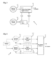
- FIG. 1 An example of a prior art solution for this problem is depicted in FIG. 1 .
- the redundant sensor 5 includes a first sensing element 6-1 and a second sensing element 6-2.
- the reference numeral "6" is a general reference to a sensing element, and 6-X is to a specific sensing element. Further, this convention is generally used herein).
- Each sensing element 6 is oriented in a sensing environment (i.e., an environment for sensing of ambient conditions).
- Each sensing element 6-1, 6-2 is coupled to a respective sensing circuit 8, such as integrated circuit (IC) 8-1, 8-2.
- IC integrated circuit
- Each sensing circuit 8 provides for powering the sensing element 6, signal receipt, amplification and the like.
- Each sensing circuit 8 (referred to hereafter as “IC,” merely for convenience) communicates data to another device, such as digital bus combiner 3.
- the digital bus combiner 3 may then communicate data from the sensors 2 to yet another system.
- the digital bus combiner 3 takes the data from each IC 8, and places the data onto a common digital output bus (not shown).
- a system that makes use of the data will receive a single message that contains data from each of the two sensors.
- a comparison may be made by the system to determine if the sensors provide adequately correlated data.
- this type of arrangement may work adequately. That is, under static conditions, this type of combining scheme may be adequate. However, under dynamic conditions, such as where the sensors are measuring liquid fuel pressure, there may be constant pulsations or slewing pressures in the system. If the two (or more) sensors are operating asynchronously, they will measure the pressure at different times. The digital bus combiner 3 will take the asynchronous data, combine it into one communications packet, and send it to the system. If the sampling delay between the two samples is long enough, then the sensors may have properly measured pressure at two very different levels. A system comparison of those two asynchronous samples may show a significant discrepancy, inadvertently causing a false report of a faulty sensor.
- a sensor in a first embodiment, includes at least two sensing elements configured for asynchronously sensing a stimulus and providing sensed data; a clock configured to provide a time for each sensing; at least one signal conditioning circuit configured to provide conditioned data from the sensed data; and, a combiner circuit configured to provide a digital data sequence that includes at least one of the conditioned data and the time between the sensed data.
- At least one of the signal conditioning circuits includes electronics for operating a respective sensing element.
- the sensor further includes at least one sensing circuit for controlling the sensing, and in some further embodiments, at least one of the sensing circuits is configured to receive a current time.
- at least one of a sensing circuit, the signal conditioning circuit and the combiner circuit is configured to at least one of receive the sensed data, receive time from the clock, associate a sensing time with the sensed data, and provide combined data.
- the at least two sensing elements are configured to sense at least one of temperature and pressure.
- the signal conditioning circuit is configured to compensate the sensed data for an influencing factor.
- at least one of a sensing circuit, the signal conditioning circuit and the combiner circuit is configured to overwrite data with a predetermined value.
- a sensor in a second embodiment, includes: at least two sensing elements configured for synchronously sensing a stimulus and providing sensed data; at least one signal conditioning circuit configured to provide conditioned data from the sensed data; and, a combiner circuit configured to provide a digital data sequence that includes the conditioned data.
- the senor further includes a controller for initiating the sensing, and the controller may include a clock.
- at least one of the signal conditioning circuits comprises electronics for operating a respective sensing element.
- the sensor further includes at least one sensing circuit for controlling the sensing.
- at least one of a sensing circuit, the signal conditioning circuit and the combiner circuit is configured to at least one of receive the sensed data, receive time from a clock, associate a sensing time with the sensed data, and provide combined data.
- at least two sensing elements are configured to sense at least one of temperature and pressure.
- the signal conditioning circuit is configured to compensate the sensed data for an influencing factor.
- at least one of a sensing circuit, the signal conditioning circuit and the combiner circuit is configured to overwrite data with a predetermined value.
- a method for providing combined data from a redundant sensor includes receiving sensed data from each of at least two sensing elements; receiving time data that correlates to a sampling time for each of the at least two sensing elements; associating the time data with the sensed data to provide combined data; and conditioning the combined data to provide conditioned data.
- the method further includes generating the current time with at least one of a digital counter, a digital communication, and a phase-lock-loop correlation. In some embodiments, the method further includes initiating sampling according to the current time. In some embodiments, the method further includes overwriting a register comprising one of sensed data, time data, combined data and conditioned data with a predetermined value. In some embodiments, conditioning includes at least one of accepting, adjusting and rejecting the combined data.
- the redundant sensor is configured for sensing pressure.
- the redundant sensor which may be used for sensing other conditions (such as temperature), provides temporal correlation of data between sensing elements thus reducing false reporting of sensor faults, and increasing the reliability of sensor data.
- the redundant sensor is adapted for industrial use, such as in settings where a long useful life in a harsh environment is required.
- the redundant sensor 10 includes a first sensing element 6-1 and a second sensing element 6-2.
- Each sensing element 6 is configured to be oriented in a sensing environment (i.e., an environment for sensing of ambient conditions).
- Each sensing element 6 is coupled to respective sensing circuit 8, such as an integrated circuit (IC) 8-1, 8-2.
- IC integrated circuit
- Each of the sensing circuits 8 provides for powering the sensing element 6, signal receipt, amplification and the like.
- Each sensing circuit 8 (referred to hereafter as "IC,” merely for convenience) communicates data to another device, such as digital bus controller 3.
- the digital bus combiner 14 may then communicate data from the sensors 2 to yet another system.
- the digital bus combiner 14 includes a clock. On an ongoing basis, the digital bus combiner 14 provides the current time to each of the respective ICs, 8-1, 8-2. Each IC, 8-1, 8-2, associates the current time with current sample data. Stated another way, each IC, 8-1, 8-2, may "time-stamp" the sensor data. The sensor data is then communicated to the digital bus combiner 14. The digital bus combiner 14 will then combine the sensor data as appropriate and pass the combined data (i.e., a data set that includes time-stamped data from each of the sensing elements 6).
- the redundant sensor 10 may accommodate a plurality of sensing elements 6. Further, a variety of components may be used as sensing elements 6, as well as supporting electronics and digital bus combiners 14. In addition, the redundant sensor 10 may accommodate sensing of diverse data, such as pressure and temperature. In short, embodiments of the redundant sensor 10 may practically only be limited by needs or constraints of a user, designer, manufacturer, or other similarly interested party.
- FIG. 3 Another embodiment is provided in FIG. 3 .
- a first IC 18 (or "master") fulfills the role of the sensing circuit 8-1, as well as the role of the digital bus combiner 14.
- the first IC 18 sends the clock signal (i.e., current time) to a second IC 19 (or “slave”).
- the second IC 19 receives the current time, time-stamps data from the sensing element 6-2, and sends the time-stamped sensor data to the first IC 18.
- the first IC 18 makes use of the current time to time-stamp sensor data from the respective sensing element 6-1.
- the first IC 18 will appropriately combine the time-stamped sensor data as appropriate and pass the combined data.
- first IC 18 and the second IC 19 be of different types. That is, the first IC 18 and the second IC 19 could both be of the same design, and simply configured differently, such as through wiring, programming, and the like.
- the clock mechanism may be provided in a variety of ways.
- the clock may be a sampling clock where a rising or falling edge is a signal to initiate sampling.
- the clock may be a slow clock in which each IC 8 has an internal phase-lock-loop (PLL) to phase lock onto slow clock.
- the clock may rely on a digital signal, such as one communicated from the digital bus combiners 14.
- the timestamp may be generated by a free-running digital counter, such as in the digital bus combiner 14.
- the counter Upon receiving a sensor signal from either channel (i.e., either sensing element), the counter is read and the value may then be associated with the corresponding sensor data.
- the redundant sensor 10 includes at least two sensing elements 6.
- the at least two sensing elements 6 are configured to sense the same property of a common stimulus.
- the output of the at least two sensing elements 6 is then sampled asynchronously as seen by the timing notations t sample and t sample + ⁇ .
- the sampled signals from the at least two sensing elements 6 are then processed by at least one signal conditioning circuit 41 (41-1,41-2) before being passed to the digital bus combiner 14. Again the digital bus combiner 14 produces a single digital data sequence.
- the digital bus combiner 14 also receives at least one timing signal.
- the at least one timing signal includes enough information to determine a time difference between the sampled signals.
- the difference in time between samples of the signals along with the known fastest rate of change for the input stimulus may then be used to determine the allowed un-faulted difference between conditioned signals.
- asynchronous sampling involves the sampling of two or more signals with a large time delay between each of the sample intervals.
- the difference in timing can be considered large if it is of similar order of magnitude to or greater than the minimum timing resolution of the system based upon required input bandwidth or resolution of fastest input transient events.
- Asynchronous timing can take the form of timing offset between sampled signals or differences in sampling periods.
- the signal conditioning circuit 41 is a circuit that transforms a signal from one of the sensing elements 6 into a "conditioned signal.”
- a “conditioned signal” is a signal that contains desired properties of an output response.
- the "conditioned signal” includes data from the at least one sensing element 6, wherein that data has been adjusted to account for at least one influencing factor.
- An example of signal conditioning includes thermal compensation of a sampled signal, such that signal data is relatively constant with respect to temperature.
- each of the at least one signal conditioning circuit 41 may include at least one form of "conditioning data.”
- the conditioning data may be presented as a data table, as a polynomial function and in other similarly useful forms.
- the signal conditioning circuit 41 may therefore include at least one input from an external component, such as a temperature sensor.
- an external component such as a temperature sensor.
- Each of the sensing circuits 8-1, 8-2 (as well as the first IC 18 and the second IC 19) may serve as the signal conditioning circuit 41.
- the redundant sensor 10 includes at least two sensing elements 6.
- the sensing elements 6 sense the same property of a common stimulus.
- the output of these sensing elements 6 is then sampled synchronously as indicated by the timing notations t sample and t sample + ⁇ .
- Sampled signals from the sensing elements 6 are then processed by a respective signal conditioning circuit 41 before being passed to the digital bus combiner 14.
- the digital bus combiner 14 produces a single digital data sequence.
- the digital bus combiner 14 does not receive a timing signal because the sensing elements 6 are sampled synchronously.
- the magnitude of the allowed difference between samples for determining un-faulted signals can be a constant that is predetermined.
- synchronous sampling involves the sampling of two or more signals with a small difference in timing.
- the difference in timing can be considered small if the difference is considered to be significantly less than the timing resolution required to observe the fastest input transient events.
- a difference in timing can be considered small if the difference is considered to be significantly less than the period associated with the required maximum system bandwidth.
- bit sequence (e.g., all zeros) may be stored in a periodically updated register immediately after executing a transfer of the contents of the register. Should the bit sequence be received by a receiving system, the bit sequence will be recognized as containing invalid data.
- An exemplary embodiment is provided, and may be considered in conjunction with FIG. 6 .
- output of data is provided as follows. First, digital information packet, N, populates Register A (through serial or parallel transfer). The digital information packet, N, is then copied to Register B in parallel. At this point, Register A is overwritten to the predetermined specific value. This may be accomplished through use of another circuit path to Register A. The digital information packet, N, is then sent out serially on a digital bus, and in some cases, may be validated by a receiving system that has valid data (such as through CRC, signal plausibility, or the like). Next, another digital information packet, N+1, populates Register A, overwriting the previous content, and the process repeats.
- the output register may be serially populated and serially depopulated.
- the output register may be parallel populated and serially depopulated.
- this solution enables the receiving system to detect the sensor based fault, and further enhances detectability of a fault.
- the redundant sensor 10 which produces time-stamped data, enables a receiving system to make informed decisions about the environment as well as the health of sensing elements. For example, if the time-stamp between two data points is very short, it may be reasonable to compare the data with relative confidence. However, if the time-stamp reflects a relatively long interval, the system may accept, adjust or reject the data. Additionally, time-stamped data may also be used to monitor or assess the functionality of the sensing elements.
- receiving systems may be configured to make use of the combined data in ways previously not available.
- algorithm(s) may be employed to interpolate data through averaging of the data, line-fitting of the data and the like.
- the redundant sensor 10 may be used with sensors that have been configured for harsh environments, frequent sampling and the like.
- the redundant sensor 10 includes at least one of a surface mount device (SMD) thermistor, a thermocouple or another type of temperature sensor.
- the redundant sensor 10 may include at least one of a pressure sensor that is configured to measure absolute pressure and/or gage pressure.
- the pressure sensor includes a capacitive sensing element. In these embodiments, deflection of at least a portion of the capacitive element (due to pressure exerted thereon) results in a change to an output signal from the element. The change in the output signal can be correlated to the exerted pressure.
Landscapes
- Physics & Mathematics (AREA)
- General Physics & Mathematics (AREA)
- Engineering & Computer Science (AREA)
- Chemical & Material Sciences (AREA)
- Analytical Chemistry (AREA)
- Theoretical Computer Science (AREA)
- Biomedical Technology (AREA)
- Health & Medical Sciences (AREA)
- General Engineering & Computer Science (AREA)
- Testing Or Calibration Of Command Recording Devices (AREA)
- Measuring Pulse, Heart Rate, Blood Pressure Or Blood Flow (AREA)
- Arrangements For Transmission Of Measured Signals (AREA)
- Measuring Fluid Pressure (AREA)
Abstract
Description
- The invention disclosed herein relates to redundant use of sensors such as temperature sensors or pressure sensors, and in particular, provides for coordination of redundant sensing.
- A variety of industrial processes call for knowledge of ambient temperature and pressure conditions. For example, in automotive systems, it is desirable to know pressure and temperature of gasses so that combustion may be more efficiently controlled. A number of sensors have been devised to address this need.
- Generally, these sensors provide for monitoring of at least one of temperature and pressure on an ongoing basis. In some embodiments, the sensors are adapted for harsh environments. As one might surmise, some of these sensors are complicated (and therefore costly) devices.
- It is widely recognized that the more complicated a device becomes, the more prone to failure it will be. Accordingly, some environmental sampling protocols call for use of redundant sensors.
- Redundant sampling allows the system using the sensors to compare output of two (or more) sensors and to determine validity of the sensor measurement(s). In theory, single point faults on one sensor will not affect the output of the other sensor. If data from the two sensor measurements is in agreement, the system can make a reasonable assumption that both sensors are working properly. If data from the two (or more) sensors does not agree, the system can make a reasonable assumption that at least one of the sensors is faulted.
- An example of a prior art solution for this problem is depicted in
FIG. 1 . InFIG. 1 , an embodiment of aredundant sensor 5 is shown. In this example, theredundant sensor 5 includes a first sensing element 6-1 and a second sensing element 6-2. (Note that for simplicity, the reference numeral "6" is a general reference to a sensing element, and 6-X is to a specific sensing element. Further, this convention is generally used herein). Each sensing element 6 is oriented in a sensing environment (i.e., an environment for sensing of ambient conditions). Each sensing element 6-1, 6-2 is coupled to a respective sensing circuit 8, such as integrated circuit (IC) 8-1, 8-2. Each sensing circuit 8 provides for powering the sensing element 6, signal receipt, amplification and the like. Each sensing circuit 8 (referred to hereafter as "IC," merely for convenience) communicates data to another device, such as digital bus combiner 3. Thedigital bus combiner 3 may then communicate data from thesensors 2 to yet another system. - Generally, in an embodiment such as the one shown in
Fig. 1 , thedigital bus combiner 3 takes the data from each IC 8, and places the data onto a common digital output bus (not shown). A system that makes use of the data will receive a single message that contains data from each of the two sensors. A comparison may be made by the system to determine if the sensors provide adequately correlated data. - Generally, this type of arrangement may work adequately. That is, under static conditions, this type of combining scheme may be adequate. However, under dynamic conditions, such as where the sensors are measuring liquid fuel pressure, there may be constant pulsations or slewing pressures in the system. If the two (or more) sensors are operating asynchronously, they will measure the pressure at different times. The
digital bus combiner 3 will take the asynchronous data, combine it into one communications packet, and send it to the system. If the sampling delay between the two samples is long enough, then the sensors may have properly measured pressure at two very different levels. A system comparison of those two asynchronous samples may show a significant discrepancy, inadvertently causing a false report of a faulty sensor. - Thus, what are needed are methods and apparatus to provide for correlation of data between two or more sensors, where the data is provided in an ongoing basis. Preferably, the methods and apparatus greatly reduce false positive reporting of sensor faults.
- In a first embodiment, a sensor is provided. The sensor includes at least two sensing elements configured for asynchronously sensing a stimulus and providing sensed data; a clock configured to provide a time for each sensing; at least one signal conditioning circuit configured to provide conditioned data from the sensed data; and, a combiner circuit configured to provide a digital data sequence that includes at least one of the conditioned data and the time between the sensed data.
- With regards to the first embodiment, in some embodiments thereof, at least one of the signal conditioning circuits includes electronics for operating a respective sensing element. In some embodiments, the sensor further includes at least one sensing circuit for controlling the sensing, and in some further embodiments, at least one of the sensing circuits is configured to receive a current time. In some embodiments, at least one of a sensing circuit, the signal conditioning circuit and the combiner circuit is configured to at least one of receive the sensed data, receive time from the clock, associate a sensing time with the sensed data, and provide combined data. In some embodiments, the at least two sensing elements are configured to sense at least one of temperature and pressure. In some embodiments, the signal conditioning circuit is configured to compensate the sensed data for an influencing factor. In some embodiments, at least one of a sensing circuit, the signal conditioning circuit and the combiner circuit is configured to overwrite data with a predetermined value.
- In a second embodiment, a sensor is provided and includes: at least two sensing elements configured for synchronously sensing a stimulus and providing sensed data; at least one signal conditioning circuit configured to provide conditioned data from the sensed data; and, a combiner circuit configured to provide a digital data sequence that includes the conditioned data.
- With regards to the second embodiment, in some embodiments thereof, the sensor further includes a controller for initiating the sensing, and the controller may include a clock. In some embodiments, at least one of the signal conditioning circuits comprises electronics for operating a respective sensing element. In some embodiments, the sensor further includes at least one sensing circuit for controlling the sensing. In some embodiments, at least one of a sensing circuit, the signal conditioning circuit and the combiner circuit is configured to at least one of receive the sensed data, receive time from a clock, associate a sensing time with the sensed data, and provide combined data. In some embodiments, at least two sensing elements are configured to sense at least one of temperature and pressure. In some embodiments, the signal conditioning circuit is configured to compensate the sensed data for an influencing factor. In some embodiments, at least one of a sensing circuit, the signal conditioning circuit and the combiner circuit is configured to overwrite data with a predetermined value.
- In a further embodiment, a method for providing combined data from a redundant sensor is provided. The method includes receiving sensed data from each of at least two sensing elements; receiving time data that correlates to a sampling time for each of the at least two sensing elements; associating the time data with the sensed data to provide combined data; and conditioning the combined data to provide conditioned data.
- With regards to the further embodiments, in some embodiments thereof, the method further includes generating the current time with at least one of a digital counter, a digital communication, and a phase-lock-loop correlation. In some embodiments, the method further includes initiating sampling according to the current time. In some embodiments, the method further includes overwriting a register comprising one of sensed data, time data, combined data and conditioned data with a predetermined value. In some embodiments, conditioning includes at least one of accepting, adjusting and rejecting the combined data.
- The features and advantages of the invention are apparent from the following description taken in conjunction with the accompanying drawings in which:
-
FIG. 1 is a flow chart depicting aspects of a prior art redundant sensor; -
FIGS. 2 through 5 are flow charts depicting embodiments of a redundant sensor according to the teachings herein; and, -
FIG. 6 depicts a relationship of data storage registers for transmission of data from the redundant sensor. - Disclosed herein is a redundant sensor. In the exemplary embodiment, the redundant sensor is configured for sensing pressure. The redundant sensor, which may be used for sensing other conditions (such as temperature), provides temporal correlation of data between sensing elements thus reducing false reporting of sensor faults, and increasing the reliability of sensor data. Generally, the redundant sensor is adapted for industrial use, such as in settings where a long useful life in a harsh environment is required.
- Refer now to
FIG. 2 , which provides a flow chart depicting aspects of an exemplaryredundant sensor 10. In this example, theredundant sensor 10 includes a first sensing element 6-1 and a second sensing element 6-2. Each sensing element 6 is configured to be oriented in a sensing environment (i.e., an environment for sensing of ambient conditions). Each sensing element 6 is coupled to respective sensing circuit 8, such as an integrated circuit (IC) 8-1, 8-2. Each of the sensing circuits 8 provides for powering the sensing element 6, signal receipt, amplification and the like. Each sensing circuit 8 (referred to hereafter as "IC," merely for convenience) communicates data to another device, such asdigital bus controller 3. Thedigital bus combiner 14 may then communicate data from thesensors 2 to yet another system. - In the embodiment depicted in
FIG. 2 , thedigital bus combiner 14 includes a clock. On an ongoing basis, thedigital bus combiner 14 provides the current time to each of the respective ICs, 8-1, 8-2. Each IC, 8-1, 8-2, associates the current time with current sample data. Stated another way, each IC, 8-1, 8-2, may "time-stamp" the sensor data. The sensor data is then communicated to thedigital bus combiner 14. Thedigital bus combiner 14 will then combine the sensor data as appropriate and pass the combined data (i.e., a data set that includes time-stamped data from each of the sensing elements 6). - It should be noted that the
redundant sensor 10 may accommodate a plurality of sensing elements 6. Further, a variety of components may be used as sensing elements 6, as well as supporting electronics anddigital bus combiners 14. In addition, theredundant sensor 10 may accommodate sensing of diverse data, such as pressure and temperature. In short, embodiments of theredundant sensor 10 may practically only be limited by needs or constraints of a user, designer, manufacturer, or other similarly interested party. - Another embodiment is provided in
FIG. 3 . As shown inFIG. 3 , the duties of thedigital bus combiner 14 have been re-assigned. That is, inFIG. 3 , a first IC 18 (or "master") fulfills the role of the sensing circuit 8-1, as well as the role of thedigital bus combiner 14. In this embodiment, thefirst IC 18 sends the clock signal (i.e., current time) to a second IC 19 (or "slave"). In turn, thesecond IC 19 receives the current time, time-stamps data from the sensing element 6-2, and sends the time-stamped sensor data to thefirst IC 18. Similarly, thefirst IC 18 makes use of the current time to time-stamp sensor data from the respective sensing element 6-1. Thefirst IC 18 will appropriately combine the time-stamped sensor data as appropriate and pass the combined data. - In this embodiment, it is not required that the
first IC 18 and thesecond IC 19 be of different types. That is, thefirst IC 18 and thesecond IC 19 could both be of the same design, and simply configured differently, such as through wiring, programming, and the like. - The clock mechanism may be provided in a variety of ways. For example, the clock may be a sampling clock where a rising or falling edge is a signal to initiate sampling. The clock may be a slow clock in which each IC 8 has an internal phase-lock-loop (PLL) to phase lock onto slow clock. The clock may rely on a digital signal, such as one communicated from the
digital bus combiners 14. The timestamp may be generated by a free-running digital counter, such as in thedigital bus combiner 14. Upon receiving a sensor signal from either channel (i.e., either sensing element), the counter is read and the value may then be associated with the corresponding sensor data. - Some additional embodiments of the
redundant sensor 10 are provided inFIGS. 4 and5 . As shown inFIG. 4 , theredundant sensor 10 includes at least two sensing elements 6. The at least two sensing elements 6 are configured to sense the same property of a common stimulus. The output of the at least two sensing elements 6 is then sampled asynchronously as seen by the timing notations tsample and tsample + δ. The sampled signals from the at least two sensing elements 6 are then processed by at least one signal conditioning circuit 41 (41-1,41-2) before being passed to thedigital bus combiner 14. Again thedigital bus combiner 14 produces a single digital data sequence. Thedigital bus combiner 14 also receives at least one timing signal. Generally, the at least one timing signal includes enough information to determine a time difference between the sampled signals. The difference in time between samples of the signals along with the known fastest rate of change for the input stimulus may then be used to determine the allowed un-faulted difference between conditioned signals. - Comparatively speaking, asynchronous sampling involves the sampling of two or more signals with a large time delay between each of the sample intervals. The difference in timing can be considered large if it is of similar order of magnitude to or greater than the minimum timing resolution of the system based upon required input bandwidth or resolution of fastest input transient events. Asynchronous timing can take the form of timing offset between sampled signals or differences in sampling periods.
- Generally, the signal conditioning circuit 41 is a circuit that transforms a signal from one of the sensing elements 6 into a "conditioned signal." A "conditioned signal" is a signal that contains desired properties of an output response. Stated another way, the "conditioned signal" includes data from the at least one sensing element 6, wherein that data has been adjusted to account for at least one influencing factor. An example of signal conditioning includes thermal compensation of a sampled signal, such that signal data is relatively constant with respect to temperature. Accordingly, each of the at least one signal conditioning circuit 41 may include at least one form of "conditioning data." The conditioning data may be presented as a data table, as a polynomial function and in other similarly useful forms. It should be understood that the signal conditioning circuit 41 may therefore include at least one input from an external component, such as a temperature sensor. Each of the sensing circuits 8-1, 8-2 (as well as the
first IC 18 and the second IC 19) may serve as the signal conditioning circuit 41. - In the embodiment of
FIG. 5 , theredundant sensor 10 includes at least two sensing elements 6. The sensing elements 6 sense the same property of a common stimulus. The output of these sensing elements 6 is then sampled synchronously as indicated by the timing notations tsample and tsample + δ. Sampled signals from the sensing elements 6 are then processed by a respective signal conditioning circuit 41 before being passed to thedigital bus combiner 14. Thedigital bus combiner 14 produces a single digital data sequence. In this embodiment of theredundant sensor 10, thedigital bus combiner 14 does not receive a timing signal because the sensing elements 6 are sampled synchronously. As a result of synchronous sampling, the magnitude of the allowed difference between samples for determining un-faulted signals can be a constant that is predetermined. - Generally, "synchronous sampling" involves the sampling of two or more signals with a small difference in timing. The difference in timing can be considered small if the difference is considered to be significantly less than the timing resolution required to observe the fastest input transient events. Similarly, a difference in timing can be considered small if the difference is considered to be significantly less than the period associated with the required maximum system bandwidth.
- Further reductions in false reporting of erroneous data may be realized through an enhanced communications technique useful in digital embodiments. More specifically, a known bit sequence (e.g., all zeros) may be stored in a periodically updated register immediately after executing a transfer of the contents of the register. Should the bit sequence be received by a receiving system, the bit sequence will be recognized as containing invalid data. An exemplary embodiment is provided, and may be considered in conjunction with
FIG. 6 . - In one embodiment, output of data is provided as follows. First, digital information packet, N, populates Register A (through serial or parallel transfer). The digital information packet, N, is then copied to Register B in parallel. At this point, Register A is overwritten to the predetermined specific value. This may be accomplished through use of another circuit path to Register A. The digital information packet, N, is then sent out serially on a digital bus, and in some cases, may be validated by a receiving system that has valid data (such as through CRC, signal plausibility, or the like). Next, another digital information packet, N+1, populates Register A, overwriting the previous content, and the process repeats.
- Accordingly, observability of a specific low probability fault in digital data transmission for a pressure sensor (DFMEA to detection) is improved.
- Various embodiments may be practiced. For example, in one embodiment, the output register may be serially populated and serially depopulated. In another embodiment, the output register may be parallel populated and serially depopulated.
- In the event that a fault inhibits updating the output register, this solution enables the receiving system to detect the sensor based fault, and further enhances detectability of a fault.
- Accordingly, provided herein are methods and apparatus where individual sensors or sensor subsystems may be configured to asynchronously sample an environment. The
redundant sensor 10, which produces time-stamped data, enables a receiving system to make informed decisions about the environment as well as the health of sensing elements. For example, if the time-stamp between two data points is very short, it may be reasonable to compare the data with relative confidence. However, if the time-stamp reflects a relatively long interval, the system may accept, adjust or reject the data. Additionally, time-stamped data may also be used to monitor or assess the functionality of the sensing elements. - Further, receiving systems may be configured to make use of the combined data in ways previously not available. For example, algorithm(s) may be employed to interpolate data through averaging of the data, line-fitting of the data and the like.
- It should be recognized that a variety of integrated circuits, sensing elements and other components may be used in the
redundant sensor 10. Additionally, the sampling frequency, parameters or conditions for which sampling is conducted, sampling ranges and the like need not be limited. For example, theredundant sensor 10 may be used with sensors that have been configured for harsh environments, frequent sampling and the like. - For example, in some embodiments, the
redundant sensor 10 includes at least one of a surface mount device (SMD) thermistor, a thermocouple or another type of temperature sensor. Theredundant sensor 10 may include at least one of a pressure sensor that is configured to measure absolute pressure and/or gage pressure. In some embodiments, the pressure sensor includes a capacitive sensing element. In these embodiments, deflection of at least a portion of the capacitive element (due to pressure exerted thereon) results in a change to an output signal from the element. The change in the output signal can be correlated to the exerted pressure. - It should be recognized that the teachings herein are merely illustrative and are not limiting of the invention. Further, one skilled in the art will recognize that additional components, configurations, arrangements and the like may be realized while remaining within the scope of this invention. For example, configurations of sensors, circuitry and the like may be varied from embodiments disclosed herein. Generally, design and/or application of components of the redundant sensor is limited only by the needs of a system designer, manufacturer, operator and/or user and demands presented in any particular situation.
- Various other components may be included and called upon for providing for aspects of the teachings herein. For example, additional materials, combinations of materials and/or omission of materials may be used to provide for added embodiments that are within the scope of the teachings herein.
- When introducing elements of the present invention or the embodiment(s) thereof, the articles "a," "an," and "the" are intended to mean that there are one or more of the elements. Similarly, the adjective "another," when used to introduce an element, is intended to mean one or more elements. The terms "including" and "having" are intended to be inclusive such that there may be additional elements other than the listed elements.
- In the present application a variety of variables are described, including but not limited to components, conditions, and performance characteristics. It is to be understood that any combination of any of these variables can define an embodiment of the invention. For example, a combination of a particular material for the body, with a set of sensors, under a particular range of a given environmental condition, but the specific combination might not be expressly stated, is an embodiment of the invention. Other combinations of articles, components, conditions, and/or methods can also be specifically selected from among variables listed herein to define other embodiments, as would be apparent to those of ordinary skill in the art.
- While the invention has been described with reference to exemplary embodiments, it will be understood by those skilled in the art that various changes may be made and equivalents may be substituted for elements thereof without departing from the scope of the invention. In addition, many modifications will be appreciated by those skilled in the art to adapt a particular instrument, situation or material to the teachings of the invention without departing from the essential scope thereof. Therefore, it is intended that the invention not be limited to the particular embodiment disclosed as the best mode contemplated for carrying out this invention, but that the invention will include all embodiments falling within the scope of the appended claims.
Claims (14)
- A sensor (10) comprising:at least two sensing elements (6) configured for synchronously sensing a stimulus and providing sensed data;at least one signal conditioning circuit (41) configured to provide conditioned data from the sensed data; and,a combiner circuit (14) configured to provide a digital data sequence that includes the conditioned data.
- The sensor (10) as in claim 1, further comprising a controller (3) for initiating the sensing.
- The sensor (10) as in claim 2, wherein the controller (3) comprises a clock.
- The sensor (10) as in claim 1, wherein at least one signal conditioning circuit (41) comprises electronics for operating a respective sensing element (6).
- The sensor (10) as in claim 1, further comprising at least one sensing circuit (8) for controlling the sensing.
- The sensor (10) as in claim 1, wherein at least one of a sensing circuit (8), the signal conditioning circuit (41) and the combiner circuit (14) is configured to at least one of receive the sensed data, receive time from a clock, associate a sensing time with the sensed data, and provide combined data.
- The sensor (10) as in claim 1, wherein the at least two sensing elements (6) are configured to sense at least one of temperature and pressure.
- The sensor (10) as in claim 1, wherein the signal conditioning circuit (41) is configured to compensate the sensed data for an influencing factor.
- The sensor (10) as in claim 1, wherein at least one of a sensing circuit (8), the signal conditioning circuit and the combiner circuit (14) is configured to overwrite data with a predetermined value.
- A method for providing combined data from a redundant sensor, the method comprising:receiving sensed data from each of at least two sensing elements (6);receiving time data that correlates to a sampling time for each of the at least two sensing elements;associating the time data with the sensed data to provide combined data; andconditioning the combined data to provide conditioned data.
- The method as in claim 10, further comprising generating the current time with at least one of a digital counter, a digital communication, and a phase-lock-loop correlation.
- The method as in claim 10, further comprising initiating sampling according to the current time.
- The method as in claim 10, further comprising overwriting a register comprising one of sensed data, time data, combined data and conditioned data with a predetermined value.
- The method as in claim 10, wherein conditioning comprises at least one of accepting, adjusting and rejecting the combined data.
Applications Claiming Priority (1)
| Application Number | Priority Date | Filing Date | Title |
|---|---|---|---|
| US13/788,779 US20140257729A1 (en) | 2013-03-07 | 2013-03-07 | Time synchronized redundant sensors |
Publications (3)
| Publication Number | Publication Date |
|---|---|
| EP2775264A2 true EP2775264A2 (en) | 2014-09-10 |
| EP2775264A3 EP2775264A3 (en) | 2014-12-10 |
| EP2775264A8 EP2775264A8 (en) | 2016-03-16 |
Family
ID=50238229
Family Applications (1)
| Application Number | Title | Priority Date | Filing Date |
|---|---|---|---|
| EP20140158409 Withdrawn EP2775264A3 (en) | 2013-03-07 | 2014-03-07 | Time synchronized redundant sensors |
Country Status (5)
| Country | Link |
|---|---|
| US (1) | US20140257729A1 (en) |
| EP (1) | EP2775264A3 (en) |
| JP (1) | JP2014174168A (en) |
| KR (1) | KR20140110796A (en) |
| CN (1) | CN104038333A (en) |
Cited By (3)
| Publication number | Priority date | Publication date | Assignee | Title |
|---|---|---|---|---|
| WO2016057289A1 (en) * | 2014-10-09 | 2016-04-14 | Invensense, Inc. | System and method for mems sensor system synchronization |
| EP3136681B1 (en) * | 2015-08-27 | 2021-08-04 | Yokogawa Electric Corporation | Wireless relay device, wireless communication system, and wireless communication method |
| WO2023230630A1 (en) * | 2022-05-26 | 2023-11-30 | Certus Critical Care, Inc. | Solid state sensor |
Families Citing this family (15)
| Publication number | Priority date | Publication date | Assignee | Title |
|---|---|---|---|---|
| US20140257730A1 (en) * | 2013-03-11 | 2014-09-11 | Qualcomm Incorporated | Bandwidth and time delay matching for inertial sensors |
| US9625558B2 (en) * | 2014-03-17 | 2017-04-18 | Lsis Co., Ltd. | Duplex system |
| US10578465B2 (en) * | 2015-02-03 | 2020-03-03 | Infineon Technologies Ag | Sensor bus system and unit with internal event verification |
| JP2018534686A (en) * | 2015-10-23 | 2018-11-22 | クアルコム,インコーポレイテッド | Apparatus and method for synchronizing controllers and sensors |
| DE102015121910A1 (en) * | 2015-12-16 | 2017-06-22 | Robert Bosch Automotive Steering Gmbh | Method for checking the plausibility of sensor signals, in particular in steering systems |
| US10719107B2 (en) | 2016-03-29 | 2020-07-21 | Intel Corporation | Method and apparatus to maintain node power budget for systems that share a power supply |
| US9813783B2 (en) | 2016-04-01 | 2017-11-07 | Intel Corporation | Multi-camera dataset assembly and management with high precision timestamp requirements |
| CN107588886A (en) * | 2016-07-06 | 2018-01-16 | 北京空间技术研制试验中心 | Bimodulus atmospheric pressure measurement device |
| JP6348163B2 (en) * | 2016-12-15 | 2018-06-27 | ファナック株式会社 | Control device and control system |
| CN107631828A (en) * | 2017-09-13 | 2018-01-26 | 南京航伽电子科技有限公司 | Double pressure transmitter breakdown judges and switching method |
| JP2019200067A (en) * | 2018-05-14 | 2019-11-21 | 横河電機株式会社 | Measuring system, measuring method, and pressure measuring device |
| JP6928705B2 (en) * | 2018-05-14 | 2021-09-01 | 横河電機株式会社 | Measuring system, measuring method and pressure measuring device |
| EP3726340B1 (en) * | 2019-04-15 | 2022-08-10 | NXP USA, Inc. | Wake-up circuit and methodology for reducing false wake-up events |
| CN110141207B (en) * | 2019-06-10 | 2022-02-25 | 出门问问信息科技有限公司 | Heart rate detection debugging method, device, storage medium and computer program product |
| CN121325550B (en) * | 2025-12-04 | 2026-04-07 | 北京康吉森技术有限公司 | Clock synchronous control method and system of multiple redundancy control system |
Family Cites Families (8)
| Publication number | Priority date | Publication date | Assignee | Title |
|---|---|---|---|---|
| US4771427A (en) * | 1986-10-02 | 1988-09-13 | United Technologies Corporation | Equalization in redundant channels |
| US5457988A (en) * | 1993-10-28 | 1995-10-17 | Panex Corporation | Side pocket mandrel pressure measuring system |
| US6434456B1 (en) * | 2000-09-07 | 2002-08-13 | Kelsey-Hayes Company | High reliability pressure sensor |
| US6556939B1 (en) * | 2000-11-22 | 2003-04-29 | Smartsignal Corporation | Inferential signal generator for instrumented equipment and processes |
| DE202009017430U1 (en) * | 2009-12-23 | 2011-05-05 | Liebherr-Werk Ehingen Gmbh | sensor |
| JP5530175B2 (en) * | 2009-12-25 | 2014-06-25 | キヤノンアネルバ株式会社 | Vacuum processing equipment |
| US20130073189A1 (en) * | 2010-06-11 | 2013-03-21 | Toyota Jidosha Kabushiki Kaisha | Control apparatus for internal combustion engine |
| DE102010030488A1 (en) * | 2010-06-24 | 2011-12-29 | Endress + Hauser Conducta Gesellschaft für Mess- und Regeltechnik mbH + Co. KG | Method for adjusting a measuring device in process analysis technology |
-
2013
- 2013-03-07 US US13/788,779 patent/US20140257729A1/en not_active Abandoned
-
2014
- 2014-03-05 JP JP2014042266A patent/JP2014174168A/en active Pending
- 2014-03-07 EP EP20140158409 patent/EP2775264A3/en not_active Withdrawn
- 2014-03-07 CN CN201410113724.7A patent/CN104038333A/en active Pending
- 2014-03-07 KR KR20140027353A patent/KR20140110796A/en not_active Withdrawn
Non-Patent Citations (1)
| Title |
|---|
| None |
Cited By (6)
| Publication number | Priority date | Publication date | Assignee | Title |
|---|---|---|---|---|
| WO2016057289A1 (en) * | 2014-10-09 | 2016-04-14 | Invensense, Inc. | System and method for mems sensor system synchronization |
| CN107005242A (en) * | 2014-10-09 | 2017-08-01 | 应美盛股份有限公司 | System and method for mems sensor system synchronization |
| US10180340B2 (en) | 2014-10-09 | 2019-01-15 | Invensense, Inc. | System and method for MEMS sensor system synchronization |
| CN107005242B (en) * | 2014-10-09 | 2021-02-09 | 应美盛股份有限公司 | System and method for MEMS sensor system synchronization |
| EP3136681B1 (en) * | 2015-08-27 | 2021-08-04 | Yokogawa Electric Corporation | Wireless relay device, wireless communication system, and wireless communication method |
| WO2023230630A1 (en) * | 2022-05-26 | 2023-11-30 | Certus Critical Care, Inc. | Solid state sensor |
Also Published As
| Publication number | Publication date |
|---|---|
| KR20140110796A (en) | 2014-09-17 |
| JP2014174168A (en) | 2014-09-22 |
| US20140257729A1 (en) | 2014-09-11 |
| EP2775264A8 (en) | 2016-03-16 |
| EP2775264A3 (en) | 2014-12-10 |
| CN104038333A (en) | 2014-09-10 |
Similar Documents
| Publication | Publication Date | Title |
|---|---|---|
| EP2775264A2 (en) | Time synchronized redundant sensors | |
| US9455885B2 (en) | Systems, methods, and apparatus for modifying sensor time stamp data | |
| EP4030647A1 (en) | Hardware clock with built-in accuracy check | |
| US10606228B2 (en) | Measurement transducer having a monitoring function | |
| US8265888B2 (en) | Method and apparatus for enhancing in-situ gas flow measurement performance | |
| WO2005079402A2 (en) | System and method for maintaining a common sense of time on a network segment | |
| US20170303015A1 (en) | Device for transmitting and receiving a sensor signal | |
| JP2007174681A (en) | Method and system for correcting inaccurate time synchronization caused by internal asymmetric delay of apparatus | |
| JP4032421B2 (en) | Measurement data synchronization system | |
| US20180146269A1 (en) | Method and device for synchronizing sensors | |
| KR101942719B1 (en) | Real Time Clock Apparatus | |
| CN104870943B (en) | The signal detection of redundancy | |
| CN109005002A (en) | Sensing data processing unit, sensing system and the method for determining reduced parameter in the scope of the sensing system | |
| JP2009199139A (en) | Packet monitor | |
| CN104412076A (en) | Fluid measurement device | |
| KR102300967B1 (en) | Apparatus and method for synchronizing times of multi-sensors based on GNSS in the multi-sensor integration system | |
| EP3569996B1 (en) | Measurement system, measurement method, and pressure measurement apparatus | |
| US10809672B2 (en) | Measurement system | |
| KR101749824B1 (en) | Method and apparatus for correcting clock error using external signal in microprocessor | |
| US7191081B2 (en) | Method for correcting an oscillator frequency | |
| CN115276644A (en) | Real-time clock signal compensation circuit and real-time clock signal compensation method | |
| CN102721426A (en) | Digital display counter calibration system and method | |
| JP2004272403A (en) | Process input / output device and monitoring control system using the same | |
| JP6102785B2 (en) | Physical quantity sensor | |
| JP2000092691A (en) | Digital type transmission line protection relay |
Legal Events
| Date | Code | Title | Description |
|---|---|---|---|
| PUAI | Public reference made under article 153(3) epc to a published international application that has entered the european phase |
Free format text: ORIGINAL CODE: 0009012 |
|
| 17P | Request for examination filed |
Effective date: 20140307 |
|
| AK | Designated contracting states |
Kind code of ref document: A2 Designated state(s): AL AT BE BG CH CY CZ DE DK EE ES FI FR GB GR HR HU IE IS IT LI LT LU LV MC MK MT NL NO PL PT RO RS SE SI SK SM TR |
|
| AX | Request for extension of the european patent |
Extension state: BA ME |
|
| PUAL | Search report despatched |
Free format text: ORIGINAL CODE: 0009013 |
|
| AK | Designated contracting states |
Kind code of ref document: A3 Designated state(s): AL AT BE BG CH CY CZ DE DK EE ES FI FR GB GR HR HU IE IS IT LI LT LU LV MC MK MT NL NO PL PT RO RS SE SI SK SM TR |
|
| AX | Request for extension of the european patent |
Extension state: BA ME |
|
| RIC1 | Information provided on ipc code assigned before grant |
Ipc: G06F 1/14 20060101ALI20141106BHEP Ipc: G01D 18/00 20060101ALI20141106BHEP Ipc: G01K 1/00 20060101ALI20141106BHEP Ipc: G01K 15/00 20060101ALI20141106BHEP Ipc: G01D 3/036 20060101AFI20141106BHEP Ipc: G01L 1/00 20060101ALI20141106BHEP |
|
| R17P | Request for examination filed (corrected) |
Effective date: 20150610 |
|
| RBV | Designated contracting states (corrected) |
Designated state(s): AL AT BE BG CH CY CZ DE DK EE ES FI FR GB GR HR HU IE IS IT LI LT LU LV MC MK MT NL NO PL PT RO RS SE SI SK SM TR |
|
| 17Q | First examination report despatched |
Effective date: 20151105 |
|
| RAP1 | Party data changed (applicant data changed or rights of an application transferred) |
Owner name: SENSATA TECHNOLOGIES, INC. |
|
| STAA | Information on the status of an ep patent application or granted ep patent |
Free format text: STATUS: THE APPLICATION HAS BEEN WITHDRAWN |
|
| 18W | Application withdrawn |
Effective date: 20170202 |