EP2775244A1 - Micro-lattice cross-flow heat exchangers for aircraft - Google Patents
Micro-lattice cross-flow heat exchangers for aircraft Download PDFInfo
- Publication number
- EP2775244A1 EP2775244A1 EP14157663.7A EP14157663A EP2775244A1 EP 2775244 A1 EP2775244 A1 EP 2775244A1 EP 14157663 A EP14157663 A EP 14157663A EP 2775244 A1 EP2775244 A1 EP 2775244A1
- Authority
- EP
- European Patent Office
- Prior art keywords
- fluid
- aircraft
- hollow
- micro
- heat exchanger
- Prior art date
- Legal status (The legal status is an assumption and is not a legal conclusion. Google has not performed a legal analysis and makes no representation as to the accuracy of the status listed.)
- Granted
Links
Images




Classifications
-
- F—MECHANICAL ENGINEERING; LIGHTING; HEATING; WEAPONS; BLASTING
- F28—HEAT EXCHANGE IN GENERAL
- F28D—HEAT-EXCHANGE APPARATUS, NOT PROVIDED FOR IN ANOTHER SUBCLASS, IN WHICH THE HEAT-EXCHANGE MEDIA DO NOT COME INTO DIRECT CONTACT
- F28D1/00—Heat-exchange apparatus having stationary conduit assemblies for one heat-exchange medium only, the media being in contact with different sides of the conduit wall, in which the other heat-exchange medium is a large body of fluid, e.g. domestic or motor car radiators
- F28D1/02—Heat-exchange apparatus having stationary conduit assemblies for one heat-exchange medium only, the media being in contact with different sides of the conduit wall, in which the other heat-exchange medium is a large body of fluid, e.g. domestic or motor car radiators with heat-exchange conduits immersed in the body of fluid
- F28D1/04—Heat-exchange apparatus having stationary conduit assemblies for one heat-exchange medium only, the media being in contact with different sides of the conduit wall, in which the other heat-exchange medium is a large body of fluid, e.g. domestic or motor car radiators with heat-exchange conduits immersed in the body of fluid with tubular conduits
- F28D1/047—Heat-exchange apparatus having stationary conduit assemblies for one heat-exchange medium only, the media being in contact with different sides of the conduit wall, in which the other heat-exchange medium is a large body of fluid, e.g. domestic or motor car radiators with heat-exchange conduits immersed in the body of fluid with tubular conduits the conduits being bent, e.g. in a serpentine or zig-zag
- F28D1/0477—Heat-exchange apparatus having stationary conduit assemblies for one heat-exchange medium only, the media being in contact with different sides of the conduit wall, in which the other heat-exchange medium is a large body of fluid, e.g. domestic or motor car radiators with heat-exchange conduits immersed in the body of fluid with tubular conduits the conduits being bent, e.g. in a serpentine or zig-zag the conduits being bent in a serpentine or zig-zag
-
- F—MECHANICAL ENGINEERING; LIGHTING; HEATING; WEAPONS; BLASTING
- F28—HEAT EXCHANGE IN GENERAL
- F28D—HEAT-EXCHANGE APPARATUS, NOT PROVIDED FOR IN ANOTHER SUBCLASS, IN WHICH THE HEAT-EXCHANGE MEDIA DO NOT COME INTO DIRECT CONTACT
- F28D1/00—Heat-exchange apparatus having stationary conduit assemblies for one heat-exchange medium only, the media being in contact with different sides of the conduit wall, in which the other heat-exchange medium is a large body of fluid, e.g. domestic or motor car radiators
- F28D1/02—Heat-exchange apparatus having stationary conduit assemblies for one heat-exchange medium only, the media being in contact with different sides of the conduit wall, in which the other heat-exchange medium is a large body of fluid, e.g. domestic or motor car radiators with heat-exchange conduits immersed in the body of fluid
- F28D1/0226—Heat-exchange apparatus having stationary conduit assemblies for one heat-exchange medium only, the media being in contact with different sides of the conduit wall, in which the other heat-exchange medium is a large body of fluid, e.g. domestic or motor car radiators with heat-exchange conduits immersed in the body of fluid with an intermediate heat-transfer medium, e.g. thermosiphon radiators
-
- F—MECHANICAL ENGINEERING; LIGHTING; HEATING; WEAPONS; BLASTING
- F28—HEAT EXCHANGE IN GENERAL
- F28D—HEAT-EXCHANGE APPARATUS, NOT PROVIDED FOR IN ANOTHER SUBCLASS, IN WHICH THE HEAT-EXCHANGE MEDIA DO NOT COME INTO DIRECT CONTACT
- F28D1/00—Heat-exchange apparatus having stationary conduit assemblies for one heat-exchange medium only, the media being in contact with different sides of the conduit wall, in which the other heat-exchange medium is a large body of fluid, e.g. domestic or motor car radiators
- F28D1/06—Heat-exchange apparatus having stationary conduit assemblies for one heat-exchange medium only, the media being in contact with different sides of the conduit wall, in which the other heat-exchange medium is a large body of fluid, e.g. domestic or motor car radiators with the heat-exchange conduits forming part of, or being attached to, the tank containing the body of fluid
-
- F—MECHANICAL ENGINEERING; LIGHTING; HEATING; WEAPONS; BLASTING
- F28—HEAT EXCHANGE IN GENERAL
- F28D—HEAT-EXCHANGE APPARATUS, NOT PROVIDED FOR IN ANOTHER SUBCLASS, IN WHICH THE HEAT-EXCHANGE MEDIA DO NOT COME INTO DIRECT CONTACT
- F28D15/00—Heat-exchange apparatus with the intermediate heat-transfer medium in closed tubes passing into or through the conduit walls ; Heat-exchange apparatus employing intermediate heat-transfer medium or bodies
- F28D15/02—Heat-exchange apparatus with the intermediate heat-transfer medium in closed tubes passing into or through the conduit walls ; Heat-exchange apparatus employing intermediate heat-transfer medium or bodies in which the medium condenses and evaporates, e.g. heat pipes
- F28D15/0275—Arrangements for coupling heat-pipes together or with other structures, e.g. with base blocks; Heat pipe cores
-
- F—MECHANICAL ENGINEERING; LIGHTING; HEATING; WEAPONS; BLASTING
- F28—HEAT EXCHANGE IN GENERAL
- F28D—HEAT-EXCHANGE APPARATUS, NOT PROVIDED FOR IN ANOTHER SUBCLASS, IN WHICH THE HEAT-EXCHANGE MEDIA DO NOT COME INTO DIRECT CONTACT
- F28D15/00—Heat-exchange apparatus with the intermediate heat-transfer medium in closed tubes passing into or through the conduit walls ; Heat-exchange apparatus employing intermediate heat-transfer medium or bodies
- F28D15/02—Heat-exchange apparatus with the intermediate heat-transfer medium in closed tubes passing into or through the conduit walls ; Heat-exchange apparatus employing intermediate heat-transfer medium or bodies in which the medium condenses and evaporates, e.g. heat pipes
- F28D15/04—Heat-exchange apparatus with the intermediate heat-transfer medium in closed tubes passing into or through the conduit walls ; Heat-exchange apparatus employing intermediate heat-transfer medium or bodies in which the medium condenses and evaporates, e.g. heat pipes with tubes having a capillary structure
-
- F—MECHANICAL ENGINEERING; LIGHTING; HEATING; WEAPONS; BLASTING
- F28—HEAT EXCHANGE IN GENERAL
- F28D—HEAT-EXCHANGE APPARATUS, NOT PROVIDED FOR IN ANOTHER SUBCLASS, IN WHICH THE HEAT-EXCHANGE MEDIA DO NOT COME INTO DIRECT CONTACT
- F28D7/00—Heat-exchange apparatus having stationary tubular conduit assemblies for both heat-exchange media, the media being in contact with different sides of a conduit wall
- F28D7/0058—Heat-exchange apparatus having stationary tubular conduit assemblies for both heat-exchange media, the media being in contact with different sides of a conduit wall the conduits for only one medium being tubes having different orientations to each other or crossing the conduit for the other heat exchange medium
-
- F—MECHANICAL ENGINEERING; LIGHTING; HEATING; WEAPONS; BLASTING
- F28—HEAT EXCHANGE IN GENERAL
- F28D—HEAT-EXCHANGE APPARATUS, NOT PROVIDED FOR IN ANOTHER SUBCLASS, IN WHICH THE HEAT-EXCHANGE MEDIA DO NOT COME INTO DIRECT CONTACT
- F28D1/00—Heat-exchange apparatus having stationary conduit assemblies for one heat-exchange medium only, the media being in contact with different sides of the conduit wall, in which the other heat-exchange medium is a large body of fluid, e.g. domestic or motor car radiators
- F28D1/02—Heat-exchange apparatus having stationary conduit assemblies for one heat-exchange medium only, the media being in contact with different sides of the conduit wall, in which the other heat-exchange medium is a large body of fluid, e.g. domestic or motor car radiators with heat-exchange conduits immersed in the body of fluid
- F28D2001/0253—Particular components
- F28D2001/026—Cores
- F28D2001/028—Cores with empty spaces or with additional elements integrated into the cores
-
- F—MECHANICAL ENGINEERING; LIGHTING; HEATING; WEAPONS; BLASTING
- F28—HEAT EXCHANGE IN GENERAL
- F28D—HEAT-EXCHANGE APPARATUS, NOT PROVIDED FOR IN ANOTHER SUBCLASS, IN WHICH THE HEAT-EXCHANGE MEDIA DO NOT COME INTO DIRECT CONTACT
- F28D21/00—Heat-exchange apparatus not covered by any of the groups F28D1/00 - F28D20/00
- F28D2021/0019—Other heat exchangers for particular applications; Heat exchange systems not otherwise provided for
- F28D2021/0021—Other heat exchangers for particular applications; Heat exchange systems not otherwise provided for for aircrafts or cosmonautics
-
- F—MECHANICAL ENGINEERING; LIGHTING; HEATING; WEAPONS; BLASTING
- F28—HEAT EXCHANGE IN GENERAL
- F28F—DETAILS OF HEAT-EXCHANGE AND HEAT-TRANSFER APPARATUS, OF GENERAL APPLICATION
- F28F2210/00—Heat exchange conduits
- F28F2210/02—Heat exchange conduits with particular branching, e.g. fractal conduit arrangements
-
- F—MECHANICAL ENGINEERING; LIGHTING; HEATING; WEAPONS; BLASTING
- F28—HEAT EXCHANGE IN GENERAL
- F28F—DETAILS OF HEAT-EXCHANGE AND HEAT-TRANSFER APPARATUS, OF GENERAL APPLICATION
- F28F2260/00—Heat exchangers or heat exchange elements having special size, e.g. microstructures
- F28F2260/02—Heat exchangers or heat exchange elements having special size, e.g. microstructures having microchannels
-
- Y—GENERAL TAGGING OF NEW TECHNOLOGICAL DEVELOPMENTS; GENERAL TAGGING OF CROSS-SECTIONAL TECHNOLOGIES SPANNING OVER SEVERAL SECTIONS OF THE IPC; TECHNICAL SUBJECTS COVERED BY FORMER USPC CROSS-REFERENCE ART COLLECTIONS [XRACs] AND DIGESTS
- Y02—TECHNOLOGIES OR APPLICATIONS FOR MITIGATION OR ADAPTATION AGAINST CLIMATE CHANGE
- Y02T—CLIMATE CHANGE MITIGATION TECHNOLOGIES RELATED TO TRANSPORTATION
- Y02T50/00—Aeronautics or air transport
- Y02T50/50—On board measures aiming to increase energy efficiency
Definitions
- Embodiments of the present disclosure relate generally to heat exchangers. More particularly, embodiments of the present disclosure relate to aircraft heat exchangers.
- Heat exchangers are used in various thermal management applications such as heating, refrigeration, air conditioning, and in systems which create waste heat such as power stations, chemical plants, and petroleum refineries, and in conglomerations of systems, such as aircraft.
- a heat exchanger generally transfers heat from one medium to another.
- the media may be separated to never mix or may be in direct contact.
- Interface pressure loss may represent a significant component consideration.
- the rate of heat transfer is proportional to the heat exchanger size.
- a first aircraft fluid source inlet provides a first fluid from a first aircraft system
- a second aircraft fluid source inlet provides a second fluid from a second aircraft system.
- a structural body supports aviation induced structural loads and exchanges heat between the first fluid and the second fluid.
- the structural body comprises hollow channels forming two interpenetrating fluidically isolated volumes that flow the first fluid within the hollow channels and flow the second fluid external to the hollow channels isolated from the first fluid.
- the hollow channels comprise a hollow three-dimensional micro-truss comprising hollow truss elements extending along at least three directions, and hollow nodes interpenetrated by the hollow truss elements.
- inventions of the disclosure provide a heat exchanger that also bears structural loads such as system pressures.
- the heat exchanger comprises enclosed fluid flow interfaces to a hollow porous material that reduce discontinuities and sharp edges and consequently reduce flow disruptions, reduce pressure drops for fluid flowing into the hollow porous material, and/or increases pressure recovery for fluid exiting the hollow porous material.
- a method for operating a micro-lattice cross-flow heat exchanger for an aircraft receives a first fluid in a first aircraft fluid source inlet from a first aircraft system, and receives a second fluid in a second aircraft fluid source inlet from a second aircraft system.
- the method further supports an aviation structural load on a structural body forming two interpenetrating fluidically isolated volumes and comprising hollow channels comprising hollow truss elements within a hollow three-dimensional micro-truss.
- the hollow three-dimensional micro-truss comprises hollow truss elements extending along at least three directions, and a plurality of hollow nodes interpenetrated by the hollow truss elements.
- the method further flows the first fluid from the first aircraft fluid source inlet into the hollow channels through a first manifold comprising first openings into the hollow channels.
- the method further flows the first fluid within the hollow channels, and flows the first fluid out of a second manifold comprising second openings from the hollow channels.
- the method further flows the second fluid external to the hollow channels and transfers heat between the first fluid flow and the second fluid flow via the structural body.
- a micro-lattice cross-flow heat exchanger for an aircraft comprises a first aircraft fluid source inlet, a second aircraft fluid source inlet, and a structural body.
- the first aircraft fluid source inlet provides a first fluid from a first aircraft system
- the second aircraft fluid source inlet provides a second fluid from a second aircraft system.
- the structural body supports aviation induced structural loads and exchanges heat between the first fluid and the second fluid.
- the structural body comprises hollow channels that form two interpenetrating fluidically isolated volumes configured to flow the first fluid within the hollow channels and flow the second fluid external to the hollow channels and isolated from the first fluid.
- the hollow channels comprising a hollow three-dimensional micro-truss.
- the hollow three-dimensional micro-truss comprises hollow truss elements extending along at least three directions, and hollow nodes interpenetrated by the hollow truss elements.
- a method for configuring a micro-lattice cross-flow heat exchanger for an aircraft configures a first aircraft fluid source inlet to receive a first fluid from a first aircraft system.
- the method further configures a second aircraft fluid source inlet to receive a second fluid from a second aircraft system.
- the method further configures hollow channels comprising hollow truss elements into a structural body comprising a hollow three-dimensional micro-truss forming two interpenetrating fluidically isolated volumes operable for the first fluid to flow within the hollow channels and the second fluid to flow external to the hollow channels isolated from the first fluid.
- the method further configures first hollow truss elements from among the hollow truss elements to extend along a first direction, and configures second hollow truss elements from among the hollow truss elements to extend along a second direction.
- the method further configures third hollow truss elements from among the hollow truss elements to extend along a third direction, and interpenetrates hollow nodes by the hollow truss elements.
- the method further configures the structural body to exchange heat between the first fluid and the second fluid, and configures the structural body to support aviation induced structural loads.
- Embodiments of the disclosure may be described herein in terms of functional and/or logical block components and various processing steps. It should be appreciated that such block components may be realized by any number of hardware, software, and/or firmware components configured to perform the specified functions. For the sake of brevity, conventional techniques and components related to aircraft, aircraft components, heat exchangers, fluid dynamics, and other functional aspects of the systems (and the individual operating components of the systems) may not be described in detail herein. In addition, those skilled in the art will appreciate that embodiments of the present disclosure may be practiced in conjunction with a variety of structural bodies, and that the embodiments described herein are merely example embodiments of the disclosure.
- Embodiments of the disclosure are described herein in the context of some non-limiting applications, namely, an air conditioning heat exchanger. Embodiments of the disclosure, however, are not limited to such air conditioning applications, and the techniques described herein may also be utilized in other applications. For example, embodiments may be applicable to electronics cooling, battery cooling, liquid-liquid heat exchange, gas-liquid heat exchange, slurry-liquid heat exchange (e.g., slush hydrogen to liquid nitrogen), slurry-gas heat exchange, fuel-coolant heat exchange, Synergistic Air-Breathing Rocket Engines (SABRE), engine precoolers, engine oil coolers, hypersonic precoolers, intercoolers, hydraulic fluid heat exchangers, refrigeration heat exchangers, or other heat exchange applications.
- SABRE Synergistic Air-Breathing Rocket Engines
- Embodiments provide a lightweight, high-performance cross-flow micro-lattice heat exchanger structure for an aircraft, including air to air, liquid to liquid, and liquid to air heat transfer in both single and two-phase flow.
- Embodiments use a hollow micro-lattice structure as a core structure in the micro-lattice heat exchanger structure for particular applications.
- a fluid stream is passed through hollow tubes comprising the hollow micro-lattice structure.
- Another fluid stream passes around the hollow micro-lattice structure.
- This fluid passage mechanism permits transfer of heat between the two fluid streams without mixing the two fluids.
- the hollow micro-lattice structure is well-suited for use in multiple places on an aircraft where high heat transfer between two fluid streams, low fluid pressure drop, low mass and low volume is desirable.
- the micro-lattice heat-exchanger structure may be used to transfer heat from compressed air stream to a RAM air stream, thus providing a source of cabin air at the proper temperature and pressure for passenger comfort.
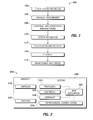
- embodiments of the disclosure may be described in the context of an exemplary aircraft manufacturing and service method 100 (method 100) as shown in Figure 1 and an aircraft 200 as shown in Figure 2 .
- the method 100 may comprise specification and design 104 of the aircraft 200, and material procurement 106.
- component and subassembly manufacturing 108 (process 108) and system integration 110 of the aircraft 200 takes place.
- the aircraft 200 may go through certification and delivery 112 in order to be placed in service 114.
- routine maintenance and service 116 which may also comprise modification, reconfiguration, refurbishment, and so on).
- a system integrator may comprise, for example but without limitation, any number of aircraft manufacturers and major-system subcontractors
- a third party may comprise, for example but without limitation, any number of vendors, subcontractors, and suppliers
- an operator may comprise, for example but without limitation, an airline, leasing company, military entity, service organization; and the like.
- the aircraft 200 produced by the method 100 may comprise an airframe 218 with a plurality of systems 220 and an interior 222.
- high-level systems of the systems 220 comprise one or more of a propulsion system 224, an electrical system 226, a hydraulic system 228, an environmental control system 230, and one or more heat exchanger systems 232.
- the one or more heat exchanger systems 232 may be contained in the airframe 218, the interior 222, the systems 220 such as the propulsion system 224, the electrical system 226, the hydraulic system 228, and the environmental control system 230 or any system of the aircraft 200. Any number of other systems may also be included.
- an aerospace example is shown, the embodiments of the disclosure may be applied to other industries.
- an airplane comprises a single, thermal management or, heat exchanger system that manages waste heat from multiple systems. Rather, each system generally comprises one or more heat exchangers to manage waste heat produced by its components.
- Apparatus and methods embodied herein may be employed during any one or more of the stages of the method 100.
- components or subassemblies corresponding to production of the process 108 may be fabricated or manufactured in a manner similar to components or subassemblies produced while the aircraft 200 is in service.
- one or more apparatus embodiments, method embodiments, or a combination thereof may be utilized during production stages of the process 108 and the system integration 110, for example, by substantially expediting assembly of or reducing the cost of an aircraft 200.
- one or more of apparatus embodiments, method embodiments, or a combination thereof may be utilized while the aircraft 200 is in service, for example and without limitation, to maintenance and service 116.
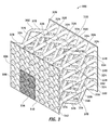
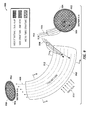
- FIG 3 is an illustration of an exemplary micro-lattice cross-flow heat exchanger 300 according to an embodiment of the disclosure.
- the micro-lattice cross-flow heat exchanger 300 may comprise a structural body 320, a manifold 306/322, and a plurality of hollow nodes 302/314.
- the structural body 320 comprises a plurality of hollow channels 304/316 configured to flow a first fluid 522 ( Figure 5 ) within the hollow channels 304/316 and a second fluid 502 ( Figure 5 ) external to the hollow channels 304/316.
- the hollow channels 304/316 may be a polymer micro-truss structure in a form of a regular hollow three-dimensional micro-truss of intersecting tubes, configured with hollow nodes 302/314 at the intersections of the hollow channels 304/316, so that an interior of each of the hollow channels 304/316 is in communication with any other hollow channels 304/316 it intersects.
- the hollow channels 304/316 comprise hollow truss elements within a hollow three-dimensional micro-truss comprising: first hollow truss elements 324 extending along a first direction 330, second truss hollow truss elements 326 extending along a second direction 332, third truss hollow truss elements 328 extending along a third direction 334.
- the hollow channels 304/316 may comprise, for example but without limitation, a cross-sectional shape that can be elliptical, circular, square, triangular, octagonal, star-shaped, a combination thereof, or other shape. Large aspect ratio elliptical shapes may improve heat transfer, and orientation of an ellipse's major axis may enhance heat transfer and enable better control of a pressure drop incurred by flow of the second fluid.
- the hollow channels 304/316 may comprise, for example but without limitation, one or more heat pipes 800 ( Figure 8 ).
- Access to an interior fluid volume, formed by connected interiors of the hollow channels 304/316, may be provided by an architected fluid interface, which may also be referred to as a manifold such as the manifold 306/322, at each end of the structural body 320.
- a manifold such as the manifold 306/322
- the manifold 306/322 is coupled to a first surface 512 and a second surface 518 ( Figure 5 ) of the structural body 320 respectively.
- the manifold 306/322 each comprises a plurality of openings 308/310 into the hollow channels 304/316.
- a cross section (e.g., lateral, longitudinal, or other cross section) of each of the openings 308/310 may comprise, for example but without limitation, a tapered shape (e.g., for a longitudinal cross section), a polygon shape, quadrilateral shape, a cross-section of a hollow pyramid (e.g., for a lateral or longitudinal cross section), or other cross section configuration.
- the openings 308/310 can be protruding or square-edged, or to reduce pressure drop incurred by the first flow, the openings can be radiused or tapered.
- the manifold 306/322 may comprise a particulate filter 336.
- the particulate filter 336 may be used to decrease a head loss coefficient of a flow encountering the openings 308/310.
- Each of the hollow channels 304/316 that is at a surface such as the first surface 512 or the second surface 518 where a manifold 306/322 is placed comprises an opening such as the openings 308/310, but some tube segments of the hollow channels 304/316 may connect two nodes instead of one node and one opening or, as illustrated in Figure 3 , into groups of hollow channels 304/316.
- the openings 308/310 may be in a form of a funnel or hollow pyramid, with a depth approximately or substantially equal to one half of the length, in a direction of a bore of the funnel, of a unit cell of the hollow three-dimensional micro-truss of hollow channels 304/316.
- Smooth transitions using the openings 308/310 shaped as described above (e.g., tapered etc.), at an interface between a bulk fluid and a hollow porous material such as the hollow channels 304/316 may result in significantly lower pressure drop for a fluid flowing into the hollow channels 304/316 and higher pressure recovery for a fluid exiting from the hollow channels 304/316 than manifolds having a flat surface with a flush hole for each hollow channels 304/316.
- a head loss coefficient of a flow encountering a right-angle inlet is approximately 0.5, while the head loss coefficient for a filleted inlet is as low as 0.04, representing an improvement of 12.5 times.
- the hollow nodes 302/314 comprise locations at which the hollow channels 304/316 interpenetrate.
- Figure 4 is an illustration of an expanded view 400 of an exemplary micro-lattice cross-flow heat exchanger 300 showing hollow channels entering and leaving hollow nodes according to an embodiment of the disclosure.
- hollow nodes 404, 406, 420, 434 and 446 comprise various configurations for flow of a fluid in the direction 402.
- Hollow node 404 is interpenetrated by hollow truss elements 410, 414 and 418 bringing fluid into the hollow node 404, and by hollow truss elements 448, 452 and 456 receiving fluid from the hollow node 404.
- Hollow node 406 is interpenetrated by hollow truss elements 408, 412 and 424 bringing fluid into the hollow node 406, and by hollow elements 454, 458 and 460 receiving fluid from the hollow node 406.
- Hollow node 420 is interpenetrated by hollow truss elements (not shown) bringing fluid into the hollow node 420, and by hollow truss elements 408, 418, 422 and 432 receiving fluid from the hollow node 420.
- Hollow node 434 is interpenetrated by hollow truss elements 422, 426 and 430 bringing fluid into the hollow node 434, and by hollow truss elements 440, 442 and 444 receiving fluid from the hollow node 434.
- Node 446 is interpenetrated by hollow truss elements 438, 444, 448 and 458 bringing fluid into the hollow node 446, and by hollow elements (not shown) receiving fluid from the hollow node 446.
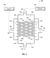
- FIG. 5 is an illustration of an exemplary schematic of a micro-lattice cross-flow heat exchanger 500 according to an embodiment of the disclosure.
- the micro-lattice cross-flow heat exchanger 500 may comprise a structural body 514 (320 in Figure 3 ), a first input manifold 524, a first output manifold 534, a second input manifold 508, and a second output manifold 526.
- the first fluid 522 is flowed into the first input manifold 524 coupled to a surface 512 of the structural body 514.
- the structural body 514 is configured for the first fluid 522 to flow into and within a plurality of hollow channels 546/544 (302/314 in Figure 3 ).
- the structural body 514 comprises a plurality of hollow nodes 516/530 (302/314 in Figure 3 ) at which the hollow channels 546/544 interpenetrate.
- the first input manifold 524 and the first output manifold 534 comprise a plurality of openings 308/310 (see Figure 3 ) into the hollow channels 546/544.
- the first fluid 522 transfers heat to/from the structural body 514 and exits the first output manifold 534 as a first heat changed fluid 536.
- the second fluid 502 is flowed into the second input manifold 508 around and external to the hollow channels 546/544.
- the second fluid 502 transfers heat from/to the structural body 514 and exits the second output manifold 526 as a second heat changed fluid 540. Thereby, heat is transferred between the first fluid 522 and the second fluid 502 via the structural body 514.
- a first aircraft fluid source inlet 548 is configured to provide a first fluid 522 from a first aircraft system 552.
- a second aircraft fluid source inlet 504 is configured to provide a second fluid 502 from a second aircraft system 554.
- the structural body 320/514 is configured to support aviation induced structural loads and exchange heat between the first fluid 522 and the second fluid 502.
- the aviation induced structural loads may comprise, for example but without limitation, a proof and burst load, an air pressure cycling load, a vibration load, an inertial load, a thermal cycling load, an airframe structural support load, a wing fairing bending load, a combination thereof, an/or other aviation structural load.
- the structural body 320/514 comprises a plurality of the hollow channels 546/544 forming two interpenetrating fluidically isolated volumes and configured for flow of the first fluid 522 within the hollow channels 546/544 and flow of the second fluid 502 external to the hollow channels 546/544 isolated from the first fluid 522.
- the hollow channels 546/544 comprise a hollow three-dimensional micro-truss such as the micro-lattice cross-flow heat exchanger 300/500 comprising hollow truss elements extending along at least three directions, and a plurality of hollow nodes interpenetrated by the hollow truss elements as explained above.
- the micro-lattice cross-flow heat exchanger 300/500 may be used in, for example but without limitation, an aircraft nitrogen enriched air cooler, a power electronics cooler, a precooler, an air conditioning pack heat exchanger, an oil cooler, a refrigeration condenser, an evaporator exchanging heat between hot and cold refrigerant and air, a hydraulic fluid heat exchanger exchanging heat between hydraulic fluid and fuel or ram air, a liquid cooling system heat exchanger which exchanges heat between liquid coolant and ram air, and other heat exchange application.
- the first fluid 522 and the second fluid 502 may comprise, for example but without limitation, an aircraft engine bleed air, an aircraft RAM ambient air, an aircraft nitrogen enriched air cooler, a recycled aircraft cabin air, a fanned heated air from a heat generating component on an aircraft, a pumped aircraft engine oil, a pumped aircraft hydraulic oil, a pumped aircraft gearbox oil, a pumped aircraft liquid coolant, a pumped aircraft refrigerant fluid, a vaporized fluid from a heat pipe, and other fluidic source.
- the micro-lattice cross-flow heat exchanger 500 may use engine bleed air as one fluid (first fluid) and engine fan air as the other fluid (second fluid). This embodiment may be used as a pre-cooler for an aircraft cabin air conditioning and temperature control system.
- the micro-lattice cross-flow heat exchanger 500 may use compressed air (e.g., engine bleed air) as one fluid (first fluid) and ambient (ram) air as the other fluid (second fluid).
- compressed air e.g., engine bleed air
- ram ambient air
- the micro-lattice cross-flow heat exchanger 500 may use compressed air (e.g., engine bleed air) as one fluid (first fluid) and refrigerant as the other fluid (second fluid).
- compressed air e.g., engine bleed air
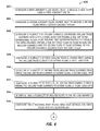
- FIG. 6 is an illustration of an exemplary flowchart showing a process 600 for configuring a micro-lattice cross-flow heat exchanger for an aircraft according to an embodiment of the disclosure.
- the various tasks performed in connection with process 600 may be performed mechanically, by software, hardware, firmware, or any combination thereof.
- the following description of process 600 may refer to elements mentioned above in connection with Figures 1-5 .
- portions of the process 600 may be performed by different elements of the micro-lattice cross-flow heat exchanger 300/500 such as the structural body 320/514, the manifold 306/322, the hollow channels 304/316, the hollow nodes 302/314, the first aircraft system 552, the second aircraft system 554, etc.
- Process 600 may have functions, material, and structures that are similar to the embodiments shown in Figures 1-4 . Therefore common features, functions, and elements may not be redundantly described here.
- Process 600 may begin by configuring a first aircraft fluid source inlet to receive a first fluid from a first aircraft system (task 602).
- Process 600 may continue by configuring a second aircraft fluid source inlet to receive a second fluid from a second aircraft system (task 604).
- Process 600 may continue by configuring a plurality of hollow channels comprising hollow truss elements into a structural body comprising a hollow three-dimensional micro-truss forming two interpenetrating fluidically isolated volumes operable for the first fluid to flow within the hollow channels and the second fluid to flow external to the hollow channels isolated from the first fluid (task 606).
- Process 600 may continue by configuring a plurality of first hollow truss elements from among the hollow truss elements to extend along a first direction (task 608).
- Process 600 may continue by configuring a plurality of second truss hollow truss elements from among the hollow truss elements to extend along a second direction (task 610).
- Process 600 may continue by configuring a plurality of third truss hollow truss elements from among the hollow truss elements to extend along a third direction (task 612).
- Process 600 may continue by interpenetrating a plurality of hollow nodes by the hollow channels (task 614).
- Process 600 may continue by configuring the structural body to exchange heat between the first fluid and the second fluid (task 616).
- Process 600 may continue by configuring the structural body to support aviation induced structural loads (task 618).
- Process 600 may continue by coupling a first manifold comprising a plurality of first openings to the first aircraft fluid source inlet and a first surface of the structural body (task 620).
- Process 600 may continue by coupling the first openings to the hollow channels (task 622).
- Process 600 may continue by coupling a second manifold comprising a plurality of second openings to the second aircraft fluid source inlet and a second surface of the structural body (task 624).
- Process 600 may continue by coupling the second openings to the hollow channels (task 626).
- Process 600 may continue by configuring a cross section (e.g., lateral, longitudinal, or other cross section) of each of the openings to comprise a tapered opening, a polygon, a quadrilateral, a cross section of a hollow pyramid, or a combination thereof (task 628).
- a cross section e.g., lateral, longitudinal, or other cross section
- a process of forming a hollow porous material such as the hollow channels 304/316 into the structural body 320 is described in U.S. patent 7,653,276 .
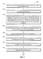
- FIG. 7 is an illustration of an exemplary flowchart showing a process for operating a micro-lattice cross-flow heat exchanger for an aircraft according to an embodiment of the disclosure.
- the various tasks performed in connection with process 700 may be performed mechanically, by software, hardware, firmware, or any combination thereof.
- the following description of process 700 may refer to elements mentioned above in connection with Figures 1-4 .
- portions of the process 700 may be performed by different elements of the micro-lattice cross-flow heat exchanger 300/400 such as the structural body 320/514, the manifold 306/322, the hollow channels 304/316, the hollow nodes 302/314, the first aircraft system 552, the second aircraft system 554, etc.
- Process 700 may have functions, material, and structures that are similar to the embodiments shown in Figures 1-4 . Therefore common features, functions, and elements may not be redundantly described here.
- Process 700 may begin by receiving a first fluid in a first aircraft fluid source inlet from a first aircraft system (task 702).
- Process 700 may continue receiving a second fluid in a second aircraft fluid source inlet from a second aircraft system (task 704).
- Process 700 may continue by supporting an aviation structural load on a structural body forming two interpenetrating fluidically isolated volumes and comprising a plurality of hollow channels comprising a hollow three-dimensional micro-truss comprising a plurality of hollow truss elements extending along at least three directions, and a plurality of hollow nodes interpenetrated by the hollow truss elements (task 706).
- Process 700 may continue by flowing the first fluid from the first aircraft fluid source inlet into the hollow channels through a first manifold comprising a plurality of first openings into the hollow channels (task 708).
- Process 700 may continue by flowing the first fluid within the hollow channels (task 710).
- Process 700 may continue by flowing the first fluid out of a second manifold comprising a plurality of second openings from the hollow channels (task 712).
- Process 700 may continue by flowing the second fluid from the second aircraft fluid source inlet external to the hollow channels (task 714).
- Process 700 may continue by transferring heat between the first fluid flow and the second fluid flow via the structural body (task 716).
- Process 700 may continue by inducing the first fluid flow from engine bleed air and the second fluid flow from engine fan air (task 718).
- Process 700 may continue by using the micro-lattice cross-flow heat exchanger in an aircraft cabin air conditioning and temperature control system, wherein the aviation structural load comprises a wing fairing bending load (task 720).
- Process 700 may continue by inducing the first fluid flow from engine bleed air and the second fluid flow from ram air (task 722).
- Process 700 may continue by using the micro-lattice cross-flow heat exchanger in an aircraft cabin air conditioning and temperature control system, wherein the aviation structural load comprises a wing fairing bending load (task 724).
- Process 700 may continue by inducing the first fluid flow from engine bleed air, wherein the second fluid flow comprises a refrigerant (task 726).
- the refrigerant may comprise, for example but without limitation, FREON ®, FREON ® replacements (e.g., R134a), water, chlorofluorocarbons, ram air, fan air, or other refrigerant.
- Process 700 may continue by using the micro-lattice cross-flow heat exchanger in an aircraft cabin air conditioning and temperature control system, wherein the aviation structural load comprises a proof and burst load, and a pressure cycle load (task 728).
- the aviation structural load comprises a proof and burst load, and a pressure cycle load (task 728).
- Process 700 may continue by inducing the first fluid flow from engine oil, wherein the second fluid flow comprises fan air (task 730).
- Process 700 may continue by using the micro-lattice cross-flow heat exchanger in an oil cooling system, wherein the aviation structural load comprises a proof and burst load, a pressure cycle load, and a vibration load (task 732).
- the aviation structural load comprises a proof and burst load, a pressure cycle load, and a vibration load (task 732).
- Process 700 may continue by inducing the first fluid flow from hydraulic fluid, wherein the second fluid flow comprises fuel or ram air (task 734).
- Process 700 may continue by using the micro-lattice cross-flow heat exchanger in an oil cooling system, wherein the aviation structural load comprises a proof and burst load, a pressure cycle load, and a vibration load (task 736).
- the aviation structural load comprises a proof and burst load, a pressure cycle load, and a vibration load (task 736).
- Process 700 may continue by inducing the first fluid flow and the second fluid flow from an aircraft engine bleed air, an aircraft RAM ambient air, an aircraft nitrogen enriched air cooler, a recycled aircraft cabin air, a fanned heated air from a heat generating component on an aircraft, a pumped aircraft engine oil, a pumped aircraft hydraulic fluid, a pumped aircraft gearbox oil, a pumped aircraft liquid coolant, and a pumped aircraft refrigerant fluid, or a combination thereof (task 738).
- Process 700 may continue by using the micro-lattice cross-flow heat exchanger in an aircraft nitrogen enriched air cooler, a power electronics cooler, a precooler, an air conditioning pack heat exchanger, an oil cooler, a refrigeration condenser, an evaporator exchanging heat between hot and cold refrigerant and air, a hydraulic fluid heat exchanger exchanging heat between hydraulic fluid and fuel or ram air, a liquid cooling system heat exchanger which exchanges heat between liquid coolant and ram air, or a combination thereof (task 740).
- FIG 8 is an illustration of an end view 806, a section A-A view 802, and a section B-B view 804 of an exemplary schematic of a micro-lattice cross-flow heat exchanger 800 (heat pipe 800) according to an embodiment of the disclosure.
- the micro-lattice cross-flow heat exchanger 800 comprises a heat pipe configuration, thus the micro-lattice cross-flow heat exchanger 800 and the heat pipe 800 may be used interchangeably in this document.
- the micro-lattice cross-flow heat exchanger 800 may comprise a micro-truss structural body 812 (320/514 in Figures 3 and 5 ) comprising the hollow channels 304/316/546/544 ( Figures 3 and 5 ).
- the heat pipe 800 may comprise, for example, a 2-sided heat pipe interconnected by the micro-truss structural body 812.
- the micro-truss structural body 812 functions as a condenser for a heat pipe fluid (not shown) within the micro-truss structural body 812 that is vaporized at sides 828/830 that are exposed to a heat load(flux) 832/834 respectively.
- the heat pipe fluid of the heat pipe 800 may comprise, for example but without limitation, water, Freon, a hydrocarbon, an ionic liquid, or other fluid.
- Each side 824/826/828/830 of the micro-lattice cross-flow heat exchanger 800 comprises a wick structure 816/818/820/822 respectively.
- the wick structure 816/818/820/822 may be configured on a subset of the sides 824/826/828/830 such as, but without limitation, all of the sides 824/826/828/830, three sides among the sides 824/826/828/830, a single side among the sides 824/826/828/830, or other configuration.
- a laterally oriented wick structure in all adjacent four of the sides 824/826/828/830 provide return paths of condensed fluid back to a hot spot on one or more of the sides 824/826/828/830.
- the wick structure 816/818/820/822 may comprise, for example but without limitation, a longitudinally oriented wick structure, a laterally oriented wick structure, an omni-directionally oriented wick structure, or other wick structure.
- a cooling fluid 808 enters a first side 836 of the micro-lattice cross-flow heat exchanger 800 and flows through and around an exterior 814 of the micro-truss structural body 812.
- the cooling fluid 808 may exit a second side 838 of the micro-lattice cross-flow heat exchanger 800.
- Heat applied to any area of the sides 824/826/828/830 of the micro-lattice cross-flow heat exchanger 800 results in the heat pipe fluid evaporating from point(s) of exposure and a vapor of the heat pipe fluid migrating into the hollow channels 304/316 ( Figure 3 ) of the micro-truss structural body 812 in closest proximity to the point(s) of exposure.
- a flow of the cooling fluid 808 through and around the exterior 814 of the micro-truss structural body 812 then absorbs heat from the vapor of the heat pipe fluid and causes it to condense to a condensed refrigerant.
- the condensed refrigerant flows through the micro-truss structural body 812 (e.g., guided by gravity) to the wick structure 816/818/820/822 in a lowest of the sides 824/826/828/830. Capillary action in the wick structure 816/818/820/822 then guides the condensed refrigerant back to the hot spot, where the cycle begins again.
- the first aircraft system 552 comprises a heat pipe surface (not shown) operable to vaporize the heat pipe fluid in response to heating of the heat pipe surface to provide the vaporized heat pipe fluid.
- FIG. 9 is an illustration of an end view, a section A-A view, and a section B-B view of an exemplary schematic of a micro-lattice cross-flow heat exchanger 900 comprising a heat pipe configuration according to an embodiment of the disclosure.
- the micro-lattice cross-flow heat exchanger 900 may comprise various cross-section shape configurations of a flow body 912 such as, but without limitation, circles, ellipses, triangles, pentagons, polygons, variable cross-sections along their lengths, or a combination thereof.
- a surface 916 of the micro-lattice cross-flow heat exchanger 900 absorbs a heat flux 914.
- the micro-lattice cross-flow heat exchanger 900 comprises longitudinal and lateral wick structures 904, and a hollow micro-truss structure 902 occupies a center of the micro-lattice cross-flow heat exchanger 900.
- a cooling fluid 908 enters the micro-lattice cross-flow heat exchanger 900 through a coolant inlet 906 and flows through and around an exterior of the hollow micro-truss structure 902.
- the cooling fluid 908 absorbs heat from the hollow micro-truss structure 902 and a vaporized heat pipe fluid (not shown).
- the hollow micro-truss structure 902 serves as a condenser to condense the vaporized heat pipe fluid into a condensed refrigerant (not shown).
- the wick structures 904 transport the condensed refrigerant from the hollow micro-truss structure 902 back to the wick structures 904 and back to a heated area, thereby enabling continuous evaporation and, in effect, management of a heat load.
- embodiments of the disclosure provide a cost-effective fluid flow interface to a hollow porous material, which reduces discontinuities and sharp edges and consequently reduces flow disruption, reduces pressure drop for fluid flowing into the hollow porous material, and/or increases pressure recovery for fluid exiting the hollow porous material.
- a group of items linked with the conjunction "and” should not be read as requiring that each and every one of those items be present in the grouping, but rather should be read as “and/or” unless expressly stated otherwise.
- a group of items linked with the conjunction "or” should not be read as requiring mutual exclusivity among that group, but rather should also be read as “and/or” unless expressly stated otherwise.
Landscapes
- Engineering & Computer Science (AREA)
- Physics & Mathematics (AREA)
- Thermal Sciences (AREA)
- Mechanical Engineering (AREA)
- General Engineering & Computer Science (AREA)
- Life Sciences & Earth Sciences (AREA)
- Sustainable Development (AREA)
- Heat-Exchange Devices With Radiators And Conduit Assemblies (AREA)
Abstract
Description
- Embodiments of the present disclosure relate generally to heat exchangers. More particularly, embodiments of the present disclosure relate to aircraft heat exchangers.
- Heat exchangers are used in various thermal management applications such as heating, refrigeration, air conditioning, and in systems which create waste heat such as power stations, chemical plants, and petroleum refineries, and in conglomerations of systems, such as aircraft. A heat exchanger generally transfers heat from one medium to another. The media may be separated to never mix or may be in direct contact. Interface pressure loss may represent a significant component consideration. Generally the rate of heat transfer is proportional to the heat exchanger size. Ongoing research is in part focused on development of efficient heat exchanger systems that are light and small in size.
- An aircraft micro-lattice cross-flow heat exchanger and methods are presented. A first aircraft fluid source inlet provides a first fluid from a first aircraft system, and a second aircraft fluid source inlet provides a second fluid from a second aircraft system. A structural body supports aviation induced structural loads and exchanges heat between the first fluid and the second fluid. The structural body comprises hollow channels forming two interpenetrating fluidically isolated volumes that flow the first fluid within the hollow channels and flow the second fluid external to the hollow channels isolated from the first fluid. The hollow channels comprise a hollow three-dimensional micro-truss comprising hollow truss elements extending along at least three directions, and hollow nodes interpenetrated by the hollow truss elements.
- In this manner, embodiments of the disclosure provide a heat exchanger that also bears structural loads such as system pressures. The heat exchanger comprises enclosed fluid flow interfaces to a hollow porous material that reduce discontinuities and sharp edges and consequently reduce flow disruptions, reduce pressure drops for fluid flowing into the hollow porous material, and/or increases pressure recovery for fluid exiting the hollow porous material.
- In an embodiment, a method for operating a micro-lattice cross-flow heat exchanger for an aircraft receives a first fluid in a first aircraft fluid source inlet from a first aircraft system, and receives a second fluid in a second aircraft fluid source inlet from a second aircraft system. The method further supports an aviation structural load on a structural body forming two interpenetrating fluidically isolated volumes and comprising hollow channels comprising hollow truss elements within a hollow three-dimensional micro-truss. The hollow three-dimensional micro-truss comprises hollow truss elements extending along at least three directions, and a plurality of hollow nodes interpenetrated by the hollow truss elements. The method further flows the first fluid from the first aircraft fluid source inlet into the hollow channels through a first manifold comprising first openings into the hollow channels. The method further flows the first fluid within the hollow channels, and flows the first fluid out of a second manifold comprising second openings from the hollow channels. The method further flows the second fluid external to the hollow channels and transfers heat between the first fluid flow and the second fluid flow via the structural body.
- In another embodiment, a micro-lattice cross-flow heat exchanger for an aircraft comprises a first aircraft fluid source inlet, a second aircraft fluid source inlet, and a structural body. The first aircraft fluid source inlet provides a first fluid from a first aircraft system, and the second aircraft fluid source inlet provides a second fluid from a second aircraft system. The structural body supports aviation induced structural loads and exchanges heat between the first fluid and the second fluid. The structural body comprises hollow channels that form two interpenetrating fluidically isolated volumes configured to flow the first fluid within the hollow channels and flow the second fluid external to the hollow channels and isolated from the first fluid. The hollow channels comprising a hollow three-dimensional micro-truss. The hollow three-dimensional micro-truss comprises hollow truss elements extending along at least three directions, and hollow nodes interpenetrated by the hollow truss elements.
- In a further embodiment, a method for configuring a micro-lattice cross-flow heat exchanger for an aircraft configures a first aircraft fluid source inlet to receive a first fluid from a first aircraft system. The method further configures a second aircraft fluid source inlet to receive a second fluid from a second aircraft system. The method further configures hollow channels comprising hollow truss elements into a structural body comprising a hollow three-dimensional micro-truss forming two interpenetrating fluidically isolated volumes operable for the first fluid to flow within the hollow channels and the second fluid to flow external to the hollow channels isolated from the first fluid. The method further configures first hollow truss elements from among the hollow truss elements to extend along a first direction, and configures second hollow truss elements from among the hollow truss elements to extend along a second direction. The method further configures third hollow truss elements from among the hollow truss elements to extend along a third direction, and interpenetrates hollow nodes by the hollow truss elements. The method further configures the structural body to exchange heat between the first fluid and the second fluid, and configures the structural body to support aviation induced structural loads.
- This summary is provided to introduce a selection of concepts in a simplified form that are further described below in the detailed description. This summary is not intended to identify key features or essential features of the claimed subject matter, nor is it intended to be used as an aid in determining the scope of the claimed subject matter.
- A more complete understanding of embodiments of the present disclosure may be derived by referring to the detailed description and claims when considered in conjunction with the following figures, wherein like reference numbers refer to similar elements throughout the figures. The figures are provided to facilitate understanding of the disclosure without limiting the breadth, scope, scale, or applicability of the disclosure. The drawings are not necessarily made to scale.
-
Figure 1 is an illustration of a flow diagram of an exemplary aircraft production and service methodology. -
Figure 2 is an illustration of an exemplary block diagram of an aircraft. -
Figure 3 is an illustration of an exemplary micro-lattice cross-flow heat exchanger according to an embodiment of the disclosure. -
Figure 4 is an illustration of an expanded view of an exemplary micro-lattice cross-flow heat exchanger showing hollow channels entering and leaving hollow nodes according to an embodiment of the disclosure. -
Figure 5 is an illustration of an exemplary schematic of a micro-lattice cross-flow heat exchanger according to an embodiment of the disclosure. -
Figure 6 is an illustration of an exemplary flowchart showing a process for configuring micro-lattice cross-flow heat exchanger for an aircraft according to an embodiment of the disclosure. -
Figure 7 is an illustration of an exemplary flowchart showing a process for operating a micro-lattice cross-flow heat exchanger for an aircraft according to an embodiment of the disclosure. -
Figure 8 is an illustration of an exemplary schematic of a micro-lattice cross-flow heat exchanger comprising a heat pipe according to an embodiment of the disclosure. -
Figure 9 is an illustration of an exemplary schematic of a micro-lattice cross-flow heat exchanger comprising a heat pipe according to an embodiment of the disclosure. - The following detailed description is exemplary in nature and is not intended to limit the disclosure or the application and uses of the embodiments of the disclosure. Descriptions of specific devices, techniques, and applications are provided only as examples. Modifications to the examples described herein will be readily apparent to those of ordinary skill in the art, and the general principles defined herein may be applied to other examples and applications without departing from the spirit and scope of the disclosure. Furthermore, there is no intention to be bound by any expressed or implied theory presented in the preceding field, background, summary or the following detailed description. The present disclosure should be accorded scope consistent with the claims, and not limited to the examples described and shown herein.
- Embodiments of the disclosure may be described herein in terms of functional and/or logical block components and various processing steps. It should be appreciated that such block components may be realized by any number of hardware, software, and/or firmware components configured to perform the specified functions. For the sake of brevity, conventional techniques and components related to aircraft, aircraft components, heat exchangers, fluid dynamics, and other functional aspects of the systems (and the individual operating components of the systems) may not be described in detail herein. In addition, those skilled in the art will appreciate that embodiments of the present disclosure may be practiced in conjunction with a variety of structural bodies, and that the embodiments described herein are merely example embodiments of the disclosure.
- Embodiments of the disclosure are described herein in the context of some non-limiting applications, namely, an air conditioning heat exchanger. Embodiments of the disclosure, however, are not limited to such air conditioning applications, and the techniques described herein may also be utilized in other applications. For example, embodiments may be applicable to electronics cooling, battery cooling, liquid-liquid heat exchange, gas-liquid heat exchange, slurry-liquid heat exchange (e.g., slush hydrogen to liquid nitrogen), slurry-gas heat exchange, fuel-coolant heat exchange, Synergistic Air-Breathing Rocket Engines (SABRE), engine precoolers, engine oil coolers, hypersonic precoolers, intercoolers, hydraulic fluid heat exchangers, refrigeration heat exchangers, or other heat exchange applications.
- As would be apparent to one of ordinary skill in the art after reading this description, the following are examples and embodiments of the disclosure and are not limited to operating in accordance with these examples. Other embodiments may be utilized and structural changes may be made without departing from the scope of the exemplary embodiments of the present disclosure.
- Embodiments provide a lightweight, high-performance cross-flow micro-lattice heat exchanger structure for an aircraft, including air to air, liquid to liquid, and liquid to air heat transfer in both single and two-phase flow. Embodiments use a hollow micro-lattice structure as a core structure in the micro-lattice heat exchanger structure for particular applications. A fluid stream is passed through hollow tubes comprising the hollow micro-lattice structure. Another fluid stream passes around the hollow micro-lattice structure. This fluid passage mechanism permits transfer of heat between the two fluid streams without mixing the two fluids. The hollow micro-lattice structure is well-suited for use in multiple places on an aircraft where high heat transfer between two fluid streams, low fluid pressure drop, low mass and low volume is desirable. For example, the micro-lattice heat-exchanger structure may be used to transfer heat from compressed air stream to a RAM air stream, thus providing a source of cabin air at the proper temperature and pressure for passenger comfort.
- Referring more particularly to the drawings, embodiments of the disclosure may be described in the context of an exemplary aircraft manufacturing and service method 100 (method 100) as shown in
Figure 1 and anaircraft 200 as shown inFigure 2 . During pre-production, themethod 100 may comprise specification anddesign 104 of theaircraft 200, andmaterial procurement 106. During production, component and subassembly manufacturing 108 (process 108) andsystem integration 110 of theaircraft 200 takes place. Thereafter, theaircraft 200 may go through certification anddelivery 112 in order to be placed inservice 114. While in service by a customer, theaircraft 200 is scheduled for routine maintenance and service 116 (which may also comprise modification, reconfiguration, refurbishment, and so on). - Each of the processes of
method 100 may be performed or carried out by a system integrator, a third party, and/or an operator (e.g., a customer). For the purposes of this description, a system integrator may comprise, for example but without limitation, any number of aircraft manufacturers and major-system subcontractors; a third party may comprise, for example but without limitation, any number of vendors, subcontractors, and suppliers; and an operator may comprise, for example but without limitation, an airline, leasing company, military entity, service organization; and the like. - As shown in
Figure 2 , theaircraft 200 produced by themethod 100 may comprise anairframe 218 with a plurality ofsystems 220 and an interior 222. Examples of high-level systems of thesystems 220 comprise one or more of apropulsion system 224, anelectrical system 226, ahydraulic system 228, anenvironmental control system 230, and one or moreheat exchanger systems 232. The one or moreheat exchanger systems 232 may be contained in theairframe 218, the interior 222, thesystems 220 such as thepropulsion system 224, theelectrical system 226, thehydraulic system 228, and theenvironmental control system 230 or any system of theaircraft 200. Any number of other systems may also be included. Although an aerospace example is shown, the embodiments of the disclosure may be applied to other industries. - It should not be inferred from
Figure 2 that an airplane comprises a single, thermal management or, heat exchanger system that manages waste heat from multiple systems. Rather, each system generally comprises one or more heat exchangers to manage waste heat produced by its components. - Apparatus and methods embodied herein may be employed during any one or more of the stages of the
method 100. For example, components or subassemblies corresponding to production of theprocess 108 may be fabricated or manufactured in a manner similar to components or subassemblies produced while theaircraft 200 is in service. In addition, one or more apparatus embodiments, method embodiments, or a combination thereof may be utilized during production stages of theprocess 108 and thesystem integration 110, for example, by substantially expediting assembly of or reducing the cost of anaircraft 200. Similarly, one or more of apparatus embodiments, method embodiments, or a combination thereof may be utilized while theaircraft 200 is in service, for example and without limitation, to maintenance andservice 116. -
Figure 3 is an illustration of an exemplary micro-latticecross-flow heat exchanger 300 according to an embodiment of the disclosure. The micro-latticecross-flow heat exchanger 300 may comprise astructural body 320, a manifold 306/322, and a plurality ofhollow nodes 302/314. - The
structural body 320 comprises a plurality ofhollow channels 304/316 configured to flow a first fluid 522 (Figure 5 ) within thehollow channels 304/316 and a second fluid 502 (Figure 5 ) external to thehollow channels 304/316. - In one embodiment, the
hollow channels 304/316 may be a polymer micro-truss structure in a form of a regular hollow three-dimensional micro-truss of intersecting tubes, configured withhollow nodes 302/314 at the intersections of thehollow channels 304/316, so that an interior of each of thehollow channels 304/316 is in communication with any otherhollow channels 304/316 it intersects. Thehollow channels 304/316 comprise hollow truss elements within a hollow three-dimensional micro-truss comprising: firsthollow truss elements 324 extending along afirst direction 330, second trusshollow truss elements 326 extending along asecond direction 332, third trusshollow truss elements 328 extending along athird direction 334. - The
hollow channels 304/316 may comprise, for example but without limitation, a cross-sectional shape that can be elliptical, circular, square, triangular, octagonal, star-shaped, a combination thereof, or other shape. Large aspect ratio elliptical shapes may improve heat transfer, and orientation of an ellipse's major axis may enhance heat transfer and enable better control of a pressure drop incurred by flow of the second fluid. In some embodiments, thehollow channels 304/316 may comprise, for example but without limitation, one or more heat pipes 800 (Figure 8 ). - Access to an interior fluid volume, formed by connected interiors of the
hollow channels 304/316, may be provided by an architected fluid interface, which may also be referred to as a manifold such as the manifold 306/322, at each end of thestructural body 320. - The manifold 306/322 is coupled to a
first surface 512 and a second surface 518 (Figure 5 ) of thestructural body 320 respectively. The manifold 306/322 each comprises a plurality ofopenings 308/310 into thehollow channels 304/316. A cross section (e.g., lateral, longitudinal, or other cross section) of each of theopenings 308/310 may comprise, for example but without limitation, a tapered shape (e.g., for a longitudinal cross section), a polygon shape, quadrilateral shape, a cross-section of a hollow pyramid (e.g., for a lateral or longitudinal cross section), or other cross section configuration. Theopenings 308/310 can be protruding or square-edged, or to reduce pressure drop incurred by the first flow, the openings can be radiused or tapered. The manifold 306/322 may comprise aparticulate filter 336. Theparticulate filter 336 may be used to decrease a head loss coefficient of a flow encountering theopenings 308/310. - Each of the
hollow channels 304/316 that is at a surface such as thefirst surface 512 or thesecond surface 518 where a manifold 306/322 is placed comprises an opening such as theopenings 308/310, but some tube segments of thehollow channels 304/316 may connect two nodes instead of one node and one opening or, as illustrated inFigure 3 , into groups ofhollow channels 304/316. In the embodiment illustrated inFigure 3 , theopenings 308/310 may be in a form of a funnel or hollow pyramid, with a depth approximately or substantially equal to one half of the length, in a direction of a bore of the funnel, of a unit cell of the hollow three-dimensional micro-truss ofhollow channels 304/316. - Smooth transitions using the
openings 308/310 shaped as described above (e.g., tapered etc.), at an interface between a bulk fluid and a hollow porous material such as thehollow channels 304/316 may result in significantly lower pressure drop for a fluid flowing into thehollow channels 304/316 and higher pressure recovery for a fluid exiting from thehollow channels 304/316 than manifolds having a flat surface with a flush hole for eachhollow channels 304/316. In particular, a head loss coefficient of a flow encountering a right-angle inlet is approximately 0.5, while the head loss coefficient for a filleted inlet is as low as 0.04, representing an improvement of 12.5 times. - The
hollow nodes 302/314 comprise locations at which thehollow channels 304/316 interpenetrate. -
Figure 4 is an illustration of an expandedview 400 of an exemplary micro-latticecross-flow heat exchanger 300 showing hollow channels entering and leaving hollow nodes according to an embodiment of the disclosure. For example but without limitation,hollow nodes direction 402.Hollow node 404 is interpenetrated byhollow truss elements hollow node 404, and byhollow truss elements hollow node 404.Hollow node 406 is interpenetrated byhollow truss elements hollow node 406, and byhollow elements hollow node 406.Hollow node 420 is interpenetrated by hollow truss elements (not shown) bringing fluid into thehollow node 420, and byhollow truss elements hollow node 420.Hollow node 434 is interpenetrated byhollow truss elements hollow node 434, and byhollow truss elements hollow node 434.Node 446 is interpenetrated byhollow truss elements hollow node 446, and by hollow elements (not shown) receiving fluid from thehollow node 446. -
Figure 5 is an illustration of an exemplary schematic of a micro-latticecross-flow heat exchanger 500 according to an embodiment of the disclosure. The micro-latticecross-flow heat exchanger 500 may comprise a structural body 514 (320 inFigure 3 ), afirst input manifold 524, afirst output manifold 534, asecond input manifold 508, and asecond output manifold 526. - The
first fluid 522 is flowed into thefirst input manifold 524 coupled to asurface 512 of thestructural body 514. Thestructural body 514 is configured for thefirst fluid 522 to flow into and within a plurality ofhollow channels 546/544 (302/314 inFigure 3 ). Thestructural body 514 comprises a plurality ofhollow nodes 516/530 (302/314 inFigure 3 ) at which thehollow channels 546/544 interpenetrate. Thefirst input manifold 524 and thefirst output manifold 534 comprise a plurality ofopenings 308/310 (seeFigure 3 ) into thehollow channels 546/544. Thefirst fluid 522 transfers heat to/from thestructural body 514 and exits thefirst output manifold 534 as a first heat changedfluid 536. - The
second fluid 502 is flowed into thesecond input manifold 508 around and external to thehollow channels 546/544. Thesecond fluid 502 transfers heat from/to thestructural body 514 and exits thesecond output manifold 526 as a second heat changedfluid 540. Thereby, heat is transferred between thefirst fluid 522 and thesecond fluid 502 via thestructural body 514. - In one embodiment, a first aircraft
fluid source inlet 548 is configured to provide afirst fluid 522 from afirst aircraft system 552. A second aircraftfluid source inlet 504 is configured to provide asecond fluid 502 from asecond aircraft system 554. Thestructural body 320/514 is configured to support aviation induced structural loads and exchange heat between thefirst fluid 522 and thesecond fluid 502. The aviation induced structural loads may comprise, for example but without limitation, a proof and burst load, an air pressure cycling load, a vibration load, an inertial load, a thermal cycling load, an airframe structural support load, a wing fairing bending load, a combination thereof, an/or other aviation structural load. - The
structural body 320/514 comprises a plurality of thehollow channels 546/544 forming two interpenetrating fluidically isolated volumes and configured for flow of thefirst fluid 522 within thehollow channels 546/544 and flow of thesecond fluid 502 external to thehollow channels 546/544 isolated from thefirst fluid 522. Thehollow channels 546/544 comprise a hollow three-dimensional micro-truss such as the micro-latticecross-flow heat exchanger 300/500 comprising hollow truss elements extending along at least three directions, and a plurality of hollow nodes interpenetrated by the hollow truss elements as explained above. - The micro-lattice
cross-flow heat exchanger 300/500 may be used in, for example but without limitation, an aircraft nitrogen enriched air cooler, a power electronics cooler, a precooler, an air conditioning pack heat exchanger, an oil cooler, a refrigeration condenser, an evaporator exchanging heat between hot and cold refrigerant and air, a hydraulic fluid heat exchanger exchanging heat between hydraulic fluid and fuel or ram air, a liquid cooling system heat exchanger which exchanges heat between liquid coolant and ram air, and other heat exchange application. - The
first fluid 522 and thesecond fluid 502 may comprise, for example but without limitation, an aircraft engine bleed air, an aircraft RAM ambient air, an aircraft nitrogen enriched air cooler, a recycled aircraft cabin air, a fanned heated air from a heat generating component on an aircraft, a pumped aircraft engine oil, a pumped aircraft hydraulic oil, a pumped aircraft gearbox oil, a pumped aircraft liquid coolant, a pumped aircraft refrigerant fluid, a vaporized fluid from a heat pipe, and other fluidic source. - In one embodiment, the micro-lattice
cross-flow heat exchanger 500 may use engine bleed air as one fluid (first fluid) and engine fan air as the other fluid (second fluid). This embodiment may be used as a pre-cooler for an aircraft cabin air conditioning and temperature control system. - In another embodiment, the micro-lattice
cross-flow heat exchanger 500 may use compressed air (e.g., engine bleed air) as one fluid (first fluid) and ambient (ram) air as the other fluid (second fluid). This embodiment may be used for the aircraft cabin air conditioning and temperature control system. - In a further embodiment, the micro-lattice
cross-flow heat exchanger 500 may use compressed air (e.g., engine bleed air) as one fluid (first fluid) and refrigerant as the other fluid (second fluid). This application is a subset of an air conditioning and temperature control system of the aircraft cabin. -
Figure 6 is an illustration of an exemplary flowchart showing aprocess 600 for configuring a micro-lattice cross-flow heat exchanger for an aircraft according to an embodiment of the disclosure. The various tasks performed in connection withprocess 600 may be performed mechanically, by software, hardware, firmware, or any combination thereof. For illustrative purposes, the following description ofprocess 600 may refer to elements mentioned above in connection withFigures 1-5 . In some embodiments, portions of theprocess 600 may be performed by different elements of the micro-latticecross-flow heat exchanger 300/500 such as thestructural body 320/514, the manifold 306/322, thehollow channels 304/316, thehollow nodes 302/314, thefirst aircraft system 552, thesecond aircraft system 554, etc.Process 600 may have functions, material, and structures that are similar to the embodiments shown inFigures 1-4 . Therefore common features, functions, and elements may not be redundantly described here. -
Process 600 may begin by configuring a first aircraft fluid source inlet to receive a first fluid from a first aircraft system (task 602). -
Process 600 may continue by configuring a second aircraft fluid source inlet to receive a second fluid from a second aircraft system (task 604). -
Process 600 may continue by configuring a plurality of hollow channels comprising hollow truss elements into a structural body comprising a hollow three-dimensional micro-truss forming two interpenetrating fluidically isolated volumes operable for the first fluid to flow within the hollow channels and the second fluid to flow external to the hollow channels isolated from the first fluid (task 606). -
Process 600 may continue by configuring a plurality of first hollow truss elements from among the hollow truss elements to extend along a first direction (task 608). -
Process 600 may continue by configuring a plurality of second truss hollow truss elements from among the hollow truss elements to extend along a second direction (task 610). -
Process 600 may continue by configuring a plurality of third truss hollow truss elements from among the hollow truss elements to extend along a third direction (task 612). -
Process 600 may continue by interpenetrating a plurality of hollow nodes by the hollow channels (task 614). -
Process 600 may continue by configuring the structural body to exchange heat between the first fluid and the second fluid (task 616). -
Process 600 may continue by configuring the structural body to support aviation induced structural loads (task 618). -
Process 600 may continue by coupling a first manifold comprising a plurality of first openings to the first aircraft fluid source inlet and a first surface of the structural body (task 620). -
Process 600 may continue by coupling the first openings to the hollow channels (task 622). -
Process 600 may continue by coupling a second manifold comprising a plurality of second openings to the second aircraft fluid source inlet and a second surface of the structural body (task 624). -
Process 600 may continue by coupling the second openings to the hollow channels (task 626). -
Process 600 may continue by configuring a cross section (e.g., lateral, longitudinal, or other cross section) of each of the openings to comprise a tapered opening, a polygon, a quadrilateral, a cross section of a hollow pyramid, or a combination thereof (task 628). - A process of forming a hollow porous material such as the
hollow channels 304/316 into thestructural body 320 is described inU.S. patent 7,653,276 . -
Figure 7 is an illustration of an exemplary flowchart showing a process for operating a micro-lattice cross-flow heat exchanger for an aircraft according to an embodiment of the disclosure. The various tasks performed in connection withprocess 700 may be performed mechanically, by software, hardware, firmware, or any combination thereof. For illustrative purposes, the following description ofprocess 700 may refer to elements mentioned above in connection withFigures 1-4 . In some embodiments, portions of theprocess 700 may be performed by different elements of the micro-latticecross-flow heat exchanger 300/400 such as thestructural body 320/514, the manifold 306/322, thehollow channels 304/316, thehollow nodes 302/314, thefirst aircraft system 552, thesecond aircraft system 554, etc.Process 700 may have functions, material, and structures that are similar to the embodiments shown inFigures 1-4 . Therefore common features, functions, and elements may not be redundantly described here. -
Process 700 may begin by receiving a first fluid in a first aircraft fluid source inlet from a first aircraft system (task 702). -
Process 700 may continue receiving a second fluid in a second aircraft fluid source inlet from a second aircraft system (task 704). -
Process 700 may continue by supporting an aviation structural load on a structural body forming two interpenetrating fluidically isolated volumes and comprising a plurality of hollow channels comprising a hollow three-dimensional micro-truss comprising a plurality of hollow truss elements extending along at least three directions, and a plurality of hollow nodes interpenetrated by the hollow truss elements (task 706). -
Process 700 may continue by flowing the first fluid from the first aircraft fluid source inlet into the hollow channels through a first manifold comprising a plurality of first openings into the hollow channels (task 708). -
Process 700 may continue by flowing the first fluid within the hollow channels (task 710). -
Process 700 may continue by flowing the first fluid out of a second manifold comprising a plurality of second openings from the hollow channels (task 712). -
Process 700 may continue by flowing the second fluid from the second aircraft fluid source inlet external to the hollow channels (task 714). -
Process 700 may continue by transferring heat between the first fluid flow and the second fluid flow via the structural body (task 716). -
Process 700 may continue by inducing the first fluid flow from engine bleed air and the second fluid flow from engine fan air (task 718). -
Process 700 may continue by using the micro-lattice cross-flow heat exchanger in an aircraft cabin air conditioning and temperature control system, wherein the aviation structural load comprises a wing fairing bending load (task 720). -
Process 700 may continue by inducing the first fluid flow from engine bleed air and the second fluid flow from ram air (task 722). -
Process 700 may continue by using the micro-lattice cross-flow heat exchanger in an aircraft cabin air conditioning and temperature control system, wherein the aviation structural load comprises a wing fairing bending load (task 724). -
Process 700 may continue by inducing the first fluid flow from engine bleed air, wherein the second fluid flow comprises a refrigerant (task 726). The refrigerant may comprise, for example but without limitation, FREON ®, FREON ® replacements (e.g., R134a), water, chlorofluorocarbons, ram air, fan air, or other refrigerant. -
Process 700 may continue by using the micro-lattice cross-flow heat exchanger in an aircraft cabin air conditioning and temperature control system, wherein the aviation structural load comprises a proof and burst load, and a pressure cycle load (task 728). -
Process 700 may continue by inducing the first fluid flow from engine oil, wherein the second fluid flow comprises fan air (task 730). -
Process 700 may continue by using the micro-lattice cross-flow heat exchanger in an oil cooling system, wherein the aviation structural load comprises a proof and burst load, a pressure cycle load, and a vibration load (task 732). -
Process 700 may continue by inducing the first fluid flow from hydraulic fluid, wherein the second fluid flow comprises fuel or ram air (task 734). -
Process 700 may continue by using the micro-lattice cross-flow heat exchanger in an oil cooling system, wherein the aviation structural load comprises a proof and burst load, a pressure cycle load, and a vibration load (task 736). -
Process 700 may continue by inducing the first fluid flow and the second fluid flow from an aircraft engine bleed air, an aircraft RAM ambient air, an aircraft nitrogen enriched air cooler, a recycled aircraft cabin air, a fanned heated air from a heat generating component on an aircraft, a pumped aircraft engine oil, a pumped aircraft hydraulic fluid, a pumped aircraft gearbox oil, a pumped aircraft liquid coolant, and a pumped aircraft refrigerant fluid, or a combination thereof (task 738). -
Process 700 may continue by using the micro-lattice cross-flow heat exchanger in an aircraft nitrogen enriched air cooler, a power electronics cooler, a precooler, an air conditioning pack heat exchanger, an oil cooler, a refrigeration condenser, an evaporator exchanging heat between hot and cold refrigerant and air, a hydraulic fluid heat exchanger exchanging heat between hydraulic fluid and fuel or ram air, a liquid cooling system heat exchanger which exchanges heat between liquid coolant and ram air, or a combination thereof (task 740). -
Figure 8 is an illustration of anend view 806, asection A-A view 802, and asection B-B view 804 of an exemplary schematic of a micro-lattice cross-flow heat exchanger 800 (heat pipe 800) according to an embodiment of the disclosure. The micro-latticecross-flow heat exchanger 800 comprises a heat pipe configuration, thus the micro-latticecross-flow heat exchanger 800 and theheat pipe 800 may be used interchangeably in this document. The micro-latticecross-flow heat exchanger 800 may comprise a micro-truss structural body 812 (320/514 inFigures 3 and5 ) comprising thehollow channels 304/316/546/544 (Figures 3 and5 ). Theheat pipe 800 may comprise, for example, a 2-sided heat pipe interconnected by the micro-trussstructural body 812. The micro-trussstructural body 812 functions as a condenser for a heat pipe fluid (not shown) within the micro-trussstructural body 812 that is vaporized atsides 828/830 that are exposed to a heat load(flux) 832/834 respectively. The heat pipe fluid of theheat pipe 800 may comprise, for example but without limitation, water, Freon, a hydrocarbon, an ionic liquid, or other fluid. - Each
side 824/826/828/830 of the micro-latticecross-flow heat exchanger 800 comprises awick structure 816/818/820/822 respectively. Thewick structure 816/818/820/822 may be configured on a subset of thesides 824/826/828/830 such as, but without limitation, all of thesides 824/826/828/830, three sides among thesides 824/826/828/830, a single side among thesides 824/826/828/830, or other configuration. In some embodiments, a laterally oriented wick structure in all adjacent four of thesides 824/826/828/830 provide return paths of condensed fluid back to a hot spot on one or more of thesides 824/826/828/830. In various embodiments, thewick structure 816/818/820/822 may comprise, for example but without limitation, a longitudinally oriented wick structure, a laterally oriented wick structure, an omni-directionally oriented wick structure, or other wick structure. - In some embodiments, a cooling
fluid 808 enters afirst side 836 of the micro-latticecross-flow heat exchanger 800 and flows through and around anexterior 814 of the micro-trussstructural body 812. The coolingfluid 808 may exit asecond side 838 of the micro-latticecross-flow heat exchanger 800. - Heat applied to any area of the
sides 824/826/828/830 of the micro-latticecross-flow heat exchanger 800 results in the heat pipe fluid evaporating from point(s) of exposure and a vapor of the heat pipe fluid migrating into thehollow channels 304/316 (Figure 3 ) of the micro-trussstructural body 812 in closest proximity to the point(s) of exposure. A flow of the coolingfluid 808 through and around theexterior 814 of the micro-trussstructural body 812 then absorbs heat from the vapor of the heat pipe fluid and causes it to condense to a condensed refrigerant. The condensed refrigerant flows through the micro-truss structural body 812 (e.g., guided by gravity) to thewick structure 816/818/820/822 in a lowest of thesides 824/826/828/830. Capillary action in thewick structure 816/818/820/822 then guides the condensed refrigerant back to the hot spot, where the cycle begins again. - In an embodiment, the
first aircraft system 552 comprises a heat pipe surface (not shown) operable to vaporize the heat pipe fluid in response to heating of the heat pipe surface to provide the vaporized heat pipe fluid. -
Figure 9 is an illustration of an end view, a section A-A view, and a section B-B view of an exemplary schematic of a micro-latticecross-flow heat exchanger 900 comprising a heat pipe configuration according to an embodiment of the disclosure. The micro-latticecross-flow heat exchanger 900 may comprise various cross-section shape configurations of aflow body 912 such as, but without limitation, circles, ellipses, triangles, pentagons, polygons, variable cross-sections along their lengths, or a combination thereof. Asurface 916 of the micro-latticecross-flow heat exchanger 900 absorbs aheat flux 914. The micro-latticecross-flow heat exchanger 900 comprises longitudinal andlateral wick structures 904, and a hollowmicro-truss structure 902 occupies a center of the micro-latticecross-flow heat exchanger 900. - A cooling
fluid 908 enters the micro-latticecross-flow heat exchanger 900 through acoolant inlet 906 and flows through and around an exterior of the hollowmicro-truss structure 902. The coolingfluid 908 absorbs heat from the hollowmicro-truss structure 902 and a vaporized heat pipe fluid (not shown). Thereby, the hollowmicro-truss structure 902 serves as a condenser to condense the vaporized heat pipe fluid into a condensed refrigerant (not shown). Thewick structures 904 transport the condensed refrigerant from the hollowmicro-truss structure 902 back to thewick structures 904 and back to a heated area, thereby enabling continuous evaporation and, in effect, management of a heat load. - In this manner, embodiments of the disclosure provide a cost-effective fluid flow interface to a hollow porous material, which reduces discontinuities and sharp edges and consequently reduces flow disruption, reduces pressure drop for fluid flowing into the hollow porous material, and/or increases pressure recovery for fluid exiting the hollow porous material.
- While at least one example embodiment has been presented in the foregoing detailed description, it should be appreciated that a vast number of variations exist. It should also be appreciated that the example embodiment or embodiments described herein are not intended to limit the scope, applicability, or configuration of the subject matter in any way. Rather, the foregoing detailed description will provide those skilled in the art with a convenient road map for implementing the described embodiment or embodiments. It should be understood that various changes can be made in the function and arrangement of elements without departing from the scope defined by the claims, which includes known equivalents and foreseeable equivalents at the time of filing this patent application.
- The above description refers to elements or nodes or features being "connected" or "coupled" together. As used herein, unless expressly stated otherwise, "connected" means that one element/node/feature is directly joined to (or directly communicates with) another element/node/feature, and not necessarily mechanically. Likewise, unless expressly stated otherwise, "coupled" means that one element/node/feature is directly or indirectly joined to (or directly or indirectly communicates with) another element/node/feature, and not necessarily mechanically. Thus, although
Figures 1-5 depict example arrangements of elements, additional intervening elements, devices, features, or components may be present in an embodiment of the disclosure. - Terms and phrases used in this document, and variations thereof, unless otherwise expressly stated, should be construed as open ended as opposed to limiting. As examples of the foregoing: the term "including" should be read as meaning "including, without limitation" or the like; the term "example" is used to provide exemplary instances of the item in discussion, not an exhaustive or limiting list thereof; and adjectives such as "conventional," "traditional," "normal," "standard," "known" and terms of similar meaning should not be construed as limiting the item described to a given time period or to an item available as of a given time, but instead should be read to encompass conventional, traditional, normal, or standard technologies that may be available or known now or at any time in the future. Likewise, a group of items linked with the conjunction "and" should not be read as requiring that each and every one of those items be present in the grouping, but rather should be read as "and/or" unless expressly stated otherwise. Similarly, a group of items linked with the conjunction "or" should not be read as requiring mutual exclusivity among that group, but rather should also be read as "and/or" unless expressly stated otherwise.
- Furthermore, although items, elements or components of the disclosure may be described or claimed in the singular, the plural is contemplated to be within the scope thereof unless limitation to the singular is explicitly stated. The presence of broadening words and phrases such as "one or more," "at least," "but not limited to" or other like phrases in some instances shall not be read to mean that the narrower case is intended or required in instances where such broadening phrases may be absent.
- Further, the disclosure comprises embodiments according to the following clauses:
-
Clause 1. A method for operating a micro-lattice cross-flow heat exchanger for an aircraft, the method comprising: receiving a first fluid in a first aircraft fluid source inlet from a first aircraft system; receiving a second fluid in a second aircraft fluid source inlet from a second aircraft system; supporting an aviation induced structural load on a structural body forming two interpenetrating fluidically isolated volumes and comprising a plurality of hollow channels comprising a hollow three-dimensional micro-truss comprising a plurality of hollow truss elements extending along at least three directions, and a plurality of hollow nodes interpenetrated by the hollow truss elements; flowing the first fluid from the first aircraft fluid source inlet into the hollow channels through a first manifold comprising a plurality of first openings into the hollow channels; flowing the first fluid within the hollow channels; flowing the first fluid out of a second manifold comprising a plurality of second openings from the hollow channels; flowing the second fluid from the second aircraft fluid source inlet external to the hollow channels; and transferring heat between the first fluid and the second fluid via the structural body. - Clause 2. The method of
clause 1, wherein the aviation structural load comprises a proof and burst load, an air pressure cycling load, a vibration load, an airframe structural support load, an inertial load, a thermal cycling load, or a combination thereof. - Clause 3. The method of
clause 1, further comprising: inducing the first fluid from engine bleed air and the second fluid from engine fan air; and using the micro-lattice cross-flow heat exchanger as a pre-cooler in an aircraft cabin air conditioning and temperature control system, wherein the aviation structural load comprises a wing fairing bending load. - Clause 4. The method of
clause 1, further comprising: inducing the first fluid from engine bleed air and the second fluid from ram air; and using the micro-lattice cross-flow heat exchanger in an aircraft cabin air conditioning and temperature control system, wherein the aviation structural load comprises a wing fairing bending load. - Clause 5. The method of
clause 1, further comprising: inducing the first fluid from engine bleed air, wherein the second fluid comprises a refrigerant; and using the micro-lattice cross-flow heat exchanger in an aircraft cabin air conditioning and temperature control system, wherein the aviation structural load comprises a proof and burst load, and a pressure cycle load. - Clause 6. The method of
clause 1, further comprising: inducing the first fluid from engine oil, wherein the second fluid comprises fan air; and using the micro-lattice cross-flow heat exchanger in an oil cooling system, wherein the aviation structural load comprises a proof and burst load, a pressure cycle load, and a vibration load. - Clause 7. The method of
clause 1, further comprising: inducing the first fluid from hydraulic fluid, wherein the second fluid comprises fuel or ram air; and using the micro-lattice cross-flow heat exchanger in an oil cooling system, wherein the aviation structural load comprises a proof and burst load, a pressure cycle load, a vibration load, or a combination thereof. - Clause 8. The method of
clause 1, further comprising inducing the first fluid and the second fluid from an aircraft engine bleed air, an aircraft RAM ambient air, an aircraft nitrogen enriched air cooler, a recycled aircraft cabin air, a fanned heated air from a heat generating component on an aircraft, a vaporized fluid from a heat pipe, a pumped aircraft engine oil, a pumped aircraft hydraulic fluid, a pumped aircraft gearbox oil, a pumped aircraft liquid coolant, a pumped aircraft refrigerant fluid, a coolant, or a combination thereof. - Clause 9. The method for
clause 1, further comprising using the micro-lattice cross-flow heat exchanger in an aircraft nitrogen enriched air cooler, an electronics cooler, a precooler, an air conditioning pack heat exchanger, an oil cooler. a refrigeration condenser, an evaporator exchanging heat between hot and cold refrigerant and air, a hydraulic fluid heat exchanger exchanging heat between hydraulic fluid and fuel or ram air, a liquid cooling system heat exchanger which exchanges heat between liquid coolant and ram air, or a combination thereof. - Clause 10. A micro-lattice cross-flow heat exchanger for an aircraft, comprising: a first aircraft fluid source inlet operable to provide a first fluid from a first aircraft system; a second aircraft fluid source inlet operable to provide a second fluid from a second aircraft system; and a structural body operable to support aviation induced structural loads and exchange heat between the first fluid and the second fluid, and comprising a plurality of hollow channels forming two interpenetrating fluidically isolated volumes and operable for flow of the first fluid within the hollow channels and flow of the second fluid external to the hollow channels isolated from the first fluid, the hollow channels comprising a hollow three-dimensional micro-truss comprising a plurality of hollow truss elements extending along at least three directions, and a plurality of hollow nodes interpenetrated by the hollow truss elements.
- Clause 11. The micro-lattice cross-flow heat exchanger of clause 10, wherein the aviation induced structural loads comprise proof and burst, air pressure cycling, vibration, airframe structural support, an inertial load, a thermal cycling load, or a combination thereof.
- Clause 12. The micro-lattice cross-flow heat exchanger of clause 10, further comprising: a first manifold coupled to the first aircraft fluid source inlet and a first surface of the structural body, and comprising a plurality of first openings into the hollow channels; and a second manifold coupled to the second aircraft fluid source inlet and a second surface of the structural body, and comprising a plurality of second openings into the hollow channels.
- Clause 13. The micro-lattice cross-flow heat exchanger of clause 12, wherein the first manifold and the second manifold further comprise a particulate filter.
- Clause 14. The micro-lattice cross-flow heat exchanger of clause 12, wherein a cross section of each of the first openings and the second openings comprises a tapered opening, a polygon, a quadrilateral, a cross section of a hollow pyramid, or a combination thereof.
- Clause 15. The micro-lattice cross-flow heat exchanger of clause 10, wherein the first fluid and the second fluid are induced from an aircraft engine bleed air, an aircraft RAM ambient air, an aircraft nitrogen enriched air cooler, a recycled aircraft cabin air, a fan heated air from a heat generating component on an aircraft, a vaporized fluid from a heat pipe, a pumped aircraft engine oil, a pumped aircraft hydraulic fluid, a pumped aircraft gearbox oil, a pumped aircraft liquid coolant, a pumped aircraft refrigerant fluid, a coolant, or a combination thereof.
- Clause 16. The micro-lattice cross-flow heat exchanger of clause 10, wherein: the first fluid comprises a vaporized heat pipe fluid; the second fluid comprises a cooling fluid; the first aircraft fluid source inlet comprises a wick structure operable to retain the heat pipe fluid; and the first aircraft system comprises a heat pipe surface operable to vaporize the heat pipe fluid in response to heating of the heat pipe surface to provide the vaporized heat pipe fluid.
- Clause 17. The micro-lattice cross-flow heat exchanger of clause 16, wherein the wick structure comprises, a longitudinally oriented wick structure, a laterally oriented wick structure, an omni-directionally oriented wick structure, or a combination thereof.
- Clause 18. A method for configuring a micro-lattice cross-flow heat exchanger for an aircraft, the method comprising: configuring a first aircraft fluid source inlet to receive a first fluid from a first aircraft system; configuring a second aircraft fluid source inlet to receive a second fluid from a second aircraft system; configuring a plurality of hollow channels comprising hollow truss elements into a structural body comprising a hollow three-dimensional micro-truss forming two interpenetrating fluidically isolated volumes operable for the first fluid to flow within the hollow channels and the second fluid to flow external to the hollow channels isolated from the first fluid; configuring a plurality of first hollow truss elements from among the hollow truss elements to extend along a first direction; configuring a plurality of second truss hollow truss elements from among the hollow truss elements to extend along a second direction; and configuring a plurality of third truss hollow truss elements from among the hollow truss elements to extend along a third direction; interpenetrating a plurality of hollow nodes by the hollow truss elements; configuring the structural body to exchange heat between the first fluid and the second fluid; and configuring the structural body to support aviation induced structural loads.
- Clause 19. The method of clause 18, wherein the aviation induced structural loads comprise: a proof and burst load, an air pressure cycling load, a vibration load, an airframe structural support load, or a combination thereof.
- Clause 20. The method of clause 18, further comprising: coupling a first manifold comprising a plurality of first openings to the first aircraft fluid source inlet and a first surface of the structural body; and coupling the first openings to the hollow channels.
- Clause 21. The method of clause 20, further comprising: coupling a second manifold comprising a plurality of second openings to the second aircraft fluid source inlet and a second surface of the structural body; and coupling the second openings to the hollow channels.
- Clause 22. The method of clause 21, further comprising configuring a cross section of each of the first openings and the second openings to comprise a tapered opening, a polygon, a quadrilateral, a cross section of a hollow pyramid, or a combination thereof.
Claims (15)
- A process (700) for operating a micro-lattice cross-flow heat exchanger (300) for an aircraft (200), the process comprising:receiving (702) a first fluid (522) in a first aircraft fluid source inlet (548) from a first aircraft system (552);receiving (704) a second fluid (502) in a second aircraft fluid source inlet (504) from a second aircraft system (554);supporting (706) an aviation induced structural load on a structural body (320) forming two interpenetrating fluidically isolated volumes and comprising a plurality of hollow channels (304, 316) comprising a hollow three-dimensional micro-truss comprising a plurality of hollow truss elements (324, 326, 328) extending along at least three directions (330, 332, 334), and a plurality of hollow nodes (302, 314) interpenetrated by the hollow truss elements;flowing (708) the first fluid from the first aircraft fluid source inlet into the hollow channels through a first manifold (306) comprising a plurality of first openings (308) into the hollow channels;flowing (710) the first fluid within the hollow channels;flowing (712) the first fluid out of a second manifold (322) comprising a plurality of second openings (310) from the hollow channels;flowing (714) the second fluid from the second aircraft fluid source inlet external to the hollow channels; andtransferring (716) heat between the first fluid and the second fluid via the structural body.
- The process (700) of claim 1, further comprising:inducing (718) the first fluid (522) from engine bleed air and the second fluid (502) from engine fan air; andusing (720) the micro-lattice cross-flow heat exchanger (300) as a precooler in an aircraft cabin air conditioning and temperature control system, wherein the aviation structural load comprises a wing fairing bending load.
- The process (700) of claim 1, further comprising:inducing (722) the first fluid (522) from engine bleed air and the second fluid (502) from ram air; andusing (724) the micro-lattice cross-flow heat exchanger (300) in an aircraft cabin air conditioning and temperature control system, wherein the aviation structural load comprises a wing fairing bending load.
- The process (700) of claim 1, further comprising:inducing (726) the first fluid (522) from engine bleed air, wherein the second fluid (502) comprises a refrigerant; andusing (728) the micro-lattice cross-flow heat exchanger (300) in an aircraft cabin air conditioning and temperature control system, wherein the aviation structural load comprises a proof and burst load, and a pressure cycle load.
- The process (700) of claim 1, further comprising:inducing (730) the first fluid (522) from engine oil, wherein the second fluid (502) comprises fan air; andusing (732) the micro-lattice cross-flow heat exchanger (300) in an oil cooling system, wherein the aviation structural load comprises a proof and burst load, a pressure cycle load, and a vibration load.
- The process (700) of claim 1, further comprising:inducing (734) the first fluid (522) from hydraulic fluid, wherein the second fluid (502) comprises fuel or ram air; andusing (736) the micro-lattice cross-flow heat exchanger (300) in an oil cooling system, wherein the aviation structural load comprises a proof and burst load, a pressure cycle load, a vibration load, or a combination thereof.
- The process (700) of claim 1, further comprising inducing (738) the first fluid (522) and the second fluid (502) from an aircraft engine bleed air, an aircraft RAM ambient air, an aircraft nitrogen enriched air cooler, a recycled aircraft cabin air, a fanned heated air from a heat generating component on an aircraft, a vaporized fluid from a heat pipe, a pumped aircraft engine oil, a pumped aircraft hydraulic fluid, a pumped aircraft gearbox oil, a pumped aircraft liquid coolant, a pumped aircraft refrigerant fluid, a coolant, or a combination thereof.
- The process (700) for claim 1, further comprising using (740) the micro-lattice cross-flow heat exchanger (300) in an aircraft nitrogen enriched air cooler, an electronics cooler, a precooler, an air conditioning pack heat exchanger, an oil cooler, a refrigeration condenser, an evaporator exchanging heat between hot and cold refrigerant and air, a hydraulic fluid heat exchanger exchanging heat between hydraulic fluid and fuel or ram air, a liquid cooling system heat exchanger which exchanges heat between liquid coolant and ram air, or a combination thereof.
- A micro-lattice cross-flow heat exchanger (300) for an aircraft (200), the heat exchanger comprising:a first aircraft fluid source inlet (548) operable to provide a first fluid (522) from a first aircraft system (552);a second aircraft fluid source inlet (504) operable to provide a second fluid (502) from a second aircraft system (554); anda structural body (320) operable to support aviation induced structural loads and exchange heat between the first fluid and the second fluid, and comprising a plurality of hollow channels (304, 316) forming two interpenetrating fluidically isolated volumes and operable for flow of the first fluid within the hollow channels and flow of the second fluid external to the hollow channels isolated from the first fluid, the hollow channels comprising a hollow three-dimensional micro-truss comprising a plurality of hollow truss elements (324, 326, 328) extending along at least three directions (330, 332, 334), and a plurality of hollow nodes (302, 314) interpenetrated by the hollow truss elements.
- The micro-lattice cross-flow heat exchanger (300) of claim 9, wherein the aviation induced structural loads comprise proof and burst, air pressure cycling, vibration, airframe structural support, an inertial load, a thermal cycling load, or a combination thereof.
- The micro-lattice cross-flow heat exchanger (300) of claim 9, further comprising:a first manifold (306) coupled to the first aircraft fluid source inlet (548) and a first surface (512) of the structural body (320), and comprising a plurality of first openings (308) into the hollow channels (304, 316); anda second manifold (322) coupled to the second aircraft fluid source inlet (504) and a second surface (518) of the structural body, and comprising a plurality of second openings (310) into the hollow channels.
- The micro-lattice cross-flow heat exchanger (300) of claim 11, wherein the first manifold (3060) and the second manifold (322) further comprise a particulate filter (336).
- The micro-lattice cross-flow heat exchanger (300) of claim 11 or 12, wherein a cross section of each of the first openings (308) and the second openings (310) comprises a tapered opening, a polygon, a quadrilateral, a cross section of a hollow pyramid, or a combination thereof.
- The micro-lattice cross-flow heat exchanger (300) of claim 9, wherein:the first fluid (522) comprises a vaporized heat pipe fluid;the second fluid (502) comprises a cooling fluid;the first aircraft fluid source inlet (548) comprises a wick structure (816, 818, 820, 822) operable to retain the heat pipe fluid; andthe first aircraft system (552) comprises a heat pipe surface operable to vaporize the heat pipe fluid in response to heating of the heat pipe surface to provide the vaporized heat pipe fluid.
- The micro-lattice cross-flow heat exchanger (300) of claim 14, wherein the wick structure (816, 818, 820, 822) comprises, a longitudinally oriented wick structure, a laterally oriented wick structure, an omni-directionally oriented wick structure, or a combination thereof.
Applications Claiming Priority (1)
| Application Number | Priority Date | Filing Date | Title |
|---|---|---|---|
| US13/785,973 US20140251585A1 (en) | 2013-03-05 | 2013-03-05 | Micro-lattice Cross-flow Heat Exchangers for Aircraft |
Publications (2)
| Publication Number | Publication Date |
|---|---|
| EP2775244A1 true EP2775244A1 (en) | 2014-09-10 |
| EP2775244B1 EP2775244B1 (en) | 2017-11-22 |
Family
ID=50272297
Family Applications (1)
| Application Number | Title | Priority Date | Filing Date |
|---|---|---|---|
| EP14157663.7A Active EP2775244B1 (en) | 2013-03-05 | 2014-03-04 | Micro-lattice cross-flow heat exchangers for aircraft |
Country Status (3)
| Country | Link |
|---|---|
| US (2) | US20140251585A1 (en) |
| EP (1) | EP2775244B1 (en) |
| CA (1) | CA2836709C (en) |
Cited By (11)
| Publication number | Priority date | Publication date | Assignee | Title |
|---|---|---|---|---|
| US9453604B1 (en) | 2012-09-14 | 2016-09-27 | Hrl Laboratories, Llc | Hollow porous materials with architected fluid interfaces for reduced overall pressure loss |
| EP3591326A1 (en) * | 2018-07-05 | 2020-01-08 | Siemens Aktiengesellschaft | Heat exchanger for controlling the temperature of a fluid, method for producing such a heat exchanger and method for controlling temperature of a fluid |
| EP3671091A1 (en) * | 2018-12-21 | 2020-06-24 | Safran Aero Boosters SA | Fuel-oil heat exchanger |
| EP3734041A1 (en) * | 2017-11-14 | 2020-11-04 | The Boeing Company | Dentritic heat exchanger and methods of utilizing the same |
| CN111981873A (en) * | 2020-05-09 | 2020-11-24 | 同济大学 | A hot melt type gas-liquid two-phase heat exchanger |
| EP3258072B1 (en) * | 2016-06-15 | 2021-04-07 | Raytheon Technologies Corporation | Isothermalized cooling of gas turbine engine components |
| US11143170B2 (en) | 2019-06-28 | 2021-10-12 | The Boeing Company | Shape memory alloy lifting tubes and shape memory alloy actuators including the same |
| US11168584B2 (en) | 2019-06-28 | 2021-11-09 | The Boeing Company | Thermal management system using shape memory alloy actuator |
| CN113701540A (en) * | 2021-08-16 | 2021-11-26 | 西安交通大学 | Miniature quick cooling device based on porous water droplet shape Kagome structure |
| US11525438B2 (en) | 2019-06-28 | 2022-12-13 | The Boeing Company | Shape memory alloy actuators and thermal management systems including the same |
| US12259196B2 (en) | 2022-06-16 | 2025-03-25 | The Boeing Company | Sound-attenuating heat exchangers and methods of exchanging heat and attenuating sound within sound-attenuating heat exchangers |
Families Citing this family (79)
| Publication number | Priority date | Publication date | Assignee | Title |
|---|---|---|---|---|
| US9890827B2 (en) * | 2007-05-10 | 2018-02-13 | Hrl Laboratories, Llc | Energy absorbing truss structures for mitigation of injuries from blasts and impacts |
| EP2965034B1 (en) * | 2013-03-08 | 2019-11-06 | HRL Laboratories LLC | Energy absorbing truss structures for mitigation of injuries from blasts and impacts |
| US9644898B2 (en) * | 2013-07-09 | 2017-05-09 | The Boeing Company | Systems and methods for heat balance and transport for aircraft hydraulic systems |
| CA2839144C (en) * | 2014-01-15 | 2015-07-28 | Custom Ice Inc. | Drain box assembly for a convertible splash pad/ice rink structure |
| US9771998B1 (en) | 2014-02-13 | 2017-09-26 | Hrl Laboratories, Llc | Hierarchical branched micro-truss structure and methods of manufacturing the same |
| US9976815B1 (en) * | 2014-02-20 | 2018-05-22 | Hrl Laboratories, Llc | Heat exchangers made from additively manufactured sacrificial templates |
| US9733429B2 (en) | 2014-08-18 | 2017-08-15 | Hrl Laboratories, Llc | Stacked microlattice materials and fabrication processes |
| US9162416B1 (en) * | 2014-08-18 | 2015-10-20 | Hrl Laboratories, Llc | Basal plane reinforced microlattice |
| DE102014113574A1 (en) | 2014-09-19 | 2016-03-24 | Halla Visteon Climate Control Corporation | Heat exchanger for an automotive air conditioning system and method for its production |
| US11892245B2 (en) | 2014-10-07 | 2024-02-06 | General Electric Company | Heat exchanger including furcating unit cells |
| EP3204708B1 (en) | 2014-10-07 | 2020-11-25 | Unison Industries, LLC | Multi-branch furcating flow heat exchanger |
| US10222106B2 (en) | 2015-03-31 | 2019-03-05 | The Boeing Company | Condenser apparatus and method |
| US10578020B2 (en) * | 2015-07-21 | 2020-03-03 | Unison Industries, Llc | Integral oil tank heat exchanger |
| US10422586B2 (en) * | 2015-11-10 | 2019-09-24 | Hamilton Sundstrand Corporation | Heat exchanger |
| KR101810167B1 (en) * | 2015-11-11 | 2017-12-19 | 전남대학교산학협력단 | A device for three dimensional heat absorption |
| DE102015120706B4 (en) * | 2015-11-30 | 2018-03-22 | Aerodyn Engineering Gmbh | Air-cooled oil tank |
| JP6426595B2 (en) * | 2015-12-24 | 2018-11-21 | Necプラットフォームズ株式会社 | Cooling system |
| DE102016202748A1 (en) * | 2016-02-04 | 2017-08-10 | Siemens Aktiengesellschaft | Series circuit arrangement of power semiconductors |
| US10638648B2 (en) | 2016-04-28 | 2020-04-28 | Ge Energy Power Conversion Technology Ltd. | Cooling system with pressure regulation |
| US10209009B2 (en) | 2016-06-21 | 2019-02-19 | General Electric Company | Heat exchanger including passageways |
| US9894815B1 (en) | 2016-08-08 | 2018-02-13 | General Electric Company | Heat removal assembly for use with a power converter |
| US20180112932A1 (en) * | 2016-10-20 | 2018-04-26 | Hamilton Sundstrand Corporation | Tube-fin heat exchanger |
| FR3058460B1 (en) * | 2016-11-08 | 2018-11-09 | Safran Aircraft Engines | CONNECTION ASSEMBLY FOR COOLING TURBOMACHINE TURBINE |
| CN108240719A (en) * | 2016-12-27 | 2018-07-03 | 青岛海尔智能技术研发有限公司 | Net formula heat exchanger |
| US10184728B2 (en) * | 2017-02-28 | 2019-01-22 | General Electric Company | Additively manufactured heat exchanger including flow turbulators defining internal fluid passageways |
| US10107555B1 (en) | 2017-04-21 | 2018-10-23 | Unison Industries, Llc | Heat exchanger assembly |
| US11747094B2 (en) * | 2017-05-12 | 2023-09-05 | The Boeing Company | Hollow lattice thermal energy storage heat exchanger |
| DE102017004671A1 (en) * | 2017-05-16 | 2018-11-22 | Degner Gmbh & Co. Kg | Device for cooling, heating or heat transfer |
| US10203169B2 (en) * | 2017-06-12 | 2019-02-12 | Microsoft Technology Licensing, Llc | Thermal management devices, systems and methods |
| US11022375B2 (en) * | 2017-07-06 | 2021-06-01 | Divergent Technologies, Inc. | Apparatus and methods for additively manufacturing microtube heat exchangers |
| US10670349B2 (en) | 2017-07-18 | 2020-06-02 | General Electric Company | Additively manufactured heat exchanger |
| US20190024988A1 (en) * | 2017-07-18 | 2019-01-24 | General Electric Company | Header assembly for a heat exchanger |
| US10684080B2 (en) * | 2017-07-19 | 2020-06-16 | General Electric Company | Additively manufactured heat exchanger |
| US10493693B1 (en) * | 2017-07-25 | 2019-12-03 | National Technology & Engineering Solutions Of Sandia, Llc | 3D-printed apparatus for efficient fluid-solid contact |
| US10757809B1 (en) | 2017-11-13 | 2020-08-25 | Telephonics Corporation | Air-cooled heat exchanger and thermal arrangement for stacked electronics |
| US10830102B2 (en) | 2018-03-01 | 2020-11-10 | General Electric Company | Casing with tunable lattice structure |
| US10955200B2 (en) | 2018-07-13 | 2021-03-23 | General Electric Company | Heat exchangers having a three-dimensional lattice structure with baffle cells and methods of forming baffles in a three-dimensional lattice structure of a heat exchanger |
| US11213923B2 (en) | 2018-07-13 | 2022-01-04 | General Electric Company | Heat exchangers having a three-dimensional lattice structure with a rounded unit cell entrance and methods of forming rounded unit cell entrances in a three-dimensional lattice structure of a heat exchanger |
| US11076510B2 (en) * | 2018-08-13 | 2021-07-27 | Facebook Technologies, Llc | Heat management device and method of manufacture |
| US11231234B2 (en) * | 2018-10-26 | 2022-01-25 | Toyota Motor Engineering & Manufacturing North America, Inc. | Acoustic panel with vapor chambers |
| US11192207B2 (en) | 2018-10-26 | 2021-12-07 | General Electric Company | Additive manufactured object with passage having varying cross-sectional shape |
| IT201800010006A1 (en) * | 2018-11-02 | 2020-05-02 | Sumitomo Riko Co Ltd | INTERNAL HEAT EXCHANGER |
| FR3088994B1 (en) * | 2018-11-28 | 2020-12-25 | Liebherr Aerospace Toulouse Sas | HEAT EXCHANGER AND FLUID COOLING SYSTEM INCLUDING SUCH A HEAT EXCHANGER |
| US11511876B2 (en) | 2018-12-03 | 2022-11-29 | Textron Innovations Inc. | Variable porosity load-bearing and heat-dissipating aircraft structures |
| US10982553B2 (en) | 2018-12-03 | 2021-04-20 | General Electric Company | Tip rail with cooling structure using three dimensional unit cells |
| US10948237B2 (en) | 2019-03-14 | 2021-03-16 | Raytheon Technologies Corporation | Method of creating a component via transformation of representative volume elements |
| US12029008B2 (en) * | 2019-04-11 | 2024-07-02 | The Penn State Research Foundation | Hybrid microjet liquid-cooled heat spreader |
| EP3726028B1 (en) | 2019-04-17 | 2024-07-24 | RTX Corporation | Multiple stream heat exchanger |
| US11358221B2 (en) * | 2019-09-30 | 2022-06-14 | The Boeing Company | Build part and method of additively manufacturing the build part |
| US11692479B2 (en) | 2019-10-03 | 2023-07-04 | General Electric Company | Heat exchanger with active buffer layer |
| US11260976B2 (en) | 2019-11-15 | 2022-03-01 | General Electric Company | System for reducing thermal stresses in a leading edge of a high speed vehicle |
| US11427330B2 (en) | 2019-11-15 | 2022-08-30 | General Electric Company | System and method for cooling a leading edge of a high speed vehicle |
| US11267551B2 (en) | 2019-11-15 | 2022-03-08 | General Electric Company | System and method for cooling a leading edge of a high speed vehicle |
| US11352120B2 (en) | 2019-11-15 | 2022-06-07 | General Electric Company | System and method for cooling a leading edge of a high speed vehicle |
| US11260953B2 (en) | 2019-11-15 | 2022-03-01 | General Electric Company | System and method for cooling a leading edge of a high speed vehicle |
| US20210262733A1 (en) * | 2020-02-21 | 2021-08-26 | Hamilton Sundstrand Corporation | Heat exchangers and manufacturing methods therefor |
| US12104533B2 (en) | 2020-04-24 | 2024-10-01 | General Electric Company | Methods and apparatus for gas turbine frame flow path hardware cooling |
| EP3905286A1 (en) * | 2020-04-30 | 2021-11-03 | ABB Power Grids Switzerland AG | Heat exchanger and electric arrangement comprising heat exchanger |
| EP3910276A1 (en) * | 2020-05-13 | 2021-11-17 | Bluefors Oy | Heat exchanger material and heat exchanger for cryogenic cooling systems, and a system |
| US11542852B2 (en) * | 2020-09-18 | 2023-01-03 | Ford Global Technologies, Llc | Heat exchangers with enhanced efficiency |
| CN112277570B (en) * | 2020-10-30 | 2022-05-20 | 安徽江淮汽车集团股份有限公司 | Heater cores and automotive air conditioners |
| US11745847B2 (en) | 2020-12-08 | 2023-09-05 | General Electric Company | System and method for cooling a leading edge of a high speed vehicle |
| US11407488B2 (en) | 2020-12-14 | 2022-08-09 | General Electric Company | System and method for cooling a leading edge of a high speed vehicle |
| US11577817B2 (en) | 2021-02-11 | 2023-02-14 | General Electric Company | System and method for cooling a leading edge of a high speed vehicle |
| US12013190B2 (en) * | 2021-06-23 | 2024-06-18 | Hamilton Sundstrand Corporation | Wavy adjacent passage heat exchanger core and manifold |
| US11927402B2 (en) * | 2021-07-13 | 2024-03-12 | The Boeing Company | Heat transfer device with nested layers of helical fluid channels |
| CN113720193B (en) * | 2021-08-12 | 2022-06-07 | 西安交通大学 | Material increase manufacturing-oriented alveolus bionic super heat exchanger structure and preparation method thereof |
| US20230234129A1 (en) * | 2022-01-25 | 2023-07-27 | Divergent Technologies, Inc. | Structurally integrated heat-exchangers |
| CN114562904A (en) * | 2022-03-02 | 2022-05-31 | 中国长江三峡集团有限公司 | Phase-change heat storage heat exchanger |
| CN114879740A (en) * | 2022-06-02 | 2022-08-09 | 中国人民解放军海军航空大学 | Multi-machine multi-task allocation method and device for military unmanned aerial vehicle |
| US12352510B2 (en) | 2022-07-25 | 2025-07-08 | General Electric Company | Heat exchanger with a unit-cell |
| US20240254919A1 (en) * | 2023-01-26 | 2024-08-01 | Raytheon Technologies Corporation | Lattice heat exchanger |
| US12366201B2 (en) | 2023-02-17 | 2025-07-22 | General Electric Company | Reverse flow gas turbine engine having electric machine |
| US20240302101A1 (en) * | 2023-03-08 | 2024-09-12 | Raytheon Technologies Corporation | Heat exchanger with crossing heat exchange tubes |
| DE102023108641A1 (en) * | 2023-04-04 | 2024-10-10 | Dr. Ing. H.C. F. Porsche Aktiengesellschaft | Cooling system for a vehicle with a high-voltage battery |
| US12077310B1 (en) | 2023-06-16 | 2024-09-03 | Pratt & Whitney Canada Corp. | Aircraft propulsion system with turbine engine and exhaust condenser |
| US20250146757A1 (en) * | 2023-11-03 | 2025-05-08 | Hamilton Sundstrand Corporation | Heat exchanger with stiffening tube connectors |
| US20250334358A1 (en) * | 2024-04-29 | 2025-10-30 | Pratt & Whitney Canada Corp. | Heat exchanger having a mixing chamber with fins |
| US12644412B2 (en) | 2024-05-31 | 2026-06-02 | General Electric Company | Cryogenic fuel distribution systems including heat exchangers and related methods |
Citations (5)
| Publication number | Priority date | Publication date | Assignee | Title |
|---|---|---|---|---|
| US5667168A (en) * | 1993-04-27 | 1997-09-16 | E-Systems, Inc. | Modular liquid skin heat exchanger |
| US6623687B1 (en) * | 1999-08-06 | 2003-09-23 | Milwaukee School Of Engineering | Process of making a three-dimensional object |
| WO2004063639A2 (en) * | 2003-01-08 | 2004-07-29 | The Florida International University Board Of Trustees | 3-dimensional high performance heat sinks |
| US7653276B1 (en) | 2008-03-06 | 2010-01-26 | Hrl Laboratories, Llc | Composite structures for storing thermal energy |
| WO2010061235A1 (en) * | 2008-11-03 | 2010-06-03 | Franz Andrae Kuncic | Method for forming microstructures or method for reducing the weight of massive components through the generation of microstructures |
Family Cites Families (24)
| Publication number | Priority date | Publication date | Assignee | Title |
|---|---|---|---|---|
| US2168166A (en) * | 1938-01-22 | 1939-08-01 | Gen Electric | Heat exchange apparatus |
| US2710443A (en) | 1949-06-07 | 1955-06-14 | Babcock & Wilcox Co | Method of making a restricted orifice tube joint |
| GB741988A (en) * | 1952-01-22 | 1955-12-14 | Arthur Hoare | Improvements in or relating to heat exchange apparatus |
| GB1146657A (en) * | 1966-07-13 | 1969-03-26 | Olin Mathieson | Heat exchanger |
| US3415316A (en) * | 1967-04-11 | 1968-12-10 | Olin Mathieson | Modular units and use thereof in heat exchangers |
| US3435893A (en) | 1967-07-31 | 1969-04-01 | Du Pont | Heat exchanger component formed with flexible plastic tubes |
| US4027476A (en) * | 1973-10-15 | 1977-06-07 | Rocket Research Corporation | Composite catalyst bed and method for making the same |
| US4071935A (en) * | 1975-08-07 | 1978-02-07 | Stainless Equipment Company | Method of making heat exchanger |
| US4125153A (en) | 1976-03-25 | 1978-11-14 | Stoneberg James H | Heat exchanger |
| GB2048108B (en) | 1979-05-03 | 1983-08-03 | Efremov Z Sint Kauchuka Im S V | Contact plate for heat-mass exchange apparatus |
| US4369605A (en) | 1980-07-11 | 1983-01-25 | Monsanto Company | Methods for preparing tube sheets for permeators having hollow fiber membranes |
| US4632181A (en) * | 1983-03-03 | 1986-12-30 | Graham Robert G | Ceramic heat exchanger |
| GB2159431B (en) | 1984-05-29 | 1988-04-27 | Shell Int Research | Reactor for non-isothermic reactions and process for the preparation of hydrocarbons using such a reactor |
| US20030010483A1 (en) | 2001-07-13 | 2003-01-16 | Yasuo Ikezaki | Plate type heat exchanger |
| US7190580B2 (en) | 2004-07-01 | 2007-03-13 | International Business Machines Corporation | Apparatus and methods for microchannel cooling of semiconductor integrated circuit packages |
| US20060101849A1 (en) | 2004-11-12 | 2006-05-18 | Carrier Corporation | Parallel flow evaporator with variable channel insertion depth |
| DE102005033150A1 (en) * | 2005-07-13 | 2007-01-25 | Atotech Deutschland Gmbh | Microstructured cooler and its use |
| US7992625B1 (en) * | 2006-08-18 | 2011-08-09 | United States Thermoelectric Consortium | Fluid-operated heat transfer device |
| US7382959B1 (en) | 2006-10-13 | 2008-06-03 | Hrl Laboratories, Llc | Optically oriented three-dimensional polymer microstructures |
| WO2008131105A1 (en) * | 2007-04-17 | 2008-10-30 | University Of Virginia Patent Foundation | Heat-managing composite structures |
| US8894273B2 (en) | 2008-10-27 | 2014-11-25 | Roman Gordon | Flow-through cavitation-assisted rapid modification of crude oil |
| US8800641B2 (en) | 2009-06-01 | 2014-08-12 | The Boeing Company | Methods and apparatus for a micro-truss based structural insulation layer |
| EP2494299B1 (en) | 2009-10-29 | 2014-09-24 | Universiteit Gent | Manufacturing heat exchanger from porous medium and conduits |
| US20110132817A1 (en) * | 2009-12-03 | 2011-06-09 | Eric Rankin Gardner | Systems and methods associated with straining a pipeline |
-
2013
- 2013-03-05 US US13/785,973 patent/US20140251585A1/en not_active Abandoned
- 2013-12-11 CA CA2836709A patent/CA2836709C/en active Active
-
2014
- 2014-03-04 EP EP14157663.7A patent/EP2775244B1/en active Active
-
2018
- 2018-04-30 US US15/966,189 patent/US10393444B2/en active Active
Patent Citations (5)
| Publication number | Priority date | Publication date | Assignee | Title |
|---|---|---|---|---|
| US5667168A (en) * | 1993-04-27 | 1997-09-16 | E-Systems, Inc. | Modular liquid skin heat exchanger |
| US6623687B1 (en) * | 1999-08-06 | 2003-09-23 | Milwaukee School Of Engineering | Process of making a three-dimensional object |
| WO2004063639A2 (en) * | 2003-01-08 | 2004-07-29 | The Florida International University Board Of Trustees | 3-dimensional high performance heat sinks |
| US7653276B1 (en) | 2008-03-06 | 2010-01-26 | Hrl Laboratories, Llc | Composite structures for storing thermal energy |
| WO2010061235A1 (en) * | 2008-11-03 | 2010-06-03 | Franz Andrae Kuncic | Method for forming microstructures or method for reducing the weight of massive components through the generation of microstructures |
Cited By (20)
| Publication number | Priority date | Publication date | Assignee | Title |
|---|---|---|---|---|
| US9862151B1 (en) | 2012-09-14 | 2018-01-09 | Hrl Laboratories, Llc | Hollow porous materials with architected fluid interfaces for reduced overall pressure loss |
| US9453604B1 (en) | 2012-09-14 | 2016-09-27 | Hrl Laboratories, Llc | Hollow porous materials with architected fluid interfaces for reduced overall pressure loss |
| EP3258072B1 (en) * | 2016-06-15 | 2021-04-07 | Raytheon Technologies Corporation | Isothermalized cooling of gas turbine engine components |
| US11060480B2 (en) | 2017-11-14 | 2021-07-13 | The Boeing Company | Sound-attenuating heat exchangers and methods of utilizing the same |
| EP3734041A1 (en) * | 2017-11-14 | 2020-11-04 | The Boeing Company | Dentritic heat exchanger and methods of utilizing the same |
| EP3591326A1 (en) * | 2018-07-05 | 2020-01-08 | Siemens Aktiengesellschaft | Heat exchanger for controlling the temperature of a fluid, method for producing such a heat exchanger and method for controlling temperature of a fluid |
| CN111351378A (en) * | 2018-12-21 | 2020-06-30 | 赛峰航空助推器股份有限公司 | Fuel oil heat exchanger |
| BE1026909B1 (en) * | 2018-12-21 | 2020-07-22 | Safran Aero Boosters Sa | FUEL OIL HEAT EXCHANGER |
| CN111351378B (en) * | 2018-12-21 | 2024-12-31 | 赛峰航空助推器股份有限公司 | Fuel oil heat exchanger |
| EP3671091A1 (en) * | 2018-12-21 | 2020-06-24 | Safran Aero Boosters SA | Fuel-oil heat exchanger |
| US11181322B2 (en) | 2018-12-21 | 2021-11-23 | Safran Aero Boosters Sa | Fuel-oil heat exchanger |
| US11662151B2 (en) | 2018-12-21 | 2023-05-30 | Safran Aero Boosters Sa | Fuel-oil heat exchanger |
| US11656030B2 (en) | 2018-12-21 | 2023-05-23 | Safran Aero Boosters Sa | Fuel-oil heat exchanger |
| US11525438B2 (en) | 2019-06-28 | 2022-12-13 | The Boeing Company | Shape memory alloy actuators and thermal management systems including the same |
| US11168584B2 (en) | 2019-06-28 | 2021-11-09 | The Boeing Company | Thermal management system using shape memory alloy actuator |
| US11143170B2 (en) | 2019-06-28 | 2021-10-12 | The Boeing Company | Shape memory alloy lifting tubes and shape memory alloy actuators including the same |
| CN111981873B (en) * | 2020-05-09 | 2021-10-08 | 同济大学 | A hot melt type gas-liquid two-phase heat exchanger |
| CN111981873A (en) * | 2020-05-09 | 2020-11-24 | 同济大学 | A hot melt type gas-liquid two-phase heat exchanger |
| CN113701540A (en) * | 2021-08-16 | 2021-11-26 | 西安交通大学 | Miniature quick cooling device based on porous water droplet shape Kagome structure |
| US12259196B2 (en) | 2022-06-16 | 2025-03-25 | The Boeing Company | Sound-attenuating heat exchangers and methods of exchanging heat and attenuating sound within sound-attenuating heat exchangers |
Also Published As
| Publication number | Publication date |
|---|---|
| US10393444B2 (en) | 2019-08-27 |
| US20140251585A1 (en) | 2014-09-11 |
| CA2836709C (en) | 2017-05-30 |
| CA2836709A1 (en) | 2014-09-05 |
| EP2775244B1 (en) | 2017-11-22 |
| US20180356158A1 (en) | 2018-12-13 |
Similar Documents
| Publication | Publication Date | Title |
|---|---|---|
| US10393444B2 (en) | Aircraft heat exchanger | |
| EP3396294B1 (en) | Heat exchanger and method of forming such a heat exchanger | |
| CN208920904U (en) | Additively manufactured microtube heat exchangers and additively manufactured compact heat exchangers | |
| Su et al. | A review of loop heat pipes for aircraft anti-icing applications | |
| EP3073219B1 (en) | Tube in cross-flow conduit heat exchanger | |
| US12276466B2 (en) | Heat exchanger based on gyroid/diamond hybrid minimal surface-based disturbance structure | |
| US12038236B2 (en) | Fractal heat exchanger | |
| EP3855106B1 (en) | Fractal heat exchanger with channel | |
| CN102012185B (en) | Heat exchanger having flow diverter and method of operating the same | |
| US20220011049A1 (en) | Heat exchanger and system for cooling a fluid comprising such a heat exchanger | |
| US20220010981A1 (en) | Low-drag, high-efficiency microchannel polymer heat exchangers | |
| CN115597420B (en) | Staggered counter-flow type precooling heat exchanger | |
| CN105091638A (en) | Integrated coiled type heat exchanger | |
| Liang et al. | Experimental study on absorption characteristics of a falling film absorber with micro-scale NH3/LiNO3 liquid film | |
| EP3196581B1 (en) | Heat exchanger with center manifold and thermal separator | |
| CN106679460B (en) | A microchannel heat exchanger | |
| CN208398693U (en) | Microchannel array-assisted actuation of loop heat pipes | |
| CN106323054B (en) | a heat exchanger | |
| Conboy et al. | Development of a Gravity-Insensitive Liquid-Vapor Phase Separator for Extreme Environments | |
| Wu et al. | Design and experiment of compact and effective carbon foam recuperative heat exchangers | |
| KR101818521B1 (en) | 2-phase fluid supplying apparatus and method for micro channel heat exchanger | |
| Kaddoura | Gravity Independent Cooling Methods for Electromechanical Actuators | |
| CN204323035U (en) | A kind of cold and hot medium shunt device | |
| Koizumi et al. | A SMALLANDLIGHTWEIGHTHEATEXCHANGER FORON-BOARDHELIUMREFRIGERATOR | |
| Ram | INTERNATIONAL JOURNAL OF ENGINEERING SCIENCES & RESEARCH TECHNOLOGY PERFORMANCE ENHANCEMENT OF MOBILE AIR CONDITIONING SYSTEM USING VARIABLE GEOMETRY MICRO CHANNEL HEAT EXCHANGER (MCHX) |
Legal Events
| Date | Code | Title | Description |
|---|---|---|---|
| PUAI | Public reference made under article 153(3) epc to a published international application that has entered the european phase |
Free format text: ORIGINAL CODE: 0009012 |
|
| 17P | Request for examination filed |
Effective date: 20140304 |
|
| AK | Designated contracting states |
Kind code of ref document: A1 Designated state(s): AL AT BE BG CH CY CZ DE DK EE ES FI FR GB GR HR HU IE IS IT LI LT LU LV MC MK MT NL NO PL PT RO RS SE SI SK SM TR |
|
| AX | Request for extension of the european patent |
Extension state: BA ME |
|
| R17P | Request for examination filed (corrected) |
Effective date: 20150306 |
|
| RBV | Designated contracting states (corrected) |
Designated state(s): AL AT BE BG CH CY CZ DE DK EE ES FI FR GB GR HR HU IE IS IT LI LT LU LV MC MK MT NL NO PL PT RO RS SE SI SK SM TR |
|
| 17Q | First examination report despatched |
Effective date: 20151009 |
|
| GRAP | Despatch of communication of intention to grant a patent |
Free format text: ORIGINAL CODE: EPIDOSNIGR1 |
|
| INTG | Intention to grant announced |
Effective date: 20170609 |
|
| GRAS | Grant fee paid |
Free format text: ORIGINAL CODE: EPIDOSNIGR3 |
|
| GRAA | (expected) grant |
Free format text: ORIGINAL CODE: 0009210 |
|
| AK | Designated contracting states |
Kind code of ref document: B1 Designated state(s): AL AT BE BG CH CY CZ DE DK EE ES FI FR GB GR HR HU IE IS IT LI LT LU LV MC MK MT NL NO PL PT RO RS SE SI SK SM TR |
|
| REG | Reference to a national code |
Ref country code: GB Ref legal event code: FG4D |
|
| REG | Reference to a national code |
Ref country code: CH Ref legal event code: EP |
|
| REG | Reference to a national code |
Ref country code: IE Ref legal event code: FG4D |
|
| REG | Reference to a national code |
Ref country code: AT Ref legal event code: REF Ref document number: 948809 Country of ref document: AT Kind code of ref document: T Effective date: 20171215 |
|
| REG | Reference to a national code |
Ref country code: DE Ref legal event code: R096 Ref document number: 602014017447 Country of ref document: DE |
|
| REG | Reference to a national code |
Ref country code: FR Ref legal event code: PLFP Year of fee payment: 5 |
|
| REG | Reference to a national code |
Ref country code: NL Ref legal event code: MP Effective date: 20171122 |
|
| REG | Reference to a national code |
Ref country code: LT Ref legal event code: MG4D |
|
| REG | Reference to a national code |
Ref country code: AT Ref legal event code: MK05 Ref document number: 948809 Country of ref document: AT Kind code of ref document: T Effective date: 20171122 |
|
| PG25 | Lapsed in a contracting state [announced via postgrant information from national office to epo] |
Ref country code: NO Free format text: LAPSE BECAUSE OF FAILURE TO SUBMIT A TRANSLATION OF THE DESCRIPTION OR TO PAY THE FEE WITHIN THE PRESCRIBED TIME-LIMIT Effective date: 20180222 Ref country code: LT Free format text: LAPSE BECAUSE OF FAILURE TO SUBMIT A TRANSLATION OF THE DESCRIPTION OR TO PAY THE FEE WITHIN THE PRESCRIBED TIME-LIMIT Effective date: 20171122 Ref country code: FI Free format text: LAPSE BECAUSE OF FAILURE TO SUBMIT A TRANSLATION OF THE DESCRIPTION OR TO PAY THE FEE WITHIN THE PRESCRIBED TIME-LIMIT Effective date: 20171122 Ref country code: NL Free format text: LAPSE BECAUSE OF FAILURE TO SUBMIT A TRANSLATION OF THE DESCRIPTION OR TO PAY THE FEE WITHIN THE PRESCRIBED TIME-LIMIT Effective date: 20171122 Ref country code: SE Free format text: LAPSE BECAUSE OF FAILURE TO SUBMIT A TRANSLATION OF THE DESCRIPTION OR TO PAY THE FEE WITHIN THE PRESCRIBED TIME-LIMIT Effective date: 20171122 Ref country code: ES Free format text: LAPSE BECAUSE OF FAILURE TO SUBMIT A TRANSLATION OF THE DESCRIPTION OR TO PAY THE FEE WITHIN THE PRESCRIBED TIME-LIMIT Effective date: 20171122 |
|
| PG25 | Lapsed in a contracting state [announced via postgrant information from national office to epo] |
Ref country code: HR Free format text: LAPSE BECAUSE OF FAILURE TO SUBMIT A TRANSLATION OF THE DESCRIPTION OR TO PAY THE FEE WITHIN THE PRESCRIBED TIME-LIMIT Effective date: 20171122 Ref country code: AT Free format text: LAPSE BECAUSE OF FAILURE TO SUBMIT A TRANSLATION OF THE DESCRIPTION OR TO PAY THE FEE WITHIN THE PRESCRIBED TIME-LIMIT Effective date: 20171122 Ref country code: BG Free format text: LAPSE BECAUSE OF FAILURE TO SUBMIT A TRANSLATION OF THE DESCRIPTION OR TO PAY THE FEE WITHIN THE PRESCRIBED TIME-LIMIT Effective date: 20180222 Ref country code: RS Free format text: LAPSE BECAUSE OF FAILURE TO SUBMIT A TRANSLATION OF THE DESCRIPTION OR TO PAY THE FEE WITHIN THE PRESCRIBED TIME-LIMIT Effective date: 20171122 Ref country code: GR Free format text: LAPSE BECAUSE OF FAILURE TO SUBMIT A TRANSLATION OF THE DESCRIPTION OR TO PAY THE FEE WITHIN THE PRESCRIBED TIME-LIMIT Effective date: 20180223 Ref country code: LV Free format text: LAPSE BECAUSE OF FAILURE TO SUBMIT A TRANSLATION OF THE DESCRIPTION OR TO PAY THE FEE WITHIN THE PRESCRIBED TIME-LIMIT Effective date: 20171122 |
|
| PG25 | Lapsed in a contracting state [announced via postgrant information from national office to epo] |
Ref country code: DK Free format text: LAPSE BECAUSE OF FAILURE TO SUBMIT A TRANSLATION OF THE DESCRIPTION OR TO PAY THE FEE WITHIN THE PRESCRIBED TIME-LIMIT Effective date: 20171122 Ref country code: EE Free format text: LAPSE BECAUSE OF FAILURE TO SUBMIT A TRANSLATION OF THE DESCRIPTION OR TO PAY THE FEE WITHIN THE PRESCRIBED TIME-LIMIT Effective date: 20171122 Ref country code: CY Free format text: LAPSE BECAUSE OF FAILURE TO SUBMIT A TRANSLATION OF THE DESCRIPTION OR TO PAY THE FEE WITHIN THE PRESCRIBED TIME-LIMIT Effective date: 20171122 Ref country code: CZ Free format text: LAPSE BECAUSE OF FAILURE TO SUBMIT A TRANSLATION OF THE DESCRIPTION OR TO PAY THE FEE WITHIN THE PRESCRIBED TIME-LIMIT Effective date: 20171122 Ref country code: SK Free format text: LAPSE BECAUSE OF FAILURE TO SUBMIT A TRANSLATION OF THE DESCRIPTION OR TO PAY THE FEE WITHIN THE PRESCRIBED TIME-LIMIT Effective date: 20171122 |
|
| REG | Reference to a national code |
Ref country code: DE Ref legal event code: R097 Ref document number: 602014017447 Country of ref document: DE |
|
| PG25 | Lapsed in a contracting state [announced via postgrant information from national office to epo] |
Ref country code: PL Free format text: LAPSE BECAUSE OF FAILURE TO SUBMIT A TRANSLATION OF THE DESCRIPTION OR TO PAY THE FEE WITHIN THE PRESCRIBED TIME-LIMIT Effective date: 20171122 Ref country code: RO Free format text: LAPSE BECAUSE OF FAILURE TO SUBMIT A TRANSLATION OF THE DESCRIPTION OR TO PAY THE FEE WITHIN THE PRESCRIBED TIME-LIMIT Effective date: 20171122 Ref country code: SM Free format text: LAPSE BECAUSE OF FAILURE TO SUBMIT A TRANSLATION OF THE DESCRIPTION OR TO PAY THE FEE WITHIN THE PRESCRIBED TIME-LIMIT Effective date: 20171122 Ref country code: IT Free format text: LAPSE BECAUSE OF FAILURE TO SUBMIT A TRANSLATION OF THE DESCRIPTION OR TO PAY THE FEE WITHIN THE PRESCRIBED TIME-LIMIT Effective date: 20171122 |
|
| PLBE | No opposition filed within time limit |
Free format text: ORIGINAL CODE: 0009261 |
|
| STAA | Information on the status of an ep patent application or granted ep patent |
Free format text: STATUS: NO OPPOSITION FILED WITHIN TIME LIMIT |
|
| 26N | No opposition filed |
Effective date: 20180823 |
|
| REG | Reference to a national code |
Ref country code: CH Ref legal event code: PL |
|
| PG25 | Lapsed in a contracting state [announced via postgrant information from national office to epo] |
Ref country code: SI Free format text: LAPSE BECAUSE OF FAILURE TO SUBMIT A TRANSLATION OF THE DESCRIPTION OR TO PAY THE FEE WITHIN THE PRESCRIBED TIME-LIMIT Effective date: 20171122 Ref country code: MC Free format text: LAPSE BECAUSE OF FAILURE TO SUBMIT A TRANSLATION OF THE DESCRIPTION OR TO PAY THE FEE WITHIN THE PRESCRIBED TIME-LIMIT Effective date: 20171122 |
|
| REG | Reference to a national code |
Ref country code: BE Ref legal event code: MM Effective date: 20180331 |
|
| REG | Reference to a national code |
Ref country code: IE Ref legal event code: MM4A |
|
| PG25 | Lapsed in a contracting state [announced via postgrant information from national office to epo] |
Ref country code: LU Free format text: LAPSE BECAUSE OF NON-PAYMENT OF DUE FEES Effective date: 20180304 |
|
| PG25 | Lapsed in a contracting state [announced via postgrant information from national office to epo] |
Ref country code: IE Free format text: LAPSE BECAUSE OF NON-PAYMENT OF DUE FEES Effective date: 20180304 |
|
| PG25 | Lapsed in a contracting state [announced via postgrant information from national office to epo] |
Ref country code: BE Free format text: LAPSE BECAUSE OF NON-PAYMENT OF DUE FEES Effective date: 20180331 Ref country code: CH Free format text: LAPSE BECAUSE OF NON-PAYMENT OF DUE FEES Effective date: 20180331 Ref country code: LI Free format text: LAPSE BECAUSE OF NON-PAYMENT OF DUE FEES Effective date: 20180331 |
|
| REG | Reference to a national code |
Ref country code: DE Ref legal event code: R082 Ref document number: 602014017447 Country of ref document: DE Representative=s name: MAIER, LL.M., MICHAEL C., DE Ref country code: DE Ref legal event code: R082 Ref document number: 602014017447 Country of ref document: DE Representative=s name: BOULT WADE TENNANT LLP, DE |
|
| PG25 | Lapsed in a contracting state [announced via postgrant information from national office to epo] |
Ref country code: MT Free format text: LAPSE BECAUSE OF NON-PAYMENT OF DUE FEES Effective date: 20180304 |
|
| REG | Reference to a national code |
Ref country code: DE Ref legal event code: R082 Ref document number: 602014017447 Country of ref document: DE Representative=s name: BOULT WADE TENNANT LLP, DE |
|
| PG25 | Lapsed in a contracting state [announced via postgrant information from national office to epo] |
Ref country code: TR Free format text: LAPSE BECAUSE OF FAILURE TO SUBMIT A TRANSLATION OF THE DESCRIPTION OR TO PAY THE FEE WITHIN THE PRESCRIBED TIME-LIMIT Effective date: 20171122 |
|
| PG25 | Lapsed in a contracting state [announced via postgrant information from national office to epo] |
Ref country code: HU Free format text: LAPSE BECAUSE OF FAILURE TO SUBMIT A TRANSLATION OF THE DESCRIPTION OR TO PAY THE FEE WITHIN THE PRESCRIBED TIME-LIMIT; INVALID AB INITIO Effective date: 20140304 Ref country code: PT Free format text: LAPSE BECAUSE OF FAILURE TO SUBMIT A TRANSLATION OF THE DESCRIPTION OR TO PAY THE FEE WITHIN THE PRESCRIBED TIME-LIMIT Effective date: 20171122 |
|
| PG25 | Lapsed in a contracting state [announced via postgrant information from national office to epo] |
Ref country code: MK Free format text: LAPSE BECAUSE OF NON-PAYMENT OF DUE FEES Effective date: 20171122 |
|
| PG25 | Lapsed in a contracting state [announced via postgrant information from national office to epo] |
Ref country code: AL Free format text: LAPSE BECAUSE OF FAILURE TO SUBMIT A TRANSLATION OF THE DESCRIPTION OR TO PAY THE FEE WITHIN THE PRESCRIBED TIME-LIMIT Effective date: 20171122 Ref country code: IS Free format text: LAPSE BECAUSE OF FAILURE TO SUBMIT A TRANSLATION OF THE DESCRIPTION OR TO PAY THE FEE WITHIN THE PRESCRIBED TIME-LIMIT Effective date: 20180322 |
|
| P01 | Opt-out of the competence of the unified patent court (upc) registered |
Effective date: 20230516 |
|
| PGFP | Annual fee paid to national office [announced via postgrant information from national office to epo] |
Ref country code: GB Payment date: 20260327 Year of fee payment: 13 |
|
| PGFP | Annual fee paid to national office [announced via postgrant information from national office to epo] |
Ref country code: DE Payment date: 20260327 Year of fee payment: 13 |
|
| PGFP | Annual fee paid to national office [announced via postgrant information from national office to epo] |
Ref country code: FR Payment date: 20260325 Year of fee payment: 13 |