EP2775202A2 - Air swirlers - Google Patents
Air swirlers Download PDFInfo
- Publication number
- EP2775202A2 EP2775202A2 EP14157662.9A EP14157662A EP2775202A2 EP 2775202 A2 EP2775202 A2 EP 2775202A2 EP 14157662 A EP14157662 A EP 14157662A EP 2775202 A2 EP2775202 A2 EP 2775202A2
- Authority
- EP
- European Patent Office
- Prior art keywords
- swirler
- wall
- longitudinal axis
- swirl
- injector
- Prior art date
- Legal status (The legal status is an assumption and is not a legal conclusion. Google has not performed a legal analysis and makes no representation as to the accuracy of the status listed.)
- Granted
Links
Images


Classifications
-
- F—MECHANICAL ENGINEERING; LIGHTING; HEATING; WEAPONS; BLASTING
- F23—COMBUSTION APPARATUS; COMBUSTION PROCESSES
- F23R—GENERATING COMBUSTION PRODUCTS OF HIGH PRESSURE OR HIGH VELOCITY, e.g. GAS-TURBINE COMBUSTION CHAMBERS
- F23R3/00—Continuous combustion chambers using liquid or gaseous fuel
- F23R3/02—Continuous combustion chambers using liquid or gaseous fuel characterised by the air-flow or gas-flow configuration
- F23R3/04—Air inlet arrangements
- F23R3/10—Air inlet arrangements for primary air
- F23R3/12—Air inlet arrangements for primary air inducing a vortex
- F23R3/14—Air inlet arrangements for primary air inducing a vortex by using swirl vanes
-
- F—MECHANICAL ENGINEERING; LIGHTING; HEATING; WEAPONS; BLASTING
- F23—COMBUSTION APPARATUS; COMBUSTION PROCESSES
- F23C—METHODS OR APPARATUS FOR COMBUSTION USING FLUID FUEL OR SOLID FUEL SUSPENDED IN A CARRIER GAS OR AIR
- F23C7/00—Combustion apparatus characterised by arrangements for air supply
- F23C7/002—Combustion apparatus characterised by arrangements for air supply the air being submitted to a rotary or spinning motion
-
- F—MECHANICAL ENGINEERING; LIGHTING; HEATING; WEAPONS; BLASTING
- F23—COMBUSTION APPARATUS; COMBUSTION PROCESSES
- F23D—BURNERS
- F23D11/00—Burners using a direct spraying action of liquid droplets or vaporised liquid into the combustion space
- F23D11/10—Burners using a direct spraying action of liquid droplets or vaporised liquid into the combustion space the spraying being induced by a gaseous medium, e.g. water vapour
- F23D11/101—Burners using a direct spraying action of liquid droplets or vaporised liquid into the combustion space the spraying being induced by a gaseous medium, e.g. water vapour medium and fuel meeting before the burner outlet
- F23D11/102—Burners using a direct spraying action of liquid droplets or vaporised liquid into the combustion space the spraying being induced by a gaseous medium, e.g. water vapour medium and fuel meeting before the burner outlet in an internal mixing chamber
- F23D11/103—Burners using a direct spraying action of liquid droplets or vaporised liquid into the combustion space the spraying being induced by a gaseous medium, e.g. water vapour medium and fuel meeting before the burner outlet in an internal mixing chamber with means creating a swirl inside the mixing chamber
-
- F—MECHANICAL ENGINEERING; LIGHTING; HEATING; WEAPONS; BLASTING
- F23—COMBUSTION APPARATUS; COMBUSTION PROCESSES
- F23D—BURNERS
- F23D11/00—Burners using a direct spraying action of liquid droplets or vaporised liquid into the combustion space
- F23D11/10—Burners using a direct spraying action of liquid droplets or vaporised liquid into the combustion space the spraying being induced by a gaseous medium, e.g. water vapour
- F23D11/101—Burners using a direct spraying action of liquid droplets or vaporised liquid into the combustion space the spraying being induced by a gaseous medium, e.g. water vapour medium and fuel meeting before the burner outlet
- F23D11/105—Burners using a direct spraying action of liquid droplets or vaporised liquid into the combustion space the spraying being induced by a gaseous medium, e.g. water vapour medium and fuel meeting before the burner outlet at least one of the fluids being submitted to a swirling motion
-
- F—MECHANICAL ENGINEERING; LIGHTING; HEATING; WEAPONS; BLASTING
- F23—COMBUSTION APPARATUS; COMBUSTION PROCESSES
- F23D—BURNERS
- F23D11/00—Burners using a direct spraying action of liquid droplets or vaporised liquid into the combustion space
- F23D11/10—Burners using a direct spraying action of liquid droplets or vaporised liquid into the combustion space the spraying being induced by a gaseous medium, e.g. water vapour
- F23D11/106—Burners using a direct spraying action of liquid droplets or vaporised liquid into the combustion space the spraying being induced by a gaseous medium, e.g. water vapour medium and fuel meeting at the burner outlet
- F23D11/107—Burners using a direct spraying action of liquid droplets or vaporised liquid into the combustion space the spraying being induced by a gaseous medium, e.g. water vapour medium and fuel meeting at the burner outlet at least one of both being subjected to a swirling motion
-
- F—MECHANICAL ENGINEERING; LIGHTING; HEATING; WEAPONS; BLASTING
- F23—COMBUSTION APPARATUS; COMBUSTION PROCESSES
- F23D—BURNERS
- F23D11/00—Burners using a direct spraying action of liquid droplets or vaporised liquid into the combustion space
- F23D11/36—Details
- F23D11/38—Nozzles; Cleaning devices therefor
- F23D11/383—Nozzles; Cleaning devices therefor with swirl means
-
- F—MECHANICAL ENGINEERING; LIGHTING; HEATING; WEAPONS; BLASTING
- F23—COMBUSTION APPARATUS; COMBUSTION PROCESSES
- F23D—BURNERS
- F23D14/00—Burners for combustion of a gas, e.g. of a gas stored under pressure as a liquid
- F23D14/20—Non-premix gas burners, i.e. in which gaseous fuel is mixed with combustion air on arrival at the combustion zone
- F23D14/22—Non-premix gas burners, i.e. in which gaseous fuel is mixed with combustion air on arrival at the combustion zone with separate air and gas feed ducts, e.g. with ducts running parallel or crossing each other
- F23D14/24—Non-premix gas burners, i.e. in which gaseous fuel is mixed with combustion air on arrival at the combustion zone with separate air and gas feed ducts, e.g. with ducts running parallel or crossing each other at least one of the fluids being submitted to a swirling motion
-
- F—MECHANICAL ENGINEERING; LIGHTING; HEATING; WEAPONS; BLASTING
- F23—COMBUSTION APPARATUS; COMBUSTION PROCESSES
- F23R—GENERATING COMBUSTION PRODUCTS OF HIGH PRESSURE OR HIGH VELOCITY, e.g. GAS-TURBINE COMBUSTION CHAMBERS
- F23R3/00—Continuous combustion chambers using liquid or gaseous fuel
- F23R3/28—Continuous combustion chambers using liquid or gaseous fuel characterised by the fuel supply
- F23R3/286—Continuous combustion chambers using liquid or gaseous fuel characterised by the fuel supply having fuel-air premixing devices
-
- F—MECHANICAL ENGINEERING; LIGHTING; HEATING; WEAPONS; BLASTING
- F23—COMBUSTION APPARATUS; COMBUSTION PROCESSES
- F23R—GENERATING COMBUSTION PRODUCTS OF HIGH PRESSURE OR HIGH VELOCITY, e.g. GAS-TURBINE COMBUSTION CHAMBERS
- F23R3/00—Continuous combustion chambers using liquid or gaseous fuel
- F23R3/28—Continuous combustion chambers using liquid or gaseous fuel characterised by the fuel supply
- F23R3/34—Feeding into different combustion zones
- F23R3/343—Pilot flames, i.e. fuel nozzles or injectors using only a very small proportion of the total fuel to insure continuous combustion
-
- F—MECHANICAL ENGINEERING; LIGHTING; HEATING; WEAPONS; BLASTING
- F05—INDEXING SCHEMES RELATING TO ENGINES OR PUMPS IN VARIOUS SUBCLASSES OF CLASSES F01-F04
- F05D—INDEXING SCHEME FOR ASPECTS RELATING TO NON-POSITIVE-DISPLACEMENT MACHINES OR ENGINES, GAS-TURBINES OR JET-PROPULSION PLANTS
- F05D2240/00—Components
- F05D2240/10—Stators
- F05D2240/12—Fluid guiding means, e.g. vanes
- F05D2240/127—Vortex generators, turbulators, or the like, for mixing
-
- F—MECHANICAL ENGINEERING; LIGHTING; HEATING; WEAPONS; BLASTING
- F23—COMBUSTION APPARATUS; COMBUSTION PROCESSES
- F23D—BURNERS
- F23D2900/00—Special features of, or arrangements for burners using fluid fuels or solid fuels suspended in a carrier gas
- F23D2900/11101—Pulverising gas flow impinging on fuel from pre-filming surface, e.g. lip atomizers
-
- F—MECHANICAL ENGINEERING; LIGHTING; HEATING; WEAPONS; BLASTING
- F23—COMBUSTION APPARATUS; COMBUSTION PROCESSES
- F23D—BURNERS
- F23D2900/00—Special features of, or arrangements for burners using fluid fuels or solid fuels suspended in a carrier gas
- F23D2900/14—Special features of gas burners
- F23D2900/14021—Premixing burners with swirling or vortices creating means for fuel or air
-
- F—MECHANICAL ENGINEERING; LIGHTING; HEATING; WEAPONS; BLASTING
- F23—COMBUSTION APPARATUS; COMBUSTION PROCESSES
- F23D—BURNERS
- F23D2900/00—Special features of, or arrangements for burners using fluid fuels or solid fuels suspended in a carrier gas
- F23D2900/14—Special features of gas burners
- F23D2900/14701—Swirling means inside the mixing tube or chamber to improve premixing
Definitions
- the present invention relates to nozzles and injectors, and more particularly to swirlers for nozzles and injectors in gas turbine engines.
- compressor discharge air is used to atomize liquid fuel. More particularly, the air provides a mechanism to break up a fuel sheet into a finely dispersed spray that is introduced into the combustion chamber of an engine. Quite often the air is directed through a duct that serves to turn or impart swirl to the air. This swirling air flow acts to stabilize the combustion reaction.
- Helically vaned swirlers were used because of their ability to effectively turn the air flow. These helical vanes generated acceptable air flow characteristics for many engine applications. Helically vaned air swirlers are traditionally placed upstream in the internal air path of a nozzle. Fuel injected into the swirling flow is mixed with air for combustion downstream.
- the subject invention is directed to a new and useful swirler, such as for swirling air in a fuel injector of a gas turbine engine.
- the swirler includes a swirler body with opposed inlet and outlet ends with a swirler wall extending therebetween along a longitudinal axis.
- the inlet end of the swirler body defines an inlet opening.
- a plurality of swirl slots is defined through a portion of the swirler wall that converges toward the longitudinal axis in a direction from the inlet opening toward the outlet end of the swirler body.
- the swirl slots are radially off-set with respect to the longitudinal axis for imparting swirl on a flow passing from the inlet opening, through the swirl slots, and past the outlet end of the swirler body.
- the swirl slots are elongated in a direction along the swirler wall.
- Each swirl slot can extend along the swirler wall in a direction oblique axially and circumferentially relative to the longitudinal axis.
- the swirler wall can define an axial cross-sectional profile that is bullet-shaped.
- the swirler wall defines an axial cross-sectional profile that is trapezoidal.
- the outlet end of the swirler body can include a planar portion of the swirler wall that is substantially perpendicular to the longitudinal axis.
- the swirl slots can be cylindrical bores through the swirler wall.
- the only flow path through the swirler wall is through the swirl slots. It is also contemplated that the outlet end of the swirler body can include at least one bore passing through the swirler wall in an axial direction relative to the longitudinal axis.
- the invention also provides an injector having an injector body with opposed inlet and outlet ends.
- a liquid flow circuit passes through the injector body from the inlet end to the outlet end.
- An inner air circuit is defined through the injector body along a longitudinal axis.
- a swirler is mounted to the injector body.
- the swirler includes a swirler wall extending within the inner air circuit from an inlet opening of the swirler to a downstream end of the swirler along the longitudinal axis.
- a plurality of swirl slots is defined through the swirler wall. The swirl slots are radially off-set with respect to the longitudinal axis for imparting swirl as described above.
- a flow passage is defined between the swirler wall and a wall of the inner air circuit of the injector body.
- the flow passage can have a cross-sectional area that increases in a direction along the longitudinal axis towards the downstream end of the swirler.
- the swirl slots can feed into the flow passage.
- a swirler as described above can be mounted to an injector body, such as the injector body described above, upstream of the inner air circuit, e.g., with the swirler flipped axially relative to the orientation described above so the swirl slots are defined through a portion of the swirler wall that diverges relative to the longitudinal axis in a direction from the upstream end of the swirler to the downstream opening of the swirler.
- FIG. 1 a partial view of an exemplary embodiment of an injector in accordance with the invention is shown in Fig. 1 and is designated generally by reference character 100.
- Other embodiments of injectors in accordance with the invention, or aspects thereof, are provided in Figs. 2-7 , as will be described.
- the systems and methods of the invention can be used to provide a swirling flow, for example in inner air circuits of fuel inj ectors.
- injector 100 includes an injector body 102 with opposed inlet and outlet ends 104 and 106, respectively.
- a liquid flow circuit 108 passes through injector body 102 from inlet end 104 to outlet end 106.
- An inner air circuit 110 is defined through injector body 102 along longitudinal axis A.
- a swirler 112 is mounted to injector body 102.
- swirler 112 includes a swirler wall 114 extending within inner air circuit 110, as shown in Fig. 1 , from an upstream inlet end of swirler 112 to an opposed downstream outlet end 118 of swirler 112 along longitudinal axis A.
- the inlet end of swirler 112 defines an inlet opening 116 where air can be introduced to the interior space within swirler wall 114.
- a plurality of swirl slots 120 is defined through swirler wall 114.
- Swirl slots 120 are radially off-set with respect to longitudinal axis A.
- One of the swirl slots 120 is circled to indicate the swirl slot defined directly into and out of the viewing plane as viewed in Fig. 2 , which is below longitudinal Axis A. Since all of the swirl slots 120 are radially off-set in this manner, they impart swirl on a flow passing from the inlet opening 116, through swirl slots 120, and past downstream end 118 of the swirler body.
- swirl slots 120 are defined through a portion of the swirler wall 114 that converges toward longitudinal axis A in a direction from the inlet opening 116 toward outlet end 118 of the swirler body.
- Swirl slots 120 are elongated in a direction along swirler wall 114.
- Each swirl slot 120 extends along swirler wall 114 in a direction oblique axially and circumferentially relative to longitudinal axis A. In other words, each slot 120 extends partly circumferentially around swirler wall 114 it extends along swirler wall 114 in the axial direction.
- swirler wall 114 defines an axial cross-sectional profile that is bullet-shaped. As also shown in Fig. 3 , the downstream outlet end 118 of swirler wall 114 is closed off so the only flow path through swirler wall 114 is through swirl slots 120.
- a flow passage 122 is defined between swirler wall 114 and the wall of inner air circuit 110 of injector body 102.
- Flow passage 122 has a cross-sectional area that increases in the direction along longitudinal axis A towards the downstream outlet end 118 of swirler 112. Swirl slots 120 feed into flow passage 122. This arrangement of swirl slots 120 and flow passage 122 causes high velocity air flow to be closer to the fuel injection point of liquid flow circuit 108 than would be the case for traditional swirlers. This can enhance atomization of the liquid issued from circuit 108, for example enhancing fuel atomization in fuel injection applications.
- FIG. 4 another exemplary embodiment of an injector 200 with a swirler 212 much as described above is shown, in which swirler 212 is mounted to an injector body 202 and is positioned upstream of inner air circuit 210.
- injector 200 has the swirler 212 flipped axially relative to the orientation described above, so swirl slots 220 are defined through a portion of swirler wall 214 that diverges relative to the longitudinal axis A in a direction from the upstream end 218 of swirler 212 to downstream opening 216 of swirler 212.
- the air flow direction is radially outward through swirl slots 120
- injector 200 the flow direction is radially inward through swirl slots 220. This reversal of the direction of swirl slots 220 changes the flow characteristics of the swirling flow through air circuit 210, which can be suitable for certain applications.
- swirl slots 120 and 220 described above are elongated slots
- cylindrical slots can also be used.
- injector 300 includes an injector body 302 and swirler 312 much as those described above except that swirl slots 320 are radially off-set cylindrical bores through the swirler wall.
- This discrete jet type configuration creates a swirling flow pattern that is suitable for certain applications.
- the swirl slots described herein can all be formed by any suitable process, such as milling or any other suitable process.
- the milling plane for one swirl slot 120 indicated with the dashed line around the swirl slot 120 in Fig. 1 is parallel with the viewing plane.
- Each of the swirlers described herein can be formed as a single piece mounted to the respective injector body by brazing or any other suitable process.
- injectors 100, 200, and 300 described above include swirlers having bullet-shaped cross-sectional profiles, any other suitable cross-sectional profile can be used as well.
- injector 400 in Fig. 6 includes a swirler 412 having a swirler wall with a trapezoidal cross-sectional profile.
- the outlet end 418 of this swirler body includes a planar portion of the swirler wall that is substantially perpendicular to longitudinal axis A.
- injector 500 includes a swirler 512 similar to that described above with reference to Fig. 6 except that the outlet end of the swirler body includes a bore 524 passing through the swirler wall in an axial direction relative to longitudinal axis A.
- Injectors 100, 300, and 400 described above all have swirler walls with closed downstream ends so that the only path through the respective swirlers is through the swirl slots. There is flow separation downstream of the swirler walls with a recirculation zone formed in flow through the inner air circuit in these embodiments that has beneficial flame holding characteristics.
- Bore 524 in injector 500 does not eliminate the flame holding characteristics described above, however it does allow for the flame holding region of the flow to be pushed downstream to allow increased space between the swirler wall and the flame.
- FIGs. 8, 9 and 10 show injectors with swirlers 600, 700, and 800 with swirler walls having a constant diameter, diverging diameter, and converging-diverging diameter, respectively.
- the converging-diverging swirler wall is positioned such that the downstream diverging portion of the swirler wall is located at the exit of the liquid spin-chamber. This positioning permits the highest velocity air to be directed across the liquid sheet, providing effective atomization.
- swirlers as described herein over traditional axial type swirlers, which typically include a centerline bluff body, is related to thermally induced stresses. Swirlers as described herein can tend to undergo relatively uniform temperature changes compared to traditional swirlers with bluff bodies. The bluff bodies tend to have large thermal masses, resulting in considerable thermal gradients across the swirl vanes, which is not necessarily the case with swirlers as described herein.
- injectors and swirlers as described herein can be used in any other suitable application.
- injectors and swirlers as described herein can be used to swirl any suitable fluid, including liquids, as needed for specific applications.
- Various embodiments are described herein with features that vary from embodiment to embodiment to provide different flow characteristics. Those skilled in the art will readily appreciate that any of these features can be adapted and/or used in combination to suit specific applications.
- swirlers described herein are shown mounted in exemplary injector bodies, those skilled in the art will readily appreciate that swirlers as described herein can be used in any other suitable type of injector, nozzle, or other envelope without departing from the scope of the invention. In short, the swirlers described herein provide considerable design flexibility so that the flow characteristics can be tailored for specific applications.
Landscapes
- Engineering & Computer Science (AREA)
- Chemical & Material Sciences (AREA)
- Combustion & Propulsion (AREA)
- Mechanical Engineering (AREA)
- General Engineering & Computer Science (AREA)
- Fuel-Injection Apparatus (AREA)
- Nozzles (AREA)
- Turbine Rotor Nozzle Sealing (AREA)
Abstract
Description
- The present invention relates to nozzles and injectors, and more particularly to swirlers for nozzles and injectors in gas turbine engines.
- In a fuel nozzle for a gas turbine engine, compressor discharge air is used to atomize liquid fuel. More particularly, the air provides a mechanism to break up a fuel sheet into a finely dispersed spray that is introduced into the combustion chamber of an engine. Quite often the air is directed through a duct that serves to turn or impart swirl to the air. This swirling air flow acts to stabilize the combustion reaction.
- There are many ways to develop swirl in a fuel nozzle. Historically, helically vaned swirlers were used because of their ability to effectively turn the air flow. These helical vanes generated acceptable air flow characteristics for many engine applications. Helically vaned air swirlers are traditionally placed upstream in the internal air path of a nozzle. Fuel injected into the swirling flow is mixed with air for combustion downstream.
- Such conventional methods and systems have generally been considered satisfactory for their intended purpose. However, there is still a need in the art for swirlers that allow for improved flow characteristics, thermal performance, and adaptability to specific applications. There also remains a need in the art for such swirlers that are easy to make and use. The present invention provides a solution for these problems.
- The subject invention is directed to a new and useful swirler, such as for swirling air in a fuel injector of a gas turbine engine. The swirler includes a swirler body with opposed inlet and outlet ends with a swirler wall extending therebetween along a longitudinal axis. The inlet end of the swirler body defines an inlet opening. A plurality of swirl slots is defined through a portion of the swirler wall that converges toward the longitudinal axis in a direction from the inlet opening toward the outlet end of the swirler body. The swirl slots are radially off-set with respect to the longitudinal axis for imparting swirl on a flow passing from the inlet opening, through the swirl slots, and past the outlet end of the swirler body.
- In accordance with certain embodiments, the swirl slots are elongated in a direction along the swirler wall. Each swirl slot can extend along the swirler wall in a direction oblique axially and circumferentially relative to the longitudinal axis. The swirler wall can define an axial cross-sectional profile that is bullet-shaped.
- In certain embodiments, the swirler wall defines an axial cross-sectional profile that is trapezoidal. The outlet end of the swirler body can include a planar portion of the swirler wall that is substantially perpendicular to the longitudinal axis. The swirl slots can be cylindrical bores through the swirler wall.
- In another aspect, it is contemplated that in certain embodiments the only flow path through the swirler wall is through the swirl slots. It is also contemplated that the outlet end of the swirler body can include at least one bore passing through the swirler wall in an axial direction relative to the longitudinal axis.
- The invention also provides an injector having an injector body with opposed inlet and outlet ends. A liquid flow circuit passes through the injector body from the inlet end to the outlet end. An inner air circuit is defined through the injector body along a longitudinal axis. A swirler is mounted to the injector body. The swirler includes a swirler wall extending within the inner air circuit from an inlet opening of the swirler to a downstream end of the swirler along the longitudinal axis. A plurality of swirl slots is defined through the swirler wall. The swirl slots are radially off-set with respect to the longitudinal axis for imparting swirl as described above.
- In certain embodiments, a flow passage is defined between the swirler wall and a wall of the inner air circuit of the injector body. The flow passage can have a cross-sectional area that increases in a direction along the longitudinal axis towards the downstream end of the swirler. The swirl slots can feed into the flow passage.
- In another aspect, a swirler as described above can be mounted to an injector body, such as the injector body described above, upstream of the inner air circuit, e.g., with the swirler flipped axially relative to the orientation described above so the swirl slots are defined through a portion of the swirler wall that diverges relative to the longitudinal axis in a direction from the upstream end of the swirler to the downstream opening of the swirler.
- These and other features of the systems and methods of the subject invention will become more readily apparent to those skilled in the art from the following detailed description of the preferred embodiments taken in conjunction with the drawings.
- So that those skilled in the art to which the subject invention appertains will readily understand how to make and use the devices and methods of the subject invention without undue experimentation, preferred embodiments thereof will be described in detail herein below with reference to certain figures, wherein:
-
Fig. 1 is a cross-sectional side elevation view of an exemplary embodiment of an injector constructed in accordance with the present invention, showing the swirler mounted in the inner air circuit; -
Fig. 2 is a side elevation view of the swirler ofFig. 1 , showing the slot milling plane; -
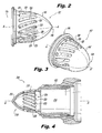
Fig. 3 is a perspective view of the swirler ofFig. 2 , showing the downstream end of the swirler; -
Fig. 4 is a cross-sectional side elevation view of another exemplary embodiment of an injector constructed in accordance with the present invention, showing the swirler mounted in an axially inverted position relative to that shown inFig. 1 ; -
Fig. 5 is a cross-sectional side elevation view of another exemplary embodiment of an injector constructed in accordance with the present invention, showing swirl slots in the swirler that are cylindrical; -
Fig. 6 is a cross-sectional side elevation view of another exemplary embodiment of an injector constructed in accordance with the present invention, showing a swirler wall with a trapezoidal cross-sectional profile; -
Fig. 7 is a cross-sectional side elevation view of another exemplary embodiment of an injector constructed in accordance with the present invention, showing a similar swirler to that shown inFig. 6 , but with a through bore along the axis; -
Fig. 8 is a cross-sectional side elevation view of another exemplary embodiment of an injector constructed in accordance with the present invention, showing a swirler having a swirler wall with a constant diameter; -
Fig. 9 is a cross-sectional side elevation view of another exemplary embodiment of an injector constructed in accordance with the present invention, showing a swirler having a swirler wall that diverges towards the outlet; and -
Fig. 10 is a cross-sectional side elevation view of another exemplary embodiment of an injector constructed in accordance with the present invention, showing a swirler having a converging-diverging swirler wall. - Reference will now be made to the drawings wherein like reference numerals identify similar structural features or aspects of the subject invention. For purposes of explanation and illustration, and not limitation, a partial view of an exemplary embodiment of an injector in accordance with the invention is shown in
Fig. 1 and is designated generally byreference character 100. Other embodiments of injectors in accordance with the invention, or aspects thereof, are provided inFigs. 2-7 , as will be described. The systems and methods of the invention can be used to provide a swirling flow, for example in inner air circuits of fuel inj ectors. - Referring now to
Fig. 1 injector 100 includes aninjector body 102 with opposed inlet andoutlet ends liquid flow circuit 108 passes throughinjector body 102 frominlet end 104 tooutlet end 106. Aninner air circuit 110 is defined throughinjector body 102 along longitudinal axis A. Aswirler 112 is mounted toinjector body 102. - Referring now to
Fig. 2 ,swirler 112 includes aswirler wall 114 extending withininner air circuit 110, as shown inFig. 1 , from an upstream inlet end ofswirler 112 to an opposeddownstream outlet end 118 ofswirler 112 along longitudinal axis A. The inlet end ofswirler 112 defines aninlet opening 116 where air can be introduced to the interior space withinswirler wall 114. A plurality ofswirl slots 120 is defined throughswirler wall 114.Swirl slots 120 are radially off-set with respect to longitudinal axis A. One of theswirl slots 120 is circled to indicate the swirl slot defined directly into and out of the viewing plane as viewed inFig. 2 , which is below longitudinal Axis A. Since all of theswirl slots 120 are radially off-set in this manner, they impart swirl on a flow passing from theinlet opening 116, throughswirl slots 120, and pastdownstream end 118 of the swirler body. - With reference now to
Figs. 2 and 3 , swirlslots 120 are defined through a portion of theswirler wall 114 that converges toward longitudinal axis A in a direction from the inlet opening 116 towardoutlet end 118 of the swirler body.Swirl slots 120 are elongated in a direction alongswirler wall 114. Eachswirl slot 120 extends alongswirler wall 114 in a direction oblique axially and circumferentially relative to longitudinal axis A. In other words, eachslot 120 extends partly circumferentially aroundswirler wall 114 it extends alongswirler wall 114 in the axial direction. - Referring again to
Fig. 1 ,swirler wall 114 defines an axial cross-sectional profile that is bullet-shaped. As also shown inFig. 3 , thedownstream outlet end 118 ofswirler wall 114 is closed off so the only flow path throughswirler wall 114 is throughswirl slots 120. Aflow passage 122 is defined betweenswirler wall 114 and the wall ofinner air circuit 110 ofinjector body 102.Flow passage 122 has a cross-sectional area that increases in the direction along longitudinal axis A towards thedownstream outlet end 118 ofswirler 112.Swirl slots 120 feed intoflow passage 122. This arrangement ofswirl slots 120 and flowpassage 122 causes high velocity air flow to be closer to the fuel injection point ofliquid flow circuit 108 than would be the case for traditional swirlers. This can enhance atomization of the liquid issued fromcircuit 108, for example enhancing fuel atomization in fuel injection applications. - With reference now to
Fig. 4 , another exemplary embodiment of aninjector 200 with aswirler 212 much as described above is shown, in which swirler 212 is mounted to aninjector body 202 and is positioned upstream ofinner air circuit 210. In other words, compared toinjector 100 described above,injector 200 has theswirler 212 flipped axially relative to the orientation described above, so swirlslots 220 are defined through a portion ofswirler wall 214 that diverges relative to the longitudinal axis A in a direction from theupstream end 218 ofswirler 212 todownstream opening 216 ofswirler 212. Whereas ininjector 100 described above, the air flow direction is radially outward throughswirl slots 120, ininjector 200 the flow direction is radially inward throughswirl slots 220. This reversal of the direction ofswirl slots 220 changes the flow characteristics of the swirling flow throughair circuit 210, which can be suitable for certain applications. - Referring now to
Figs. 5-7 , it is contemplated that whileswirl slots Fig. 5 injector 300 includes aninjector body 302 andswirler 312 much as those described above except thatswirl slots 320 are radially off-set cylindrical bores through the swirler wall. This discrete jet type configuration creates a swirling flow pattern that is suitable for certain applications. The swirl slots described herein can all be formed by any suitable process, such as milling or any other suitable process. The milling plane for oneswirl slot 120 indicated with the dashed line around theswirl slot 120 inFig. 1 , is parallel with the viewing plane. Each of the swirlers described herein can be formed as a single piece mounted to the respective injector body by brazing or any other suitable process. - While
injectors injector 400 inFig. 6 includes aswirler 412 having a swirler wall with a trapezoidal cross-sectional profile. Theoutlet end 418 of this swirler body includes a planar portion of the swirler wall that is substantially perpendicular to longitudinal axis A. - Referring now to
Fig. 7 ,injector 500 includes aswirler 512 similar to that described above with reference toFig. 6 except that the outlet end of the swirler body includes abore 524 passing through the swirler wall in an axial direction relative to longitudinalaxis A. Injectors Bore 524 ininjector 500 does not eliminate the flame holding characteristics described above, however it does allow for the flame holding region of the flow to be pushed downstream to allow increased space between the swirler wall and the flame. This can be beneficial in applications where it is desired to have some flame holding characteristics, but where it is also desired to reduce the temperature of the swirler wall for thermal management, for example. Those skilled in the art will readily appreciate that while described as having asingle bore 524 defined in the axial direction, any other suitable number of bores can be used, and in any suitable orientation for a given application. For example, the downstream portion of the swirler wall, e.g.,swirler wall 418, could include multiple bores aligned tangentially to impart swirl on flow passing therethrough. - While described above in the exemplary context of having a single set of swirl slots in each swirler, those skilled in the art will readily appreciate that multiple sets of swirl slots can be used in a swirler. For example, in
injectors - While described above in the exemplary context of injectors with swirlers therein having swirler walls that converge, those skilled in the art will readily appreciate that any other suitable swirler wall profile can be used for a given application. For example,
Figs. 8, 9 and 10 show injectors withswirlers Fig. 10 , for example, the converging-diverging swirler wall is positioned such that the downstream diverging portion of the swirler wall is located at the exit of the liquid spin-chamber. This positioning permits the highest velocity air to be directed across the liquid sheet, providing effective atomization. - One potential benefit of swirlers as described herein over traditional axial type swirlers, which typically include a centerline bluff body, is related to thermally induced stresses. Swirlers as described herein can tend to undergo relatively uniform temperature changes compared to traditional swirlers with bluff bodies. The bluff bodies tend to have large thermal masses, resulting in considerable thermal gradients across the swirl vanes, which is not necessarily the case with swirlers as described herein.
- While shown and described in the exemplary context of air flow through inner air circuits for fuel injectors in gas turbine engines, those skilled in the art will readily appreciate that injectors and swirlers as described herein can be used in any other suitable application. Moreover, injectors and swirlers as described herein can be used to swirl any suitable fluid, including liquids, as needed for specific applications. Various embodiments are described herein with features that vary from embodiment to embodiment to provide different flow characteristics. Those skilled in the art will readily appreciate that any of these features can be adapted and/or used in combination to suit specific applications. Additionally, while the swirlers described herein are shown mounted in exemplary injector bodies, those skilled in the art will readily appreciate that swirlers as described herein can be used in any other suitable type of injector, nozzle, or other envelope without departing from the scope of the invention. In short, the swirlers described herein provide considerable design flexibility so that the flow characteristics can be tailored for specific applications.
- The methods and systems of the present invention, as described above and shown in the drawings, provide for swirlers with superior properties including flow characteristics, thermal management, and adaptability for specific applications. While the apparatus and methods of the subject invention have been shown and described with reference to preferred embodiments, those skilled in the art will readily appreciate that changes and/or modifications may be made thereto without departing from the scope of the subject invention.
Claims (15)
- A swirler (112; 312; 412; 512) comprising:a swirler body with opposed inlet and outlet (118) ends with a swirler wall (114) extending therebetween along a longitudinal axis (A), the inlet end of the swirler body defining an inlet opening (116), wherein a plurality of swirl slots (120; 320) is defined through a portion of the swirler wall that converges toward the longitudinal axis in a direction from the inlet opening toward the outlet end of the swirler body, wherein the swirl slots are radially off-set with respect to the longitudinal axis for imparting swirl on a flow passing from the inlet opening, through the swirl slots, and past the outlet end of the swirler body.
- A swirler as recited in claim 1, wherein the swirl slots (120) are elongated in a direction along the swirler wall, preferably wherein each swirl slot extends along the swirler wall in a direction oblique axially and circumferentially relative to the longitudinal axis.
- A swirler as recited in claim 1 or 2, wherein the swirler wall defines an axial cross-sectional profile that is bullet-shaped or
wherein the swirler wall defines an axial cross-sectional profile that is trapezoidal and wherein the outlet end of the swirler body includes a planar portion of the swirler wall that is substantially perpendicular to the longitudinal axis. - A swirler as recited in claim 1 or 3, wherein the swirl slots (320) are cylindrical bores through the swirler wall.
- A swirler as recited in any preceding claim, wherein the only flow path through the swirler wall is through the swirl slots.
- A swirler as recited in any of claims 1 to 4, wherein the outlet end of the swirler body includes at least one bore (524) passing through the swirler wall in an axial direction relative to the longitudinal axis.
- An injector (100; 300; 400; 500; 600; 700; 800) comprising:an injector body (102; 302) with opposed inlet (104) and outlet (106) ends with a liquid flow circuit (108) passing through the injector body from the inlet end to the outlet end, wherein an inner air circuit (110) is defined through the injector body along a longitudinal axis (A); anda swirler (112; 312; 412; 512) mounted to the injector body having a swirler wall (114) extending within the inner air circuit from an inlet opening (116) of the swirler to a downstream end (118) of the swirler along the longitudinal axis, wherein a plurality of swirl slots (120; 320) is defined through the swirler wall, wherein the swirl slots are radially off-set with respect to the longitudinal axis for imparting swirl on a flow passing from the inlet opening of the swirler through the swirl slots, and past the downstream end of the swirler.
- An injector as recited in claim 7, wherein a flow passage (122) is defined between the swirler wall and a wall of the inner air circuit of the injector body, wherein the flow passage has a cross-sectional area that increases in a direction along the longitudinal axis towards the downstream end of the swirler, preferably wherein the swirl slots feed into the flow passage.
- An injector as recited in claim 7 or 8, wherein the swirl slots (120) are elongated in a direction along the swirler wall, preferably wherein each swirl slot extends along the swirler wall in a direction oblique axially and circumferentially relative to the longitudinal axis.
- An injector as recited in claim 7, 8 or 9, wherein the swirler wall defines an axial cross-sectional profile that is bullet-shaped, or
wherein the swirler wall defines an axial cross-sectional profile that is trapezoidal and wherein the downstream end of the swirler includes a planar portion of the swirler wall that is substantially perpendicular to the longitudinal axis. - An injector as recited in claim 7, 8 or 10, wherein the swirl slots (320) are cylindrical bores through the swirler wall.
- An injector as recited in claim 7, 8, 9, 10 or 11 wherein the only flow path through the swirler wall is through the swirl slots.
- An injector as recited in claim 7, 8, 9, 10 or 11, wherein the downstream end of the swirler includes at least one bore (524) passing through the swirler wall in an axial direction relative to the longitudinal axis.
- An injector (200) comprising:an injector body (202) with opposed inlet and outlet ends with a liquid flow circuit passing through the injector body from the inlet end to the outlet end, wherein an inner air circuit (210) is defined through the injector body along a longitudinal axis (A); anda swirler (212) mounted to the injector body upstream of the inner air circuit, the swirler having a swirler wall (214) extending from an upstream end of the swirler along the longitudinal axis to a downstream opening of the swirler feeding into the inner air circuit of the injector body, wherein a plurality of swirl slots (220) is defined through the swirler wall, wherein the swirl slots are radially off-set with respect to the longitudinal axis for imparting swirl on a flow passing in through the swirl slots, through the downstream opening of the swirler, and into the inner air circuit of the injector body, wherein the swirl slots are defined through a portion of the swirler wall that diverges relative to the longitudinal axis in a direction from the upstream end of the swirler to the downstream opening of the swirler.
- An injector as recited in claim 14, wherein the swirl slots are elongated in a direction along the swirler wall, wherein each swirl slot extends along the swirler wall in a direction oblique axially and circumferentially relative to the longitudinal axis, and wherein the swirler wall defines an axial cross-sectional profile that is bullet-shaped.
Applications Claiming Priority (1)
| Application Number | Priority Date | Filing Date | Title |
|---|---|---|---|
| US13/783,832 US10161633B2 (en) | 2013-03-04 | 2013-03-04 | Air swirlers |
Publications (3)
| Publication Number | Publication Date |
|---|---|
| EP2775202A2 true EP2775202A2 (en) | 2014-09-10 |
| EP2775202A3 EP2775202A3 (en) | 2015-01-07 |
| EP2775202B1 EP2775202B1 (en) | 2017-10-18 |
Family
ID=50190336
Family Applications (1)
| Application Number | Title | Priority Date | Filing Date |
|---|---|---|---|
| EP14157662.9A Active EP2775202B1 (en) | 2013-03-04 | 2014-03-04 | Air swirlers |
Country Status (2)
| Country | Link |
|---|---|
| US (2) | US10161633B2 (en) |
| EP (1) | EP2775202B1 (en) |
Cited By (4)
| Publication number | Priority date | Publication date | Assignee | Title |
|---|---|---|---|---|
| EP3076083A1 (en) * | 2015-03-31 | 2016-10-05 | Delavan Inc | Fuel nozzles |
| US9897321B2 (en) | 2015-03-31 | 2018-02-20 | Delavan Inc. | Fuel nozzles |
| US10309651B2 (en) | 2011-11-03 | 2019-06-04 | Delavan Inc | Injectors for multipoint injection |
| EP3553382A1 (en) * | 2018-04-10 | 2019-10-16 | Delavan, Inc. | Fuel injectors for turbomachines having inner air swirling |
Families Citing this family (14)
| Publication number | Priority date | Publication date | Assignee | Title |
|---|---|---|---|---|
| EP3224544A1 (en) * | 2014-11-26 | 2017-10-04 | Siemens Aktiengesellschaft | Fuel lance with means for interacting with a flow of air and improve breakage of an ejected liquid jet of fuel |
| US9939155B2 (en) * | 2015-01-26 | 2018-04-10 | Delavan Inc. | Flexible swirlers |
| US9863638B2 (en) * | 2015-04-01 | 2018-01-09 | Delavan Inc. | Air shrouds with improved air wiping |
| US10132500B2 (en) * | 2015-10-16 | 2018-11-20 | Delavan Inc. | Airblast injectors |
| US11041621B2 (en) * | 2016-07-26 | 2021-06-22 | Jfe Steel Corporation | Auxiliary burner for electric furnace |
| US10955138B2 (en) * | 2017-04-25 | 2021-03-23 | Parker-Hannifin Corporation | Airblast fuel nozzle |
| US11131459B2 (en) | 2017-09-26 | 2021-09-28 | Delavan Inc. | Combustor with an air mixer and an air swirler each having slots |
| US11143406B2 (en) * | 2018-04-10 | 2021-10-12 | Delavan Inc. | Fuel injectors having air sealing structures |
| CN109059534B (en) * | 2018-06-12 | 2024-02-23 | 湖北锋焰机电科技有限公司 | Adjustable high-efficiency energy-saving rotary kiln burner |
| US10935245B2 (en) * | 2018-11-20 | 2021-03-02 | General Electric Company | Annular concentric fuel nozzle assembly with annular depression and radial inlet ports |
| CN109915826A (en) * | 2019-03-19 | 2019-06-21 | 苏州墨华高科信息技术有限公司 | A nozzle combining a spinning swirl trough and a swirl chamber |
| EP3896337A1 (en) * | 2020-04-16 | 2021-10-20 | General Electric Company | Combustion system for a boiler with fuel stream distribution means in a burner and method of combustion |
| CN111706878A (en) * | 2020-06-01 | 2020-09-25 | 滁州帝邦科技有限公司 | Double oil circuit hedging direct injection nozzle |
| JP2024101934A (en) * | 2023-01-18 | 2024-07-30 | トヨタ自動車株式会社 | Combustor and combustion nozzle suitable for hydrogen gas turbine |
Family Cites Families (14)
| Publication number | Priority date | Publication date | Assignee | Title |
|---|---|---|---|---|
| US1462395A (en) * | 1922-06-12 | 1923-07-17 | Smith S Dock Company Ltd | Construction of spraying nozzles or atomizers |
| GB2062839B (en) * | 1979-09-13 | 1983-12-14 | Rolls Royce | Gas turbine engine fuel burner |
| US4941617A (en) * | 1988-12-14 | 1990-07-17 | United Technologies Corporation | Airblast fuel nozzle |
| DE69414107T2 (en) | 1993-06-01 | 1999-04-29 | Pratt & Whitney Canada Inc., Longueuil, Quebec | RADIAL AIR COMPRESSOR INJECTOR FOR FUEL |
| US5850732A (en) * | 1997-05-13 | 1998-12-22 | Capstone Turbine Corporation | Low emissions combustion system for a gas turbine engine |
| US6360776B1 (en) * | 2000-11-01 | 2002-03-26 | Rolls-Royce Corporation | Apparatus for premixing in a gas turbine engine |
| US6698208B2 (en) | 2001-12-14 | 2004-03-02 | Elliott Energy Systems, Inc. | Atomizer for a combustor |
| US8348180B2 (en) | 2004-06-09 | 2013-01-08 | Delavan Inc | Conical swirler for fuel injectors and combustor domes and methods of manufacturing the same |
| US7926282B2 (en) | 2008-03-04 | 2011-04-19 | Delavan Inc | Pure air blast fuel injector |
| US8667800B2 (en) | 2009-05-13 | 2014-03-11 | Delavan Inc. | Flameless combustion systems for gas turbine engines |
| US8313046B2 (en) * | 2009-08-04 | 2012-11-20 | Delavan Inc | Multi-point injector ring |
| US8925325B2 (en) | 2011-03-18 | 2015-01-06 | Delavan Inc. | Recirculating product injection nozzle |
| US9188063B2 (en) | 2011-11-03 | 2015-11-17 | Delavan Inc. | Injectors for multipoint injection |
| US9644844B2 (en) * | 2011-11-03 | 2017-05-09 | Delavan Inc. | Multipoint fuel injection arrangements |
-
2013
- 2013-03-04 US US13/783,832 patent/US10161633B2/en active Active
-
2014
- 2014-03-04 EP EP14157662.9A patent/EP2775202B1/en active Active
-
2018
- 2018-11-30 US US16/206,302 patent/US20190101291A1/en not_active Abandoned
Non-Patent Citations (1)
| Title |
|---|
| None |
Cited By (7)
| Publication number | Priority date | Publication date | Assignee | Title |
|---|---|---|---|---|
| US10309651B2 (en) | 2011-11-03 | 2019-06-04 | Delavan Inc | Injectors for multipoint injection |
| EP3076083A1 (en) * | 2015-03-31 | 2016-10-05 | Delavan Inc | Fuel nozzles |
| US9897321B2 (en) | 2015-03-31 | 2018-02-20 | Delavan Inc. | Fuel nozzles |
| US10385809B2 (en) | 2015-03-31 | 2019-08-20 | Delavan Inc. | Fuel nozzles |
| US11111888B2 (en) | 2015-03-31 | 2021-09-07 | Delavan Inc. | Fuel nozzles |
| EP3553382A1 (en) * | 2018-04-10 | 2019-10-16 | Delavan, Inc. | Fuel injectors for turbomachines having inner air swirling |
| US10788214B2 (en) | 2018-04-10 | 2020-09-29 | Delavan Inc. | Fuel injectors for turbomachines having inner air swirling |
Also Published As
| Publication number | Publication date |
|---|---|
| US20140245742A1 (en) | 2014-09-04 |
| EP2775202A3 (en) | 2015-01-07 |
| EP2775202B1 (en) | 2017-10-18 |
| US10161633B2 (en) | 2018-12-25 |
| US20190101291A1 (en) | 2019-04-04 |
Similar Documents
| Publication | Publication Date | Title |
|---|---|---|
| US10161633B2 (en) | Air swirlers | |
| US9625146B2 (en) | Swirl slot relief in a liquid swirler | |
| US7926744B2 (en) | Radially outward flowing air-blast fuel injector for gas turbine engine | |
| EP3346187B1 (en) | Fuel injectors and methods of use in gas turbine combustor | |
| US9488108B2 (en) | Radial vane inner air swirlers | |
| US11628455B2 (en) | Atomizers | |
| EP3076082A1 (en) | Fuel nozzles | |
| US10883719B2 (en) | Prefilming fuel/air mixer | |
| US9835334B2 (en) | Air entrance effect | |
| US11649963B2 (en) | Liquid fuel injector | |
| US9689571B2 (en) | Offset stem fuel distributor | |
| CN107166434A (en) | A kind of fuel-rich autothermic cracking burner | |
| US8943834B2 (en) | Pre-mixing injector with bladeless swirler | |
| EP2735797B1 (en) | Gas turbine combustor | |
| EP3460333B1 (en) | Combustor system |
Legal Events
| Date | Code | Title | Description |
|---|---|---|---|
| PUAI | Public reference made under article 153(3) epc to a published international application that has entered the european phase |
Free format text: ORIGINAL CODE: 0009012 |
|
| 17P | Request for examination filed |
Effective date: 20140304 |
|
| AK | Designated contracting states |
Kind code of ref document: A2 Designated state(s): AL AT BE BG CH CY CZ DE DK EE ES FI FR GB GR HR HU IE IS IT LI LT LU LV MC MK MT NL NO PL PT RO RS SE SI SK SM TR |
|
| AX | Request for extension of the european patent |
Extension state: BA ME |
|
| PUAL | Search report despatched |
Free format text: ORIGINAL CODE: 0009013 |
|
| AK | Designated contracting states |
Kind code of ref document: A3 Designated state(s): AL AT BE BG CH CY CZ DE DK EE ES FI FR GB GR HR HU IE IS IT LI LT LU LV MC MK MT NL NO PL PT RO RS SE SI SK SM TR |
|
| AX | Request for extension of the european patent |
Extension state: BA ME |
|
| RIC1 | Information provided on ipc code assigned before grant |
Ipc: F23C 7/00 20060101AFI20141128BHEP Ipc: F23D 11/38 20060101ALI20141128BHEP Ipc: F23R 3/12 20060101ALI20141128BHEP Ipc: F23R 3/28 20060101ALI20141128BHEP Ipc: F23D 11/10 20060101ALI20141128BHEP |
|
| R17P | Request for examination filed (corrected) |
Effective date: 20150707 |
|
| RBV | Designated contracting states (corrected) |
Designated state(s): AL AT BE BG CH CY CZ DE DK EE ES FI FR GB GR HR HU IE IS IT LI LT LU LV MC MK MT NL NO PL PT RO RS SE SI SK SM TR |
|
| 17Q | First examination report despatched |
Effective date: 20151218 |
|
| STAA | Information on the status of an ep patent application or granted ep patent |
Free format text: STATUS: EXAMINATION IS IN PROGRESS |
|
| GRAP | Despatch of communication of intention to grant a patent |
Free format text: ORIGINAL CODE: EPIDOSNIGR1 |
|
| STAA | Information on the status of an ep patent application or granted ep patent |
Free format text: STATUS: GRANT OF PATENT IS INTENDED |
|
| INTG | Intention to grant announced |
Effective date: 20170424 |
|
| GRAS | Grant fee paid |
Free format text: ORIGINAL CODE: EPIDOSNIGR3 |
|
| GRAA | (expected) grant |
Free format text: ORIGINAL CODE: 0009210 |
|
| STAA | Information on the status of an ep patent application or granted ep patent |
Free format text: STATUS: THE PATENT HAS BEEN GRANTED |
|
| AK | Designated contracting states |
Kind code of ref document: B1 Designated state(s): AL AT BE BG CH CY CZ DE DK EE ES FI FR GB GR HR HU IE IS IT LI LT LU LV MC MK MT NL NO PL PT RO RS SE SI SK SM TR |
|
| REG | Reference to a national code |
Ref country code: GB Ref legal event code: FG4D |
|
| REG | Reference to a national code |
Ref country code: CH Ref legal event code: EP |
|
| REG | Reference to a national code |
Ref country code: AT Ref legal event code: REF Ref document number: 938291 Country of ref document: AT Kind code of ref document: T Effective date: 20171115 Ref country code: IE Ref legal event code: FG4D |
|
| REG | Reference to a national code |
Ref country code: DE Ref legal event code: R096 Ref document number: 602014015855 Country of ref document: DE |
|
| REG | Reference to a national code |
Ref country code: FR Ref legal event code: PLFP Year of fee payment: 5 |
|
| REG | Reference to a national code |
Ref country code: NL Ref legal event code: MP Effective date: 20171018 |
|
| REG | Reference to a national code |
Ref country code: LT Ref legal event code: MG4D |
|
| REG | Reference to a national code |
Ref country code: AT Ref legal event code: MK05 Ref document number: 938291 Country of ref document: AT Kind code of ref document: T Effective date: 20171018 |
|
| PG25 | Lapsed in a contracting state [announced via postgrant information from national office to epo] |
Ref country code: NL Free format text: LAPSE BECAUSE OF FAILURE TO SUBMIT A TRANSLATION OF THE DESCRIPTION OR TO PAY THE FEE WITHIN THE PRESCRIBED TIME-LIMIT Effective date: 20171018 |
|
| PG25 | Lapsed in a contracting state [announced via postgrant information from national office to epo] |
Ref country code: NO Free format text: LAPSE BECAUSE OF FAILURE TO SUBMIT A TRANSLATION OF THE DESCRIPTION OR TO PAY THE FEE WITHIN THE PRESCRIBED TIME-LIMIT Effective date: 20180118 Ref country code: ES Free format text: LAPSE BECAUSE OF FAILURE TO SUBMIT A TRANSLATION OF THE DESCRIPTION OR TO PAY THE FEE WITHIN THE PRESCRIBED TIME-LIMIT Effective date: 20171018 Ref country code: FI Free format text: LAPSE BECAUSE OF FAILURE TO SUBMIT A TRANSLATION OF THE DESCRIPTION OR TO PAY THE FEE WITHIN THE PRESCRIBED TIME-LIMIT Effective date: 20171018 Ref country code: SE Free format text: LAPSE BECAUSE OF FAILURE TO SUBMIT A TRANSLATION OF THE DESCRIPTION OR TO PAY THE FEE WITHIN THE PRESCRIBED TIME-LIMIT Effective date: 20171018 Ref country code: LT Free format text: LAPSE BECAUSE OF FAILURE TO SUBMIT A TRANSLATION OF THE DESCRIPTION OR TO PAY THE FEE WITHIN THE PRESCRIBED TIME-LIMIT Effective date: 20171018 |
|
| PG25 | Lapsed in a contracting state [announced via postgrant information from national office to epo] |
Ref country code: HR Free format text: LAPSE BECAUSE OF FAILURE TO SUBMIT A TRANSLATION OF THE DESCRIPTION OR TO PAY THE FEE WITHIN THE PRESCRIBED TIME-LIMIT Effective date: 20171018 Ref country code: IS Free format text: LAPSE BECAUSE OF FAILURE TO SUBMIT A TRANSLATION OF THE DESCRIPTION OR TO PAY THE FEE WITHIN THE PRESCRIBED TIME-LIMIT Effective date: 20180218 Ref country code: RS Free format text: LAPSE BECAUSE OF FAILURE TO SUBMIT A TRANSLATION OF THE DESCRIPTION OR TO PAY THE FEE WITHIN THE PRESCRIBED TIME-LIMIT Effective date: 20171018 Ref country code: BG Free format text: LAPSE BECAUSE OF FAILURE TO SUBMIT A TRANSLATION OF THE DESCRIPTION OR TO PAY THE FEE WITHIN THE PRESCRIBED TIME-LIMIT Effective date: 20180118 Ref country code: AT Free format text: LAPSE BECAUSE OF FAILURE TO SUBMIT A TRANSLATION OF THE DESCRIPTION OR TO PAY THE FEE WITHIN THE PRESCRIBED TIME-LIMIT Effective date: 20171018 Ref country code: GR Free format text: LAPSE BECAUSE OF FAILURE TO SUBMIT A TRANSLATION OF THE DESCRIPTION OR TO PAY THE FEE WITHIN THE PRESCRIBED TIME-LIMIT Effective date: 20180119 Ref country code: LV Free format text: LAPSE BECAUSE OF FAILURE TO SUBMIT A TRANSLATION OF THE DESCRIPTION OR TO PAY THE FEE WITHIN THE PRESCRIBED TIME-LIMIT Effective date: 20171018 |
|
| REG | Reference to a national code |
Ref country code: DE Ref legal event code: R097 Ref document number: 602014015855 Country of ref document: DE |
|
| PG25 | Lapsed in a contracting state [announced via postgrant information from national office to epo] |
Ref country code: CZ Free format text: LAPSE BECAUSE OF FAILURE TO SUBMIT A TRANSLATION OF THE DESCRIPTION OR TO PAY THE FEE WITHIN THE PRESCRIBED TIME-LIMIT Effective date: 20171018 Ref country code: SK Free format text: LAPSE BECAUSE OF FAILURE TO SUBMIT A TRANSLATION OF THE DESCRIPTION OR TO PAY THE FEE WITHIN THE PRESCRIBED TIME-LIMIT Effective date: 20171018 Ref country code: EE Free format text: LAPSE BECAUSE OF FAILURE TO SUBMIT A TRANSLATION OF THE DESCRIPTION OR TO PAY THE FEE WITHIN THE PRESCRIBED TIME-LIMIT Effective date: 20171018 Ref country code: DK Free format text: LAPSE BECAUSE OF FAILURE TO SUBMIT A TRANSLATION OF THE DESCRIPTION OR TO PAY THE FEE WITHIN THE PRESCRIBED TIME-LIMIT Effective date: 20171018 |
|
| PLBE | No opposition filed within time limit |
Free format text: ORIGINAL CODE: 0009261 |
|
| STAA | Information on the status of an ep patent application or granted ep patent |
Free format text: STATUS: NO OPPOSITION FILED WITHIN TIME LIMIT |
|
| PG25 | Lapsed in a contracting state [announced via postgrant information from national office to epo] |
Ref country code: PL Free format text: LAPSE BECAUSE OF FAILURE TO SUBMIT A TRANSLATION OF THE DESCRIPTION OR TO PAY THE FEE WITHIN THE PRESCRIBED TIME-LIMIT Effective date: 20171018 Ref country code: RO Free format text: LAPSE BECAUSE OF FAILURE TO SUBMIT A TRANSLATION OF THE DESCRIPTION OR TO PAY THE FEE WITHIN THE PRESCRIBED TIME-LIMIT Effective date: 20171018 Ref country code: SM Free format text: LAPSE BECAUSE OF FAILURE TO SUBMIT A TRANSLATION OF THE DESCRIPTION OR TO PAY THE FEE WITHIN THE PRESCRIBED TIME-LIMIT Effective date: 20171018 Ref country code: IT Free format text: LAPSE BECAUSE OF FAILURE TO SUBMIT A TRANSLATION OF THE DESCRIPTION OR TO PAY THE FEE WITHIN THE PRESCRIBED TIME-LIMIT Effective date: 20171018 |
|
| 26N | No opposition filed |
Effective date: 20180719 |
|
| REG | Reference to a national code |
Ref country code: CH Ref legal event code: PL |
|
| PG25 | Lapsed in a contracting state [announced via postgrant information from national office to epo] |
Ref country code: SI Free format text: LAPSE BECAUSE OF FAILURE TO SUBMIT A TRANSLATION OF THE DESCRIPTION OR TO PAY THE FEE WITHIN THE PRESCRIBED TIME-LIMIT Effective date: 20171018 Ref country code: MC Free format text: LAPSE BECAUSE OF FAILURE TO SUBMIT A TRANSLATION OF THE DESCRIPTION OR TO PAY THE FEE WITHIN THE PRESCRIBED TIME-LIMIT Effective date: 20171018 |
|
| REG | Reference to a national code |
Ref country code: BE Ref legal event code: MM Effective date: 20180331 |
|
| REG | Reference to a national code |
Ref country code: IE Ref legal event code: MM4A |
|
| PG25 | Lapsed in a contracting state [announced via postgrant information from national office to epo] |
Ref country code: LU Free format text: LAPSE BECAUSE OF NON-PAYMENT OF DUE FEES Effective date: 20180304 |
|
| PG25 | Lapsed in a contracting state [announced via postgrant information from national office to epo] |
Ref country code: IE Free format text: LAPSE BECAUSE OF NON-PAYMENT OF DUE FEES Effective date: 20180304 |
|
| PG25 | Lapsed in a contracting state [announced via postgrant information from national office to epo] |
Ref country code: CH Free format text: LAPSE BECAUSE OF NON-PAYMENT OF DUE FEES Effective date: 20180331 Ref country code: LI Free format text: LAPSE BECAUSE OF NON-PAYMENT OF DUE FEES Effective date: 20180331 Ref country code: BE Free format text: LAPSE BECAUSE OF NON-PAYMENT OF DUE FEES Effective date: 20180331 |
|
| PG25 | Lapsed in a contracting state [announced via postgrant information from national office to epo] |
Ref country code: MT Free format text: LAPSE BECAUSE OF NON-PAYMENT OF DUE FEES Effective date: 20180304 |
|
| PG25 | Lapsed in a contracting state [announced via postgrant information from national office to epo] |
Ref country code: TR Free format text: LAPSE BECAUSE OF FAILURE TO SUBMIT A TRANSLATION OF THE DESCRIPTION OR TO PAY THE FEE WITHIN THE PRESCRIBED TIME-LIMIT Effective date: 20171018 |
|
| PG25 | Lapsed in a contracting state [announced via postgrant information from national office to epo] |
Ref country code: PT Free format text: LAPSE BECAUSE OF FAILURE TO SUBMIT A TRANSLATION OF THE DESCRIPTION OR TO PAY THE FEE WITHIN THE PRESCRIBED TIME-LIMIT Effective date: 20171018 Ref country code: HU Free format text: LAPSE BECAUSE OF FAILURE TO SUBMIT A TRANSLATION OF THE DESCRIPTION OR TO PAY THE FEE WITHIN THE PRESCRIBED TIME-LIMIT; INVALID AB INITIO Effective date: 20140304 |
|
| PG25 | Lapsed in a contracting state [announced via postgrant information from national office to epo] |
Ref country code: CY Free format text: LAPSE BECAUSE OF FAILURE TO SUBMIT A TRANSLATION OF THE DESCRIPTION OR TO PAY THE FEE WITHIN THE PRESCRIBED TIME-LIMIT Effective date: 20171018 Ref country code: MK Free format text: LAPSE BECAUSE OF NON-PAYMENT OF DUE FEES Effective date: 20171018 |
|
| PG25 | Lapsed in a contracting state [announced via postgrant information from national office to epo] |
Ref country code: AL Free format text: LAPSE BECAUSE OF FAILURE TO SUBMIT A TRANSLATION OF THE DESCRIPTION OR TO PAY THE FEE WITHIN THE PRESCRIBED TIME-LIMIT Effective date: 20171018 |
|
| P01 | Opt-out of the competence of the unified patent court (upc) registered |
Effective date: 20230530 |
|
| PGFP | Annual fee paid to national office [announced via postgrant information from national office to epo] |
Ref country code: DE Payment date: 20250218 Year of fee payment: 12 |
|
| PGFP | Annual fee paid to national office [announced via postgrant information from national office to epo] |
Ref country code: FR Payment date: 20250218 Year of fee payment: 12 |
|
| PGFP | Annual fee paid to national office [announced via postgrant information from national office to epo] |
Ref country code: GB Payment date: 20250221 Year of fee payment: 12 |