EP2775182A1 - Solenoid valve control device - Google Patents
Solenoid valve control device Download PDFInfo
- Publication number
- EP2775182A1 EP2775182A1 EP20140154480 EP14154480A EP2775182A1 EP 2775182 A1 EP2775182 A1 EP 2775182A1 EP 20140154480 EP20140154480 EP 20140154480 EP 14154480 A EP14154480 A EP 14154480A EP 2775182 A1 EP2775182 A1 EP 2775182A1
- Authority
- EP
- European Patent Office
- Prior art keywords
- solenoid valve
- operations
- control device
- microcomputer
- valve control
- Prior art date
- Legal status (The legal status is an assumption and is not a legal conclusion. Google has not performed a legal analysis and makes no representation as to the accuracy of the status listed.)
- Withdrawn
Links
- 230000005540 biological transmission Effects 0.000 claims abstract description 35
- 238000004891 communication Methods 0.000 claims description 36
- 238000004378 air conditioning Methods 0.000 description 44
- 230000001186 cumulative effect Effects 0.000 description 16
- 239000003507 refrigerant Substances 0.000 description 15
- 238000001514 detection method Methods 0.000 description 9
- 238000012423 maintenance Methods 0.000 description 8
- 238000001816 cooling Methods 0.000 description 5
- 238000005057 refrigeration Methods 0.000 description 5
- 238000007689 inspection Methods 0.000 description 3
- 230000000737 periodic effect Effects 0.000 description 3
- 238000010586 diagram Methods 0.000 description 2
- RXQCGGRTAILOIN-UHFFFAOYSA-N mephentermine Chemical compound CNC(C)(C)CC1=CC=CC=C1 RXQCGGRTAILOIN-UHFFFAOYSA-N 0.000 description 2
- 229960002342 mephentermine Drugs 0.000 description 2
- 230000007423 decrease Effects 0.000 description 1
- 230000000694 effects Effects 0.000 description 1
- 238000005516 engineering process Methods 0.000 description 1
- 230000005669 field effect Effects 0.000 description 1
- 239000002184 metal Substances 0.000 description 1
- 229910044991 metal oxide Inorganic materials 0.000 description 1
- 150000004706 metal oxides Chemical class 0.000 description 1
- 230000002093 peripheral effect Effects 0.000 description 1
- 238000010992 reflux Methods 0.000 description 1
- 239000011347 resin Substances 0.000 description 1
- 229920005989 resin Polymers 0.000 description 1
- 239000004065 semiconductor Substances 0.000 description 1
- 238000005476 soldering Methods 0.000 description 1
- 239000007787 solid Substances 0.000 description 1
Images


Classifications
-
- F—MECHANICAL ENGINEERING; LIGHTING; HEATING; WEAPONS; BLASTING
- F16—ENGINEERING ELEMENTS AND UNITS; GENERAL MEASURES FOR PRODUCING AND MAINTAINING EFFECTIVE FUNCTIONING OF MACHINES OR INSTALLATIONS; THERMAL INSULATION IN GENERAL
- F16K—VALVES; TAPS; COCKS; ACTUATING-FLOATS; DEVICES FOR VENTING OR AERATING
- F16K37/00—Special means in or on valves or other cut-off apparatus for indicating or recording operation thereof, or for enabling an alarm to be given
- F16K37/0025—Electrical or magnetic means
- F16K37/0041—Electrical or magnetic means for measuring valve parameters
-
- F—MECHANICAL ENGINEERING; LIGHTING; HEATING; WEAPONS; BLASTING
- F16—ENGINEERING ELEMENTS AND UNITS; GENERAL MEASURES FOR PRODUCING AND MAINTAINING EFFECTIVE FUNCTIONING OF MACHINES OR INSTALLATIONS; THERMAL INSULATION IN GENERAL
- F16K—VALVES; TAPS; COCKS; ACTUATING-FLOATS; DEVICES FOR VENTING OR AERATING
- F16K31/00—Actuating devices; Operating means; Releasing devices
- F16K31/02—Actuating devices; Operating means; Releasing devices electric; magnetic
- F16K31/06—Actuating devices; Operating means; Releasing devices electric; magnetic using a magnet, e.g. diaphragm valves, cutting off by means of a liquid
-
- F—MECHANICAL ENGINEERING; LIGHTING; HEATING; WEAPONS; BLASTING
- F16—ENGINEERING ELEMENTS AND UNITS; GENERAL MEASURES FOR PRODUCING AND MAINTAINING EFFECTIVE FUNCTIONING OF MACHINES OR INSTALLATIONS; THERMAL INSULATION IN GENERAL
- F16K—VALVES; TAPS; COCKS; ACTUATING-FLOATS; DEVICES FOR VENTING OR AERATING
- F16K37/00—Special means in or on valves or other cut-off apparatus for indicating or recording operation thereof, or for enabling an alarm to be given
- F16K37/0075—For recording or indicating the functioning of a valve in combination with test equipment
- F16K37/0083—For recording or indicating the functioning of a valve in combination with test equipment by measuring valve parameters
-
- Y—GENERAL TAGGING OF NEW TECHNOLOGICAL DEVELOPMENTS; GENERAL TAGGING OF CROSS-SECTIONAL TECHNOLOGIES SPANNING OVER SEVERAL SECTIONS OF THE IPC; TECHNICAL SUBJECTS COVERED BY FORMER USPC CROSS-REFERENCE ART COLLECTIONS [XRACs] AND DIGESTS
- Y10—TECHNICAL SUBJECTS COVERED BY FORMER USPC
- Y10T—TECHNICAL SUBJECTS COVERED BY FORMER US CLASSIFICATION
- Y10T137/00—Fluid handling
- Y10T137/8158—With indicator, register, recorder, alarm or inspection means
Definitions
- the present invention relates to a solenoid valve control device, for example, a control device of a solenoid valve used in an air conditioning system for vehicles.
- a solenoid valve controlling a flow of a refrigerant to the front air conditioner and a solenoid valve controlling a flow of a refrigerant to the rear air conditioner are used.
- the solenoid valve for the front air conditioner opens to pass the refrigerant to the front air conditioner.
- the solenoid valve for the front air conditioner closes to stop the flow of the refrigerant to the front air conditioner.
- the solenoid valve for the rear air conditioner opens to pass the refrigerant to the rear air conditioner.
- the solenoid valve for the rear air conditioner closes to stop the flow of the refrigerant to the rear air conditioner (for example, Japanese Patent Application Laid-Open, No. 7-117455 ).
- the solenoid valve used in the above air conditioning system there are two types, which are a normal open type and a normal close type.
- the solenoid valve of the normal open type opens in a de-energized state and closes by operating the valve when in an energized state.
- the solenoid valve of the normal close type closes in a de-energized state and opens by operating the valve when in an energized state.
- the above solenoid valve has a life of durability since it is a mechanical part, so that limitation of number of operations, for example, 100,000 times, is provided.
- Japanese Patent No. 4431996 disclosed a technology improving the reliability to the use limitation period (life) of a solenoid valve.
- a drive circuit of the solenoid valve disclosed in Japanese Patent No. 4431996 includes a solenoid valve operation detection unit, a detection result storage unit, and a cumulative number of operations determination unit.
- the solenoid valve operation detection unit detects that the solenoid valve is in an operation, based on a current detection value.
- the detection result storage unit stores a detection result detected by the solenoid valve operation detection unit.
- the cumulative number of operations determination unit calculates a cumulative number of operations of the solenoid valve from each detection result stored in the detection result storage unit and determines whether the cumulative number of operations overs the predetermined first number of operations.
- the cumulative number of operations determination unit determines that the cumulative number of operations overs the first number of operations
- the cumulative number of operations determination unit outputs a pulse width change signal which instructs to change a pulse width of a first pulse signal.
- the cumulative number of operations determination unit determines that the cumulative number of operations overs a second number of operations, which is set to be greater than the first number of operations
- the cumulative number of operations determination unit externally outputs a use time limitation notification signal which notifies that the solenoid valve reaches a time limitation of use.
- the cumulative number of operations determination unit determines that the cumulative number of operations overs the predetermined cumulative number of operations
- the cumulative number of operations determination unit externally outputs the use time limitation notification signal notifying that the solenoid valve reaches the time limitation of use.
- a user, or the like can promptly replace the solenoid valve, which reaches the time limitation of use (life) by receiving the information.
- the present invention was conceived in view of above problems, and is directed to provide a solenoid valve control device, in which a user, or the like, can preciously grasps the state of the solenoid valve based on the number of operations.
- a solenoid valve control device is a solenoid valve control device controlling a solenoid valve, and includes a storage unit storing the number of operations concerning opening/closing of the solenoid valve and a transmission unit externally transmitting the number of operations stored in the storage unit.
- the transmission unit when the number of operations stored in the storage unit overs the limitation number of times concerning the life of the solenoid valve, the transmission unit externally outputs an alarm signal.
- the limitation number of times is the number of operations acceptable on durability of the solenoid valve.
- the number of operations is any one of the number of times of opening, the number of times of closing, and the number of times of energizing of the solenoid valve.
- the transmission unit externally transmits by a local interconnect network (LIN) communication or a controller area network (CAN) communication.
- the storage unit is a non-volatile memory.
- the transmission unit externally transmits the number of operations concerning the solenoid valve, and thereby the user, or the like, can preciously grasp the number of operations of opening/closing of the solenoid valve at a desired time. Further, when the number of operations stored in the storage unit becomes equal to or greater than the limitation number of times concerning the life of the solenoid valve, parkicularly, equal to or greater than the number of operations acceptable on durability of the solenoid valve, the transmission unit externally transmits the alarm signal. By this operation, the user can reliably grasp that the solenoid valve is at the time of replacement.
- the number of operations is any one of the number of times of opening, number of times of closing, and number of times of energizing of the valve, the user can preciously grasp the number of operations concerning the opening/closing of the solenoid valve.
- the transmission unit externally communicates by the LIN communication or the CAN communication which are conventionally used in vehicles, or the like, the solenoid valve control device is simply applicable to the air conditioning system for vehicles (car air conditioner) without building a new communication network.
- the solenoid valve control device can reliably store the number of operations of the solenoid valve in the storage unit, even when the solenoid valve control device operates in a sleep mode reducing power consumption, or power supply of the solenoid valve control device is stopped.
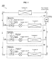
- Fig. 1 explains a refrigeration cycle of the air conditioning system in which a solenoid valve control device according to the present invention is adapted.
- Fig. 1 explains a cooling cycle of the air conditioning system for an electric vehicle mounting a battery.
- an arrow in Fig. 1 indicates a flow direction of refrigeration at a time of cooling.
- the air conditioning system 100 illustrated in Fig. 1 (for example, a car air conditioner) includes a front air conditioner 10, a rear air conditioner 20, a battery air conditioner, a compressor 40, and a condenser 50. These equipment are connected each other by piping and a refrigeration circulates in them, so that the refrigeration cycle is constituted.
- the front air conditioner 10 is used, for example, for air conditioning of the front seats in a vehicle interior and includes a solenoid valve device 11, an expansion valve 15, and an evaporator 16. Further, the solenoid valve device 11 has a structure in which a solenoid valve control device 13 for controlling the opening/closing of a solenoid valve 12 is integrally attached to the solenoid valve 12.
- the rear air conditioner 20 is used, for example, for air conditioning of the rear seats in the vehicle interior and includes a solenoid valve device 21, an expansion valve 25, and an evaporator 26.
- the solenoid valve device 21 has a structure in which a solenoid valve control device 23 for controlling the opening/closing of a solenoid valve 22 is integrally attached to the solenoid valve 22.
- the battery air conditioner 30 is used, for example, for cooling a battery mounted in a vehicle and includes a solenoid valve device 31, an expansion valve 35, and an evaporator 36.
- the solenoid valve device 31 has a structure in which a solenoid valve control device 33 for controlling the opening/closing of a solenoid valve 32 is integrally attached to the solenoid valve 32.
- the refrigerant flows to the evaporator 16 through the solenoid valve 12 and the expansion valve 15, so that the front seats in the vehicle interior can be cooled.
- the solenoid valve 22 by opening the solenoid valve control device 23 in the solenoid valve device 21 in the rear air conditioner 20, the refrigerant flows to the evaporator 26 through the solenoid valve 22 and the expansion valve 25, so that the rear seats in the vehicle interior can be cooled.
- the refrigerant flows to the evaporator 36 through the solenoid valve 32 and the expansion valve 35, so that the battery mounted in the vehicle can be cooled.
- the solenoid valve control device 33 in the solenoid valve device 31 in the battery air conditioner closes the solenoid valve 32, the flow of the refrigerant flowing to the evaporator 36 through the solenoid valve 32 and the expansion valve 35 is blocked.
- the solenoid valve control device 13 in the solenoid valve device 11 in the front air conditioner 10 closes the solenoid valve 12 and the solenoid valve control device 23 in the solenoid valve device 21 in the rear air conditioner 20 closes the solenoid valve 22, the following flows of the refrigerant are blocked.
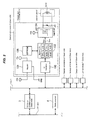
- Fig. 2 illustrates an internal constitution of the solenoid valve device, particularly, the internal constitution of the solenoid valve device 11 in the front air conditioner 10.
- the solenoid valve device 21 in the rear air conditioner 20 and the solenoid valve device 31 in the battery air conditioner 30 have same constitutions, so that the detailed explanation is omitted.
- the solenoid valve control device 13 in the solenoid valve device 11 is constituted by, for example, an electronic circuit board in which electronic components are soldered on a print board.
- the electronic circuit board is fixed to a resin case by screws, or the like, and the case is fixed to metal fittings attached to a coil 121 in the solenoid valve 12 by screws, or the like.
- the solenoid valve control device 13 is integrally fixed to the solenoid valve 12.
- the coil 121 in the solenoid valve 12 connects lead wires and the lead wires directly connect the print board in the solenoid valve control device 13 by, for example, soldering, or the like.
- the solenoid valve control device 13 in the solenoid valve device 11 connects a battery power supply (+Vb, GND), and also connects a LIN (Local Interconnect Network) bus 1 (or CAN (Controller Area Network) bus).
- the LIN is, for example, a vehicle LAN (Local Area Network) used in communication in the vehicle such as an automobile, or the like.
- the solenoid valve control device 13 in the solenoid valve device 11 operates as a slave node.
- the solenoid valve control device 13 periodically receives instructions such as signals indicating opening and closing of the solenoid valve 12 via LIN communication signals (CAN communication signals in a case of CAN bus) and controls opening and closing of the solenoid valve 12.
- the LIN communication signals are transmitted from an ECU (Electronic Control Unit) for the air conditioning system 3 (for example, a car air conditioner) which operates as a master node.
- ECU Electronic Control Unit
- the signal instructing opening and closing of the solenoid valve 12, which is received by the solenoid valve control device 13, is acceptable either a signal directly representing the opening and closing of the solenoid valve 12 or, for example, a signal representing energizing and de-energizing.
- the solenoid valve control device 13 receives the signal representing the energizing, for example, if the solenoid valve 12 is a normal open type, the solenoid valve 12 closes. If the solenoid valve 12 is a normal close type, the solenoid valve 12 opens.
- the solenoid valve control device 13 receives the signal representing the de-energizing, if the solenoid valve 12 is a normal open type, the solenoid valve 12 opens. If the solenoid valve 12 is a normal close type, the solenoid valve 12 closes.
- the air conditioning system 100 has, for example, damper devices 61 and 71 adjusting an air volume, other than the solenoid valves 11, 12, 13, and the like.
- the solenoid valve device 11 On the LIN bus 1 in which the solenoid valve device 11 is connected, the solenoid valve device 21 and the solenoid device 31 which operate as a slave node used in the air conditioning system, the damper devices 61 and 71, and the like, are connected.
- the ECU for air conditioning system 3 (for example, a car air conditioner), which operates as a master node, is connected to CAN bus 2 which is used as communication in the vehicle.
- the ECU for air conditioning system 3 can communicate with other ECU not illustrated, testing equipment, and a display device 4 such as a navigation screen, a control panel, or the like, of the vehicle.
- the testing equipment connects the vehicle at a time of maintenance service.
- the solenoid valve control device 13 mainly includes a regulator 131, a LIN transceiver 132, a microcomputer 133, an IPD (Intelligent Power Device) 134, a FWD (Free Wheeling Diode) 135, and an EEPROM (Electrically Erasable Programmable Read-Only Memory) 136.
- IPD Intelligent Power Device
- FWD Free Wheeling Diode
- EEPROM Electrically Erasable Programmable Read-Only Memory
- the regulator 131 generates a power supply +Vc (for example, +5 Vdc) used in an internal circuit of the solenoid valve control device 13 from a power supply +Vb (for example, +12 Vdc) of the battery of the vehicle connected to the solenoid valve control device 13.
- +Vc for example, +5 Vdc
- +Vb for example, +12 Vdc
- the LIN transceiver (transmitting and receiving unit) 132 is connected to LIN bus 1 and converts a voltage level of the LIN bus 1 to a voltage level of the internal circuit in the solenoid valve control device 13.
- the LIN transceiver 132 can make, for example, to perform LIN communication between the ECU for air conditioning system 3 and the microcomputer 133.
- the microcomputer 133 is connected to the LIN transceiver 132 and has ROM, CPU, RAM, an I/O circuit, a timer, a A/D convertor, and the like.
- the ROM stores programs, or the like, controlling the opening and closing of the solenoid valve 12 based on the LIN communication signal transmitted from the ECU for air conditioning system 3 via the LIN bus 1.
- the CPU performs execution processing of the programs stored in the ROM and calculation processing of the number of operations of the solenoid valve 12, or the like.
- the RAM temporally stores the number of operations of the solenoid valve 12, or the like, calculated in the CPU.
- the I/O circuit performs input/output processing with the peripheral circuits containing an output port Psv outputting a control signal Ssv of the solenoid valve 12.
- the timer measures times.
- the A/D convertor converts an analog voltage to a digital value.
- the IPD 134 connects the output port Pvs of the microcomputer 133 and contains, for example, a switching element such as MOSFET (Metal Oxide Semiconductor Field Effect Transistor), or the like.
- the IPD 134 controls an energized state of the battery voltage applying to the solenoid valve 12 based on the control signal Ssv of the solenoid valve 12 output from the output port Psv in the microcomputer 133.
- the FWD 135 connects the coil 121 of the solenoid valve 12 in parallel, and refluxes the load current, for example, when MOSFET is OFF.
- the EEPROM (storage unit) 136 which is a non-volatile memory, connects the microcomputer 133 and stores data of the number of operations, or the like, which is necessary to retain when the power supply of the battery is disconnected, in the data stored in the microcomputer 133.
- the regulator 131, the LIN transceiver 132, the microcomputer 133, the IPD 134, the FWD 135, and the EEPROM 136 may be constituted independently each other, and an IC chip, in which two or more of them are integrated, may be used to reduce the size of the solenoid valve control device 13.
- the control processing of the solenoid valve 12 by the solenoid valve control device 13 will be outlined.
- the ECU for air conditioning system 3 transmits a signal indicating the opening and closing or energizing and de-energizing of the solenoid valve 12 to the solenoid valve control device 13 by the LIN communication signal via the LIN bus 1.
- the operation is performed base on a condition of the vehicle or a switch operation by a driver.
- the solenoid valve control device 13 receives the LIN communication signal transmitted from the ECU for air conditioning system 3 by the LIN transceiver 132.
- the LIN transceiver 132 converts the voltage level of the LIN communication signal to the voltage level of the internal circuit of the solenoid valve control device 13 and outputs the signal to the microcomputer 133.
- the microcomputer 133 inputs the signal and outputs the control signal Ssv, which corresponds to the opening and closing, or the energizing and de-energizing of the solenoid valve 12, to the IPD 134 from the output port Psv.
- the IPD 134 controls the energized condition of the battery voltage +Vb (for example, +12Vdc) based on the control signal Ssv input from the output port Psv in the microcomputer 133, and controls the opening and closing, or the energizing and de-energizing of the solenoid valve 12.
- the microcomputer 133 counts the number of operations, such as the number of times of opening, the number of times of closing, and the number of times of energizing, and outputs the data to the EEPROM 136.
- the EEPROM 136 stores the number of operations.
- Fig. 3 illustrates an example of the control signal output from the microcomputer 133 in the solenoid valve control device 13 illustrated in Fig. 2 , in time series.
- the solenoid valve 12 is the normal close type
- an example of the control signal Ssv controlling the energized state of the battery voltage +Vb is illustrated.
- the battery voltage +Vb is output from the output port Psv in the microcomputer 133 based on the LIN communication signal indicating the opening and closing of the solenoid valve 12, and then applied to the coil 121 of the solenoid valve 12.
- the LIN communication signal is receive from the ECU for air conditioning system 3 by the solenoid valve control device 13.
- the control signal Ssv of the solenoid valve 12 output from the output port Psv becomes H (High).
- the IPD134 inputting the control signal Ssv makes the switching element, for example, MOSFET, or the like, to be ON and applies the battery voltage to the solenoid valve 12, so that the solenoid valve 12 becomes an energized state and opens.
- the control signal Ssv of the solenoid valve 12 output from the output port Psv becomes L (Low).
- the IPD134 inputting the control signal Ssv makes the switching element, for example, MOSFET, or the like, to be OFF and does not apply the battery voltage to the solenoid valve 12, so that the solenoid valve 12 becomes a de-energized state and closes.
- the switching element for example, MOSFET, or the like
- the microcomputer 133 receives the LIN communication signal indicating the closing of the solenoid valve 12 from the ECU for air conditioning system 3.
- the microcomputer 133 sets the output port Psv to be 0, and the control signal Ssv of the solenoid valve 12, which is output from the output port Psv, becomes L.
- the IPD 134 makes the switching element to be OFF and does not apply the battery voltage to the solenoid valve 12, so that the solenoid valve 12 becomes the de-energized state and closes.
- the microcomputer 133 receives the LIN communication signal indicating the opening of the solenoid valve 12 from the ECU for air conditioning system 3.
- the microcomputer 133 sets the output port Psv to be 1, and the control signal Ssv of the solenoid valve 12, which is output from the output port Psv, becomes H.
- the IPD 134 makes the switching element to be ON and applies the battery voltage to the solenoid valve 12, so that the solenoid valve 12 becomes the energized state and opens.
- the microcomputer 133 controls the ON/OF operation of the switching element, such as MOSFET in the IPD 134, and controls the battery voltage applying to the solenoid valve 12 and decreases the current flowing to the coil 121 of the solenoid valve 12. By this operation, the temperature rise can be inhibited.
- the switching element such as MOSFET in the IPD 134
- the solenoid valve 12 when the solenoid valve 12 is a normal open type, the solenoid valve 12 closes in the energized state and opens in the de-energized state.
- the LIN communication signal received from the ECU for air conditioning system 3 by the solenoid valve control device 13 can be a signal indicating the energizing or de-energizing of the solenoid valve 12.
- the microcomputer 133 in the solenoid valve control device 13 counts the number of operations.
- the number of operations are, for example, in the time range t1 to t6 illustrated in Fig. 3 , the number of times of opening (for example, 2 times), the number of times of closing (for example, 3 times), the number of times of energizing (for example, 2 times) of the solenoid valve 12, and the like.
- the microcomputer 133 outputs these data to the EEPROM 136.
- the EEPROM 136 stores the number of operations of the solenoid valve 12 output from the microcomputer 133.
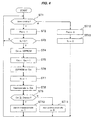
- Fig. 4 is a flow chart explaining a processing flow of the microcomputer in the solenoid valve control device 13 illustrated in Fig. 2 . Particularly, when the solenoid valve 12 is the normal close type, the flow chart explains control processing flow of the opening and closing of the solenoid valve 12 by the microcomputer 133 in the solenoid valve control device 13.
- step ST 1 the microcomputer 133 determines whether the periodical LIN communication signal (for example, at every 200 msec) received from the ECU for air conditioning system 3 is the signal indicating the opening of the solenoid valve 12.
- the processing proceeds to step ST 2.
- step ST 2 the microcomputer 133 sets the output port Psv to be 1 and makes the control signal Ssv of the solenoid valve 12 to be H. Then, the microcomputer 133 makes the switching element, for example, MOSFET, or the like, in the IPD 134 to be ON and applies the battery voltage to the solenoid valve 12. The microcomputer 133 energizes in the solenoid valve 12 and opens the solenoid valve 12.
- step ST 3 the microcomputer 133 determines whether a count flag fc is 0.
- the count flag fc is the flag indicating the count of number of operations of the solenoid valve 12.
- the count flag fc is 0, the operations of the solenoid valve 12 (opening operation) are not counted.
- the count flag fc is 1, the operations of the solenoid valve 12 are already counted and the initial value of the count flag fc is 0.
- the microcomputer does not count the operations of the solenoid valve 12 in step ST 2, that is, the count flag fc is 0 which is the initial value, the processing proceeds to step ST 4.
- the processing returns to ST 1.
- the microcomputer 133 inhibits to count again the number of operations of the solenoid valve 12 in step ST 2, in which the microcomputer 133 already counts.
- step ST 4 the microcomputer 133 reads a number of operations counter Cm stored in the EEPROM 133.
- step ST 5 the microcomputer 133 adds 1 to the number of operations counter Cm on the RAM (for example, when the operation of the solenoid valve 12 is the first, the number of operations counter Cm is 1).
- step ST 6 the microcomputer 133 writes a new number of operations counter Cm on the RAM in the EEPROM 136 again and stores.
- the solenoid valve control device 13 can store the number of operations of the solenoid valve 12, which affects the durability.
- the microcomputer 133 stores the number of operations of the solenoid valve 12 stores in the EEPROM 136, which is the non-volatile memory.
- the microcomputer 133 can reliably store the number of operations of the solenoid valve 12. In addition to this, even when the microcomputer 133 does not operate by cutting off the power supply +Vc, the microcomputer 136 can reliably store the number of operations of the solenoid valve 12. Furthermore, even when the battery power supply +Vb of the solenoid valve control device 13 is cut off, the microcomputer 133 can reliably store the number of operations of the solenoid valve 12.
- step ST 8 since the microcomputer has counted the number of operations by the opening operation of the solenoid valve 12, the microcomputer sets the count flag fc to be 1.
- step ST 8 in order to transmit the number of operations of the solenoid valve 12 counted in step ST 5 from the microcomputer 133 to, for example, the ECU for air conditioning system 3, the microcomputer 133 sets the number of operations counter Cm on the RAM in a transmission buffer resistor for the LIN communication.
- the transmission buffer resister is on the RAM similar to the number of operations counter Cm.
- the external ECU operating as a master node which receives the content of the transmission buffer resistor, can grasp the number of operations of the solenoid valve 12.
- a user such as a vehicle maintenance person, a driver, or the like, can confirms the number of operations of the solenoid valve 12 via a display device 4.
- the display device 4 is, for example, a display screen or a display lamp of the testing equipment connected to the vehicle, a navigation screen of the vehicle, a lamp on a control panel, or the like.
- the user can perform judgment of replacement of the solenoid valve 12, before the number of operations of the solenoid valve 12 becomes equal to or greater than the limitation number of times concerning the life of the solenoid valve 12.
- the limitation number of times of the solenoid valve 12 concerning the life of the solenoid valve 12 can be previously stored in, for example, the microcomputer 133, or the like.
- the limitation number of times of the solenoid valve 12 can be stored after calculating by the microcomputer 133, or the like, according to the usage environment of the vehicle, in which the air conditioning system 100 is mounted.
- the user himself can arbitrarily set the limitation number of times of the solenoid valve 12.
- step ST 9 the microcomputer 133 determines whether the number of operations counter Cm on the RAM in the microcomputer 133 is equal to or greater than the limitation number of times concerning the life of the solenoid valve 12 (hereinafter, referred to as the number of operations limitation value) Cmmax (for example, 100, 000 times).
- the microcomputer 133 determines that the number of operations counter Cm is equal to or greater than the number of operations limitation value Cmmax, the microcomputer 133 determines that the number of operations of the solenoid valve 12 is equal to or greater than the number of operations acceptable on the durability of the solenoid valve 12. Then, the processing proceeds to step ST 10 and the microcomputer 133 sets an alarm bit to be 1.
- the microcomputer 133 receives, for example, the transmission requirement signal from the ECU for air conditioning system 3 by the LIN communication via the LIN bus 1, the microcomputer 133 transmits the content of the transmission buffer resistor to the ECU for air conditioning system 3 via the LIN bus 1 as the LIN communication signal.
- the external ECU operating as the master node can grasp that the number of operations of the solenoid valve 12 is equal to or greater than the number of operations acceptable on the durability of the solenoid valve 12.
- the external ECU transmits the alarm signal indicating the message, that the solenoid valve is at the time to replace, to the display equipment 4 at a time of, for example, a periodic maintenance service.
- the display equipment 4 is, for example, a display screen or a display lamp of the testing equipment connected to the vehicle, a navigation screen of the vehicle, a lamp on a control panel, or the like.
- the external ECU promotes the necessity of the maintenance of the solenoid valve to a user such as a vehicle maintenance person, a driver, or the like, via the display devices 4.
- the user can promptly replace the solenoid valve 12, which is equal to or greater than the number of operations acceptable on the durability, to a new solenoid valve.
- the microcomputer 133 determines that the solenoid valve 12 is in a normal state and the processing proceeds to step ST 11. Then, the microcomputer 133 clears the alarm bit of the transmission buffer resistor to be 0.
- step S 11 when the LIN communication signal received from the ECU for air conditioning system 3 is the signal indicating the opening of the solenoid valve 12, the microcomputer 133 in the solenoid valve control device 13 repeats these processing. By repeating these processing, the microcomputer 133 in the solenoid valve control device 13 can preciously count the number of operations, which affects the durability of the solenoid valve 12, and store them.
- step ST 1 the microcomputer 133 determines whether the periodic LIN communication signal received from the ECU for air conditioning system 3 is the signal indicating the opening of the solenoid valve 12.
- the processing proceeds to step ST 12.
- step ST 12 the microcomputer 133 sets the output port Psv to be 0 and makes the control signal Ssv of the solenoid valve 12 to be L. Further, the microcomputer 133 makes the switching element of the IPD 134, for example, MOSFET, or the like, to be OFF and does not apply the battery voltage to the solenoid valve 12, so that the solenoid valve 12 becomes de-energized state and closes. Then, in step ST 13, the microcomputer 133 clears the count flag fc to be 0 and ends the processing.
- the switching element of the IPD 134 for example, MOSFET, or the like
- step ST 1 the microcomputer 133 determines whether the LIN communication signal received from ECU for air conditioning system 3 is the signal indicating the opening of the solenoid valve 12.
- the processing proceeds to step 2, and the solenoid valve control device 13 counts the number of operations of the solenoid valve 12 and stores them.
- Fig. 5 is illustrates an example of the above transmission buffer resistor.
- the buffer resistor which sets the number of operations counter Cm of the solenoid valve 12
- the buffer resistor is set to be 17 bits.
- the alarm bit of the buffer resistor is set to be 1 bit and the number of operations limitation value Cmmax of the solenoid valve 12 is set to be 100,000 times.
- the number of operations of the solenoid valve 12 is less than 100,000 times, 0 which indicates normal is set in the alarm bit of the buffer resistor.
- the number of operations of the solenoid valve 12 is equal to or greater than 100,000 times, 1 which indicates alarm is set in the alarm bit of the buffer resistor. That is, when the number of operations limitation value Cmmax of the solenoid valve 12 is 100,000 times, the transmission buffer resistor is composed of, for example, 18 bits as illustrated in Fig. 5 .
- the air conditioning system 100 of the present exemplary embodiment includes the front air conditioner 10, the rear air conditioner 20, and the battery air conditioner 30, as illustrated in Fig. 1 .
- Each air conditioner uses the solenoid valve 12, the solenoid valve 22, and the solenoid valve 32.
- the following settings can be done independently to the solenoid valve 12, the solenoid valve 22, and the solenoid valve 32.
- the output port Psv of the microcomputer 133 is set as Psv 1
- the control signal Ssv of the solenoid valve 12 is set as Ssv 1
- the count flag Fc is set as fc 1
- the number of operations counter Cm is set as Cm 1
- the transmission buffer resistor is set as a transmission resistor 1
- the number of operations limitation value Cmmax is set as Cmmax 1
- the alarm bit of the transmission buffer resistor is set as a alarm bit 1.
- the output port Psv of the microcomputer 133 is set as Psv 2
- the control signal Ssv of the solenoid valve 22 is set as Ssv 2
- the count flag fc is set as fc 2
- the number of operations counter Cm is set as Cm 2
- the transmission buffer resistor is set as a transmission resistor 2
- the number of operations limitation value Cmmax is set as Cmmax 2
- the alarm bit of the transmission buffer resistor is an alarm bit 2.
- the output port Psv of the microcomputer 133 is set as Psv 3
- the control signal Ssv of the solenoid valve 32 is set as Ssv 3
- the count flag fc is set as fc 3
- the number of operations counter Cm is set as Cm 3
- the transmission buffer resistor is set as a transmission resistor 3
- the number of operations limitation value Cmmax is set as Cmmax 3
- the alarm bit of the transmission buffer resistor is an alarm bit 3.
- the number of bits of the above transmission buffer resister and its alarm bit can be changed arbitrarily and may be indicated by which 0 of the alarm bit is alarm and 1 of the alarm bit is normal.
- the following constitutions are described. That is, when the control signal Ssv of the solenoid valve becomes H (high), the switching element of the IPD, for example, MOSFET, or the like, becomes ON and the battery voltage is applied to the solenoid valve to be energized in the solenoid valve. When the control signal Ssv of the solenoid valve becomes L (Low), the switching element of the IPD, for example, MOSFET, or the like, becomes OFF and the battery voltage is not applied to the solenoid valve to be de-energized in the solenoid valve.
- the following constitutions may be acceptable.
- the switching element becomes ON and the battery voltage is applied to the solenoid valve to be energized.
- the control signal Ssv in the solenoid valve becomes H, the switching element becomes OFF and the battery voltage is not applied to the solenoid valve to be de-energized.
- the microcomputer 133 in the solenoid valve device 11 transmits the number of operations of the solenoid valve 12 to the ECU for air conditioning system 3 via the LIN bus 1 and then, transmits from the ECU for air conditioning system 3 to the display equipment 4 via CAN bus 2.
- the microcomputer 133 may transmit the number of operations of the solenoid valve 12 to an ECU other than the ECU for air conditioning system 3 via LIN bus 1 and then, transmit from the ECU to the display equipment 4.
- the display equipment 4 connects the LIN bus 1 and the microcomputer 133 can directly transmit the number of operations of the solenoid valve 12 ton the display equipment 4 via the LIN bus 1.
- the microcomputer 133 stores mainly the number of operations of the opening operation of the solenoid valve as the number of operations concerning the opening and closing of the solenoid valve.
- the number of closing of the solenoid valve or the number of energizing to the solenoid valve may be the number of operations concerning the opening/closing of the solenoid valve.
- the arbitrary combination number of times of the opening, closing, and energizing of the solenoid valve may be the number of operations concerning the opening/closing of the solenoid valve.
- the limitation number of times concerning the life of the solenoid valve for generating the alarm signal is the number of operations acceptable on the durability of the solenoid valve (for example, 100,000 times).
- the maximum number of operations of the solenoid valve writable in the transmission buffer resistor for transmitting the number of operations of the solenoid valve may be the limitation number of times concerning the life of the solenoid valve.
- the maximum number of operations of the solenoid valve storable in the EEPROM which is a storage unit, may be the limitation number of times concerning the life of the solenoid valve.
- a first limitation number of times concerning the life of the solenoid valve and a second limitation number of times concerning the life of the solenoid valve may be set.
- the first limitation number of times is the number of operations acceptable on the durability of the solenoid valve (for example, 100,000 times).
- the second limitation number of times is the maximum number of operations of the solenoid valve writable in the transmission buffer resistor for transmitting the number of operations of the solenoid valve (for example, 131,071 times), or the maximum number of operations of the solenoid valve storable in the EEPROM.
- the embodiment, in which the IPD internally having the switching element such as MOSFET, or the like, is used as a device driving the solenoid valve is described.
- a single MOSFET may be used as the device driving the solenoid valve.
- a bipolar transistor, an insulated gate bipolar transistor (IGBT), a relay, and a solid state relay (SSR) may be used as the device driving the solenoid valve.
Landscapes
- Engineering & Computer Science (AREA)
- General Engineering & Computer Science (AREA)
- Mechanical Engineering (AREA)
- Magnetically Actuated Valves (AREA)
Abstract
Description
- The present invention relates to a solenoid valve control device, for example, a control device of a solenoid valve used in an air conditioning system for vehicles.
- For example, in an air conditioning system for vehicles having a front air conditioner and a rear air conditioner, a solenoid valve controlling a flow of a refrigerant to the front air conditioner and a solenoid valve controlling a flow of a refrigerant to the rear air conditioner are used. Generally, when the front air conditioner is used, the solenoid valve for the front air conditioner opens to pass the refrigerant to the front air conditioner. When the front air conditioner is not used, the solenoid valve for the front air conditioner closes to stop the flow of the refrigerant to the front air conditioner. Further, when the rear air conditioner is used, the solenoid valve for the rear air conditioner opens to pass the refrigerant to the rear air conditioner. When the rear air conditioner is not used, the solenoid valve for the rear air conditioner closes to stop the flow of the refrigerant to the rear air conditioner (for example, Japanese Patent Application Laid-Open, No.
7-117455 - Further, in the solenoid valve used in the above air conditioning system, there are two types, which are a normal open type and a normal close type. The solenoid valve of the normal open type opens in a de-energized state and closes by operating the valve when in an energized state. On the other hand, the solenoid valve of the normal close type closes in a de-energized state and opens by operating the valve when in an energized state.
- By the way, the above solenoid valve has a life of durability since it is a mechanical part, so that limitation of number of operations, for example, 100,000 times, is provided.
- Therefore, for example, when the solenoid valve of the normal close type is used in an air conditioning system of vehicles is used and overs the limitation of number of times (for example, 100,000 times) concerning the life of number of operations of the solenoid valve before a guarantee period of the vehicle has expired, some problems generate. For examples, even when energizing the solenoid valve, the valve does not open and stays in a closed state, so that the valve cannot perform air conditioning in the vehicle. Even when de-energizing, the valve does not close and stays in an opening state, so that the valve cannot stop the flow of the refrigerant. Further, when the solenoid valve of the normal open type is used in the air conditioning system of vehicles and overs the limitation of number of times (for example, 100,000 times) concerning the life of number of operations of the solenoid valve before the guarantee period of the vehicle has expired, some problems generate. For example, even when energizing the solenoid valve, the valve does not close and stays in the opening state, so that the valve cannot stop the flow of the refrigerant. Even when de-energizing, the solenoid valve does not open and stays in the closing state, so that the valve cannot perform air conditioning in the vehicle.
- For solving these problems, Japanese Patent No.
4431996 - A drive circuit of the solenoid valve disclosed in Japanese Patent No.
4431996 - According to the drive circuit of the solenoid valve disclosed in Japanese Patent No.
4431996 - However, according to the drive circuit of the solenoid valve disclosed in Japanese Patent No.
4431996 - The present invention was conceived in view of above problems, and is directed to provide a solenoid valve control device, in which a user, or the like, can preciously grasps the state of the solenoid valve based on the number of operations.
- For solving the above problem, a solenoid valve control device according to the present invention is a solenoid valve control device controlling a solenoid valve, and includes a storage unit storing the number of operations concerning opening/closing of the solenoid valve and a transmission unit externally transmitting the number of operations stored in the storage unit.
- In a preferable embodiment, when the number of operations stored in the storage unit overs the limitation number of times concerning the life of the solenoid valve, the transmission unit externally outputs an alarm signal. Further, in a preferable embodiment, the limitation number of times is the number of operations acceptable on durability of the solenoid valve. Further, in a preferable embodiment, the number of operations is any one of the number of times of opening, the number of times of closing, and the number of times of energizing of the solenoid valve. Further, in a preferable embodiment, the transmission unit externally transmits by a local interconnect network (LIN) communication or a controller area network (CAN) communication. Further, in a preferable embodiment, the storage unit is a non-volatile memory.
- According to the solenoid valve of the present invention, the transmission unit externally transmits the number of operations concerning the solenoid valve, and thereby the user, or the like, can preciously grasp the number of operations of opening/closing of the solenoid valve at a desired time. Further, when the number of operations stored in the storage unit becomes equal to or greater than the limitation number of times concerning the life of the solenoid valve, parkicularly, equal to or greater than the number of operations acceptable on durability of the solenoid valve, the transmission unit externally transmits the alarm signal. By this operation, the user can reliably grasp that the solenoid valve is at the time of replacement. Further, since the number of operations is any one of the number of times of opening, number of times of closing, and number of times of energizing of the valve, the user can preciously grasp the number of operations concerning the opening/closing of the solenoid valve. Further, since the transmission unit externally communicates by the LIN communication or the CAN communication which are conventionally used in vehicles, or the like, the solenoid valve control device is simply applicable to the air conditioning system for vehicles (car air conditioner) without building a new communication network. Further, since the storage unit is a non-volatile memory, the solenoid valve control device can reliably store the number of operations of the solenoid valve in the storage unit, even when the solenoid valve control device operates in a sleep mode reducing power consumption, or power supply of the solenoid valve control device is stopped.
-
-
Fig. 1 is an overall block diagram explaining a refrigeration cycle of an air conditioning system in which a solenoid valve control device according to the present invention is adapted. -
Fig. 2 is an internal block diagram illustrating an internal constitution of the solenoid valve device illustrated inFig. 1 . -
Fig. 3 is a view illustrating an example of a control signal outputting from a microcomputer in the solenoid valve control device illustrated inFig. 2 , by showing time series. -
Fig. 4 is a flow chart explaining a flow of processing of the microcomputer in the solenoid valve control device illustrated inFig. 2 . -
Fig. 5 is a view illustrating an example of a transmission buffer resister. - The exemplary embodiment of the solenoid valve control device according to the present invention will be described, referring to drawings as follows.
-
Fig. 1 explains a refrigeration cycle of the air conditioning system in which a solenoid valve control device according to the present invention is adapted. For example,Fig. 1 explains a cooling cycle of the air conditioning system for an electric vehicle mounting a battery. In addition, an arrow inFig. 1 indicates a flow direction of refrigeration at a time of cooling. - The
air conditioning system 100 illustrated inFig. 1 (for example, a car air conditioner) includes afront air conditioner 10, arear air conditioner 20, a battery air conditioner, acompressor 40, and acondenser 50. These equipment are connected each other by piping and a refrigeration circulates in them, so that the refrigeration cycle is constituted. - The
front air conditioner 10 is used, for example, for air conditioning of the front seats in a vehicle interior and includes asolenoid valve device 11, anexpansion valve 15, and anevaporator 16. Further, thesolenoid valve device 11 has a structure in which a solenoidvalve control device 13 for controlling the opening/closing of asolenoid valve 12 is integrally attached to thesolenoid valve 12. - Further, the
rear air conditioner 20 is used, for example, for air conditioning of the rear seats in the vehicle interior and includes asolenoid valve device 21, anexpansion valve 25, and anevaporator 26. Further, thesolenoid valve device 21 has a structure in which a solenoidvalve control device 23 for controlling the opening/closing of asolenoid valve 22 is integrally attached to thesolenoid valve 22. - Further, the
battery air conditioner 30 is used, for example, for cooling a battery mounted in a vehicle and includes asolenoid valve device 31, anexpansion valve 35, and anevaporator 36. Further, thesolenoid valve device 31 has a structure in which a solenoidvalve control device 33 for controlling the opening/closing of a solenoid valve 32 is integrally attached to the solenoid valve 32. - For example, by opening the
solenoid valve 12 by the solenoidvalve control device 13 in thesolenoid valve device 11 in thefront air conditioner 10, the refrigerant flows to theevaporator 16 through thesolenoid valve 12 and theexpansion valve 15, so that the front seats in the vehicle interior can be cooled. Further, by opening thesolenoid valve 22 by the solenoidvalve control device 23 in thesolenoid valve device 21 in therear air conditioner 20, the refrigerant flows to theevaporator 26 through thesolenoid valve 22 and theexpansion valve 25, so that the rear seats in the vehicle interior can be cooled. Furthermore, by opening thesolenoid valve 22 by the solenoidvalve control device 23 in thesolenoid valve device 31 in thebattery air conditioner 30, the refrigerant flows to theevaporator 36 through the solenoid valve 32 and theexpansion valve 35, so that the battery mounted in the vehicle can be cooled. - On the other hand, when the solenoid
valve control device 33 in thesolenoid valve device 31 in the battery air conditioner closes the solenoid valve 32, the flow of the refrigerant flowing to theevaporator 36 through the solenoid valve 32 and theexpansion valve 35 is blocked. Thus, for example, when the cooling of the battery mounted in the vehicle is not necessary, it is possible not to perform the cooling of the battery in theair conditioning system 100. Further, when the solenoidvalve control device 13 in thesolenoid valve device 11 in thefront air conditioner 10 closes thesolenoid valve 12 and the solenoidvalve control device 23 in thesolenoid valve device 21 in therear air conditioner 20 closes thesolenoid valve 22, the following flows of the refrigerant are blocked. That is, the flow of the refrigerant flowing toevaporator 16 through thesolenoid valve 12 and theexpansion valve 15 is blocked by closing thevalve 12, and the flow of the refrigerant flowing to theevaporator 26 through thesolenoid valve 22 and theexpansion valve 25 is blocked by closing thesolenoid valve 22. Thus, for example, when a rider stops a vehicle and leaves from the vehicle to perform only charge, it is possible not to perform the air conditioning of the front seats and the rear seats. -
Fig. 2 illustrates an internal constitution of the solenoid valve device, particularly, the internal constitution of thesolenoid valve device 11 in thefront air conditioner 10. In addition, thesolenoid valve device 21 in therear air conditioner 20 and thesolenoid valve device 31 in thebattery air conditioner 30 have same constitutions, so that the detailed explanation is omitted. - The solenoid
valve control device 13 in thesolenoid valve device 11 is constituted by, for example, an electronic circuit board in which electronic components are soldered on a print board. The electronic circuit board is fixed to a resin case by screws, or the like, and the case is fixed to metal fittings attached to acoil 121 in thesolenoid valve 12 by screws, or the like. Thus, the solenoidvalve control device 13 is integrally fixed to thesolenoid valve 12. Further, thecoil 121 in thesolenoid valve 12 connects lead wires and the lead wires directly connect the print board in the solenoidvalve control device 13 by, for example, soldering, or the like. - Further, the solenoid
valve control device 13 in thesolenoid valve device 11 connects a battery power supply (+Vb, GND), and also connects a LIN (Local Interconnect Network) bus 1 (or CAN (Controller Area Network) bus). The LIN is, for example, a vehicle LAN (Local Area Network) used in communication in the vehicle such as an automobile, or the like. The solenoidvalve control device 13 in thesolenoid valve device 11 operates as a slave node. The solenoidvalve control device 13 periodically receives instructions such as signals indicating opening and closing of thesolenoid valve 12 via LIN communication signals (CAN communication signals in a case of CAN bus) and controls opening and closing of thesolenoid valve 12. The LIN communication signals are transmitted from an ECU (Electronic Control Unit) for the air conditioning system 3 (for example, a car air conditioner) which operates as a master node. - Here, the signal instructing opening and closing of the
solenoid valve 12, which is received by the solenoidvalve control device 13, is acceptable either a signal directly representing the opening and closing of thesolenoid valve 12 or, for example, a signal representing energizing and de-energizing. When the solenoidvalve control device 13 receives the signal representing the energizing, for example, if thesolenoid valve 12 is a normal open type, thesolenoid valve 12 closes. If thesolenoid valve 12 is a normal close type, thesolenoid valve 12 opens. On the other hand, when the solenoidvalve control device 13 receives the signal representing the de-energizing, if thesolenoid valve 12 is a normal open type, thesolenoid valve 12 opens. If thesolenoid valve 12 is a normal close type, thesolenoid valve 12 closes. - In addition, the
air conditioning system 100 has, for example,damper devices solenoid valves LIN bus 1 in which thesolenoid valve device 11 is connected, thesolenoid valve device 21 and thesolenoid device 31 which operate as a slave node used in the air conditioning system, thedamper devices CAN bus 2 which is used as communication in the vehicle. The ECU forair conditioning system 3 can communicate with other ECU not illustrated, testing equipment, and adisplay device 4 such as a navigation screen, a control panel, or the like, of the vehicle. The testing equipment connects the vehicle at a time of maintenance service. - The solenoid
valve control device 13 mainly includes aregulator 131, aLIN transceiver 132, amicrocomputer 133, an IPD (Intelligent Power Device) 134, a FWD (Free Wheeling Diode) 135, and an EEPROM (Electrically Erasable Programmable Read-Only Memory) 136. - The
regulator 131 generates a power supply +Vc (for example, +5 Vdc) used in an internal circuit of the solenoidvalve control device 13 from a power supply +Vb (for example, +12 Vdc) of the battery of the vehicle connected to the solenoidvalve control device 13. - The LIN transceiver (transmitting and receiving unit) 132 is connected to
LIN bus 1 and converts a voltage level of theLIN bus 1 to a voltage level of the internal circuit in the solenoidvalve control device 13. TheLIN transceiver 132 can make, for example, to perform LIN communication between the ECU forair conditioning system 3 and themicrocomputer 133. - The
microcomputer 133 is connected to theLIN transceiver 132 and has ROM, CPU, RAM, an I/O circuit, a timer, a A/D convertor, and the like. The ROM stores programs, or the like, controlling the opening and closing of thesolenoid valve 12 based on the LIN communication signal transmitted from the ECU forair conditioning system 3 via theLIN bus 1. The CPU performs execution processing of the programs stored in the ROM and calculation processing of the number of operations of thesolenoid valve 12, or the like. The RAM temporally stores the number of operations of thesolenoid valve 12, or the like, calculated in the CPU. The I/O circuit performs input/output processing with the peripheral circuits containing an output port Psv outputting a control signal Ssv of thesolenoid valve 12. The timer measures times. The A/D convertor converts an analog voltage to a digital value. - The IPD 134 connects the output port Pvs of the
microcomputer 133 and contains, for example, a switching element such as MOSFET (Metal Oxide Semiconductor Field Effect Transistor), or the like. The IPD 134 controls an energized state of the battery voltage applying to thesolenoid valve 12 based on the control signal Ssv of thesolenoid valve 12 output from the output port Psv in themicrocomputer 133. - The FWD 135 connects the
coil 121 of thesolenoid valve 12 in parallel, and refluxes the load current, for example, when MOSFET is OFF. - The EEPROM (storage unit) 136, which is a non-volatile memory, connects the
microcomputer 133 and stores data of the number of operations, or the like, which is necessary to retain when the power supply of the battery is disconnected, in the data stored in themicrocomputer 133. - In addition, the
regulator 131, theLIN transceiver 132, themicrocomputer 133, the IPD 134, the FWD 135, and theEEPROM 136 may be constituted independently each other, and an IC chip, in which two or more of them are integrated, may be used to reduce the size of the solenoidvalve control device 13. - Then, the control processing of the
solenoid valve 12 by the solenoidvalve control device 13 will be outlined. At first, the ECU forair conditioning system 3 transmits a signal indicating the opening and closing or energizing and de-energizing of thesolenoid valve 12 to the solenoidvalve control device 13 by the LIN communication signal via theLIN bus 1. The operation is performed base on a condition of the vehicle or a switch operation by a driver. - The solenoid
valve control device 13 receives the LIN communication signal transmitted from the ECU forair conditioning system 3 by theLIN transceiver 132. TheLIN transceiver 132 converts the voltage level of the LIN communication signal to the voltage level of the internal circuit of the solenoidvalve control device 13 and outputs the signal to themicrocomputer 133. Themicrocomputer 133 inputs the signal and outputs the control signal Ssv, which corresponds to the opening and closing, or the energizing and de-energizing of thesolenoid valve 12, to the IPD 134 from the output port Psv. The IPD 134 controls the energized condition of the battery voltage +Vb (for example, +12Vdc) based on the control signal Ssv input from the output port Psv in themicrocomputer 133, and controls the opening and closing, or the energizing and de-energizing of thesolenoid valve 12. Themicrocomputer 133 counts the number of operations, such as the number of times of opening, the number of times of closing, and the number of times of energizing, and outputs the data to theEEPROM 136. TheEEPROM 136 stores the number of operations. -
Fig. 3 illustrates an example of the control signal output from themicrocomputer 133 in the solenoidvalve control device 13 illustrated inFig. 2 , in time series. Particularly, when thesolenoid valve 12 is the normal close type, an example of the control signal Ssv controlling the energized state of the battery voltage +Vb is illustrated. The battery voltage +Vb is output from the output port Psv in themicrocomputer 133 based on the LIN communication signal indicating the opening and closing of thesolenoid valve 12, and then applied to thecoil 121 of thesolenoid valve 12. The LIN communication signal is receive from the ECU forair conditioning system 3 by the solenoidvalve control device 13. - In the example, when the
microcomputer 133sets 1 on the output port Psv based on the LIN communication signal, the control signal Ssv of thesolenoid valve 12 output from the output port Psv becomes H (High). The IPD134 inputting the control signal Ssv makes the switching element, for example, MOSFET, or the like, to be ON and applies the battery voltage to thesolenoid valve 12, so that thesolenoid valve 12 becomes an energized state and opens. On the other hand, when themicrocomputer 133sets 0 on the output port Psv based on the LIN communication signal, the control signal Ssv of thesolenoid valve 12 output from the output port Psv becomes L (Low). The IPD134 inputting the control signal Ssv makes the switching element, for example, MOSFET, or the like, to be OFF and does not apply the battery voltage to thesolenoid valve 12, so that thesolenoid valve 12 becomes a de-energized state and closes. - As illustrated in
Fig. 3 , in the time ranges of, for example, t1 to t2, t3 to t4, and t5 to t6, themicrocomputer 133 receives the LIN communication signal indicating the closing of thesolenoid valve 12 from the ECU forair conditioning system 3. Themicrocomputer 133 sets the output port Psv to be 0, and the control signal Ssv of thesolenoid valve 12, which is output from the output port Psv, becomes L. At this time, the IPD 134 makes the switching element to be OFF and does not apply the battery voltage to thesolenoid valve 12, so that thesolenoid valve 12 becomes the de-energized state and closes. On the other hand, in the time ranges of t2 to t3 and t4 to t5, themicrocomputer 133 receives the LIN communication signal indicating the opening of thesolenoid valve 12 from the ECU forair conditioning system 3. Themicrocomputer 133 sets the output port Psv to be 1, and the control signal Ssv of thesolenoid valve 12, which is output from the output port Psv, becomes H. At this time, the IPD 134 makes the switching element to be ON and applies the battery voltage to thesolenoid valve 12, so that thesolenoid valve 12 becomes the energized state and opens. - In addition, when IPD 134 applies the battery voltage and makes to be the energized condition in the time range of, for example, t2 to t3 and t4 to t5, there is a case that temperature rise becomes a problem. In such a case, the
microcomputer 133 controls the ON/OF operation of the switching element, such as MOSFET in the IPD 134, and controls the battery voltage applying to thesolenoid valve 12 and decreases the current flowing to thecoil 121 of thesolenoid valve 12. By this operation, the temperature rise can be inhibited. - Further, as described above, when the
solenoid valve 12 is a normal open type, thesolenoid valve 12 closes in the energized state and opens in the de-energized state. Further, the LIN communication signal received from the ECU forair conditioning system 3 by the solenoidvalve control device 13, can be a signal indicating the energizing or de-energizing of thesolenoid valve 12. - Then, the
microcomputer 133 in the solenoidvalve control device 13 counts the number of operations. The number of operations are, for example, in the time range t1 to t6 illustrated inFig. 3 , the number of times of opening (for example, 2 times), the number of times of closing (for example, 3 times), the number of times of energizing (for example, 2 times) of thesolenoid valve 12, and the like. Then themicrocomputer 133 outputs these data to theEEPROM 136. TheEEPROM 136 stores the number of operations of thesolenoid valve 12 output from themicrocomputer 133. -
Fig. 4 is a flow chart explaining a processing flow of the microcomputer in the solenoidvalve control device 13 illustrated inFig. 2 . Particularly, when thesolenoid valve 12 is the normal close type, the flow chart explains control processing flow of the opening and closing of thesolenoid valve 12 by themicrocomputer 133 in the solenoidvalve control device 13. - At first, in
step ST 1, themicrocomputer 133 determines whether the periodical LIN communication signal (for example, at every 200 msec) received from the ECU forair conditioning system 3 is the signal indicating the opening of thesolenoid valve 12. When themicrocomputer 133 determines that the periodical LIN communication signal is the signal indicating the opening of thesolenoid valve 12, the processing proceeds to stepST 2. - Then, in
step ST 2, themicrocomputer 133 sets the output port Psv to be 1 and makes the control signal Ssv of thesolenoid valve 12 to be H. Then, themicrocomputer 133 makes the switching element, for example, MOSFET, or the like, in the IPD 134 to be ON and applies the battery voltage to thesolenoid valve 12. Themicrocomputer 133 energizes in thesolenoid valve 12 and opens thesolenoid valve 12. - Then, in
step ST 3, themicrocomputer 133 determines whether a count flag fc is 0. Here, the count flag fc is the flag indicating the count of number of operations of thesolenoid valve 12. When the count flag fc is 0, the operations of the solenoid valve 12 (opening operation) are not counted. When the count flag fc is 1, the operations of thesolenoid valve 12 are already counted and the initial value of the count flag fc is 0. When the microcomputer does not count the operations of thesolenoid valve 12 instep ST 2, that is, the count flag fc is 0 which is the initial value, the processing proceeds to stepST 4. In addition, when the microcomputer already counts the operations of thesolenoid valve 12 instep ST 2, that is, the count flag fc is 1, the processing returns toST 1. By this processing, themicrocomputer 133 inhibits to count again the number of operations of thesolenoid valve 12 instep ST 2, in which themicrocomputer 133 already counts. - Then, in
step ST 4, themicrocomputer 133 reads a number of operations counter Cm stored in theEEPROM 133. Instep ST 5, themicrocomputer 133 adds 1 to the number of operations counter Cm on the RAM (for example, when the operation of thesolenoid valve 12 is the first, the number of operations counter Cm is 1). Instep ST 6, themicrocomputer 133 writes a new number of operations counter Cm on the RAM in theEEPROM 136 again and stores. By this processing, the solenoidvalve control device 13 can store the number of operations of thesolenoid valve 12, which affects the durability. Further, themicrocomputer 133 stores the number of operations of thesolenoid valve 12 stores in theEEPROM 136, which is the non-volatile memory. Thus, even when themicrocomputer 133 enters in the sleep mode for making the solenoidvalve control device 13 to be in a power-saving state, themicrocomputer 133 can reliably store the number of operations of thesolenoid valve 12. In addition to this, even when themicrocomputer 133 does not operate by cutting off the power supply +Vc, themicrocomputer 136 can reliably store the number of operations of thesolenoid valve 12. Furthermore, even when the battery power supply +Vb of the solenoidvalve control device 13 is cut off, themicrocomputer 133 can reliably store the number of operations of thesolenoid valve 12. - Then, in
step ST 8, since the microcomputer has counted the number of operations by the opening operation of thesolenoid valve 12, the microcomputer sets the count flag fc to be 1. - Then, in
step ST 8, in order to transmit the number of operations of thesolenoid valve 12 counted instep ST 5 from themicrocomputer 133 to, for example, the ECU forair conditioning system 3, themicrocomputer 133 sets the number of operations counter Cm on the RAM in a transmission buffer resistor for the LIN communication. The transmission buffer resister is on the RAM similar to the number of operations counter Cm. When themicrocomputer 133 receives, for example, a transmission requirement signal from the ECU forair conditioning system 3 by the LIN communication via theLIN bus 1, themicrocomputer 133 transmits the content of the transmission buffer resistor to the ECU forair conditioning system 3 via theLIN bus 1 as the LIN communication signal. By this processing, the external ECU operating as a master node, which receives the content of the transmission buffer resistor, can grasp the number of operations of thesolenoid valve 12. Thus, at a time of a periodic maintenance service of a vehicle, such as an inspection of six months, an inspection of twelve months, a vehicle inspection, or the like, a user, such as a vehicle maintenance person, a driver, or the like, can confirms the number of operations of thesolenoid valve 12 via adisplay device 4. Thedisplay device 4 is, for example, a display screen or a display lamp of the testing equipment connected to the vehicle, a navigation screen of the vehicle, a lamp on a control panel, or the like. Thus, the user, or the like, can perform judgment of replacement of thesolenoid valve 12, before the number of operations of thesolenoid valve 12 becomes equal to or greater than the limitation number of times concerning the life of thesolenoid valve 12. In addition, the limitation number of times of thesolenoid valve 12 concerning the life of thesolenoid valve 12 can be previously stored in, for example, themicrocomputer 133, or the like. Further, the limitation number of times of thesolenoid valve 12 can be stored after calculating by themicrocomputer 133, or the like, according to the usage environment of the vehicle, in which theair conditioning system 100 is mounted. Furthermore, the user himself can arbitrarily set the limitation number of times of thesolenoid valve 12. - Then, in
step ST 9, themicrocomputer 133 determines whether the number of operations counter Cm on the RAM in themicrocomputer 133 is equal to or greater than the limitation number of times concerning the life of the solenoid valve 12 (hereinafter, referred to as the number of operations limitation value) Cmmax (for example, 100, 000 times). - Then, when the
microcomputer 133 determines that the number of operations counter Cm is equal to or greater than the number of operations limitation value Cmmax, themicrocomputer 133 determines that the number of operations of thesolenoid valve 12 is equal to or greater than the number of operations acceptable on the durability of thesolenoid valve 12. Then, the processing proceeds to stepST 10 and themicrocomputer 133 sets an alarm bit to be 1. When themicrocomputer 133 receives, for example, the transmission requirement signal from the ECU forair conditioning system 3 by the LIN communication via theLIN bus 1, themicrocomputer 133 transmits the content of the transmission buffer resistor to the ECU forair conditioning system 3 via theLIN bus 1 as the LIN communication signal. At this time, when the alarm bit of the transmission buffer resistor is 1, the external ECU operating as the master node can grasp that the number of operations of thesolenoid valve 12 is equal to or greater than the number of operations acceptable on the durability of thesolenoid valve 12. By this processing, the external ECU transmits the alarm signal indicating the message, that the solenoid valve is at the time to replace, to thedisplay equipment 4 at a time of, for example, a periodic maintenance service. Thedisplay equipment 4 is, for example, a display screen or a display lamp of the testing equipment connected to the vehicle, a navigation screen of the vehicle, a lamp on a control panel, or the like. The external ECU promotes the necessity of the maintenance of the solenoid valve to a user such as a vehicle maintenance person, a driver, or the like, via thedisplay devices 4. Thus, the user can promptly replace thesolenoid valve 12, which is equal to or greater than the number of operations acceptable on the durability, to a new solenoid valve. In addition, when the number of operations counter Cm is not equal to or greater than the number of operations limitation value Cmmax, themicrocomputer 133 determines that thesolenoid valve 12 is in a normal state and the processing proceeds to stepST 11. Then, themicrocomputer 133 clears the alarm bit of the transmission buffer resistor to be 0. - In
step S 11, when the LIN communication signal received from the ECU forair conditioning system 3 is the signal indicating the opening of thesolenoid valve 12, themicrocomputer 133 in the solenoidvalve control device 13 repeats these processing. By repeating these processing, themicrocomputer 133 in the solenoidvalve control device 13 can preciously count the number of operations, which affects the durability of thesolenoid valve 12, and store them. - On the other hand, in
step ST 1, themicrocomputer 133 determines whether the periodic LIN communication signal received from the ECU forair conditioning system 3 is the signal indicating the opening of thesolenoid valve 12. When the microcomputer determines that the LIN communication signal is the signal indicating the closing of thesolenoid valve 12, the processing proceeds to stepST 12. - In
step ST 12, themicrocomputer 133 sets the output port Psv to be 0 and makes the control signal Ssv of thesolenoid valve 12 to be L. Further, themicrocomputer 133 makes the switching element of the IPD 134, for example, MOSFET, or the like, to be OFF and does not apply the battery voltage to thesolenoid valve 12, so that thesolenoid valve 12 becomes de-energized state and closes. Then, instep ST 13, themicrocomputer 133 clears the count flag fc to be 0 and ends the processing. - In addition, after the
microcomputer 133 clears the count flag fc to be 0, instep ST 1, themicrocomputer 133 determines whether the LIN communication signal received from ECU forair conditioning system 3 is the signal indicating the opening of thesolenoid valve 12. When themicrocomputer 133 determines that the LNI communication signal is the signal indicating the opening of thesolenoid valve 12, the processing proceeds to step 2, and the solenoidvalve control device 13 counts the number of operations of thesolenoid valve 12 and stores them. -
Fig. 5 is illustrates an example of the above transmission buffer resistor. - For example, when the number of operations limitation value of the number of operations of the
solenoid valve 12 is 100,000 times, the buffer resistor, which sets the number of operations counter Cm of thesolenoid valve 12, is set to be 17 bits. By using this buffer resistor, it is possible to transmit by writing until 131,071 times the maximum. Further, the alarm bit of the buffer resistor is set to be 1 bit and the number of operations limitation value Cmmax of thesolenoid valve 12 is set to be 100,000 times. When the number of operations of thesolenoid valve 12 is less than 100,000 times, 0 which indicates normal is set in the alarm bit of the buffer resistor. When the number of operations of thesolenoid valve 12 is equal to or greater than 100,000 times, 1 which indicates alarm is set in the alarm bit of the buffer resistor. That is, when the number of operations limitation value Cmmax of thesolenoid valve 12 is 100,000 times, the transmission buffer resistor is composed of, for example, 18 bits as illustrated inFig. 5 . - In addition, the air conditioning system (for example, car air conditioner) 100 of the present exemplary embodiment, includes the
front air conditioner 10, therear air conditioner 20, and thebattery air conditioner 30, as illustrated inFig. 1 . Each air conditioner uses thesolenoid valve 12, thesolenoid valve 22, and the solenoid valve 32. Thus, the following settings can be done independently to thesolenoid valve 12, thesolenoid valve 22, and the solenoid valve 32. That is, to thesolenoid valve 12, for example, the output port Psv of themicrocomputer 133 is set asPsv 1, the control signal Ssv of thesolenoid valve 12 is set asSsv 1, the count flag Fc is set asfc 1, the number of operations counter Cm is set asCm 1, the transmission buffer resistor is set as atransmission resistor 1, the number of operations limitation value Cmmax is set asCmmax 1, and the alarm bit of the transmission buffer resistor is set as aalarm bit 1. To thesolenoid valve 22, for example, the output port Psv of themicrocomputer 133 is set asPsv 2, the control signal Ssv of thesolenoid valve 22 is set asSsv 2, the count flag fc is set asfc 2, the number of operations counter Cm is set asCm 2, the transmission buffer resistor is set as atransmission resistor 2, the number of operations limitation value Cmmax is set asCmmax 2, and the alarm bit of the transmission buffer resistor is analarm bit 2. To the solenoid valve 32, for example, the output port Psv of themicrocomputer 133 is set asPsv 3, the control signal Ssv of the solenoid valve 32 is set asSsv 3, the count flag fc is set asfc 3, the number of operations counter Cm is set asCm 3, the transmission buffer resistor is set as atransmission resistor 3, the number of operations limitation value Cmmax is set asCmmax 3, and the alarm bit of the transmission buffer resistor is analarm bit 3. - Further, the number of bits of the above transmission buffer resister and its alarm bit can be changed arbitrarily and may be indicated by which 0 of the alarm bit is alarm and 1 of the alarm bit is normal.
- Further, in the above exemplary embodiment, the following constitutions are described. That is, when the control signal Ssv of the solenoid valve becomes H (high), the switching element of the IPD, for example, MOSFET, or the like, becomes ON and the battery voltage is applied to the solenoid valve to be energized in the solenoid valve. When the control signal Ssv of the solenoid valve becomes L (Low), the switching element of the IPD, for example, MOSFET, or the like, becomes OFF and the battery voltage is not applied to the solenoid valve to be de-energized in the solenoid valve. However, the following constitutions may be acceptable. For example, when the control signal Ssv in the solenoid valve becomes L, the switching element becomes ON and the battery voltage is applied to the solenoid valve to be energized. When the control signal Ssv in the solenoid valve becomes H, the switching element becomes OFF and the battery voltage is not applied to the solenoid valve to be de-energized.
- Further, in the above exemplary embodiment, the following constitution is described. For example, the
microcomputer 133 in thesolenoid valve device 11 transmits the number of operations of thesolenoid valve 12 to the ECU forair conditioning system 3 via theLIN bus 1 and then, transmits from the ECU forair conditioning system 3 to thedisplay equipment 4 viaCAN bus 2. However, themicrocomputer 133 may transmit the number of operations of thesolenoid valve 12 to an ECU other than the ECU forair conditioning system 3 viaLIN bus 1 and then, transmit from the ECU to thedisplay equipment 4. Further, for example, thedisplay equipment 4 connects theLIN bus 1 and themicrocomputer 133 can directly transmit the number of operations of thesolenoid valve 12 ton thedisplay equipment 4 via theLIN bus 1. - Further, in the above exemplary embodiment, the following constitution is described. That is, the
microcomputer 133 stores mainly the number of operations of the opening operation of the solenoid valve as the number of operations concerning the opening and closing of the solenoid valve. However, for example, the number of closing of the solenoid valve or the number of energizing to the solenoid valve may be the number of operations concerning the opening/closing of the solenoid valve. Further, the arbitrary combination number of times of the opening, closing, and energizing of the solenoid valve may be the number of operations concerning the opening/closing of the solenoid valve. - Furthermore, in the above exemplary embodiment, the case that the limitation number of times concerning the life of the solenoid valve for generating the alarm signal is the number of operations acceptable on the durability of the solenoid valve (for example, 100,000 times), is described. However, for example, the maximum number of operations of the solenoid valve writable in the transmission buffer resistor for transmitting the number of operations of the solenoid valve (for example, 131,071 times), may be the limitation number of times concerning the life of the solenoid valve. Further, the maximum number of operations of the solenoid valve storable in the EEPROM, which is a storage unit, may be the limitation number of times concerning the life of the solenoid valve. Further, for example, a first limitation number of times concerning the life of the solenoid valve and a second limitation number of times concerning the life of the solenoid valve may be set. The first limitation number of times is the number of operations acceptable on the durability of the solenoid valve (for example, 100,000 times). The second limitation number of times is the maximum number of operations of the solenoid valve writable in the transmission buffer resistor for transmitting the number of operations of the solenoid valve (for example, 131,071 times), or the maximum number of operations of the solenoid valve storable in the EEPROM. Taking this constitution, the user, or the like, such as a maintenance person of a vehicle, a driver, or the like, can be encouraged reliably in the necessity of the maintenance of the vehicle.
- Further, in the above exemplary embodiment, the embodiment, in which the IPD internally having the switching element such as MOSFET, or the like, is used as a device driving the solenoid valve, is described. However, for example, a single MOSFET may be used as the device driving the solenoid valve. Further, for example, a bipolar transistor, an insulated gate bipolar transistor (IGBT), a relay, and a solid state relay (SSR) may be used as the device driving the solenoid valve.
Claims (6)
- A solenoid valve control device controlling a solenoid valve, comprising;
a storage unit storing a number of operations concerning opening/closing of the solenoid valve, and
a transmission unit externally transmitting the number of operations stored in the storage unit. - The solenoid valve control device according to claim 1,
wherein, when the number of operations stored in the storage unit becomes equal to or greater than the limitation number of times concerning a life of a solenoid valve, the transmission unit externally transmits an alarm signal. - The solenoid valve control device according to claim 2,
wherein the limitation number of times is the number of operations acceptable on durability of the solenoid valve. - The solenoid valve control device according to any one of claim 1 to claim 3,
wherein the number of operations is any one of the number of times of opening, the number of times of closing, and the number of times of energizing of the solenoid valve. - The solenoid valve control device according to any one of claim 1 to claim 4,
wherein the transmission unit externally transmit by LIN communication or CAN communication. - The solenoid valve control device according to any one of claim 1 to claim 5,
wherein the storage unit is a non-volatile memory.
Applications Claiming Priority (1)
| Application Number | Priority Date | Filing Date | Title |
|---|---|---|---|
| JP2013043060A JP2014169771A (en) | 2013-03-05 | 2013-03-05 | Solenoid valve control device |
Publications (1)
| Publication Number | Publication Date |
|---|---|
| EP2775182A1 true EP2775182A1 (en) | 2014-09-10 |
Family
ID=50070433
Family Applications (1)
| Application Number | Title | Priority Date | Filing Date |
|---|---|---|---|
| EP20140154480 Withdrawn EP2775182A1 (en) | 2013-03-05 | 2014-02-10 | Solenoid valve control device |
Country Status (3)
| Country | Link |
|---|---|
| US (1) | US20140251467A1 (en) |
| EP (1) | EP2775182A1 (en) |
| JP (1) | JP2014169771A (en) |
Cited By (3)
| Publication number | Priority date | Publication date | Assignee | Title |
|---|---|---|---|---|
| WO2014152295A1 (en) | 2013-03-15 | 2014-09-25 | Sdb Ip Holdings, Llc | System for detecting a valve replacement kit and a method of use thereof |
| CN106233051A (en) * | 2014-03-21 | 2016-12-14 | 伟创力有限责任公司 | Intelligent electromagnetic coil |
| CN106949301A (en) * | 2017-02-09 | 2017-07-14 | 北京控制工程研究所 | A kind of determination method of pressure solenoid valve operation on orbit number of times |
Families Citing this family (6)
| Publication number | Priority date | Publication date | Assignee | Title |
|---|---|---|---|---|
| JP6591819B2 (en) * | 2015-07-31 | 2019-10-16 | 株式会社アリガ | Showcase cooling system |
| US10458570B2 (en) * | 2016-04-01 | 2019-10-29 | Aeon Matrix Inc. | Valve detection device and operating method thereof |
| WO2019049292A1 (en) * | 2017-09-07 | 2019-03-14 | 東フロコーポレーション株式会社 | Flow rate control device |
| CN113757436B (en) * | 2017-12-26 | 2024-04-30 | 株式会社不二工机 | Electric valve control device and electric valve device provided with same |
| JP6808185B2 (en) | 2019-03-25 | 2021-01-06 | Smc株式会社 | Solenoid valve remote control device |
| JP7788925B2 (en) | 2022-04-18 | 2025-12-19 | サンデン株式会社 | Thermal Management System |
Citations (6)
| Publication number | Priority date | Publication date | Assignee | Title |
|---|---|---|---|---|
| US5221125A (en) * | 1990-06-07 | 1993-06-22 | Toyota Jidosha Kabushiki Kaisha | Device for detecting and eliminating accumulator fluid leakage through control valve |
| EP1647751A1 (en) * | 2004-10-14 | 2006-04-19 | BIFFI ITALIA S.r.L. | Valve actuator with omnidirectional, mobile and wireless remote communication |
| US20070089435A1 (en) * | 2005-10-21 | 2007-04-26 | Abtar Singh | Predicting maintenance in a refrigeration system |
| US20090015980A1 (en) * | 2007-07-09 | 2009-01-15 | Smc Kabushiki Kaisha | Solenoid valve driving circuit and solenoid valve |
| US20090107566A1 (en) * | 2007-10-24 | 2009-04-30 | Festo Ag & Co. Kg | Fluid power valve arrangement with at least one solenoid valve |
| US20100180630A1 (en) * | 2009-01-19 | 2010-07-22 | Yoshio Ogawa | Valve controller, valve controlling method, refrigeration and cold storage system, device and method for controlling the system |
Family Cites Families (11)
| Publication number | Priority date | Publication date | Assignee | Title |
|---|---|---|---|---|
| JP2599782B2 (en) * | 1989-01-06 | 1997-04-16 | 株式会社コガネイ | Solenoid valve with counting function |
| US20010035512A1 (en) * | 2000-04-07 | 2001-11-01 | Messer Jeffrey M. | Environmentally friendly electro-pneumatic positioner |
| JP4205873B2 (en) * | 2001-06-22 | 2009-01-07 | ソフトバンクモバイル株式会社 | Communication module |
| US7756610B2 (en) * | 2005-12-08 | 2010-07-13 | Borgwarner, Inc. | Solenoid controller |
| JP4359855B2 (en) * | 2007-07-09 | 2009-11-11 | Smc株式会社 | Solenoid valve drive circuit and solenoid valve |
| JP5107007B2 (en) * | 2007-12-03 | 2012-12-26 | 関東化学株式会社 | Valve open / close counting method in automatic liquid supply device |
| JP2011174569A (en) * | 2010-02-25 | 2011-09-08 | Mitsubishi Materials Corp | Solenoid valve |
| JP2011220451A (en) * | 2010-04-09 | 2011-11-04 | Saginomiya Seisakusho Inc | Pulse driving device of motor-operated valve and control system of motor-operated valve having the same |
| JP2013002589A (en) * | 2011-06-20 | 2013-01-07 | Hitachi Automotive Systems Ltd | Solenoid module |
| US8899264B2 (en) * | 2011-12-15 | 2014-12-02 | Honeywell International Inc. | Gas valve with electronic proof of closure system |
| EP2657584B1 (en) * | 2012-04-26 | 2017-03-15 | Asco Numatics GmbH | Valve with a device for monitoring its functionality |
-
2013
- 2013-03-05 JP JP2013043060A patent/JP2014169771A/en active Pending
-
2014
- 2014-02-04 US US14/172,057 patent/US20140251467A1/en not_active Abandoned
- 2014-02-10 EP EP20140154480 patent/EP2775182A1/en not_active Withdrawn
Patent Citations (6)
| Publication number | Priority date | Publication date | Assignee | Title |
|---|---|---|---|---|
| US5221125A (en) * | 1990-06-07 | 1993-06-22 | Toyota Jidosha Kabushiki Kaisha | Device for detecting and eliminating accumulator fluid leakage through control valve |
| EP1647751A1 (en) * | 2004-10-14 | 2006-04-19 | BIFFI ITALIA S.r.L. | Valve actuator with omnidirectional, mobile and wireless remote communication |
| US20070089435A1 (en) * | 2005-10-21 | 2007-04-26 | Abtar Singh | Predicting maintenance in a refrigeration system |
| US20090015980A1 (en) * | 2007-07-09 | 2009-01-15 | Smc Kabushiki Kaisha | Solenoid valve driving circuit and solenoid valve |
| US20090107566A1 (en) * | 2007-10-24 | 2009-04-30 | Festo Ag & Co. Kg | Fluid power valve arrangement with at least one solenoid valve |
| US20100180630A1 (en) * | 2009-01-19 | 2010-07-22 | Yoshio Ogawa | Valve controller, valve controlling method, refrigeration and cold storage system, device and method for controlling the system |
Cited By (4)
| Publication number | Priority date | Publication date | Assignee | Title |
|---|---|---|---|---|
| WO2014152295A1 (en) | 2013-03-15 | 2014-09-25 | Sdb Ip Holdings, Llc | System for detecting a valve replacement kit and a method of use thereof |
| EP2971906A4 (en) * | 2013-03-15 | 2016-08-17 | Sdb Ip Holdings Llc | SYSTEM FOR DETECTING VALVE REPLACEMENT EQUIPMENT AND METHOD OF USE |
| CN106233051A (en) * | 2014-03-21 | 2016-12-14 | 伟创力有限责任公司 | Intelligent electromagnetic coil |
| CN106949301A (en) * | 2017-02-09 | 2017-07-14 | 北京控制工程研究所 | A kind of determination method of pressure solenoid valve operation on orbit number of times |
Also Published As
| Publication number | Publication date |
|---|---|
| US20140251467A1 (en) | 2014-09-11 |
| JP2014169771A (en) | 2014-09-18 |
Similar Documents
| Publication | Publication Date | Title |
|---|---|---|
| EP2775182A1 (en) | Solenoid valve control device | |
| EP3519215B1 (en) | Electric vehicle thermal management system with battery heat storage | |
| US10001224B2 (en) | Smart solenoid for controlling fluid flow | |
| CN106515614A (en) | Dark current excess prevention method in telematics terminal and apparatus therefor | |
| US9825615B2 (en) | Method for operating an inverter of an electrical refrigerant compressor making use of DC link electrolyte capacitors | |
| US8892300B2 (en) | System and method for providing power to an HVAC unit when the vehicle has a low state of charge | |
| JP2021185325A (en) | Motor-driven valve control device and motor-driven valve device including the same | |
| EP3565076A1 (en) | Protection circuit and air conditioner | |
| JP6664730B2 (en) | Electric valve control device and electric valve device provided with the same | |
| EP3299748B1 (en) | Electric valve control device and electric valve device including the same | |
| CA3044129C (en) | Power-over-ethernet-based field device used in automation technology | |
| EP2390592A2 (en) | Indoor unit and method thereof and air conditioning system having the same | |
| JP2012061951A (en) | Power circuit for vehicle | |
| CN105402846A (en) | Main Semiconductor Device For Controlling Air Conditioner, And Air Conditioner Of Vehicle System Having The Same | |
| CN104660150B (en) | Control system for an electric motor based on a pulsed control signal | |
| US6977591B2 (en) | Smart power control technique to reduce power and heat consumption | |
| US8143831B2 (en) | Regulating device for regulating the voltage on a high-side load | |
| JP2002139238A (en) | Air conditioner demand control device | |
| US20250117059A1 (en) | Vehicle-mounted system, management device, and management method | |
| KR20140133287A (en) | Inspection method for solenoid valve | |
| CN217048591U (en) | Air pump motor and air condition compressor's integrated control system and new energy automobile | |
| CN208537958U (en) | A kind of low-power consumption GPRS module | |
| JP2014006623A (en) | Load detection circuit | |
| CN102635989A (en) | Automobile air conditioner protection system and control method for same | |
| JP2005133968A (en) | Air conditioner |
Legal Events
| Date | Code | Title | Description |
|---|---|---|---|
| PUAI | Public reference made under article 153(3) epc to a published international application that has entered the european phase |
Free format text: ORIGINAL CODE: 0009012 |
|
| 17P | Request for examination filed |
Effective date: 20140210 |
|
| AK | Designated contracting states |
Kind code of ref document: A1 Designated state(s): AL AT BE BG CH CY CZ DE DK EE ES FI FR GB GR HR HU IE IS IT LI LT LU LV MC MK MT NL NO PL PT RO RS SE SI SK SM TR |
|
| AX | Request for extension of the european patent |
Extension state: BA ME |
|
| R17P | Request for examination filed (corrected) |
Effective date: 20150310 |
|
| RBV | Designated contracting states (corrected) |
Designated state(s): AL AT BE BG CH CY CZ DE DK EE ES FI FR GB GR HR HU IE IS IT LI LT LU LV MC MK MT NL NO PL PT RO RS SE SI SK SM TR |
|
| 17Q | First examination report despatched |
Effective date: 20150410 |
|
| STAA | Information on the status of an ep patent application or granted ep patent |
Free format text: STATUS: THE APPLICATION IS DEEMED TO BE WITHDRAWN |
|
| 18D | Application deemed to be withdrawn |
Effective date: 20150821 |