EP2775125A2 - System for pilot subchamber temperature control - Google Patents
System for pilot subchamber temperature control Download PDFInfo
- Publication number
- EP2775125A2 EP2775125A2 EP14158295.7A EP14158295A EP2775125A2 EP 2775125 A2 EP2775125 A2 EP 2775125A2 EP 14158295 A EP14158295 A EP 14158295A EP 2775125 A2 EP2775125 A2 EP 2775125A2
- Authority
- EP
- European Patent Office
- Prior art keywords
- subchamber
- measurement
- engine
- temperature
- control signal
- Prior art date
- Legal status (The legal status is an assumption and is not a legal conclusion. Google has not performed a legal analysis and makes no representation as to the accuracy of the status listed.)
- Granted
Links
Images


Classifications
-
- F—MECHANICAL ENGINEERING; LIGHTING; HEATING; WEAPONS; BLASTING
- F02—COMBUSTION ENGINES; HOT-GAS OR COMBUSTION-PRODUCT ENGINE PLANTS
- F02B—INTERNAL-COMBUSTION PISTON ENGINES; COMBUSTION ENGINES IN GENERAL
- F02B19/00—Engines characterised by precombustion chambers
- F02B19/12—Engines characterised by precombustion chambers with positive ignition
-
- F—MECHANICAL ENGINEERING; LIGHTING; HEATING; WEAPONS; BLASTING
- F02—COMBUSTION ENGINES; HOT-GAS OR COMBUSTION-PRODUCT ENGINE PLANTS
- F02B—INTERNAL-COMBUSTION PISTON ENGINES; COMBUSTION ENGINES IN GENERAL
- F02B19/00—Engines characterised by precombustion chambers
- F02B19/10—Engines characterised by precombustion chambers with fuel introduced partly into pre-combustion chamber, and partly into cylinder
- F02B19/1019—Engines characterised by precombustion chambers with fuel introduced partly into pre-combustion chamber, and partly into cylinder with only one pre-combustion chamber
- F02B19/108—Engines characterised by precombustion chambers with fuel introduced partly into pre-combustion chamber, and partly into cylinder with only one pre-combustion chamber with fuel injection at least into pre-combustion chamber, i.e. injector mounted directly in the pre-combustion chamber
- F02B19/1085—Engines characterised by precombustion chambers with fuel introduced partly into pre-combustion chamber, and partly into cylinder with only one pre-combustion chamber with fuel injection at least into pre-combustion chamber, i.e. injector mounted directly in the pre-combustion chamber controlling fuel injection
-
- F—MECHANICAL ENGINEERING; LIGHTING; HEATING; WEAPONS; BLASTING
- F02—COMBUSTION ENGINES; HOT-GAS OR COMBUSTION-PRODUCT ENGINE PLANTS
- F02B—INTERNAL-COMBUSTION PISTON ENGINES; COMBUSTION ENGINES IN GENERAL
- F02B53/00—Internal-combustion aspects of rotary-piston or oscillating-piston engines
- F02B53/10—Fuel supply; Introducing fuel to combustion space
-
- F—MECHANICAL ENGINEERING; LIGHTING; HEATING; WEAPONS; BLASTING
- F02—COMBUSTION ENGINES; HOT-GAS OR COMBUSTION-PRODUCT ENGINE PLANTS
- F02D—CONTROLLING COMBUSTION ENGINES
- F02D35/00—Controlling engines, dependent on conditions exterior or interior to engines, not otherwise provided for
- F02D35/02—Controlling engines, dependent on conditions exterior or interior to engines, not otherwise provided for on interior conditions
- F02D35/025—Controlling engines, dependent on conditions exterior or interior to engines, not otherwise provided for on interior conditions by determining temperatures inside the cylinder, e.g. combustion temperatures
-
- F—MECHANICAL ENGINEERING; LIGHTING; HEATING; WEAPONS; BLASTING
- F02—COMBUSTION ENGINES; HOT-GAS OR COMBUSTION-PRODUCT ENGINE PLANTS
- F02D—CONTROLLING COMBUSTION ENGINES
- F02D41/00—Electrical control of supply of combustible mixture or its constituents
- F02D41/02—Circuit arrangements for generating control signals
- F02D41/14—Introducing closed-loop corrections
- F02D41/1401—Introducing closed-loop corrections characterised by the control or regulation method
- F02D2041/141—Introducing closed-loop corrections characterised by the control or regulation method using a feed-forward control element
-
- F—MECHANICAL ENGINEERING; LIGHTING; HEATING; WEAPONS; BLASTING
- F02—COMBUSTION ENGINES; HOT-GAS OR COMBUSTION-PRODUCT ENGINE PLANTS
- F02D—CONTROLLING COMBUSTION ENGINES
- F02D2200/00—Input parameters for engine control
- F02D2200/50—Input parameters for engine control said parameters being related to the vehicle or its components
- F02D2200/501—Vehicle speed
-
- F—MECHANICAL ENGINEERING; LIGHTING; HEATING; WEAPONS; BLASTING
- F02—COMBUSTION ENGINES; HOT-GAS OR COMBUSTION-PRODUCT ENGINE PLANTS
- F02D—CONTROLLING COMBUSTION ENGINES
- F02D41/00—Electrical control of supply of combustible mixture or its constituents
- F02D41/02—Circuit arrangements for generating control signals
- F02D41/04—Introducing corrections for particular operating conditions
- F02D41/045—Detection of accelerating or decelerating state
-
- F—MECHANICAL ENGINEERING; LIGHTING; HEATING; WEAPONS; BLASTING
- F02—COMBUSTION ENGINES; HOT-GAS OR COMBUSTION-PRODUCT ENGINE PLANTS
- F02D—CONTROLLING COMBUSTION ENGINES
- F02D41/00—Electrical control of supply of combustible mixture or its constituents
- F02D41/30—Controlling fuel injection
- F02D41/3094—Controlling fuel injection the fuel injection being effected by at least two different injectors, e.g. one in the intake manifold and one in the cylinder
-
- F—MECHANICAL ENGINEERING; LIGHTING; HEATING; WEAPONS; BLASTING
- F02—COMBUSTION ENGINES; HOT-GAS OR COMBUSTION-PRODUCT ENGINE PLANTS
- F02D—CONTROLLING COMBUSTION ENGINES
- F02D41/00—Electrical control of supply of combustible mixture or its constituents
- F02D41/30—Controlling fuel injection
- F02D41/38—Controlling fuel injection of the high pressure type
- F02D41/40—Controlling fuel injection of the high pressure type with means for controlling injection timing or duration
- F02D41/402—Multiple injections
- F02D41/403—Multiple injections with pilot injections
-
- Y—GENERAL TAGGING OF NEW TECHNOLOGICAL DEVELOPMENTS; GENERAL TAGGING OF CROSS-SECTIONAL TECHNOLOGIES SPANNING OVER SEVERAL SECTIONS OF THE IPC; TECHNICAL SUBJECTS COVERED BY FORMER USPC CROSS-REFERENCE ART COLLECTIONS [XRACs] AND DIGESTS
- Y02—TECHNOLOGIES OR APPLICATIONS FOR MITIGATION OR ADAPTATION AGAINST CLIMATE CHANGE
- Y02T—CLIMATE CHANGE MITIGATION TECHNOLOGIES RELATED TO TRANSPORTATION
- Y02T10/00—Road transport of goods or passengers
- Y02T10/10—Internal combustion engine [ICE] based vehicles
- Y02T10/12—Improving ICE efficiencies
Definitions
- the application relates generally to rotary internal combustion engines and, more particularly, to control of a subchamber temperature in such engines.
- Rotary internal combustion engines use the rotation of a piston to convert pressure into a rotating motion.
- the rotor typically includes a number of seals that remain in contact with a wall of the rotor cavity of the engine throughout the rotational motion of the rotor to create a plurality of rotating chambers when the rotor rotates.
- One well-known type, the Wankel engine has a generally triangular rotor received in a two-lobed epitrochoid cavity.
- Other rotary engines types exist as well.
- Some internal combustion engines including some rotary engines, include a pilot subchamber for pilot ignition.
- known arrangements are not optimized, in terms of combustion arrangements and characteristics, and thus room for improvement exists.
- a system for controlling a temperature in a pilot subchamber for pilot injection of fuel in an internal combustion engine comprising: a receiving unit adapted to receive at least one first measurement of at least one engine operating parameter, and receive a second measurement of a present temperature in the subchamber; and a processing unit adapted to compute from the at least one first measurement a setpoint for the temperature in the subchamber, generate in response to the second measurement at least one control signal indicative of a request to adjust the present temperature towards the setpoint, and send the at least one control signal to the engine.
- a method for controlling a temperature in a pilot subchamber for pilot injection of fuel in an internal combustion engine comprising: receiving at least one first measurement of at least one engine operating parameter; receiving a second measurement of a present temperature in the subchamber; computing from the at least one first measurement a setpoint for the temperature in the subchamber; generating in response to the second measurement at least one control signal indicative of a request to adjust the present temperature towards the setpoint; and sending the at least one control signal to the engine.
- a system for controlling a temperature in a pilot subchamber for pilot injection of fuel in an internal combustion engine comprising: means for receiving at least one first measurement of at least one engine operating parameter; means for receiving a second measurement of a present temperature in the subchamber; means for computing from the at least one first measurement a setpoint for the temperature in the subchamber; means for generating in response to the second measurement at least one control signal indicative of a request to adjust the present temperature towards the setpoint; and means for sending the at least one control signal to the engine.
- a rotary internal combustion engine 10 known as a Wankel engine is schematically shown.
- the rotary engine 10 is used in a compound cycle engine system such as described in Lents et al.'s US patent No. 7,753,036 issued July 13, 2010 , as described in Julien et al.'s US patent No. 7,775,044 issued August 17, 2010 , or as described in U.S. published patent applications Nos. 2014/0020380 A1 and 2014/0020381 A1 .
- the compound cycle engine system may be used as a prime mover engine, such as on an aircraft or other vehicle, or in any other suitable application.
- the rotary engine 10 is used with a turbocharger without being compounded; in another embodiment, the rotary engine 10 is used without a turbocharger, with air at atmospheric pressure, as a stand-alone engine. In one embodiment, the rotary engine 10 may be applicable to land base systems including, but not limited to, generators.
- the engine 10 comprises an outer body 12 having axially-spaced end walls 14 with a peripheral wall 18 extending therebetween to form a rotor cavity 20.
- the inner surface 19 of the peripheral wall 18 of the cavity 20 has a profile defining two lobes, which is preferably an epitrochoid.
- An inner body or rotor 24 is received within the cavity 20, with the geometrical axis of the rotor 24 being offset from and parallel to the axis of the outer body 12.
- the rotor 24 has axially spaced end faces 26 adjacent to the outer body end walls 14, and a peripheral face 28 extending therebetween.
- the peripheral face 28 defines three circumferentially-spaced apex portions 30 and a generally triangular profile with outwardly arched sides.
- the apex portions 30 are in sealing engagement with the inner surface of peripheral wall 18 to form three rotating working chambers 32 between the inner rotor 24 and outer body 12.
- a recess (not shown) is defined in the peripheral face 28 of the rotor 24 between each pair of adjacent apex portions 30, to form part of the corresponding chamber 32.
- Each rotor apex portion 30 has an apex seal 52 extending from one end face 26 to the other and protruding radially from the peripheral face 28. Each apex seal 52 is biased radially outwardly against the peripheral wall 18 through a respective spring. An end seal 54 engages each end of each apex seal 52, and is biased against the respective end wall 14 through a suitable spring.
- Each end face 26 of the rotor 24 has at least one arc-shaped face seal 60 running from each apex portion 30 to each adjacent apex portion 30, adjacent to but inwardly of the rotor periphery throughout its length.
- a spring urges each face seal 60 axially outwardly so that the face seal 60 projects axially away from the adjacent rotor end face 26 into sealing engagement with the adjacent end wall 14 of the cavity.
- Each face seal 60 is in sealing engagement with the end seal 54 adjacent each end thereof.
- the rotor 24 is journaled on an eccentric portion of a shaft and includes a phasing gear co-axial with the rotor axis, which is meshed with a fixed stator phasing gear secured to the outer body co-axially with the shaft.
- the shaft rotates the rotor 24 and the meshed gears guide the rotor 24 to perform orbital revolutions within the rotor cavity.
- the shaft rotates three times for each complete rotation of the rotor 24 as it moves around the rotor cavity 20.
- Oil seals are provided around the phasing gear to prevent leakage flow of lubricating oil radially outwardly thereof between the respective rotor end face 26 and outer body end wall 14.
- At least one inlet port 44 is defined through one of the end walls 14 or the peripheral wall 18 for admitting air (atmospheric or compressed) into one of the working chambers 32
- at least one exhaust port 46 is defined through one of the end walls 14 or the peripheral wall 18 for discharge of the exhaust gases from the working chambers 32.
- the inlet and exhaust ports 44, 46 are positioned relative to each other and relative to the ignition member and fuel injectors (further described below) such that during each rotation of the rotor 24, each chamber 32 moves around the cavity 20 with a variable volume to undergo the four phases of intake, compression, expansion and exhaust, these phases being similar to the strokes in a reciprocating-type internal combustion engine having a four-stroke cycle.
- the inlet and exhaust ports 44, 46 are arranged such that the rotary engine 10 operates under the principle of the Miller or Atkinson cycle, with its volumetric compression ratio lower than its volumetric expansion ratio.
- the inlet and exhaust ports 44, 46 are arranged such that the volumetric compression and expansion ratios are equal or similar to one another.
- the engine 10 includes a pilot subchamber 72 defined in the outer body 12, for pilot fuel injection and ignition.
- the pilot subchamber 72 is provided in an insert 34 received in a corresponding hole 36 defined through the peripheral wall 18 of the outer body 12.
- the insert 34 is retained to the peripheral wall 18 using any adequate type of connection, including, but not limited to, fasteners, welding, brazing, retention through a cover overlapping the insert 34 and connected to the peripheral wall 18, etc.
- the pilot subchamber 72 is directly defined in the peripheral wall 18.
- the insert body 34 has the entire pilot subchamber 72 defined therein, shown here with a circular cross-section.
- Other geometries are also possible, including but not limited to cylindrical, conical, frustoconical, wedge-shaped profiles, etc.
- the insert 34 includes at least one outlet opening 74 defined therein for communication with the cavity 20, and the subchamber 72 has a shape forming a reduced cross-section adjacent the opening(s) 74, such that the opening(s) 74 define a restriction to the flow between the subchamber 72 and the cavity 20.
- the opening(s) 74 may have various shapes and/or be defined by a pattern of multiple holes.
- the insert 34 shown is provided only as an example, and it is understood that other geometries and/or positions within the peripheral wall 18 are possible for the insert 34.
- the insert 34 is made of a material having greater high temperature properties and/or lower thermal conductivity than that of the peripheral wall 18, which may be for example made of aluminum.
- the insert 34 is made of a nickel or cobalt based super alloy.
- the insert 34 may be omitted and the pilot subchamber 72 be directly defined in the peripheral wall 18 if the peripheral wall 18 is made of a material having sufficient heat resistance and adequate high temperature properties to resist the high temperatures within the subchamber 72.
- the peripheral wall 18 has a main injector elongated hole 40 defined therethrough, in communication with the rotor cavity 20 and spaced apart from the pilot subchamber 72.
- a main fuel injector 42 is received and retained within this corresponding hole 40, with the tip of the main injector 42 communicating with the cavity 20 at a point spaced apart from the pilot subchamber 72.
- the main injector 42 is located rearwardly of the pilot subchamber 72 with respect to the direction R of the rotor rotation and revolution, and is angled to direct fuel forwardly into each of the rotating chambers 32 sequentially with a tip hole pattern designed for an adequate spray.
- the peripheral wall 18 also has a pilot injector elongated hole 76 defined therethrough in communication with the subchamber 72.
- a pilot fuel injector 78 is received and retained within the corresponding hole 76, with the tip of the pilot injector 78 being in communication with the subchamber 72, for example by terminating in a corresponding opening defined in the insert 34 between the subchamber 72 and the pilot injector hole 76.
- the pilot injector 78 and main injector 42 inject fuel, which in a particular embodiment is heavy fuel e.g. diesel, kerosene (jet fuel), equivalent biofuel, etc. into the chambers 32.
- the fuel may be any other adequate type of fuel suitable for injection as described, including non-heavy fuel such as for example gasoline or liquid hydrogen fuel.
- at least 0.5% and up to 20% of the fuel is injected through the pilot injector 78, and the remainder is injected through the main injector 42.
- at most 10% of the fuel is injected through the pilot injector 78.
- at most 5% of the fuel is injected through the pilot injector 78.
- the main injector 42 injects the fuel such that each rotating chamber 32 when in the combustion phase contains a lean mixture of air and fuel.
- the peripheral wall 18 and, in the embodiment shown, insert body 34 have an ignition element elongated hole 82 defined therein in communication with the subchamber 72.
- An ignition element 84 is received and retained within the corresponding hole 82 and positioned to ignite fuel within the subchamber 72, e.g. with the tip of the ignition element 84 being received in the subchamber 72.
- the ignition element 84 is a glow plug.
- Other configurations are also possible, including for example having the ignition element 84 completely received within the insert 34, and/or ignition element(s) 84 of any other adequate type, including but not limited to plasma ignition, laser ignition, spark plug, microwave, other types of ignition elements, etc.
- the system 100 may be used to control the ignition of the engine 10 and more particularly to maintain the temperature in the subchamber 72 at a level sufficient to cause ignition. Still, it should be understood that the system 100 may be used for other applications.
- the system 100 comprises a control unit 102, which is coupled to the engine 10 as well as to engine sensors 104, and a subchamber temperature sensor 106.
- the control unit 102 may comprise a digital computer or Engine Control Unit (ECU) (not shown) using a Central Processing Unit (CPU) (not shown).
- ECU Engine Control Unit
- CPU Central Processing Unit
- the system 100 may further include aircraft sensors 108.
- the aircraft sensors 108 may be used to measure operating parameters of the aircraft (not shown) the engine 10 is coupled to.
- the aircraft sensors 108 may comprise a speed sensor, a pressure sensor, or any other suitable instrument known to those skilled in the art for providing information about the aircraft's flight situation.
- the aircraft sensors 108 may provide a measurement of the aircraft's speed (e.g. Mach number).
- the engine sensors 104 may be used to measure the engine's operating parameters and illustratively comprise at least one of a pressure sensor and/or a temperature sensor for respectively measuring a pressure and/or a temperature near or at the engine's inlet port 44 (e.g., in a conduit providing fluid communication between the compressor and the inlet port 44).
- a speed sensor may also be used to measure a speed of rotation of the rotor 24 of the engine 10. It should be understood that other sensors may apply.
- the subchamber temperature sensor 106 may be used to take a measurement indicative of a present temperature in the subchamber 72 of the engine 10.
- the subchamber temperature sensor 106 may be positioned in the pilot subchamber 72 or alternatively be coupled to the wall delimiting the subchamber 72.
- the temperature sensor 106 may be an integral part a portion of the ignition element 84 (e.g. glow plug) received in the subchamber 72.
- the temperature sensor 106 may be provided as a thermocouple coupled to the metal wall.
- the subchamber temperature measurement acquired by the sensor 106 may be the gas temperature in the subchamber 72 or the material temperature of the subchamber's wall.
- the measurement acquired by the sensor 106 may be another measurement indicative of the subchamber temperature, including, but not limited to, a temperature of the insert 34.
- the control unit 102 may determine therefrom the value of the subchamber temperature that should be achieved for optimal operation of the engine 10. The control unit 102 may then output to the engine 10 at least one control signal for causing the subchamber temperature to be adjusted towards the optimal value.
- the at least one control signal output by the control unit 102 may be representative of a command for adjusting an intensity of the ignition element 84.
- the control signal may be a request for the pilot injector 78 to inject with a certain timing a given quantity of fuel into the subchamber 72. In this manner, the temperature of the subchamber 72 can be accurately controlled.
- the control unit 102 illustratively comprises a receiving module 202, a setpoint computation module 204, an optional feedforward module 206, an error computation module 208, and a subchamber temperature control module 210.
- the readings from the engine sensors 104, the subchamber temperature sensor 106, and, if applicable, the aircraft sensors 108 may be received at the receiving module 202.
- the receiving module 202 may then send a signal comprising the received sensor readings to the setpoint computation module 204.
- the setpoint computation module 204 may compute a target value, i.e. the setpoint, of the subchamber temperature, which the subchamber temperature control module 208 should aim to reach.
- the value of the setpoint may be adjusted according to the operating parameters of the engine 10 and, if applicable, of the aircraft (not shown) as received from the engine sensors 104 and, if applicable, the aircraft sensors 108. For instance, it may be desirable to achieve a first subchamber temperature setpoint for a first set of pressure, temperature, and rotation speed readings of the engine 10 while it may be desirable to achieve a second subchamber temperature setpoint for a second set of pressure, temperature, and rotation speed readings.
- the setpoint may be provided as a map or table with relation to one or more of pressure, temperature, and rotation speed readings.
- the subchamber temperature control module 208 may alternatively set the value of the setpoint to a predetermined value, e.g. 1000°F (538°C).
- the setpoint value output by the setpoint computation module 204 is then sent to the error computation module 208, which may further receive from the receiving module 202 a subchamber temperature signal comprising a present measurement from the subchamber temperature sensor 106.
- the error computation module 208 may then compute a difference between the computed setpoint and the present subchamber temperature measurement.
- the value of the difference is then sent to the subchamber temperature control module 210, which may generate on the basis thereof at least one control signal indicative of a request to adjust the subchamber temperature.
- the subchamber temperature control module 210 may determine from the difference received from the error computation module 208 the adjustment required for adjusting the subchamber temperature towards the setpoint.
- the subchamber temperature control module 210 may then determine at least one engine component whose operation may be modified to achieve the desired adjustment.
- the subchamber temperature control module 210 may accordingly generate a control signal for commanding the engine component in question to perform the adjustment.
- the subchamber temperature control module 210 may indeed generate at least one of an intensity control signal, an injector quantity control signal, and an injector timing control signal.
- the intensity control signal may be output to the ignition element 84 for causing a desired adjustment, e.g. an increase or a decrease in a heating intensity of the ignition element 84 when the ignition element 84 is heatable (e.g. glow plug or other heating element), a change in timing and/or energizing time of the ignition element 84 (e.g.
- the injector quantity control signal may further be output to the pilot injector 78 for causing the latter to adjust the quantity of fuel it injects into the subchamber 72 in each injection pulse, thereby modifying the subchamber temperature accordingly.
- the injector timing control signal may also be output to the pilot injector 78 for controlling the timing of the fuel injection by the pilot injector 78 to further modify the subchamber temperature.
- the temperature in the subchamber 72 may be increased by increasing the quantity of fuel injected by the pilot injector 78, timing the pilot injection so that it happens earlier in the combustion cycle, and/or increasing the temperature of a heatable ignition element 84.
- the temperature in the subchamber 72 can be accurately controlled towards the desired setpoint value.
- the subchamber temperature sensor 106 may then acquire a new reading of the subchamber temperature and this reading may be fed back to the control unit 102.
- the control unit 102 may then assess from the received data whether the desired temperature setpoint has been reached. If this is not the case, new control signal(s) may be generated for further adjustment. Precise closed-loop control of the subchamber temperature can then be achieved.
- the subchamber temperature control module 210 may determine which ones of the above-mentioned control signals to generate in accordance with the engine and aircraft operating parameter measurements received from the engine sensors 104 and, if applicable, the aircraft sensors 108. For instance, if the engine 10 is operating on a cold day, it may be desirable for the temperature of the subchamber 72 to be adjusted by controlling the operation of the ignition element 84 rather than that of the pilot injector 78. In this case, the subchamber temperature control module 210, upon receiving a measurement of the temperature at the engine's input from the engine sensors 104, may determine that only the intensity control signal is to be generated for output to the ignition element 84.
- the measurements received from the engine sensors 104 and the aircraft sensors 108 may indicate that it is desirable for the subchamber temperature to be controlled via the pilot injector 78 only or alternatively via both the ignition element 84 and the pilot injector 78 for additional precision.
- the subchamber temperature control module 210 may therefore generate the corresponding control signals accordingly.
- additional control signals may be generated to control the subchamber temperature.
- the control unit 102 may output control signal(s) to the main injector 42 so that the control parameters thereof may be altered to achieve the desired subchamber temperature.
- the receiving module 202 may be also adapted to detect a transient mode of operation of the engine 10, for example on the basis of the measurements received from the engine sensors 104 and, if applicable, the aircraft sensors 108 and/or when a given control is actuated by a user (e.g. actuation of throttle in an aircraft).
- the receiving module 202 may send the aircraft/engine sensor signal to the feedforward module 206.
- the latter may then introduce additional compensation element to anticipate a response of the engine 10 operating in the transient mode. For instance, in the transient mode, a rapid throttle movement commanded by a pilot of the aircraft may result in additional power being requested by the engine 10.
- the feedforward module 206 may therefore predict the quantity and the timing of fuel that should be injected by the pilot injector 78 with the engine 10 in transient mode.
- the feedforward module 206 may then output to the subchamber temperature control module 210 a signal indicative of the predicted values.
- the subchamber temperature control module 210 may then take into account the predictions of the feedforward module 206 in generating the control signal(s) for adjusting the temperature of the subchamber 72, thereby achieving optimum control.
- the subchamber temperature control module 210 may generate the control signal(s) so as to ensure that, in the transient mode, the subchamber temperature remains as close as possible to the setpoint computed by the setpoint computation module 204.
- the method 300 comprises receiving at step 302 operating parameter measurements from the aircraft/engine sensor(s), as discussed above with reference to Fig. 2 .
- the method 300 further comprises receiving at step 304 a present measurement of the subchamber temperature from the subchamber temperature sensor.
- the subchamber temperature setpoint may then be computed at step 306 on the basis of the received operating parameter measurements.
- a difference between the computed setpoint and the present subchamber temperature measurement may then be computed at step 308.
- the next step 310 may then be to determine, e.g. from the operating parameter measurements, whether the engine is operating in transient mode.
- feedforward logic may be applied at step 312 to anticipate the engine's response in the transient mode and predict the quantity and timing of fuel injections, as discussed herein above.
- At least one subchamber temperature control signal may then be output at step 314.
- Such signal(s) may comprise an intensity control signal for controlling the intensity of the ignition element, an injector quantity control signal for controlling the quantity of fuel injected by the pilot injector, and an injector timing control signal for controlling the timing of the pilot injector's fuel injections. If it was determined at step 310 that the engine is not in transient mode, or if steps 310, 312 are omitted, the method 300 may flow directly to the step 314 of outputting the control signal(s). As discussed above, upon receiving the control signal(s), the ignition element and/or the pilot injector of the engine may modify their operation in order to reach the temperature setpoint computed at step 306.
- the rotary engine may be a single or eccentric type rotary engine in which the rotor rotates about a fixed center of rotation.
- the rotary engine may be a sliding vane engine, such as described in US patent No. 5,524,587 issued June 11, 1996 or in US patent No. 5,522,356 issued June 4, 1996 .
- the rotary engine may be an oscillatory rotating engine, including two or more rotors rotating at different angular velocities, causing the distance between portions of the rotors to vary and as such the chamber volume to change.
- the rotary engine may be a planetary rotating engine having a different geometry than that of the Wankel engine, such as for example a planetary engine having a rotor cavity with an epitrochoid profile defining three lobes and a rotor with four apex portions.
- a planetary rotating engine having a different geometry than that of the Wankel engine, such as for example a planetary engine having a rotor cavity with an epitrochoid profile defining three lobes and a rotor with four apex portions.
- Examples of such non-Wankel rotary engines are shown in Applicant's U.S. application No. 14/796,185 filed January 25, 2013 .
- Other rotary engines geometries are also possible.
Landscapes
- Engineering & Computer Science (AREA)
- Chemical & Material Sciences (AREA)
- Combustion & Propulsion (AREA)
- Mechanical Engineering (AREA)
- General Engineering & Computer Science (AREA)
- Electrical Control Of Air Or Fuel Supplied To Internal-Combustion Engine (AREA)
- Combustion Methods Of Internal-Combustion Engines (AREA)
- Output Control And Ontrol Of Special Type Engine (AREA)
Abstract
Description
- The application relates generally to rotary internal combustion engines and, more particularly, to control of a subchamber temperature in such engines.
- Rotary internal combustion engines use the rotation of a piston to convert pressure into a rotating motion. In these engines, the rotor typically includes a number of seals that remain in contact with a wall of the rotor cavity of the engine throughout the rotational motion of the rotor to create a plurality of rotating chambers when the rotor rotates. One well-known type, the Wankel engine, has a generally triangular rotor received in a two-lobed epitrochoid cavity. Other rotary engines types exist as well.
- Some internal combustion engines, including some rotary engines, include a pilot subchamber for pilot ignition. However, known arrangements are not optimized, in terms of combustion arrangements and characteristics, and thus room for improvement exists.
- In one aspect, there is provided a system for controlling a temperature in a pilot subchamber for pilot injection of fuel in an internal combustion engine, the system comprising: a receiving unit adapted to receive at least one first measurement of at least one engine operating parameter, and receive a second measurement of a present temperature in the subchamber; and a processing unit adapted to compute from the at least one first measurement a setpoint for the temperature in the subchamber, generate in response to the second measurement at least one control signal indicative of a request to adjust the present temperature towards the setpoint, and send the at least one control signal to the engine.
- In another aspect, there is provided a method for controlling a temperature in a pilot subchamber for pilot injection of fuel in an internal combustion engine, the method comprising: receiving at least one first measurement of at least one engine operating parameter; receiving a second measurement of a present temperature in the subchamber; computing from the at least one first measurement a setpoint for the temperature in the subchamber; generating in response to the second measurement at least one control signal indicative of a request to adjust the present temperature towards the setpoint; and sending the at least one control signal to the engine.
- In a further aspect, there is provided a system for controlling a temperature in a pilot subchamber for pilot injection of fuel in an internal combustion engine, the system comprising: means for receiving at least one first measurement of at least one engine operating parameter; means for receiving a second measurement of a present temperature in the subchamber; means for computing from the at least one first measurement a setpoint for the temperature in the subchamber; means for generating in response to the second measurement at least one control signal indicative of a request to adjust the present temperature towards the setpoint; and means for sending the at least one control signal to the engine.
- Reference is now made to the accompanying figures in which:
-
Fig. 1 is a schematic cross-sectional view of a rotary internal combustion engine in accordance with a particular embodiment; -
Fig. 2 is schematic diagram of a system for control of the temperature of a pilot subchamber of a rotary engine such as shown inFig. 1 , in accordance with an illustrative embodiment; -
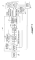
Fig. 3 is a more detailed schematic diagram of the control system ofFig. 2 ; and -
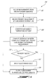
Fig. 4 is a flowchart of a method for control of the subchamber temperature of the engine, in accordance with an illustrative embodiment. - Referring to
Fig. 1 , a rotaryinternal combustion engine 10 known as a Wankel engine is schematically shown. In a particular embodiment, therotary engine 10 is used in a compound cycle engine system such as described in Lents et al.'sUS patent No. 7,753,036 issued July 13, 2010 , as described in Julien et al.'sUS patent No. 7,775,044 issued August 17, 2010 , or as described inU.S. published patent applications Nos. 2014/0020380 A1 and2014/0020381 A1 . The compound cycle engine system may be used as a prime mover engine, such as on an aircraft or other vehicle, or in any other suitable application. In any event, in such a system, air is compressed by a compressor before entering the Wankel engine, and the engine drives one or more turbine(s) of the compound engine. In another embodiment, therotary engine 10 is used with a turbocharger without being compounded; in another embodiment, therotary engine 10 is used without a turbocharger, with air at atmospheric pressure, as a stand-alone engine. In one embodiment, therotary engine 10 may be applicable to land base systems including, but not limited to, generators. - The
engine 10 comprises anouter body 12 having axially-spacedend walls 14 with aperipheral wall 18 extending therebetween to form arotor cavity 20. Theinner surface 19 of theperipheral wall 18 of thecavity 20 has a profile defining two lobes, which is preferably an epitrochoid. - An inner body or
rotor 24 is received within thecavity 20, with the geometrical axis of therotor 24 being offset from and parallel to the axis of theouter body 12. Therotor 24 has axially spaced end faces 26 adjacent to the outerbody end walls 14, and aperipheral face 28 extending therebetween. Theperipheral face 28 defines three circumferentially-spacedapex portions 30 and a generally triangular profile with outwardly arched sides. Theapex portions 30 are in sealing engagement with the inner surface ofperipheral wall 18 to form three rotatingworking chambers 32 between theinner rotor 24 andouter body 12. A recess (not shown) is defined in theperipheral face 28 of therotor 24 between each pair ofadjacent apex portions 30, to form part of thecorresponding chamber 32. - The
working chambers 32 are sealed. Eachrotor apex portion 30 has anapex seal 52 extending from oneend face 26 to the other and protruding radially from theperipheral face 28. Eachapex seal 52 is biased radially outwardly against theperipheral wall 18 through a respective spring. Anend seal 54 engages each end of eachapex seal 52, and is biased against therespective end wall 14 through a suitable spring. Eachend face 26 of therotor 24 has at least one arc-shaped face seal 60 running from eachapex portion 30 to eachadjacent apex portion 30, adjacent to but inwardly of the rotor periphery throughout its length. A spring urges eachface seal 60 axially outwardly so that theface seal 60 projects axially away from the adjacentrotor end face 26 into sealing engagement with theadjacent end wall 14 of the cavity. Eachface seal 60 is in sealing engagement with theend seal 54 adjacent each end thereof. - Although not shown, the
rotor 24 is journaled on an eccentric portion of a shaft and includes a phasing gear co-axial with the rotor axis, which is meshed with a fixed stator phasing gear secured to the outer body co-axially with the shaft. The shaft rotates therotor 24 and the meshed gears guide therotor 24 to perform orbital revolutions within the rotor cavity. The shaft rotates three times for each complete rotation of therotor 24 as it moves around therotor cavity 20. Oil seals are provided around the phasing gear to prevent leakage flow of lubricating oil radially outwardly thereof between the respectiverotor end face 26 and outerbody end wall 14. - At least one
inlet port 44 is defined through one of theend walls 14 or theperipheral wall 18 for admitting air (atmospheric or compressed) into one of theworking chambers 32, and at least oneexhaust port 46 is defined through one of theend walls 14 or theperipheral wall 18 for discharge of the exhaust gases from theworking chambers 32. The inlet andexhaust ports rotor 24, eachchamber 32 moves around thecavity 20 with a variable volume to undergo the four phases of intake, compression, expansion and exhaust, these phases being similar to the strokes in a reciprocating-type internal combustion engine having a four-stroke cycle. - In a particular embodiment, the inlet and
exhaust ports rotary engine 10 operates under the principle of the Miller or Atkinson cycle, with its volumetric compression ratio lower than its volumetric expansion ratio. In another embodiment, the inlet andexhaust ports - The
engine 10 includes apilot subchamber 72 defined in theouter body 12, for pilot fuel injection and ignition. In the embodiment shown, thepilot subchamber 72 is provided in aninsert 34 received in acorresponding hole 36 defined through theperipheral wall 18 of theouter body 12. Theinsert 34 is retained to theperipheral wall 18 using any adequate type of connection, including, but not limited to, fasteners, welding, brazing, retention through a cover overlapping theinsert 34 and connected to theperipheral wall 18, etc. In another embodiment, thepilot subchamber 72 is directly defined in theperipheral wall 18. - In the embodiment shown, the
insert body 34 has theentire pilot subchamber 72 defined therein, shown here with a circular cross-section. Other geometries are also possible, including but not limited to cylindrical, conical, frustoconical, wedge-shaped profiles, etc. Theinsert 34 includes at least one outlet opening 74 defined therein for communication with thecavity 20, and thesubchamber 72 has a shape forming a reduced cross-section adjacent the opening(s) 74, such that the opening(s) 74 define a restriction to the flow between thesubchamber 72 and thecavity 20. The opening(s) 74 may have various shapes and/or be defined by a pattern of multiple holes. - The
particular insert 34 shown is provided only as an example, and it is understood that other geometries and/or positions within theperipheral wall 18 are possible for theinsert 34. In a particular embodiment, theinsert 34 is made of a material having greater high temperature properties and/or lower thermal conductivity than that of theperipheral wall 18, which may be for example made of aluminum. In one embodiment, theinsert 34 is made of a nickel or cobalt based super alloy. Alternately, as mentioned above, theinsert 34 may be omitted and thepilot subchamber 72 be directly defined in theperipheral wall 18 if theperipheral wall 18 is made of a material having sufficient heat resistance and adequate high temperature properties to resist the high temperatures within thesubchamber 72. - The
peripheral wall 18 has a main injectorelongated hole 40 defined therethrough, in communication with therotor cavity 20 and spaced apart from thepilot subchamber 72. Amain fuel injector 42 is received and retained within thiscorresponding hole 40, with the tip of themain injector 42 communicating with thecavity 20 at a point spaced apart from thepilot subchamber 72. Themain injector 42 is located rearwardly of thepilot subchamber 72 with respect to the direction R of the rotor rotation and revolution, and is angled to direct fuel forwardly into each of therotating chambers 32 sequentially with a tip hole pattern designed for an adequate spray. - The
peripheral wall 18 also has a pilot injectorelongated hole 76 defined therethrough in communication with thesubchamber 72. Apilot fuel injector 78 is received and retained within thecorresponding hole 76, with the tip of thepilot injector 78 being in communication with thesubchamber 72, for example by terminating in a corresponding opening defined in theinsert 34 between thesubchamber 72 and thepilot injector hole 76. - The
pilot injector 78 andmain injector 42 inject fuel, which in a particular embodiment is heavy fuel e.g. diesel, kerosene (jet fuel), equivalent biofuel, etc. into thechambers 32. Alternately, the fuel may be any other adequate type of fuel suitable for injection as described, including non-heavy fuel such as for example gasoline or liquid hydrogen fuel. In a particular embodiment, at least 0.5% and up to 20% of the fuel is injected through thepilot injector 78, and the remainder is injected through themain injector 42. In another particular embodiment, at most 10% of the fuel is injected through thepilot injector 78. In another particular embodiment, at most 5% of the fuel is injected through thepilot injector 78. Themain injector 42 injects the fuel such that eachrotating chamber 32 when in the combustion phase contains a lean mixture of air and fuel. - The
peripheral wall 18 and, in the embodiment shown, insertbody 34 have an ignition element elongatedhole 82 defined therein in communication with thesubchamber 72. Anignition element 84 is received and retained within the correspondinghole 82 and positioned to ignite fuel within thesubchamber 72, e.g. with the tip of theignition element 84 being received in thesubchamber 72. In the embodiment shown, theignition element 84 is a glow plug. Other configurations are also possible, including for example having theignition element 84 completely received within theinsert 34, and/or ignition element(s) 84 of any other adequate type, including but not limited to plasma ignition, laser ignition, spark plug, microwave, other types of ignition elements, etc. - Referring now to
Fig. 2 , acontrol system 100 for the subchamber temperature of theengine 10 will now be described. Thesystem 100 may be used to control the ignition of theengine 10 and more particularly to maintain the temperature in thesubchamber 72 at a level sufficient to cause ignition. Still, it should be understood that thesystem 100 may be used for other applications. Thesystem 100 comprises acontrol unit 102, which is coupled to theengine 10 as well as toengine sensors 104, and asubchamber temperature sensor 106. Thecontrol unit 102 may comprise a digital computer or Engine Control Unit (ECU) (not shown) using a Central Processing Unit (CPU) (not shown). - In an embodiment where the
engine 10 is used in a compound engine in an aircraft where air is compressed by a compressor before entering theengine 10 and theengine 10 drives one or more turbine(s) of the compound engine, thesystem 100 may further includeaircraft sensors 108. Theaircraft sensors 108 may be used to measure operating parameters of the aircraft (not shown) theengine 10 is coupled to. Theaircraft sensors 108 may comprise a speed sensor, a pressure sensor, or any other suitable instrument known to those skilled in the art for providing information about the aircraft's flight situation. In one embodiment, theaircraft sensors 108 may provide a measurement of the aircraft's speed (e.g. Mach number). - The
engine sensors 104 may be used to measure the engine's operating parameters and illustratively comprise at least one of a pressure sensor and/or a temperature sensor for respectively measuring a pressure and/or a temperature near or at the engine's inlet port 44 (e.g., in a conduit providing fluid communication between the compressor and the inlet port 44). A speed sensor may also be used to measure a speed of rotation of therotor 24 of theengine 10. It should be understood that other sensors may apply. - The
subchamber temperature sensor 106 may be used to take a measurement indicative of a present temperature in thesubchamber 72 of theengine 10. For this purpose, thesubchamber temperature sensor 106 may be positioned in thepilot subchamber 72 or alternatively be coupled to the wall delimiting thesubchamber 72. In a particular embodiment where thetemperature sensor 106 is adapted to measure the gas temperature in thesubchamber 72, thetemperature sensor 106 may be an integral part a portion of the ignition element 84 (e.g. glow plug) received in thesubchamber 72. In a particular embodiment where thetemperature sensor 106 is adapted to measure the wall temperature of thesubchamber 72, thetemperature sensor 106 may be provided as a thermocouple coupled to the metal wall. As such, the subchamber temperature measurement acquired by thesensor 106 may be the gas temperature in thesubchamber 72 or the material temperature of the subchamber's wall. In another embodiment, the measurement acquired by thesensor 106 may be another measurement indicative of the subchamber temperature, including, but not limited to, a temperature of theinsert 34. - As will be described further below, upon receiving the measurements from the
sensors control unit 102 may determine therefrom the value of the subchamber temperature that should be achieved for optimal operation of theengine 10. Thecontrol unit 102 may then output to theengine 10 at least one control signal for causing the subchamber temperature to be adjusted towards the optimal value. For instance, the at least one control signal output by thecontrol unit 102 may be representative of a command for adjusting an intensity of theignition element 84. Alternatively, the control signal may be a request for thepilot injector 78 to inject with a certain timing a given quantity of fuel into thesubchamber 72. In this manner, the temperature of thesubchamber 72 can be accurately controlled. - Referring to
Fig. 3 , thecontrol unit 102 illustratively comprises a receivingmodule 202, asetpoint computation module 204, anoptional feedforward module 206, anerror computation module 208, and a subchambertemperature control module 210. The readings from theengine sensors 104, thesubchamber temperature sensor 106, and, if applicable, theaircraft sensors 108 may be received at the receivingmodule 202. The receivingmodule 202 may then send a signal comprising the received sensor readings to thesetpoint computation module 204. From the received signal, thesetpoint computation module 204 may compute a target value, i.e. the setpoint, of the subchamber temperature, which the subchambertemperature control module 208 should aim to reach. The value of the setpoint may be adjusted according to the operating parameters of theengine 10 and, if applicable, of the aircraft (not shown) as received from theengine sensors 104 and, if applicable, theaircraft sensors 108. For instance, it may be desirable to achieve a first subchamber temperature setpoint for a first set of pressure, temperature, and rotation speed readings of theengine 10 while it may be desirable to achieve a second subchamber temperature setpoint for a second set of pressure, temperature, and rotation speed readings. For example, the setpoint may be provided as a map or table with relation to one or more of pressure, temperature, and rotation speed readings. It should be understood that the subchambertemperature control module 208 may alternatively set the value of the setpoint to a predetermined value, e.g. 1000°F (538°C). - The setpoint value output by the
setpoint computation module 204 is then sent to theerror computation module 208, which may further receive from the receiving module 202 a subchamber temperature signal comprising a present measurement from thesubchamber temperature sensor 106. Theerror computation module 208 may then compute a difference between the computed setpoint and the present subchamber temperature measurement. The value of the difference is then sent to the subchambertemperature control module 210, which may generate on the basis thereof at least one control signal indicative of a request to adjust the subchamber temperature. In particular, the subchambertemperature control module 210 may determine from the difference received from theerror computation module 208 the adjustment required for adjusting the subchamber temperature towards the setpoint. - The subchamber
temperature control module 210 may then determine at least one engine component whose operation may be modified to achieve the desired adjustment. The subchambertemperature control module 210 may accordingly generate a control signal for commanding the engine component in question to perform the adjustment. In one embodiment, the subchambertemperature control module 210 may indeed generate at least one of an intensity control signal, an injector quantity control signal, and an injector timing control signal. The intensity control signal may be output to theignition element 84 for causing a desired adjustment, e.g. an increase or a decrease in a heating intensity of theignition element 84 when theignition element 84 is heatable (e.g. glow plug or other heating element), a change in timing and/or energizing time of the ignition element 84 (e.g. plasma ignition, laser ignition, spark plug). This may in turn vary, i.e. increase or decrease, the temperature in thesubchamber 72 towards the setpoint. The injector quantity control signal may further be output to thepilot injector 78 for causing the latter to adjust the quantity of fuel it injects into thesubchamber 72 in each injection pulse, thereby modifying the subchamber temperature accordingly. The injector timing control signal may also be output to thepilot injector 78 for controlling the timing of the fuel injection by thepilot injector 78 to further modify the subchamber temperature. For example, in a particular embodiment, the temperature in thesubchamber 72 may be increased by increasing the quantity of fuel injected by thepilot injector 78, timing the pilot injection so that it happens earlier in the combustion cycle, and/or increasing the temperature of aheatable ignition element 84. - In this manner, by altering the operation of the
ignition element 84 and/or thepilot injector 78, the temperature in thesubchamber 72 can be accurately controlled towards the desired setpoint value. Thesubchamber temperature sensor 106 may then acquire a new reading of the subchamber temperature and this reading may be fed back to thecontrol unit 102. Thecontrol unit 102 may then assess from the received data whether the desired temperature setpoint has been reached. If this is not the case, new control signal(s) may be generated for further adjustment. Precise closed-loop control of the subchamber temperature can then be achieved. - It should be understood that the subchamber
temperature control module 210 may determine which ones of the above-mentioned control signals to generate in accordance with the engine and aircraft operating parameter measurements received from theengine sensors 104 and, if applicable, theaircraft sensors 108. For instance, if theengine 10 is operating on a cold day, it may be desirable for the temperature of thesubchamber 72 to be adjusted by controlling the operation of theignition element 84 rather than that of thepilot injector 78. In this case, the subchambertemperature control module 210, upon receiving a measurement of the temperature at the engine's input from theengine sensors 104, may determine that only the intensity control signal is to be generated for output to theignition element 84. In other cases, the measurements received from theengine sensors 104 and theaircraft sensors 108 may indicate that it is desirable for the subchamber temperature to be controlled via thepilot injector 78 only or alternatively via both theignition element 84 and thepilot injector 78 for additional precision. The subchambertemperature control module 210 may therefore generate the corresponding control signals accordingly. It should also be understood that additional control signals may be generated to control the subchamber temperature. For instance, although not illustrated, it should be understood that thecontrol unit 102 may output control signal(s) to themain injector 42 so that the control parameters thereof may be altered to achieve the desired subchamber temperature. - In one embodiment, the receiving
module 202 may be also adapted to detect a transient mode of operation of theengine 10, for example on the basis of the measurements received from theengine sensors 104 and, if applicable, theaircraft sensors 108 and/or when a given control is actuated by a user (e.g. actuation of throttle in an aircraft). When such a mode is detected, the receivingmodule 202 may send the aircraft/engine sensor signal to thefeedforward module 206. The latter may then introduce additional compensation element to anticipate a response of theengine 10 operating in the transient mode. For instance, in the transient mode, a rapid throttle movement commanded by a pilot of the aircraft may result in additional power being requested by theengine 10. In this case, in order to control the temperature of thesubchamber 72, it may be desirable to anticipate the engine's response. For this purpose, thefeedforward module 206 may therefore predict the quantity and the timing of fuel that should be injected by thepilot injector 78 with theengine 10 in transient mode. Thefeedforward module 206 may then output to the subchamber temperature control module 210 a signal indicative of the predicted values. The subchambertemperature control module 210 may then take into account the predictions of thefeedforward module 206 in generating the control signal(s) for adjusting the temperature of thesubchamber 72, thereby achieving optimum control. In particular, the subchambertemperature control module 210 may generate the control signal(s) so as to ensure that, in the transient mode, the subchamber temperature remains as close as possible to the setpoint computed by thesetpoint computation module 204. - Referring now to
Fig. 4 , amethod 300 for closed-loop control of the subchamber temperature of theengine 10 will now be described. Themethod 300 comprises receiving atstep 302 operating parameter measurements from the aircraft/engine sensor(s), as discussed above with reference toFig. 2 . Themethod 300 further comprises receiving at step 304 a present measurement of the subchamber temperature from the subchamber temperature sensor. The subchamber temperature setpoint may then be computed atstep 306 on the basis of the received operating parameter measurements. A difference between the computed setpoint and the present subchamber temperature measurement may then be computed atstep 308. Optionally, thenext step 310 may then be to determine, e.g. from the operating parameter measurements, whether the engine is operating in transient mode. If this is the case, feedforward logic may be applied atstep 312 to anticipate the engine's response in the transient mode and predict the quantity and timing of fuel injections, as discussed herein above. At least one subchamber temperature control signal may then be output atstep 314. Such signal(s) may comprise an intensity control signal for controlling the intensity of the ignition element, an injector quantity control signal for controlling the quantity of fuel injected by the pilot injector, and an injector timing control signal for controlling the timing of the pilot injector's fuel injections. If it was determined atstep 310 that the engine is not in transient mode, or ifsteps method 300 may flow directly to thestep 314 of outputting the control signal(s). As discussed above, upon receiving the control signal(s), the ignition element and/or the pilot injector of the engine may modify their operation in order to reach the temperature setpoint computed atstep 306. - The teachings herein are applicable to many rotary engine types, and not just Wankel engines. In a particular embodiment, the rotary engine may be a single or eccentric type rotary engine in which the rotor rotates about a fixed center of rotation. For example, the rotary engine may be a sliding vane engine, such as described in
US patent No. 5,524,587 issued June 11, 1996 or inUS patent No. 5,522,356 issued June 4, 1996 . In another particular embodiment, the rotary engine may be an oscillatory rotating engine, including two or more rotors rotating at different angular velocities, causing the distance between portions of the rotors to vary and as such the chamber volume to change. In another particular embodiment, the rotary engine may be a planetary rotating engine having a different geometry than that of the Wankel engine, such as for example a planetary engine having a rotor cavity with an epitrochoid profile defining three lobes and a rotor with four apex portions. Examples of such non-Wankel rotary engines are shown in Applicant'sU.S. application No. 14/796,185 filed January 25, 2013 - The teachings herein are also applicable to other types of internal combustion engines having a pilot subchamber for ignition, such as for example reciprocating engines.
- The above description is meant to be exemplary only, and one skilled in the art will recognize that changes may be made to the embodiments described without departing from the scope of the invention disclosed. Modifications which fall within the scope of the present invention will be apparent to those skilled in the art, in light of a review of this disclosure, and such modifications are intended to fall within the appended claims.
Claims (15)
- A system for controlling a temperature in a pilot subchamber (72) for pilot injection of fuel in an internal combustion engine, the system comprising:a receiving unit (202) adapted to
receive at least one first measurement of at least one engine operating parameter, and
receive a second measurement indicative of a present temperature in the subchamber (72); anda processing unit adapted to
compute from the at least one first measurement a setpoint for the temperature in the subchamber,
generate in response to the second measurement at least one control signal indicative of a request to adjust the present temperature towards the setpoint, and
send the at least one control signal to the engine. - The system as defined in claim 1, wherein the internal combustion engine is a rotary engine is coupled to an aircraft, the receiving unit (202) being adapted to also receive at least one third measurement of at least one aircraft operating parameter, and the processing unit is adapted to compute from the at least one first measurement and the at least one third measurement the setpoint for the temperature in the subchamber.
- The system as defined in claim 2, wherein the receiving unit (202) is adapted to receive the at least one third measurement representative of a speed of the aircraft.
- The system as defined in claim 2 or 3, wherein the processing unit is adapted to generate the at least one control signal as an injector quantity control signal for modifying a quantity of fuel injected into the subchamber (72) by a pilot injector (78) of the engine and as an injector timing control signal for modifying a timing of a fuel injection by the pilot injector (78), and wherein the processing unit is further adapted to detect a transient mode of the engine from the at least one first measurement and the at least one third measurement, to predict the quantity of the fuel and the timing of the fuel injection required for adjusting the present temperature towards the setpoint, and to generate the at least one control signal accordingly.
- The system as defined in any preceding claim, wherein the processing unit is adapted to compute a difference between the setpoint and the present temperature and to generate the at least one control signal on the basis of the difference.
- The system as defined in any preceding claim, wherein the processing unit is adapted to generate the at least one control signal as at least one of an intensity control signal for modifying an intensity of an ignition element (84) coupled to the subchamber (72), an injector quantity control signal for modifying a quantity of fuel injected into the subchamber (72) by a pilot injector (78) of the engine, and an injector timing control signal for modifying a timing of a fuel injection by the pilot injector (78).
- The system as defined in any preceding claim, wherein the receiving unit (202) is adapted to receive the second measurement from one of a temperature sensor (106) positioned in the subchamber (72), the present temperature corresponding to a gas temperature in the subchamber (72), and a temperature sensor (106) coupled to a wall of the subchamber (72), the second measurement representative of the present temperature of the wall.
- The system as defined in any preceding claim, wherein the engine is a rotary engine, the receiving unit (202) being adapted to receive the at least one first measurement comprising at least one of a pressure at an inlet port (44) of the engine, a temperature at the inlet port (44) of the engine, and a speed of rotation of a rotor (24) of the engine.
- A method for controlling a temperature in a pilot subchamber (72) for pilot injection of fuel in an internal combustion engine, the method comprising:receiving (302) at least one first measurement of at least one engine operating parameter;receiving (304) a second measurement indicative of a present temperature in the subchamber (72);computing (306) from the at least one first measurement a setpoint for the temperature in the subchamber;generating (314) in response to the second measurement at least one control signal indicative of a request to adjust the present temperature towards the setpoint; andsending the at least one control signal to the engine.
- The method as defined in claim 9, wherein the internal combustion engine is a rotary engine is coupled to an aircraft, the method further comprising receiving at least one third measurement of at least one aircraft operating parameter, and the setpoint for the temperature in the subchamber (72) is computed from the at least one first measurement and the at least one third measurement.
- The method as defined in claim 10, wherein generating the at least one control signal comprises generating at least one of an injector quantity control signal for modifying a quantity of fuel injected into the subchamber by a pilot injector (78) of the engine and an injector timing control signal for modifying a timing of a fuel injection by the pilot injector (78), the method further comprising detecting (310) a transient mode of the engine from the at least one first measurement and the at least one third measurement, predicting the quantity of the fuel and the timing of the fuel injection required for adjusting the present temperature towards the setpoint, and generating the at least one control signal accordingly.
- The method as defined in claim 9, 10 or 11, further comprising computing (308) a difference between the setpoint and the present temperature and generating the at least one control signal on the basis of the difference.
- The method as defined in any one of claims 9 to 12, wherein generating (314) the at least one control signal comprises generating at least one of an intensity control signal for modifying an intensity of an ignition element (84) coupled to the subchamber (72), an injector quantity control signal for modifying a quantity of fuel injected into the subchamber (72) by a pilot injector (78) of the engine, and an injector timing control signal for modifying a timing of a fuel injection by the pilot injector (78).
- The method as defined in any one of claims 9 to 13, wherein receiving the second measurement comprises receiving the second measurement from one of a temperature sensor (106) positioned in the subchamber (72), the present temperature corresponding to a gas temperature in the subchamber (72), and a temperature sensor (106) coupled to a wall of the subchamber (72), the second measurement representative of the present temperature of the wall.
- A system for controlling a temperature in a pilot subchamber for pilot injection of fuel in an internal combustion engine, the system comprising:means (202) for receiving at least one first measurement of at least one engine operating parameter;means (202) for receiving a second measurement indicative of a present temperature in the subchamber;means (204) for computing from the at least one first measurement a setpoint for the temperature in the subchamber;means (210) for generating in response to the second measurement at least one control signal indicative of a request to adjust the present temperature towards the setpoint; andmeans for sending the at least one control signal to the engine.
Priority Applications (1)
| Application Number | Priority Date | Filing Date | Title |
|---|---|---|---|
| PL14158295T PL2775125T3 (en) | 2013-03-08 | 2014-03-07 | System for pilot subchamber temperature control |
Applications Claiming Priority (1)
| Application Number | Priority Date | Filing Date | Title |
|---|---|---|---|
| US13/789,989 US10280830B2 (en) | 2013-03-08 | 2013-03-08 | System for pilot subchamber temperature control |
Publications (3)
| Publication Number | Publication Date |
|---|---|
| EP2775125A2 true EP2775125A2 (en) | 2014-09-10 |
| EP2775125A3 EP2775125A3 (en) | 2015-08-12 |
| EP2775125B1 EP2775125B1 (en) | 2018-12-12 |
Family
ID=50272328
Family Applications (1)
| Application Number | Title | Priority Date | Filing Date |
|---|---|---|---|
| EP14158295.7A Active EP2775125B1 (en) | 2013-03-08 | 2014-03-07 | System for pilot subchamber temperature control |
Country Status (5)
| Country | Link |
|---|---|
| US (2) | US10280830B2 (en) |
| EP (1) | EP2775125B1 (en) |
| CA (1) | CA2845166C (en) |
| ES (1) | ES2714529T3 (en) |
| PL (1) | PL2775125T3 (en) |
Cited By (4)
| Publication number | Priority date | Publication date | Assignee | Title |
|---|---|---|---|---|
| EP3299607A1 (en) * | 2016-09-23 | 2018-03-28 | Pratt & Whitney Canada Corp. | Method of operating an engine having a pilot subchamber at partial load conditions |
| US10584639B2 (en) | 2014-08-18 | 2020-03-10 | Woodward, Inc. | Torch igniter |
| US11421601B2 (en) | 2019-03-28 | 2022-08-23 | Woodward, Inc. | Second stage combustion for igniter |
| US12305578B2 (en) | 2020-06-23 | 2025-05-20 | Woodward, Inc. | Ignition system for power generation engine |
Families Citing this family (12)
| Publication number | Priority date | Publication date | Assignee | Title |
|---|---|---|---|---|
| US9528434B1 (en) | 2011-07-28 | 2016-12-27 | Pratt & Whitney Canada Corp. | Rotary internal combustion engine with pilot subchamber |
| US10557407B2 (en) | 2011-07-28 | 2020-02-11 | Pratt & Whitney Canada Corp. | Rotary internal combustion engine with pilot subchamber |
| US9038594B2 (en) | 2011-07-28 | 2015-05-26 | Pratt & Whitney Canada Corp. | Rotary internal combustion engine with pilot subchamber |
| US10544732B2 (en) | 2011-07-28 | 2020-01-28 | Pratt & Whitney Canada Corp. | Rotary internal combustion engine with removable subchamber insert |
| US10280830B2 (en) * | 2013-03-08 | 2019-05-07 | Pratt & Whitney Canada Corp. | System for pilot subchamber temperature control |
| US9200563B2 (en) | 2013-03-12 | 2015-12-01 | Pratt & Whitney Canada Corp. | Internal combustion engine with common rail pilot and main injection |
| US9399947B2 (en) | 2013-03-12 | 2016-07-26 | Pratt & Whitney Canada Corp. | Internal combustion engine with pilot and main injection |
| US10041402B2 (en) | 2016-05-12 | 2018-08-07 | Pratt & Whitney Canada Corp. | Internal combustion engine with split pilot injection |
| US10145291B1 (en) | 2017-10-10 | 2018-12-04 | Pratt & Whitney Canada Corp. | Rotary engine and method of combusting fuel |
| US10801394B2 (en) | 2017-11-29 | 2020-10-13 | Pratt & Whitney Canada Corp. | Rotary engine with pilot subchambers |
| US11408329B2 (en) * | 2019-12-19 | 2022-08-09 | Board Of Trustees Of Michigan State University | Engine turbulent jet ignition system |
| US11795879B2 (en) | 2021-12-20 | 2023-10-24 | General Electric Company | Combustor with an igniter provided within at least one of a fuel injector or a compressed air passage |
Citations (6)
| Publication number | Priority date | Publication date | Assignee | Title |
|---|---|---|---|---|
| US5522356A (en) | 1992-09-04 | 1996-06-04 | Spread Spectrum | Method and apparatus for transferring heat energy from engine housing to expansion fluid employed in continuous combustion, pinned vane type, integrated rotary compressor-expander engine system |
| US5524587A (en) | 1995-03-03 | 1996-06-11 | Mallen Research Ltd. Partnership | Sliding vane engine |
| US7753036B2 (en) | 2007-07-02 | 2010-07-13 | United Technologies Corporation | Compound cycle rotary engine |
| US7775044B2 (en) | 2003-02-24 | 2010-08-17 | Pratt & Whitney Canada Corp. | Low volumetric compression ratio integrated turbo-compound rotary engine |
| US20140020380A1 (en) | 2012-07-20 | 2014-01-23 | Jean Thomassin | Compound cycle engine |
| US20140020381A1 (en) | 2012-07-20 | 2014-01-23 | Sébastien BOLDUC | Compound cycle engine |
Family Cites Families (26)
| Publication number | Priority date | Publication date | Assignee | Title |
|---|---|---|---|---|
| US780023A (en) | 1901-04-20 | 1905-01-17 | James Clegg | Illuminated sign. |
| US3861361A (en) * | 1973-11-29 | 1975-01-21 | Gen Motors Corp | Rotary engine with piston scavenged precombustion chambers |
| US4089305A (en) * | 1975-04-03 | 1978-05-16 | Gregg Oscar P | Rotary internal combustion engine |
| US4259932A (en) | 1976-05-26 | 1981-04-07 | Ford Motor Company | Internal combustion engine control system |
| DE3108087A1 (en) * | 1981-03-04 | 1982-09-23 | Ingo 8831 Zell Gierstorfer | Four-stroke rotary engine |
| US4518268A (en) | 1983-03-18 | 1985-05-21 | Sun Electric Corporation | Diesel engine diagnostic system |
| US6951211B2 (en) * | 1996-07-17 | 2005-10-04 | Bryant Clyde C | Cold air super-charged internal combustion engine, working cycle and method |
| US5836282A (en) | 1996-12-27 | 1998-11-17 | Samsung Electronics Co., Ltd. | Method of reducing pollution emissions in a two-stroke sliding vane internal combustion engine |
| US6125813A (en) * | 1997-06-09 | 2000-10-03 | Patrick Power Products, Inc. | Prechamber combustion for a rotary diesel engine |
| US6162034A (en) | 1999-03-01 | 2000-12-19 | Mallen Research Ltd., Partnership | Vane pumping machine utilizing invar-class alloys for maximizing operating performance and reducing pollution emissions |
| US6244240B1 (en) | 1999-04-30 | 2001-06-12 | Mallen Research Limited Partnership | Rotary positive-displacement scavenging device for rotary vane pumping machine |
| US6321713B1 (en) | 2000-08-02 | 2001-11-27 | Mallen Research Corporation | Hot wall combustion insert for a rotary vane pumping machine |
| SE519954C2 (en) * | 2000-08-09 | 2003-04-29 | Elster Messtechnik Gmbh | Apparatus and method for senseless contact of a rotor state of rotation |
| WO2002095202A1 (en) * | 2001-05-23 | 2002-11-28 | Moe Cordell R | Rotary engine |
| JP2005240712A (en) | 2004-02-27 | 2005-09-08 | Mitsubishi Heavy Ind Ltd | Gas engine |
| DE102004023409B4 (en) * | 2004-05-12 | 2007-05-16 | Gottfried Schubert | High-compression gasoline engine with throttle control, spark ignition and direct fuel injection into a pre-combustion chamber |
| RS50751B (en) | 2004-10-21 | 2010-08-31 | Anglo Operations Limited | PROCESSING METHODS IN THE PRESENCE OF HYDROCHLORIC ACID TO OBTAIN USEFUL METAL FROM ORE |
| US7756036B2 (en) | 2005-12-22 | 2010-07-13 | Intuitive Surgical Operations, Inc. | Synchronous data communication |
| US9010293B2 (en) | 2006-04-07 | 2015-04-21 | David A. Blank | Combustion control via homogeneous combustion radical ignition (HCRI) or partial HCRI in cyclic IC engines |
| WO2008043154A1 (en) | 2006-10-13 | 2008-04-17 | Bernhard Philberth | A combustion engine with fuel conditioning |
| EP2009268B1 (en) | 2007-06-27 | 2009-10-14 | Honda Motor Co., Ltd | Control system for internal combustion engine |
| JP4861915B2 (en) | 2007-06-27 | 2012-01-25 | 本田技研工業株式会社 | Control device for internal combustion engine |
| US9528434B1 (en) | 2011-07-28 | 2016-12-27 | Pratt & Whitney Canada Corp. | Rotary internal combustion engine with pilot subchamber |
| US9664047B2 (en) | 2012-08-23 | 2017-05-30 | Mallen Research Limited Partnership | Positive displacement rotary devices with uniquely configured voids |
| US10280830B2 (en) * | 2013-03-08 | 2019-05-07 | Pratt & Whitney Canada Corp. | System for pilot subchamber temperature control |
| CA2941920C (en) * | 2014-04-02 | 2021-07-27 | Roberto FANARA | Hcci rotary engine with variable compression ratio control |
-
2013
- 2013-03-08 US US13/789,989 patent/US10280830B2/en active Active
-
2014
- 2014-03-06 CA CA2845166A patent/CA2845166C/en active Active
- 2014-03-07 ES ES14158295T patent/ES2714529T3/en active Active
- 2014-03-07 PL PL14158295T patent/PL2775125T3/en unknown
- 2014-03-07 EP EP14158295.7A patent/EP2775125B1/en active Active
-
2019
- 2019-03-19 US US16/357,840 patent/US10865699B2/en active Active
Patent Citations (6)
| Publication number | Priority date | Publication date | Assignee | Title |
|---|---|---|---|---|
| US5522356A (en) | 1992-09-04 | 1996-06-04 | Spread Spectrum | Method and apparatus for transferring heat energy from engine housing to expansion fluid employed in continuous combustion, pinned vane type, integrated rotary compressor-expander engine system |
| US5524587A (en) | 1995-03-03 | 1996-06-11 | Mallen Research Ltd. Partnership | Sliding vane engine |
| US7775044B2 (en) | 2003-02-24 | 2010-08-17 | Pratt & Whitney Canada Corp. | Low volumetric compression ratio integrated turbo-compound rotary engine |
| US7753036B2 (en) | 2007-07-02 | 2010-07-13 | United Technologies Corporation | Compound cycle rotary engine |
| US20140020380A1 (en) | 2012-07-20 | 2014-01-23 | Jean Thomassin | Compound cycle engine |
| US20140020381A1 (en) | 2012-07-20 | 2014-01-23 | Sébastien BOLDUC | Compound cycle engine |
Cited By (7)
| Publication number | Priority date | Publication date | Assignee | Title |
|---|---|---|---|---|
| US10584639B2 (en) | 2014-08-18 | 2020-03-10 | Woodward, Inc. | Torch igniter |
| EP3299607A1 (en) * | 2016-09-23 | 2018-03-28 | Pratt & Whitney Canada Corp. | Method of operating an engine having a pilot subchamber at partial load conditions |
| US10072559B2 (en) | 2016-09-23 | 2018-09-11 | Pratt & Whitney Canada Corp. | Method of operating an engine having a pilot subchamber at partial load conditions |
| US10533486B2 (en) | 2016-09-23 | 2020-01-14 | Pratt & Whitney Canada Corp. | Method of operating an engine having a pilot subchamber at partial load conditions |
| US11421601B2 (en) | 2019-03-28 | 2022-08-23 | Woodward, Inc. | Second stage combustion for igniter |
| US11965466B2 (en) | 2019-03-28 | 2024-04-23 | Woodward, Inc. | Second stage combustion for igniter |
| US12305578B2 (en) | 2020-06-23 | 2025-05-20 | Woodward, Inc. | Ignition system for power generation engine |
Also Published As
| Publication number | Publication date |
|---|---|
| EP2775125B1 (en) | 2018-12-12 |
| US20190211741A1 (en) | 2019-07-11 |
| PL2775125T3 (en) | 2019-05-31 |
| ES2714529T3 (en) | 2019-05-28 |
| US20140251258A1 (en) | 2014-09-11 |
| CA2845166A1 (en) | 2014-09-08 |
| EP2775125A3 (en) | 2015-08-12 |
| US10865699B2 (en) | 2020-12-15 |
| US10280830B2 (en) | 2019-05-07 |
| CA2845166C (en) | 2022-09-27 |
Similar Documents
| Publication | Publication Date | Title |
|---|---|---|
| US10865699B2 (en) | System for pilot subchamber temperature control | |
| US10267217B2 (en) | Internal combustion engine with common rail injection | |
| EP2778367B1 (en) | Internal combustion engine with pilot and main injection | |
| US10458325B2 (en) | Rotary internal combustion engine with pilot subchamber and ignition element | |
| CA2844015C (en) | Rotary internal combustion engine with pilot subchamber | |
| US9528434B1 (en) | Rotary internal combustion engine with pilot subchamber | |
| CA2782749C (en) | Rotary internal combustion engine with pilot subchamber | |
| EP3351763B1 (en) | Method of operating a rotary engine | |
| EP4474627A1 (en) | Rotary engine with single dual-fuel injector | |
| EP4474632A1 (en) | Rotary engine with dual-fuel injectors |
Legal Events
| Date | Code | Title | Description |
|---|---|---|---|
| PUAI | Public reference made under article 153(3) epc to a published international application that has entered the european phase |
Free format text: ORIGINAL CODE: 0009012 |
|
| 17P | Request for examination filed |
Effective date: 20140307 |
|
| AK | Designated contracting states |
Kind code of ref document: A2 Designated state(s): AL AT BE BG CH CY CZ DE DK EE ES FI FR GB GR HR HU IE IS IT LI LT LU LV MC MK MT NL NO PL PT RO RS SE SI SK SM TR |
|
| AX | Request for extension of the european patent |
Extension state: BA ME |
|
| PUAL | Search report despatched |
Free format text: ORIGINAL CODE: 0009013 |
|
| AK | Designated contracting states |
Kind code of ref document: A3 Designated state(s): AL AT BE BG CH CY CZ DE DK EE ES FI FR GB GR HR HU IE IS IT LI LT LU LV MC MK MT NL NO PL PT RO RS SE SI SK SM TR |
|
| AX | Request for extension of the european patent |
Extension state: BA ME |
|
| RIC1 | Information provided on ipc code assigned before grant |
Ipc: F02D 35/02 20060101AFI20150707BHEP Ipc: F02D 41/40 20060101ALN20150707BHEP Ipc: F02B 19/10 20060101ALI20150707BHEP Ipc: F02D 41/30 20060101ALN20150707BHEP Ipc: F02B 53/10 20060101ALI20150707BHEP |
|
| R17P | Request for examination filed (corrected) |
Effective date: 20160212 |
|
| RBV | Designated contracting states (corrected) |
Designated state(s): AL AT BE BG CH CY CZ DE DK EE ES FI FR GB GR HR HU IE IS IT LI LT LU LV MC MK MT NL NO PL PT RO RS SE SI SK SM TR |
|
| GRAP | Despatch of communication of intention to grant a patent |
Free format text: ORIGINAL CODE: EPIDOSNIGR1 |
|
| STAA | Information on the status of an ep patent application or granted ep patent |
Free format text: STATUS: GRANT OF PATENT IS INTENDED |
|
| RIC1 | Information provided on ipc code assigned before grant |
Ipc: F02B 19/10 20060101ALI20180601BHEP Ipc: F02B 53/10 20060101ALI20180601BHEP Ipc: F02D 35/02 20060101AFI20180601BHEP Ipc: F02D 41/40 20060101ALN20180601BHEP Ipc: F02D 41/30 20060101ALN20180601BHEP |
|
| INTG | Intention to grant announced |
Effective date: 20180621 |
|
| GRAS | Grant fee paid |
Free format text: ORIGINAL CODE: EPIDOSNIGR3 |
|
| GRAA | (expected) grant |
Free format text: ORIGINAL CODE: 0009210 |
|
| STAA | Information on the status of an ep patent application or granted ep patent |
Free format text: STATUS: THE PATENT HAS BEEN GRANTED |
|
| AK | Designated contracting states |
Kind code of ref document: B1 Designated state(s): AL AT BE BG CH CY CZ DE DK EE ES FI FR GB GR HR HU IE IS IT LI LT LU LV MC MK MT NL NO PL PT RO RS SE SI SK SM TR |
|
| REG | Reference to a national code |
Ref country code: GB Ref legal event code: FG4D |
|
| REG | Reference to a national code |
Ref country code: CH Ref legal event code: EP |
|
| REG | Reference to a national code |
Ref country code: AT Ref legal event code: REF Ref document number: 1076317 Country of ref document: AT Kind code of ref document: T Effective date: 20181215 |
|
| REG | Reference to a national code |
Ref country code: DE Ref legal event code: R096 Ref document number: 602014037716 Country of ref document: DE |
|
| REG | Reference to a national code |
Ref country code: IE Ref legal event code: FG4D |
|
| REG | Reference to a national code |
Ref country code: CH Ref legal event code: NV Representative=s name: VALIPAT S.A. GEVERS SA, CH |
|
| REG | Reference to a national code |
Ref country code: CH Ref legal event code: PCAR Free format text: NEW ADDRESS: RUE DES NOYERS 11, 2000 NEUCHATEL (CH) |
|
| REG | Reference to a national code |
Ref country code: NL Ref legal event code: MP Effective date: 20181212 |
|
| REG | Reference to a national code |
Ref country code: LT Ref legal event code: MG4D |
|
| PG25 | Lapsed in a contracting state [announced via postgrant information from national office to epo] |
Ref country code: FI Free format text: LAPSE BECAUSE OF FAILURE TO SUBMIT A TRANSLATION OF THE DESCRIPTION OR TO PAY THE FEE WITHIN THE PRESCRIBED TIME-LIMIT Effective date: 20181212 Ref country code: LT Free format text: LAPSE BECAUSE OF FAILURE TO SUBMIT A TRANSLATION OF THE DESCRIPTION OR TO PAY THE FEE WITHIN THE PRESCRIBED TIME-LIMIT Effective date: 20181212 Ref country code: BG Free format text: LAPSE BECAUSE OF FAILURE TO SUBMIT A TRANSLATION OF THE DESCRIPTION OR TO PAY THE FEE WITHIN THE PRESCRIBED TIME-LIMIT Effective date: 20190312 Ref country code: HR Free format text: LAPSE BECAUSE OF FAILURE TO SUBMIT A TRANSLATION OF THE DESCRIPTION OR TO PAY THE FEE WITHIN THE PRESCRIBED TIME-LIMIT Effective date: 20181212 Ref country code: LV Free format text: LAPSE BECAUSE OF FAILURE TO SUBMIT A TRANSLATION OF THE DESCRIPTION OR TO PAY THE FEE WITHIN THE PRESCRIBED TIME-LIMIT Effective date: 20181212 Ref country code: NO Free format text: LAPSE BECAUSE OF FAILURE TO SUBMIT A TRANSLATION OF THE DESCRIPTION OR TO PAY THE FEE WITHIN THE PRESCRIBED TIME-LIMIT Effective date: 20190312 |
|
| REG | Reference to a national code |
Ref country code: ES Ref legal event code: FG2A Ref document number: 2714529 Country of ref document: ES Kind code of ref document: T3 Effective date: 20190528 |
|
| PG25 | Lapsed in a contracting state [announced via postgrant information from national office to epo] |
Ref country code: AL Free format text: LAPSE BECAUSE OF FAILURE TO SUBMIT A TRANSLATION OF THE DESCRIPTION OR TO PAY THE FEE WITHIN THE PRESCRIBED TIME-LIMIT Effective date: 20181212 Ref country code: GR Free format text: LAPSE BECAUSE OF FAILURE TO SUBMIT A TRANSLATION OF THE DESCRIPTION OR TO PAY THE FEE WITHIN THE PRESCRIBED TIME-LIMIT Effective date: 20190313 Ref country code: RS Free format text: LAPSE BECAUSE OF FAILURE TO SUBMIT A TRANSLATION OF THE DESCRIPTION OR TO PAY THE FEE WITHIN THE PRESCRIBED TIME-LIMIT Effective date: 20181212 Ref country code: SE Free format text: LAPSE BECAUSE OF FAILURE TO SUBMIT A TRANSLATION OF THE DESCRIPTION OR TO PAY THE FEE WITHIN THE PRESCRIBED TIME-LIMIT Effective date: 20181212 |
|
| PG25 | Lapsed in a contracting state [announced via postgrant information from national office to epo] |
Ref country code: NL Free format text: LAPSE BECAUSE OF FAILURE TO SUBMIT A TRANSLATION OF THE DESCRIPTION OR TO PAY THE FEE WITHIN THE PRESCRIBED TIME-LIMIT Effective date: 20181212 |
|
| PG25 | Lapsed in a contracting state [announced via postgrant information from national office to epo] |
Ref country code: PT Free format text: LAPSE BECAUSE OF FAILURE TO SUBMIT A TRANSLATION OF THE DESCRIPTION OR TO PAY THE FEE WITHIN THE PRESCRIBED TIME-LIMIT Effective date: 20190412 |
|
| PG25 | Lapsed in a contracting state [announced via postgrant information from national office to epo] |
Ref country code: SK Free format text: LAPSE BECAUSE OF FAILURE TO SUBMIT A TRANSLATION OF THE DESCRIPTION OR TO PAY THE FEE WITHIN THE PRESCRIBED TIME-LIMIT Effective date: 20181212 Ref country code: RO Free format text: LAPSE BECAUSE OF FAILURE TO SUBMIT A TRANSLATION OF THE DESCRIPTION OR TO PAY THE FEE WITHIN THE PRESCRIBED TIME-LIMIT Effective date: 20181212 Ref country code: IS Free format text: LAPSE BECAUSE OF FAILURE TO SUBMIT A TRANSLATION OF THE DESCRIPTION OR TO PAY THE FEE WITHIN THE PRESCRIBED TIME-LIMIT Effective date: 20190412 Ref country code: SM Free format text: LAPSE BECAUSE OF FAILURE TO SUBMIT A TRANSLATION OF THE DESCRIPTION OR TO PAY THE FEE WITHIN THE PRESCRIBED TIME-LIMIT Effective date: 20181212 Ref country code: EE Free format text: LAPSE BECAUSE OF FAILURE TO SUBMIT A TRANSLATION OF THE DESCRIPTION OR TO PAY THE FEE WITHIN THE PRESCRIBED TIME-LIMIT Effective date: 20181212 |
|
| REG | Reference to a national code |
Ref country code: DE Ref legal event code: R097 Ref document number: 602014037716 Country of ref document: DE |
|
| PLBE | No opposition filed within time limit |
Free format text: ORIGINAL CODE: 0009261 |
|
| STAA | Information on the status of an ep patent application or granted ep patent |
Free format text: STATUS: NO OPPOSITION FILED WITHIN TIME LIMIT |
|
| PG25 | Lapsed in a contracting state [announced via postgrant information from national office to epo] |
Ref country code: DK Free format text: LAPSE BECAUSE OF FAILURE TO SUBMIT A TRANSLATION OF THE DESCRIPTION OR TO PAY THE FEE WITHIN THE PRESCRIBED TIME-LIMIT Effective date: 20181212 Ref country code: SI Free format text: LAPSE BECAUSE OF FAILURE TO SUBMIT A TRANSLATION OF THE DESCRIPTION OR TO PAY THE FEE WITHIN THE PRESCRIBED TIME-LIMIT Effective date: 20181212 Ref country code: MC Free format text: LAPSE BECAUSE OF FAILURE TO SUBMIT A TRANSLATION OF THE DESCRIPTION OR TO PAY THE FEE WITHIN THE PRESCRIBED TIME-LIMIT Effective date: 20181212 |
|
| 26N | No opposition filed |
Effective date: 20190913 |
|
| PG25 | Lapsed in a contracting state [announced via postgrant information from national office to epo] |
Ref country code: LU Free format text: LAPSE BECAUSE OF NON-PAYMENT OF DUE FEES Effective date: 20190307 |
|
| REG | Reference to a national code |
Ref country code: BE Ref legal event code: MM Effective date: 20190331 |
|
| PG25 | Lapsed in a contracting state [announced via postgrant information from national office to epo] |
Ref country code: IE Free format text: LAPSE BECAUSE OF NON-PAYMENT OF DUE FEES Effective date: 20190307 |
|
| PG25 | Lapsed in a contracting state [announced via postgrant information from national office to epo] |
Ref country code: BE Free format text: LAPSE BECAUSE OF NON-PAYMENT OF DUE FEES Effective date: 20190331 |
|
| PG25 | Lapsed in a contracting state [announced via postgrant information from national office to epo] |
Ref country code: TR Free format text: LAPSE BECAUSE OF FAILURE TO SUBMIT A TRANSLATION OF THE DESCRIPTION OR TO PAY THE FEE WITHIN THE PRESCRIBED TIME-LIMIT Effective date: 20181212 |
|
| PG25 | Lapsed in a contracting state [announced via postgrant information from national office to epo] |
Ref country code: MT Free format text: LAPSE BECAUSE OF NON-PAYMENT OF DUE FEES Effective date: 20190307 |
|
| REG | Reference to a national code |
Ref country code: AT Ref legal event code: UEP Ref document number: 1076317 Country of ref document: AT Kind code of ref document: T Effective date: 20181212 |
|
| PG25 | Lapsed in a contracting state [announced via postgrant information from national office to epo] |
Ref country code: CY Free format text: LAPSE BECAUSE OF FAILURE TO SUBMIT A TRANSLATION OF THE DESCRIPTION OR TO PAY THE FEE WITHIN THE PRESCRIBED TIME-LIMIT Effective date: 20181212 |
|
| PG25 | Lapsed in a contracting state [announced via postgrant information from national office to epo] |
Ref country code: HU Free format text: LAPSE BECAUSE OF FAILURE TO SUBMIT A TRANSLATION OF THE DESCRIPTION OR TO PAY THE FEE WITHIN THE PRESCRIBED TIME-LIMIT; INVALID AB INITIO Effective date: 20140307 |
|
| PG25 | Lapsed in a contracting state [announced via postgrant information from national office to epo] |
Ref country code: MK Free format text: LAPSE BECAUSE OF FAILURE TO SUBMIT A TRANSLATION OF THE DESCRIPTION OR TO PAY THE FEE WITHIN THE PRESCRIBED TIME-LIMIT Effective date: 20181212 |
|
| P01 | Opt-out of the competence of the unified patent court (upc) registered |
Effective date: 20230531 |
|
| PGFP | Annual fee paid to national office [announced via postgrant information from national office to epo] |
Ref country code: ES Payment date: 20250401 Year of fee payment: 12 |
|
| PGFP | Annual fee paid to national office [announced via postgrant information from national office to epo] |
Ref country code: CH Payment date: 20250401 Year of fee payment: 12 |
|
| REG | Reference to a national code |
Ref country code: CH Ref legal event code: U11 Free format text: ST27 STATUS EVENT CODE: U-0-0-U10-U11 (AS PROVIDED BY THE NATIONAL OFFICE) Effective date: 20260401 |
|
| PGFP | Annual fee paid to national office [announced via postgrant information from national office to epo] |
Ref country code: GB Payment date: 20260220 Year of fee payment: 13 |
|
| PGFP | Annual fee paid to national office [announced via postgrant information from national office to epo] |
Ref country code: DE Payment date: 20260219 Year of fee payment: 13 |
|
| PGFP | Annual fee paid to national office [announced via postgrant information from national office to epo] |
Ref country code: AT Payment date: 20260223 Year of fee payment: 13 |
|
| PGFP | Annual fee paid to national office [announced via postgrant information from national office to epo] |
Ref country code: IT Payment date: 20260219 Year of fee payment: 13 |
|
| PGFP | Annual fee paid to national office [announced via postgrant information from national office to epo] |
Ref country code: FR Payment date: 20260219 Year of fee payment: 13 |
|
| PGFP | Annual fee paid to national office [announced via postgrant information from national office to epo] |
Ref country code: CZ Payment date: 20260227 Year of fee payment: 13 |
|
| PGFP | Annual fee paid to national office [announced via postgrant information from national office to epo] |
Ref country code: PL Payment date: 20260220 Year of fee payment: 13 |