EP2775103A2 - CMC turbine engine component - Google Patents
CMC turbine engine component Download PDFInfo
- Publication number
- EP2775103A2 EP2775103A2 EP14157416.0A EP14157416A EP2775103A2 EP 2775103 A2 EP2775103 A2 EP 2775103A2 EP 14157416 A EP14157416 A EP 14157416A EP 2775103 A2 EP2775103 A2 EP 2775103A2
- Authority
- EP
- European Patent Office
- Prior art keywords
- component
- cmc
- seal
- ceramic
- rotor
- Prior art date
- Legal status (The legal status is an assumption and is not a legal conclusion. Google has not performed a legal analysis and makes no representation as to the accuracy of the status listed.)
- Granted
Links
- 239000011153 ceramic matrix composite Substances 0.000 claims abstract description 34
- 239000000919 ceramic Substances 0.000 claims abstract description 26
- 238000007789 sealing Methods 0.000 claims abstract description 26
- 239000000835 fiber Substances 0.000 claims abstract description 14
- 239000002184 metal Substances 0.000 claims abstract description 13
- 229910052751 metal Inorganic materials 0.000 claims abstract description 13
- 239000011159 matrix material Substances 0.000 claims abstract description 6
- 239000002131 composite material Substances 0.000 claims abstract description 3
- 239000011226 reinforced ceramic Substances 0.000 claims abstract description 3
- 239000000203 mixture Substances 0.000 claims description 3
- 239000007789 gas Substances 0.000 description 12
- 239000000945 filler Substances 0.000 description 10
- 238000005266 casting Methods 0.000 description 4
- 238000001816 cooling Methods 0.000 description 4
- 238000011065 in-situ storage Methods 0.000 description 4
- 239000000463 material Substances 0.000 description 4
- 238000002485 combustion reaction Methods 0.000 description 3
- 230000001141 propulsive effect Effects 0.000 description 3
- PXHVJJICTQNCMI-UHFFFAOYSA-N Nickel Chemical compound [Ni] PXHVJJICTQNCMI-UHFFFAOYSA-N 0.000 description 2
- 230000006835 compression Effects 0.000 description 2
- 238000007906 compression Methods 0.000 description 2
- 239000000446 fuel Substances 0.000 description 2
- 230000003014 reinforcing effect Effects 0.000 description 2
- 238000005507 spraying Methods 0.000 description 2
- 230000003746 surface roughness Effects 0.000 description 2
- 229920002134 Carboxymethyl cellulose Polymers 0.000 description 1
- 230000006978 adaptation Effects 0.000 description 1
- 239000000853 adhesive Substances 0.000 description 1
- 230000001070 adhesive effect Effects 0.000 description 1
- 235000010948 carboxy methyl cellulose Nutrition 0.000 description 1
- 229920006184 cellulose methylcellulose Polymers 0.000 description 1
- 238000012710 chemistry, manufacturing and control Methods 0.000 description 1
- 238000003754 machining Methods 0.000 description 1
- 230000004048 modification Effects 0.000 description 1
- 238000012986 modification Methods 0.000 description 1
- 229910052759 nickel Inorganic materials 0.000 description 1
- 239000000126 substance Substances 0.000 description 1
- 239000002759 woven fabric Substances 0.000 description 1
Images


Classifications
-
- F—MECHANICAL ENGINEERING; LIGHTING; HEATING; WEAPONS; BLASTING
- F01—MACHINES OR ENGINES IN GENERAL; ENGINE PLANTS IN GENERAL; STEAM ENGINES
- F01D—NON-POSITIVE DISPLACEMENT MACHINES OR ENGINES, e.g. STEAM TURBINES
- F01D11/00—Preventing or minimising internal leakage of working-fluid, e.g. between stages
- F01D11/08—Preventing or minimising internal leakage of working-fluid, e.g. between stages for sealing space between rotor blade tips and stator
- F01D11/12—Preventing or minimising internal leakage of working-fluid, e.g. between stages for sealing space between rotor blade tips and stator using a rubstrip, e.g. erodible. deformable or resiliently-biased part
-
- F—MECHANICAL ENGINEERING; LIGHTING; HEATING; WEAPONS; BLASTING
- F01—MACHINES OR ENGINES IN GENERAL; ENGINE PLANTS IN GENERAL; STEAM ENGINES
- F01D—NON-POSITIVE DISPLACEMENT MACHINES OR ENGINES, e.g. STEAM TURBINES
- F01D11/00—Preventing or minimising internal leakage of working-fluid, e.g. between stages
- F01D11/005—Sealing means between non relatively rotating elements
-
- F—MECHANICAL ENGINEERING; LIGHTING; HEATING; WEAPONS; BLASTING
- F01—MACHINES OR ENGINES IN GENERAL; ENGINE PLANTS IN GENERAL; STEAM ENGINES
- F01D—NON-POSITIVE DISPLACEMENT MACHINES OR ENGINES, e.g. STEAM TURBINES
- F01D11/00—Preventing or minimising internal leakage of working-fluid, e.g. between stages
- F01D11/08—Preventing or minimising internal leakage of working-fluid, e.g. between stages for sealing space between rotor blade tips and stator
-
- F—MECHANICAL ENGINEERING; LIGHTING; HEATING; WEAPONS; BLASTING
- F01—MACHINES OR ENGINES IN GENERAL; ENGINE PLANTS IN GENERAL; STEAM ENGINES
- F01D—NON-POSITIVE DISPLACEMENT MACHINES OR ENGINES, e.g. STEAM TURBINES
- F01D5/00—Blades; Blade-carrying members; Heating, heat-insulating, cooling or antivibration means on the blades or the members
- F01D5/12—Blades
- F01D5/28—Selecting particular materials; Particular measures relating thereto; Measures against erosion or corrosion
- F01D5/282—Selecting composite materials, e.g. blades with reinforcing filaments
-
- F—MECHANICAL ENGINEERING; LIGHTING; HEATING; WEAPONS; BLASTING
- F01—MACHINES OR ENGINES IN GENERAL; ENGINE PLANTS IN GENERAL; STEAM ENGINES
- F01D—NON-POSITIVE DISPLACEMENT MACHINES OR ENGINES, e.g. STEAM TURBINES
- F01D5/00—Blades; Blade-carrying members; Heating, heat-insulating, cooling or antivibration means on the blades or the members
- F01D5/12—Blades
- F01D5/28—Selecting particular materials; Particular measures relating thereto; Measures against erosion or corrosion
- F01D5/284—Selection of ceramic materials
-
- F—MECHANICAL ENGINEERING; LIGHTING; HEATING; WEAPONS; BLASTING
- F01—MACHINES OR ENGINES IN GENERAL; ENGINE PLANTS IN GENERAL; STEAM ENGINES
- F01D—NON-POSITIVE DISPLACEMENT MACHINES OR ENGINES, e.g. STEAM TURBINES
- F01D9/00—Stators
- F01D9/02—Nozzles; Nozzle boxes; Stator blades; Guide conduits, e.g. individual nozzles
- F01D9/04—Nozzles; Nozzle boxes; Stator blades; Guide conduits, e.g. individual nozzles forming ring or sector
- F01D9/041—Nozzles; Nozzle boxes; Stator blades; Guide conduits, e.g. individual nozzles forming ring or sector using blades
-
- F—MECHANICAL ENGINEERING; LIGHTING; HEATING; WEAPONS; BLASTING
- F05—INDEXING SCHEMES RELATING TO ENGINES OR PUMPS IN VARIOUS SUBCLASSES OF CLASSES F01-F04
- F05D—INDEXING SCHEME FOR ASPECTS RELATING TO NON-POSITIVE-DISPLACEMENT MACHINES OR ENGINES, GAS-TURBINES OR JET-PROPULSION PLANTS
- F05D2230/00—Manufacture
-
- F—MECHANICAL ENGINEERING; LIGHTING; HEATING; WEAPONS; BLASTING
- F05—INDEXING SCHEMES RELATING TO ENGINES OR PUMPS IN VARIOUS SUBCLASSES OF CLASSES F01-F04
- F05D—INDEXING SCHEME FOR ASPECTS RELATING TO NON-POSITIVE-DISPLACEMENT MACHINES OR ENGINES, GAS-TURBINES OR JET-PROPULSION PLANTS
- F05D2240/00—Components
- F05D2240/10—Stators
- F05D2240/11—Shroud seal segments
-
- F—MECHANICAL ENGINEERING; LIGHTING; HEATING; WEAPONS; BLASTING
- F05—INDEXING SCHEMES RELATING TO ENGINES OR PUMPS IN VARIOUS SUBCLASSES OF CLASSES F01-F04
- F05D—INDEXING SCHEME FOR ASPECTS RELATING TO NON-POSITIVE-DISPLACEMENT MACHINES OR ENGINES, GAS-TURBINES OR JET-PROPULSION PLANTS
- F05D2240/00—Components
- F05D2240/80—Platforms for stationary or moving blades
-
- F—MECHANICAL ENGINEERING; LIGHTING; HEATING; WEAPONS; BLASTING
- F05—INDEXING SCHEMES RELATING TO ENGINES OR PUMPS IN VARIOUS SUBCLASSES OF CLASSES F01-F04
- F05D—INDEXING SCHEME FOR ASPECTS RELATING TO NON-POSITIVE-DISPLACEMENT MACHINES OR ENGINES, GAS-TURBINES OR JET-PROPULSION PLANTS
- F05D2250/00—Geometry
- F05D2250/60—Structure; Surface texture
- F05D2250/62—Structure; Surface texture smooth or fine
-
- F—MECHANICAL ENGINEERING; LIGHTING; HEATING; WEAPONS; BLASTING
- F05—INDEXING SCHEMES RELATING TO ENGINES OR PUMPS IN VARIOUS SUBCLASSES OF CLASSES F01-F04
- F05D—INDEXING SCHEME FOR ASPECTS RELATING TO NON-POSITIVE-DISPLACEMENT MACHINES OR ENGINES, GAS-TURBINES OR JET-PROPULSION PLANTS
- F05D2300/00—Materials; Properties thereof
- F05D2300/60—Properties or characteristics given to material by treatment or manufacturing
- F05D2300/603—Composites; e.g. fibre-reinforced
- F05D2300/6033—Ceramic matrix composites [CMC]
Definitions
- the present invention relates to a component of a gas turbine engine, the component being formed from a continuous fibre reinforced ceramic matrix composite (CMC).
- CMC ceramic matrix composite
- EP 0751104 discloses a ceramic segment having an abradable seal which is suitable for use with nickel base turbine blades
- EP 1965030 discloses a hollow section ceramic seal segment.
- the CMC can be continuous fibre reinforced.
- FIG. 1 shows schematically a longitudinal cross-section though a seal segment 1 which, in use, is positioned radially adjacent shroudless aerofoil blades 2 of the rotor of the engine.
- a circumferential row of such seal segments forms a shroud ring for the rotor.
- Neighbouring segments can be sealed to each other by strip seals, which are metal strips located in slots formed in side faces of neighbouring segments.
- Dash-dotted line 3 in Figure 1 indicates the line taken by such a strip seal from the front to the rear of the segment.
- the segments can be sealed to the outer casing 4 of the rotor via bird mouth seals 5 at front and rear races of the segments. Cooling air for the ring enters a space 6 formed between the segments and the casing.
- the strip and bird mouth seals are suitable for use with metallic seal segments.
- such seals require the segments to have high tolerance surface finishes of the type that can be achieved with metallic components.
- a problem associated with continuous fibre reinforced CMCs is that they generally have a surface texture similar to a woven fabric, which is not a suitable sealing face. The CMC surface can be ground to a high tolerance, but porosity in the CMC can then reduce sealing efficiency.
- the present invention provides a component of a gas turbine engine, the component being formed from a continuous fibre reinforced CMC; wherein the component has a sealing portion which, in use, makes sealing contact with an adjacent component of the engine, the sealing portion comprising a recess formed in the CMC and filled with a finer grade ceramic relative to the surrounding CMC, a metal or an intermetallic wherein the sealing contact between the component and the adjacent component can be effected by a flexible sealing member which conforms to the surface of the sealing portion.
- the filler (whether a finer grade ceramic, metal or intermetallic) can provide the component with a reduced surface roughness and reduced porosity. Further, by providing the filler in the recess it can be embedded in the CMC, whereby the filler, which may be less damage tolerant than the CMC, can be protected on multiple sides by the CMC.
- the present invention provides a gas turbine engine fitted with the component of the first aspect.
- the recess is filled with the finer grade ceramic.
- This may be a monolithic ceramic.
- the finer grade ceramic is also CMC, e.g. a short-fibre or particulate reinforced CMC.
- the finer grade ceramic may have substantially the same composition as the ceramic matrix of the CMC. In this way the chemical and mechanical compatibility can be improved. For example, the thermal expansion coefficients of the finer grade ceramic and the ceramic matrix of the CMC can be matched.
- a metal or intermetallic filler may be adopted.
- Such a filler may provide a more compatible surface for contact with the flexible seal than a ceramic filler can provide.
- the metal or intermetallic would generally need to be relatively thin to prevent excessive stresses and strains in the surrounding CMC. Also the metal or intermetallic should be able to withstand the operating temperature at the sealing portion.
- the flexible sealing member can be an alternative to a strip seal or a bird mouth seal.
- the sealing member can be a convolute seal such as a C-seal, a W-seal, an omega-seal or a bellow seal,
- the component can be a seal segment for a shroud ring of a rotor of the engine, the seal segment being positioned, in use, radially adjacent the rotor.
- the adjacent component may be a casing of rotor.
- the recess can be a channel formed in a face of the segment, such as a back face distal from the rotor.
- the channel may extend around the periphery of the face.
- the component can be a nozzle guide vane.
- a vane may have an aerofoil body which extends between inner and outer endwall platforms, the recess being formed in one of the platforms. Indeed, a filled recess may be formed in each platform.
- the adjacent component may be a neighbouring endwall component (i.e. to front or rear of the platform, or it may be the platform of a next nozzle guide vane in a row of guide vanes).
- a ducted fan gas turbine engine incorporating the invention is generally indicated at 10 and has a principal and rotational axis X-X.
- the engine comprises, in axial flow series, an air intake 11, a propulsive fan 12, an intermediate pressure compressor 13, a high-pressure compressor 14, combustion equipment 15, a high-pressure turbine 16, an intermediate pressure turbine 17, a low-pressure turbine 18 and a core engine exhaust nozzle 19.
- a nacelle 21 generally surrounds the engine 10 and defines the intake 11, a bypass duct 22 and a bypass exhaust nozzle 23.
- air entering the intake 11 is accelerated by the fan 12 to produce two air flows: a first air flow A into the intermediate pressure compressor 13 and a second air flow B which passes through the bypass duct 22 to provide propulsive thrust.
- the intermediate pressure compressor 13 compresses the air flow A directed into it before delivering that air to the high pressure compressor 14 where further compression takes place.
- the compressed air exhausted from the high-pressure compressor 14 is directed into the combustion equipment 15 where it is mixed with fuel and the mixture combusted.
- the resultant hot combustion products then expand through, and thereby drive the high, intermediate and low-pressure turbines 16, 17, 18 before being exhausted through the nozzle 19 to provide additional propulsive thrust.
- the high, intermediate and low-pressure turbines respectively drive the high and intermediate pressure compressors 14, 13 and the fan 12 by suitable interconnecting shafts.
- the high pressure turbine 16 includes an annular array of radially extending, shroudless rotor aerofoil blades.
- a shroud ring is positioned radially outwardly of the aerofoil blades.
- the shroud ring serves to define the radially outer extent of a short length of the gas passage through the high pressure turbine 16.
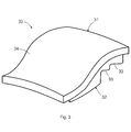
- FIG. 3 shows schematically an isometric view of one of the segments 30.
- the segment has a continuous fibre reinforced CMC main body 31 based on laid plys of reinforcing fibre.
- the gas-washed surface of the segment may be formed by a separate ceramic layer 32 bonded to the main body and shaped (e.g. machined) to provide needed gas-washed surface features, such as steps 33 to match sealing fins projecting from the blade tips. Cooling air for the ring enters spaces formed between the segments and a casing for the rotor.
- a flexible convolute seal such as a C-seal, W-seal, omega-seal or bellow seal
- the seal conforms to the segment back surface, taking on the general shape of the back face.
- a finer grade ceramic is embedded in the back face to provide a sealing portion of the segment.
- a channel 35 of CMC material is removed from the back face 34 around the periphery of the main body 31 of the segment 30, e.g. by machining.
- a finer grade (less coarse) filler ceramic 36 compatible with the parent CMC, is then embedded in the channel, e.g. by casting in situ, spraying in situ, or pre-casting and bonding in place with an adhesive, and is machined to provide a smooth, clean and low porosity outer surface on which to seal.
- the filler ceramic 36 which is less robust than the continuous fibre reinforced CMC, is protected on three sides by the channel, only the outer surface being exposed.
- FIG 6 shows schematically the segment on section A indicated on Figure 5 .
- a W-seal 37 seals between the smooth outer surface of the filler ceramic 36 and a typically metal component 38, which may be the rotor casing itself or an intermediate component. This seal helps to prevent high pressure cooling air (indicated by arrow B) in the space between the segment and the casing from escaping around the edges of the segment 30.
- the continuous fibre reinforced CMC component having a recessed sealing portion formed of finer grade ceramic may be another component of a gas turbine engine, such as nozzle guide vane, and in particular an endwall of such a vane.
- the channel may be filled with a metal or an intermetallic rather than finer grade ceramic.
- a metal or intermetallic would tend to provide a more compatible surface for contact with the flexible seal, and can also be embedded by casting in situ, spraying in situ, or pre-casting and bonding.
- the metal or intermetallic would generally need to be relatively thin to prevent excessive stresses and strains in the surrounding CMC.
- the metal or intermetallic should be able to withstand the operating temperature at the seal location. Accordingly, the exemplary embodiments of the invention set forth above are considered to be illustrative and not limiting. Various changes to the described embodiments may be made without departing from the spirit and scope of the invention.
Abstract
Description
- The present invention relates to a component of a gas turbine engine, the component being formed from a continuous fibre reinforced ceramic matrix composite (CMC).
- The performance of gas turbine engines, whether measured in terms of efficiency or specific output, is improved by increasing the turbine gas temperature. It is therefore desirable to operate the turbines at the highest possible temperatures. For any engine cycle compression ratio or bypass ratio, increasing the turbine entry gas temperature produces more specific thrust (e.g. engine thrust per unit of air mass flow). However, as turbine entry temperatures increase, it is necessary to develop components and materials better able to withstand the increased temperatures.
- This has led to the replacement of metallic components, such as shroud segments, with CMC components having higher temperature capabilities. To accommodate the change in material, however, adaptations to the components have been proposed. For example,
EP 0751104 discloses a ceramic segment having an abradable seal which is suitable for use with nickel base turbine blades, andEP 1965030 discloses a hollow section ceramic seal segment. For improved strength and toughness, the CMC can be continuous fibre reinforced. - Gas turbine engine components often require sealing, e.g. to retain a back face air pressure, maintain cooling flows and protect specific fuel consumption (SFC). For example,
Figure 1 shows schematically a longitudinal cross-section though aseal segment 1 which, in use, is positioned radially adjacentshroudless aerofoil blades 2 of the rotor of the engine. A circumferential row of such seal segments forms a shroud ring for the rotor. Neighbouring segments can be sealed to each other by strip seals, which are metal strips located in slots formed in side faces of neighbouring segments. Dash-dottedline 3 inFigure 1 indicates the line taken by such a strip seal from the front to the rear of the segment. The segments can be sealed to the outer casing 4 of the rotor viabird mouth seals 5 at front and rear races of the segments. Cooling air for the ring enters a space 6 formed between the segments and the casing. - The strip and bird mouth seals are suitable for use with metallic seal segments. In particular, such seals require the segments to have high tolerance surface finishes of the type that can be achieved with metallic components. However, a problem associated with continuous fibre reinforced CMCs is that they generally have a surface texture similar to a woven fabric, which is not a suitable sealing face. The CMC surface can be ground to a high tolerance, but porosity in the CMC can then reduce sealing efficiency.
- It would be desirable to provide a continuous fibre reinforced CMC component having improved sealing capability.
- Accordingly, in a first aspect the present invention provides a component of a gas turbine engine, the component being formed from a continuous fibre reinforced CMC;
wherein the component has a sealing portion which, in use, makes sealing contact with an adjacent component of the engine, the sealing portion comprising a recess formed in the CMC and filled with a finer grade ceramic relative to the surrounding CMC, a metal or an intermetallic wherein the sealing contact between the component and the adjacent component can be effected by a flexible sealing member which conforms to the surface of the sealing portion. - Advantageously, the filler (whether a finer grade ceramic, metal or intermetallic) can provide the component with a reduced surface roughness and reduced porosity. Further, by providing the filler in the recess it can be embedded in the CMC, whereby the filler, which may be less damage tolerant than the CMC, can be protected on multiple sides by the CMC.
- In a second aspect the present invention provides a gas turbine engine fitted with the component of the first aspect.
- Optional features of the invention will now be set out. These are applicable singly or in any combination with any aspect of the invention.
- Preferably the recess is filled with the finer grade ceramic. This may be a monolithic ceramic. Another option, however, is for the finer grade ceramic to be another CMC, e.g. a short-fibre or particulate reinforced CMC.
- The finer grade ceramic may have substantially the same composition as the ceramic matrix of the CMC. In this way the chemical and mechanical compatibility can be improved. For example, the thermal expansion coefficients of the finer grade ceramic and the ceramic matrix of the CMC can be matched.
- On the other hand, a metal or intermetallic filler may be adopted. Such a filler may provide a more compatible surface for contact with the flexible seal than a ceramic filler can provide. However, the metal or intermetallic would generally need to be relatively thin to prevent excessive stresses and strains in the surrounding CMC. Also the metal or intermetallic should be able to withstand the operating temperature at the sealing portion.
- The flexible sealing member can be an alternative to a strip seal or a bird mouth seal. For example, the sealing member can be a convolute seal such as a C-seal, a W-seal, an omega-seal or a bellow seal,
- The component can be a seal segment for a shroud ring of a rotor of the engine, the seal segment being positioned, in use, radially adjacent the rotor. The adjacent component may be a casing of rotor. The recess can be a channel formed in a face of the segment, such as a back face distal from the rotor. For example, the channel may extend around the periphery of the face.
- Alternatively, the component can be a nozzle guide vane. Such a vane may have an aerofoil body which extends between inner and outer endwall platforms, the recess being formed in one of the platforms. Indeed, a filled recess may be formed in each platform. The adjacent component may be a neighbouring endwall component (i.e. to front or rear of the platform, or it may be the platform of a next nozzle guide vane in a row of guide vanes).
- Embodiments of the invention will now be described by way of example with reference to the accompanying drawings in which:
-
Figure 1 shows schematically a longitudinal cross-section through a seal segment for a shroud ring of a rotor of the engine; -
Figure 2 shows schematically a longitudinal cross-section through a gas turbine engine; -
Figure 3 shows schematically an isometric view of a seal segment; -
Figure 4 repeats the isometric view ofFigure 3 and indicates the position of a channel of CMC material removed from the back face of the segment; -
Figure 5 repeats the isometric view ofFigures 3 and4 and shows the channel filled with a finer grade filler ceramic; and -
Figure 6 shows schematically the seal segment on section A indicated onFigure 5 . - With reference to
Figure 2 , a ducted fan gas turbine engine incorporating the invention is generally indicated at 10 and has a principal and rotational axis X-X. The engine comprises, in axial flow series, an air intake 11, apropulsive fan 12, anintermediate pressure compressor 13, a high-pressure compressor 14,combustion equipment 15, a high-pressure turbine 16, anintermediate pressure turbine 17, a low-pressure turbine 18 and a coreengine exhaust nozzle 19. Anacelle 21 generally surrounds theengine 10 and defines the intake 11, abypass duct 22 and abypass exhaust nozzle 23. - During operation, air entering the intake 11 is accelerated by the
fan 12 to produce two air flows: a first air flow A into theintermediate pressure compressor 13 and a second air flow B which passes through thebypass duct 22 to provide propulsive thrust. Theintermediate pressure compressor 13 compresses the air flow A directed into it before delivering that air to thehigh pressure compressor 14 where further compression takes place. - The compressed air exhausted from the high-
pressure compressor 14 is directed into thecombustion equipment 15 where it is mixed with fuel and the mixture combusted. The resultant hot combustion products then expand through, and thereby drive the high, intermediate and low-pressure turbines nozzle 19 to provide additional propulsive thrust. The high, intermediate and low-pressure turbines respectively drive the high andintermediate pressure compressors fan 12 by suitable interconnecting shafts. - The
high pressure turbine 16 includes an annular array of radially extending, shroudless rotor aerofoil blades. A shroud ring is positioned radially outwardly of the aerofoil blades. The shroud ring serves to define the radially outer extent of a short length of the gas passage through thehigh pressure turbine 16. - The turbine gases flowing over the radially inward facing surface of the shroud ring are at extremely high temperatures. Consequently, the shroud ring is formed from an annular row of continuous fibre reinforced CMC seal segments, which are capable of withstanding those temperatures whilst maintaining their structural integrity.
Figure 3 shows schematically an isometric view of one of thesegments 30. The segment has a continuous fibre reinforced CMCmain body 31 based on laid plys of reinforcing fibre. The gas-washed surface of the segment, however, may be formed by a separateceramic layer 32 bonded to the main body and shaped (e.g. machined) to provide needed gas-washed surface features, such assteps 33 to match sealing fins projecting from the blade tips. Cooling air for the ring enters spaces formed between the segments and a casing for the rotor. - Instead of or in addition to sealing the edges of the segment (e.g. with strip seals and/or bird mouth seals), a flexible convolute seal (such as a C-seal, W-seal, omega-seal or bellow seal) is used on the
back face 34 of the segment near to the edges. The seal conforms to the segment back surface, taking on the general shape of the back face. However, because the seal would not conform well to the surface roughness created by the plies of reinforcing fibre, and because a machined CMC surface would have surface porosity that would reduce the effectiveness of a seal, a finer grade ceramic is embedded in the back face to provide a sealing portion of the segment. - More particularly, and as shown in
Figure 4 , achannel 35 of CMC material is removed from theback face 34 around the periphery of themain body 31 of thesegment 30, e.g. by machining. As shown inFigure 5 , a finer grade (less coarse)filler ceramic 36, compatible with the parent CMC, is then embedded in the channel, e.g. by casting in situ, spraying in situ, or pre-casting and bonding in place with an adhesive, and is machined to provide a smooth, clean and low porosity outer surface on which to seal. Advantageously, thefiller ceramic 36, which is less robust than the continuous fibre reinforced CMC, is protected on three sides by the channel, only the outer surface being exposed. -
Figure 6 shows schematically the segment on section A indicated onFigure 5 . A W-seal 37 seals between the smooth outer surface of thefiller ceramic 36 and a typicallymetal component 38, which may be the rotor casing itself or an intermediate component. This seal helps to prevent high pressure cooling air (indicated by arrow B) in the space between the segment and the casing from escaping around the edges of thesegment 30. - While the invention has been described in conjunction with the exemplary embodiments described above, many equivalent modifications and variations will be apparent to those skilled in the art when given this disclosure. For example, the continuous fibre reinforced CMC component having a recessed sealing portion formed of finer grade ceramic may be another component of a gas turbine engine, such as nozzle guide vane, and in particular an endwall of such a vane. In another example, the channel may be filled with a metal or an intermetallic rather than finer grade ceramic. A metal or intermetallic would tend to provide a more compatible surface for contact with the flexible seal, and can also be embedded by casting in situ, spraying in situ, or pre-casting and bonding. However, the metal or intermetallic would generally need to be relatively thin to prevent excessive stresses and strains in the surrounding CMC. Also the metal or intermetallic should be able to withstand the operating temperature at the seal location. Accordingly, the exemplary embodiments of the invention set forth above are considered to be illustrative and not limiting. Various changes to the described embodiments may be made without departing from the spirit and scope of the invention.
Claims (11)
- A component of a gas turbine engine, the component being formed from a continuous fibre reinforced ceramic matrix composite (CMC);
wherein the component has a sealing portion which, in use, makes sealing contact with an adjacent component of the engine, the sealing portion comprising a recess (35) formed in the CMC and filled with a finer grade ceramic (36) relative to the surrounding CMC, a metal or an intermetallic wherein sealing contact between the component and the adjacent component is effected by a flexible sealing member (37) which conforms to the surface of the sealing portion.. - A component according to claim 1, wherein the finer grade ceramic is a monolithic ceramic.
- A component according to claim 1 or 2, wherein the finer grade ceramic has substantially the same composition as the ceramic matrix of the CMC.
- A component according to any one of the previous claims which is a seal segment (30) for a shroud ring of a rotor of the engine, the seal segment being positioned, in use, radially adjacent the rotor.
- A seal segment according to claim 4, wherein the recess is a channel formed in a face of the segment.
- A seal segment according to claim 5, wherein the channel extends around the periphery of the face.
- A seal segment according to claim 5 or 6, wherein the face is a back face (34) distal from the rotor.
- A seal segment according to any one of claims 4 to 7, wherein the adjacent component is a casing (38) of rotor.
- A component according to any one of claims 1 to 3 which is a nozzle guide vane.
- A nozzle guide vane according to claim 9, wherein the vane has an aerofoil body which extends between inner and outer endwall platforms, the recess being formed in one of the platforms.
- A gas turbine engine fitted with the component of any one of the previous claims.
Applications Claiming Priority (1)
| Application Number | Priority Date | Filing Date | Title |
|---|---|---|---|
| GBGB1303995.3A GB201303995D0 (en) | 2013-03-06 | 2013-03-06 | CMC turbine engine component |
Publications (3)
| Publication Number | Publication Date |
|---|---|
| EP2775103A2 true EP2775103A2 (en) | 2014-09-10 |
| EP2775103A3 EP2775103A3 (en) | 2018-02-28 |
| EP2775103B1 EP2775103B1 (en) | 2019-05-08 |
Family
ID=48142500
Family Applications (1)
| Application Number | Title | Priority Date | Filing Date |
|---|---|---|---|
| EP14157416.0A Active EP2775103B1 (en) | 2013-03-06 | 2014-03-03 | CMC turbine engine component |
Country Status (3)
| Country | Link |
|---|---|
| US (1) | US9476316B2 (en) |
| EP (1) | EP2775103B1 (en) |
| GB (1) | GB201303995D0 (en) |
Cited By (7)
| Publication number | Priority date | Publication date | Assignee | Title |
|---|---|---|---|---|
| EP3051071A1 (en) * | 2015-01-29 | 2016-08-03 | Rolls-Royce Corporation | Turbine shroud and corresponding assembly method |
| EP3112600A1 (en) * | 2015-06-29 | 2017-01-04 | Rolls-Royce Corporation | Turbine shroud segment with flange-facing perimeter seal |
| EP3115561A1 (en) * | 2015-06-29 | 2017-01-11 | Rolls-Royce North American Technologies, Inc. | Turbine shroud segment with side perimeter seal |
| EP3214276A1 (en) * | 2016-02-26 | 2017-09-06 | General Electric Company | Thermal break in turbine nozzle and turbine shroud |
| US10577977B2 (en) | 2017-02-22 | 2020-03-03 | Rolls-Royce Corporation | Turbine shroud with biased retaining ring |
| US10876422B2 (en) | 2015-06-29 | 2020-12-29 | Rolls-Royce North American Technologies Inc. | Turbine shroud segment with buffer air seal system |
| US10934879B2 (en) | 2015-06-29 | 2021-03-02 | Rolls-Royce North American Technologies Inc. | Turbine shroud segment with load distribution springs |
Families Citing this family (19)
| Publication number | Priority date | Publication date | Assignee | Title |
|---|---|---|---|---|
| US9726043B2 (en) | 2011-12-15 | 2017-08-08 | General Electric Company | Mounting apparatus for low-ductility turbine shroud |
| CA2912428C (en) | 2013-05-17 | 2018-03-13 | General Electric Company | Cmc shroud support system of a gas turbine |
| JP6529013B2 (en) | 2013-12-12 | 2019-06-12 | ゼネラル・エレクトリック・カンパニイ | CMC shroud support system |
| US9719420B2 (en) * | 2014-06-02 | 2017-08-01 | General Electric Company | Gas turbine component and process for producing gas turbine component |
| CN106460542B (en) | 2014-06-12 | 2018-11-02 | 通用电气公司 | Shield hanger component |
| CA2951425C (en) | 2014-06-12 | 2019-12-24 | General Electric Company | Shroud hanger assembly |
| WO2015191174A1 (en) | 2014-06-12 | 2015-12-17 | General Electric Company | Multi-piece shroud hanger assembly |
| US9874104B2 (en) | 2015-02-27 | 2018-01-23 | General Electric Company | Method and system for a ceramic matrix composite shroud hanger assembly |
| US10472976B2 (en) * | 2015-06-05 | 2019-11-12 | Rolls-Royce Corporation | Machinable CMC insert |
| US10458653B2 (en) * | 2015-06-05 | 2019-10-29 | Rolls-Royce Corporation | Machinable CMC insert |
| US10465534B2 (en) | 2015-06-05 | 2019-11-05 | Rolls-Royce North American Technologies, Inc. | Machinable CMC insert |
| US20170030211A1 (en) * | 2015-07-28 | 2017-02-02 | General Electric Company | Seals with a conformable coating for turbomachinery |
| US10458268B2 (en) * | 2016-04-13 | 2019-10-29 | Rolls-Royce North American Technologies Inc. | Turbine shroud with sealed box segments |
| US10746037B2 (en) | 2016-11-30 | 2020-08-18 | Rolls-Royce Corporation | Turbine shroud assembly with tandem seals |
| US20180223681A1 (en) * | 2017-02-09 | 2018-08-09 | General Electric Company | Turbine engine shroud with near wall cooling |
| US10480337B2 (en) | 2017-04-18 | 2019-11-19 | Rolls-Royce North American Technologies Inc. | Turbine shroud assembly with multi-piece seals |
| US10663167B2 (en) | 2017-06-16 | 2020-05-26 | General Electric Company | Combustor assembly with CMC combustor dome |
| US10774665B2 (en) | 2018-07-31 | 2020-09-15 | General Electric Company | Vertically oriented seal system for gas turbine vanes |
| FR3124182B1 (en) * | 2021-06-21 | 2024-03-08 | Safran Aircraft Engines | Turbine ring sector made of particle-reinforced CMC material |
Family Cites Families (9)
| Publication number | Priority date | Publication date | Assignee | Title |
|---|---|---|---|---|
| GB9513252D0 (en) | 1995-06-29 | 1995-09-06 | Rolls Royce Plc | An abradable composition |
| US6893214B2 (en) * | 2002-12-20 | 2005-05-17 | General Electric Company | Shroud segment and assembly with surface recessed seal bridging adjacent members |
| FR2884564B1 (en) | 2005-04-15 | 2011-01-14 | Snecma Moteurs | METHOD OF ASSEMBLING TWO PARTS OF WHICH AT LEAST ONE IS OF COMPOSITE MATERIAL, INSERT FOR THE REALIZATION OF THE ASSEMBLY |
| GB0703827D0 (en) | 2007-02-28 | 2007-04-11 | Rolls Royce Plc | Rotor seal segment |
| FR2913717A1 (en) | 2007-03-15 | 2008-09-19 | Snecma Propulsion Solide Sa | Ring assembly for e.g. aircraft engine gas turbine, has centering unit constituted of metallic ring gear and bracket, and centering complete ring, where elastically deformable tab blocks rotation of ring around axis of ring |
| FR2939430B1 (en) * | 2008-12-04 | 2011-01-07 | Snecma Propulsion Solide | METHOD FOR SMOOTHING THE SURFACE OF A PIECE OF CMC MATERIAL |
| US20110219775A1 (en) * | 2010-03-12 | 2011-09-15 | Jarmon David C | High tolerance controlled surface for ceramic matrix composite component |
| US8998573B2 (en) * | 2010-10-29 | 2015-04-07 | General Electric Company | Resilient mounting apparatus for low-ductility turbine shroud |
| US8985944B2 (en) * | 2011-03-30 | 2015-03-24 | General Electric Company | Continuous ring composite turbine shroud |
-
2013
- 2013-03-06 GB GBGB1303995.3A patent/GB201303995D0/en not_active Ceased
-
2014
- 2014-03-03 EP EP14157416.0A patent/EP2775103B1/en active Active
- 2014-03-04 US US14/196,746 patent/US9476316B2/en active Active
Cited By (14)
| Publication number | Priority date | Publication date | Assignee | Title |
|---|---|---|---|---|
| US10100660B2 (en) | 2015-01-29 | 2018-10-16 | Rolls-Royce Corporation | Seals for gas turbine engines |
| EP3051071A1 (en) * | 2015-01-29 | 2016-08-03 | Rolls-Royce Corporation | Turbine shroud and corresponding assembly method |
| US10934879B2 (en) | 2015-06-29 | 2021-03-02 | Rolls-Royce North American Technologies Inc. | Turbine shroud segment with load distribution springs |
| EP3112600A1 (en) * | 2015-06-29 | 2017-01-04 | Rolls-Royce Corporation | Turbine shroud segment with flange-facing perimeter seal |
| EP3115561A1 (en) * | 2015-06-29 | 2017-01-11 | Rolls-Royce North American Technologies, Inc. | Turbine shroud segment with side perimeter seal |
| US11280206B2 (en) | 2015-06-29 | 2022-03-22 | Rolls-Royce North American Technologies Inc. | Turbine shroud segment with flange-facing perimeter seal |
| US10047624B2 (en) | 2015-06-29 | 2018-08-14 | Rolls-Royce North American Technologies Inc. | Turbine shroud segment with flange-facing perimeter seal |
| US10385718B2 (en) | 2015-06-29 | 2019-08-20 | Rolls-Royce North American Technologies, Inc. | Turbine shroud segment with side perimeter seal |
| US10577960B2 (en) | 2015-06-29 | 2020-03-03 | Rolls-Royce North American Technologies Inc. | Turbine shroud segment with flange-facing perimeter seal |
| US11125100B2 (en) | 2015-06-29 | 2021-09-21 | Rolls-Royce North American Technologies Inc. | Turbine shroud segment with side perimeter seal |
| US10876422B2 (en) | 2015-06-29 | 2020-12-29 | Rolls-Royce North American Technologies Inc. | Turbine shroud segment with buffer air seal system |
| US10208614B2 (en) | 2016-02-26 | 2019-02-19 | General Electric Company | Apparatus, turbine nozzle and turbine shroud |
| EP3214276A1 (en) * | 2016-02-26 | 2017-09-06 | General Electric Company | Thermal break in turbine nozzle and turbine shroud |
| US10577977B2 (en) | 2017-02-22 | 2020-03-03 | Rolls-Royce Corporation | Turbine shroud with biased retaining ring |
Also Published As
| Publication number | Publication date |
|---|---|
| US9476316B2 (en) | 2016-10-25 |
| EP2775103B1 (en) | 2019-05-08 |
| GB201303995D0 (en) | 2013-04-17 |
| EP2775103A3 (en) | 2018-02-28 |
| US20140255170A1 (en) | 2014-09-11 |
Similar Documents
| Publication | Publication Date | Title |
|---|---|---|
| EP2775103B1 (en) | CMC turbine engine component | |
| US9546562B2 (en) | Seal segment | |
| US11306617B2 (en) | Shroud for a gas turbine engine | |
| CN110199101B (en) | Cooled core gas turbine engine | |
| EP2570610B1 (en) | Ceramic matrix composite vane structure for a gas turbine engine and corresponding low pressure turbine | |
| US10487678B2 (en) | Engine air sealing by seals in series | |
| EP3473811B1 (en) | Fan blade platform | |
| EP2728125A1 (en) | Method of forming a ceramic matrix composite component and corresponding ceramic matrix composite gas turbine engine component | |
| EP3779131B1 (en) | Flow path component assembly and corresponding turbine section for a gas turbine engine | |
| EP2549061A2 (en) | Turbine rotor non-metallic blade attachment | |
| CN108730039B (en) | Turbine nozzle segment and system for a gas turbine engine | |
| EP3835553B1 (en) | Non-metallic side plate seal assembly for a gas turbine engine | |
| EP2978937B1 (en) | Non-integral blade and platform segment for rotor and corresponding method | |
| US11105209B2 (en) | Turbine blade tip shroud | |
| US20200157953A1 (en) | Composite fan blade with abrasive tip | |
| EP3553279A1 (en) | Blade outer air seal cooling fin | |
| EP3415722A1 (en) | Rotor with zirconia-toughened alumina coating | |
| US10641108B2 (en) | Turbine blade shroud for gas turbine engine with power turbine and method of manufacturing same | |
| EP3112602B1 (en) | Break-in system for gapping and leakage control | |
| US11692444B2 (en) | Gas turbine engine rotor blade having a root section with composite and metallic portions | |
| EP4119772A1 (en) | Airfoil assembly with fiber-reinforced composite rings and toothed exit slot | |
| EP3819476A1 (en) | Boas arrangement with double dovetail attachments |
Legal Events
| Date | Code | Title | Description |
|---|---|---|---|
| PUAI | Public reference made under article 153(3) epc to a published international application that has entered the european phase |
Free format text: ORIGINAL CODE: 0009012 |
|
| 17P | Request for examination filed |
Effective date: 20140303 |
|
| AK | Designated contracting states |
Kind code of ref document: A2 Designated state(s): AL AT BE BG CH CY CZ DE DK EE ES FI FR GB GR HR HU IE IS IT LI LT LU LV MC MK MT NL NO PL PT RO RS SE SI SK SM TR |
|
| AX | Request for extension of the european patent |
Extension state: BA ME |
|
| RAP1 | Party data changed (applicant data changed or rights of an application transferred) |
Owner name: ROLLS-ROYCE PLC |
|
| PUAL | Search report despatched |
Free format text: ORIGINAL CODE: 0009013 |
|
| AK | Designated contracting states |
Kind code of ref document: A3 Designated state(s): AL AT BE BG CH CY CZ DE DK EE ES FI FR GB GR HR HU IE IS IT LI LT LU LV MC MK MT NL NO PL PT RO RS SE SI SK SM TR |
|
| AX | Request for extension of the european patent |
Extension state: BA ME |
|
| RIC1 | Information provided on ipc code assigned before grant |
Ipc: F01D 5/28 20060101ALI20180125BHEP Ipc: F01D 11/08 20060101ALI20180125BHEP Ipc: F01D 11/00 20060101AFI20180125BHEP Ipc: F01D 9/04 20060101ALI20180125BHEP |
|
| STAA | Information on the status of an ep patent application or granted ep patent |
Free format text: STATUS: REQUEST FOR EXAMINATION WAS MADE |
|
| R17P | Request for examination filed (corrected) |
Effective date: 20180821 |
|
| RBV | Designated contracting states (corrected) |
Designated state(s): AL AT BE BG CH CY CZ DE DK EE ES FI FR GB GR HR HU IE IS IT LI LT LU LV MC MK MT NL NO PL PT RO RS SE SI SK SM TR |
|
| GRAP | Despatch of communication of intention to grant a patent |
Free format text: ORIGINAL CODE: EPIDOSNIGR1 |
|
| STAA | Information on the status of an ep patent application or granted ep patent |
Free format text: STATUS: GRANT OF PATENT IS INTENDED |
|
| GRAS | Grant fee paid |
Free format text: ORIGINAL CODE: EPIDOSNIGR3 |
|
| INTG | Intention to grant announced |
Effective date: 20190125 |
|
| GRAA | (expected) grant |
Free format text: ORIGINAL CODE: 0009210 |
|
| STAA | Information on the status of an ep patent application or granted ep patent |
Free format text: STATUS: THE PATENT HAS BEEN GRANTED |
|
| AK | Designated contracting states |
Kind code of ref document: B1 Designated state(s): AL AT BE BG CH CY CZ DE DK EE ES FI FR GB GR HR HU IE IS IT LI LT LU LV MC MK MT NL NO PL PT RO RS SE SI SK SM TR |
|
| REG | Reference to a national code |
Ref country code: GB Ref legal event code: FG4D |
|
| REG | Reference to a national code |
Ref country code: CH Ref legal event code: EP Ref country code: AT Ref legal event code: REF Ref document number: 1130417 Country of ref document: AT Kind code of ref document: T Effective date: 20190515 |
|
| REG | Reference to a national code |
Ref country code: DE Ref legal event code: R096 Ref document number: 602014046091 Country of ref document: DE Ref country code: IE Ref legal event code: FG4D |
|
| REG | Reference to a national code |
Ref country code: NL Ref legal event code: MP Effective date: 20190508 |
|
| REG | Reference to a national code |
Ref country code: LT Ref legal event code: MG4D |
|
| PG25 | Lapsed in a contracting state [announced via postgrant information from national office to epo] |
Ref country code: PT Free format text: LAPSE BECAUSE OF FAILURE TO SUBMIT A TRANSLATION OF THE DESCRIPTION OR TO PAY THE FEE WITHIN THE PRESCRIBED TIME-LIMIT Effective date: 20190908 Ref country code: AL Free format text: LAPSE BECAUSE OF FAILURE TO SUBMIT A TRANSLATION OF THE DESCRIPTION OR TO PAY THE FEE WITHIN THE PRESCRIBED TIME-LIMIT Effective date: 20190508 Ref country code: NO Free format text: LAPSE BECAUSE OF FAILURE TO SUBMIT A TRANSLATION OF THE DESCRIPTION OR TO PAY THE FEE WITHIN THE PRESCRIBED TIME-LIMIT Effective date: 20190808 Ref country code: ES Free format text: LAPSE BECAUSE OF FAILURE TO SUBMIT A TRANSLATION OF THE DESCRIPTION OR TO PAY THE FEE WITHIN THE PRESCRIBED TIME-LIMIT Effective date: 20190508 Ref country code: HR Free format text: LAPSE BECAUSE OF FAILURE TO SUBMIT A TRANSLATION OF THE DESCRIPTION OR TO PAY THE FEE WITHIN THE PRESCRIBED TIME-LIMIT Effective date: 20190508 Ref country code: LT Free format text: LAPSE BECAUSE OF FAILURE TO SUBMIT A TRANSLATION OF THE DESCRIPTION OR TO PAY THE FEE WITHIN THE PRESCRIBED TIME-LIMIT Effective date: 20190508 Ref country code: SE Free format text: LAPSE BECAUSE OF FAILURE TO SUBMIT A TRANSLATION OF THE DESCRIPTION OR TO PAY THE FEE WITHIN THE PRESCRIBED TIME-LIMIT Effective date: 20190508 Ref country code: NL Free format text: LAPSE BECAUSE OF FAILURE TO SUBMIT A TRANSLATION OF THE DESCRIPTION OR TO PAY THE FEE WITHIN THE PRESCRIBED TIME-LIMIT Effective date: 20190508 Ref country code: FI Free format text: LAPSE BECAUSE OF FAILURE TO SUBMIT A TRANSLATION OF THE DESCRIPTION OR TO PAY THE FEE WITHIN THE PRESCRIBED TIME-LIMIT Effective date: 20190508 |
|
| PG25 | Lapsed in a contracting state [announced via postgrant information from national office to epo] |
Ref country code: LV Free format text: LAPSE BECAUSE OF FAILURE TO SUBMIT A TRANSLATION OF THE DESCRIPTION OR TO PAY THE FEE WITHIN THE PRESCRIBED TIME-LIMIT Effective date: 20190508 Ref country code: RS Free format text: LAPSE BECAUSE OF FAILURE TO SUBMIT A TRANSLATION OF THE DESCRIPTION OR TO PAY THE FEE WITHIN THE PRESCRIBED TIME-LIMIT Effective date: 20190508 Ref country code: BG Free format text: LAPSE BECAUSE OF FAILURE TO SUBMIT A TRANSLATION OF THE DESCRIPTION OR TO PAY THE FEE WITHIN THE PRESCRIBED TIME-LIMIT Effective date: 20190808 Ref country code: GR Free format text: LAPSE BECAUSE OF FAILURE TO SUBMIT A TRANSLATION OF THE DESCRIPTION OR TO PAY THE FEE WITHIN THE PRESCRIBED TIME-LIMIT Effective date: 20190809 |
|
| REG | Reference to a national code |
Ref country code: AT Ref legal event code: MK05 Ref document number: 1130417 Country of ref document: AT Kind code of ref document: T Effective date: 20190508 |
|
| PG25 | Lapsed in a contracting state [announced via postgrant information from national office to epo] |
Ref country code: SK Free format text: LAPSE BECAUSE OF FAILURE TO SUBMIT A TRANSLATION OF THE DESCRIPTION OR TO PAY THE FEE WITHIN THE PRESCRIBED TIME-LIMIT Effective date: 20190508 Ref country code: EE Free format text: LAPSE BECAUSE OF FAILURE TO SUBMIT A TRANSLATION OF THE DESCRIPTION OR TO PAY THE FEE WITHIN THE PRESCRIBED TIME-LIMIT Effective date: 20190508 Ref country code: DK Free format text: LAPSE BECAUSE OF FAILURE TO SUBMIT A TRANSLATION OF THE DESCRIPTION OR TO PAY THE FEE WITHIN THE PRESCRIBED TIME-LIMIT Effective date: 20190508 Ref country code: RO Free format text: LAPSE BECAUSE OF FAILURE TO SUBMIT A TRANSLATION OF THE DESCRIPTION OR TO PAY THE FEE WITHIN THE PRESCRIBED TIME-LIMIT Effective date: 20190508 Ref country code: AT Free format text: LAPSE BECAUSE OF FAILURE TO SUBMIT A TRANSLATION OF THE DESCRIPTION OR TO PAY THE FEE WITHIN THE PRESCRIBED TIME-LIMIT Effective date: 20190508 Ref country code: CZ Free format text: LAPSE BECAUSE OF FAILURE TO SUBMIT A TRANSLATION OF THE DESCRIPTION OR TO PAY THE FEE WITHIN THE PRESCRIBED TIME-LIMIT Effective date: 20190508 |
|
| REG | Reference to a national code |
Ref country code: DE Ref legal event code: R097 Ref document number: 602014046091 Country of ref document: DE |
|
| RAP2 | Party data changed (patent owner data changed or rights of a patent transferred) |
Owner name: ROLLS-ROYCE PLC |
|
| PG25 | Lapsed in a contracting state [announced via postgrant information from national office to epo] |
Ref country code: IT Free format text: LAPSE BECAUSE OF FAILURE TO SUBMIT A TRANSLATION OF THE DESCRIPTION OR TO PAY THE FEE WITHIN THE PRESCRIBED TIME-LIMIT Effective date: 20190508 Ref country code: SM Free format text: LAPSE BECAUSE OF FAILURE TO SUBMIT A TRANSLATION OF THE DESCRIPTION OR TO PAY THE FEE WITHIN THE PRESCRIBED TIME-LIMIT Effective date: 20190508 |
|
| PLBE | No opposition filed within time limit |
Free format text: ORIGINAL CODE: 0009261 |
|
| STAA | Information on the status of an ep patent application or granted ep patent |
Free format text: STATUS: NO OPPOSITION FILED WITHIN TIME LIMIT |
|
| PG25 | Lapsed in a contracting state [announced via postgrant information from national office to epo] |
Ref country code: TR Free format text: LAPSE BECAUSE OF FAILURE TO SUBMIT A TRANSLATION OF THE DESCRIPTION OR TO PAY THE FEE WITHIN THE PRESCRIBED TIME-LIMIT Effective date: 20190508 |
|
| 26N | No opposition filed |
Effective date: 20200211 |
|
| PG25 | Lapsed in a contracting state [announced via postgrant information from national office to epo] |
Ref country code: PL Free format text: LAPSE BECAUSE OF FAILURE TO SUBMIT A TRANSLATION OF THE DESCRIPTION OR TO PAY THE FEE WITHIN THE PRESCRIBED TIME-LIMIT Effective date: 20190508 |
|
| PG25 | Lapsed in a contracting state [announced via postgrant information from national office to epo] |
Ref country code: SI Free format text: LAPSE BECAUSE OF FAILURE TO SUBMIT A TRANSLATION OF THE DESCRIPTION OR TO PAY THE FEE WITHIN THE PRESCRIBED TIME-LIMIT Effective date: 20190508 |
|
| PG25 | Lapsed in a contracting state [announced via postgrant information from national office to epo] |
Ref country code: MC Free format text: LAPSE BECAUSE OF FAILURE TO SUBMIT A TRANSLATION OF THE DESCRIPTION OR TO PAY THE FEE WITHIN THE PRESCRIBED TIME-LIMIT Effective date: 20190508 |
|
| REG | Reference to a national code |
Ref country code: CH Ref legal event code: PL |
|
| REG | Reference to a national code |
Ref country code: BE Ref legal event code: MM Effective date: 20200331 |
|
| PG25 | Lapsed in a contracting state [announced via postgrant information from national office to epo] |
Ref country code: LU Free format text: LAPSE BECAUSE OF NON-PAYMENT OF DUE FEES Effective date: 20200303 |
|
| PG25 | Lapsed in a contracting state [announced via postgrant information from national office to epo] |
Ref country code: IE Free format text: LAPSE BECAUSE OF NON-PAYMENT OF DUE FEES Effective date: 20200303 Ref country code: CH Free format text: LAPSE BECAUSE OF NON-PAYMENT OF DUE FEES Effective date: 20200331 Ref country code: LI Free format text: LAPSE BECAUSE OF NON-PAYMENT OF DUE FEES Effective date: 20200331 |
|
| PG25 | Lapsed in a contracting state [announced via postgrant information from national office to epo] |
Ref country code: BE Free format text: LAPSE BECAUSE OF NON-PAYMENT OF DUE FEES Effective date: 20200331 |
|
| PG25 | Lapsed in a contracting state [announced via postgrant information from national office to epo] |
Ref country code: MT Free format text: LAPSE BECAUSE OF FAILURE TO SUBMIT A TRANSLATION OF THE DESCRIPTION OR TO PAY THE FEE WITHIN THE PRESCRIBED TIME-LIMIT Effective date: 20190508 Ref country code: CY Free format text: LAPSE BECAUSE OF FAILURE TO SUBMIT A TRANSLATION OF THE DESCRIPTION OR TO PAY THE FEE WITHIN THE PRESCRIBED TIME-LIMIT Effective date: 20190508 |
|
| PG25 | Lapsed in a contracting state [announced via postgrant information from national office to epo] |
Ref country code: MK Free format text: LAPSE BECAUSE OF FAILURE TO SUBMIT A TRANSLATION OF THE DESCRIPTION OR TO PAY THE FEE WITHIN THE PRESCRIBED TIME-LIMIT Effective date: 20190508 Ref country code: IS Free format text: LAPSE BECAUSE OF FAILURE TO SUBMIT A TRANSLATION OF THE DESCRIPTION OR TO PAY THE FEE WITHIN THE PRESCRIBED TIME-LIMIT Effective date: 20190908 |
|
| PGFP | Annual fee paid to national office [announced via postgrant information from national office to epo] |
Ref country code: FR Payment date: 20230323 Year of fee payment: 10 |
|
| PGFP | Annual fee paid to national office [announced via postgrant information from national office to epo] |
Ref country code: GB Payment date: 20230321 Year of fee payment: 10 Ref country code: DE Payment date: 20230328 Year of fee payment: 10 |
|
| P01 | Opt-out of the competence of the unified patent court (upc) registered |
Effective date: 20230528 |