EP2775042A1 - Zuleitung zur Kopfdusche einer Dusche - Google Patents
Zuleitung zur Kopfdusche einer Dusche Download PDFInfo
- Publication number
- EP2775042A1 EP2775042A1 EP14157879.9A EP14157879A EP2775042A1 EP 2775042 A1 EP2775042 A1 EP 2775042A1 EP 14157879 A EP14157879 A EP 14157879A EP 2775042 A1 EP2775042 A1 EP 2775042A1
- Authority
- EP
- European Patent Office
- Prior art keywords
- shower
- line
- sanitary
- housing
- further characterized
- Prior art date
- Legal status (The legal status is an assumption and is not a legal conclusion. Google has not performed a legal analysis and makes no representation as to the accuracy of the status listed.)
- Granted
Links
Images


Classifications
-
- E—FIXED CONSTRUCTIONS
- E03—WATER SUPPLY; SEWERAGE
- E03C—DOMESTIC PLUMBING INSTALLATIONS FOR FRESH WATER OR WASTE WATER; SINKS
- E03C1/00—Domestic plumbing installations for fresh water or waste water; Sinks
- E03C1/02—Plumbing installations for fresh water
- E03C1/025—Water supply lines as such, e.g. shower hoses
-
- E—FIXED CONSTRUCTIONS
- E03—WATER SUPPLY; SEWERAGE
- E03C—DOMESTIC PLUMBING INSTALLATIONS FOR FRESH WATER OR WASTE WATER; SINKS
- E03C1/00—Domestic plumbing installations for fresh water or waste water; Sinks
- E03C1/02—Plumbing installations for fresh water
- E03C1/04—Water-basin installations specially adapted to wash-basins or baths
- E03C1/0408—Water installations especially for showers
-
- E—FIXED CONSTRUCTIONS
- E03—WATER SUPPLY; SEWERAGE
- E03C—DOMESTIC PLUMBING INSTALLATIONS FOR FRESH WATER OR WASTE WATER; SINKS
- E03C1/00—Domestic plumbing installations for fresh water or waste water; Sinks
- E03C1/02—Plumbing installations for fresh water
- E03C1/06—Devices for suspending or supporting the supply pipe or supply hose of a shower-bath
-
- Y—GENERAL TAGGING OF NEW TECHNOLOGICAL DEVELOPMENTS; GENERAL TAGGING OF CROSS-SECTIONAL TECHNOLOGIES SPANNING OVER SEVERAL SECTIONS OF THE IPC; TECHNICAL SUBJECTS COVERED BY FORMER USPC CROSS-REFERENCE ART COLLECTIONS [XRACs] AND DIGESTS
- Y10—TECHNICAL SUBJECTS COVERED BY FORMER USPC
- Y10T—TECHNICAL SUBJECTS COVERED BY FORMER US CLASSIFICATION
- Y10T137/00—Fluid handling
- Y10T137/6851—With casing, support, protector or static constructional installations
- Y10T137/6966—Static constructional installations
- Y10T137/6969—Buildings
- Y10T137/698—Wall
Definitions
- the invention relates to a sanitary pipe, as used in particular as shower spout for a shower head.
- a common type of shower arm is a hollow shower arm made of brass, whose hollow channel acts as a water-bearing channel to a mounted shower head.
- Such shower arms made of a brass housing have a relatively high weight. The water passed directly into contact with the brass housing material.
- the invention is based on the technical problem of providing a sanitary pipe, which can be realized with comparatively low weight and with which a contact of water carried to a housing metal can be avoided.
- This sanitary pipe has a rigid, hollow line housing with a base body and a housing wall attached thereto.
- the hollow conduit housing In the hollow conduit housing at least one flexible conduit made of a bendable conduit material is inserted.
- the insertion of the flexible conduit in the hollow conduit housing can be done easily before closing the conduit housing by attaching the housing wall to the body.
- the inserted line acts as a water-bearing channel and avoids any contact with the typically metallic material of the line housing for the water performed.
- the line housing can be made for example as a hollow zinc diecasting.
- bendable material for the inserted line. Because of this, the line can flexibly follow any, for example, curved or angled course of the line housing, without having to be tuned exactly in advance in their shape and length to the shape of the line housing, as in an alternative conceivable use of a rigid pipe part Metal or plastic would be the case.
- Advantageous alternative developments of the invention include the use of a bendable plastic hose line or a bendable metal line for the flexible line.
- the sanitary conduit has means for fixing or lateral guiding of the respective flexible conduit. In this way, the line can be kept in a defined position in the line housing.
- the sanitary pipe has at least one end of the flexible pipe to a connection nipple, which preferably consists of a rigid plastic or metal material.
- a plurality of flexible lines are fluidly arranged in parallel and juxtaposed in the line housing.
- hot water and cold water for example, can be routed separately in the sanitary pipe, or shower water can be fed separately to separate shower jet areas of a coupled shower head.
- a multi-terminal nipple is provided, which has a plurality of connection openings, which are coupled to one end of each of the flexible lines.
- the connection openings are fluidically connected to a common outlet or inlet opening or alternatively to separate outlet or inlet openings of the multi-terminal nipple.
- water supplied via the inlet opening can be split up onto the several connected flexible lines or can be brought together separately in the multi-terminal nipple via the flexible lines.
- separately separate shower spray areas can be supplied via the outlet openings.
- the sanitary pipe includes a shower spout for a shower head.
- the multi-terminal nipple forms a connection for the coupled flexible lines to a shower head of the shower head.
- a first can be coupled to a first shower spray area of the shower head and a second to a second shower shower area which is separate from the first. This allows separate guidance of shower water in the sanitary pipe to the different shower jet areas. If the outlet side of the multi-terminal nipple is provided, the flexible lines can be coupled to the separate shower areas over this.
- the sanitary line for use in a shower head on a shower-side section and an opposite this extending angled shower arm section may be e.g. be provided to be mounted substantially vertically extending on a solid wall of a shower, while the shower arm portion thereof projects substantially horizontally extending and carries the shower head.
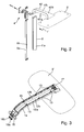
- FIG. 1 shower system shown perspectively in an assembly exploded view includes a sanitary pipe according to the invention 1, which leads from a mixer 2 to a showerhead 3 and is composed in two parts of a wall-side portion 1a and one of them substantially perpendicular abracing shower arm portion 1b.
- the two sections 1a, 1b are coupled to each other via a wall bracket 4, with which the sanitary pipe 1 can be attached to a fixed wall of a shower room in a conventional manner, so that the wall-side portion 1a substantially vertically and the shower arm portion 1b substantially horizontally extends.
- the only schematically indicated mixer 2 has in the usual way two separate water inlets 5, 6 for cold water or hot water and a quantity and temperature control, not shown, with which the user can set the amount of water and the water temperature.
- a hand shower 7 is additionally connected to the mixer 2.
- Fig. 1 If the mixing of cold water and hot water in the mixer 2 takes place, and the corresponding mixed water is passed to the hand shower 7 and the overhead shower 3.
- its wall-side portion 1a for example, made of zinc die-cast, rigid, hollow wall section line housing 8, in which a single flexible Line 9 of a bendable conduit material, such as a bendable plastic tube material or a bendable metal material, is inserted.
- the wall section conduit housing 8 has a substantially rectangular cross-section and is open along its wall side in a width which allows insertion of the flexible conduit 9 into the housing cavity so that it does not need to be inserted axially from the housing face.
- the shower arm pipe section 1b also includes a rigid hollow conduit housing 10 made, for example, as a zinc diecasting part, into which a flexible conduit, not shown, of a bendable conduit material is inserted.
- This flexible conduit discharges into the overhead shower 3 on the outlet side and is coupled on the inlet side by means of a customary line connection in the region of the wall mount 4 to the outlet-side end of the line 9 received in the wall line section 1a.
- the line housing 10 of the shower arm section 1b consists of a main body 10a and a housing wall realized here as the upper-side housing cover 10b, which is detachably attached to the main body 10a by means of screw connections 11.
- the flexble shower arm cable is inserted into the shower arm base body 10a, whereby it is correspondingly bent by approximately 90 ° in the bending area of the main body 10a.
- the bend can be made with the insertion of the flexible conduit into the housing body 10a, so that it is not necessary to prefabricate a conduit with this bend.
- After inserting the flexible line of the housing cover 10b is placed on the base body 10a and fixed by means of the screw 11 to him.
- the inserted line can be fixed by means of appropriate fixing or guiding means on the housing base body 10a or at least guided laterally.
- the shower arm duct and the wall-side duct 9 may each be provided at the end with suitable connection nipples in order to connect them to one another and / or to provide suitable connections to the overhead shower 3 on the one hand and the mixer tap 2 on the other hand.
- FIGS. 2 and 3 illustrate a variant of the shower system of Fig. 1 with the components of interest here.
- shower water is led from a mixer tap to two different shower jet areas of an overhead shower 3 '.
- the shower system of the FIGS. 2 and 3 has for this purpose a sanitary pipe according to the invention 1 'in a two-channel design.
- the sanitary pipe 1 ' consists of a wall-side section 1'a and an overhead shower-side shower arm section 1'b, which are coupled together mechanically and fluidically via a wall mount 4'.
- the wall-side section 1'a in turn includes a rigid, hollow conduit housing 8 ', which is designed to be open on its wall side, so that two parallel flexible lines 9a, 9b can be inserted from this side.
- the shower arm section 1'b comprises a rigid, hollow conduit housing 10 ', for example made of die-cast zinc, with a base body 10'a and a housing cover 10'b mounted thereon and fixed thereto.
- Fig. 3 shows the shower arm base body 10'a with mounted overhead shower 3 'in a merely design with respect to the system of Fig. 2 slightly modified version.
- the housing cover 10'b removed, which can be seen that and as in the shower arm housing main body 10'a two separate, parallel, flexible lines 12a, 12b are inserted.
- the flexible lines 12a, 12b can be fixed by means of corresponding fixing means on the housing base body 10'a.
- the flexible lines 12a, 12b are made of bendable plastic or metal material, they can easily follow a bend 14, with which the shower arm 10'a from a mounted state in a shower about vertical, entrance side course in an obliquely forward a horizontal main component.
- a connection element 15 is provided, with which the shower arm 10'a can be coupled to a wall-side line section or attached directly to a wall of a shower room.
- the flexible lines 12a, 12b terminate with a respective connection nipple 16a, 16b.
- the flexible lines 12a, 12b open into a double connection nipple 17.
- Fig. 4 shows a variant of the system of FIGS. 2 and 3 in which a sanitary line according to the invention 1 "is used, the two flexible lines 12a, 12b of bendable line material in one piece from a mixer not shown to are led to the overhead shower 3 ', wherein for better understanding of functionally equivalent, not necessarily identical elements, the same reference numerals are used as in the FIGS. 2 and 3 , In other words, the two flexible lines 12a, 12b extend for two separate spray jet areas along a wall-side section 1 "a and a subsequent shower arm section 1" b.
- the wall-side section 1 "a includes a rigid, hollow conduit housing 8" open on the wall side, which is connected to the housing base body 10'a of the shower arm section 1 "b via a connection element 15 ' Sanitary pipe 1 "on the wall of a shower room.
- the wall-side line housing 8 may be formed integrally with the housing base body 10'a of the shower arm section 1" b.
- the two flexible lines 12a, 12b are again provided with a respective connection nipple 16'a, 16'b, via which they can be connected to the mixer tap, not shown.
- a respective connection nipple 16'a, 16'b via which they can be connected to the mixer tap, not shown.
- "means 18 for guiding or fixing the two connection nipples 16'a, 16'b are provided.
- Fig. 5 It can be seen how the two parallel flexible lines 12a, 12b are accommodated closely adjacent one another and guided laterally by the webs 13 in the housing base body 10'a of the shower arm section. It shows Fig. 5 a cross-section at height just before the confluence of the two flexible lines 12a, 12b in the double connection nipple 17th
- the two-channel version of the plumbing as above to the Fig. 2 to 5 can therefore be used to separately supplied mixed shower water in a mixer tap two separate shower spray areas of a correspondingly configured shower head, which allows the establishment of different spray jet characteristics with these separate shower jet areas.
- it can be used to run cold or hot water separately or to run mixed shower water over the two ducts in a faucet parallel to a common shower jet area of the overhead shower.
- the water with twice the capacity can be compared with the use of only one line same flow cross-section lead to the shower head.
- the invention also includes multi-channel sanitary pipes with three or more fluidly parallel flexible conduits made of bendable cable material. These can be used, for example, to individually supply each of three or more separate shower spray areas of a correspondingly configured shower head with water. If necessary, corresponding multi-terminal nipples may be provided with three or more ports for the three or more flexible conduits instead of the aforementioned dual-port nipple.
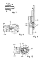
- connection nipple 19 shows in longitudinal section a connection nipple 19, as it is usable for the sanitary pipe according to the invention, for example, as the inlet-side connection nipple 16a, 16b, 16'a, 16'b in the shower systems of Fig. 2 to 4 .
- the connection nipple 19 is in an in Fig. 6 provided right area with a fir-tree hose holding profile 20 and then has a stop ring 21 thereon.
- the connection nipple 19 is inserted with its line holding profile 20 to the stop ring 21 in an associated flexible line.
- the connection nipple 19 On his in Fig. 6 left side, the connection nipple 19 has an annular groove 22 for a ring seal to be used and an outer profile 23, with which it can be performed or fixed, for example, to a housing portion of the relevant sanitary line.
- Fig. 7 shows in a longitudinal section a similar, usable for a sanitary line according to the invention nipple 19 'in an assembled position. How out Fig. 7 to recognize the nipple 19 'is inserted with a fir-tree-shaped retaining profile up to a stop ring 21' in the end of a flexible conduit 24. A surrounding ferrule member 25 secures the connection of flexible conduit 24 and nipple 19 '.
- Fig. 8 shows an embodiment in which a wall support member 26 is fastened by means of screw 27 to a hollow conduit housing portion 28 which is part of a sanitary line according to the invention and in which in turn at least one associated flexible conduit 29 is inserted from a bendable conduit material.
- the flexible line 29 is plugged onto a connection nipple 30 at the end shown.
- the screw 27 serve this same time, as from Fig. 8 can be seen to keep the connection nipple 30 in the line housing 28 and secure the connection of the flexible line 29 and nipple 30.
- FIGS. 9 and 10 illustrate an advantageous embodiment of the aforementioned double connection nipple 17 through which the two separate flexible lines 12a, 12b in the two-channel shower arm in the shower head 3 'open and can be made of a rigid plastic material, for example.
- the double connection nipple has two essentially parallel connection openings 31 a, 31 b and two corresponding outlet openings 32 a, 32 b into which one of the two connection openings 31 a, 31 b opens and which is substantially perpendicular to the connection openings 31 a, 31 b out of the nipple 17.
- the outlet opening 32a forms a central channel and the outlet opening 32b forms an annular channel.
- a substantially annular flange 33 is formed, through which the nipple 17 can be fixed to the associated shower head.
- the two separate outlet openings 32a, 32b then lead in the installed state of the nipple 17 to the various associated shower jet areas of the overhead shower.
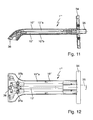
- FIGS. 11 and 12 illustrate as a further embodiment of the invention a sanitary conduit formed as a directly wall-mountable shower arm 1 '"For this purpose, the shower arm 1'" in a rear end region on a mounting plate 34, with which it can be attached directly to a shower room wall to mounted state substantially horizontally projecting from this wall. Towards the rear, the shower arm 1 '"protrudes beyond the mounting plate 34 with a connecting pipe piece 35, via which it can be connected to a connection in the wall of a flush-mounted water supply.
- the shower arm 1 ' includes a hollow, for example made of zinc diecast line housing 10" with a base 10 "a and a releasably attached to this housing wall, which here forms a lower-side housing cover 10" b.
- the hollow conduit housing 10 is a flexible conduit 12 'made of bendable plastic or metal material inserted, being fluid-tightly inserted with its rear end into the connecting pipe piece 35. With its front end, it opens into a shower head outlet 36 of the shower arm 1"' , As in particular from the bottom view of Fig.
- the shower arm 1 ' is prefabricated with two further outlets 37a, 37b, which in the present case remain unused In alternative applications of this shower arm 1'", these other outlets 37a, 37b can also each have a flexible duct in the manner of the flexible duct Be assigned 12 ', which are then additionally inserted into the hollow line housing 10 " then, for example, three different shower jet areas of a front of the shower arm 1 '"coupled shower head can be individually supplied with water.
- the invention provides a sanitary pipe, which is suitable, inter alia, as shower spout for showerhead systems.
- a sanitary pipe which is suitable, inter alia, as shower spout for showerhead systems.
- one or more flexible lines of a bendable cable material which are inserted into a rigid, hollow line housing.
- the sanitary pipe according to the invention can be manufactured with significantly lower weight.
- any contact of the water carried with metal material of a line housing can be avoided with the sanitary pipe according to the invention.
- sanitary pipe according to the invention can also be used for other applications in sanitary engineering, in which the said properties are desirable.
- the line housing for the sanitary line according to the invention can be produced with relatively little effort, for example, as a zinc die-cast part.
Landscapes
- Health & Medical Sciences (AREA)
- Life Sciences & Earth Sciences (AREA)
- Engineering & Computer Science (AREA)
- Hydrology & Water Resources (AREA)
- Public Health (AREA)
- Water Supply & Treatment (AREA)
- Bathtubs, Showers, And Their Attachments (AREA)
- Nozzles (AREA)
- Domestic Plumbing Installations (AREA)
- Paper (AREA)
Abstract
Description
- Die Erfindung bezieht sich auf eine Sanitärleitung, wie sie insbesondere als Brausearmleitung für eine Duschbrause verwendbar ist.
- Ein gängiger Typ von Brausearm ist ein hohler Brausearm aus Messing, dessen Hohlkanal als wasserführender Kanal zu einem daran montierten Brausekopf fungiert. Derartige Brausearme aus einem Messinggehäuse haben ein relativ hohes Gewicht. Das durchgeführte Wasser kommt direkt mit dem Messinggehäusematerial in Kontakt.
- Der Erfindung liegt als technisches Problem die Bereitstellung einer Sanitärleitung zugrunde, die sich mit vergleichsweise geringem Gewicht realisieren lässt und mit der sich ein Kontakt von durchgeführtem Wasser zu einem Gehäusemetall vermeiden lässt.
- Die Erfindung löst dieses Problem durch die Bereitstellung einer Sanitärleitung mit den Merkmalen des Anspruchs 1. Diese Sanitärleitung weist ein starres, hohles Leitungsgehäuse mit einem Grundkörper und einer an diesem angebrachten Gehäusewand auf. In das hohle Leitungsgehäuse ist mindestens eine flexible Leitung aus einem biegefähigen Leitungsmaterial eingelegt.
- Das Einlegen der flexiblen Leitung in das hohle Leitungsgehäuse kann problemlos vor dem Schließen des Leitungsgehäuses durch Anbringen der Gehäusewand am Grundkörper erfolgen. Die eingelegte Leitung fungiert als wasserführender Kanal und vermeidet für das durchgeführte Wasser jeglichen Kontakt mit dem typischerweise metallischen Material des Leitungsgehäuses. So kann das Leitungsgehäuse beispielsweise als hohles Zinkdruckgussteil gefertigt sein. Von besonderem Vorteil ist die Verwendung von biegefähigem Material für die eingelegte Leitung. Denn dadurch kann die Leitung flexibel einem beliebigen, z.B. gekrümmten bzw. abgewinkelten Verlauf des Leitungsgehäuses folgen, ohne dass sie dafür vorab in ihrer Form und Länge exakt auf die Form des Leitungsgehäuses abgestimmt werden muss, wie dies bei einer alternativ denkbaren Verwendung eines starren Rohrteils aus Metall oder Kunststoff der Fall wäre.
- Vorteilhafte alternative Weiterbildungen der Erfindung beinhalten die Verwendung einer biegefähigen Kunststoffschlauchleitung oder einer biegefähigen Metallleitung für die flexible Leitung.
- In einer Weiterbildung der Erfindung besitzt die Sanitärleitung Mittel zum Fixieren oder seitlichen Führen der jeweiligen flexiblen Leitung. Auf diese Weise kann die Leitung in definierter Lage im Leitungsgehäuse gehalten werden.
- In einer Weiterbildung der Erfindung weist die Sanitärleitung an wenigstens einem Ende der flexiblen Leitung einen Anschlussnippel auf, der vorzugsweise aus einem starren Kunststoff- oder Metallmaterial besteht.
- In einer Weiterbildung der Erfindung sind mehrere flexible Leitungen strömungstechnisch parallel und nebeneinanderliegend im Leitungsgehäuse angeordnet. Dadurch können beispielsweise Warmwasser und Kaltwasser getrennt in der Sanitärleitung geführt werden, oder es kann Duschwasser separat zu getrennten Brausestrahlbereichen einer angekoppelten Duschbrause geführt werden. In einer weiteren Ausgestaltung ist ein Multianschlussnippel vorgesehen, der mehrere Anschlussöffnungen aufweist, die mit einem Ende je einer der flexiblen Leitungen gekoppelt sind. Die Anschlussöffnungen sind strömungstechnisch mit einer gemeinsamen Austritts- oder Eintrittsöffnung oder alternativ mit getrennten Austritts- oder Eintrittsöffnungen des Multianschlussnippels verbunden. Im erstgenannten Fall kann über die Eintrittsöffnung zugeführtes Wasser auf die mehreren angeschlossenen flexiblen Leitungen aufgeteilt oder über die flexiblen Leitungen getrennt zugeführtes Wasser im Multianschlussnippel zusammengebracht werden. Im letztgenannten Fall kann über die Austrittsöffnungen Wasser separat getrennten Brausestrahlbereichen zugeführt werden.
- In einer vorteilhaften Weiterbildung der Erfindung beinhaltet die Sanitärleitung eine Brausearmleitung für eine Duschbrause. In einer weiteren Ausgestaltung bildet bei einer solchen Brausearmleitung der Multianschlussnippel einen Anschluss für die angekoppelten flexiblen Leitungen an einen Brausekopf der Duschbrause.
- In einer Ausgestaltung der Erfindung ist von den mehreren, strömungstechnisch parallelen flexiblen Leitungen eine erste an einen ersten Brausestrahlbereich der Duschbrause und eine zweite an einen vom ersten getrennten zweiten Brausestrahlbereich ankoppelbar. Dies ermöglicht eine getrennte Führung von Duschwasser in der Sanitärleitung zu den verschiedenen Brausestrahlbereichen. Wenn austrittsseitig der Multianschlussnippel vorgesehen ist, können über diesen die flexiblen Leitungen an die getrennten Brausebereiche angekoppelt werden.
- In einer weiteren Ausgestaltung der Erfindung weist die Sanitärleitung zum Einsatz bei einer Duschbrause einen duschwandseitigen Abschnitt und einen gegenüber diesem abgewinkelt verlaufenden Brausearmabschnitt auf. So kann der duschwandseitige Abschnitt z.B. dafür vorgesehen sein, im Wesentlichen vertikal verlaufend an einer festen Wand einer Dusche montiert zu werden, während der Brausearmabschnitt davon im Wesentlichen horizontal verlaufend absteht und den Brausekopf trägt.
- Vorteilhafte Ausführungsformen der Erfindung sind in den Zeichnungen dargestellt und werden nachfolgend beschrieben. Hierbei zeigen:
- Fig. 1
- eine perspektivische Montage-Explosionsansicht eines Duschbrausensystems mit einkanaliger Kopfbrausen-Wasserzufuhr,
- Fig. 2
- eine perspektivische Montage-Explosionsansicht eines Teils einer Variante des Duschbrausensystems von
Fig. 1 mit zweikanaliger Kopfbrausen-Wasserzufuhr, - Fig. 3
- eine Perspektivansicht auf einen Brausearm mit montierter Kopfbrause des Duschbrausensystems von
Fig. 2 bei abgenommenem Brausearmdeckel, - Fig. 4
- eine Perspektivansicht einer Variante des Duschbrausensystems von
Fig. 2 in einer Wandstange-Brausearm-Ausführung bei abgenommenem Brausearmdeckel, - Fig. 5
- eine Querschnittansicht durch den Brausearm längs einer Linie V-V von
Fig. 3 , - Fig. 6
- eine Längsschnittansicht durch einen für eine Brausearmleitung der Duschbrausensysteme der
Fig. 1 bis 4 verwendbaren Anschlussnippel, - Fig. 7
- eine Längsschnittansicht einer Leitungs-Anschlussnippel-Kopplung,
- Fig. 8
- eine Längsschnittansicht einer für die Systeme der
Fig. 1 bis 7 verwendbaren Wandhalterung, - Fig. 9
- eine Draufsicht von oben auf einen z.B. für die Systeme der
Fig. 2 bis 5 mit zweikanaliger Wasserzufuhr verwendbaren Doppelanschlussnippel, - Fig. 10
- eine Draufsicht von unten auf den Doppelanschlussnippel von
Fig. 9 , - Fig. 11
- eine Längsschnittansicht einer Sanitärleitung, die als direkt wandmontierbarer Brausearm ausgeführt ist, und
- Fig. 12
- eine Ansicht von unten auf den Brausearm von
Fig. 11 bei abgenommenem Gehäusedeckel. - Das in
Fig. 1 perspektivisch in einer Montage-Explosionsansicht dargestellte Duschbrausensystem beinhaltet eine erfindungsgemäße Sanitärleitung 1, die von einer Mischbatterie 2 zu einer Kopfbrause 3 führt und sich zweiteilig aus einem wandseitigen Abschnitt 1a und einem davon im Wesentlichen senkrecht abkragenden Brausearmabschnitt 1b zusammensetzt. Die beiden Abschnitte 1a, 1b werden über eine Wandhalterung 4 miteinander gekoppelt, mit der die Sanitärleitung 1 an einer festen Wand eines Duschraums in üblicher Weise befestigt werden kann, so dass sich der wandseitige Abschnitt 1a im Wesentlichen vertikal und der Brausearmabschnitt 1 b im Wesentlichen horizontal erstreckt. - Die hier nur schematisch angedeutete Mischbatterie 2 besitzt in üblicher Weise zwei getrennte Wasserzuläufe 5, 6 für Kaltwasser bzw. Warmwasser und eine nicht gezeigte Mengen- und Temperaturregelung, mit welcher der Benutzer die Wassermenge und die Wassertemperatur einstellen kann. In herkömmlicher Weise ist an die Mischbatterie 2 zusätzlich eine Handbrause 7 angeschlossen.
- Im Ausführungsbeispiel von
Fig. 1 findet die Vermischung von Kaltwasser und Warmwasser in der Mischbatterie 2 statt, und das entsprechende Mischwasser wird zur Handbrause 7 bzw. zur Kopfbrause 3 geführt. Die Zuführung zur Kopfbrause 3 erfolgt durch die in diesem Fall entsprechend einkanalig ausgeführte Sanitärleitung 1. Dazu weist ihr wandseitiger Abschnitt 1a ein zum Beispiel aus Zinkdruckguss gefertigtes, starres, hohles Wandabschnitt-Leitungsgehäuse 8 auf, in das eine einzelne flexible Leitung 9 aus einem biegefähigen Leitungsmaterial, wie einem biegefähigen Kunststoffschlauchmaterial oder einem biegefähigen Metallmaterial, eingelegt ist. Das Wandabschnitt-Leitungsgehäuse 8 weist einen im Wesentlichen rechteckigen Querschnitt auf und ist längs seiner Wandseite in einer Breite offen, die das Einbringen der flexiblen Leitung 9 in den Gehäusehohlraum ermöglicht, so dass sie nicht axial von der Gehäusestirnseite her eingeschoben werden braucht. - Der Brausearm-Leitungsabschnitt 1b beinhaltet ebenso ein starres, hohles, zum Beispiel als Zinkdruckgussteil gefertigtes Leitungsgehäuse 10, in das eine nicht gezeigte flexible Leitung aus einem biegefähigen Leitungsmaterial eingelegt ist. Diese flexible Leitung mündet austrittsseitig in die Kopfbrause 3 und wird eintrittsseitig mittels einer üblichen Leitungsverbindung im Bereich der Wandhalterung 4 mit dem austrittsseitigen Ende der im Wandleitungsabschnitt 1a aufgenommenen Leitung 9 gekoppelt.
- Das Leitungsgehäuse 10 des Brausearmabschnitts 1 b besteht aus einem Grundkörper 10a und einer hier als oberseitiger Gehäusedeckel 10b realisierten Gehäusewand, die mittels Schraubverbindungen 11 lösbar am Grundkörper 10a angebracht ist. Die flexble Brausearm-Leitung wird bei abgenommenem Gehäusedeckel 10b in den Brausearm-Grundkörper 10a eingelegt, wobei sie im Abwinklungsbereich des Grundkörpers 10a entsprechend um ca. 90° umgebogen wird. Durch die Verwendung von biegefähigem Leitungsmaterial kann die Biegung mit dem Einlegen der flexiblen Leitung in den Gehäusegrundkörper 10a hergestellt werden, so dass es nicht erforderlich ist, eine Leitung mit dieser Biegung vorzufertigen. Nach dem Einlegen der flexiblen Leitung wird der Gehäusedeckel 10b auf den Grundkörper 10a aufgesetzt und mittels der Schraubverbindungen 11 an ihm fixiert. Je nach Bedarf kann die eingelegte Leitung durch entsprechende Fixier- oder Führungsmittel am Gehäusegrundkörper 10a fixiert oder wenigstens seitlich geführt werden. Die Brausearm-Leitung und die wandseitige Leitung 9 können endseitig jeweils mit geeigneten Anschlussnippeln versehen sein, um sie miteinander zu verbinden und/oder geeignete Anschlüsse an die Kopfbrause 3 einerseits und die Mischbatterie 2 andererseits bereitzustellen.
- Die
Fig. 2 und 3 veranschaulichen eine Variante des Duschsystems vonFig. 1 mit den hier interessierenden Komponenten. Bei dieser Systemvariante wird Duschwasser von einer Mischbatterie getrennt zu zwei verschiedenen Brausestrahlbereichen einer Kopfbrause 3' geführt. Das Duschsystem derFig. 2 und 3 weist dazu eine erfindungsgemäße Sanitärleitung 1' in einer zweikanaligen Ausführung auf. Ähnlich dem System vonFig. 1 besteht die Sanitärleitung 1' aus einem wandseitigen Abschnitt 1'a und einem kopfbrausenseitigen Brausearmabschnitt 1'b, die miteinander mechanisch und strömungstechnisch über eine Wandhalterung 4' gekoppelt sind. Der wandseitige Abschnitt 1'a beinhaltet wiederum ein starres, hohles Leitungsgehäuse 8', das an seiner Wandseite offen ausgebildet ist, so dass von dieser Seite her zwei parallele flexible Leitungen 9a, 9b eingelegt werden können. - Analog beinhaltet der Brausearmabschnitt 1'b ein starres, hohles Leitungsgehäuse 10', zum Beispiel aus Zinkdruckguss, mit einem Grundkörper 10'a und einem aufgesetzten und daran fixierten Gehäusedeckel 10'b.
Fig. 3 zeigt den Brausearm-Grundkörper 10'a mit montierter Kopfbrause 3' in einer lediglich gestalterisch gegenüber dem System vonFig. 2 leicht modifizierten Version. In der Ansicht vonFig. 3 ist der Gehäusedeckel 10'b abgenommen, wodurch zu erkennen ist, dass und wie in den Brausearmgehäuse Grundkörper 10'a zwei getrennte, parallele, flexible Leitungen 12a, 12b eingelegt sind. Dabei sind sie seitlich durch Stege 13 geführt, die an inneren Seitenwänden des Gehäusegrundkörpers 10'a paarweise gegenüberliegend ausgebildet sind und bei Bedarf auch Schrauböffnungen bereitstellen, in welche Schrauben z.B. zur Befestigung des Gehäusedeckels 10'b eingeschraubt werden können. Zusätzlich oder alternativ können die flexiblen Leitungen 12a, 12b durch entsprechende Fixiermittel am Gehäusegrundkörper 10'a festgelegt werden. - Da die flexiblen Leitungen 12a, 12b aus biegefähigem Kunststoff- oder Metallmaterial gefertigt sind, können sie problemlos einer Biegung 14 folgen, mit welcher der Brausearm 10'a von einem im montierten Zustand in einer Dusche etwa vertikalen, eintrittsseitigen Verlauf in einen schräg nach vorn mit einer horizontalen Hauptkomponente gerichteten Verlauf übergeht. Am eintrittsseitigen Ende des Brausearms 10'a ist in der in
Fig. 3 gezeigten Variante ein Anschlusselement 15 vorgesehen, mit dem der Brausearm 10'a an einen wandseitigen Leitungsabschnitt angekoppelt oder direkt an einer Wand eines Duschraums befestigt werden kann. An diesem eintrittsseitigen Ende schließen die flexiblen Leitungen 12a, 12b mit je einem Anschlussnippel 16a, 16b ab. Am entgegengesetzten, kopfbrausenseitigen Ende münden die flexiblen Leitungen 12a, 12b in einen Doppelanschlussnippel 17. -
Fig. 4 zeigt eine Variante des Systems derFig. 2 und 3 , bei welcher eine erfindungsgemäße Sanitärleitung 1" verwendet ist, deren beide flexible Leitungen 12a, 12b aus biegefähigem Leitungsmaterial einstückig von einer nicht gezeigten Mischbatterie bis zur Kopfbrause 3' geführt sind, wobei zum besseren Verständnis für funktionell äquivalente, nicht zwingend identische Elemente gleiche Bezugszeichen verwendet sind wie in denFig. 2 und 3 . Mit anderen Worten erstrecken sich die beiden flexiblen Leitungen 12a, 12b für zwei getrennte Brausestrahlbereiche längs eines wandseitigen Abschnitts 1"a und eines anschließenden Brausearmabschnitts 1"b. Der wandseitige Abschnitt 1"a beinhaltet dazu ein wandseitig offenes, starres, hohles Leitungsgehäuse 8", das über ein Verbindungselement 15' mit dem Gehäusegrundkörper 10'a des Brausearmabschnitts 1"b verbunden ist. Das Verbindungselement 15' dient gleichzeitig als Wandhalter zur Befestigung der Sanitärleitung 1" an der Wand eines Duschraums. Alternativ kann das wandseitige Leitungsgehäuse 8" einteilig mit dem Gehäusegrundkörper 10'a des Brausearmabschnitts 1"b gebildet sein. - Am eintrittsseitigen Ende sind die beiden flexiblen Leitungen 12a, 12b wiederum mit je einem Anschlussnippel 16'a, 16'b versehen, über die sie an die nicht gezeigte Mischbatterie angeschlossen werden können. Am entsprechenden Endbereich des wandseitigen Leitungsgehäuses 8" sind Mittel 18 zur Führung oder Fixierung der beiden Anschlussnippel 16'a, 16'b vorgesehen.
- Aus
Fig. 5 ist zu erkennen, wie die beiden parallelen flexiblen Leitungen 12a, 12b eng aneinanderliegend und seitlich durch die Stege 13 geführt im Gehäusegrundkörper 10'a des Brausearmabschnitts aufgenommen sind. Dabei zeigtFig. 5 einen Querschnitt auf Höhe kurz vor Einmündung der beiden flexiblen Leitungen 12a, 12b in den Doppelanschlussnippel 17. - Die zweikanalige Ausführung der Sanitärleitung, wie oben zu den
Fig. 2 bis 5 beschreiben, kann somit dazu genutzt werden, in einer Mischbatterie gemischtes Duschwasser getrennt zwei separaten Brausestrahlbereichen eines entsprechend konfigurierten Brausekopfes zuzuführen, der mit diesen separaten Brausestrahlbereichen die Einstdlung unterschiedlicher Brausestrahlcharakteristiken ermöglicht. Alternativ kann sie dazu verwendet werden, Kaltwasser oder Warmwasser getrennt zu führen oder in einer Mischbatterie gemischtes Duschwasser über die beiden Leitungskanäle parallel zu einem gemeinsamen Brausestrahlbereich der Kopfbrause zu führen. Im letzteren Fall lässt sich das Wasser mit doppelter Mengenkapazität verglichen mit der Verwendung nur einer Leitung gleichen Durchflussquerschnitts zum Brausekopf führen. - Es versteht sich, dass die Erfindung auch mehrkanalige Sanitärleitungen mit drei oder mehr strömungstechnisch parallelen flexiblen Leitungen aus biegefähigem Leitungsmaterial umfasst. Diese lassen sich beispielsweise dazu verwenden, jeden von drei oder mehr separaten Brausestrahlbereichen eines entsprechend konfigurierten Brausekopfes individuell mit Wasser zu versorgen. Bei Bedarf können entsprechende Multianschlussnippel mit drei oder mehr Anschlussöffnungen für die drei oder mehr flexiblen Leitungen anstelle des erwähnten Doppelanschlussnippels vorgesehen sein.
-
Fig. 6 zeigt im Längsschnitt einen Anschlussnippel 19, wie er für die erfindungsgemäße Sanitärleitung verwendbar ist, beispielsweise als die eintrittsseitigen Anschlussnippel 16a, 16b, 16'a, 16'b in den Duschsystemen derFig. 2 bis 4 . Der Anschlussnippel 19 ist in einem inFig. 6 rechten Bereich mit einem tannenbaumartigen Schlauchhalteprofil 20 versehen und weist anschließend daran einen Anschlagring 21 auf. Der Anschlussnippel 19 wird mit seinem Leitungshalteprofil 20 bis zum Anschlagring 21 in eine zugehörige flexible Leitung eingesteckt. Auf seiner inFig. 6 linken Seite weist der Anschlussnippel 19 eine Ringnut 22 für eine einzusetzende Ringdichtung und ein Außenprofil 23 auf, mit dem er zum Beispiel an einem Gehäusebereich der betreffenden Sanitärleitung geführt oder fixiert werden kann. -
Fig. 7 zeigt in einem Längsschnitt einen ähnlichen, für eine erfindungsgemäße Sanitärleitung verwendbaren Anschlussnippel 19' in einer montierten Position. Wie ausFig. 7 zu erkennen, ist der Nippel 19' mit einem tannenbaumförmigen Halteprofil bis zu einem Anschlagring 21' in das Ende einer flexiblen Leitung 24 eingesteckt. Ein umgebendes Klemmhülsenelement 25 sichert die Verbindung von flexibler Leitung 24 und Anschlussnippel 19'. -
Fig. 8 zeigt ein Ausführungsbeispiel, bei dem ein Wandhalterelement 26 mittels Schraubverbindungen 27 an einem hohlen Leitungsgehäuseabschnitt 28 befestigt ist, der Teil einer erfindungsgemäßen Sanitärleitung ist und in den wiederum mindestens eine zugehörige flexible Leitung 29 aus einem biegefähigen Leitungsmaterial eingelegt ist. Die flexible Leitung 29 ist am gezeigten Ende auf einen Anschlussnippel 30 aufgesteckt. Die Schraubverbindungen 27 dienen hierbei gleichzeitig, wie ausFig. 8 ersichtlich, dazu, den Anschlussnippel 30 im Leitungsgehäuse 28 zu halten und die Verbindung von flexibler Leitung 29 und Anschlussnippel 30 zu sichern. - Die
Fig. 9 und 10 veranschaulichen eine vorteilhafte Ausführung für den erwähnten Doppelanschlussnippel 17, über den die beiden getrennten flexiblen Leitungen 12a, 12b bei der zweikanaligen Brausearmausführung in den Brausekopf 3' münden und der z.B. aus einem biegesteifen Kunststoffmaterial gefertigt sein kann. Wie daraus ersichtlich, weist der Doppelanschlussnippel zwei im Wesentlichen parallel verlaufende Anschlussöffnungen 31 a, 31 b und zwei korrespondierende Austrittsöffnungen 32a, 32b auf, in welche je eine der beiden Anschlussöffnungen 31 a, 31b mündet und die im Wesentlichen senkrecht zu den Anschlussöffnungen 31a, 31 b aus dem Nippel 17 ausmünden. Dabei bildet die Austrittsöffnung 32a einen mittigen Kanal und die Austrittsöffnung 32b einen ringförmigen Kanal. An dem Doppelanschlussnippel 17 ist ein im Wesentlichen ringförmiger Flansch 33 angeformt, durch den der Nippel 17 am zugeordneten Brausekopf festgelegt werden kann. Die beiden getrennten Austrittsöffnungen 32a, 32b führen dann im eingebauten Zustand des Nippels 17 zu den verschiedenen zugehörigen Brausestrahlbereichen der Kopfbrause. - Die
Fig. 11 und 12 veranschaulichen als ein weiteres Ausführungsbeispiel der Erfindung eine Sanitärleitung, die als direkt wandmontierbarer Brausearm 1'" ausgebildet ist. Dazu weist der Brausearm 1'" in einem hinteren Endbereich eine Montageplatte 34 auf, mit der er direkt an einer Duschraumwand befestigt werden kann, um im montierten Zustand im Wesentlichen horizontal von dieser Wand vorzustehen. Nach hinten ragt der Brausearm 1'" mit einem Anschlussrohrstück 35 über die Montageplatte 34 hinaus, über das er an einen in der Wand liegenden Anschluss einer Unterputz-Wasserzuführung anschließbar ist. - Der Brausearm 1'" beinhaltet ein hohles, zum Beispiel aus Zinkdruckguss gefertigtes Leitungsgehäuse 10" mit einem Grundkörper 10"a und einer an diesem lösbar angebrachten Gehäusewand, die hier einen unterseitigen Gehäusedeckel 10"b bildet. In das hohle Leitungsgehäuse 10" ist eine flexible Leitung 12' aus biegefähigem Kunststoff- oder Metallmaterial eingelegt, wobei sie mit ihrem hinteren Ende in das Anschlussrohrstück 35 fluiddicht eingefügt ist. Mit ihrem vorderen Ende mündet sie in einen brausekopfseitigen Auslass 36 des Brausearms 1"'. Wie insbesondere aus der Unterseitenansicht von
Fig. 12 zu erkennen, ist der Brausearm 1'" mit zwei weiteren Auslässen 37a, 37b vorgefertigt, die im vorliegenden Fall unbenutzt bleiben. In alternativen Anwendungen dieses Brausearms 1'" können diesen weiteren Auslässen 37a, 37b ebenfalls je eine flexible Leitung nach Art der flexiblen Leitung 12' zugeordnet sein, die dann zusätzlich in das hohle Leitungsgehäuse 10" eingelegt werden. Dadurch können dann z.B. drei verschiedene Brausestrahlbereiche einer vorne an dem Brausearm 1'" angekoppelten Kopfbrause individuell mit Wasser versorgt werden. - Wie die gezeigten und oben erläuterten Ausführungsbeispiele deutlich machen, stellt die Erfindung eine Sanitärleitung bereit, die sich unter anderem als Brausearmleitung für Duschbrausensysteme eignet. Zur Wasserführung dienen bei der erfindungsgemäßen Sanitärleitung eine oder mehrere flexible Leitungen aus einem biegefähigen Leitungsmaterial, die in ein starres, hohles Leitungsgehäuse eingelegt sind. Verglichen mit herkömmlichen Sanitärleitungen aus einem Messingkörper mit wasserführendem Hohlkanal lässt sich die erfindungsgemäße Sanitärleitung mit deutlich geringerem Gewicht fertigen. Zudem lässt sich mit der erfindungsgemäßen Sanitärleitung jeglicher Kontakt des durchgeführten Wassers mit Metallmaterial eines Leitungsgehäuses vermeiden. Die Bereitstellung entsprechender Brausearme für Duschsysteme stellt eine besonders vorteilhafte Einsatzmöglichkeit der Erfindung dar, es versteht sich jedoch, dass sich die erfindungsgemäße Sanitärleitung auch für andere Anwendungen in der Sanitärtechnik einsetzen lässt, in denen die genannten Eigenschaften erwünscht sind. Das Leitungsgehäuse für die erfindungsgemäße Sanitärleitung lässt sich mit relativ geringem Aufwand zum Beispiel als Zinkdruckgussteil herstellen.
Claims (10)
- Sanitärleitung, insbesondere für eine Duschbrause, mit- einem starren, hohlen Leitungsgehäuse (10, 10', 10"), das einen Grundkörper (10a, 10'a, 10"a) und eine an diesem lösbar angebrachte Gehäusewand (10b, 10'b, 10"b) aufweist, und- mindestens einer in dem hohlen Leitungsgehäuse eingelegten, flexiblen Leitung (9, 9a, 9b, 12') aus einem biegefähigen Leitungsmaterial.
- Sanitärleitung nach Anspruch 1, weiter dadurch gekennzeichnet, dass die flexble Leitung eine biegefähige Kunststoffschlauchleitung oder eine biegefähige Metallleitung ist.
- Sanitärleitung nach Anspruch 1 oder 2, weiter gekennzeichnet durch Mittel (13, 18, 27) zum Fixieren oder seitlichen Führen der mindestens einen Leitung im Leitungsgehäuse.
- Sanitärleitung nach einem der Ansprüche 1 bis 3, weiter gekennzeichnet durch wenigstens einen Anschlussnippel (16a, 16b, 17), der mit einem Ende der wenigstens einen Leitung gekoppelt ist.
- Sanitärleitung nach einem der Ansprüche 1 bis 4, weiter dadurch gekennzeichnet, dass mehrere flexible Leitungen (9a, 9b) strömungstechnisch parallel und im Leitungsgehäuse nebeneinander angeordnet sind.
- Sanitärleitung nach Anspruch 5, weiter gekennzeichnet durch einen Multianschlussnippel (17) mit mehreren Anschlussöffnungen (31 a, 31 b), die mit einem Ende je einer der flexiblen Leitungen gekoppelt sind, und mit einer den Anschlussöffnungen gemeinsamen Austritts- oder Eintrittsöffnung oder mit getrennten Austritts- oder Eintrittsöffnungen (21 a, 32b) für die Anschlussöffnungen.
- Sanitärleitung nach einem der Ansprüche 1 bis 6, weiter dadurch gekennzeichnet, dass sie eine Brausearmleitung einer Duschbrause beinhaltet.
- Sanitärleitung nach Anspruch 7, weiter dadurch gekennzeichnet, dass der Multianschlussnippel einen Anschluss für die angekoppelten flexiblen Leitungen an einen Brausekopf der Duschbrause bildet.
- Sanitärleitung nach Anspruch 7 oder 8, weiter dadurch gekennzeichnet, dass von den mehreren flexiblen Leitungen eine erste Leitung an einen ersten Brausestrahlbereich der Duschbrause und eine zweite Leitung an einen vom ersten getrennten zweiten Brausestrahlbereich der Duschbrause ankoppelbar ist.
- Sanitärleitung nach Anspruch 8 oder 9, weiter dadurch gekennzeichnet, dass sie zur Verwendung bei einer Duschbrause einen duschwandseitigen Abschnitt (1a, 1'a, 1 "a) und einen gegenüber diesem abgewinkelt verlaufenden Brausearmabschnitt (1b, 1'b, 1"b) aufweist.
Applications Claiming Priority (1)
| Application Number | Priority Date | Filing Date | Title |
|---|---|---|---|
| DE201310203946 DE102013203946A1 (de) | 2013-03-07 | 2013-03-07 | Sanitärleitung, insbesondere für eine Duschbrause |
Publications (2)
| Publication Number | Publication Date |
|---|---|
| EP2775042A1 true EP2775042A1 (de) | 2014-09-10 |
| EP2775042B1 EP2775042B1 (de) | 2023-04-05 |
Family
ID=50193357
Family Applications (1)
| Application Number | Title | Priority Date | Filing Date |
|---|---|---|---|
| EP14157879.9A Active EP2775042B1 (de) | 2013-03-07 | 2014-03-05 | Zuleitung zur Kopfdusche einer Dusche |
Country Status (5)
| Country | Link |
|---|---|
| US (1) | US9297151B2 (de) |
| EP (1) | EP2775042B1 (de) |
| CN (1) | CN104033663B (de) |
| DE (1) | DE102013203946A1 (de) |
| ES (1) | ES2948377T3 (de) |
Families Citing this family (11)
| Publication number | Priority date | Publication date | Assignee | Title |
|---|---|---|---|---|
| CN106993966B (zh) * | 2017-04-20 | 2023-04-21 | 鹤山市洁利雅实业有限公司 | 一种靠墙式淋浴管 |
| USD960302S1 (en) | 2017-06-28 | 2022-08-09 | Phoenix Industries Pty Ltd | Shower head |
| JP1646775S (de) * | 2019-01-31 | 2019-12-02 | ||
| USD939046S1 (en) | 2019-02-22 | 2021-12-21 | Phoenix Industries Pty Ltd | Hand shower |
| USD943709S1 (en) | 2019-02-22 | 2022-02-15 | Phoenix Industries Pty Ltd | Twin showers |
| USD942599S1 (en) | 2019-02-22 | 2022-02-01 | Phoenix Industries Pty Ltd | Hand shower bracket |
| USD954900S1 (en) | 2019-02-22 | 2022-06-14 | Phoenix Industries Pty Ltd | Rail shower |
| USD972922S1 (en) | 2019-02-22 | 2022-12-20 | Phoenix Industries Pty Ltd | Hand shower bracket |
| USD939047S1 (en) * | 2019-02-22 | 2021-12-21 | Phoenix Industries Pty Ltd | Rail shower |
| USD939664S1 (en) | 2019-02-22 | 2021-12-28 | Phoenix Industries Pty Ltd | Hand shower |
| USD923143S1 (en) * | 2019-08-20 | 2021-06-22 | Fujian Xihe Sanitary Ware Technology Co., Ltd. | Slidable shower holder |
Citations (7)
| Publication number | Priority date | Publication date | Assignee | Title |
|---|---|---|---|---|
| US3333284A (en) * | 1964-12-30 | 1967-08-01 | Symmons Engineering Company | Plumbing fixture |
| WO1993008724A1 (en) * | 1991-11-08 | 1993-05-13 | Kohler Co. | Shower enclosure assembly |
| FR2692465A1 (fr) * | 1992-06-19 | 1993-12-24 | Int Hydro Produit | Colonne de douche anti-vandalisme. |
| WO1998002077A1 (en) * | 1996-07-13 | 1998-01-22 | Daryl Industries Limited | Shower apparatus comprising multiple shower heads and diverter |
| EP1589154A2 (de) * | 2004-04-23 | 2005-10-26 | Archedes S.r.l. | Multifunktionale Einheit für Sanitärarmaturen |
| US20090320203A1 (en) * | 2008-06-27 | 2009-12-31 | Jeff Chen | Control module for multi-nozzle shower |
| US20100276020A1 (en) * | 2009-04-29 | 2010-11-04 | Fan kun-jing | Shower rod assembly |
Family Cites Families (12)
| Publication number | Priority date | Publication date | Assignee | Title |
|---|---|---|---|---|
| DE3434735A1 (de) * | 1984-09-21 | 1986-04-03 | High Tech Ausbau- und Einrichtungsprodukte Vertriebsgesellschaft mbH, 8000 München | Schlauch fuer sanitaerarmaturen mit abnehmbarem griffstueck und sanitaerarmatur |
| US5121511A (en) * | 1989-11-27 | 1992-06-16 | Matsushita Electric Works, Ltd. | Shower device |
| US5365620A (en) * | 1993-07-26 | 1994-11-22 | Macleod Robert P | Outdoor shower apparatus |
| GB9318302D0 (en) * | 1993-09-03 | 1993-10-20 | Jing Mei Ind Ltd | Shower head |
| DE19721587B4 (de) * | 1997-05-23 | 2009-06-04 | Hansgrohe Ag | Mehrfachduschkombination |
| US5983419A (en) * | 1998-07-14 | 1999-11-16 | Carroll; Jon Robert | Outdoor shower and spigot apparatus |
| ITTO20050251A1 (it) * | 2005-04-14 | 2006-10-15 | Aqvadesign S R L | Doccia monoblocco |
| US7657949B2 (en) * | 2007-06-01 | 2010-02-09 | Sam Zhadanov | Hollow shower panel |
| ITMN20080006A1 (it) * | 2008-03-07 | 2009-09-08 | A Q A S R L | Doccia per bagno |
| US20100024909A1 (en) * | 2008-07-30 | 2010-02-04 | Lu Zhong Ping | Adjustable rod structure |
| DE102010024106A1 (de) * | 2010-06-17 | 2011-12-22 | Tece Gmbh | Multifunktionales Duschpaneel |
| US8684039B2 (en) * | 2011-08-19 | 2014-04-01 | Xiamen Lelin Sanitary Ware Co., Ltd. | Shower assembly with supporting arm |
-
2013
- 2013-03-07 DE DE201310203946 patent/DE102013203946A1/de not_active Ceased
-
2014
- 2014-03-05 EP EP14157879.9A patent/EP2775042B1/de active Active
- 2014-03-05 ES ES14157879T patent/ES2948377T3/es active Active
- 2014-03-07 US US14/200,092 patent/US9297151B2/en not_active Expired - Fee Related
- 2014-03-07 CN CN201410081951.6A patent/CN104033663B/zh active Active
Patent Citations (7)
| Publication number | Priority date | Publication date | Assignee | Title |
|---|---|---|---|---|
| US3333284A (en) * | 1964-12-30 | 1967-08-01 | Symmons Engineering Company | Plumbing fixture |
| WO1993008724A1 (en) * | 1991-11-08 | 1993-05-13 | Kohler Co. | Shower enclosure assembly |
| FR2692465A1 (fr) * | 1992-06-19 | 1993-12-24 | Int Hydro Produit | Colonne de douche anti-vandalisme. |
| WO1998002077A1 (en) * | 1996-07-13 | 1998-01-22 | Daryl Industries Limited | Shower apparatus comprising multiple shower heads and diverter |
| EP1589154A2 (de) * | 2004-04-23 | 2005-10-26 | Archedes S.r.l. | Multifunktionale Einheit für Sanitärarmaturen |
| US20090320203A1 (en) * | 2008-06-27 | 2009-12-31 | Jeff Chen | Control module for multi-nozzle shower |
| US20100276020A1 (en) * | 2009-04-29 | 2010-11-04 | Fan kun-jing | Shower rod assembly |
Also Published As
| Publication number | Publication date |
|---|---|
| ES2948377T3 (es) | 2023-09-11 |
| DE102013203946A1 (de) | 2014-09-11 |
| CN104033663B (zh) | 2017-03-01 |
| EP2775042B1 (de) | 2023-04-05 |
| US20140251454A1 (en) | 2014-09-11 |
| US9297151B2 (en) | 2016-03-29 |
| CN104033663A (zh) | 2014-09-10 |
Similar Documents
| Publication | Publication Date | Title |
|---|---|---|
| EP2775042B1 (de) | Zuleitung zur Kopfdusche einer Dusche | |
| EP2781664B1 (de) | Sanitärarmatur mit Innenschlauchanordnung | |
| EP2262957B1 (de) | Sanitäre funktionseinheit | |
| EP4107337B1 (de) | Sanitärarmatur sowie verfahren zur montage einer derartigen sanitärarmatur | |
| EP2182122B1 (de) | Aufputz-Brausearmatur | |
| DE102017101566B3 (de) | Schlauchanschlussanordnung, Verwendung einer Schlauchanschlussanordnung und Sanitärarmatur | |
| DE102016000766B4 (de) | Sanitäres Auslaufstück, Sanitärarmatur und Verwendung eines Auslaufstücks | |
| CH653426A5 (de) | Verbindungsvorrichtung fuer sanitaerinstallationen mit flexibler, beiderends anschlussmittel aufweisender verbindungsleitung. | |
| DE102013205250B4 (de) | Rohranschlussadapter und Sanitärarmatur | |
| EP1201836B1 (de) | Sanitäre Auslaufarmatur | |
| CH593394A5 (en) | Fresh water pipe system in buildings - has plastics connectors and flexible pipes in boxes for improving appearance | |
| EP3495571B1 (de) | Duschanordnung | |
| EP2778298A2 (de) | Sanitärarmaturen-Anschlusssystem | |
| EP3591128A1 (de) | Armatureneinheit mit axialer ausrichtung von bedienelementen | |
| EP0309397A1 (de) | Sanitäre Wasseranschlussanordnung | |
| EP3055463B1 (de) | Vorrichtung zum anschluss von sanitärarmaturen | |
| DE3022706C2 (de) | Einloch-Mischarmatur | |
| EP1435480B1 (de) | Sanitärarmatur | |
| EP3705637B1 (de) | Wandmontierbare sanitäre verteiler- und leitungsanschlussvorrichtung mit integrierten ventilen | |
| EP2172595B1 (de) | Wasserarmatur | |
| DE102012201693B4 (de) | Adapterelement | |
| DE102007010473B4 (de) | Sanitäre Brausearmatur | |
| DE10125981B4 (de) | Sanitärarmaturenblock | |
| EP2072695B2 (de) | Unterputzspülkasten mit einem Anschlussstück zum Anschliessen einer Wasserversorgungsleitung und Verfahren zum Anschliessen eines Unterputzspülkastens an eine Wasserversorgungsleitung | |
| EP2487302A2 (de) | Anbringung einer Munddusche an dem Wasserauslass aus einer Sanitärarmatur |
Legal Events
| Date | Code | Title | Description |
|---|---|---|---|
| PUAI | Public reference made under article 153(3) epc to a published international application that has entered the european phase |
Free format text: ORIGINAL CODE: 0009012 |
|
| 17P | Request for examination filed |
Effective date: 20140305 |
|
| AK | Designated contracting states |
Kind code of ref document: A1 Designated state(s): AL AT BE BG CH CY CZ DE DK EE ES FI FR GB GR HR HU IE IS IT LI LT LU LV MC MK MT NL NO PL PT RO RS SE SI SK SM TR |
|
| AX | Request for extension of the european patent |
Extension state: BA ME |
|
| R17P | Request for examination filed (corrected) |
Effective date: 20150226 |
|
| RBV | Designated contracting states (corrected) |
Designated state(s): AL AT BE BG CH CY CZ DE DK EE ES FI FR GB GR HR HU IE IS IT LI LT LU LV MC MK MT NL NO PL PT RO RS SE SI SK SM TR |
|
| 17Q | First examination report despatched |
Effective date: 20160119 |
|
| STAA | Information on the status of an ep patent application or granted ep patent |
Free format text: STATUS: EXAMINATION IS IN PROGRESS |
|
| APBK | Appeal reference recorded |
Free format text: ORIGINAL CODE: EPIDOSNREFNE |
|
| APBN | Date of receipt of notice of appeal recorded |
Free format text: ORIGINAL CODE: EPIDOSNNOA2E |
|
| APBR | Date of receipt of statement of grounds of appeal recorded |
Free format text: ORIGINAL CODE: EPIDOSNNOA3E |
|
| APAF | Appeal reference modified |
Free format text: ORIGINAL CODE: EPIDOSCREFNE |
|
| APBX | Invitation to file observations in appeal sent |
Free format text: ORIGINAL CODE: EPIDOSNOBA2E |
|
| APBZ | Receipt of observations in appeal recorded |
Free format text: ORIGINAL CODE: EPIDOSNOBA4E |
|
| APBT | Appeal procedure closed |
Free format text: ORIGINAL CODE: EPIDOSNNOA9E |
|
| GRAP | Despatch of communication of intention to grant a patent |
Free format text: ORIGINAL CODE: EPIDOSNIGR1 |
|
| STAA | Information on the status of an ep patent application or granted ep patent |
Free format text: STATUS: GRANT OF PATENT IS INTENDED |
|
| INTG | Intention to grant announced |
Effective date: 20230102 |
|
| GRAS | Grant fee paid |
Free format text: ORIGINAL CODE: EPIDOSNIGR3 |
|
| GRAA | (expected) grant |
Free format text: ORIGINAL CODE: 0009210 |
|
| STAA | Information on the status of an ep patent application or granted ep patent |
Free format text: STATUS: THE PATENT HAS BEEN GRANTED |
|
| AK | Designated contracting states |
Kind code of ref document: B1 Designated state(s): AL AT BE BG CH CY CZ DE DK EE ES FI FR GB GR HR HU IE IS IT LI LT LU LV MC MK MT NL NO PL PT RO RS SE SI SK SM TR |
|
| REG | Reference to a national code |
Ref country code: GB Ref legal event code: FG4D Free format text: NOT ENGLISH |
|
| REG | Reference to a national code |
Ref country code: DE Ref legal event code: R096 Ref document number: 502014016520 Country of ref document: DE |
|
| REG | Reference to a national code |
Ref country code: CH Ref legal event code: EP |
|
| REG | Reference to a national code |
Ref country code: AT Ref legal event code: REF Ref document number: 1558346 Country of ref document: AT Kind code of ref document: T Effective date: 20230415 |
|
| REG | Reference to a national code |
Ref country code: IE Ref legal event code: FG4D Free format text: LANGUAGE OF EP DOCUMENT: GERMAN |
|
| REG | Reference to a national code |
Ref country code: LT Ref legal event code: MG9D |
|
| REG | Reference to a national code |
Ref country code: NL Ref legal event code: MP Effective date: 20230405 |
|
| REG | Reference to a national code |
Ref country code: ES Ref legal event code: FG2A Ref document number: 2948377 Country of ref document: ES Kind code of ref document: T3 Effective date: 20230911 |
|
| PG25 | Lapsed in a contracting state [announced via postgrant information from national office to epo] |
Ref country code: NL Free format text: LAPSE BECAUSE OF FAILURE TO SUBMIT A TRANSLATION OF THE DESCRIPTION OR TO PAY THE FEE WITHIN THE PRESCRIBED TIME-LIMIT Effective date: 20230405 |
|
| P01 | Opt-out of the competence of the unified patent court (upc) registered |
Effective date: 20230911 |
|
| PG25 | Lapsed in a contracting state [announced via postgrant information from national office to epo] |
Ref country code: SE Free format text: LAPSE BECAUSE OF FAILURE TO SUBMIT A TRANSLATION OF THE DESCRIPTION OR TO PAY THE FEE WITHIN THE PRESCRIBED TIME-LIMIT Effective date: 20230405 Ref country code: PT Free format text: LAPSE BECAUSE OF FAILURE TO SUBMIT A TRANSLATION OF THE DESCRIPTION OR TO PAY THE FEE WITHIN THE PRESCRIBED TIME-LIMIT Effective date: 20230807 Ref country code: NO Free format text: LAPSE BECAUSE OF FAILURE TO SUBMIT A TRANSLATION OF THE DESCRIPTION OR TO PAY THE FEE WITHIN THE PRESCRIBED TIME-LIMIT Effective date: 20230705 |
|
| PG25 | Lapsed in a contracting state [announced via postgrant information from national office to epo] |
Ref country code: RS Free format text: LAPSE BECAUSE OF FAILURE TO SUBMIT A TRANSLATION OF THE DESCRIPTION OR TO PAY THE FEE WITHIN THE PRESCRIBED TIME-LIMIT Effective date: 20230405 Ref country code: PL Free format text: LAPSE BECAUSE OF FAILURE TO SUBMIT A TRANSLATION OF THE DESCRIPTION OR TO PAY THE FEE WITHIN THE PRESCRIBED TIME-LIMIT Effective date: 20230405 Ref country code: LV Free format text: LAPSE BECAUSE OF FAILURE TO SUBMIT A TRANSLATION OF THE DESCRIPTION OR TO PAY THE FEE WITHIN THE PRESCRIBED TIME-LIMIT Effective date: 20230405 Ref country code: LT Free format text: LAPSE BECAUSE OF FAILURE TO SUBMIT A TRANSLATION OF THE DESCRIPTION OR TO PAY THE FEE WITHIN THE PRESCRIBED TIME-LIMIT Effective date: 20230405 Ref country code: IS Free format text: LAPSE BECAUSE OF FAILURE TO SUBMIT A TRANSLATION OF THE DESCRIPTION OR TO PAY THE FEE WITHIN THE PRESCRIBED TIME-LIMIT Effective date: 20230805 Ref country code: HR Free format text: LAPSE BECAUSE OF FAILURE TO SUBMIT A TRANSLATION OF THE DESCRIPTION OR TO PAY THE FEE WITHIN THE PRESCRIBED TIME-LIMIT Effective date: 20230405 Ref country code: GR Free format text: LAPSE BECAUSE OF FAILURE TO SUBMIT A TRANSLATION OF THE DESCRIPTION OR TO PAY THE FEE WITHIN THE PRESCRIBED TIME-LIMIT Effective date: 20230706 Ref country code: AL Free format text: LAPSE BECAUSE OF FAILURE TO SUBMIT A TRANSLATION OF THE DESCRIPTION OR TO PAY THE FEE WITHIN THE PRESCRIBED TIME-LIMIT Effective date: 20230405 |
|
| PG25 | Lapsed in a contracting state [announced via postgrant information from national office to epo] |
Ref country code: FI Free format text: LAPSE BECAUSE OF FAILURE TO SUBMIT A TRANSLATION OF THE DESCRIPTION OR TO PAY THE FEE WITHIN THE PRESCRIBED TIME-LIMIT Effective date: 20230405 |
|
| REG | Reference to a national code |
Ref country code: DE Ref legal event code: R097 Ref document number: 502014016520 Country of ref document: DE |
|
| PG25 | Lapsed in a contracting state [announced via postgrant information from national office to epo] |
Ref country code: SK Free format text: LAPSE BECAUSE OF FAILURE TO SUBMIT A TRANSLATION OF THE DESCRIPTION OR TO PAY THE FEE WITHIN THE PRESCRIBED TIME-LIMIT Effective date: 20230405 |
|
| PG25 | Lapsed in a contracting state [announced via postgrant information from national office to epo] |
Ref country code: SM Free format text: LAPSE BECAUSE OF FAILURE TO SUBMIT A TRANSLATION OF THE DESCRIPTION OR TO PAY THE FEE WITHIN THE PRESCRIBED TIME-LIMIT Effective date: 20230405 Ref country code: SK Free format text: LAPSE BECAUSE OF FAILURE TO SUBMIT A TRANSLATION OF THE DESCRIPTION OR TO PAY THE FEE WITHIN THE PRESCRIBED TIME-LIMIT Effective date: 20230405 Ref country code: RO Free format text: LAPSE BECAUSE OF FAILURE TO SUBMIT A TRANSLATION OF THE DESCRIPTION OR TO PAY THE FEE WITHIN THE PRESCRIBED TIME-LIMIT Effective date: 20230405 Ref country code: EE Free format text: LAPSE BECAUSE OF FAILURE TO SUBMIT A TRANSLATION OF THE DESCRIPTION OR TO PAY THE FEE WITHIN THE PRESCRIBED TIME-LIMIT Effective date: 20230405 Ref country code: DK Free format text: LAPSE BECAUSE OF FAILURE TO SUBMIT A TRANSLATION OF THE DESCRIPTION OR TO PAY THE FEE WITHIN THE PRESCRIBED TIME-LIMIT Effective date: 20230405 Ref country code: CZ Free format text: LAPSE BECAUSE OF FAILURE TO SUBMIT A TRANSLATION OF THE DESCRIPTION OR TO PAY THE FEE WITHIN THE PRESCRIBED TIME-LIMIT Effective date: 20230405 |
|
| PLBE | No opposition filed within time limit |
Free format text: ORIGINAL CODE: 0009261 |
|
| STAA | Information on the status of an ep patent application or granted ep patent |
Free format text: STATUS: NO OPPOSITION FILED WITHIN TIME LIMIT |
|
| 26N | No opposition filed |
Effective date: 20240108 |
|
| PG25 | Lapsed in a contracting state [announced via postgrant information from national office to epo] |
Ref country code: SI Free format text: LAPSE BECAUSE OF FAILURE TO SUBMIT A TRANSLATION OF THE DESCRIPTION OR TO PAY THE FEE WITHIN THE PRESCRIBED TIME-LIMIT Effective date: 20230405 |
|
| PG25 | Lapsed in a contracting state [announced via postgrant information from national office to epo] |
Ref country code: SI Free format text: LAPSE BECAUSE OF FAILURE TO SUBMIT A TRANSLATION OF THE DESCRIPTION OR TO PAY THE FEE WITHIN THE PRESCRIBED TIME-LIMIT Effective date: 20230405 |
|
| REG | Reference to a national code |
Ref country code: CH Ref legal event code: PL |
|
| PG25 | Lapsed in a contracting state [announced via postgrant information from national office to epo] |
Ref country code: BG Free format text: LAPSE BECAUSE OF FAILURE TO SUBMIT A TRANSLATION OF THE DESCRIPTION OR TO PAY THE FEE WITHIN THE PRESCRIBED TIME-LIMIT Effective date: 20230405 |
|
| PG25 | Lapsed in a contracting state [announced via postgrant information from national office to epo] |
Ref country code: LU Free format text: LAPSE BECAUSE OF NON-PAYMENT OF DUE FEES Effective date: 20240305 |
|
| PG25 | Lapsed in a contracting state [announced via postgrant information from national office to epo] |
Ref country code: MC Free format text: LAPSE BECAUSE OF FAILURE TO SUBMIT A TRANSLATION OF THE DESCRIPTION OR TO PAY THE FEE WITHIN THE PRESCRIBED TIME-LIMIT Effective date: 20230405 |
|
| GBPC | Gb: european patent ceased through non-payment of renewal fee |
Effective date: 20240305 |
|
| PG25 | Lapsed in a contracting state [announced via postgrant information from national office to epo] |
Ref country code: MC Free format text: LAPSE BECAUSE OF FAILURE TO SUBMIT A TRANSLATION OF THE DESCRIPTION OR TO PAY THE FEE WITHIN THE PRESCRIBED TIME-LIMIT Effective date: 20230405 Ref country code: LU Free format text: LAPSE BECAUSE OF NON-PAYMENT OF DUE FEES Effective date: 20240305 Ref country code: BG Free format text: LAPSE BECAUSE OF FAILURE TO SUBMIT A TRANSLATION OF THE DESCRIPTION OR TO PAY THE FEE WITHIN THE PRESCRIBED TIME-LIMIT Effective date: 20230405 |
|
| REG | Reference to a national code |
Ref country code: BE Ref legal event code: MM Effective date: 20240331 |
|
| PG25 | Lapsed in a contracting state [announced via postgrant information from national office to epo] |
Ref country code: BE Free format text: LAPSE BECAUSE OF NON-PAYMENT OF DUE FEES Effective date: 20240331 |
|
| PG25 | Lapsed in a contracting state [announced via postgrant information from national office to epo] |
Ref country code: GB Free format text: LAPSE BECAUSE OF NON-PAYMENT OF DUE FEES Effective date: 20240305 |
|
| PG25 | Lapsed in a contracting state [announced via postgrant information from national office to epo] |
Ref country code: IE Free format text: LAPSE BECAUSE OF NON-PAYMENT OF DUE FEES Effective date: 20240305 |
|
| PG25 | Lapsed in a contracting state [announced via postgrant information from national office to epo] |
Ref country code: IE Free format text: LAPSE BECAUSE OF NON-PAYMENT OF DUE FEES Effective date: 20240305 Ref country code: GB Free format text: LAPSE BECAUSE OF NON-PAYMENT OF DUE FEES Effective date: 20240305 Ref country code: BE Free format text: LAPSE BECAUSE OF NON-PAYMENT OF DUE FEES Effective date: 20240331 Ref country code: CH Free format text: LAPSE BECAUSE OF NON-PAYMENT OF DUE FEES Effective date: 20240331 |
|
| REG | Reference to a national code |
Ref country code: AT Ref legal event code: MM01 Ref document number: 1558346 Country of ref document: AT Kind code of ref document: T Effective date: 20240305 |
|
| PG25 | Lapsed in a contracting state [announced via postgrant information from national office to epo] |
Ref country code: AT Free format text: LAPSE BECAUSE OF NON-PAYMENT OF DUE FEES Effective date: 20240305 |
|
| PG25 | Lapsed in a contracting state [announced via postgrant information from national office to epo] |
Ref country code: CY Free format text: LAPSE BECAUSE OF FAILURE TO SUBMIT A TRANSLATION OF THE DESCRIPTION OR TO PAY THE FEE WITHIN THE PRESCRIBED TIME-LIMIT; INVALID AB INITIO Effective date: 20140305 |
|
| PG25 | Lapsed in a contracting state [announced via postgrant information from national office to epo] |
Ref country code: HU Free format text: LAPSE BECAUSE OF FAILURE TO SUBMIT A TRANSLATION OF THE DESCRIPTION OR TO PAY THE FEE WITHIN THE PRESCRIBED TIME-LIMIT; INVALID AB INITIO Effective date: 20140305 |
|
| PG25 | Lapsed in a contracting state [announced via postgrant information from national office to epo] |
Ref country code: TR Free format text: LAPSE BECAUSE OF FAILURE TO SUBMIT A TRANSLATION OF THE DESCRIPTION OR TO PAY THE FEE WITHIN THE PRESCRIBED TIME-LIMIT Effective date: 20230405 |
|
| PGFP | Annual fee paid to national office [announced via postgrant information from national office to epo] |
Ref country code: DE Payment date: 20260320 Year of fee payment: 13 |
|
| PGFP | Annual fee paid to national office [announced via postgrant information from national office to epo] |
Ref country code: IT Payment date: 20260320 Year of fee payment: 13 |
|
| PGFP | Annual fee paid to national office [announced via postgrant information from national office to epo] |
Ref country code: FR Payment date: 20260323 Year of fee payment: 13 |
|
| PGFP | Annual fee paid to national office [announced via postgrant information from national office to epo] |
Ref country code: ES Payment date: 20260414 Year of fee payment: 13 |