EP2774881A2 - Binding processing apparatus and image forming system - Google Patents
Binding processing apparatus and image forming system Download PDFInfo
- Publication number
- EP2774881A2 EP2774881A2 EP20140152650 EP14152650A EP2774881A2 EP 2774881 A2 EP2774881 A2 EP 2774881A2 EP 20140152650 EP20140152650 EP 20140152650 EP 14152650 A EP14152650 A EP 14152650A EP 2774881 A2 EP2774881 A2 EP 2774881A2
- Authority
- EP
- European Patent Office
- Prior art keywords
- pressurizing
- heating
- sheets
- sheet
- cooling
- Prior art date
- Legal status (The legal status is an assumption and is not a legal conclusion. Google has not performed a legal analysis and makes no representation as to the accuracy of the status listed.)
- Granted
Links
- 238000012545 processing Methods 0.000 title claims abstract description 76
- 238000010438 heat treatment Methods 0.000 claims abstract description 145
- 238000001816 cooling Methods 0.000 claims abstract description 115
- 230000001174 ascending effect Effects 0.000 claims description 28
- 230000007246 mechanism Effects 0.000 claims description 27
- 230000005855 radiation Effects 0.000 claims description 10
- 238000002844 melting Methods 0.000 claims description 6
- 230000008018 melting Effects 0.000 claims description 6
- 238000000034 method Methods 0.000 description 16
- 230000000903 blocking effect Effects 0.000 description 14
- 239000010410 layer Substances 0.000 description 14
- 230000008569 process Effects 0.000 description 11
- 238000012805 post-processing Methods 0.000 description 10
- 230000004048 modification Effects 0.000 description 8
- 238000012986 modification Methods 0.000 description 8
- 230000005540 biological transmission Effects 0.000 description 7
- 239000007767 bonding agent Substances 0.000 description 6
- 239000000919 ceramic Substances 0.000 description 5
- 238000010586 diagram Methods 0.000 description 5
- 230000000694 effects Effects 0.000 description 5
- 238000003825 pressing Methods 0.000 description 5
- 210000000078 claw Anatomy 0.000 description 4
- 230000007547 defect Effects 0.000 description 3
- 239000011810 insulating material Substances 0.000 description 3
- 230000002093 peripheral effect Effects 0.000 description 3
- 239000002344 surface layer Substances 0.000 description 3
- YCKRFDGAMUMZLT-UHFFFAOYSA-N Fluorine atom Chemical compound [F] YCKRFDGAMUMZLT-UHFFFAOYSA-N 0.000 description 2
- 230000009471 action Effects 0.000 description 2
- 229910052731 fluorine Inorganic materials 0.000 description 2
- 239000011737 fluorine Substances 0.000 description 2
- 229920001973 fluoroelastomer Polymers 0.000 description 2
- 239000000463 material Substances 0.000 description 2
- 230000000644 propagated effect Effects 0.000 description 2
- 229920005989 resin Polymers 0.000 description 2
- 239000011347 resin Substances 0.000 description 2
- 229920002050 silicone resin Polymers 0.000 description 2
- 229920002379 silicone rubber Polymers 0.000 description 2
- 239000004945 silicone rubber Substances 0.000 description 2
- 239000000853 adhesive Substances 0.000 description 1
- 230000001070 adhesive effect Effects 0.000 description 1
- 230000008275 binding mechanism Effects 0.000 description 1
- 238000010276 construction Methods 0.000 description 1
- 230000002950 deficient Effects 0.000 description 1
- 230000005674 electromagnetic induction Effects 0.000 description 1
- 238000005516 engineering process Methods 0.000 description 1
- 230000004927 fusion Effects 0.000 description 1
- 229910052736 halogen Inorganic materials 0.000 description 1
- 150000002367 halogens Chemical class 0.000 description 1
- 238000007639 printing Methods 0.000 description 1
- 230000000191 radiation effect Effects 0.000 description 1
- 230000009467 reduction Effects 0.000 description 1
- 239000007787 solid Substances 0.000 description 1
Images




Classifications
-
- B—PERFORMING OPERATIONS; TRANSPORTING
- B42—BOOKBINDING; ALBUMS; FILES; SPECIAL PRINTED MATTER
- B42C—BOOKBINDING
- B42C9/00—Applying glue or adhesive peculiar to bookbinding
- B42C9/0093—Applying glue or adhesive peculiar to bookbinding by fusing, welding sheets together
-
- G—PHYSICS
- G03—PHOTOGRAPHY; CINEMATOGRAPHY; ANALOGOUS TECHNIQUES USING WAVES OTHER THAN OPTICAL WAVES; ELECTROGRAPHY; HOLOGRAPHY
- G03G—ELECTROGRAPHY; ELECTROPHOTOGRAPHY; MAGNETOGRAPHY
- G03G15/00—Apparatus for electrographic processes using a charge pattern
- G03G15/65—Apparatus which relate to the handling of copy material
- G03G15/6538—Devices for collating sheet copy material, e.g. sorters, control, copies in staples form
- G03G15/6541—Binding sets of sheets, e.g. by stapling, glueing
- G03G15/6544—Details about the binding means or procedure
-
- G—PHYSICS
- G03—PHOTOGRAPHY; CINEMATOGRAPHY; ANALOGOUS TECHNIQUES USING WAVES OTHER THAN OPTICAL WAVES; ELECTROGRAPHY; HOLOGRAPHY
- G03G—ELECTROGRAPHY; ELECTROPHOTOGRAPHY; MAGNETOGRAPHY
- G03G2215/00—Apparatus for electrophotographic processes
- G03G2215/00362—Apparatus for electrophotographic processes relating to the copy medium handling
- G03G2215/00789—Adding properties or qualities to the copy medium
- G03G2215/00822—Binder, e.g. glueing device
- G03G2215/00835—Toner binding
Definitions
- the present invention relates to a binding processing apparatus and an image forming system, and more particularly, to a binding processing mechanism performed on an image-formed sheet.
- Sheets printed by an image forming apparatus such as a copier, a printer, or a printing machine may be, other than being discharged from the image forming apparatus, subjected to post-processing such as binding processing with a stapler while a predetermined number of sheets are made into a bundle.
- a binding processing apparatus joined with a sheet discharge unit of the image forming apparatus is used as an apparatus for this purpose.
- the binding processing use staples, but in recent years, an apparatus that does not use metallic products such as staples is desired in view of the resource saving, ecology, and recycle performance.
- Japanese Laid-open Patent Publication No. 2005-219849 and Japanese Laid-open patent Publication No. 2004-209859 show a configuration having a member for heating and pressurizing a toner image formed at a bonding position of a sheet and a pressing member arranged in proximity to a heating/pressurizing member, wherein the pressing member takes off the heating/pressurizing member sticking to the sheet when the heating/pressurizing member is released from the sheet after the heating and pressurizing process.
- a configuration for performing binding processing of sheets by heating and pressurizing a binding margin portion of sheets stacked on a stacking unit on a per-sheet basis is known as a configuration used for binding processing (for example, Japanese Laid-open Patent Publication No. 2000-255881 ).
- the heat exerted on the bonding portion is propagated to a portion other than the bonding portion.
- the normal toner image formed in the periphery of the bonding portion is also affected by the heat.
- the normal toner image is also melted again, and the adhesiveness of the toner increases. Due to such phenomenon, blocking phenomenon, such as the stacked sheets being likely to bond each other and the toner image being likely to be destroyed, occurs, and binding failure occurs and/or a defective image is obtained.
- sheets for which fixing work is performed on the normal toner image during image forming process are more likely to receive heat made by the heating and pressurizing process again when the sheets discharged from the image forming apparatus are subjected to the binding processing as they are. Accordingly, there is a risk that in the normal toner image, the heat during the bonding binding processing is applied to the normal toner image in addition to the remaining heat after fixing, so that the blocking phenomenon becomes significant.
- Japanese Laid-open Patent Publication No. 2005-219849 is provided with the pressing member for pressing the sheet in proximity to the heating/pressurizing member, but it has only the function of preventing the toner image used for bonding process from sticking to the heating/pressurizing member when the pressing member is released from the heating/pressurizing member. Therefore, this does not prevent the heat from affecting the normal toner image. Therefore, even when this configuration is used, it is not expected to prevent the blocking phenomenon explained above.
- a binding processing apparatus performs binding processing on a sheet bundle.
- the binding processing apparatus includes: a stacking unit configured to stack multiple sheets, as the sheet bundle, in a state where toner is fixed to a part or all of a region which becomes a binding margin portion; a pressurizing unit configured to sandwich and pressurize the binding margin portion; a heating unit configured to heat the toner in the binding margin portion in a state where the binding margin portion is pressurized by the pressurizing unit; and a cooling unit configured to cool the sheets so that the heat of the binding margin portion does not diffuse to another portion of the sheets when the heating unit heats the binding margin portion.
- a binding processing apparatus is capable of bonding sheets with each other to bind the sheets by melting a bonding toner using a heating mechanism having a heating/pressurizing member capable of ascending/descending with respect to the sheets carrying the bonding toner.
- a pressurizing/cooling member capable of ascending/descending together with the heating/pressurizing member is provided in proximity to a binding margin portion and in proximity to the heating/pressurizing member. The pressurizing/cooling member can come into contact with or move away from a proximity of the bonding toner carried on the sheets in synchronization with ascending/descending operation of the heating/pressurizing member.
- FIG. 1 is a figure for explaining a configuration serving as a principle of a sheet post-processing apparatus according to an embodiment of the present invention.
- a sheet post-processing apparatus 100 includes a stacker 1 capable of stacking sheets S discharged from a sheet discharge unit of a fixing device 210 of an image forming apparatus 200 as illustrated in FIG. 7 .
- the stacker 1 is provided with an abutment guide 1A for aligning an end edge of a sheet S at a position facing a leading end edge of the sheet S in a discharge direction of the sheet S.
- a heating mechanism 2 corresponding to the binding position of the sheet S is provided.
- the heating mechanism 2 has a heating/pressurizing member 2A that can ascend and descend with respect to the sheet S.
- the heating/pressurizing member 2A can heat the sheet S in the process of pressurizing the sheet S while being in contact with the sheet S. When bonding toner carried by the sheet S is melted, the sheets are bonded to each other to be bound.
- the feature of the present embodiment lies in that a cooling unit is provided to cool a sheet so that the heat of a binding margin portion does not diffuse to another portion of the sheet when the binding margin portion corresponding to the binding position is heated with a heating unit corresponding to the heating mechanism 2.
- a pressurizing/cooling member 3 which serves as a cooling unit capable of ascending and descending in synchronization with ascend and descend operation of the heating/pressurizing member 2A together with the heating/pressurizing member 2A.
- the pressurizing/cooling member 3 is a member that is arranged at a position adjacent to the heating/pressurizing member 2A and that can come into contact with and move away from the sheet S.
- the pressurizing/cooling member 3 can pressurize the sheet S around the heating/pressurizing member 2A in synchronization with operation in which the heating/pressurizing member 2A pressurizes the sheet.
- the pressurizing/cooling member 3 is used to cool the periphery of the bonding toner while pressurizing the peripheral portion of the bonding toner in the sheet S in synchronization with the time with which the heating/pressurizing member 2A comes into contact with the sheet S.
- the pressurizing/cooling member 3 does not come into contact with the sheet S and cool the sheet S before the heating/pressurizing member 2A starts the heating and pressurizing process. Accordingly, this can prevent such phenomenon that the temperature rise is affected due to the cooling effect when the pressurizing/cooling member 3 comes into contact before the heating/pressurizing member 2A comes into contact with the sheet S.
- the surface temperature of the pressurizing/cooling member 3 is configured to be a temperature at which cooling can be done at a temperature lower than the surface temperature of the sheet S discharged from the fixing device 210 before the contact. More specifically, the surface temperature of the sheet S discharged from the fixing device 210 is configured to be a surface temperature equal to or less than 60 degrees Celsius in a case where the sheet S is discharged at a temperature of about 60 degrees Celsius in contrast to 70 degrees Celsius which is the temperature at which blocking phenomenon occurs in a normal image.
- the sheets S discharged from the fixing device 210 are stacked on the stacker 1, and when a predetermined number of sheets S are stacked, the heating mechanism 2 performs the binding processing.
- the binding processing is done by heating the sheet S while pressurizing the sheet S by the heating/pressurizing member 2A of the heating mechanism 2.
- the bonding toner image is formed in advance at the binding position, the sheets are bonded to each other making use of adhesive property of the toner when the toner is melted, by heating the bonding toner image to a temperature equal to or more than a toner melting/fusion temperature while the heating/pressurizing member 2A pressurizing the sheet S onto the bonding toner image.
- the pressurizing/cooling member 3 pressurizes the periphery of the bonding toner in the sheet S.
- the heat which is transmitted from the bonding toner region to the region of the normal toner image (which may be hereinafter also referred to as normal image for the sake of convenience) is absorbed by the pressurizing/cooling member 3, and therefore, in the normal image, rise of the temperature is suppressed, and the blocking phenomenon is prevented.
- the surface temperature of the pressurizing/cooling member 3 can be set to a temperature equal to or less than the surface temperature of the sheet S when the sheet S is discharged from the fixing device 210 (see FIG. 7 ). Accordingly, the temperature in the peripheral portion around the bonding toner has margin against the temperature at which the blocking phenomenon occurs. As a result, this maintains the state that the heat is hardly transmitted to the normal image on the sheet S, and therefore, the blocking phenomenon hardly occurs in the normal image.
- the heating mechanisms 2 are provided not only on the upper surface side but also the lower surface side of the sheet S. Further, a lower portion pressurizing/cooling member 3' adjacent to a heating/pressurizing member (in FIG. 1 , a member indicated by reference symbol 2A') on the lower surface side is provided.
- the lower portion pressurizing/cooling member 3' is set to the same condition as the pressurizing/cooling member 3 located at the upper surface side of the sheet S.
- the heating efficiency can be improved when the binding processing is performed on a sheet bundle including a relatively small number of sheets.
- the binding processing from both sides i.e., the front side and the back side, can be done on the sheet bundle in a shorter time.
- the cooling effect would be improved as compared with a case where it comes into contact therewith and moves away therefrom.
- the heating temperature is set to a higher temperature as compared with the one located on the upper surface side of the sheet S.
- the lower portion pressurizing/cooling member 3' can also be configured to ascend and descend just like the one located on the upper surface of the sheet S.
- the pressurizing/cooling member 3 which is in contact with the sheet S suppresses the heat transmitted from the pasting region using the bonding toner on the surface of the sheet S to the region where the normal toner image exists, and therefore, it is not necessary to do any heat insulating processing on the sheet S.
- a heat insulating portion such as holes, which interpose air layer in proximity to the region where the bonding toner is formed, as a configuration for suppressing the heat transmission in the sheet S.
- the tensile strength may be reduced in that portion, and the sheet is likely to be torn apart by the pulling force that is generated when the sheet S is turned.
- FIG. 2 is a figure illustrating a configuration of the heating/pressurizing member 2A and pressurizing/cooling member 3 used in the heating mechanism 2.
- the heating mechanism 2 is configured such that the heating/pressurizing member 2A having the heater therein is supported by a support member 6 driven by an ascending/descending mechanism 5 with the heat insulating material 4 interposed therebetween.
- the ascending/descending mechanism 5 has an elastic body 5B urging the support member 6 in contact with the eccentric cam 5A toward the sheet S at all times.
- the heating/pressurizing member 2A is integrated with the surface member 7 on its side toward a contact surface with the sheet S.
- the surface member 7 is used to achieve the following functions. First, the surface member 7 is used to prevent the sheet S and the toner from sticking thereto, and secondly, to cause the outermost layer and the sheet to be uniformly in contact with each other.
- a material having low surface energy such as fluorine resin and silicone resin is used as the first layer for achieving the first function.
- Silicone rubber and fluoro-rubber serving as a cushion layer are used as the second layer achieving the second function.
- Such surface member is also provided for the pressurizing/cooling member 3 which is a member in contact with the sheet S like the heating/pressurizing member 2A (in FIG. 2 , the surface member for the pressurizing/cooling member 3 is indicated by reference symbol 8).
- the pressurizing/cooling member 3 uses a structure capable of maintaining the temperature at a low level, and in the configuration as illustrated in FIG. 2 , a heat sink having multiple radiation fins 3A is used.
- the pressurizing/cooling member 3 uses the configuration capable of achieving heat radiation effect like a heat sink. More specifically, a configuration capable of transmitting the heat to a chassis, not illustrated, via the support member 6 and the ascending/descending mechanism 5 is desired, and a configuration for cooling with the heat radiation from the chassis is used. Not only the use of heat transmission but also a member for forcibly cooling using a heat pump such as a Peltier device may also be used.
- a heat insulating layer such as air layer is preferably interposed between both of the members, which is not illustrated, or the heat insulating material 4 as illustrated in FIG. 2 is used.
- the ascending/descending mechanism 5 as illustrated in FIG. 2 is a configuration used for ascending/descending the heating/pressurizing member 2A and the pressurizing/cooling member 3 at a time.
- the ascending/descending mechanism 5 uses the eccentric cam 5A which is in contact with the support member 6 that ascends/descends both of the members at a time.
- the configuration using the eccentric cam 5A and the motor which is the driving source the configuration including a combination of the motor and a reduction mechanism may be used, or a linear actuator using electromagnetism, hydraulics, or air pressure may be used.
- the way to provide the minimum required cooling region depends on the relationship of the binding position with respect to the image region where the normal toner image exists.
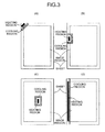
- FIG. 3(A) illustrates a heating region and a cooling region in a case where a corner portion of a sheet bundle is bound.
- the cooling region is provided at one portion at the lower right of the heating region in FIG. 3(A) as the position for reducing the heat transmission from the heating region to the image region.
- the image region can be overlaid on the cooling region, but it is impossible to arrange the image region close to the heating region beyond the cooling region because this may cause blocking.
- FIG. 3(B) illustrating the heating region and the cooling region in a case where a part of a side of the sheet bundle is bound
- the cooling region is also provided in the vertical direction because the image region exists in the vertical direction of the heating region in FIG. 3(B) , which is a difference from FIG. 3(A)
- the image region exists in all the directions, i.e., the upper, lower, right, and left directions, of the heating region, and therefore, the cooling region is also provided to enclose all the directions of the heating region.
- the cooling region can be changed in accordance with the mode of the heating region.
- the cooling region can also be provided in parallel to the heating region extending along the width direction at one end side in the conveying direction of the sheet bundle.
- FIG. 1 illustrates a cross section of the binding apparatus taken along the longitudinal direction of the sheet in FIG. 3(B)
- FIG. 2 illustrates a cross section of the binding apparatus taken along the width direction of the sheet in FIG. 3(B) .
- a Peltier device 9 is used instead of the heating/pressurizing member 2A using the heater as illustrated in FIG. 2 .
- the Peltier device 9 is provided to move the heat in the vertical direction in FIG. 4 , and electric current control is performed so that an upper end portion that is in contact with the support member 6 serves as a heat-absorbing end (heat-absorbing side), and a lower end portion where the surface member 7 is located serves as a heat radiation end (heat radiation side).
- the support member 6 is integrated with the pressurizing/cooling member 3.
- the Peltier device 9 when the Peltier device 9 is activated, the heat of the support member 6 and the pressurizing/cooling member 3 is moved through the heat radiation end of the Peltier device 9 to the location where the heating/pressurizing member 2A indicated by reference symbol 2A in FIG. 1 is located, i.e., to the surface member 7, at the heating/pressurizing member 2A, indicated by reference symbol 2A in FIG. 1 . Accordingly, the pressurizing/cooling member 3 is cooled, and the surface member 7 in contact with the sheet S at the heating/pressurizing member 2A is heated.
- a heat insulating material or a gap needs to be arranged between the pressurizing/cooling member and the Peltier device.
- the heat can be circulated with lower power consumption compared with the heater, and the high temperature of the heating/pressurizing member (the arrangement position indicated by reference symbol 2A in FIG. 1 ) can be maintained. As a result, the work time required to perform the binding processing can be reduced.
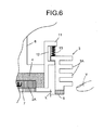
- pressurizing/cooling members 3 are provided in such a manner that the pressurizing/cooling members 3 can ascend/descend independently from an ascending/descending unit of the heating/pressurizing member 2A. Further, the pressurizing/cooling member 3 not only performs the independent ascending/descending operation but also configured such that a stroke by which the pressurizing/cooling member 3 moves away from the sheet S is less than a stroke by which the heating/pressurizing member 2A moves away from the sheet S (the size difference indicated by reference symbol L in FIG. 6 ).
- FIG. 5 is a figure illustrating a modification from the configuration as illustrated in FIG. 2 .
- an ascending/descending member 10 is provided at a position where the support member 6 and the pressurizing/cooling member 3 face each other.
- the ascending/descending member 10 ascends and descends the pressurizing/cooling member 3 independently from the support member 6.
- the ascending/descending member 10 uses a guide member for ascending/descending the pressurizing/cooling member 3 independently from the eccentric cam 5A, the elastic member 5B, and the support member 6 used in the ascending/descending mechanism 5 as illustrated in FIG. 2 .
- the cam profile of the eccentric cam 5A as illustrated in FIG. 5 is formed to satisfy the following condition.
- the condition is such that when the pressurizing/cooling member 3 moves away from the sheet S, the distance from the sheet surface is less than that of the heating/pressurizing member 2A, and in other words, a stroke that causes the pressurizing/cooling member 3 to be closer to the surface of the sheet S can be obtained.
- the pressurizing/cooling member 3 blocks entry of a finger Y when the finger Y enters into the heating/pressurizing member 2A from the outside.
- FIG. 6 is a figure illustrating another example of an ascending/descending mechanism for providing a dimension difference L explained above.
- the ascending/descending mechanism 5 includes an ascending/descending rail 12 provided at a portion in the guide member 11 fixed to the support member 6.
- the ascending/descending rail 12 is engaged with a portion of the pressurizing/cooling member 3.
- an elastic body 13 is arranged to urge the pressurizing/cooling member 3 toward the sheet S at all times.
- the upper surface of the pressurizing/cooling member 3 faces and is in contact with an eccentric cam (not illustrated) which is like the case as illustrated in FIG. 2 .
- the cam profile of the eccentric cam 5B is configured to satisfy, as the condition, the relationship, i.e., the stroke by which the heating/pressurizing member 2A moves away from the sheet S is less than the stroke by which the pressurizing/cooling member 3 moves away from the sheet S.
- the pressurizing/cooling member 3 can ascend/descend independently from the ascending/descending mechanism of the heating/pressurizing member 2A. Accordingly, like the case as illustrated in FIG. 5 explained above, the pressurizing/cooling member 3 blocks entry of the finger when the finger or the like enters toward the heating/pressurizing member 2A.
- this can increase the time in which the pressurizing/cooling member 3 is in contact with the sheet S. Accordingly, the cooling period for the sheet S can be longer than the heating period by the heating/pressurizing member 2A. As a result, the cooling around the region of the bonding toner on the sheet S can be done effectively.
- the cooling action around the bonding toner can be done effectively, and therefore, the heat transmission to the region of the normal image can be shielded, and the blocking phenomenon of the normal image can be suppressed effectively.
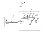
- the sheet post-processing apparatus 100 is arranged subsequently to an image forming apparatus 200 having a fixing device 210 which is a discharge unit of a sheet S.
- the image forming apparatus 200 has a configuration using well-known electrophotographic method.
- the image forming apparatus 200 includes photosensitive drums 201Y, 201M, 201C, 201K capable of forming toner images of Y, M, C, K, and the photosensitive drums 201Y, 201M, 201C, 201K transfer the toner images held thereon onto an intermediate transfer belt 202.
- the toner images transferred onto the intermediate transfer belt 202 in an overlapping manner are collectively transferred using the transfer roller 204.
- the fixing device 210 fixes the images on the sheet S onto which the toner images are collectively transferred, and the sheet S is discharged.
- the sheets S discharged from the fixing device 210 are successively stacked on the stacker illustrated in FIG. 1 , and thereafter, the bonding toner heated by the heating mechanism 2 is fused, and the sheets are pasted.
- the image forming system used in the present embodiment includes a combination of an image forming apparatus 301 and a binding processing apparatus 350 like the configuration as illustrated in FIG. 7 .
- the image forming apparatus 301 supports single-color image forming. Therefore, a single photosensitive drum is used, unlike the image forming system as illustrated in FIG. 7 .
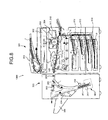
- a main body of the image forming apparatus 301 is provided with a document reading unit 302, an exposure unit 303, an image-forming unit 304, and a transfer unit 307.
- the document reading unit 302 is used to read image information of a document D which is set on the document conveying unit 310.
- the exposure unit 303 is used to emit exposure light L onto the photosensitive drum 305 to form an electrostatic latent image on the photosensitive drum 305 in accordance with the image information that is read by the document reading unit 302.
- a sheet P is fed selectively from multiple sheet feeding cassettes 312 to 314 to the transfer unit 307.
- the sheet P fed by the sheet feeding cassette is conveyed to the transfer unit 307 while a registration timing is controlled by a pair of registration rollers 317, 318 arranged in a conveying path K extended to the transfer unit 307.
- the sheet P onto which the toner image is transferred from the photosensitive drum 310 by the transfer unit 307 receives heating/pressurizing effect given by the fixing device 320 having the fixing roller 321 and the pressurizing roller 322, and the toner image is fixed on the sheet P.
- the sheet P on which the toner image is fixed is cooled by the cooling apparatus 325, and thereafter, the sheet P is discharged from the main body of the image forming apparatus 301.
- the sheet P discharged from the main body of the image forming apparatus 301 is introduced into the binding processing apparatus 350.
- the binding processing apparatus 350 is provided with a switching claw 352 capable of selecting any one from a conveying path toward the discharge unit 358 and a conveying path toward the binding processing unit 360 for performing the binding processing on the sheet P introduced.
- the switching claw 352 can switch a conveying direction of the sheet in accordance with a conveying mode of the sheet P selected with an operation panel (not illustrated) provided on the image forming apparatus 301. Any one of "normal discharge mode” and “binding processing mode” can be selected as a conveying mode. When a normal discharge mode is selected, the switching claw 352 is directed in such a direction that the sheet P discharged from the image forming apparatus 301 can pass a straight line conveying path 355, and can be conveyed to the discharge unit 358.
- the switching claw 352 When a binding processing mode is selected, the switching claw 352 is directed in such a direction that the sheet P discharged from the image forming apparatus 301 can pass a processing conveying path 353, and can be conveyed to the stacking unit 361.
- the binding processing unit 360 performs binding processing work.
- the sheet bundle PT having been subjected to the binding processing by the binding processing unit 360 is conveyed to the discharge unit 358 by the conveying roller 356 and the conveying belt 354.
- the binding processing unit 360 can select one of two cases: performing binding processing by performing heating/pressurizing operation on a plurality of sheets P at one time after the plurality of sheets P are stacked; and performing binding processing by performing the heating/pressurizing operation every time one sheet P is stacked.
- FIG. 9 is a figure illustrating a configuration of an essential portion of the binding processing apparatus 350.
- the binding unit 360 of the binding processing apparatus 350 is provided with a stacking unit 361 (stacking tray) on which multiple sheets P on which toner is fixed at a region, i.e., a binding margin portion A (in FIG. 9 , a heating range enclosed by a broken line) are stacked as a sheet bundle PT.
- a stacking unit 361 stacking tray on which multiple sheets P on which toner is fixed at a region, i.e., a binding margin portion A (in FIG. 9 , a heating range enclosed by a broken line) are stacked as a sheet bundle PT.
- each of the sheets P is stacked on the stacking unit 361 in such a state that a leading end portion is in abutment with an abutment portion 361a.
- the leading end portion of the sheet P stacked on the stacking unit 361 is a portion corresponding to the binding margin portion A, and is a portion for fixing the toner T for bonding the sheets P with each other, which is provided separately from the normal toner image.
- the bonding toner T is formed by being subjected to the image-forming step with the image-forming unit 304 and the fixing step with the fixing device 320 in the image forming apparatus main body 1.
- the toner image such as bonding is formed on leading end portions of surfaces of the second and subsequent sheets P of the multiple sheets P to be collected as the sheet bundle PT except the sheet P that is stacked first on the stacking unit 361.
- the bonding toner image uses a toner image made of a solid image in a belt shape along the width direction corresponding to the direction perpendicular to the surface of FIG. 9 .
- the binding unit 360 as illustrated in FIG. 9 includes not only a heating mechanism but also a cooling unit for cooling a sheet so that the heat of the binding margin portion does not diffuse to another portion of the sheet.
- the pressurizing units 363 to 369 and heating units 372, 373 are used.
- heat sinks 364, 365 are used.
- the toner T in the binding margin portion of the sheet bundle PT is melted through heating/pressurizing process by the heating units 372, 372 and the pressurizing units 362 to 369, whereby the sheets are pasted to each other in an adhesion state.
- Members included in the pressurizing units 362 to 369 include a receiving unit 362, a pressurizing unit 363, a guide rail 367, a movable plate 368, an eccentric cam 366, and a tension spring 369.
- the difference of the configuration as illustrated in FIG. 9 from the embodiment illustrated in FIG. 1 lies in a lower portion pressurizing/cooling member (in FIG. 1 , a member indicated by reference symbol 3') provided on a lower surface of a sheet (in FIG. 1 , a member indicated by reference symbol S) in a binding mechanism as illustrated in FIG. 1 .
- the heat sink 364 is integrated adjacent to a heating ceramic heater 372 provided on a receiving unit 362 which is a fixing unit facing the back side of the sheet P corresponding to the opposite side to the carrying surface of the toner T.
- FIG. 10 is an enlarged view of a receiving unit 362 and a pressurizing unit 363.
- the receiving unit 362, the pressurizing unit 363, and the heat sinks 364, 365 are provided with surface layers 362a, 363a, 364a, 365a, respectively.
- each surface layer is provided with a first layer for preventing the sheet P and the toner T from sticking thereto and a second layer for achieving uniform pressurizing process.
- the first layer is made of a material having low surface energy such as fluorine resin and silicone resin
- the second layer is made of silicone rubber and fluoro-rubber serving as a cushion layer.
- the heating units 372, 372 may be made of a resistance heating body, a halogen heater, or an electromagnetic induction coil instead of the heating ceramic heater 372, and even when such member is used, the heating temperature is determined to be equal to or more than a melting point of the toner T.
- the receiving unit 262 and the pressurizing unit 363 are provided with heat insulating layers 362b, 363b serving as insulating members between the heat sinks 364, 365 (cooling unit) and the ceramic heaters 372, 373 (heating unit). More specifically, as illustrated in FIG. 10 , the receiving unit 362 and the pressurizing unit 363 are provided with the heat insulating layers 362b, 363b (insulating member) so as to cover the portion except the surface layers 362a, 363a.
- this can eliminate the defect of decrease in the cooling efficiency of the heat sinks 364, 365 by the heating of the ceramic heaters 372, 373 and the defect of decrease in the heating efficiency of the ceramic heaters 372, 373 by the cooling of the heat sinks 364, 365.
- the temperature of the image portion of the sheet P does not increase abnormally, and the blocking phenomenon, i.e., phenomenon in which the overlapping sheets are bonded with each other due to the increase of the adhesiveness of the toner, can be alleviated.
- the binding processing apparatus 350 as illustrated in FIG. 11 is used to bond substantially the entire surfaces of two sheets P1, P2 facing each other.
- the different types correspond to a combination such that the first sheet P1 is a transparent sheet, and the second sheet is an opaque sheet.
- the binding processing apparatus can bond both of the sheets P1, P2 by using, as the bonding agent, all the toner images interposed between the first sheet P1 and the second sheet P2.
- FIG. 11 illustrates a state that the two sheets P1, P2 are stacked on the stacking unit 361 in such a state that the pressurizing roller 392 is kept away from the heating roller 391.
- the heating roller 391 including the heater and the pressurizing roller 392 are brought into contact with the sheets P1, P2, and the abutment portion 361a is moved in a black arrow direction, whereby the two sheets P1, P2 are conveyed to the nip portion of both of the rollers 391, 392.
- the conveying belt 354 is provided with a cooling apparatus 95 for fixing the toner that is melted/fused by the nip portion.
- the toner is solidified while passing the conveying belt 354, and the sheets P1, P2 thus bonded to each other pass past the conveying belt 354, and thereafter, the sheets P1, P2 are discharged to the outside of the apparatus 350.
- the sheet fixed by the fixing device 320 as illustrated in FIG. 8 is provided to the pressurizing/heating processing while the sheet is not cooled by the cooling apparatus 325.
- the sheet that is not cooled after the fixing step alleviates the decrease in the temperature of the toner T used for bonding the sheets with each other, and this corresponds to a pre-heating step for the pressurizing/heating operation used for the bonding work of the sheets with each other.
- the fixing device 320 is configured to adjust the quantity of heat given to the sheet.
- the heat remaining in the sheet having been subjected to the fixing process is treated as pre-heating in the pressurizing/heating process during the binding processing, whereby the bonding performance can be enhanced by increasing the melting efficiency of the toner used as bonding agent in accordance with the thickness of the sheet.
- the binding processing apparatus there may be, on the opposing surfaces of the two sheets P1, P2 bonded to each other, a portion where strong bonding state of the toners used as the bonding agent is preferably avoided. More specifically, a very high quantity of heat is given to the binding portion bonded by melting the toner, and therefore, the toner image located in proximity thereto is also likely to be affected by the heat. For this reason, a portion of the toner image may be strongly crushed.
- a portion of a toner image portion in proximity to the binding portion which is likely to be affected by the heat by the binding portion is cooled on the stacking unit 361, before the sheets P1, P2 pass the nip portion of the rollers 391, 392 used for the pressurizing/heating processing.
- the configuration of the cooling unit of the present embodiment can be applied.
- Combinations of two different sheets P1, P2 include not only what has been described above but also various combinations including a combination of a Lenticular sheet and a sheet serving as a basis and a combination of a colored sheet serving as a basis and a transparent sheet formed with an image made by reversing the vertical and horizontal direction on the back surface side of the sheet.
- an image-forming unit 304 for forming an image with a colored toner can be installed in the image forming apparatus main body 1.
- a transparent toner not affecting colored toner image is used as the bonding agent, and therefore, regardless of the size of the colored toner image and the position, the size and the position of the binding portion can be determined. As a result, the size and the binding position number of binding portions can be appropriately obtained in order to obtain the strength required for bonding.
- the present invention can be applied to the binding processing apparatus 350 installed in the image forming apparatus 301 according to the electrophotographic method, but the application of the present invention is not limited thereto.
- the present invention can be naturally applied to a binding apparatus installed in an image forming apparatus according to other methods (for example, an image forming apparatus of ink jet method).
- the present invention can be applied to a binding apparatus formed as a single apparatus (for example, a sheet feeding cassette is set in a conveying port, and an operation panel for inputting processing mode and/or the like is installed in the binding processing apparatus itself). Even in such case, the same effects as the present embodiment can be obtained.
- a cooling unit cools a sheet so that the heat of the binding margin portion does not diffuse to another portion of the sheet. Accordingly, a binding apparatus and an image forming apparatus can be provided, in which the heat does not diffuse to a portion other than the binding margin portion in the sheet and the blocking phenomenon does not occur even when toner is used to perform the binding processing.
Landscapes
- Physics & Mathematics (AREA)
- General Physics & Mathematics (AREA)
- Folding Of Thin Sheet-Like Materials, Special Discharging Devices, And Others (AREA)
- Paper Feeding For Electrophotography (AREA)
Abstract
Description
- The present application claims priority to and incorporates by reference the entire contents of Japanese Patent Application No.
2013-027006 2013-049872 2013-228007 - The present invention relates to a binding processing apparatus and an image forming system, and more particularly, to a binding processing mechanism performed on an image-formed sheet.
- Sheets printed by an image forming apparatus such as a copier, a printer, or a printing machine may be, other than being discharged from the image forming apparatus, subjected to post-processing such as binding processing with a stapler while a predetermined number of sheets are made into a bundle. A binding processing apparatus joined with a sheet discharge unit of the image forming apparatus is used as an apparatus for this purpose.
- In general, the binding processing use staples, but in recent years, an apparatus that does not use metallic products such as staples is desired in view of the resource saving, ecology, and recycle performance.
- A configuration for attaching sheets with each other by heating and fusing toner used for image forming as adhesive agent has been suggested as one type of the apparatus explained above (for example,
Japanese Laid-open Patent Publication No. 2005-219849 2004-209859 - Japanese Laid-open Patent Publication No.
2005-219849 2004-209859 - On the other hand, a configuration for performing binding processing of sheets by heating and pressurizing a binding margin portion of sheets stacked on a stacking unit on a per-sheet basis is known as a configuration used for binding processing (for example, Japanese Laid-open Patent Publication No.
2000-255881 - In the method for performing binding processing by fusing a toner image used for image forming process, there is a problem in the handling of heat that is exerted on the fusing of the toner image.
- More specifically, when the heating and pressurizing of the toner image is performed only on the bonding portion, the heat exerted on the bonding portion is propagated to a portion other than the bonding portion.
- In particular, when the quantity of heat and the pressure during the heating and pressurizing process increase in proportion to the number of sheets subjected to the binding processing, the quantity of heat propagated to the periphery of the bonding portion increases.
- For this reason, the normal toner image formed in the periphery of the bonding portion is also affected by the heat. When the quantity of heat increases, the normal toner image is also melted again, and the adhesiveness of the toner increases. Due to such phenomenon, blocking phenomenon, such as the stacked sheets being likely to bond each other and the toner image being likely to be destroyed, occurs, and binding failure occurs and/or a defective image is obtained.
- In particular, sheets for which fixing work is performed on the normal toner image during image forming process are more likely to receive heat made by the heating and pressurizing process again when the sheets discharged from the image forming apparatus are subjected to the binding processing as they are. Accordingly, there is a risk that in the normal toner image, the heat during the bonding binding processing is applied to the normal toner image in addition to the remaining heat after fixing, so that the blocking phenomenon becomes significant.
- In particular, the configuration of Japanese Laid-open Patent Publication No.
2005-219849 - In view of the problem associated with the conventional sheet post-processing apparatus explained above, and more particularly, in view of the problem associated with the binding processing using the fusing of the toner image, there is a need to provide a sheet post-processing apparatus and an image forming system having a configuration of reliably preventing blocking phenomenon in a normal toner image.
- It is an object of the present invention to at least partially solve the problems in the conventional technology.
- A binding processing apparatus performs binding processing on a sheet bundle. The binding processing apparatus includes: a stacking unit configured to stack multiple sheets, as the sheet bundle, in a state where toner is fixed to a part or all of a region which becomes a binding margin portion; a pressurizing unit configured to sandwich and pressurize the binding margin portion; a heating unit configured to heat the toner in the binding margin portion in a state where the binding margin portion is pressurized by the pressurizing unit; and a cooling unit configured to cool the sheets so that the heat of the binding margin portion does not diffuse to another portion of the sheets when the heating unit heats the binding margin portion.
- A binding processing apparatus is capable of bonding sheets with each other to bind the sheets by melting a bonding toner using a heating mechanism having a heating/pressurizing member capable of ascending/descending with respect to the sheets carrying the bonding toner. A pressurizing/cooling member capable of ascending/descending together with the heating/pressurizing member is provided in proximity to a binding margin portion and in proximity to the heating/pressurizing member. The pressurizing/cooling member can come into contact with or move away from a proximity of the bonding toner carried on the sheets in synchronization with ascending/descending operation of the heating/pressurizing member.
- The above and other objects, features, advantages and technical and industrial significance of this invention will be better understood by reading the following detailed description of presently preferred embodiments of the invention, when considered in connection with the accompanying drawings.
-
-
FIG. 1 is a schematic figure for explaining a schematic configuration of a sheet post-processing apparatus according to an embodiment of the present invention; -
FIG. 2 is a schematic figure for explaining an example of a heating/pressurizing member and a pressurizing/cooling member used for the sheet post-processing apparatus according to the embodiment of the present invention; -
FIG. 3 is a figure for explaining action in a case where the heating/pressurizing member and the pressurizing/cooling member as illustrated inFIG. 2 are used; -
FIG. 4 is a schematic diagram corresponding toFIG. 2 for explaining a modification about a configuration of the heating/pressurizing member and the pressurizing/cooling member as illustrated inFIG. 2 ; -
FIG. 5 is a schematic diagram corresponding toFIG. 2 for explaining a modification of an essential portion about a configuration of the heating/pressurizing member and the pressurizing/cooling member as illustrated inFIG. 2 ; -
FIG. 6 is a schematic diagram corresponding toFIG. 2 for explaining a still another modification of an essential portion about a configuration of the heating/pressurizing member and the pressurizing/cooling member as illustrated inFIG. 2 ; -
FIG. 7 is a schematic figure for explaining an image forming system using a sheet post-processing apparatus according to an embodiment of the present invention; -
FIG. 8 is a schematic diagram for explaining an image forming system including an image forming apparatus using a binding processing apparatus according to another embodiment of the present invention; -
FIG. 9 is a figure for explaining an essential configuration of a binding processing apparatus used in the image forming apparatus as illustrated inFIG. 8 ; -
FIG. 10 is a schematic diagram for explaining a configuration of a binding unit of the binding processing apparatus as illustrated inFIG. 9 ; and -
FIG. 11 is a figure for explaining a modification of an essential portion of the configuration as illustrated inFIG. 9 . - Hereinafter, a mode for carrying out the present invention will be explained with reference to an embodiment illustrated with drawings.
-
FIG. 1 is a figure for explaining a configuration serving as a principle of a sheet post-processing apparatus according to an embodiment of the present invention. - In
FIG. 1 , asheet post-processing apparatus 100 includes a stacker 1 capable of stacking sheets S discharged from a sheet discharge unit of afixing device 210 of animage forming apparatus 200 as illustrated inFIG. 7 . - The stacker 1 is provided with an
abutment guide 1A for aligning an end edge of a sheet S at a position facing a leading end edge of the sheet S in a discharge direction of the sheet S. - In proximity to the
abutment guide 1A, aheating mechanism 2 corresponding to the binding position of the sheet S is provided. - The
heating mechanism 2 has a heating/pressurizingmember 2A that can ascend and descend with respect to the sheet S. The heating/pressurizingmember 2A can heat the sheet S in the process of pressurizing the sheet S while being in contact with the sheet S. When bonding toner carried by the sheet S is melted, the sheets are bonded to each other to be bound. - A feature of the present embodiment based on the above configuration will be explained as follows.
- The feature of the present embodiment lies in that a cooling unit is provided to cool a sheet so that the heat of a binding margin portion does not diffuse to another portion of the sheet when the binding margin portion corresponding to the binding position is heated with a heating unit corresponding to the
heating mechanism 2. - More specifically, in proximity to the heating/pressurizing
member 2A of theheating mechanism 2, a pressurizing/cooling member 3 is provided, which serves as a cooling unit capable of ascending and descending in synchronization with ascend and descend operation of the heating/pressurizingmember 2A together with the heating/pressurizingmember 2A. - The pressurizing/
cooling member 3 is a member that is arranged at a position adjacent to the heating/pressurizingmember 2A and that can come into contact with and move away from the sheet S. The pressurizing/cooling member 3 can pressurize the sheet S around the heating/pressurizingmember 2A in synchronization with operation in which the heating/pressurizingmember 2A pressurizes the sheet. - The pressurizing/
cooling member 3 is used to cool the periphery of the bonding toner while pressurizing the peripheral portion of the bonding toner in the sheet S in synchronization with the time with which the heating/pressurizingmember 2A comes into contact with the sheet S. - By setting the operation time of the pressurizing/
cooling member 3, the pressurizing/cooling member 3 does not come into contact with the sheet S and cool the sheet S before the heating/pressurizingmember 2A starts the heating and pressurizing process. Accordingly, this can prevent such phenomenon that the temperature rise is affected due to the cooling effect when the pressurizing/cooling member 3 comes into contact before the heating/pressurizingmember 2A comes into contact with the sheet S. - The surface temperature of the pressurizing/
cooling member 3 is configured to be a temperature at which cooling can be done at a temperature lower than the surface temperature of the sheet S discharged from thefixing device 210 before the contact. More specifically, the surface temperature of the sheet S discharged from thefixing device 210 is configured to be a surface temperature equal to or less than 60 degrees Celsius in a case where the sheet S is discharged at a temperature of about 60 degrees Celsius in contrast to 70 degrees Celsius which is the temperature at which blocking phenomenon occurs in a normal image. - In the above configuration, the sheets S discharged from the
fixing device 210 are stacked on the stacker 1, and when a predetermined number of sheets S are stacked, theheating mechanism 2 performs the binding processing. - The binding processing is done by heating the sheet S while pressurizing the sheet S by the heating/pressurizing
member 2A of theheating mechanism 2. - On the sheet S, the bonding toner image is formed in advance at the binding position, the sheets are bonded to each other making use of adhesive property of the toner when the toner is melted, by heating the bonding toner image to a temperature equal to or more than a toner melting/fusion temperature while the heating/pressurizing
member 2A pressurizing the sheet S onto the bonding toner image. - On the other hand, as the heating/pressurizing
member 2A descends and pressurizes the sheet S, the pressurizing/coolingmember 3 pressurizes the periphery of the bonding toner in the sheet S. - When the pressurizing/cooling
member 3 pressurizes the sheet S, this suppresses the transmission of the heat given by the heating/pressurizingmember 2A, to the peripheral portion from the bonding toner. - Therefore, in the sheet S, the heat which is transmitted from the bonding toner region to the region of the normal toner image (which may be hereinafter also referred to as normal image for the sake of convenience) is absorbed by the pressurizing/cooling
member 3, and therefore, in the normal image, rise of the temperature is suppressed, and the blocking phenomenon is prevented. - In particular, the surface temperature of the pressurizing/cooling
member 3 can be set to a temperature equal to or less than the surface temperature of the sheet S when the sheet S is discharged from the fixing device 210 (seeFIG. 7 ). Accordingly, the temperature in the peripheral portion around the bonding toner has margin against the temperature at which the blocking phenomenon occurs. As a result, this maintains the state that the heat is hardly transmitted to the normal image on the sheet S, and therefore, the blocking phenomenon hardly occurs in the normal image. - In the configuration as illustrated in
FIG. 1 , theheating mechanisms 2 are provided not only on the upper surface side but also the lower surface side of the sheet S. Further, a lower portion pressurizing/cooling member 3' adjacent to a heating/pressurizing member (inFIG. 1 , a member indicated byreference symbol 2A') on the lower surface side is provided. - With regard to the surface temperature, the lower portion pressurizing/cooling member 3' is set to the same condition as the pressurizing/cooling
member 3 located at the upper surface side of the sheet S. - In this configuration, the heating efficiency can be improved when the binding processing is performed on a sheet bundle including a relatively small number of sheets. As a result, the binding processing from both sides, i.e., the front side and the back side, can be done on the sheet bundle in a shorter time.
- When the lower portion pressurizing/cooling apparatus 3' is configured not to ascend and descend and be in contact with the lower surface of the sheet S at all times, the cooling effect would be improved as compared with a case where it comes into contact therewith and moves away therefrom. In this case, in view of the heat loss that occurs when the heating/pressurizing
member 2A is used, the heating temperature is set to a higher temperature as compared with the one located on the upper surface side of the sheet S. It should be noted that the lower portion pressurizing/cooling member 3' can also be configured to ascend and descend just like the one located on the upper surface of the sheet S. - In the above configuration, the pressurizing/cooling
member 3 which is in contact with the sheet S suppresses the heat transmitted from the pasting region using the bonding toner on the surface of the sheet S to the region where the normal toner image exists, and therefore, it is not necessary to do any heat insulating processing on the sheet S. - More specifically, it is conceivable to provide a heat insulating portion such as holes, which interpose air layer in proximity to the region where the bonding toner is formed, as a configuration for suppressing the heat transmission in the sheet S. However, when holes or the like are made in a portion of the sheet, the tensile strength may be reduced in that portion, and the sheet is likely to be torn apart by the pulling force that is generated when the sheet S is turned.
- In contrast, in the configuration as illustrated in
FIG. 1 , processing such as holes in the sheet S is not required, and therefore, the blocking phenomenon can be prevented by suppressing the heat transmission to the normal image without impairing the tensile strength of the sheet S. - Specific configuration of the heating/pressurizing
member 2A used in theheating mechanism 2 and the pressurizing/coolingmember 3 adjacent thereto as illustrated inFIG. 1 will be hereinafter explained. -
FIG. 2 is a figure illustrating a configuration of the heating/pressurizingmember 2A and pressurizing/coolingmember 3 used in theheating mechanism 2. InFIG. 2 , theheating mechanism 2 is configured such that the heating/pressurizingmember 2A having the heater therein is supported by asupport member 6 driven by an ascending/descending mechanism 5 with theheat insulating material 4 interposed therebetween. - The ascending/
descending mechanism 5 has anelastic body 5B urging thesupport member 6 in contact with theeccentric cam 5A toward the sheet S at all times. - The heating/pressurizing
member 2A is integrated with thesurface member 7 on its side toward a contact surface with the sheet S. - The
surface member 7 is used to achieve the following functions. First, thesurface member 7 is used to prevent the sheet S and the toner from sticking thereto, and secondly, to cause the outermost layer and the sheet to be uniformly in contact with each other. - A material having low surface energy such as fluorine resin and silicone resin is used as the first layer for achieving the first function. Silicone rubber and fluoro-rubber serving as a cushion layer are used as the second layer achieving the second function.
- Such surface member is also provided for the pressurizing/cooling
member 3 which is a member in contact with the sheet S like the heating/pressurizingmember 2A (inFIG. 2 , the surface member for the pressurizing/coolingmember 3 is indicated by reference symbol 8). - On the other hand, the pressurizing/cooling
member 3 uses a structure capable of maintaining the temperature at a low level, and in the configuration as illustrated inFIG. 2 , a heat sink havingmultiple radiation fins 3A is used. The pressurizing/coolingmember 3 uses the configuration capable of achieving heat radiation effect like a heat sink. More specifically, a configuration capable of transmitting the heat to a chassis, not illustrated, via thesupport member 6 and the ascending/descending mechanism 5 is desired, and a configuration for cooling with the heat radiation from the chassis is used. Not only the use of heat transmission but also a member for forcibly cooling using a heat pump such as a Peltier device may also be used. - In order to effectively achieve the heat radiation by the pressurizing/cooling
member 3, blocking the heat transmission from the heating/pressurizingmember 2A to prioritize the direct contact relationship between the sheet and the pressurizing/coolingmember 3 is important for efficiently radiating the heat from the sheet. Therefore, in this configuration, it is preferable that a heat insulating layer such as air layer is preferably interposed between both of the members, which is not illustrated, or theheat insulating material 4 as illustrated inFIG. 2 is used. - The ascending/
descending mechanism 5 as illustrated inFIG. 2 is a configuration used for ascending/descending the heating/pressurizingmember 2A and the pressurizing/coolingmember 3 at a time. - The ascending/
descending mechanism 5 uses theeccentric cam 5A which is in contact with thesupport member 6 that ascends/descends both of the members at a time. Instead of the configuration using theeccentric cam 5A and the motor which is the driving source, the configuration including a combination of the motor and a reduction mechanism may be used, or a linear actuator using electromagnetism, hydraulics, or air pressure may be used. - On the other hand, the way to provide the minimum required cooling region depends on the relationship of the binding position with respect to the image region where the normal toner image exists.
- The relationship between the sheet binding position /binding position and the cooling region will be explained with reference to
FIGS. 3(A) to 3(D) . -
FIG. 3(A) illustrates a heating region and a cooling region in a case where a corner portion of a sheet bundle is bound. The cooling region is provided at one portion at the lower right of the heating region inFIG. 3(A) as the position for reducing the heat transmission from the heating region to the image region. - The image region can be overlaid on the cooling region, but it is impossible to arrange the image region close to the heating region beyond the cooling region because this may cause blocking.
- In
FIG. 3(B) illustrating the heating region and the cooling region in a case where a part of a side of the sheet bundle is bound, the cooling region is also provided in the vertical direction because the image region exists in the vertical direction of the heating region inFIG. 3(B) , which is a difference fromFIG. 3(A) - In
FIG. 3(C) illustrating the heating region and the cooling region in a case where the intermediate portion of the sheet bundle is bound, the image region exists in all the directions, i.e., the upper, lower, right, and left directions, of the heating region, and therefore, the cooling region is also provided to enclose all the directions of the heating region. - It should be noted that the cooling region can be changed in accordance with the mode of the heating region. For example, as illustrated in
FIG. 3(D) , the cooling region can also be provided in parallel to the heating region extending along the width direction at one end side in the conveying direction of the sheet bundle. - In
FIG. 1 , the pressurizing/coolingmember 3 is drawn only at one portion at the right of the heating/pressurizingmember 2A, and in contrast, inFIG. 2 , the pressurizing/coolingmember 3 is drawn at both sides of the pressurizing/heating member 2A. However, this is becauseFIG. 1 illustrates a cross section of the binding apparatus taken along the longitudinal direction of the sheet inFIG. 3(B) , andFIG. 2 illustrates a cross section of the binding apparatus taken along the width direction of the sheet inFIG. 3(B) . - Subsequently, another example of a pressurizing/cooling
member 3 will be explained. - In the configuration as illustrated in
FIG. 4 , a Peltier device 9 is used instead of the heating/pressurizingmember 2A using the heater as illustrated inFIG. 2 . - The Peltier device 9 is provided to move the heat in the vertical direction in
FIG. 4 , and electric current control is performed so that an upper end portion that is in contact with thesupport member 6 serves as a heat-absorbing end (heat-absorbing side), and a lower end portion where thesurface member 7 is located serves as a heat radiation end (heat radiation side). - Like the case as illustrated in
FIG. 2 , thesupport member 6 is integrated with the pressurizing/coolingmember 3. - In the above configuration, when the Peltier device 9 is activated, the heat of the
support member 6 and the pressurizing/coolingmember 3 is moved through the heat radiation end of the Peltier device 9 to the location where the heating/pressurizingmember 2A indicated byreference symbol 2A inFIG. 1 is located, i.e., to thesurface member 7, at the heating/pressurizingmember 2A, indicated byreference symbol 2A inFIG. 1 . Accordingly, the pressurizing/coolingmember 3 is cooled, and thesurface member 7 in contact with the sheet S at the heating/pressurizingmember 2A is heated. - At the side surface of the Peltier device, not only the heat-absorbing end but also the heat radiation end appear, and therefore, a heat insulating material or a gap needs to be arranged between the pressurizing/cooling member and the Peltier device.
- In the configuration as illustrated in
FIG. 4 , when the heat is absorbed at the pressurizing/coolingmember 3 by the Peltier device 9 capable of setting the heat-absorbing end and the heat radiation end, the heat is transmitted to the heat radiation side of the Peltier device 9, i.e., to the side where the heating/pressurizingmember 2A is provided inFIG. 1 . As a result, the heat is transmitted to the sheet S at the side where the pressurizing/heating member is provided, and the bonding toner carried on the sheet S is melted. - In this configuration, the heat can be circulated with lower power consumption compared with the heater, and the high temperature of the heating/pressurizing member (the arrangement position indicated by
reference symbol 2A inFIG. 1 ) can be maintained. As a result, the work time required to perform the binding processing can be reduced. - Subsequently, a modification of a configuration used in the binding processing apparatus according to the embodiment of the present invention will be explained.
- In the configuration as illustrated in
FIGS. 5 and6 , pressurizing/cooling members 3 are provided in such a manner that the pressurizing/cooling members 3 can ascend/descend independently from an ascending/descending unit of the heating/pressurizingmember 2A. Further, the pressurizing/coolingmember 3 not only performs the independent ascending/descending operation but also configured such that a stroke by which the pressurizing/coolingmember 3 moves away from the sheet S is less than a stroke by which the heating/pressurizingmember 2A moves away from the sheet S (the size difference indicated by reference symbol L inFIG. 6 ). - Hereinafter, this configuration will be explained.
-
FIG. 5 is a figure illustrating a modification from the configuration as illustrated inFIG. 2 . - In
FIG. 5 , at a position where thesupport member 6 and the pressurizing/coolingmember 3 face each other, an ascending/descendingmember 10 is provided. The ascending/descendingmember 10 ascends and descends the pressurizing/coolingmember 3 independently from thesupport member 6. - The ascending/descending
member 10 uses a guide member for ascending/descending the pressurizing/coolingmember 3 independently from theeccentric cam 5A, theelastic member 5B, and thesupport member 6 used in the ascending/descending mechanism 5 as illustrated inFIG. 2 . - The cam profile of the
eccentric cam 5A as illustrated inFIG. 5 is formed to satisfy the following condition. - The condition is such that when the pressurizing/cooling
member 3 moves away from the sheet S, the distance from the sheet surface is less than that of the heating/pressurizingmember 2A, and in other words, a stroke that causes the pressurizing/coolingmember 3 to be closer to the surface of the sheet S can be obtained. - Accordingly, when the pressurizing/cooling
member 3 rises to move away from the sheet S, the distance of the heating/pressurizingmember 2A from the surface of the sheet S is farther than the distance of the pressurizing/coolingmember 3 from the surface of the sheet S. As a result, as indicated by reference symbol L inFIG. 6 , the pressurizing/coolingmember 3 blocks entry of a finger Y when the finger Y enters into the heating/pressurizingmember 2A from the outside. -
FIG. 6 is a figure illustrating another example of an ascending/descending mechanism for providing a dimension difference L explained above. - In
FIG. 6 , the ascending/descending mechanism 5 includes an ascending/descendingrail 12 provided at a portion in theguide member 11 fixed to thesupport member 6. The ascending/descendingrail 12 is engaged with a portion of the pressurizing/coolingmember 3. - In the
guide member 11 where the upper surface of the pressurizing/coolingmember 3 and the ascending/descendingrail 12 are located, anelastic body 13 is arranged to urge the pressurizing/coolingmember 3 toward the sheet S at all times. The upper surface of the pressurizing/coolingmember 3 faces and is in contact with an eccentric cam (not illustrated) which is like the case as illustrated inFIG. 2 . - Like the case explained in
FIG. 5 , in this case, the cam profile of theeccentric cam 5B is configured to satisfy, as the condition, the relationship, i.e., the stroke by which the heating/pressurizingmember 2A moves away from the sheet S is less than the stroke by which the pressurizing/coolingmember 3 moves away from the sheet S. - In the above configuration, the pressurizing/cooling
member 3 can ascend/descend independently from the ascending/descending mechanism of the heating/pressurizingmember 2A. Accordingly, like the case as illustrated inFIG. 5 explained above, the pressurizing/coolingmember 3 blocks entry of the finger when the finger or the like enters toward the heating/pressurizingmember 2A. - In addition, this can increase the time in which the pressurizing/cooling
member 3 is in contact with the sheet S. Accordingly, the cooling period for the sheet S can be longer than the heating period by the heating/pressurizingmember 2A. As a result, the cooling around the region of the bonding toner on the sheet S can be done effectively. - In such configuration, the cooling action around the bonding toner can be done effectively, and therefore, the heat transmission to the region of the normal image can be shielded, and the blocking phenomenon of the normal image can be suppressed effectively.
- Subsequently, an image forming system having a sheet
post-processing apparatus 100 configured as described above will be explained. - In an
image forming system 1000 ofFIG. 7 , the sheetpost-processing apparatus 100 is arranged subsequently to animage forming apparatus 200 having a fixingdevice 210 which is a discharge unit of a sheet S. - The
image forming apparatus 200 has a configuration using well-known electrophotographic method. - More specifically, the
image forming apparatus 200 includesphotosensitive drums photosensitive drums intermediate transfer belt 202. - While a registration timing with which the sheets S fed by a sheet feeding device, not illustrated, is set with a
registration roller 203, the toner images transferred onto theintermediate transfer belt 202 in an overlapping manner are collectively transferred using thetransfer roller 204. The fixingdevice 210 fixes the images on the sheet S onto which the toner images are collectively transferred, and the sheet S is discharged. - When a binding mode is selected with a control unit, not illustrated, the sheets S discharged from the fixing
device 210 are successively stacked on the stacker illustrated inFIG. 1 , and thereafter, the bonding toner heated by theheating mechanism 2 is fused, and the sheets are pasted. - Subsequently, an image forming system including an image forming apparatus to which a binding processing apparatus according to another embodiment of the present invention is applied will be explained.
- The image forming system used in the present embodiment includes a combination of an
image forming apparatus 301 and abinding processing apparatus 350 like the configuration as illustrated inFIG. 7 . - Unlike the configuration as illustrated in
FIG. 7 , theimage forming apparatus 301 supports single-color image forming. Therefore, a single photosensitive drum is used, unlike the image forming system as illustrated inFIG. 7 . - In
FIG. 8 , a main body of theimage forming apparatus 301 is provided with adocument reading unit 302, anexposure unit 303, an image-formingunit 304, and atransfer unit 307. - The
document reading unit 302 is used to read image information of a document D which is set on thedocument conveying unit 310. - The
exposure unit 303 is used to emit exposure light L onto thephotosensitive drum 305 to form an electrostatic latent image on thephotosensitive drum 305 in accordance with the image information that is read by thedocument reading unit 302. - A sheet P is fed selectively from multiple
sheet feeding cassettes 312 to 314 to thetransfer unit 307. - The sheet P fed by the sheet feeding cassette is conveyed to the
transfer unit 307 while a registration timing is controlled by a pair of registration rollers 317, 318 arranged in a conveying path K extended to thetransfer unit 307. - The sheet P onto which the toner image is transferred from the
photosensitive drum 310 by thetransfer unit 307 receives heating/pressurizing effect given by the fixingdevice 320 having the fixingroller 321 and the pressurizingroller 322, and the toner image is fixed on the sheet P. The sheet P on which the toner image is fixed is cooled by thecooling apparatus 325, and thereafter, the sheet P is discharged from the main body of theimage forming apparatus 301. - The sheet P discharged from the main body of the
image forming apparatus 301 is introduced into the bindingprocessing apparatus 350. - The binding
processing apparatus 350 is provided with a switchingclaw 352 capable of selecting any one from a conveying path toward thedischarge unit 358 and a conveying path toward the bindingprocessing unit 360 for performing the binding processing on the sheet P introduced. - The switching
claw 352 can switch a conveying direction of the sheet in accordance with a conveying mode of the sheet P selected with an operation panel (not illustrated) provided on theimage forming apparatus 301. Any one of "normal discharge mode" and "binding processing mode" can be selected as a conveying mode. When a normal discharge mode is selected, the switchingclaw 352 is directed in such a direction that the sheet P discharged from theimage forming apparatus 301 can pass a straightline conveying path 355, and can be conveyed to thedischarge unit 358. - When a binding processing mode is selected, the switching
claw 352 is directed in such a direction that the sheet P discharged from theimage forming apparatus 301 can pass a processing conveying path 353, and can be conveyed to the stackingunit 361. - When a predetermined number of sheets P are conveyed to the stacking
unit 361, the end edge of the sheet P in the width direction and the leading end of the sheet P in the conveying direction are aligned by a jogger fence (not illustrated), and thebinding processing unit 360 performs binding processing work. - The sheet bundle PT having been subjected to the binding processing by the binding
processing unit 360 is conveyed to thedischarge unit 358 by the conveyingroller 356 and the conveyingbelt 354. - After multiple sheets P are stacked, the binding
processing unit 360 can select one of two cases: performing binding processing by performing heating/pressurizing operation on a plurality of sheets P at one time after the plurality of sheets P are stacked; and performing binding processing by performing the heating/pressurizing operation every time one sheet P is stacked. -
FIG. 9 is a figure illustrating a configuration of an essential portion of thebinding processing apparatus 350. - In
FIG. 9 , the bindingunit 360 of thebinding processing apparatus 350 is provided with a stacking unit 361 (stacking tray) on which multiple sheets P on which toner is fixed at a region, i.e., a binding margin portion A (inFIG. 9 , a heating range enclosed by a broken line) are stacked as a sheet bundle PT. - After the sheet P on which the images are formed is subjected to an image-forming step with the image-forming
unit 304 and a fixing step with the fixingdevice 320 in the image forming apparatus main body 1 is conveyed to thebinding apparatus 350, each of the sheets P is stacked on the stackingunit 361 in such a state that a leading end portion is in abutment with anabutment portion 361a. - In this case, the leading end portion of the sheet P stacked on the stacking
unit 361 is a portion corresponding to the binding margin portion A, and is a portion for fixing the toner T for bonding the sheets P with each other, which is provided separately from the normal toner image. - Like to the normal toner image, the bonding toner T is formed by being subjected to the image-forming step with the image-forming
unit 304 and the fixing step with the fixingdevice 320 in the image forming apparatus main body 1. - In the present embodiment, the toner image such as bonding is formed on leading end portions of surfaces of the second and subsequent sheets P of the multiple sheets P to be collected as the sheet bundle PT except the sheet P that is stacked first on the stacking
unit 361. The bonding toner image uses a toner image made of a solid image in a belt shape along the width direction corresponding to the direction perpendicular to the surface ofFIG. 9 . - Like the embodiment as illustrated in
FIG. 1 , the bindingunit 360 as illustrated inFIG. 9 includes not only a heating mechanism but also a cooling unit for cooling a sheet so that the heat of the binding margin portion does not diffuse to another portion of the sheet. - In the heating mechanism of
FIG. 9 , the pressurizingunits 363 to 369 andheating units heat sinks - In the
binding unit 360, like the embodiment explained above, the toner T in the binding margin portion of the sheet bundle PT is melted through heating/pressurizing process by theheating units units 362 to 369, whereby the sheets are pasted to each other in an adhesion state. - Members included in the pressurizing
units 362 to 369 include a receivingunit 362, a pressurizingunit 363, aguide rail 367, amovable plate 368, aneccentric cam 366, and atension spring 369. - The difference of the configuration as illustrated in
FIG. 9 from the embodiment illustrated inFIG. 1 lies in a lower portion pressurizing/cooling member (inFIG. 1 , a member indicated by reference symbol 3') provided on a lower surface of a sheet (inFIG. 1 , a member indicated by reference symbol S) in a binding mechanism as illustrated inFIG. 1 . - More specifically, in the configuration as illustrated in
FIG. 9 , theheat sink 364 is integrated adjacent to a heatingceramic heater 372 provided on a receivingunit 362 which is a fixing unit facing the back side of the sheet P corresponding to the opposite side to the carrying surface of the toner T. -
FIG. 10 is an enlarged view of a receivingunit 362 and apressurizing unit 363. - In
FIG. 10 , the receivingunit 362, the pressurizingunit 363, and theheat sinks surface layers - Like the configuration as illustrated in
FIG. 1 , each surface layer is provided with a first layer for preventing the sheet P and the toner T from sticking thereto and a second layer for achieving uniform pressurizing process. - Like the configuration as illustrated in
FIG. 1 , the first layer is made of a material having low surface energy such as fluorine resin and silicone resin, and the second layer is made of silicone rubber and fluoro-rubber serving as a cushion layer. - The
heating units ceramic heater 372, and even when such member is used, the heating temperature is determined to be equal to or more than a melting point of the toner T. - On the other hand, like the configuration as illustrated in
FIG. 1 , the receiving unit 262 and the pressurizingunit 363 are provided withheat insulating layers heat sinks 364, 365 (cooling unit) and theceramic heaters 372, 373 (heating unit). More specifically, as illustrated inFIG. 10 , the receivingunit 362 and the pressurizingunit 363 are provided with theheat insulating layers surface layers - Therefore, this can eliminate the defect of decrease in the cooling efficiency of the
heat sinks ceramic heaters ceramic heaters heat sinks - In the configuration described above the same effects as those of the configuration as illustrated in
FIG. 1 can also be obtained. - More specifically, this reliably alleviates the defect that, during the binding processing (during the pressurizing/heating processing), the heat received by the binding margin portion A is transmitted to another portion of the sheet P (sheet bundle PT), and the temperature of the normal image formed in the other portion (toner image) is increased. As a result, the temperature of the image portion of the sheet P does not increase abnormally, and the blocking phenomenon, i.e., phenomenon in which the overlapping sheets are bonded with each other due to the increase of the adhesiveness of the toner, can be alleviated.
- Subsequently, a modification of an essential portion of a binding processing apparatus will be explained.
- The binding
processing apparatus 350 as illustrated inFIG. 11 is used to bond substantially the entire surfaces of two sheets P1, P2 facing each other. - In particular, it is used when different types of sheets accommodated in different sheet feeding units are bonded to each other using toner as bonding agent. The different types correspond to a combination such that the first sheet P1 is a transparent sheet, and the second sheet is an opaque sheet.
- The binding processing apparatus can bond both of the sheets P1, P2 by using, as the bonding agent, all the toner images interposed between the first sheet P1 and the second sheet P2.
-
FIG. 11 illustrates a state that the two sheets P1, P2 are stacked on the stackingunit 361 in such a state that the pressurizingroller 392 is kept away from theheating roller 391. - In this state, the
heating roller 391 including the heater and the pressurizingroller 392 are brought into contact with the sheets P1, P2, and theabutment portion 361a is moved in a black arrow direction, whereby the two sheets P1, P2 are conveyed to the nip portion of both of therollers - When the pressurizing/heating processing is performed while the two sheets P1, P2 are sandwiched between both of the
rollers rollers belt 354 while being subjected to the pressurizing/heating processing. - The conveying
belt 354 is provided with a cooling apparatus 95 for fixing the toner that is melted/fused by the nip portion. The toner is solidified while passing the conveyingbelt 354, and the sheets P1, P2 thus bonded to each other pass past the conveyingbelt 354, and thereafter, the sheets P1, P2 are discharged to the outside of theapparatus 350. - In the configuration described above, when the higher the temperature of the sheets P1, P2 stacked on the stacking
unit 361 is, the more easily bonding performance is improved when the pressurizing/heating processing is performed on the sheets. - Accordingly, in the configuration as illustrated in
FIG. 11 , the sheet fixed by the fixingdevice 320 as illustrated inFIG. 8 is provided to the pressurizing/heating processing while the sheet is not cooled by thecooling apparatus 325. - The sheet that is not cooled after the fixing step alleviates the decrease in the temperature of the toner T used for bonding the sheets with each other, and this corresponds to a pre-heating step for the pressurizing/heating operation used for the bonding work of the sheets with each other.
- In the configuration as illustrated in
FIG. 11 , in accordance with a result obtained by causing a sheet thickness sensor (not illustrated) to detect the thickness of a sheet having a surface carrying the toner T used as the bonding agent, i.e., the thickness of the sheet P inFIG. 10 , the fixingdevice 320 is configured to adjust the quantity of heat given to the sheet. - By making use of such processing, the heat remaining in the sheet having been subjected to the fixing process is treated as pre-heating in the pressurizing/heating process during the binding processing, whereby the bonding performance can be enhanced by increasing the melting efficiency of the toner used as bonding agent in accordance with the thickness of the sheet.
- Even with the binding processing apparatus, there may be, on the opposing surfaces of the two sheets P1, P2 bonded to each other, a portion where strong bonding state of the toners used as the bonding agent is preferably avoided. More specifically, a very high quantity of heat is given to the binding portion bonded by melting the toner, and therefore, the toner image located in proximity thereto is also likely to be affected by the heat. For this reason, a portion of the toner image may be strongly crushed.
- Accordingly, a portion of a toner image portion in proximity to the binding portion which is likely to be affected by the heat by the binding portion is cooled on the stacking
unit 361, before the sheets P1, P2 pass the nip portion of therollers - When such cooling unit is installed, the configuration of the cooling unit of the present embodiment can be applied.
- Combinations of two different sheets P1, P2 include not only what has been described above but also various combinations including a combination of a Lenticular sheet and a sheet serving as a basis and a combination of a colored sheet serving as a basis and a transparent sheet formed with an image made by reversing the vertical and horizontal direction on the back surface side of the sheet.
- Not only the image-forming
unit 304 for forming an image with a colored toner but also an image-forming unit for forming an image with transparent toner can be installed in the image forming apparatus main body 1. - With such a countermeasure, a transparent toner not affecting colored toner image is used as the bonding agent, and therefore, regardless of the size of the colored toner image and the position, the size and the position of the binding portion can be determined. As a result, the size and the binding position number of binding portions can be appropriately obtained in order to obtain the strength required for bonding.
- In the present embodiment, the present invention can be applied to the
binding processing apparatus 350 installed in theimage forming apparatus 301 according to the electrophotographic method, but the application of the present invention is not limited thereto. The present invention can be naturally applied to a binding apparatus installed in an image forming apparatus according to other methods (for example, an image forming apparatus of ink jet method). - Further, instead of the
binding processing apparatus 350 connected to theimage forming apparatus 301, the present invention can be applied to a binding apparatus formed as a single apparatus (for example, a sheet feeding cassette is set in a conveying port, and an operation panel for inputting processing mode and/or the like is installed in the binding processing apparatus itself). Even in such case, the same effects as the present embodiment can be obtained. - According to an aspect, when a binding margin portion is heated by a heating unit, a cooling unit cools a sheet so that the heat of the binding margin portion does not diffuse to another portion of the sheet. Accordingly, a binding apparatus and an image forming apparatus can be provided, in which the heat does not diffuse to a portion other than the binding margin portion in the sheet and the blocking phenomenon does not occur even when toner is used to perform the binding processing.
- Although the invention has been described with respect to specific embodiments for a complete and clear disclosure, the appended claims are not to be thus limited but are to be construed as embodying all modifications and alternative constructions that may occur to one skilled in the art that fairly fall within the basic teaching herein set forth.
Claims (9)
- A binding processing apparatus (100; 360) that performs binding processing on a sheet bundle, comprising:a stacking unit (1; 361) configured to stack multiple sheets (S), as the sheet bundle, in a state where toner is fixed to a part or all of a region which becomes a binding margin portion;a pressurizing unit (5; 366; 392) configured to sandwich and pressurize the binding margin portion;a heating unit (2; 372, 373; 391) configured to heat the toner in the binding margin portion in a state where the binding margin portion is pressurized by the pressurizing unit (5; 366; 392); anda cooling unit (3; 364, 365) configured to cool the sheets (S) so that the heat of the binding margin portion does not diffuse to another portion of the sheets (S) when the heating unit (2; 372, 373; 391) heats the binding margin portion.
- The binding processing apparatus (100; 360) according to claim 1, wherein the cooling unit (3; 364, 365) is formed such that a heating range of the sheets (S) heated by the heating unit (2; 372, 373; 391) is isolated by a cooling range of the sheets (S) cooled by the cooling unit (3; 364, 365).
- A binding processing apparatus (100; 360) capable of bonding sheets (S) with each other to bind the sheets (S) by melting a bonding toner using a heating mechanism (2) having a heating/pressurizing member (2A; 363) capable of ascending/descending with respect to the sheets (S) carrying the bonding toner,
wherein a pressurizing/cooling member (3; 365) capable of ascending/descending together with the heating/pressurizing member (2A; 363) is provided in proximity to a binding margin portion and in proximity to the heating/pressurizing member (2A; 363), and
the pressurizing/cooling member (3; 365) can come into contact with or move away from a proximity of the bonding toner carried on the sheets (S) in synchronization with ascending/descending operation of the heating/pressurizing member (2A; 363). - The binding processing apparatus (100; 360) according to any one of claims 1 to 3, wherein the pressurizing/cooling member (3; 365) starts cooling of the sheets (S) simultaneously with or at a timing later than a timing when pressurizing/heating of the binding margin portion with the heating/pressurizing member (2A; 363) used in the heating mechanism (2) is started, and the pressurizing/cooling member (3; 365) terminates cooling of the sheets (S) simultaneously with or earlier than a timing when pressurizing/heating of the binding margin portion with the heating/pressurizing member (2A; 363) is terminated.
- The binding processing apparatus (100; 360) according to any one of claims 1 to 4, wherein a surface temperature of the pressurizing/cooling member (3; 365) is lower than a surface temperature of the sheets (S) before contact.
- The binding processing apparatus (100; 360) according to any one of claims 1 to 3, wherein an insulating portion (4; 362b, 363b) is provided between the heating/pressurizing member (2A; 363) and the pressurizing/cooling member (3; 365).
- The binding processing apparatus (100; 360) according to any one of claims 1 to 6, wherein a Peltier device (9) and a surface member (7) arranged at a heat radiation side of the Peltier device (9) and capable of being in contact with the sheets (S) are used in the heating/pressurizing member (2A; 363), and the pressurizing/cooling member (3; 365) is arranged such that the pressurizing/cooling member (3; 365) is in contact with a heat-absorbing side of the Peltier device (9).
- The binding processing apparatus (100; 360) according to any one of claims 1 to 7, wherein the pressurizing/cooling member (3; 365) is arranged to ascend/descend independently from an ascending/descending unit (5) of the heating/pressurizing member (2A; 363), and a stroke by which the pressurizing/cooling member (3; 365) moves away from the sheets (S) is less than a stroke by which the ascending/descending member moves away from the sheets (s).
- An image forming system (1000), wherein a binding processing apparatus (100; 360) according to any one of claims 1 to 8 is provided subsequently to a sheet discharge unit (210) of an image forming apparatus (200; 301).
Applications Claiming Priority (3)
| Application Number | Priority Date | Filing Date | Title |
|---|---|---|---|
| JP2013027006 | 2013-02-14 | ||
| JP2013049872 | 2013-03-13 | ||
| JP2013228007A JP2014198627A (en) | 2013-02-14 | 2013-11-01 | Binding processing equipment and image formation system |
Publications (3)
| Publication Number | Publication Date |
|---|---|
| EP2774881A2 true EP2774881A2 (en) | 2014-09-10 |
| EP2774881A3 EP2774881A3 (en) | 2014-12-17 |
| EP2774881B1 EP2774881B1 (en) | 2015-10-14 |
Family
ID=50028822
Family Applications (1)
| Application Number | Title | Priority Date | Filing Date |
|---|---|---|---|
| EP14152650.9A Not-in-force EP2774881B1 (en) | 2013-02-14 | 2014-01-27 | Binding processing apparatus |
Country Status (2)
| Country | Link |
|---|---|
| EP (1) | EP2774881B1 (en) |
| JP (1) | JP2014198627A (en) |
Cited By (1)
| Publication number | Priority date | Publication date | Assignee | Title |
|---|---|---|---|---|
| EP4711146A1 (en) * | 2024-09-13 | 2026-03-18 | Canon Kabushiki Kaisha | Apparatus and method for making a booklet by binding a plurality of sheets |
Families Citing this family (2)
| Publication number | Priority date | Publication date | Assignee | Title |
|---|---|---|---|---|
| SE542358C2 (en) * | 2017-09-05 | 2020-04-14 | Plockmatic Int Ab | Device for binding sheets comprising a mechanism controlling the movement of a heating element |
| JP2025016258A (en) * | 2023-07-21 | 2025-01-31 | キヤノン株式会社 | Sheet thermo-compression bonding device and post-processing device |
Citations (3)
| Publication number | Priority date | Publication date | Assignee | Title |
|---|---|---|---|---|
| JP2000255881A (en) | 1999-03-04 | 2000-09-19 | Ricoh Co Ltd | Paper post-processing apparatus and image forming apparatus |
| JP2004209859A (en) | 2003-01-06 | 2004-07-29 | Canon Inc | Sheet bonding apparatus and image forming apparatus provided with the apparatus |
| JP2005219849A (en) | 2004-02-04 | 2005-08-18 | Canon Inc | Sheet material bonding apparatus and image forming apparatus |
Family Cites Families (9)
| Publication number | Priority date | Publication date | Assignee | Title |
|---|---|---|---|---|
| US4343673A (en) * | 1979-02-22 | 1982-08-10 | Eastman Kodak Company | Binding apparatus and method |
| US5582570A (en) * | 1991-05-20 | 1996-12-10 | Roll Systems, Inc. | Method and apparatus for binding sheets using a printing substance |
| JPH0585084A (en) * | 1991-09-26 | 1993-04-06 | Mita Ind Co Ltd | Image forming device equipped with binding device |
| EP1116600A3 (en) * | 2000-01-11 | 2002-03-06 | Hewlett-Packard Company, A Delaware Corporation | Apparatus and method for binding sheet media |
| US6685414B1 (en) * | 2000-11-20 | 2004-02-03 | Hewlett-Packard Development Company, L.P. | Scoring of bound sheets in imaging systems |
| US6558099B2 (en) * | 2001-05-03 | 2003-05-06 | Hewlett-Packard Development Co., L.P. | Reinforced book bound with imaging material |
| US20030084993A1 (en) * | 2001-11-02 | 2003-05-08 | Roland Boss | Methods and apparatus to bind coated sheets of media |
| US20110286779A1 (en) * | 2010-05-24 | 2011-11-24 | Kwarta Brian J | Electrophotographic print binding method and system |
| JP5725404B2 (en) * | 2010-12-17 | 2015-05-27 | 株式会社リコー | Bookbinding system |
-
2013
- 2013-11-01 JP JP2013228007A patent/JP2014198627A/en active Pending
-
2014
- 2014-01-27 EP EP14152650.9A patent/EP2774881B1/en not_active Not-in-force
Patent Citations (3)
| Publication number | Priority date | Publication date | Assignee | Title |
|---|---|---|---|---|
| JP2000255881A (en) | 1999-03-04 | 2000-09-19 | Ricoh Co Ltd | Paper post-processing apparatus and image forming apparatus |
| JP2004209859A (en) | 2003-01-06 | 2004-07-29 | Canon Inc | Sheet bonding apparatus and image forming apparatus provided with the apparatus |
| JP2005219849A (en) | 2004-02-04 | 2005-08-18 | Canon Inc | Sheet material bonding apparatus and image forming apparatus |
Cited By (1)
| Publication number | Priority date | Publication date | Assignee | Title |
|---|---|---|---|---|
| EP4711146A1 (en) * | 2024-09-13 | 2026-03-18 | Canon Kabushiki Kaisha | Apparatus and method for making a booklet by binding a plurality of sheets |
Also Published As
| Publication number | Publication date |
|---|---|
| EP2774881A3 (en) | 2014-12-17 |
| JP2014198627A (en) | 2014-10-23 |
| EP2774881B1 (en) | 2015-10-14 |
Similar Documents
| Publication | Publication Date | Title |
|---|---|---|
| JP6205739B2 (en) | Binding apparatus and image forming apparatus | |
| US20170021603A1 (en) | Sheet processing apparatus and lamination method | |
| JP2014111501A (en) | Sheet post-processing device, image formation system, and sheet binding method | |
| EP2169468A2 (en) | Fixing device, gloss providing device and image forming system | |
| US11926133B2 (en) | Sheet laminator, image forming apparatus, and image forming system | |
| US20240391727A1 (en) | Sheet processing apparatus and image forming system | |
| US12153373B2 (en) | Image forming apparatus having detachable cartridges and image forming system | |
| EP2774881B1 (en) | Binding processing apparatus | |
| CN102385296A (en) | Image forming apparatus | |
| JP2015196567A (en) | Sheet binding device and image forming system | |
| US12434501B2 (en) | Sheet bonding apparatus, sheet processing apparatus, and image forming apparatus | |
| CN106681109A (en) | Image forming apparatus and laminating method | |
| JP2000255881A (en) | Paper post-processing apparatus and image forming apparatus | |
| CN103159072B (en) | With device for treating paper, method and image processing system | |
| JP2014151640A (en) | Binding device and image forming device | |
| CN118660814B (en) | Sheet peeling apparatus, sheet laminator, image forming apparatus, and image forming system | |
| JP2016161614A (en) | Thermal transfer print sheet creation apparatus, thermal transfer print sheet creation method, and thermal transfer print sheet | |
| US20250370393A1 (en) | Image forming apparatus and method for producing product | |
| JP7753913B2 (en) | Laminate film coating apparatus, image forming system, and method | |
| US12594754B2 (en) | Sheet laminator and image forming system incorporating the sheet laminator | |
| KR20240141636A (en) | Booklet making apparatus and image forming apparatus | |
| US20260079436A1 (en) | Booklet making apparatus that makes booklet by bonding together plurality of sheets, and image forming system | |
| US12611884B2 (en) | Sheet thermocompression apparatus and post-processing apparatus | |
| US20250036060A1 (en) | Image forming apparatus, method for controlling the same, and storage medium | |
| KR20240141635A (en) | Booklet making apparatus and image forming apparatus |
Legal Events
| Date | Code | Title | Description |
|---|---|---|---|
| PUAI | Public reference made under article 153(3) epc to a published international application that has entered the european phase |
Free format text: ORIGINAL CODE: 0009012 |
|
| 17P | Request for examination filed |
Effective date: 20140127 |
|
| AK | Designated contracting states |
Kind code of ref document: A2 Designated state(s): AL AT BE BG CH CY CZ DE DK EE ES FI FR GB GR HR HU IE IS IT LI LT LU LV MC MK MT NL NO PL PT RO RS SE SI SK SM TR |
|
| AX | Request for extension of the european patent |
Extension state: BA ME |
|
| PUAL | Search report despatched |
Free format text: ORIGINAL CODE: 0009013 |
|
| AK | Designated contracting states |
Kind code of ref document: A3 Designated state(s): AL AT BE BG CH CY CZ DE DK EE ES FI FR GB GR HR HU IE IS IT LI LT LU LV MC MK MT NL NO PL PT RO RS SE SI SK SM TR |
|
| AX | Request for extension of the european patent |
Extension state: BA ME |
|
| RIC1 | Information provided on ipc code assigned before grant |
Ipc: G03G 15/00 20060101ALI20141107BHEP Ipc: B42C 9/00 20060101AFI20141107BHEP |
|
| GRAP | Despatch of communication of intention to grant a patent |
Free format text: ORIGINAL CODE: EPIDOSNIGR1 |
|
| RIC1 | Information provided on ipc code assigned before grant |
Ipc: G03G 15/00 20060101ALI20150507BHEP Ipc: B42C 9/00 20060101AFI20150507BHEP |
|
| INTG | Intention to grant announced |
Effective date: 20150603 |
|
| GRAS | Grant fee paid |
Free format text: ORIGINAL CODE: EPIDOSNIGR3 |
|
| GRAA | (expected) grant |
Free format text: ORIGINAL CODE: 0009210 |
|
| AK | Designated contracting states |
Kind code of ref document: B1 Designated state(s): AL AT BE BG CH CY CZ DE DK EE ES FI FR GB GR HR HU IE IS IT LI LT LU LV MC MK MT NL NO PL PT RO RS SE SI SK SM TR |
|
| REG | Reference to a national code |
Ref country code: GB Ref legal event code: FG4D |
|
| REG | Reference to a national code |
Ref country code: AT Ref legal event code: REF Ref document number: 754815 Country of ref document: AT Kind code of ref document: T Effective date: 20151015 Ref country code: CH Ref legal event code: EP |
|
| REG | Reference to a national code |
Ref country code: NL Ref legal event code: MP Effective date: 20151014 |
|
| REG | Reference to a national code |
Ref country code: IE Ref legal event code: FG4D |
|
| REG | Reference to a national code |
Ref country code: DE Ref legal event code: R096 Ref document number: 602014000312 Country of ref document: DE |
|
| REG | Reference to a national code |
Ref country code: FR Ref legal event code: PLFP Year of fee payment: 3 |
|
| REG | Reference to a national code |
Ref country code: LT Ref legal event code: MG4D |
|
| REG | Reference to a national code |
Ref country code: AT Ref legal event code: MK05 Ref document number: 754815 Country of ref document: AT Kind code of ref document: T Effective date: 20151014 |
|
| PG25 | Lapsed in a contracting state [announced via postgrant information from national office to epo] |
Ref country code: NL Free format text: LAPSE BECAUSE OF FAILURE TO SUBMIT A TRANSLATION OF THE DESCRIPTION OR TO PAY THE FEE WITHIN THE PRESCRIBED TIME-LIMIT Effective date: 20151014 Ref country code: IT Free format text: LAPSE BECAUSE OF FAILURE TO SUBMIT A TRANSLATION OF THE DESCRIPTION OR TO PAY THE FEE WITHIN THE PRESCRIBED TIME-LIMIT Effective date: 20151014 Ref country code: LT Free format text: LAPSE BECAUSE OF FAILURE TO SUBMIT A TRANSLATION OF THE DESCRIPTION OR TO PAY THE FEE WITHIN THE PRESCRIBED TIME-LIMIT Effective date: 20151014 Ref country code: IS Free format text: LAPSE BECAUSE OF FAILURE TO SUBMIT A TRANSLATION OF THE DESCRIPTION OR TO PAY THE FEE WITHIN THE PRESCRIBED TIME-LIMIT Effective date: 20160214 Ref country code: HR Free format text: LAPSE BECAUSE OF FAILURE TO SUBMIT A TRANSLATION OF THE DESCRIPTION OR TO PAY THE FEE WITHIN THE PRESCRIBED TIME-LIMIT Effective date: 20151014 Ref country code: NO Free format text: LAPSE BECAUSE OF FAILURE TO SUBMIT A TRANSLATION OF THE DESCRIPTION OR TO PAY THE FEE WITHIN THE PRESCRIBED TIME-LIMIT Effective date: 20160114 Ref country code: ES Free format text: LAPSE BECAUSE OF FAILURE TO SUBMIT A TRANSLATION OF THE DESCRIPTION OR TO PAY THE FEE WITHIN THE PRESCRIBED TIME-LIMIT Effective date: 20151014 |
|
| PG25 | Lapsed in a contracting state [announced via postgrant information from national office to epo] |
Ref country code: PL Free format text: LAPSE BECAUSE OF FAILURE TO SUBMIT A TRANSLATION OF THE DESCRIPTION OR TO PAY THE FEE WITHIN THE PRESCRIBED TIME-LIMIT Effective date: 20151014 Ref country code: FI Free format text: LAPSE BECAUSE OF FAILURE TO SUBMIT A TRANSLATION OF THE DESCRIPTION OR TO PAY THE FEE WITHIN THE PRESCRIBED TIME-LIMIT Effective date: 20151014 Ref country code: SE Free format text: LAPSE BECAUSE OF FAILURE TO SUBMIT A TRANSLATION OF THE DESCRIPTION OR TO PAY THE FEE WITHIN THE PRESCRIBED TIME-LIMIT Effective date: 20151014 Ref country code: GR Free format text: LAPSE BECAUSE OF FAILURE TO SUBMIT A TRANSLATION OF THE DESCRIPTION OR TO PAY THE FEE WITHIN THE PRESCRIBED TIME-LIMIT Effective date: 20160115 Ref country code: AT Free format text: LAPSE BECAUSE OF FAILURE TO SUBMIT A TRANSLATION OF THE DESCRIPTION OR TO PAY THE FEE WITHIN THE PRESCRIBED TIME-LIMIT Effective date: 20151014 Ref country code: PT Free format text: LAPSE BECAUSE OF FAILURE TO SUBMIT A TRANSLATION OF THE DESCRIPTION OR TO PAY THE FEE WITHIN THE PRESCRIBED TIME-LIMIT Effective date: 20160215 Ref country code: RS Free format text: LAPSE BECAUSE OF FAILURE TO SUBMIT A TRANSLATION OF THE DESCRIPTION OR TO PAY THE FEE WITHIN THE PRESCRIBED TIME-LIMIT Effective date: 20151014 Ref country code: LV Free format text: LAPSE BECAUSE OF FAILURE TO SUBMIT A TRANSLATION OF THE DESCRIPTION OR TO PAY THE FEE WITHIN THE PRESCRIBED TIME-LIMIT Effective date: 20151014 Ref country code: BE Free format text: LAPSE BECAUSE OF NON-PAYMENT OF DUE FEES Effective date: 20160131 |
|
| REG | Reference to a national code |
Ref country code: DE Ref legal event code: R097 Ref document number: 602014000312 Country of ref document: DE |
|
| PG25 | Lapsed in a contracting state [announced via postgrant information from national office to epo] |
Ref country code: CZ Free format text: LAPSE BECAUSE OF FAILURE TO SUBMIT A TRANSLATION OF THE DESCRIPTION OR TO PAY THE FEE WITHIN THE PRESCRIBED TIME-LIMIT Effective date: 20151014 |
|
| PLBE | No opposition filed within time limit |
Free format text: ORIGINAL CODE: 0009261 |
|
| STAA | Information on the status of an ep patent application or granted ep patent |
Free format text: STATUS: NO OPPOSITION FILED WITHIN TIME LIMIT |
|
| PG25 | Lapsed in a contracting state [announced via postgrant information from national office to epo] |
Ref country code: EE Free format text: LAPSE BECAUSE OF FAILURE TO SUBMIT A TRANSLATION OF THE DESCRIPTION OR TO PAY THE FEE WITHIN THE PRESCRIBED TIME-LIMIT Effective date: 20151014 Ref country code: RO Free format text: LAPSE BECAUSE OF FAILURE TO SUBMIT A TRANSLATION OF THE DESCRIPTION OR TO PAY THE FEE WITHIN THE PRESCRIBED TIME-LIMIT Effective date: 20151014 Ref country code: SK Free format text: LAPSE BECAUSE OF FAILURE TO SUBMIT A TRANSLATION OF THE DESCRIPTION OR TO PAY THE FEE WITHIN THE PRESCRIBED TIME-LIMIT Effective date: 20151014 Ref country code: SM Free format text: LAPSE BECAUSE OF FAILURE TO SUBMIT A TRANSLATION OF THE DESCRIPTION OR TO PAY THE FEE WITHIN THE PRESCRIBED TIME-LIMIT Effective date: 20151014 Ref country code: DK Free format text: LAPSE BECAUSE OF FAILURE TO SUBMIT A TRANSLATION OF THE DESCRIPTION OR TO PAY THE FEE WITHIN THE PRESCRIBED TIME-LIMIT Effective date: 20151014 Ref country code: LU Free format text: LAPSE BECAUSE OF FAILURE TO SUBMIT A TRANSLATION OF THE DESCRIPTION OR TO PAY THE FEE WITHIN THE PRESCRIBED TIME-LIMIT Effective date: 20160127 |
|
| 26N | No opposition filed |
Effective date: 20160715 |
|
| PG25 | Lapsed in a contracting state [announced via postgrant information from national office to epo] |
Ref country code: MC Free format text: LAPSE BECAUSE OF FAILURE TO SUBMIT A TRANSLATION OF THE DESCRIPTION OR TO PAY THE FEE WITHIN THE PRESCRIBED TIME-LIMIT Effective date: 20151014 |
|
| REG | Reference to a national code |
Ref country code: IE Ref legal event code: MM4A |
|
| PG25 | Lapsed in a contracting state [announced via postgrant information from national office to epo] |
Ref country code: SI Free format text: LAPSE BECAUSE OF FAILURE TO SUBMIT A TRANSLATION OF THE DESCRIPTION OR TO PAY THE FEE WITHIN THE PRESCRIBED TIME-LIMIT Effective date: 20151014 |
|
| PG25 | Lapsed in a contracting state [announced via postgrant information from national office to epo] |
Ref country code: BE Free format text: LAPSE BECAUSE OF FAILURE TO SUBMIT A TRANSLATION OF THE DESCRIPTION OR TO PAY THE FEE WITHIN THE PRESCRIBED TIME-LIMIT Effective date: 20151014 |
|
| REG | Reference to a national code |
Ref country code: FR Ref legal event code: PLFP Year of fee payment: 4 |
|
| PG25 | Lapsed in a contracting state [announced via postgrant information from national office to epo] |
Ref country code: IE Free format text: LAPSE BECAUSE OF NON-PAYMENT OF DUE FEES Effective date: 20160127 |
|
| PG25 | Lapsed in a contracting state [announced via postgrant information from national office to epo] |
Ref country code: MT Free format text: LAPSE BECAUSE OF FAILURE TO SUBMIT A TRANSLATION OF THE DESCRIPTION OR TO PAY THE FEE WITHIN THE PRESCRIBED TIME-LIMIT Effective date: 20151014 |
|
| REG | Reference to a national code |
Ref country code: CH Ref legal event code: PL |
|
| PG25 | Lapsed in a contracting state [announced via postgrant information from national office to epo] |
Ref country code: LI Free format text: LAPSE BECAUSE OF NON-PAYMENT OF DUE FEES Effective date: 20170131 Ref country code: CH Free format text: LAPSE BECAUSE OF NON-PAYMENT OF DUE FEES Effective date: 20170131 |
|
| REG | Reference to a national code |
Ref country code: FR Ref legal event code: PLFP Year of fee payment: 5 |
|
| PG25 | Lapsed in a contracting state [announced via postgrant information from national office to epo] |
Ref country code: HU Free format text: LAPSE BECAUSE OF FAILURE TO SUBMIT A TRANSLATION OF THE DESCRIPTION OR TO PAY THE FEE WITHIN THE PRESCRIBED TIME-LIMIT; INVALID AB INITIO Effective date: 20140127 |
|
| PG25 | Lapsed in a contracting state [announced via postgrant information from national office to epo] |
Ref country code: TR Free format text: LAPSE BECAUSE OF FAILURE TO SUBMIT A TRANSLATION OF THE DESCRIPTION OR TO PAY THE FEE WITHIN THE PRESCRIBED TIME-LIMIT Effective date: 20151014 Ref country code: MK Free format text: LAPSE BECAUSE OF FAILURE TO SUBMIT A TRANSLATION OF THE DESCRIPTION OR TO PAY THE FEE WITHIN THE PRESCRIBED TIME-LIMIT Effective date: 20151014 Ref country code: MT Free format text: LAPSE BECAUSE OF FAILURE TO SUBMIT A TRANSLATION OF THE DESCRIPTION OR TO PAY THE FEE WITHIN THE PRESCRIBED TIME-LIMIT Effective date: 20160131 Ref country code: CY Free format text: LAPSE BECAUSE OF FAILURE TO SUBMIT A TRANSLATION OF THE DESCRIPTION OR TO PAY THE FEE WITHIN THE PRESCRIBED TIME-LIMIT Effective date: 20151014 |
|
| PG25 | Lapsed in a contracting state [announced via postgrant information from national office to epo] |
Ref country code: BG Free format text: LAPSE BECAUSE OF FAILURE TO SUBMIT A TRANSLATION OF THE DESCRIPTION OR TO PAY THE FEE WITHIN THE PRESCRIBED TIME-LIMIT Effective date: 20151014 |
|
| PG25 | Lapsed in a contracting state [announced via postgrant information from national office to epo] |
Ref country code: AL Free format text: LAPSE BECAUSE OF FAILURE TO SUBMIT A TRANSLATION OF THE DESCRIPTION OR TO PAY THE FEE WITHIN THE PRESCRIBED TIME-LIMIT Effective date: 20151014 |
|
| PGFP | Annual fee paid to national office [announced via postgrant information from national office to epo] |
Ref country code: GB Payment date: 20200124 Year of fee payment: 7 |
|
| PGFP | Annual fee paid to national office [announced via postgrant information from national office to epo] |
Ref country code: FR Payment date: 20200121 Year of fee payment: 7 |
|
| PGFP | Annual fee paid to national office [announced via postgrant information from national office to epo] |
Ref country code: DE Payment date: 20210120 Year of fee payment: 8 |
|
| GBPC | Gb: european patent ceased through non-payment of renewal fee |
Effective date: 20210127 |
|
| PG25 | Lapsed in a contracting state [announced via postgrant information from national office to epo] |
Ref country code: FR Free format text: LAPSE BECAUSE OF NON-PAYMENT OF DUE FEES Effective date: 20210131 |
|
| PG25 | Lapsed in a contracting state [announced via postgrant information from national office to epo] |
Ref country code: GB Free format text: LAPSE BECAUSE OF NON-PAYMENT OF DUE FEES Effective date: 20210127 |
|
| REG | Reference to a national code |
Ref country code: DE Ref legal event code: R119 Ref document number: 602014000312 Country of ref document: DE |
|
| PG25 | Lapsed in a contracting state [announced via postgrant information from national office to epo] |
Ref country code: DE Free format text: LAPSE BECAUSE OF NON-PAYMENT OF DUE FEES Effective date: 20220802 |