EP2774856A1 - Artificial satellite with integrated antenna - Google Patents
Artificial satellite with integrated antenna Download PDFInfo
- Publication number
- EP2774856A1 EP2774856A1 EP12845914.6A EP12845914A EP2774856A1 EP 2774856 A1 EP2774856 A1 EP 2774856A1 EP 12845914 A EP12845914 A EP 12845914A EP 2774856 A1 EP2774856 A1 EP 2774856A1
- Authority
- EP
- European Patent Office
- Prior art keywords
- hatch
- artificial satellite
- antenna
- payload
- satellite
- Prior art date
- Legal status (The legal status is an assumption and is not a legal conclusion. Google has not performed a legal analysis and makes no representation as to the accuracy of the status listed.)
- Granted
Links
Images



Classifications
-
- H—ELECTRICITY
- H01—ELECTRIC ELEMENTS
- H01Q—ANTENNAS, i.e. RADIO AERIALS
- H01Q1/00—Details of, or arrangements associated with, antennas
- H01Q1/27—Adaptation for use in or on movable bodies
- H01Q1/28—Adaptation for use in or on aircraft, missiles, satellites, or balloons
- H01Q1/288—Satellite antennas
-
- B—PERFORMING OPERATIONS; TRANSPORTING
- B64—AIRCRAFT; AVIATION; COSMONAUTICS
- B64G—COSMONAUTICS; VEHICLES OR EQUIPMENT THEREFOR
- B64G1/00—Cosmonautic vehicles
- B64G1/22—Parts of, or equipment specially adapted for fitting in or to, cosmonautic vehicles
- B64G1/222—Parts of, or equipment specially adapted for fitting in or to, cosmonautic vehicles for deploying structures between a stowed and deployed state
-
- B—PERFORMING OPERATIONS; TRANSPORTING
- B64—AIRCRAFT; AVIATION; COSMONAUTICS
- B64G—COSMONAUTICS; VEHICLES OR EQUIPMENT THEREFOR
- B64G1/00—Cosmonautic vehicles
- B64G1/22—Parts of, or equipment specially adapted for fitting in or to, cosmonautic vehicles
- B64G1/223—Modular spacecraft systems
-
- B—PERFORMING OPERATIONS; TRANSPORTING
- B64—AIRCRAFT; AVIATION; COSMONAUTICS
- B64G—COSMONAUTICS; VEHICLES OR EQUIPMENT THEREFOR
- B64G1/00—Cosmonautic vehicles
- B64G1/22—Parts of, or equipment specially adapted for fitting in or to, cosmonautic vehicles
- B64G1/66—Arrangements or adaptations of apparatus or instruments, not otherwise provided for
-
- H—ELECTRICITY
- H01—ELECTRIC ELEMENTS
- H01Q—ANTENNAS, i.e. RADIO AERIALS
- H01Q19/00—Combinations of primary active antenna elements and units with secondary devices, e.g. with quasi-optical devices, for giving the antenna a desired directional characteristic
- H01Q19/10—Combinations of primary active antenna elements and units with secondary devices, e.g. with quasi-optical devices, for giving the antenna a desired directional characteristic using reflecting surfaces
- H01Q19/12—Combinations of primary active antenna elements and units with secondary devices, e.g. with quasi-optical devices, for giving the antenna a desired directional characteristic using reflecting surfaces wherein the surfaces are concave
-
- B—PERFORMING OPERATIONS; TRANSPORTING
- B64—AIRCRAFT; AVIATION; COSMONAUTICS
- B64G—COSMONAUTICS; VEHICLES OR EQUIPMENT THEREFOR
- B64G1/00—Cosmonautic vehicles
- B64G1/22—Parts of, or equipment specially adapted for fitting in or to, cosmonautic vehicles
- B64G1/46—Arrangements or adaptations of devices for control of environment or living conditions
- B64G1/50—Arrangements or adaptations of devices for control of environment or living conditions for temperature control
Definitions
- the present invention relates to an artificial satellite with an integrated antenna which is launched with the antenna stored in a main body of the satellite.
- An artificial satellite includes a bus portion on which a bus device or the like used for orbit control of the satellite itself is mounted, a payload unit in which a mission device unit responsible for a mission function of the satellite is contained, and the like. Also, an electronic device such as a communication apparatus, an antenna, or a measurement device is included in the mission device unit.
- an artificial satellite including a payload unit 101 and a bus portion 102 as illustrated in FIG. 5 is disclosed in Japanese Unexamined Patent Application, First Publication No. 2003-276699 .
- a width of one side of this payload unit 101 is formed to be smaller than that of the bus portion 102.
- the payload unit 101 has a shape which is formed to concave with respect to the bus portion 102, and an antenna 105 is mounted in this concave place.
- the artificial satellite is miniaturized by forming the concave part of the payload unit 101.
- Patent Document 1 Japanese Unexamined Patent Application, First Publication No. 2003-276699
- the payload unit 10 when a mounting space for the antenna 105 is secured by hollowing the payload unit 101, it is assumed that the payload unit 10 can be made small.
- the payload unit is usually formed to have a required minimum size, and in order to reduce the size of the payload unit for the purpose of mounting the antenna, the amount of mission device units or the like contained in the payload unit must be reduced. As a result, the purpose of the artificial satellite may be limited.
- one object of the present invention is to provide an artificial satellite with an integrated antenna which is miniaturized while satisfying the purpose or the function of the artificial satellite.
- an artificial satellite of the present invention is characterized in that the artificial satellite includes at least one hatch provided in a wall which forms an empty space (dead space) inside the artificial satellite; and a hatch opening and closing mechanism which opens this hatch, wherein the antenna is attached to the hatch.
- the antenna is contained in a dead space inside the artificial satellite, it is possible to miniaturize the artificial satellite without reducing the size of the payload unit for mounting the antenna.
- FIG. 1 is a schematic perspective view of an artificial satellite 2 according to the present invention.
- FIG. 2 illustrates a cross-sectional view taken along a line A-A in the artificial satellite 2 of FIG. 1 .
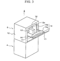
- FIG. 3 is a perspective view illustrating a state in which a hatch 11 of the artificial satellite 2 is opened.
- the artificial satellite 2 includes a bus portion 4 in which a bus device used for orbit correction or the like is contained, and a payload unit 6 in which a mission device unit 13, an antenna 14, and the like is contained, as a main configuration. Further, while a case in which the artificial satellite 2 has a rectangular exterior will be described in this embodiment, the present invention is not limited to this shape. Further, while a case in which the artificial satellite and an earth station communicate will be described in the following description, the present invention is not limited to such a use. While the artificial satellite has a variety of configurations, the bus device is not mentioned in the description of the artificial satellite of the present invention.
- the payload unit 6 includes a substantially rectangular housing, and a mission device unit 13 is contained in an internal space of the payload unit 6.
- the internal space of the payload unit 6 is referred to as a payload room 16, and a housing wall on the payload room 16 side is referred to as an inner wall surface.
- a hatch 11 is provided in a payload room wall 12. The hatch 11 can be opened or closed by a hatch opening and closing mechanism 17.
- the mission device unit 13 has a temperature range which is optimal for operation, but the mission device unit 13 generates heat when operating and the temperature thereof rises. Therefore, the heat of the mission device unit 13 must be dissipated. Since the artificial satellite 2 flies through cosmic space, the heat of the mission device unit 13 is mainly dissipated by thermal radiation.
- a material wall used to promote heat dissipation such as an OSR (optical solar reflector) is arranged in an outer wall (a wall surface on the cosmic space side) in the housing of the payload unit 6.
- OSR optical solar reflector
- the mission device unit 13 is installed near an inner wall surface of the housing of the payload unit 6 so that the heat of the mission device unit 13 is easily transferred to the outer wall.
- the heat emitted by the mission device unit 13 is dissipated substantially isotropically Therefore, when a plurality of mission device units 13 are densely arranged, there is a disadvantage in that the temperatures of the mission device units 13 rise due to heat from the other adjacent mission device units. Accordingly, the mission device units 13 are located near the wall and installed to be spaced so as not to cause thermal interference with the adjacent mission device units 13. Accordingly, it is necessary for the inner wall surface of the housing of the payload unit 6 to have an area corresponding to the installed mission device unit 13. Also, when the number of mission device units 13 increases, it is necessary for the inner wall of the housing to have a great area. As a result, an empty space is formed in a central room portion of the payload room 16.
- the dead space can be small.
- the inner wall of the payload unit 6 since it is necessary for the inner wall of the payload unit 6 to have a predetermined size in order to install the mission device unit 13 or the like as described above, the size of the payload unit 6 cannot be optionally reduced even when the payload room 16 has much dead space.
- the antenna since the antenna performs transmission or reception of signals through cosmic space, it is necessary for the antenna to be located outside the satellite at the time of communication. However, the antenna is not arranged outside the satellite at the time of launching of the artificial satellite 2. When the antenna is arranged outside the satellite at the time of launching, a protection means used to protect the antenna from shock during the launch is necessary, and therefore, it is desirable for the antenna not to be arranged outside the satellite at the time of launching.
- the payload room 16 is used as a chamber used to store the antenna 14 at the time of launching, and the antenna 14 is taken outside of the satellite at the time of communication. Therefore, the openable or closable hatch 11 is provided in the housing of the payload unit 6, and the antenna 14 is attached to this hatch 11. Also, when the antenna 14 is used, the antenna 14 can be drawn outside the satellite by opening the hatch 11.
- Such an antenna 14 includes a reflector 14a used to reflect electric waves such as microwaves, and a radiator 14b which inputs or outputs the electric waves. Also, at the time of reception, the reflector 14a reflects the electric waves so that the electric waves are input to the radiator 14b. Further, at the time of transmission, the reflector 14a reflects the electric waves emitted from the radiator 14b toward a target.
- an example of the antenna 14 is a fixed antenna. However, when transmission frequency decreases, the antenna 14 becomes larger. In such a case, a deployable antenna may be used.
- the hatch 11 is provided in the sidewall 12 of the housing of the payload unit 6 and is opened or closed by the hatch opening and closing mechanism 17. While the case in which the hatch 11 is provided in one sidewall 12 has been shown in FIG. 1 or the like, the hatches 11 may be provided in a plurality of sidewalls 12. A plurality of antennas 14 can be provided by providing a plurality of hatches 11. Therefore, there is the advantage in that the number of posture control processes used to adjust the direction of the antenna 14 with respect to a communication partner decreases.
- the hatch opening and closing mechanism 17 opens the hatch 11 based on a hatch opening command from the ground or the like, or automatically opens the hatch 11 according to a previously set program. Further, after the artificial satellite 2 assumes an orbit and the antenna 14 is installed outside the satellite, the antenna 14 is not contained. Therefore, the hatch opening and closing mechanism 17 may be configured to open the hatch using, for example, a spring.
- the reflector 14a is attached to the wall of the hatch 11 on the payload room 16 side, as illustrated in FIG. 3 . Further, the radiator 14b is attached to an upper end portion 12a of the payload room 16. Therefore, when the hatch 11 is opened, the reflector 14a is installed outside the satellite. Also, when the hatch 11 is opened, the degree of opening of the hatch 11 is set so that the radiator 14b is located in a focus position of the reflector 14a.
- the antenna 14 When such an artificial satellite 2 is launched, the antenna 14 is contained in the payload room 16, the hatch 11 is closed, and then the artificial satellite 2 is launched. Also, when the artificial satellite 2 assumes a predetermined orbit, the hatch 11 is opened by the hatch opening and closing mechanism 17. Accordingly, the antenna 14 springs out of the satellite and becomes able to perform communication.
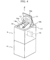
- the hatch 11 may be provided in the ceiling wall 12b of the payload room 16, as illustrated in FIG. 4 .
- the reflector 14a and the radiator 14b may be attached to the hatch 11 together, as illustrated in FIG. 4 .
- the radiator 14b is fixed to the hatch 11 via an arm 14c. Therefore, the relative position between the reflector 14a and the radiator 14b can be mechanically determined.
- the direction of the antenna 14 can be adjusted according to an output direction or a reception direction of the electric waves without performing posture control of the artificial satellite 2 by making the hatch opening and closing mechanism 17 controllable.
- the direction of the antenna 14 can be adjusted by adjusting the opening degree of the hatch 11 according to the output direction or the reception direction of the electric waves. Therefore, high quality communication can be realized.
- the artificial satellite in accordance with the present invention it is possible to miniaturize the artificial satellite without impairing the purpose and the function of the artificial satellite.
Landscapes
- Engineering & Computer Science (AREA)
- Remote Sensing (AREA)
- Aviation & Aerospace Engineering (AREA)
- Physics & Mathematics (AREA)
- Astronomy & Astrophysics (AREA)
- General Physics & Mathematics (AREA)
- Aerials With Secondary Devices (AREA)
- Support Of Aerials (AREA)
- Details Of Aerials (AREA)
- Radio Relay Systems (AREA)
Abstract
Description
- The present invention relates to an artificial satellite with an integrated antenna which is launched with the antenna stored in a main body of the satellite.
- An artificial satellite includes a bus portion on which a bus device or the like used for orbit control of the satellite itself is mounted, a payload unit in which a mission device unit responsible for a mission function of the satellite is contained, and the like. Also, an electronic device such as a communication apparatus, an antenna, or a measurement device is included in the mission device unit.
- In such an artificial satellite, miniaturization of the satellite itself is desired. However, since the antenna mounted on the artificial satellite is large, a method of mounting this antenna is important to miniaturization of the artificial satellite.
- For example, an artificial satellite including a
payload unit 101 and abus portion 102 as illustrated inFIG. 5 is disclosed in Japanese Unexamined Patent Application, First Publication No.2003-276699 payload unit 101 is formed to be smaller than that of thebus portion 102. Accordingly, thepayload unit 101 has a shape which is formed to concave with respect to thebus portion 102, and anantenna 105 is mounted in this concave place. Thus, the artificial satellite is miniaturized by forming the concave part of thepayload unit 101. - [Patent Document 1] Japanese Unexamined Patent Application, First Publication No.
2003-276699 - There is a problem associated with the artificial satellite in Japanese Unexamined Patent Application, First Publication No.
2003-276699 antenna 105 is provided outside the device (toward cosmic space). - In other words, when a mounting space for the
antenna 105 is secured by hollowing thepayload unit 101, it is assumed that the payload unit 10 can be made small. However, the payload unit is usually formed to have a required minimum size, and in order to reduce the size of the payload unit for the purpose of mounting the antenna, the amount of mission device units or the like contained in the payload unit must be reduced. As a result, the purpose of the artificial satellite may be limited. - Therefore, one object of the present invention is to provide an artificial satellite with an integrated antenna which is miniaturized while satisfying the purpose or the function of the artificial satellite.
- In order to solve the above problems, an artificial satellite of the present invention is characterized in that the artificial satellite includes at least one hatch provided in a wall which forms an empty space (dead space) inside the artificial satellite; and a hatch opening and closing mechanism which opens this hatch, wherein the antenna is attached to the hatch.
- According to the artificial satellite of the present invention, since the antenna is contained in a dead space inside the artificial satellite, it is possible to miniaturize the artificial satellite without reducing the size of the payload unit for mounting the antenna.
-
-
FIG. 1 is a schematic perspective view of an artificial satellite in an embodiment according to the present invention. -
FIG. 2 is a cross-sectional view taken along a line A-A in the artificial satellite ofFIG 1 . -
FIG. 3 is a perspective view in the artificial satellite in a state in which a hatch is opened. -
FIG. 4 is a perspective view of the artificial satellite when the hatch is provided in a ceiling wall of a payload unit. -
FIG. 5 is a perspective view of an artificial satellite applied to the description of related art. - One embodiment of the present invention will be described. Further, in the description of in this embodiment, while an example of a dead space present in an artificial satellite includes a dead space in a payload unit, the present invention is not limited to such a dead space.
-
FIG. 1 is a schematic perspective view of anartificial satellite 2 according to the present invention.FIG. 2 illustrates a cross-sectional view taken along a line A-A in theartificial satellite 2 ofFIG. 1 .FIG. 3 is a perspective view illustrating a state in which ahatch 11 of theartificial satellite 2 is opened. - The
artificial satellite 2 includes abus portion 4 in which a bus device used for orbit correction or the like is contained, and apayload unit 6 in which amission device unit 13, anantenna 14, and the like is contained, as a main configuration. Further, while a case in which theartificial satellite 2 has a rectangular exterior will be described in this embodiment, the present invention is not limited to this shape. Further, while a case in which the artificial satellite and an earth station communicate will be described in the following description, the present invention is not limited to such a use. While the artificial satellite has a variety of configurations, the bus device is not mentioned in the description of the artificial satellite of the present invention. - The
payload unit 6 includes a substantially rectangular housing, and amission device unit 13 is contained in an internal space of thepayload unit 6. Hereinafter, the internal space of thepayload unit 6 is referred to as apayload room 16, and a housing wall on thepayload room 16 side is referred to as an inner wall surface. Further, ahatch 11 is provided in apayload room wall 12. Thehatch 11 can be opened or closed by a hatch opening andclosing mechanism 17. - Various measurement devices, communication devices, control devices, the
antenna 14, the hatch opening andclosing mechanism 17 and the like are included in themission device unit 13. - Generally, the
mission device unit 13 has a temperature range which is optimal for operation, but themission device unit 13 generates heat when operating and the temperature thereof rises. Therefore, the heat of themission device unit 13 must be dissipated. Since theartificial satellite 2 flies through cosmic space, the heat of themission device unit 13 is mainly dissipated by thermal radiation. - Therefore, in order to efficiently radiate the heat of the
mission device unit 13 into cosmic space, a material wall used to promote heat dissipation, such as an OSR (optical solar reflector), is arranged in an outer wall (a wall surface on the cosmic space side) in the housing of thepayload unit 6. Also, themission device unit 13 is installed near an inner wall surface of the housing of thepayload unit 6 so that the heat of themission device unit 13 is easily transferred to the outer wall. - Further, the heat emitted by the
mission device unit 13 is dissipated substantially isotropically Therefore, when a plurality ofmission device units 13 are densely arranged, there is a disadvantage in that the temperatures of themission device units 13 rise due to heat from the other adjacent mission device units. Accordingly, themission device units 13 are located near the wall and installed to be spaced so as not to cause thermal interference with the adjacentmission device units 13. Accordingly, it is necessary for the inner wall surface of the housing of thepayload unit 6 to have an area corresponding to the installedmission device unit 13. Also, when the number ofmission device units 13 increases, it is necessary for the inner wall of the housing to have a great area. As a result, an empty space is formed in a central room portion of thepayload room 16. - In this
artificial satellite 2, arrangement of a fuel tank or the like is performed to effectively use such dead space. However, since the fuel tank can be moved to and arranged in thebus portion 4 according to advances in technology for miniaturization of an engine, miniaturization of the fuel tank, or the like, the dead space in thepayload room 16 continues to increase. - If the
payload room 16 is small, the dead space can be small. However, since it is necessary for the inner wall of thepayload unit 6 to have a predetermined size in order to install themission device unit 13 or the like as described above, the size of thepayload unit 6 cannot be optionally reduced even when thepayload room 16 has much dead space. - On the other hand, since the antenna performs transmission or reception of signals through cosmic space, it is necessary for the antenna to be located outside the satellite at the time of communication. However, the antenna is not arranged outside the satellite at the time of launching of the
artificial satellite 2. When the antenna is arranged outside the satellite at the time of launching, a protection means used to protect the antenna from shock during the launch is necessary, and therefore, it is desirable for the antenna not to be arranged outside the satellite at the time of launching. - Therefore, in the artificial satellite according to the present invention, production of much dead space in the
payload room 16 is noted, thepayload room 16 is used as a chamber used to store theantenna 14 at the time of launching, and theantenna 14 is taken outside of the satellite at the time of communication. Therefore, the openable orclosable hatch 11 is provided in the housing of thepayload unit 6, and theantenna 14 is attached to thishatch 11. Also, when theantenna 14 is used, theantenna 14 can be drawn outside the satellite by opening thehatch 11. - Such an
antenna 14 includes areflector 14a used to reflect electric waves such as microwaves, and aradiator 14b which inputs or outputs the electric waves. Also, at the time of reception, thereflector 14a reflects the electric waves so that the electric waves are input to theradiator 14b. Further, at the time of transmission, thereflector 14a reflects the electric waves emitted from theradiator 14b toward a target. In the following description, an example of theantenna 14 is a fixed antenna. However, when transmission frequency decreases, theantenna 14 becomes larger. In such a case, a deployable antenna may be used. - The
hatch 11 is provided in thesidewall 12 of the housing of thepayload unit 6 and is opened or closed by the hatch opening andclosing mechanism 17. While the case in which thehatch 11 is provided in onesidewall 12 has been shown inFIG. 1 or the like, thehatches 11 may be provided in a plurality ofsidewalls 12. A plurality ofantennas 14 can be provided by providing a plurality ofhatches 11. Therefore, there is the advantage in that the number of posture control processes used to adjust the direction of theantenna 14 with respect to a communication partner decreases. - The hatch opening and
closing mechanism 17 opens thehatch 11 based on a hatch opening command from the ground or the like, or automatically opens thehatch 11 according to a previously set program. Further, after theartificial satellite 2 assumes an orbit and theantenna 14 is installed outside the satellite, theantenna 14 is not contained. Therefore, the hatch opening andclosing mechanism 17 may be configured to open the hatch using, for example, a spring. - Also, the
reflector 14a is attached to the wall of thehatch 11 on thepayload room 16 side, as illustrated inFIG. 3 . Further, theradiator 14b is attached to anupper end portion 12a of thepayload room 16. Therefore, when thehatch 11 is opened, thereflector 14a is installed outside the satellite. Also, when thehatch 11 is opened, the degree of opening of thehatch 11 is set so that theradiator 14b is located in a focus position of thereflector 14a. - When such an
artificial satellite 2 is launched, theantenna 14 is contained in thepayload room 16, thehatch 11 is closed, and then theartificial satellite 2 is launched. Also, when theartificial satellite 2 assumes a predetermined orbit, thehatch 11 is opened by the hatch opening andclosing mechanism 17. Accordingly, theantenna 14 springs out of the satellite and becomes able to perform communication. - As described above, it is not necessary to reduce the area of the inner wall in which the
mission device unit 13 is arranged in close proximity to other units since the artificial satellite is launched with theantenna 14 stored in the dead space of thepayload room 16. In other words, it is possible to miniaturize theartificial satellite 2 while satisfying the purpose and the function of the artificial satellite. - Further, although the case in which the
hatch 11 is provided in thesidewall 12 of thepayload room 16 has been described in the above description, thehatch 11 may be provided in theceiling wall 12b of thepayload room 16, as illustrated inFIG. 4 . - Further, while the relative position of the
reflector 14a and theradiator 14b is adjusted based on the opening or closing degree of thehatch 11, thereflector 14a and theradiator 14b may be attached to thehatch 11 together, as illustrated inFIG. 4 . In this case, theradiator 14b is fixed to thehatch 11 via anarm 14c. Therefore, the relative position between thereflector 14a and theradiator 14b can be mechanically determined. - Further, the direction of the
antenna 14 can be adjusted according to an output direction or a reception direction of the electric waves without performing posture control of theartificial satellite 2 by making the hatch opening andclosing mechanism 17 controllable. In other words, the direction of theantenna 14 can be adjusted by adjusting the opening degree of thehatch 11 according to the output direction or the reception direction of the electric waves. Therefore, high quality communication can be realized. - Priority is claimed on Japanese Patent Application No.
2011-240400, filed November 1, 2011 - According to the artificial satellite in accordance with the present invention, it is possible to miniaturize the artificial satellite without impairing the purpose and the function of the artificial satellite.
-
- 2
- artificial satellite
- 4
- bus portion
- 6
- payload unit
- 11
- hatch
- 12
- sidewall (payload room wall)
- 12a
- upper end portion
- 12b
- ceiling wall
- 13
- mission device unit
- 14
- antenna
- 14a
- reflector
- 14b
- radiator
- 14c
- arm
- 16
- payload room
Claims (6)
- An artificial satellite having an antenna mounted thereon, the artificial satellite comprising:at least one hatch formed in a wall which partitions a dead space of the artificial satellite; anda hatch opening and closing mechanism which opens the hatch,wherein the antenna is attached to the hatch.
- The artificial satellite according to claim 1,
wherein the hatch is provided in one of a ceiling wall and a sidewall of a payload unit in which a mission device unit which executes a mission function of the artificial satellite is contained. - The artificial satellite according to claim 1 or 2,
wherein the antenna includes a reflector and a radiator, and the reflector and the radiator are attached to the hatch. - The artificial satellite according to claim 1 or 2,
wherein the antenna includes a reflector and a radiator,
the reflector is attached to the hatch, and the radiator is attached to a wall in which the hatch is opened or closed in the payload room. - The artificial satellite according to any one of claims 1 to 4,
wherein the hatch opening and closing mechanism opens the hatch by a predetermined amount. - The artificial satellite according to any one of claims 1 to 4, wherein the hatch opening and closing mechanism adjusts a degree of opening of the hatch.
Applications Claiming Priority (2)
| Application Number | Priority Date | Filing Date | Title |
|---|---|---|---|
| JP2011240400 | 2011-11-01 | ||
| PCT/JP2012/078134 WO2013065722A1 (en) | 2011-11-01 | 2012-10-31 | Artificial satellite with integrated antenna |
Publications (3)
| Publication Number | Publication Date |
|---|---|
| EP2774856A1 true EP2774856A1 (en) | 2014-09-10 |
| EP2774856A4 EP2774856A4 (en) | 2015-06-24 |
| EP2774856B1 EP2774856B1 (en) | 2023-09-27 |
Family
ID=48192067
Family Applications (1)
| Application Number | Title | Priority Date | Filing Date |
|---|---|---|---|
| EP12845914.6A Active EP2774856B1 (en) | 2011-11-01 | 2012-10-31 | Artificial satellite with integrated antenna |
Country Status (8)
| Country | Link |
|---|---|
| US (1) | US9887452B2 (en) |
| EP (1) | EP2774856B1 (en) |
| JP (1) | JP5915663B2 (en) |
| AU (2) | AU2012333556A1 (en) |
| CA (1) | CA2853516C (en) |
| IN (1) | IN2014CN03852A (en) |
| RU (1) | RU2607928C2 (en) |
| WO (1) | WO2013065722A1 (en) |
Families Citing this family (4)
| Publication number | Priority date | Publication date | Assignee | Title |
|---|---|---|---|---|
| EP4462601A3 (en) | 2010-12-15 | 2025-02-19 | Planet Labs PBC | Integrated antenna system for imaging microsatellites |
| KR101537355B1 (en) * | 2013-12-10 | 2015-07-17 | 한국항공우주연구원 | Antenna module for Cube type satellite |
| JP7382894B2 (en) * | 2020-04-21 | 2023-11-17 | 三菱電機株式会社 | Observation systems, communication satellites and observation satellites |
| KR102289298B1 (en) * | 2020-11-26 | 2021-08-12 | 한화시스템 주식회사 | Transmitting/receiving apparatus and satellite having the same |
Family Cites Families (18)
| Publication number | Priority date | Publication date | Assignee | Title |
|---|---|---|---|---|
| DE2656691C3 (en) | 1976-12-15 | 1980-10-02 | Messerschmitt-Boelkow-Blohm Gmbh, 8000 Muenchen | Satellite antenna |
| US4684952A (en) * | 1982-09-24 | 1987-08-04 | Ball Corporation | Microstrip reflectarray for satellite communication and radar cross-section enhancement or reduction |
| JPS5978709U (en) | 1982-11-16 | 1984-05-28 | 三菱電機株式会社 | Antenna for satellite |
| JPS5991018U (en) | 1982-12-09 | 1984-06-20 | 三菱電機株式会社 | geostationary communication satellite |
| US4465951A (en) | 1983-03-21 | 1984-08-14 | Satellite Business Systems | Backup bearing and power transfer assembly for communication satellite |
| JPS63147013U (en) * | 1987-03-19 | 1988-09-28 | ||
| ATE143734T1 (en) | 1990-07-24 | 1996-10-15 | Staffan Gunnarsson | SYSTEM FOR POSITIONING A FIRST OBJECT WITH RESPECT TO A SECOND OBJECT |
| JPH04275705A (en) | 1991-03-04 | 1992-10-01 | Nissan Motor Co Ltd | Built-in antenna for automobile |
| US6019475A (en) * | 1994-09-30 | 2000-02-01 | Donnelly Corporation | Modular rearview mirror assembly including an electronic control module |
| KR100193851B1 (en) | 1996-11-05 | 1999-06-15 | 윤종용 | Small antenna of portable radio |
| JP2003276699A (en) | 2002-03-27 | 2003-10-02 | Mitsubishi Electric Corp | Artificial satellite |
| JP4055620B2 (en) | 2003-03-26 | 2008-03-05 | マツダ株式会社 | Vehicle antenna device |
| JP4639141B2 (en) | 2005-11-18 | 2011-02-23 | 株式会社ホンダロック | Antenna built-in device |
| JP2009190661A (en) * | 2008-02-18 | 2009-08-27 | Mitsubishi Electric Corp | Protective cover for optical equipment |
| FR2928063B1 (en) | 2008-02-26 | 2011-02-18 | Airbus France | DEVICE FOR WIRELESS, HIGH-SPEED POINT-TO-DATA DOT TRANSMISSION BETWEEN A VEHICLE IN PARKING AND A FIXED INFRASTRUCTURE |
| ES2389636T3 (en) * | 2008-03-18 | 2012-10-29 | Astrium Limited | Antenna power set |
| EP4462601A3 (en) * | 2010-12-15 | 2025-02-19 | Planet Labs PBC | Integrated antenna system for imaging microsatellites |
| RU104387U1 (en) | 2011-02-14 | 2011-05-10 | Открытое акционерное общество "Научно-производственное предприятие "Рубин" (ОАО "НПП "Рубин") | MOBILE ANTENNA DEVICE |
-
2012
- 2012-10-31 EP EP12845914.6A patent/EP2774856B1/en active Active
- 2012-10-31 JP JP2013541809A patent/JP5915663B2/en not_active Expired - Fee Related
- 2012-10-31 IN IN3852CHN2014 patent/IN2014CN03852A/en unknown
- 2012-10-31 US US14/353,543 patent/US9887452B2/en not_active Expired - Fee Related
- 2012-10-31 RU RU2014121203A patent/RU2607928C2/en active
- 2012-10-31 WO PCT/JP2012/078134 patent/WO2013065722A1/en not_active Ceased
- 2012-10-31 CA CA2853516A patent/CA2853516C/en active Active
- 2012-10-31 AU AU2012333556A patent/AU2012333556A1/en not_active Abandoned
-
2016
- 2016-04-19 AU AU2016202486A patent/AU2016202486B2/en not_active Ceased
Also Published As
| Publication number | Publication date |
|---|---|
| US20140292594A1 (en) | 2014-10-02 |
| WO2013065722A1 (en) | 2013-05-10 |
| RU2014121203A (en) | 2015-12-10 |
| JPWO2013065722A1 (en) | 2015-04-02 |
| IN2014CN03852A (en) | 2015-09-04 |
| AU2012333556A1 (en) | 2014-05-15 |
| AU2016202486A1 (en) | 2016-05-12 |
| AU2016202486B2 (en) | 2017-11-02 |
| EP2774856A4 (en) | 2015-06-24 |
| US9887452B2 (en) | 2018-02-06 |
| CA2853516C (en) | 2018-10-16 |
| EP2774856B1 (en) | 2023-09-27 |
| JP5915663B2 (en) | 2016-05-11 |
| RU2607928C2 (en) | 2017-01-11 |
| CA2853516A1 (en) | 2013-05-10 |
Similar Documents
| Publication | Publication Date | Title |
|---|---|---|
| AU2016202486B2 (en) | Artificial satellite with integrated antenna | |
| US8362963B2 (en) | Satellite transmission antenna and satellite-based mobile telecommunication station | |
| CN112913078B (en) | Antenna module and vehicle | |
| US9685713B2 (en) | Antenna device | |
| US11043750B2 (en) | Antenna | |
| EP2040330A1 (en) | Reconfigurable reflector for electromagnetic waves | |
| EP3561950A1 (en) | Electronic apparatus | |
| US8890765B1 (en) | Antenna having an active radome | |
| KR20140043333A (en) | Beam shape control device for an antenna and associated antenna | |
| WO2014209470A2 (en) | Integrated antenna and antenna component | |
| JP2008187628A (en) | Deployment antenna | |
| JP2009141983A (en) | An antenna device using an omnidirectional dielectric lens. | |
| EP3227958A1 (en) | Antenna radome with absorbers | |
| JP6952215B2 (en) | Spacecraft, launchers, and spacecraft stacks | |
| RU2713050C1 (en) | Conformal spiral antenna | |
| KR101088017B1 (en) | Patched Antenna Unit Mounted on Cylindrical Aircraft | |
| JP7179197B2 (en) | space vehicle | |
| CN113228414B (en) | Antenna, microwave equipment and communication system | |
| US20240097344A1 (en) | Reflector antenna and antenna aperture expansion method | |
| US20190123445A1 (en) | Electronic device | |
| KR102055825B1 (en) | Dielectric Insertion Type Waveguide Slot Array Antenna | |
| JP7207821B2 (en) | Artificial satellite equipped with high-frequency equipment and manufacturing method thereof | |
| KR20240057331A (en) | Camera module integrated antenna | |
| KR20230043464A (en) | High-resolution multi-reflection optical system mounted on satellite | |
| US20170110794A1 (en) | Compact antenna with modular beam aperture |
Legal Events
| Date | Code | Title | Description |
|---|---|---|---|
| PUAI | Public reference made under article 153(3) epc to a published international application that has entered the european phase |
Free format text: ORIGINAL CODE: 0009012 |
|
| 17P | Request for examination filed |
Effective date: 20140528 |
|
| AK | Designated contracting states |
Kind code of ref document: A1 Designated state(s): AL AT BE BG CH CY CZ DE DK EE ES FI FR GB GR HR HU IE IS IT LI LT LU LV MC MK MT NL NO PL PT RO RS SE SI SK SM TR |
|
| DAX | Request for extension of the european patent (deleted) | ||
| RA4 | Supplementary search report drawn up and despatched (corrected) |
Effective date: 20150526 |
|
| RIC1 | Information provided on ipc code assigned before grant |
Ipc: B64G 1/66 20060101AFI20150519BHEP Ipc: H01Q 1/28 20060101ALI20150519BHEP |
|
| STAA | Information on the status of an ep patent application or granted ep patent |
Free format text: STATUS: EXAMINATION IS IN PROGRESS |
|
| 17Q | First examination report despatched |
Effective date: 20171122 |
|
| GRAP | Despatch of communication of intention to grant a patent |
Free format text: ORIGINAL CODE: EPIDOSNIGR1 |
|
| STAA | Information on the status of an ep patent application or granted ep patent |
Free format text: STATUS: GRANT OF PATENT IS INTENDED |
|
| INTG | Intention to grant announced |
Effective date: 20230602 |
|
| GRAS | Grant fee paid |
Free format text: ORIGINAL CODE: EPIDOSNIGR3 |
|
| GRAA | (expected) grant |
Free format text: ORIGINAL CODE: 0009210 |
|
| STAA | Information on the status of an ep patent application or granted ep patent |
Free format text: STATUS: THE PATENT HAS BEEN GRANTED |
|
| AK | Designated contracting states |
Kind code of ref document: B1 Designated state(s): AL AT BE BG CH CY CZ DE DK EE ES FI FR GB GR HR HU IE IS IT LI LT LU LV MC MK MT NL NO PL PT RO RS SE SI SK SM TR |
|
| REG | Reference to a national code |
Ref country code: GB Ref legal event code: FG4D |
|
| REG | Reference to a national code |
Ref country code: CH Ref legal event code: EP |
|
| REG | Reference to a national code |
Ref country code: DE Ref legal event code: R096 Ref document number: 602012080136 Country of ref document: DE |
|
| REG | Reference to a national code |
Ref country code: IE Ref legal event code: FG4D |
|
| REG | Reference to a national code |
Ref country code: LT Ref legal event code: MG9D |
|
| PG25 | Lapsed in a contracting state [announced via postgrant information from national office to epo] |
Ref country code: GR Free format text: LAPSE BECAUSE OF FAILURE TO SUBMIT A TRANSLATION OF THE DESCRIPTION OR TO PAY THE FEE WITHIN THE PRESCRIBED TIME-LIMIT Effective date: 20231228 |
|
| PG25 | Lapsed in a contracting state [announced via postgrant information from national office to epo] |
Ref country code: SE Free format text: LAPSE BECAUSE OF FAILURE TO SUBMIT A TRANSLATION OF THE DESCRIPTION OR TO PAY THE FEE WITHIN THE PRESCRIBED TIME-LIMIT Effective date: 20230927 Ref country code: RS Free format text: LAPSE BECAUSE OF FAILURE TO SUBMIT A TRANSLATION OF THE DESCRIPTION OR TO PAY THE FEE WITHIN THE PRESCRIBED TIME-LIMIT Effective date: 20230927 Ref country code: NO Free format text: LAPSE BECAUSE OF FAILURE TO SUBMIT A TRANSLATION OF THE DESCRIPTION OR TO PAY THE FEE WITHIN THE PRESCRIBED TIME-LIMIT Effective date: 20231227 Ref country code: LV Free format text: LAPSE BECAUSE OF FAILURE TO SUBMIT A TRANSLATION OF THE DESCRIPTION OR TO PAY THE FEE WITHIN THE PRESCRIBED TIME-LIMIT Effective date: 20230927 Ref country code: LT Free format text: LAPSE BECAUSE OF FAILURE TO SUBMIT A TRANSLATION OF THE DESCRIPTION OR TO PAY THE FEE WITHIN THE PRESCRIBED TIME-LIMIT Effective date: 20230927 Ref country code: HR Free format text: LAPSE BECAUSE OF FAILURE TO SUBMIT A TRANSLATION OF THE DESCRIPTION OR TO PAY THE FEE WITHIN THE PRESCRIBED TIME-LIMIT Effective date: 20230927 Ref country code: GR Free format text: LAPSE BECAUSE OF FAILURE TO SUBMIT A TRANSLATION OF THE DESCRIPTION OR TO PAY THE FEE WITHIN THE PRESCRIBED TIME-LIMIT Effective date: 20231228 Ref country code: FI Free format text: LAPSE BECAUSE OF FAILURE TO SUBMIT A TRANSLATION OF THE DESCRIPTION OR TO PAY THE FEE WITHIN THE PRESCRIBED TIME-LIMIT Effective date: 20230927 |
|
| PGFP | Annual fee paid to national office [announced via postgrant information from national office to epo] |
Ref country code: FR Payment date: 20231120 Year of fee payment: 12 |
|
| REG | Reference to a national code |
Ref country code: NL Ref legal event code: MP Effective date: 20230927 |
|
| REG | Reference to a national code |
Ref country code: AT Ref legal event code: MK05 Ref document number: 1615199 Country of ref document: AT Kind code of ref document: T Effective date: 20230927 |
|
| PG25 | Lapsed in a contracting state [announced via postgrant information from national office to epo] |
Ref country code: NL Free format text: LAPSE BECAUSE OF FAILURE TO SUBMIT A TRANSLATION OF THE DESCRIPTION OR TO PAY THE FEE WITHIN THE PRESCRIBED TIME-LIMIT Effective date: 20230927 |
|
| PG25 | Lapsed in a contracting state [announced via postgrant information from national office to epo] |
Ref country code: IS Free format text: LAPSE BECAUSE OF FAILURE TO SUBMIT A TRANSLATION OF THE DESCRIPTION OR TO PAY THE FEE WITHIN THE PRESCRIBED TIME-LIMIT Effective date: 20240127 |
|
| PG25 | Lapsed in a contracting state [announced via postgrant information from national office to epo] |
Ref country code: AT Free format text: LAPSE BECAUSE OF FAILURE TO SUBMIT A TRANSLATION OF THE DESCRIPTION OR TO PAY THE FEE WITHIN THE PRESCRIBED TIME-LIMIT Effective date: 20230927 |
|
| PG25 | Lapsed in a contracting state [announced via postgrant information from national office to epo] |
Ref country code: ES Free format text: LAPSE BECAUSE OF FAILURE TO SUBMIT A TRANSLATION OF THE DESCRIPTION OR TO PAY THE FEE WITHIN THE PRESCRIBED TIME-LIMIT Effective date: 20230927 |
|
| PG25 | Lapsed in a contracting state [announced via postgrant information from national office to epo] |
Ref country code: SM Free format text: LAPSE BECAUSE OF FAILURE TO SUBMIT A TRANSLATION OF THE DESCRIPTION OR TO PAY THE FEE WITHIN THE PRESCRIBED TIME-LIMIT Effective date: 20230927 Ref country code: RO Free format text: LAPSE BECAUSE OF FAILURE TO SUBMIT A TRANSLATION OF THE DESCRIPTION OR TO PAY THE FEE WITHIN THE PRESCRIBED TIME-LIMIT Effective date: 20230927 Ref country code: IS Free format text: LAPSE BECAUSE OF FAILURE TO SUBMIT A TRANSLATION OF THE DESCRIPTION OR TO PAY THE FEE WITHIN THE PRESCRIBED TIME-LIMIT Effective date: 20240127 Ref country code: ES Free format text: LAPSE BECAUSE OF FAILURE TO SUBMIT A TRANSLATION OF THE DESCRIPTION OR TO PAY THE FEE WITHIN THE PRESCRIBED TIME-LIMIT Effective date: 20230927 Ref country code: EE Free format text: LAPSE BECAUSE OF FAILURE TO SUBMIT A TRANSLATION OF THE DESCRIPTION OR TO PAY THE FEE WITHIN THE PRESCRIBED TIME-LIMIT Effective date: 20230927 Ref country code: CZ Free format text: LAPSE BECAUSE OF FAILURE TO SUBMIT A TRANSLATION OF THE DESCRIPTION OR TO PAY THE FEE WITHIN THE PRESCRIBED TIME-LIMIT Effective date: 20230927 Ref country code: AT Free format text: LAPSE BECAUSE OF FAILURE TO SUBMIT A TRANSLATION OF THE DESCRIPTION OR TO PAY THE FEE WITHIN THE PRESCRIBED TIME-LIMIT Effective date: 20230927 Ref country code: PT Free format text: LAPSE BECAUSE OF FAILURE TO SUBMIT A TRANSLATION OF THE DESCRIPTION OR TO PAY THE FEE WITHIN THE PRESCRIBED TIME-LIMIT Effective date: 20240129 Ref country code: SK Free format text: LAPSE BECAUSE OF FAILURE TO SUBMIT A TRANSLATION OF THE DESCRIPTION OR TO PAY THE FEE WITHIN THE PRESCRIBED TIME-LIMIT Effective date: 20230927 |
|
| REG | Reference to a national code |
Ref country code: DE Ref legal event code: R119 Ref document number: 602012080136 Country of ref document: DE |
|
| PG25 | Lapsed in a contracting state [announced via postgrant information from national office to epo] |
Ref country code: PL Free format text: LAPSE BECAUSE OF FAILURE TO SUBMIT A TRANSLATION OF THE DESCRIPTION OR TO PAY THE FEE WITHIN THE PRESCRIBED TIME-LIMIT Effective date: 20230927 Ref country code: IT Free format text: LAPSE BECAUSE OF FAILURE TO SUBMIT A TRANSLATION OF THE DESCRIPTION OR TO PAY THE FEE WITHIN THE PRESCRIBED TIME-LIMIT Effective date: 20230927 |
|
| REG | Reference to a national code |
Ref country code: CH Ref legal event code: PL |
|
| REG | Reference to a national code |
Ref country code: BE Ref legal event code: MM Effective date: 20231031 |
|
| PG25 | Lapsed in a contracting state [announced via postgrant information from national office to epo] |
Ref country code: LU Free format text: LAPSE BECAUSE OF NON-PAYMENT OF DUE FEES Effective date: 20231031 |
|
| PG25 | Lapsed in a contracting state [announced via postgrant information from national office to epo] |
Ref country code: LU Free format text: LAPSE BECAUSE OF NON-PAYMENT OF DUE FEES Effective date: 20231031 |
|
| PG25 | Lapsed in a contracting state [announced via postgrant information from national office to epo] |
Ref country code: MC Free format text: LAPSE BECAUSE OF FAILURE TO SUBMIT A TRANSLATION OF THE DESCRIPTION OR TO PAY THE FEE WITHIN THE PRESCRIBED TIME-LIMIT Effective date: 20230927 |
|
| PG25 | Lapsed in a contracting state [announced via postgrant information from national office to epo] |
Ref country code: DK Free format text: LAPSE BECAUSE OF FAILURE TO SUBMIT A TRANSLATION OF THE DESCRIPTION OR TO PAY THE FEE WITHIN THE PRESCRIBED TIME-LIMIT Effective date: 20230927 |
|
| PG25 | Lapsed in a contracting state [announced via postgrant information from national office to epo] |
Ref country code: CH Free format text: LAPSE BECAUSE OF NON-PAYMENT OF DUE FEES Effective date: 20231031 |
|
| PG25 | Lapsed in a contracting state [announced via postgrant information from national office to epo] |
Ref country code: MC Free format text: LAPSE BECAUSE OF FAILURE TO SUBMIT A TRANSLATION OF THE DESCRIPTION OR TO PAY THE FEE WITHIN THE PRESCRIBED TIME-LIMIT Effective date: 20230927 Ref country code: DK Free format text: LAPSE BECAUSE OF FAILURE TO SUBMIT A TRANSLATION OF THE DESCRIPTION OR TO PAY THE FEE WITHIN THE PRESCRIBED TIME-LIMIT Effective date: 20230927 Ref country code: DE Free format text: LAPSE BECAUSE OF NON-PAYMENT OF DUE FEES Effective date: 20240501 Ref country code: CH Free format text: LAPSE BECAUSE OF NON-PAYMENT OF DUE FEES Effective date: 20231031 |
|
| PLBE | No opposition filed within time limit |
Free format text: ORIGINAL CODE: 0009261 |
|
| STAA | Information on the status of an ep patent application or granted ep patent |
Free format text: STATUS: NO OPPOSITION FILED WITHIN TIME LIMIT |
|
| GBPC | Gb: european patent ceased through non-payment of renewal fee |
Effective date: 20231227 |
|
| PG25 | Lapsed in a contracting state [announced via postgrant information from national office to epo] |
Ref country code: BE Free format text: LAPSE BECAUSE OF NON-PAYMENT OF DUE FEES Effective date: 20231031 |
|
| 26N | No opposition filed |
Effective date: 20240628 |
|
| PG25 | Lapsed in a contracting state [announced via postgrant information from national office to epo] |
Ref country code: IE Free format text: LAPSE BECAUSE OF NON-PAYMENT OF DUE FEES Effective date: 20231031 |
|
| PG25 | Lapsed in a contracting state [announced via postgrant information from national office to epo] |
Ref country code: GB Free format text: LAPSE BECAUSE OF NON-PAYMENT OF DUE FEES Effective date: 20231227 |
|
| PG25 | Lapsed in a contracting state [announced via postgrant information from national office to epo] |
Ref country code: SI Free format text: LAPSE BECAUSE OF FAILURE TO SUBMIT A TRANSLATION OF THE DESCRIPTION OR TO PAY THE FEE WITHIN THE PRESCRIBED TIME-LIMIT Effective date: 20230927 |
|
| PG25 | Lapsed in a contracting state [announced via postgrant information from national office to epo] |
Ref country code: SI Free format text: LAPSE BECAUSE OF FAILURE TO SUBMIT A TRANSLATION OF THE DESCRIPTION OR TO PAY THE FEE WITHIN THE PRESCRIBED TIME-LIMIT Effective date: 20230927 Ref country code: IE Free format text: LAPSE BECAUSE OF NON-PAYMENT OF DUE FEES Effective date: 20231031 Ref country code: GB Free format text: LAPSE BECAUSE OF NON-PAYMENT OF DUE FEES Effective date: 20231227 |
|
| PG25 | Lapsed in a contracting state [announced via postgrant information from national office to epo] |
Ref country code: BG Free format text: LAPSE BECAUSE OF FAILURE TO SUBMIT A TRANSLATION OF THE DESCRIPTION OR TO PAY THE FEE WITHIN THE PRESCRIBED TIME-LIMIT Effective date: 20230927 |
|
| PG25 | Lapsed in a contracting state [announced via postgrant information from national office to epo] |
Ref country code: BG Free format text: LAPSE BECAUSE OF FAILURE TO SUBMIT A TRANSLATION OF THE DESCRIPTION OR TO PAY THE FEE WITHIN THE PRESCRIBED TIME-LIMIT Effective date: 20230927 |
|
| PG25 | Lapsed in a contracting state [announced via postgrant information from national office to epo] |
Ref country code: FR Free format text: LAPSE BECAUSE OF NON-PAYMENT OF DUE FEES Effective date: 20241031 |
|
| PG25 | Lapsed in a contracting state [announced via postgrant information from national office to epo] |
Ref country code: CY Free format text: LAPSE BECAUSE OF FAILURE TO SUBMIT A TRANSLATION OF THE DESCRIPTION OR TO PAY THE FEE WITHIN THE PRESCRIBED TIME-LIMIT; INVALID AB INITIO Effective date: 20121031 |
|
| PG25 | Lapsed in a contracting state [announced via postgrant information from national office to epo] |
Ref country code: HU Free format text: LAPSE BECAUSE OF FAILURE TO SUBMIT A TRANSLATION OF THE DESCRIPTION OR TO PAY THE FEE WITHIN THE PRESCRIBED TIME-LIMIT; INVALID AB INITIO Effective date: 20121031 |
|
| PG25 | Lapsed in a contracting state [announced via postgrant information from national office to epo] |
Ref country code: TR Free format text: LAPSE BECAUSE OF FAILURE TO SUBMIT A TRANSLATION OF THE DESCRIPTION OR TO PAY THE FEE WITHIN THE PRESCRIBED TIME-LIMIT Effective date: 20230927 |