EP2774643A1 - Injection needle - Google Patents
Injection needle Download PDFInfo
- Publication number
- EP2774643A1 EP2774643A1 EP12846777.6A EP12846777A EP2774643A1 EP 2774643 A1 EP2774643 A1 EP 2774643A1 EP 12846777 A EP12846777 A EP 12846777A EP 2774643 A1 EP2774643 A1 EP 2774643A1
- Authority
- EP
- European Patent Office
- Prior art keywords
- injection needle
- present
- distal end
- molybdenum
- conventional product
- Prior art date
- Legal status (The legal status is an assumption and is not a legal conclusion. Google has not performed a legal analysis and makes no representation as to the accuracy of the status listed.)
- Withdrawn
Links
Images





Classifications
-
- A—HUMAN NECESSITIES
- A61—MEDICAL OR VETERINARY SCIENCE; HYGIENE
- A61M—DEVICES FOR INTRODUCING MEDIA INTO, OR ONTO, THE BODY; DEVICES FOR TRANSDUCING BODY MEDIA OR FOR TAKING MEDIA FROM THE BODY; DEVICES FOR PRODUCING OR ENDING SLEEP OR STUPOR
- A61M5/00—Devices for bringing media into the body in a subcutaneous, intra-vascular or intramuscular way; Accessories therefor, e.g. filling or cleaning devices, arm-rests
- A61M5/178—Syringes
- A61M5/31—Details
- A61M5/32—Needles; Details of needles pertaining to their connection with syringe or hub; Accessories for bringing the needle into, or holding the needle on, the body; Devices for protection of needles
- A61M5/3286—Needle tip design, e.g. for improved penetration
-
- A—HUMAN NECESSITIES
- A61—MEDICAL OR VETERINARY SCIENCE; HYGIENE
- A61L—METHODS OR APPARATUS FOR STERILISING MATERIALS OR OBJECTS IN GENERAL; DISINFECTION, STERILISATION OR DEODORISATION OF AIR; CHEMICAL ASPECTS OF BANDAGES, DRESSINGS, ABSORBENT PADS OR SURGICAL ARTICLES; MATERIALS FOR BANDAGES, DRESSINGS, ABSORBENT PADS OR SURGICAL ARTICLES
- A61L31/00—Materials for other surgical articles, e.g. stents, stent-grafts, shunts, surgical drapes, guide wires, materials for adhesion prevention, occluding devices, surgical gloves, tissue fixation devices
- A61L31/02—Inorganic materials
- A61L31/022—Metals or alloys
-
- A—HUMAN NECESSITIES
- A61—MEDICAL OR VETERINARY SCIENCE; HYGIENE
- A61L—METHODS OR APPARATUS FOR STERILISING MATERIALS OR OBJECTS IN GENERAL; DISINFECTION, STERILISATION OR DEODORISATION OF AIR; CHEMICAL ASPECTS OF BANDAGES, DRESSINGS, ABSORBENT PADS OR SURGICAL ARTICLES; MATERIALS FOR BANDAGES, DRESSINGS, ABSORBENT PADS OR SURGICAL ARTICLES
- A61L31/00—Materials for other surgical articles, e.g. stents, stent-grafts, shunts, surgical drapes, guide wires, materials for adhesion prevention, occluding devices, surgical gloves, tissue fixation devices
- A61L31/14—Materials characterised by their function or physical properties, e.g. injectable or lubricating compositions, shape-memory materials, surface modified materials
-
- A—HUMAN NECESSITIES
- A61—MEDICAL OR VETERINARY SCIENCE; HYGIENE
- A61M—DEVICES FOR INTRODUCING MEDIA INTO, OR ONTO, THE BODY; DEVICES FOR TRANSDUCING BODY MEDIA OR FOR TAKING MEDIA FROM THE BODY; DEVICES FOR PRODUCING OR ENDING SLEEP OR STUPOR
- A61M5/00—Devices for bringing media into the body in a subcutaneous, intra-vascular or intramuscular way; Accessories therefor, e.g. filling or cleaning devices, arm-rests
- A61M5/178—Syringes
- A61M5/31—Details
- A61M5/32—Needles; Details of needles pertaining to their connection with syringe or hub; Accessories for bringing the needle into, or holding the needle on, the body; Devices for protection of needles
- A61M5/329—Needles; Details of needles pertaining to their connection with syringe or hub; Accessories for bringing the needle into, or holding the needle on, the body; Devices for protection of needles characterised by features of the needle shaft
-
- A—HUMAN NECESSITIES
- A61—MEDICAL OR VETERINARY SCIENCE; HYGIENE
- A61M—DEVICES FOR INTRODUCING MEDIA INTO, OR ONTO, THE BODY; DEVICES FOR TRANSDUCING BODY MEDIA OR FOR TAKING MEDIA FROM THE BODY; DEVICES FOR PRODUCING OR ENDING SLEEP OR STUPOR
- A61M2207/00—Methods of manufacture, assembly or production
-
- F—MECHANICAL ENGINEERING; LIGHTING; HEATING; WEAPONS; BLASTING
- F04—POSITIVE - DISPLACEMENT MACHINES FOR LIQUIDS; PUMPS FOR LIQUIDS OR ELASTIC FLUIDS
- F04C—ROTARY-PISTON, OR OSCILLATING-PISTON, POSITIVE-DISPLACEMENT MACHINES FOR LIQUIDS; ROTARY-PISTON, OR OSCILLATING-PISTON, POSITIVE-DISPLACEMENT PUMPS
- F04C2270/00—Control; Monitoring or safety arrangements
- F04C2270/04—Force
- F04C2270/042—Force radial
- F04C2270/0421—Controlled or regulated
Definitions
- the present invention relates to an injection needle, and, more specifically relates to an injection needle composed of an alloy containing cobalt and molybdenum.
- Patent Literature 1 discloses an injection needle including a tapered part between an impalement part to be a blade tip and a large-diameter base part.
- Patent Literature 1 Japanese Patent Laid-Open No. 2008-200528
- the metal in an injection needle made of a metal with a blade tip and a blade part formed at a distal end part, the metal is an alloy containing cobalt and molybdenum.
- Such a configuration can provide an injection needle for which surface roughness of an inner peripheral surface of the injection needle is low and smooth compared to conventional products, as is clear from results of tests and measurement described later.
- reference numeral 1 denotes an injection needle made of a metal, and a blade tip 3 and a blade part 5 and the like are formed at a distal end part 1A of the injection needle 1 through a manufacturing process of lancet cut or the like similarly to a conventional product. While a composition of a material will be described later in detail, the injection needle 1 of the present embodiment is characterized in that an alloy containing cobalt and molybdenum is used as the material (metallic material).
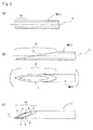
- the metallic material BM is rotated reciprocally by a required angle with the axial center C as a rotation center and then both left and right sides of a tip side of the primary inclined surface 2 are obliquely cut further (see Figure 3(c) ).
- a tip part to be the blade tip 3 is formed, secondary inclined surfaces 4, 4 are formed on the left and right of an adjacent rear part thereof, and a remaining primary inclined surface 2' is formed further at an adjacent rear part thereof. Also, edge parts at the outer part of the left and right secondary inclined surfaces 4, 4 and the remaining primary inclined surface 2' are formed as the blade parts 5, 5. Also, at a boundary part of the secondary inclined surfaces 4, 4 and the remaining primary inclined surface 2', linear swollen parts 6, 6 due to inclination angles in the two cutting processes are generated.
- a shape of the distal end part 1A of the injection needle 1 is roughly completed, and the left and right secondary inclined surfaces 4, 4 and the remaining primary inclined surface 2' are mechanically polished thereafter.
- the blade tip 3 and the blade parts 5, 5 are polished by the mechanical polishing, however, fine burrs from the mechanical polishing are generated at the parts (not shown in the figure).
- the entire distal end part 1A including the blade tip 3 and the blade part 5 is immersed in an electrolytic solution and the distal end part 1A is electrolytically polished.
- the injection needle 1 of the present embodiment composed of the alloy containing cobalt and molybdenum has a problem that, when the time of electrolytic polishing is too long, the blade tip 3 becomes round even though the burrs at the blade parts 5, 5 are removed. Then, in the present embodiment, as the time of electrolytically polishing the distal end part 1A, the time for removing the burrs from the blade tip 3 and the blade parts 5, 5 and achieving smooth finish is set. Thus, the fine burrs generated during the mechanical polishing in the previous process are removed from the blade tip 3 and the blade part 5 and final polishing is carried out to the parts.
- the blade tip 3 and the blade part 5 are formed at the distal end part 1A in such a manner, and the manufacturing process of the injection needle 1 of the present embodiment is ended.
- a method of cutting the distal end part of the material BM illustrated in Figure 3(b)- Figure 3(c) is conventionally and generally called "lancet cut".
- the above-described manufacturing process of the injection needle 1 of the present embodiment itself is the same as the conventional well-known manufacturing process, and a configuration of the distal end part 1A to which the lancet cut is carried out is also well-known (see Figure 7 in Patent Literature 1).
- the injection needle 1 of the present embodiment is composed of the alloy containing cobalt and molybdenum, and the composition of the alloy is illustrated in an upper stage of Figure 4 . That is, the composition of the injection needle 1 of the present embodiment is constituted of the alloy formed of 38.62 mass% cobalt, 20.987 mass% chrome, 14.37 mass% iron, 14.29 mass% nickel, 7.43 mass% molybdenum, and the balance being the other elements.
- the material of the injection needle 1 is the alloy containing cobalt and molybdenum, with cobalt being a main component.
- a composition ratio of the respective elements is, preferably, 39.00-42.00 mass% cobalt, 18.00-21.50 mass% chrome, 14.00-18.00 mass% nickel, and 6.50-8.00 mass% molybdenum.
- For numerical values of the composition ratio of the respective elements described in Figure 4 average values of measured values at two or more parts in the injection needle 1 are described.
- a lower stage of Figure 4 illustrates a composition of the injection needle 1 made of stainless steel, that is manufactured from a thin plate composed of an alloy of a conventional composition through the manufacturing process completely same as the present embodiment. That is, the composition of the conventional injection needle 1 is constituted of the alloy formed of 69.2 mass% iron, 19.49 mass% chrome, 8.81 mass% nickel, and the balance being the other elements. In other words, the material of the conventional injection needle 1 is the stainless steel with iron as a main component.
- the composition ratio of the respective elements described in Figure 4 an average value of measured values at two or more parts in the injection needle 1 which is a conventional product is described.
- the inventor of the present application prepared three each of samples having the same outer diameter D and the same total length as test pieces, and conducted various kinds of tests to three each of the injection needles 1 of the present embodiment and the conventional product. Specific dimensions of respective parts are illustrated in Figure 5 . Also, as illustrated in Figure 2 , reference character D denotes an outer diameter, and reference character d1 denotes an inner diameter. Reference character L1 denotes an axial direction dimension of the distal end part 1A, reference character L2 denotes a shortest dimension from the blade tip 3 to the swollen part 6, and reference character L3 denotes an axial direction dimension from the swollen part 6 to the rearmost part of the distal end part 1A. Further, a blade surface angle indicates the respective inclination angles in the first process and the second process in the above-described lancet cut, and a rotation angle indicates the rotation angle of rotating the metallic material in the second process.
- Figure 6 illustrates a measurement result regarding surface roughness of the injection needle 1 of the present embodiment and the conventional product.
- the measurement result indicates the average value of the measured values measured for three each of the samples of the injection needle 1 of the present embodiment and the conventional product.
- a numerical value of the injection needle 1 of the present embodiment is clearly smaller than that of the conventional product, and it is understood that the inner peripheral surface of the present embodiment is smoother than that of the conventional product.
- the difference in the roughness of the inner peripheral surface also appears as difference in a liquid flow rate of liquid distributed on an inner surface of the injection needle 1. That is, the time during which water is distributed inside the injection needle 1 is measured in Figure 7 . In this experiment, the time during which 1g of water flows inside the injection needle 1 at 50.0 kPa is indicated.
- Figure 7 also illustrates the average value of results of conducting the test for three each of the injection needle 1 of the present embodiment and the conventional product. As illustrated in Figure 7 , while it is 2.547 seconds for the injection needle 1 of the present embodiment, it is 3.413 seconds for the conventional product, and it is clear that the liquid flow rate of the present embodiment is higher than that of the conventional product.
- the channel resistance is smaller in the present embodiment than in the conventional product. It is considered to be due to the difference in the roughness of the inner peripheral surface described above. In such a manner, according to the present embodiment, the injection needle 1 having the channel resistance smaller than that of the conventional product even with the same outer diameter as the conventional product can be provided.
- Figure 8 illustrates a result of measuring difference in hardness and rigidity regarding the injection needle 1 of the present embodiment and the conventional product.
- Figure 8 also illustrates the average value of measurement results for three each of the injection needle 1 of the present embodiment and the conventional product.
- the rigidity is measured as follows. That is, a deflection amount of the blade tip 3 when a load is applied to a part 10 mm behind the blade tip 3 is measured. While the deflection amount is 0.2586 mm in the present embodiment, it is 0.3548 mm in the conventional product. That is, it is clear that the rigidity is higher in the present embodiment than in the conventional product.
- the present invention can provide the injection needle 1 for which easiness of breaking that is a conventional problem in the injection needle with a small diameter is improved.
- the injection needle 1 of the present embodiment is excellent in the hardness and the rigidity, the outer diameter of the injection needle 1 that is limited by an ISO standard can be extremely reduced. Therefore, the injection needle 1 of the present embodiment can reduce a generation rate of ISO nonconforming products, that rises accompanying the extreme reduction of the outer diameter. Also, since the outer diameter is small, the probability that the injection needle 1 is brought into contact with a pain acceptor when an injection is given to a patient can be reduced.
- the injection needle 1 of the present embodiment can be thinner than before (see Figure 5 , for instance), even when the outer diameter is the same as the conventional product, the injection needle 1 having the inner diameter larger than the conventional product can be manufactured. In this way, since the injection needle 1 with the large inner diameter can be provided, a flow rate of a liquid chemical distributed inside the injection needle 1 is increased and the injection needle 1 is not easily clogged with the liquid chemical. Also, inner pressure increase when administering the liquid chemical can be suppressed. Therefore, the injection needle 1 of the present embodiment is suitable when administering a hormone drug that tends to be crystallized by a pressure.
- use of the technology of the present invention can achieve an ultrafine diameter (the outer diameter being 0.185 mm to 0.200 mm, the thickness being 0.035 mm to 0.037 mm, and the inner diameter being 0.115 mm to 0.126 mm) that is difficult to be implemented by a conventional method using SUS.
- the burrs at the blade tip 3 and the blade part 5 are completely removed after the electrolytic polishing that is the last process, and the secondary inclined surfaces 4, 4 and the remaining primary inclined surface 2' are also finished to be smooth surfaces. Also, the swollen parts 6, 6 are rounded and a cross section thereof becomes a smooth circular arc shape. That is, it is clear when the present embodiment and the conventional product are compared by the enlarged photos in Figure 9- Figure 12 .
- the present embodiment is the injection needle 1 composed of the alloy containing cobalt and molybdenum, the distal end part 1A including the blade tip 3 and the blade parts 5, 5 is extremely smoothly finished after the electrolytic polishing. Then, in the electrolytic polishing, since electric resistance is small because the injection needle 1 contains cobalt, processing time of the electrolytic polishing can be made shorter than before.
- the present embodiment can reduce pains when puncturing the injection needle 1 into a patient compared to the conventional product.
Landscapes
- Health & Medical Sciences (AREA)
- Animal Behavior & Ethology (AREA)
- Vascular Medicine (AREA)
- Veterinary Medicine (AREA)
- Public Health (AREA)
- Heart & Thoracic Surgery (AREA)
- General Health & Medical Sciences (AREA)
- Life Sciences & Earth Sciences (AREA)
- Biomedical Technology (AREA)
- Hematology (AREA)
- Anesthesiology (AREA)
- Engineering & Computer Science (AREA)
- Surgery (AREA)
- Epidemiology (AREA)
- Chemical & Material Sciences (AREA)
- Inorganic Chemistry (AREA)
- Infusion, Injection, And Reservoir Apparatuses (AREA)
Abstract
Description
- The present invention relates to an injection needle, and, more specifically relates to an injection needle composed of an alloy containing cobalt and molybdenum.
- Conventionally, an improvement plan for reducing implement resistance and channel resistance in a metallic injection needle is proposed (for instance, Patent Literature 1). That is, the
Patent Literature 1 discloses an injection needle including a tapered part between an impalement part to be a blade tip and a large-diameter base part. - Patent Literature 1: Japanese Patent Laid-Open No.
2008-200528 - Since conventional injection needles including the one in
Patent Literature 1 are made of stainless steel, there is a problem that a surface of an inner peripheral surface of the injection needle becomes rough and channel resistance increases because of that. Also, in the injection needle made of stainless steel, when an outer diameter thereof is to be reduced, a distal end part tends to be broken or damaged so that there is a limit in reduction of the outer diameter for reducing implement resistance. - In consideration of the above-described circumstances, in the present invention, in an injection needle made of a metal with a blade tip and a blade part formed at a distal end part, the metal is an alloy containing cobalt and molybdenum.
- Such a configuration can provide an injection needle for which surface roughness of an inner peripheral surface of the injection needle is low and smooth compared to conventional products, as is clear from results of tests and measurement described later.
-
- [
Figure 1] Figure 1 is a plan view of a main section illustrating one embodiment of the present invention. - [
Figure 2] Figure 2 is a side view from a direction of an arrow II inFigure 1 . - [
Figure 3] Figure 3 is a manufacturing process diagram of an injection needle of the present embodiment illustrated inFigure 1 ,Figure 3(a) illustrates a process of molding a metallic material,Figure 3(b) illustrates a first process of lancet cut, andFigure 3(c) illustrates a second process of the lancet cut. - [
Figure 4] Figure 4 is a diagram illustrating compositions of elements of the injection needle of the present embodiment illustrated inFigure 1 and a conventional product. - [
Figure 5] Figure 5 is a diagram illustrating dimensions of respective parts of the injection needle of the present embodiment illustrated inFigure 1 and a conventional product. - [
Figure 6] Figure 6 is a diagram illustrating a test result of a surface roughness test conducted to the injection needle of the present embodiment illustrated inFigure 1 and a conventional product. - [
Figure 7] Figure 7 is a diagram illustrating a test result of a liquid flow rate test conducted to the injection needle of the present embodiment illustrated inFigure 1 and a conventional product. - [
Figure 8] Figure 8 is a diagram illustrating a test result of a hardness/rigidity test conducted to the injection needle of the present embodiment illustrated inFigure 1 and a conventional product. - [
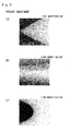
Figure 9] Figure 9 is an enlarged photo (backscattered electron image of ×150 magnification) of a distal end part in the injection needle of the present embodiment illustrated inFigure 1 ,Figure 9(a) illustrates the most distal end part (blade tip),Figure 9(b) illustrates a center part, andFigure 9(c) illustrates a rearmost part. - [
Figure 10] Figure 10 is an enlarged photo (backscattered electron image of ×150 magnification) of a distal end part in the injection needle which is a conventional product,Figure 10(a) illustrates the most distal end part (blade tip),Figure 10(b) illustrates a center part, andFigure 12(c) illustrates a rearmost part. - [
Figure 11] Figure 11 is an enlarged photo (backscattered electron image of ×500 magnification) of a distal end part in the injection needle of the present embodiment illustrated inFigure 1 ,Figure 11(a) illustrates the most distal end part (blade tip),Figure 11(b) illustrates a center part, and Figure 13(c) illustrates a rearmost part. - [
Figure 12] Figure 12 is an enlarged photo (backscattered electron image of ×500 magnification) of a distal end part in the injection needle which is a conventional product,Figure 12(a) illustrates the most distal end part (blade tip),Figure 12(b) illustrates a center part, andFigure 12(c) illustrates a rearmost part. - [
Figure 13] Figure 13 is an enlarged photo (backscattered electron image of ×1000 magnification) of an inner peripheral surface in the injection needle of the present embodiment illustrated inFigure 1 . - [
Figure 14] Figure 14 is an enlarged photo (backscattered electron image of ×1000 magnification) of an inner peripheral surface in the injection needle which is a conventional product. - Hereinafter, describing the present invention for an illustrated embodiment, in
Figure 1 and Figure 2 ,reference numeral 1 denotes an injection needle made of a metal, and ablade tip 3 and ablade part 5 and the like are formed at adistal end part 1A of theinjection needle 1 through a manufacturing process of lancet cut or the like similarly to a conventional product. While a composition of a material will be described later in detail, theinjection needle 1 of the present embodiment is characterized in that an alloy containing cobalt and molybdenum is used as the material (metallic material). - Here, the manufacturing process of the
injection needle 1 of the present embodiment will be described withFigure 3 . That is, first, a thin plate composed of the alloy containing cobalt and molybdenum is molded into a cylindrical shape and a metallic material BM in a thin and long cylindrical shape is produced (seeFigure 3(a) ). Then, thedistal end part 1A of the metallic material BM is cut obliquely at a required angle to an axial center C (seeFigure 3(a)-Figure 3(b) ). Thus, a loop-like primaryinclined surface 2 is formed at thedistal end part 1A (seeFigure 3(b) ). Thereafter, the metallic material BM is rotated reciprocally by a required angle with the axial center C as a rotation center and then both left and right sides of a tip side of the primaryinclined surface 2 are obliquely cut further (seeFigure 3(c) ). - Thus, a tip part to be the
blade tip 3 is formed, secondaryinclined surfaces inclined surfaces blade parts inclined surfaces swollen parts - Thus, a shape of the
distal end part 1A of theinjection needle 1 is roughly completed, and the left and right secondaryinclined surfaces blade tip 3 and theblade parts distal end part 1A including theblade tip 3 and theblade part 5 is immersed in an electrolytic solution and thedistal end part 1A is electrolytically polished. Here, theinjection needle 1 of the present embodiment composed of the alloy containing cobalt and molybdenum has a problem that, when the time of electrolytic polishing is too long, theblade tip 3 becomes round even though the burrs at theblade parts distal end part 1A, the time for removing the burrs from theblade tip 3 and theblade parts blade tip 3 and theblade part 5 and final polishing is carried out to the parts. - The
blade tip 3 and theblade part 5 are formed at thedistal end part 1A in such a manner, and the manufacturing process of theinjection needle 1 of the present embodiment is ended. A method of cutting the distal end part of the material BM illustrated inFigure 3(b)-Figure 3(c) is conventionally and generally called "lancet cut". The above-described manufacturing process of theinjection needle 1 of the present embodiment itself is the same as the conventional well-known manufacturing process, and a configuration of thedistal end part 1A to which the lancet cut is carried out is also well-known (seeFigure 7 in Patent Literature 1). - As described above, the
injection needle 1 of the present embodiment is composed of the alloy containing cobalt and molybdenum, and the composition of the alloy is illustrated in an upper stage ofFigure 4 . That is, the composition of theinjection needle 1 of the present embodiment is constituted of the alloy formed of 38.62 mass% cobalt, 20.987 mass% chrome, 14.37 mass% iron, 14.29 mass% nickel, 7.43 mass% molybdenum, and the balance being the other elements. In other words, the material of theinjection needle 1 is the alloy containing cobalt and molybdenum, with cobalt being a main component. A composition ratio of the respective elements is, preferably, 39.00-42.00 mass% cobalt, 18.00-21.50 mass% chrome, 14.00-18.00 mass% nickel, and 6.50-8.00 mass% molybdenum. For numerical values of the composition ratio of the respective elements described inFigure 4 , average values of measured values at two or more parts in theinjection needle 1 are described. - In the meantime, a lower stage of
Figure 4 illustrates a composition of theinjection needle 1 made of stainless steel, that is manufactured from a thin plate composed of an alloy of a conventional composition through the manufacturing process completely same as the present embodiment. That is, the composition of theconventional injection needle 1 is constituted of the alloy formed of 69.2 mass% iron, 19.49 mass% chrome, 8.81 mass% nickel, and the balance being the other elements. In other words, the material of theconventional injection needle 1 is the stainless steel with iron as a main component. For numerical values of the composition ratio of the respective elements described inFigure 4 , an average value of measured values at two or more parts in theinjection needle 1 which is a conventional product is described. - When an inventor of the present application carried out various kinds of tests and measurements for required items regarding the
injection needle 1 of the present embodiment and theinjection needle 1 of the conventional product, that are formed of the compositions illustrated inFigure 4 , it was clarified that channel resistance is smaller in theinjection needle 1 of the present embodiment, that is formed of the alloy containing cobalt and molybdenum, than in theconventional injection needle 1 made of stainless steel, or the like. - In order to test the
injection needle 1 of the present embodiment and the conventional product, the inventor of the present application prepared three each of samples having the same outer diameter D and the same total length as test pieces, and conducted various kinds of tests to three each of theinjection needles 1 of the present embodiment and the conventional product. Specific dimensions of respective parts are illustrated inFigure 5 . Also, as illustrated inFigure 2 , reference character D denotes an outer diameter, and reference character d1 denotes an inner diameter. Reference character L1 denotes an axial direction dimension of thedistal end part 1A, reference character L2 denotes a shortest dimension from theblade tip 3 to theswollen part 6, and reference character L3 denotes an axial direction dimension from theswollen part 6 to the rearmost part of thedistal end part 1A. Further, a blade surface angle indicates the respective inclination angles in the first process and the second process in the above-described lancet cut, and a rotation angle indicates the rotation angle of rotating the metallic material in the second process. - First,
Figure 6 illustrates a measurement result regarding surface roughness of theinjection needle 1 of the present embodiment and the conventional product. The measurement result indicates the average value of the measured values measured for three each of the samples of theinjection needle 1 of the present embodiment and the conventional product. For the surface roughness of an outer peripheral surface of theinjection needle 1, there is not a big difference between theinjection needle 1 of the present embodiment and the conventional product. However, for the surface roughness of an inner peripheral surface, a numerical value of theinjection needle 1 of the present embodiment is clearly smaller than that of the conventional product, and it is understood that the inner peripheral surface of the present embodiment is smoother than that of the conventional product. - That fact is clear from enlarged photos comparing the distal end part and the inner peripheral surface of the
injection needle 1, that are illustrated inFigure 9-Figure 14 . While fine wrinkles are seen only partially on the inner peripheral surface of theinjection needle 1 of the present embodiment as illustrated inFigure 9(a) ,Figure 11(a) andFigure 13 , fine wrinkles are seen over the entire inner peripheral surface of theinjection needle 1 of the conventional product as illustrated inFigure 10(a) ,Figure 12(a) andFigure 14 . - It is considered that difference in roughness is generated between the inner peripheral surface of the
injection needle 1 of the present embodiment and the inner peripheral surface of the conventional product in such a manner due to difference in the material of theinjection needle 1. That is, since theinjection needle 1 of the present embodiment is the alloy containing cobalt and molybdenum, wrinkles are hardly generated on the inner peripheral surface when the metallic material BM in a thin plate shape is molded into the thin and long cylindrical shape in the above-described manufacturing process. On the other hand, in the conventional product made of stainless steel, wrinkles are easily generated on the entire inner peripheral surface when stainless steel in the thin plate shape is molded into the cylindrical shape. Therefore, in comparison as finished products after being manufactured, roughness of the inner peripheral surface is lower and smoother in theinjection needle 1 of the present embodiment than in the conventional product. - The difference in the roughness of the inner peripheral surface also appears as difference in a liquid flow rate of liquid distributed on an inner surface of the
injection needle 1. That is, the time during which water is distributed inside theinjection needle 1 is measured inFigure 7 . In this experiment, the time during which 1g of water flows inside theinjection needle 1 at 50.0 kPa is indicated.Figure 7 also illustrates the average value of results of conducting the test for three each of theinjection needle 1 of the present embodiment and the conventional product. As illustrated inFigure 7 , while it is 2.547 seconds for theinjection needle 1 of the present embodiment, it is 3.413 seconds for the conventional product, and it is clear that the liquid flow rate of the present embodiment is higher than that of the conventional product. In other words, it is clear that the channel resistance is smaller in the present embodiment than in the conventional product. It is considered to be due to the difference in the roughness of the inner peripheral surface described above. In such a manner, according to the present embodiment, theinjection needle 1 having the channel resistance smaller than that of the conventional product even with the same outer diameter as the conventional product can be provided. - Next,
Figure 8 illustrates a result of measuring difference in hardness and rigidity regarding theinjection needle 1 of the present embodiment and the conventional product.Figure 8 also illustrates the average value of measurement results for three each of theinjection needle 1 of the present embodiment and the conventional product. - For the hardness, while it is 526.0 (Hv) in the present embodiment, it is 424.7 (Hv) in the conventional product. Clearly, the hardness is higher in the
injection needle 1 of the present embodiment than in the conventional product. - The rigidity is measured as follows. That is, a deflection amount of the
blade tip 3 when a load is applied to apart 10 mm behind theblade tip 3 is measured. While the deflection amount is 0.2586 mm in the present embodiment, it is 0.3548 mm in the conventional product. That is, it is clear that the rigidity is higher in the present embodiment than in the conventional product. - In this way, since the hardness and the rigidity are higher in the
injection needle 1 of the present embodiment composed of the alloy containing cobalt and molybdenum than in the conventional product, the injection needle which is harder to break than the conventional product can be achieved. Therefore, the present invention can provide theinjection needle 1 for which easiness of breaking that is a conventional problem in the injection needle with a small diameter is improved. - Also, since the
injection needle 1 of the present embodiment is excellent in the hardness and the rigidity, the outer diameter of theinjection needle 1 that is limited by an ISO standard can be extremely reduced. Therefore, theinjection needle 1 of the present embodiment can reduce a generation rate of ISO nonconforming products, that rises accompanying the extreme reduction of the outer diameter. Also, since the outer diameter is small, the probability that theinjection needle 1 is brought into contact with a pain acceptor when an injection is given to a patient can be reduced. - Further, since the
injection needle 1 of the present embodiment can be thinner than before (seeFigure 5 , for instance), even when the outer diameter is the same as the conventional product, theinjection needle 1 having the inner diameter larger than the conventional product can be manufactured. In this way, since theinjection needle 1 with the large inner diameter can be provided, a flow rate of a liquid chemical distributed inside theinjection needle 1 is increased and theinjection needle 1 is not easily clogged with the liquid chemical. Also, inner pressure increase when administering the liquid chemical can be suppressed. Therefore, theinjection needle 1 of the present embodiment is suitable when administering a hormone drug that tends to be crystallized by a pressure. - Also, use of the technology of the present invention can achieve an ultrafine diameter (the outer diameter being 0.185 mm to 0.200 mm, the thickness being 0.035 mm to 0.037 mm, and the inner diameter being 0.115 mm to 0.126 mm) that is difficult to be implemented by a conventional method using SUS.
- Further, for the
injection needle 1 of the present embodiment, the burrs at theblade tip 3 and theblade part 5 are completely removed after the electrolytic polishing that is the last process, and the secondaryinclined surfaces swollen parts Figure 9-Figure 12 . That is, as illustrated inFigure 9(a)-Figure 9(b) andFigure 11(a)-Figure 11(c) , in the present embodiment, theblade tip 3 is turned to a state of being pointed at an acute angle, and theblade part 5 and the secondaryinclined surfaces swollen parts inclined surfaces Figure 10(a)-Figure 10(b) andFigure 12(a)-Figure 12(c) , in the conventional product, though theblade tip 3 is turned to the acute angle, fine recesses and projections (burrs) remain at theblade parts inclined surfaces swollen parts inclined surfaces - As described above, since the present embodiment is the
injection needle 1 composed of the alloy containing cobalt and molybdenum, thedistal end part 1A including theblade tip 3 and theblade parts injection needle 1 contains cobalt, processing time of the electrolytic polishing can be made shorter than before. - In this way, since the
blade tip 3, theblade part 5 and theswollen parts injection needle 1 of the present embodiment, it is possible to reduce puncture resistance when puncturing thedistal end part 1A of theinjection needle 1 into a patient. Therefore, the present embodiment can reduce pains when puncturing theinjection needle 1 into a patient compared to the conventional product. - While the embodiment describes the case of applying the present invention to the
injection needle 1 to which the lancet cut is carried out, it is needless to say that the present invention is applicable to the other metallic injection needles to which the lancet cut is not carried out. -
- 1
- Injection needle
- 1A
- Distal end part
- 3
- Blade tip
- 5, 5
- Blade part
Claims (5)
- An injection needle made of a metal with a blade tip and a blade part formed at a distal end part, wherein
the metal is an alloy containing cobalt and molybdenum. - The injection needle according to claim 1, wherein the alloy contains 39.00-42.00 mass% cobalt and 6.50-8.00 mass% molybdenum.
- The injection needle according to claim 1 or claim 2, wherein the alloy contains chrome, iron, and nickel.
- The injection needle according to claim 1, wherein the alloy contains 39.00-42.00 mass% cobalt, 6.50-8.00 mass% molybdenum, 18.00-21.50 mass% chrome, 14.00-18.00 mass% nickel, and 6.50-8.00 mass% molybdenum.
- The injection needle according to any one of claims 1 to 4, wherein the blade tip and the blade part at the distal end part are finally polished to be smooth by electrolytic polishing.
Applications Claiming Priority (2)
| Application Number | Priority Date | Filing Date | Title |
|---|---|---|---|
| JP2011242294 | 2011-11-04 | ||
| PCT/JP2012/078443 WO2013065814A1 (en) | 2011-11-04 | 2012-11-02 | Injection needle |
Publications (2)
| Publication Number | Publication Date |
|---|---|
| EP2774643A1 true EP2774643A1 (en) | 2014-09-10 |
| EP2774643A4 EP2774643A4 (en) | 2015-06-03 |
Family
ID=48192151
Family Applications (1)
| Application Number | Title | Priority Date | Filing Date |
|---|---|---|---|
| EP12846777.6A Withdrawn EP2774643A4 (en) | 2011-11-04 | 2012-11-02 | Injection needle |
Country Status (4)
| Country | Link |
|---|---|
| US (2) | US20140296797A1 (en) |
| EP (1) | EP2774643A4 (en) |
| JP (2) | JP6073016B2 (en) |
| WO (1) | WO2013065814A1 (en) |
Cited By (1)
| Publication number | Priority date | Publication date | Assignee | Title |
|---|---|---|---|---|
| WO2021033060A1 (en) * | 2019-08-16 | 2021-02-25 | Blazko Anton | Tool with ground edge, mainly cannula or lancet, method of its production and device for its production |
Families Citing this family (9)
| Publication number | Priority date | Publication date | Assignee | Title |
|---|---|---|---|---|
| EP3064240B1 (en) * | 2013-11-03 | 2020-11-25 | Terumo Kabushiki Kaisha | Needle-equipped sysringe, pre-filled syringe, and medical liquid administration device using same |
| WO2016006342A1 (en) * | 2014-07-08 | 2016-01-14 | テルモ株式会社 | Injection needle |
| WO2016094620A1 (en) * | 2014-12-11 | 2016-06-16 | Facet Technologies, Llc | Needle with multi-bevel tip geometry |
| JP6625566B2 (en) * | 2015-01-20 | 2019-12-25 | テルモ株式会社 | Injection needle assembly and syringe for injecting a drug solution into the upper layer of skin having the same |
| JP2018143630A (en) * | 2017-03-08 | 2018-09-20 | テルモ株式会社 | Puncture needle |
| JP6596470B2 (en) * | 2017-07-20 | 2019-10-23 | トクセン工業株式会社 | Medical treatment device wire and guide wire |
| JP6940053B2 (en) * | 2018-01-26 | 2021-09-22 | 住友電工ファインポリマー株式会社 | Medical needle |
| USD1023297S1 (en) * | 2018-06-04 | 2024-04-16 | Airlift Concrete Experts, LLC | Subterranean injection rod tip |
| WO2025009225A1 (en) * | 2023-07-06 | 2025-01-09 | テルモ株式会社 | Puncture needle |
Family Cites Families (25)
| Publication number | Priority date | Publication date | Assignee | Title |
|---|---|---|---|---|
| US3767385A (en) * | 1971-08-24 | 1973-10-23 | Standard Pressed Steel Co | Cobalt-base alloys |
| US3816920A (en) * | 1972-11-30 | 1974-06-18 | Gillette Co | Novel cutting edges and processes for making them |
| US4384942A (en) * | 1980-09-08 | 1983-05-24 | Lifeline Products, Inc. | Cannulae grinding method and machine |
| EP0325426A1 (en) * | 1988-01-19 | 1989-07-26 | Robert Burnham Lufkin | Magnetic resonance needle |
| US5258013A (en) * | 1991-01-07 | 1993-11-02 | United States Surgical Corporation | Siliconized surgical needle and method for its manufacture |
| US5607407A (en) * | 1994-05-09 | 1997-03-04 | Tolkoff; Marc J. | Catheter assembly |
| US8257725B2 (en) * | 1997-09-26 | 2012-09-04 | Abbott Laboratories | Delivery of highly lipophilic agents via medical devices |
| US6537242B1 (en) * | 2000-06-06 | 2003-03-25 | Becton, Dickinson And Company | Method and apparatus for enhancing penetration of a member for the intradermal sampling or administration of a substance |
| JP4083425B2 (en) * | 2001-01-25 | 2008-04-30 | テルモ株式会社 | Liquid injection needle and liquid injection device |
| JP2003062747A (en) * | 2001-08-23 | 2003-03-05 | Japan Science & Technology Corp | Processing method and apparatus using magnetic fluid |
| JP2003136142A (en) * | 2001-10-31 | 2003-05-14 | Terumo Corp | Metallic tubular member and method for manufacturing metallic tubular member |
| US8277411B2 (en) * | 2002-01-31 | 2012-10-02 | Boston Scientific Scimed, Inc. | Needle device |
| JP4025567B2 (en) * | 2002-03-29 | 2007-12-19 | テルモ株式会社 | Needle |
| JP5148107B2 (en) * | 2003-01-21 | 2013-02-20 | カルメル ファルマ アクチボラゲット | Needle for piercing the membrane |
| JP4592061B2 (en) * | 2003-06-10 | 2010-12-01 | 三菱鉛筆株式会社 | Injection needle, injection needle manufacturing method, and injection needle manufacturing apparatus |
| US7076987B2 (en) * | 2004-08-05 | 2006-07-18 | Becton, Dickinson And Company | Method of producing tapered or pointed cannula |
| JP4826711B2 (en) * | 2005-03-31 | 2011-11-30 | ニプロ株式会社 | Needle |
| US20090209923A1 (en) * | 2005-04-19 | 2009-08-20 | Linderoth Soeren | Disposable hypodermic needle |
| US7842008B2 (en) * | 2005-11-21 | 2010-11-30 | Becton, Dickinson And Company | Intradermal delivery device |
| JP2007181638A (en) * | 2006-01-04 | 2007-07-19 | Iguchi Atsuko | Ceramic-coated puncture needle giving smaller pains when piercing into the skin and presenting clear ultrasonic images, as well as method of manufacturing the same |
| JP4473234B2 (en) * | 2006-06-22 | 2010-06-02 | テルモ株式会社 | Metal tubular body and manufacturing method thereof |
| US20080215017A1 (en) * | 2007-02-07 | 2008-09-04 | Vladimir Gergely | Method of making cobalt-based alloy tubes having enhanced mechanical performance characteristics and a tube formed by the method |
| US20110112575A1 (en) * | 2008-04-30 | 2011-05-12 | Mani, Inc. | Medical Suture Needle |
| JP2008200528A (en) | 2008-05-28 | 2008-09-04 | Terumo Corp | Injection needle |
| US8735354B2 (en) * | 2008-11-07 | 2014-05-27 | Uab Research Foundation | Endothelium mimicking nanomatrix |
-
2012
- 2012-11-02 WO PCT/JP2012/078443 patent/WO2013065814A1/en not_active Ceased
- 2012-11-02 JP JP2013541857A patent/JP6073016B2/en active Active
- 2012-11-02 US US14/353,709 patent/US20140296797A1/en not_active Abandoned
- 2012-11-02 EP EP12846777.6A patent/EP2774643A4/en not_active Withdrawn
-
2016
- 2016-04-14 US US15/099,064 patent/US20160303332A1/en not_active Abandoned
- 2016-12-28 JP JP2016254983A patent/JP2017056289A/en active Pending
Cited By (1)
| Publication number | Priority date | Publication date | Assignee | Title |
|---|---|---|---|---|
| WO2021033060A1 (en) * | 2019-08-16 | 2021-02-25 | Blazko Anton | Tool with ground edge, mainly cannula or lancet, method of its production and device for its production |
Also Published As
| Publication number | Publication date |
|---|---|
| WO2013065814A1 (en) | 2013-05-10 |
| JPWO2013065814A1 (en) | 2015-04-02 |
| US20160303332A1 (en) | 2016-10-20 |
| JP2017056289A (en) | 2017-03-23 |
| JP6073016B2 (en) | 2017-02-01 |
| US20140296797A1 (en) | 2014-10-02 |
| EP2774643A4 (en) | 2015-06-03 |
Similar Documents
| Publication | Publication Date | Title |
|---|---|---|
| US20140296797A1 (en) | Injection needle | |
| US7435239B2 (en) | Injection needle with needle point offset from central plane | |
| JP2007289664A (en) | Injection needle manufacturing method and injection needle | |
| US20180043419A1 (en) | Medical suture needle | |
| EP1634535A1 (en) | Medical needle and cutting tool | |
| US10350715B2 (en) | Method of producing a medical cutting instrument | |
| JP2003320430A (en) | Metallic tubular body and its manufacturing method | |
| US20060185169A1 (en) | Methods for manufacturing endodontic instruments | |
| CN102481151A (en) | Medical suture needle | |
| JP2009233028A (en) | Medical hollow needle and guide wire insertion system | |
| US20170252037A1 (en) | Suture needle | |
| WO2023176645A1 (en) | Puncture needle | |
| JP2017080117A (en) | Medical puncture needle | |
| EP1991140A1 (en) | Method for producing disposable tweezer tips for microsurgery tweezers and microsurgery tweezers provided with such tips | |
| US10245060B2 (en) | Edged medical cutting tool | |
| JP4051010B2 (en) | Medical hollow needle and method for producing the same | |
| CN204542317U (en) | A kind of trocar puncture needle | |
| WO1999004843A1 (en) | Mandrin of medical anesthetic needle and method of manufacturing same | |
| CN108472033A (en) | Medical suture needle | |
| CN111132617B (en) | Cap parts, plug bodies and blood collection containers | |
| EP4112106A1 (en) | Medical puncturing needle | |
| US11524125B2 (en) | Puncture needle | |
| CN109069761B (en) | Method for manufacturing needle cannula with reduced end portion by electrochemical etching | |
| JP2018072307A (en) | Sampling nozzle and manufacturing method therefor | |
| JP2007038021A (en) | Metal injection needle |
Legal Events
| Date | Code | Title | Description |
|---|---|---|---|
| PUAI | Public reference made under article 153(3) epc to a published international application that has entered the european phase |
Free format text: ORIGINAL CODE: 0009012 |
|
| 17P | Request for examination filed |
Effective date: 20140514 |
|
| AK | Designated contracting states |
Kind code of ref document: A1 Designated state(s): AL AT BE BG CH CY CZ DE DK EE ES FI FR GB GR HR HU IE IS IT LI LT LU LV MC MK MT NL NO PL PT RO RS SE SI SK SM TR |
|
| DAX | Request for extension of the european patent (deleted) | ||
| RA4 | Supplementary search report drawn up and despatched (corrected) |
Effective date: 20150506 |
|
| RIC1 | Information provided on ipc code assigned before grant |
Ipc: A61M 5/158 20060101ALI20150428BHEP Ipc: A61M 5/32 20060101AFI20150428BHEP |
|
| 17Q | First examination report despatched |
Effective date: 20160203 |
|
| GRAP | Despatch of communication of intention to grant a patent |
Free format text: ORIGINAL CODE: EPIDOSNIGR1 |
|
| INTG | Intention to grant announced |
Effective date: 20160809 |
|
| STAA | Information on the status of an ep patent application or granted ep patent |
Free format text: STATUS: THE APPLICATION IS DEEMED TO BE WITHDRAWN |
|
| 18D | Application deemed to be withdrawn |
Effective date: 20161220 |