EP2774223B1 - Electrical contact having rhombic knurl pattern - Google Patents
Electrical contact having rhombic knurl pattern Download PDFInfo
- Publication number
- EP2774223B1 EP2774223B1 EP12846072.2A EP12846072A EP2774223B1 EP 2774223 B1 EP2774223 B1 EP 2774223B1 EP 12846072 A EP12846072 A EP 12846072A EP 2774223 B1 EP2774223 B1 EP 2774223B1
- Authority
- EP
- European Patent Office
- Prior art keywords
- electrical contact
- lead
- elements
- electrical
- wire cable
- Prior art date
- Legal status (The legal status is an assumption and is not a legal conclusion. Google has not performed a legal analysis and makes no representation as to the accuracy of the status listed.)
- Active
Links
- QNRATNLHPGXHMA-XZHTYLCXSA-N (r)-(6-ethoxyquinolin-4-yl)-[(2s,4s,5r)-5-ethyl-1-azabicyclo[2.2.2]octan-2-yl]methanol;hydrochloride Chemical compound Cl.C([C@H]([C@H](C1)CC)C2)CN1[C@@H]2[C@H](O)C1=CC=NC2=CC=C(OCC)C=C21 QNRATNLHPGXHMA-XZHTYLCXSA-N 0.000 title description 7
- 229910052782 aluminium Inorganic materials 0.000 claims description 19
- XAGFODPZIPBFFR-UHFFFAOYSA-N aluminium Chemical compound [Al] XAGFODPZIPBFFR-UHFFFAOYSA-N 0.000 claims description 19
- IZJSTXINDUKPRP-UHFFFAOYSA-N aluminum lead Chemical compound [Al].[Pb] IZJSTXINDUKPRP-UHFFFAOYSA-N 0.000 claims description 16
- 230000001154 acute effect Effects 0.000 claims description 3
- 229910000838 Al alloy Inorganic materials 0.000 claims description 2
- 239000004020 conductor Substances 0.000 description 19
- PNEYBMLMFCGWSK-UHFFFAOYSA-N Alumina Chemical class [O-2].[O-2].[O-2].[Al+3].[Al+3] PNEYBMLMFCGWSK-UHFFFAOYSA-N 0.000 description 11
- 239000011248 coating agent Substances 0.000 description 8
- 238000000576 coating method Methods 0.000 description 8
- 230000013011 mating Effects 0.000 description 7
- 238000002788 crimping Methods 0.000 description 5
- RYGMFSIKBFXOCR-UHFFFAOYSA-N Copper Chemical compound [Cu] RYGMFSIKBFXOCR-UHFFFAOYSA-N 0.000 description 4
- 230000015572 biosynthetic process Effects 0.000 description 4
- 229910052802 copper Inorganic materials 0.000 description 4
- 239000010949 copper Substances 0.000 description 4
- 238000009413 insulation Methods 0.000 description 4
- 238000000034 method Methods 0.000 description 4
- 230000007935 neutral effect Effects 0.000 description 4
- 239000012530 fluid Substances 0.000 description 3
- 229910052751 metal Inorganic materials 0.000 description 3
- 239000002184 metal Substances 0.000 description 3
- 229910045601 alloy Inorganic materials 0.000 description 2
- 239000000956 alloy Substances 0.000 description 2
- 238000005260 corrosion Methods 0.000 description 2
- 230000007797 corrosion Effects 0.000 description 2
- 239000000463 material Substances 0.000 description 2
- 239000011800 void material Substances 0.000 description 2
- 229910000881 Cu alloy Inorganic materials 0.000 description 1
- 229910000831 Steel Inorganic materials 0.000 description 1
- 230000006978 adaptation Effects 0.000 description 1
- 230000005540 biological transmission Effects 0.000 description 1
- 238000010276 construction Methods 0.000 description 1
- 239000000446 fuel Substances 0.000 description 1
- 238000004519 manufacturing process Methods 0.000 description 1
- 238000012986 modification Methods 0.000 description 1
- 230000004048 modification Effects 0.000 description 1
- 239000011241 protective layer Substances 0.000 description 1
- 230000008054 signal transmission Effects 0.000 description 1
- 238000005507 spraying Methods 0.000 description 1
- 239000010959 steel Substances 0.000 description 1
- 239000000126 substance Substances 0.000 description 1
- 230000007704 transition Effects 0.000 description 1
Images


Classifications
-
- H—ELECTRICITY
- H01—ELECTRIC ELEMENTS
- H01R—ELECTRICALLY-CONDUCTIVE CONNECTIONS; STRUCTURAL ASSOCIATIONS OF A PLURALITY OF MUTUALLY-INSULATED ELECTRICAL CONNECTING ELEMENTS; COUPLING DEVICES; CURRENT COLLECTORS
- H01R4/00—Electrically-conductive connections between two or more conductive members in direct contact, i.e. touching one another; Means for effecting or maintaining such contact; Electrically-conductive connections having two or more spaced connecting locations for conductors and using contact members penetrating insulation
- H01R4/10—Electrically-conductive connections between two or more conductive members in direct contact, i.e. touching one another; Means for effecting or maintaining such contact; Electrically-conductive connections having two or more spaced connecting locations for conductors and using contact members penetrating insulation effected solely by twisting, wrapping, bending, crimping, or other permanent deformation
- H01R4/18—Electrically-conductive connections between two or more conductive members in direct contact, i.e. touching one another; Means for effecting or maintaining such contact; Electrically-conductive connections having two or more spaced connecting locations for conductors and using contact members penetrating insulation effected solely by twisting, wrapping, bending, crimping, or other permanent deformation by crimping
- H01R4/188—Electrically-conductive connections between two or more conductive members in direct contact, i.e. touching one another; Means for effecting or maintaining such contact; Electrically-conductive connections having two or more spaced connecting locations for conductors and using contact members penetrating insulation effected solely by twisting, wrapping, bending, crimping, or other permanent deformation by crimping having an uneven wire-receiving surface to improve the contact
-
- H—ELECTRICITY
- H01—ELECTRIC ELEMENTS
- H01R—ELECTRICALLY-CONDUCTIVE CONNECTIONS; STRUCTURAL ASSOCIATIONS OF A PLURALITY OF MUTUALLY-INSULATED ELECTRICAL CONNECTING ELEMENTS; COUPLING DEVICES; CURRENT COLLECTORS
- H01R4/00—Electrically-conductive connections between two or more conductive members in direct contact, i.e. touching one another; Means for effecting or maintaining such contact; Electrically-conductive connections having two or more spaced connecting locations for conductors and using contact members penetrating insulation
- H01R4/10—Electrically-conductive connections between two or more conductive members in direct contact, i.e. touching one another; Means for effecting or maintaining such contact; Electrically-conductive connections having two or more spaced connecting locations for conductors and using contact members penetrating insulation effected solely by twisting, wrapping, bending, crimping, or other permanent deformation
- H01R4/18—Electrically-conductive connections between two or more conductive members in direct contact, i.e. touching one another; Means for effecting or maintaining such contact; Electrically-conductive connections having two or more spaced connecting locations for conductors and using contact members penetrating insulation effected solely by twisting, wrapping, bending, crimping, or other permanent deformation by crimping
- H01R4/183—Electrically-conductive connections between two or more conductive members in direct contact, i.e. touching one another; Means for effecting or maintaining such contact; Electrically-conductive connections having two or more spaced connecting locations for conductors and using contact members penetrating insulation effected solely by twisting, wrapping, bending, crimping, or other permanent deformation by crimping for cylindrical elongated bodies, e.g. cables having circular cross-section
- H01R4/184—Electrically-conductive connections between two or more conductive members in direct contact, i.e. touching one another; Means for effecting or maintaining such contact; Electrically-conductive connections having two or more spaced connecting locations for conductors and using contact members penetrating insulation effected solely by twisting, wrapping, bending, crimping, or other permanent deformation by crimping for cylindrical elongated bodies, e.g. cables having circular cross-section comprising a U-shaped wire-receiving portion
- H01R4/185—Electrically-conductive connections between two or more conductive members in direct contact, i.e. touching one another; Means for effecting or maintaining such contact; Electrically-conductive connections having two or more spaced connecting locations for conductors and using contact members penetrating insulation effected solely by twisting, wrapping, bending, crimping, or other permanent deformation by crimping for cylindrical elongated bodies, e.g. cables having circular cross-section comprising a U-shaped wire-receiving portion combined with a U-shaped insulation-receiving portion
Definitions
- This invention relates to an electrical contact that includes a knurl pattern, more particularly, the electrical contact includes a knurl pattern having a plurality of recessed elements that contain an axial minor distance defined between a first pair of opposing, generally axial inner corners that is less than a major distance defined between a second pair of opposing inner corners different from the first pair of inner corners.
- Wire conductor/terminal crimps are common in wiring harnesses used in many industries, such as the automotive, trucking, and airline industries. Wiring harnesses provide the conduit for electrical signal transmission that supports the operation of electrical devices in electrical systems in these industries. In the automotive industry, it is increasingly desirable to use lighter weight wire conductors that may assist to provide desired increased fuel economy for a vehicle. These lower mass aluminum wire conductors are often electrically connected to commercially available non-aluminum terminals. The wire conductor is electrically and mechanically connected to the terminal to form the electrical connection. When aluminum wire conductors are used in electrical applications, knurl patterns may assist to break up undesired aluminum oxides formed on the aluminum wire conductor that allow formation of an acceptable electrical connection of the wire conductor to the terminal. Aluminum oxides that are not broken-up when the electrical connection is formed may degrade the performance of the electrical connection such that transmission of an electrical signal through the wire conductor/terminal electrical connection is undesirably degraded or prohibited.
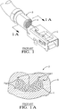
- a conventional knurl pattern contains knurl elements (1) that each have a recessed square pyramid-type shape that may contain voids (2) in the crimp (3) where portions of the aluminum lead (4) do not engage in the square pyramid-type recessions when the lead (4) is crimped to the terminal (5).
- the recessed tips of the square pyramid-type knurl elements point in a direction away from the interior surface of the terminal.
- voids (2) do not contain a portion of lead (4), and thus, cannot electrically connect the aluminum lead (4) with the terminal (5) in the crimp (3).
- Multiple voids prevent achievement of a desired maximum electrical and mechanical connection between the aluminum lead (4) and the terminal (5) as may be the case if, in contrast, the voids were filled with portions of the aluminum lead.
- the surface area of the lead (4) in the local vicinity of the void may also contain aluminum oxides that are not broken up when the wire conductor/terminal electrical connection is formed.
- an electrical contact that overcomes the above mentioned shortcomings and includes a knurl pattern where each element in the knurl pattern has a shape and a shape orientation relative to a wire cable received in to the electrical contact that allows for a more complete break-up of aluminum oxides on a substantial portion of the lead of the wire cable while also providing an improved electrical and mechanical connection between the aluminum wire cable and the electrical contact.
- the invention achieves the solution of the above mentioned problems by implementing an electrical contact according to claim 1.
- an electrical contact includes a knurl pattern disposed along at least a portion of an interior surface of the electrical contact along a length of the electrical contact.
- the portion receives a lead of a wire cable along the axis.
- the knurl pattern includes a plurality of elements that are recessed rhombic elements. Each recessed element has a shape that includes inner corners.
- a first pair of opposing, generally axial inner corners defines an axial minor distance therebetween and a second pair of opposing, inner corners defines a major distance therebetween wherein the axial minor distance is less than the major distance.
- the recessed rhombic elements of the knurl pattern of the electrical contact are especially suitable for engagement with an aluminum wire cable to form the crimp connection.
- a wire assembly that includes the crimp connection is associated with a cable harness disposed in a motorized vehicle.
- the lead is engaged in the knurl pattern in the crimp connection, a more robust electrical and mechanical connection of the wire cable and the electrical contact is attained over a service life of the vehicle.
- Wire cable 10 is disposed along a longitudinal axis A.
- Wire cable 10 has an insulative outer cover 12 and an aluminum-based inner core 14.
- the term "aluminum-based” as used in this document herein is defined to mean pure aluminum or an aluminum alloy where aluminum is the main metal in the alloy.
- Outer cover 12 surrounds inner core 14.
- Inner core 14 is composed of wire strands that may be axially disposed in inner core 14 when inner core 14 is received in electrical contact 22. Alternately, inner core may be constructed of a plurality of individual wire strands that are bundled and twisted together.
- Wire strands 16 are useful to provide flexibility of wire cable 10 when wire cable 10 is installed in a wiring application (not shown), such as during the manufacture of a vehicle.
- the inner core of the wire cable may be a single wire strand.
- An end portion (not shown) of outer cover 12 of wire cable 10 is removed to expose a portion of inner core 14.
- Exposed portion of inner core 14 is a lead 18 of wire cable 10. Lead 18 extends from an axial edge 20 of outer cover 12.
- a copper-based terminal or electrical contact 22 includes a mating end 24 and an open wing end 28.
- Wing end 28 receives lead 18 along an axis A.
- Wing end 28 includes a pair of insulation wings 29 and a pair of core wings 31 that are axially spaced apart from core wings 31.
- Insulation wings 29 are disposed aft of core wings 31 along a base 21 of electrical contact 22 that receives wire cable 10.
- copper-based as used in this document herein is defined to mean pure copper, or a copper alloy where copper is the main metal in the alloy.
- Electrical contact 22 may be received into a connector (not shown) that may include a plurality of electrical contacts (not shown) that are part of wiring harness (not shown) used in a vehicle (not shown) and the connector (not shown) may mate with a corresponding mating connector (not shown) used in the motorized vehicle.
- Mating end 24 contains a female box electrical contact 30 and as is known and used in the electrical contact and wiring arts.
- Female box contact 30 may be received into a corresponding male electrical contact (not shown), such as may be found in the corresponding mating connector (not shown) disposed in the vehicle (not shown).
- Female box contact 30 electrically joins an electrical signal carried on inner core 14 with another electrical circuit attached with the corresponding male receiving electrical contact.
- the female mating end may be a male mating end and the electrical contact may comprise other additional sections disposed intermediate the wing and the mating end.
- Insulation wings 29 and core wings 31 respectively angularly extend outwardly away from base 21 of electrical contact 22.
- Base 21 preferably has an arcuate shape in the neutral state.
- the neutral state of electrical contact 22 is the form of electrical contact 22 after initial construction and before a crimp connection 46 is formed, as best illustrated in FIGS. 2 and 3 .
- Arcuate base 21 generally conforms to a shape of lead 18 when wire cable 10 is received in electrical contact 22.
- Insulation wings 29 are configured to crimp to outer cover 12 and core wings 31 are configured to crimp to lead 18.
- Electrical contact 22 is chosen such that wing end 28 is of a sufficiently large size to receive lead 18 and portion of outer cover 12 adjacent to lead 18 to allow for an effective crimp between electrical contact 22 and wire cable 10.
- a core wing 31 is sized to sufficiently wrap around, cover, and engage against at least a portion of lead 18 when wire cable 10 is crimped to electrical contact 22.
- Core wing 31 includes an interior surface, or abutting surface 36 that engages at least a portion of inner core 14 of lead 18 when wire cable 10 is crimped to electrical contact 22 to provide electrical connection between wire cable 10 and electrical contact 22.
- core wing 31 is sized to lead 18 so that knurl pattern 44 engages the entire length of lead 18 and a rearward edge 50 of electrical contact 22 is disposed adjacent to edge 20 of outer cover 12 when crimp connection 46 is formed.
- a fluid conformal coating 40 is disposed along at least an outer surface of lead 18 and an end 38 of lead 18. Additionally, coating 40 is also applied over edge 20 and extends on to a portion of outer cover 12 adjacent lead 18. Thus, a seal covering 42 of coating 40 entombs lead 18 so as to provide a corrosion-resistant protective layer for lead 18 of wire cable 10 when wire cable 10 is received into wing end 28 of electrical contact 22. "Fluid" is defined as “being able to flow.” Seal covering 42 may advantageously aid in the preventing the formation of galvanic corrosion in crimp connection 46. The viscosity of coating 40 may be altered to allow coating 40 to properly flow onto wire cable 10 so as to achieve a sufficient thickness of coating 40 to completely cover at least the outside surface of lead 18.
- Seal covering 42 of coating 40 may be applied to wire cable 10 by dripping, spraying, electrolytic transfer, and brush and sponge applications, and the like.
- One such seal covering is described in United States Application Serial No. 12/883,838 entitled SEALED CRIMP CONNECTION METHODS filed on 16 September 2010.
- the lead may be void of any applied fluid coating.
- electrical contact 22 includes a knurl pattern 44.
- Knurl pattern 44 is defined within abutting surface 36 of core wing 31 of electrical contact 22 along a portion of a length L of electrical contact 22. Length L is axially disposed along axis A.
- crimp connection 46 includes a seam 48 formed intermediate a rearward edge 50 and forward edge 52 of core wing 31. Crimp connection 46 is part of a wire assembly 49 that includes wire cable 10 and electrical contact 22.
- knurl pattern 44 includes a plurality of elements 54 that extend along a floor 55 underlying abutting surface 36.
- a recessed surface 60 of each element 54 is adjacently disposed to floor 55.
- Floor 55 is spaced apart and recessed from abutting surface 36.
- Raised portions 65 are disposed in-between the elements 54 and have a top planar surface 66 that is generally planar with the surrounding abutting surfaces 36.
- Each of the plurality of elements 54 includes a plurality of sidewalls 61. Edges 63 of respective elements 54 are formed at an interface between sidewalls 61 and top planar surfaces 66 of raised portions 65.
- Each element 54 has a perimeter edge formed from a plurality of edges 63 that surround each element 54.
- Each sidewall in the plurality of sidewalls 61 for each element in the plurality of elements 54 extends from recessed surface 60 in an inclined, angled direction towards top planar surface 66 and transition to top planar surface 66 such that edges 63 are formed.
- sidewalls 61 are inclined ramps when viewed in cross section, as best illustrated in FIG. 8 .
- the plurality of inclined sidewalls 61 assists removal of the die from electrical contact 22 when knurl pattern is stamped.
- the incline ramps of the sidewalls have draft angle that is an acute angle in relation to a plane defined perpendicular to floor 55.
- the plurality of sidewalls for each element in the plurality of elements may be disposed in a direction perpendicular to the floor.
- Recessed surface 60 for each element 54 is generally parallel with abutting surface 36 and with axis A.
- Raised portions 65 adjacently surround each element 54 in knurl pattern 44, as best illustrated in FIGS. 7 and 8 .
- the top planar surfaces 66 of raised portions 65 transitionally communicate with the surrounding abutting surface 36, as best illustrated in FIG. 6 .
- the planar top surfaces of the raised portions may be recessed so that the planar top surfaces are disposed intermediate the floor and the surrounding abutting surface. Edges 63 are effective to fracture the aluminum oxides disposed on lead 18 as crimp connection 46 is formed.
- FIG. 8 The structure interrelationships of sidewalls 61, edges 63, and raised portions 65 are best illustrated in FIG. 8 .
- Floor 55 has a spaced, generally parallel relationship with abutting surface 36.
- Each recessed surface 60 has a shape that includes a first pair of opposing, generally axial inner corners 56.
- First pair of axial inner corners 56 define a first, or axial minor distance x 1 therebetween.
- a second pair of opposing inner corners 58 different from first pair of axial inner corners 56 define a second, or major distance x 2 therebetween.
- Major distance x 2 has a bisecting, perpendicular relationship to minor distance x 1 , as best illustrated in FIG. 9 .
- Axial minor distance x 1 is less than major distance x 2 .
- Recessed surface 60 for each element 54 has a surface area that forms a rhombus shape.
- the axial minor distance may be substantially axial with axis A and the major distance is perpendicular to the substantial axial minor distance.
- first pair of axial inner corners 56 respectively have an angular value that is greater than the angular value of the respective second pair of opposing inner corners 58.
- an inner corner of the first pair of axial inner corners 56 has an obtuse angular value and an inner corner of the second pair of opposing inner corners 58 has an acute angular value, as best illustrated in FIG. 9 .
- an inner corner of the first pair of axial opposing inner corners has an obtuse angular value that may be greater than 100 degrees.
- the knurl pattern 44 of electrical contact 22 is not in use when wire cable 10 is not attached, as best illustrated in FIGS. 2 and 3 .
- Knurl pattern 44 of electrical contact 22 is in use when knurl pattern 44 engages lead 18 to form crimp connection 46, as best illustrated in FIGS. 4 and 5 .
- Crimp connection 46 may be formed by a press as is known in the electrical contact and wiring arts.
- plurality of elements 54 are urged by a force as applied by the press to engage against aluminum lead 18 such that portions of aluminum lead 18 extrude into plurality of elements 54.
- the edges 61 in the plurality of elements 54 in combination with the axial minor distance x 1 and major distance x 2 rhombus shape orientation further assist to break up the aluminum oxides along the entire outer surface of lead 18 of wire cable 10 so as to increase the electrical and mechanical robustness of crimp connection 46.
- a greater contact surface area of pure aluminum on at least an outer surface of lead 18 making mechanical and electrical contact with the surface area material 36, 60, 61, 63, 66 of knurl pattern 44 on core wing 31 ensures a more reliable and robust electrical connection.
- the greater surface area contact also results in enhanced mechanical interlock between lead 18 and core wing 31 that assists to maintain the robust electrical contact between lead 18 and electrical contact 22 in crimp connection 46.
- This greater surface area contact between surfaces 36, 60, 61, 63, 66 and lead 18 is best illustrated in FIGS. 5 and 8 .
- knurl pattern 44 advantageously allows for a maximum electrical and mechanical connection between lead 18 and electrical contact 22 when crimp connection 46 is formed.
- core wings 31 are crimped in a manner so that as crimp connection 46 is formed to a final state from the neutral state, core wing 31 maintains a generally arcuate form during the formation of crimp connection 46.
- the final state of core wing 31 is when core wing 31 is formed in crimp connection 46, as best illustrated in FIG. 4 . Maintaining the arcuate form of core wing 31 during the crimping process allows elements 54 to remain sufficiently open for a longer time period such that portions of aluminum lead 18 extrude into elements 54 before elements 54 engagingly close partially to trap the extruded portions of aluminum lead 18 within the closed elements 54, as best illustrated in FIG. 5 .
- recessed elements 54 are formed in diagonal rows 67 when knurl pattern 44 is formed in interior surface 36 of core wing 31, the major distances x 2 collectively cover the width of core wing 31 such that at least the entire surface area of lead 18 is impacted by plurality of elements 54 across the length and width of knurl pattern 44 on core wings 31 to ensure a robust electrical connection of wire cable 10 and electrical conductor 22.
- the perimeter edges of the elements 54 in knurl pattern 44 are effective to provide increased ability for knurl pattern 44 to fracture aluminum oxides on lead 18 when crimp connection 46 is formed.
- a corresponding knurl pattern 70 is associated with a die of a die press (not shown) as is known and used in the electrical contact and wiring arts.
- a die press (not shown) as is known and used in the electrical contact and wiring arts.
- raised rhomboid protrusions 71 of knurl pattern 70 are utilized on the die used in the die press.
- Grooves 72 surround each rhomboid protrusion 71 in knurl pattern 70 disposed on the die.
- the die containing knurl pattern 70 is constructed from hardened metal that is harder than the electrical contact or terminal, such as using a hardened carbide steel.
- Grooves 72 preferably have a deeper depth than a depth of raised portions 65 of knurl pattern 44 as measured from floor 55.
- a die employs pyramidal rhomboid-shaped protrusions 101 and associated adjacent grooves 102 may be utilized.
- Pyramidal rhomboid-shaped protrusions 101 each have a flattened truncated top.
- a plurality of recessed pyramidal rhomboid-shaped elements is defined in the interior surface of the electrical contact.
- Each flattened truncated top is in each recessed pyramidal rhomboid-shaped element is disposed adjacent a floor of the interior surface of the electrical contact.
- the die of the embodiment of FIG. 12 is made from similar materials as the die of the embodiment shown in FIGS. 10 and 11 as previously discussed herein.
- the wire cable may be constructed from a non-aluminum, electrically conductive material and the electrical contact may be constructed from any suitable electrically conductive material.
- the knurl pattern may be employed along any portion of the length and width of the interior surface of the electrical contact that makes contact with at least a portion of a lead of a wire cable.
- the wire assembly may be associated with an electrical connection system used in any type of electrical application that requires a robust electrical connection.
- the inner core of a wire cable may include a lead that has a plurality of wire strands that are compacted or welded together.
- a welded lead is described in United States Application Serial No. 13/168,309 entitled CRIMP CONNECTION TO ALUMINUM CABLE filed on 24 June 201, which is incorporated by reference herein.
- Each recessed rhombic element has an orientation relative to a wire cable received in the electrical contact that allows for an improved electrical and mechanical connection between the electrical contact and the aluminum wire cable.
- Each recessed rhombic element has an axial minor distance disposed between axial inner corners.
- Each rhombic element further includes a major distance disposed between non-axial inner corners. The axial minor distance is less than the major distance.
- the recessed rhomboid elements may be disposed along any amount of the interior surfaces of the electrical contact that axially receives a lead of the wire cable.
- the knurl pattern extends along a width of the core wings and along an arcuate base of the electrical contact defined in an interior surface of the electrical contact.
- the crimping process maintains the arcuate form of the base while also crimping the core wings in an arcuate form all that way from a neutral state to a final state as the crimp connection is constructed.
- This crimping process allows at least a substantial portion of the recessed rhomboid elements to fill with the extruded aluminum of the lead before the recessed rhomboid elements are partially closed to ensure voids, as shown in prior art FIG. 1A , do not occur.
- the increased perimeter distance of the summation of the edges in the plurality of elements of the knurl pattern in combination with the axial minor distance orientation of each rhomboid element ensure the aluminum oxides disposed on the lead of the wire cable are more effectively fractured and broken along at least the outer surface of the lead along the length of the lead that is encompassed by the knurl pattern when the crimp connection is formed.
Description
- This invention relates to an electrical contact that includes a knurl pattern, more particularly, the electrical contact includes a knurl pattern having a plurality of recessed elements that contain an axial minor distance defined between a first pair of opposing, generally axial inner corners that is less than a major distance defined between a second pair of opposing inner corners different from the first pair of inner corners.
- It is known to engagingly attach a terminal to a wire conductor by a crimp to form an electrical connection.
- Wire conductor/terminal crimps are common in wiring harnesses used in many industries, such as the automotive, trucking, and airline industries. Wiring harnesses provide the conduit for electrical signal transmission that supports the operation of electrical devices in electrical systems in these industries. In the automotive industry, it is increasingly desirable to use lighter weight wire conductors that may assist to provide desired increased fuel economy for a vehicle. These lower mass aluminum wire conductors are often electrically connected to commercially available non-aluminum terminals. The wire conductor is electrically and mechanically connected to the terminal to form the electrical connection. When aluminum wire conductors are used in electrical applications, knurl patterns may assist to break up undesired aluminum oxides formed on the aluminum wire conductor that allow formation of an acceptable electrical connection of the wire conductor to the terminal. Aluminum oxides that are not broken-up when the electrical connection is formed may degrade the performance of the electrical connection such that transmission of an electrical signal through the wire conductor/terminal electrical connection is undesirably degraded or prohibited.
- Another undesired characteristic that may degrade the electrical performance of the wire conductor/terminal crimp may be voids that form in the knurl pattern during formation of the crimp. Referring to prior art
FIGS. 1 and 1A , a conventional knurl pattern contains knurl elements (1) that each have a recessed square pyramid-type shape that may contain voids (2) in the crimp (3) where portions of the aluminum lead (4) do not engage in the square pyramid-type recessions when the lead (4) is crimped to the terminal (5). When the knurl pattern is constructed, the recessed tips of the square pyramid-type knurl elements point in a direction away from the interior surface of the terminal. These undesirable voids (2) do not contain a portion of lead (4), and thus, cannot electrically connect the aluminum lead (4) with the terminal (5) in the crimp (3). Multiple voids prevent achievement of a desired maximum electrical and mechanical connection between the aluminum lead (4) and the terminal (5) as may be the case if, in contrast, the voids were filled with portions of the aluminum lead. Additionally, the surface area of the lead (4) in the local vicinity of the void may also contain aluminum oxides that are not broken up when the wire conductor/terminal electrical connection is formed. - Other examples of related art can be found in documents
WO 2010/123061 A1 andWO 2010/007843 A1 . - As aluminum wire conductor continues to gain popularity with vehicle manufacturers and aluminum oxides remain a prevailing problem that may prevent acceptable wire conductor/terminal electrical connections, it remains a very desirable goal to maximize the break-up of aluminum oxides while also further improving the electrical and the mechanical properties of the wire conductor/terminal or wire cable/terminal electrical connection over the service life of the vehicle.
- Thus, what is needed is an electrical contact that overcomes the above mentioned shortcomings and includes a knurl pattern where each element in the knurl pattern has a shape and a shape orientation relative to a wire cable received in to the electrical contact that allows for a more complete break-up of aluminum oxides on a substantial portion of the lead of the wire cable while also providing an improved electrical and mechanical connection between the aluminum wire cable and the electrical contact.
- The invention achieves the solution of the above mentioned problems by implementing an electrical contact according to
claim 1. - In accordance with one embodiment of the invention, an electrical contact includes a knurl pattern disposed along at least a portion of an interior surface of the electrical contact along a length of the electrical contact. The portion receives a lead of a wire cable along the axis. The knurl pattern includes a plurality of elements that are recessed rhombic elements. Each recessed element has a shape that includes inner corners. A first pair of opposing, generally axial inner corners defines an axial minor distance therebetween and a second pair of opposing, inner corners defines a major distance therebetween wherein the axial minor distance is less than the major distance.
- The recessed rhombic elements of the knurl pattern of the electrical contact are especially suitable for engagement with an aluminum wire cable to form the crimp connection.
- A wire assembly that includes the crimp connection is associated with a cable harness disposed in a motorized vehicle. When the lead is engaged in the knurl pattern in the crimp connection, a more robust electrical and mechanical connection of the wire cable and the electrical contact is attained over a service life of the vehicle.
- Further features, uses and advantages of the invention will appear more clearly on a reading of the following detailed description of the invention, which is given by way of an example reference to the accompanying drawings.
- This invention will be further described with reference to the accompanying drawings in which:
-
FIGS. 1 and 1A respectively show a prior art crimp that attaches a lead of a wire conductor to a terminal that includes voids in the knurl pattern of the terminal that do not contain portions of the lead; -
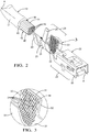
FIG. 2 is a perspective view of an electrical contact that includes a knurl pattern along a portion of a length of the electrical contact receiving a wire cable according to the invention; -
FIG. 3 shows a magnified view of the knurl pattern ofFIG. 2 , and details thereof; -
FIG. 4 shows a crimp connection that attaches the wire cable ofFIG. 2 to the electrical contact ofFIG. 2 ; -
FIG. 5 shows a cross-sectional view of the crimp connection ofFIG. 4 , through the lines 5-5; -
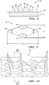
FIG. 6 shows a magnified view of the knurl pattern ofFIG. 3 , and details thereof; -
FIG. 7 shows a magnified view of recessed, rhomboid-shaped elements of the knurl pattern ofFIG. 6 ; -
FIG. 8 shows a cross-sectional view of the recessed, rhomboid-shaped elements ofFIG. 7 that include inclined ramp sidewalls, taken through the lines 8-8; -
FIG. 9 shows a magnified view of a single, recessed rhomboid-shaped element in the plurality of recessed, rhomboid-shaped elements ofFIG. 7 ; -
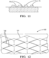
FIG. 10 shows an isometric three-dimensional view of corresponding raised protrusion elements associated with the die of the press tool used to construct the recessed, rhomboid-shaped elements ofFIG. 7 in an interior surface of the electrical contact; -
FIG. 11 shows a cross-sectional view of the corresponding elements of the die of the press tool ofFIG. 10 , along the lines 11-11; and -
FIG. 12 shows an isometric three-dimensional view of corresponding elements associated with a die of a press tool used to make recessed, rhomboid-shaped pyramidal elements in an interior surface of an electrical contact, according to an alternate embodiment of the invention. - In accordance with this invention, referring to
FIG. 2 , a wire conductor, orwire cable 10 is disposed along a longitudinal axisA. Wire cable 10 has an insulativeouter cover 12 and an aluminum-basedinner core 14. The term "aluminum-based" as used in this document herein is defined to mean pure aluminum or an aluminum alloy where aluminum is the main metal in the alloy.Outer cover 12 surroundsinner core 14.Inner core 14 is composed of wire strands that may be axially disposed ininner core 14 wheninner core 14 is received inelectrical contact 22. Alternately, inner core may be constructed of a plurality of individual wire strands that are bundled and twisted together. When the wire strands are twisted and bundled together, the lead may be axially received into the electrical contact, but the twisted wire strands may not be axially disposed therein.Wire strands 16 are useful to provide flexibility ofwire cable 10 whenwire cable 10 is installed in a wiring application (not shown), such as during the manufacture of a vehicle. Alternately, the inner core of the wire cable may be a single wire strand. An end portion (not shown) ofouter cover 12 ofwire cable 10 is removed to expose a portion ofinner core 14. Exposed portion ofinner core 14 is alead 18 ofwire cable 10.Lead 18 extends from anaxial edge 20 ofouter cover 12. - A copper-based terminal or
electrical contact 22 includes amating end 24 and anopen wing end 28.Wing end 28 receiveslead 18 along an axisA. Wing end 28 includes a pair ofinsulation wings 29 and a pair ofcore wings 31 that are axially spaced apart fromcore wings 31.Insulation wings 29 are disposed aft ofcore wings 31 along abase 21 ofelectrical contact 22 that receiveswire cable 10. The term "copper-based" as used in this document herein is defined to mean pure copper, or a copper alloy where copper is the main metal in the alloy.Electrical contact 22 may be received into a connector (not shown) that may include a plurality of electrical contacts (not shown) that are part of wiring harness (not shown) used in a vehicle (not shown) and the connector (not shown) may mate with a corresponding mating connector (not shown) used in the motorized vehicle.Mating end 24 contains a female boxelectrical contact 30 and as is known and used in the electrical contact and wiring arts.Female box contact 30 may be received into a corresponding male electrical contact (not shown), such as may be found in the corresponding mating connector (not shown) disposed in the vehicle (not shown).Female box contact 30 electrically joins an electrical signal carried oninner core 14 with another electrical circuit attached with the corresponding male receiving electrical contact. Alternately, the female mating end may be a male mating end and the electrical contact may comprise other additional sections disposed intermediate the wing and the mating end.Insulation wings 29 andcore wings 31 respectively angularly extend outwardly away frombase 21 ofelectrical contact 22.Base 21 preferably has an arcuate shape in the neutral state. The neutral state ofelectrical contact 22 is the form ofelectrical contact 22 after initial construction and before acrimp connection 46 is formed, as best illustrated inFIGS. 2 and 3 .Arcuate base 21 generally conforms to a shape oflead 18 whenwire cable 10 is received inelectrical contact 22.Insulation wings 29 are configured to crimp toouter cover 12 andcore wings 31 are configured to crimp to lead 18. -
Electrical contact 22 is chosen such thatwing end 28 is of a sufficiently large size to receivelead 18 and portion ofouter cover 12 adjacent to lead 18 to allow for an effective crimp betweenelectrical contact 22 andwire cable 10. Acore wing 31 is sized to sufficiently wrap around, cover, and engage against at least a portion oflead 18 whenwire cable 10 is crimped toelectrical contact 22.Core wing 31 includes an interior surface, or abuttingsurface 36 that engages at least a portion ofinner core 14 oflead 18 whenwire cable 10 is crimped toelectrical contact 22 to provide electrical connection betweenwire cable 10 andelectrical contact 22. Preferably,core wing 31 is sized to lead 18 so thatknurl pattern 44 engages the entire length oflead 18 and arearward edge 50 ofelectrical contact 22 is disposed adjacent to edge 20 ofouter cover 12 whencrimp connection 46 is formed. - A fluid
conformal coating 40 is disposed along at least an outer surface oflead 18 and anend 38 oflead 18. Additionally, coating 40 is also applied overedge 20 and extends on to a portion ofouter cover 12adjacent lead 18. Thus, a seal covering 42 ofcoating 40 entombs lead 18 so as to provide a corrosion-resistant protective layer forlead 18 ofwire cable 10 whenwire cable 10 is received intowing end 28 ofelectrical contact 22. "Fluid" is defined as "being able to flow." Seal covering 42 may advantageously aid in the preventing the formation of galvanic corrosion incrimp connection 46. The viscosity ofcoating 40 may be altered to allowcoating 40 to properly flow ontowire cable 10 so as to achieve a sufficient thickness ofcoating 40 to completely cover at least the outside surface oflead 18. Seal covering 42 ofcoating 40 may be applied towire cable 10 by dripping, spraying, electrolytic transfer, and brush and sponge applications, and the like. One such seal covering is described in United States Application Serial No.12/883,838 - Referring to
FIG. 3 ,electrical contact 22 includes aknurl pattern 44.Knurl pattern 44 is defined within abuttingsurface 36 ofcore wing 31 ofelectrical contact 22 along a portion of a length L ofelectrical contact 22. Length L is axially disposed along axis A. Referring toFIGS. 4-5 , whenelectrical contact 22 is attached towire cable 10 to formcrimp connection 46,knurl pattern 44 engagingly contacts against at least the outer surface oflead 18.Knurl pattern 44 may be formed, and stamped in tointerior surface 36 by using a die press, as is known in the electrical contact and wiring arts.Crimp connection 46 includes aseam 48 formed intermediate arearward edge 50 and forward edge 52 ofcore wing 31.Crimp connection 46 is part of awire assembly 49 that includeswire cable 10 andelectrical contact 22. - Referring to
FIGS. 6-9 ,knurl pattern 44 includes a plurality ofelements 54 that extend along afloor 55 underlying abuttingsurface 36. A recessedsurface 60 of eachelement 54 is adjacently disposed tofloor 55.Floor 55 is spaced apart and recessed from abuttingsurface 36. Raisedportions 65 are disposed in-between theelements 54 and have a topplanar surface 66 that is generally planar with the surrounding abutting surfaces 36. Each of the plurality ofelements 54 includes a plurality ofsidewalls 61.Edges 63 ofrespective elements 54 are formed at an interface betweensidewalls 61 and topplanar surfaces 66 of raisedportions 65. Eachelement 54 has a perimeter edge formed from a plurality ofedges 63 that surround eachelement 54. Each sidewall in the plurality ofsidewalls 61 for each element in the plurality ofelements 54 extends from recessedsurface 60 in an inclined, angled direction towards topplanar surface 66 and transition to topplanar surface 66 such that edges 63 are formed. Thus, sidewalls 61 are inclined ramps when viewed in cross section, as best illustrated inFIG. 8 . Advantageously, the plurality ofinclined sidewalls 61 assists removal of the die fromelectrical contact 22 when knurl pattern is stamped. Preferably, the incline ramps of the sidewalls have draft angle that is an acute angle in relation to a plane defined perpendicular tofloor 55. Alternately, the plurality of sidewalls for each element in the plurality of elements may be disposed in a direction perpendicular to the floor. Recessedsurface 60 for eachelement 54 is generally parallel with abuttingsurface 36 and with axis A. Raisedportions 65 adjacently surround eachelement 54 inknurl pattern 44, as best illustrated inFIGS. 7 and8 . The topplanar surfaces 66 of raisedportions 65 transitionally communicate with the surrounding abuttingsurface 36, as best illustrated inFIG. 6 . Alternately, the planar top surfaces of the raised portions may be recessed so that the planar top surfaces are disposed intermediate the floor and the surrounding abutting surface.Edges 63 are effective to fracture the aluminum oxides disposed onlead 18 ascrimp connection 46 is formed. The structure interrelationships ofsidewalls 61, edges 63, and raisedportions 65 are best illustrated inFIG. 8 .Floor 55 has a spaced, generally parallel relationship with abuttingsurface 36. Each recessedsurface 60 has a shape that includes a first pair of opposing, generally axialinner corners 56. First pair of axialinner corners 56 define a first, or axial minor distance x1 therebetween. A second pair of opposinginner corners 58 different from first pair of axialinner corners 56 define a second, or major distance x2 therebetween. Major distance x2 has a bisecting, perpendicular relationship to minor distance x1, as best illustrated inFIG. 9 . Axial minor distance x1 is less than major distance x2. Recessedsurface 60 for eachelement 54 has a surface area that forms a rhombus shape. Alternately, the axial minor distance may be substantially axial with axis A and the major distance is perpendicular to the substantial axial minor distance. For eachelement 54, first pair of axialinner corners 56 respectively have an angular value that is greater than the angular value of the respective second pair of opposinginner corners 58. Preferably, an inner corner of the first pair of axialinner corners 56 has an obtuse angular value and an inner corner of the second pair of opposinginner corners 58 has an acute angular value, as best illustrated inFIG. 9 . In a further alternate embodiment, an inner corner of the first pair of axial opposing inner corners has an obtuse angular value that may be greater than 100 degrees. - The
knurl pattern 44 ofelectrical contact 22 is not in use whenwire cable 10 is not attached, as best illustrated inFIGS. 2 and 3 . -
Knurl pattern 44 ofelectrical contact 22 is in use whenknurl pattern 44 engageslead 18 to formcrimp connection 46, as best illustrated inFIGS. 4 and 5 .Crimp connection 46 may be formed by a press as is known in the electrical contact and wiring arts. Whencrimp connection 46 is being formed, plurality ofelements 54 are urged by a force as applied by the press to engage againstaluminum lead 18 such that portions ofaluminum lead 18 extrude into plurality ofelements 54. Theedges 61 in the plurality ofelements 54 in combination with the axial minor distance x1 and major distance x2 rhombus shape orientation further assist to break up the aluminum oxides along the entire outer surface oflead 18 ofwire cable 10 so as to increase the electrical and mechanical robustness ofcrimp connection 46. - While not limited to any particular theory, it has been observed, that using plurality of
elements 54 having the orientation of axial minor distance x1 and major distance x2 assists to keepelements 54 open for a longer period of time during the crimping ofelectrical contact 22 to lead 18. Portions ofaluminum lead 18 extrude intoelements 54 against recessedsurfaces 60 so thatelements 54 engagingly close against portions of the extrudedaluminum lead 18 so that the voids (2), as shown in prior art inFIG. 1A , do not occur. Because major axis distance x2 is perpendicular to lead 18, a greater contact surface area for anyparticular wire strand 16 is more apt to have aluminum oxides disposed onindividual wire strand 16 broken up and fractured while also being extruding into recessedelements 54. A greater contact surface area of pure aluminum on at least an outer surface oflead 18 making mechanical and electrical contact with thesurface area material knurl pattern 44 oncore wing 31 ensures a more reliable and robust electrical connection. The greater surface area contact also results in enhanced mechanical interlock betweenlead 18 andcore wing 31 that assists to maintain the robust electrical contact betweenlead 18 andelectrical contact 22 incrimp connection 46. This greater surface area contact betweensurfaces FIGS. 5 and8 . Thus,knurl pattern 44 advantageously allows for a maximum electrical and mechanical connection betweenlead 18 andelectrical contact 22 whencrimp connection 46 is formed. Moreover, it is also important thatcore wings 31 are crimped in a manner so that ascrimp connection 46 is formed to a final state from the neutral state,core wing 31 maintains a generally arcuate form during the formation ofcrimp connection 46. The final state ofcore wing 31 is whencore wing 31 is formed incrimp connection 46, as best illustrated inFIG. 4 . Maintaining the arcuate form ofcore wing 31 during the crimping process allowselements 54 to remain sufficiently open for a longer time period such that portions ofaluminum lead 18 extrude intoelements 54 beforeelements 54 engagingly close partially to trap the extruded portions ofaluminum lead 18 within theclosed elements 54, as best illustrated inFIG. 5 . - Additionally, as recessed
elements 54 are formed indiagonal rows 67 whenknurl pattern 44 is formed ininterior surface 36 ofcore wing 31, the major distances x2 collectively cover the width ofcore wing 31 such that at least the entire surface area oflead 18 is impacted by plurality ofelements 54 across the length and width ofknurl pattern 44 oncore wings 31 to ensure a robust electrical connection ofwire cable 10 andelectrical conductor 22. The perimeter edges of theelements 54 inknurl pattern 44 are effective to provide increased ability forknurl pattern 44 to fracture aluminum oxides onlead 18 whencrimp connection 46 is formed. - It has been observed when
crimp connection 46 is analyzed andcore wings 31 are unwrapped fromlead 18, a substantial portion ofknurl pattern 44 is left impressed in the outer surface oflead 18 ofwire cable 10. For many analyzed crimp connections, one hundred percent (100%) of the knurl pattern is left impressed on the leads of the respective wire cables. - Alternately, referring to
FIGS. 10 and11 , acorresponding knurl pattern 70 is associated with a die of a die press (not shown) as is known and used in the electrical contact and wiring arts. To construct plurality of recessedelements 54 inknurl pattern 44 ofelectrical contact 22, raisedrhomboid protrusions 71 ofknurl pattern 70 are utilized on the die used in the die press.Grooves 72 surround eachrhomboid protrusion 71 inknurl pattern 70 disposed on the die. The die containingknurl pattern 70 is constructed from hardened metal that is harder than the electrical contact or terminal, such as using a hardened carbide steel.Grooves 72 preferably have a deeper depth than a depth of raisedportions 65 ofknurl pattern 44 as measured fromfloor 55. - Alternately, referring to
FIG. 12 , a die employs pyramidal rhomboid-shapedprotrusions 101 and associatedadjacent grooves 102 may be utilized. Pyramidal rhomboid-shapedprotrusions 101 each have a flattened truncated top. When the die employing pyramidal rhomboid-shapedprotrusions 101 and associatedgrooves 102 is used to stamp a recessed knurl pattern on the core wings and base of the electrical contact, a plurality of recessed pyramidal rhomboid-shaped elements is defined in the interior surface of the electrical contact. Each flattened truncated top is in each recessed pyramidal rhomboid-shaped element is disposed adjacent a floor of the interior surface of the electrical contact. The die of the embodiment ofFIG. 12 is made from similar materials as the die of the embodiment shown inFIGS. 10 and11 as previously discussed herein. - Alternately, the wire cable may be constructed from a non-aluminum, electrically conductive material and the electrical contact may be constructed from any suitable electrically conductive material.
- Still yet alternately, the knurl pattern may be employed along any portion of the length and width of the interior surface of the electrical contact that makes contact with at least a portion of a lead of a wire cable.
- In another alternate embodiment, the wire assembly may be associated with an electrical connection system used in any type of electrical application that requires a robust electrical connection.
- In yet another alternate embodiment, the inner core of a wire cable may include a lead that has a plurality of wire strands that are compacted or welded together. One such welded lead is described in United States Application Serial No.
13/168,309 - Thus, an electrical contact that includes a knurl pattern having a plurality of recessed rhombic elements has been presented. Each recessed rhombic element has an orientation relative to a wire cable received in the electrical contact that allows for an improved electrical and mechanical connection between the electrical contact and the aluminum wire cable. Each recessed rhombic element has an axial minor distance disposed between axial inner corners. Each rhombic element further includes a major distance disposed between non-axial inner corners. The axial minor distance is less than the major distance. The recessed rhomboid elements may be disposed along any amount of the interior surfaces of the electrical contact that axially receives a lead of the wire cable. The knurl pattern extends along a width of the core wings and along an arcuate base of the electrical contact defined in an interior surface of the electrical contact. The crimping process maintains the arcuate form of the base while also crimping the core wings in an arcuate form all that way from a neutral state to a final state as the crimp connection is constructed. This crimping process allows at least a substantial portion of the recessed rhomboid elements to fill with the extruded aluminum of the lead before the recessed rhomboid elements are partially closed to ensure voids, as shown in prior art
FIG. 1A , do not occur. When a substantial portion of the recessed rhomboid elements are filled with pure aluminum where the pure aluminum makes complete contact with a substantial portion of the surface area of the recessed surface of the rhomboid elements, a greater surface contact area between the aluminum lead and electrical contact is realized that ensures an enhanced mechanical and electrical crimp connection is attained over the service life of the wire assembly. The increased perimeter distance of the summation of the edges in the plurality of elements of the knurl pattern in combination with the axial minor distance orientation of each rhomboid element ensure the aluminum oxides disposed on the lead of the wire cable are more effectively fractured and broken along at least the outer surface of the lead along the length of the lead that is encompassed by the knurl pattern when the crimp connection is formed. - While this invention has been described in terms of the preferred embodiment thereof, it is not intended to be so limited, but rather only to the extent set forth in the claims that follow.
- It will be readily understood by those persons skilled in the art that the present invention is susceptible of broad utility and application. Many embodiments and adaptations of the present invention other than those described above, as well as many variations, modifications and equivalent arrangements, will be apparent from or reasonably suggested by the present invention and the foregoing description, without departing from the substance or scope of the present invention. Accordingly, while the present invention has been described herein in detail in relation to its embodiments, it is to be understood that this disclosure is only illustrative and exemplary of the present invention and is made merely for purposes of providing a full and enabling disclosure of the invention.
Claims (12)
- An electrical contact (22) comprising:a core wing (31) configured to crimp to a lead (18) of a wire cable (10), the core wing (31) comprising an interior surface (36);a knurl pattern (44) defined in the interior surface (36) of the electrical contact (22) along a portion of a length (L) of the electrical contact (22), the length (L) being disposed along a longitudinal axis (A) and the portion configured to receive the lead (18) of the wire cable (10) along the axis for attachment thereto thereby allowing the lead (18) to engagingly contact against the knurl pattern (44), the knurl pattern (44) including a plurality of elements (54), each element (54) in the plurality of elements (54) has a rhombus shape that includes a plurality of inner corners, a first pair of opposing axial inner corners (56) defining an axial minor distance (x1) therebetween and a second pair of opposing inner corners (58) different from said first pair of opposing inner corners (56) defining a major distance (x2) therebetween, wherein said axial minor distance (x1) is less than said major distance (x2), and the major distance (x2) is bisecting and perpendicular to the axial minor distance (x1),characterized in that the axial minor distance (x1) is axial with the longitudinal axis(A)
- The electrical contact (22) according to claim 1, wherein each element (54) in the plurality of elements (54) includes a recessed surface (60) in relation to said interior surface (36).
- The electrical contact (22) according to claim 1, wherein each element (54) in the plurality of elements (54) includes a recessed surface (60) having an area that forms a rhombus shape.
- The electrical contact (22) according to claim 3, wherein at least an outer surface of the lead (18) is engaged against a portion of the rhombus-shaped surfaces (60) in each element (54) in the plurality of elements (54).
- The electrical contact (22) according to claim 1, wherein the recessed surface (60) of each element (54) in the plurality of elements (54) is adjacently disposed to a floor (55) of the portion, wherein the floor (55) is parallel to the interior surface (36) and is underlying the interior surface (36).
- The electrical contact (22) according to claim 1, wherein the first pair of opposing inner corners (56) respectively have an obtuse angular value, and the second pair of opposing inner corners (58) respectively have acute angular value.
- The electrical contact (22) according to claim 1, wherein the plurality of elements (54) comprise sidewalls (61), and said sidewalls (61) include inclined ramps.
- The electrical contact (22) according to claim 1, wherein the electrical contact (22) comprises a base (21) configured to receive the lead (18) of the wire cable (10), and the base (21) has an arcuate shape, and the knurl pattern (44) is disposed along at least a portion of the arcuate-shaped base (21).
- The electrical contact (22) according to claim 1, wherein when the lead (18) is attached to the portion of the electrical contact (22), a crimp connection (46) is formed between the lead (18) and the wire cable (10).
- The electrical contact (22) according to claim 9, wherein an inner core (14) of said wire cable (10) includes said lead (18) and said inner core (14) comprises aluminum or aluminum alloy, and the plurality of elements (54) include recessed external surfaces (60) in relation to said interior surface (36), and when the crimp connection (46) is formed, the aluminum lead (18) is urged against a substantial portion of said recessed external surfaces (60) associated with the plurality of elements (54).
- The electrical contact (22) according to claim 9, wherein the crimp connection (46) is associated with a cable harness disposed in a motorized vehicle.
- An electrical connection system comprising:at least one connector that includes one or more electrical contacts according to one of the preceding claims and the one or more electrical contacts are in electrical connection with one or more wire cables (10).
Applications Claiming Priority (2)
| Application Number | Priority Date | Filing Date | Title |
|---|---|---|---|
| US13/288,561 US8485853B2 (en) | 2011-11-03 | 2011-11-03 | Electrical contact having knurl pattern with recessed rhombic elements that each have an axial minor distance |
| PCT/US2012/056564 WO2013066512A1 (en) | 2011-11-03 | 2012-09-21 | Electrical contact having rhombic knurl pattern |
Publications (3)
| Publication Number | Publication Date |
|---|---|
| EP2774223A1 EP2774223A1 (en) | 2014-09-10 |
| EP2774223A4 EP2774223A4 (en) | 2015-07-08 |
| EP2774223B1 true EP2774223B1 (en) | 2017-07-19 |
Family
ID=48192578
Family Applications (1)
| Application Number | Title | Priority Date | Filing Date |
|---|---|---|---|
| EP12846072.2A Active EP2774223B1 (en) | 2011-11-03 | 2012-09-21 | Electrical contact having rhombic knurl pattern |
Country Status (7)
| Country | Link |
|---|---|
| US (1) | US8485853B2 (en) |
| EP (1) | EP2774223B1 (en) |
| JP (1) | JP5908987B2 (en) |
| KR (1) | KR101357976B1 (en) |
| CN (1) | CN103460509B (en) |
| BR (1) | BR112013016842A2 (en) |
| WO (1) | WO2013066512A1 (en) |
Families Citing this family (34)
| Publication number | Priority date | Publication date | Assignee | Title |
|---|---|---|---|---|
| JP5690095B2 (en) * | 2010-08-04 | 2015-03-25 | 矢崎総業株式会社 | Crimp terminal |
| JP5634787B2 (en) * | 2010-08-04 | 2014-12-03 | 矢崎総業株式会社 | Crimp terminal |
| JP5634788B2 (en) * | 2010-08-05 | 2014-12-03 | 矢崎総業株式会社 | Crimp terminal |
| JP5777357B2 (en) * | 2011-03-08 | 2015-09-09 | 矢崎総業株式会社 | Crimp terminal |
| JP5695987B2 (en) * | 2011-07-01 | 2015-04-08 | 矢崎総業株式会社 | Single core wire and terminal crimping structure of single core wire |
| JP5890992B2 (en) * | 2011-10-05 | 2016-03-22 | 矢崎総業株式会社 | Crimp terminal |
| US8622774B2 (en) * | 2011-11-07 | 2014-01-07 | Delphi Technologies, Inc. | Electrical contact having channel with angled sidewalls and romboid knurl pattern |
| JP5909345B2 (en) * | 2011-11-11 | 2016-04-26 | 矢崎総業株式会社 | Connector terminal |
| JP5829937B2 (en) * | 2012-02-15 | 2015-12-09 | 矢崎総業株式会社 | Terminal connection structure |
| WO2014024938A1 (en) * | 2012-08-07 | 2014-02-13 | 古河電気工業株式会社 | Crimping terminal, connection structure, connector, wire harness, crimping terminal manufacturing method, and connection structure manufacturing method |
| US20140273594A1 (en) | 2013-03-14 | 2014-09-18 | Delphi Technologies, Inc. | Shielded cable assembly |
| US9362659B2 (en) | 2013-12-10 | 2016-06-07 | Delphi Technologies, Inc. | Electrical connector terminal |
| US9142907B2 (en) | 2013-12-10 | 2015-09-22 | Delphi Technologies, Inc. | Electrical connection system |
| JP2015130326A (en) | 2013-12-10 | 2015-07-16 | デルファイ・テクノロジーズ・インコーポレーテッド | Shielded cable assembly |
| US9698501B2 (en) | 2013-12-10 | 2017-07-04 | Delphi Technologies Inc. | Electrical shield connector |
| US20150162704A1 (en) | 2013-12-10 | 2015-06-11 | Delphi Technologies, Inc. | Low profile connector locking mechanism |
| US9937583B2 (en) | 2013-12-24 | 2018-04-10 | Innovative Weld Solutions Ltd. | Welding assembly and method |
| US9649717B2 (en) | 2013-12-24 | 2017-05-16 | Innovative Weld Solutions, Ltd. | Welding assembly and method |
| KR101664576B1 (en) * | 2014-11-07 | 2016-10-10 | 현대자동차주식회사 | Wire terminal connector |
| JP2016164836A (en) * | 2015-03-06 | 2016-09-08 | 株式会社オートネットワーク技術研究所 | Electric wire with terminal and terminal |
| CN107429976B (en) | 2015-03-16 | 2021-02-09 | 达纳加拿大公司 | Heat exchanger with plate having surface pattern for improving flatness and method of manufacturing the same |
| JP6376030B2 (en) * | 2015-04-16 | 2018-08-22 | 株式会社オートネットワーク技術研究所 | Terminal and electric wire with terminal |
| US10532628B2 (en) | 2015-05-05 | 2020-01-14 | Mahle International Gmbh | HVAC module having a reconfigurable bi-level duct system |
| KR20160137381A (en) | 2015-05-20 | 2016-11-30 | 델피 테크놀로지스 인코포레이티드 | Shielded cable assembly |
| EP3098905A1 (en) | 2015-05-28 | 2016-11-30 | Delphi Technologies, Inc. | Electrical shield connector |
| DE102015209855A1 (en) * | 2015-05-28 | 2016-12-01 | Te Connectivity Germany Gmbh | Electrical contacting element with a finely structured contacting surface |
| US10511008B2 (en) | 2016-03-17 | 2019-12-17 | Tti (Macao Commercial Offshore) Limited | Battery contact with a surface texture |
| JP6904147B2 (en) * | 2017-08-01 | 2021-07-14 | 株式会社オートネットワーク技術研究所 | Wire with terminal |
| US10741975B2 (en) * | 2018-10-19 | 2020-08-11 | Aptiv Technologies Limited | Sheilded cable assembly and electromagnetic shield terminal assembly for same |
| US10950954B2 (en) | 2019-04-30 | 2021-03-16 | Lear Corporation | Terminal assembly and method |
| US11271329B2 (en) * | 2020-02-06 | 2022-03-08 | Aptiv Technologies Limited | Electrical terminal and method of forming same |
| US11469557B2 (en) | 2020-07-28 | 2022-10-11 | Aptiv Technologies Limited | Coaxial electrical connector |
| US11387585B2 (en) * | 2020-08-05 | 2022-07-12 | Aptiv Technologies Limited | Anti-fretting/multiple contact terminal using knurl pattern |
| US11646510B2 (en) * | 2021-04-29 | 2023-05-09 | Aptiv Technologies Limited | Shielding electrical terminal with knurling on inner contact walls |
Family Cites Families (20)
| Publication number | Priority date | Publication date | Assignee | Title |
|---|---|---|---|---|
| JPH05152011A (en) | 1991-11-26 | 1993-06-18 | Sumitomo Wiring Syst Ltd | Crimp-style terminal |
| DE19549174A1 (en) * | 1995-10-28 | 1997-07-03 | Bosch Gmbh Robert | Contact element with crimp section |
| JP2003243057A (en) | 2002-02-18 | 2003-08-29 | Auto Network Gijutsu Kenkyusho:Kk | Terminal for connection of electric wire |
| JP2003338334A (en) * | 2002-05-20 | 2003-11-28 | Yazaki Corp | Female terminal, connecting structure thereof and wiring harness |
| US20050273122A1 (en) | 2004-06-02 | 2005-12-08 | Microline, Inc. | Clip with enhanced gripping arrangement |
| FR2877150B1 (en) | 2004-10-27 | 2007-01-19 | Radiall Sa | METHOD FOR MOUNTING AN ELECTRICAL CONNECTOR ON A COAXIAL CABLE, AND SUCH A CONNECTOR |
| JP4520933B2 (en) | 2005-11-18 | 2010-08-11 | 矢崎総業株式会社 | Terminal chain, crimper for crimping the terminal chain, terminal chain manufacturing method, and connection structure of a plurality of terminal fittings and a flat circuit body |
| JP4834605B2 (en) * | 2007-05-15 | 2011-12-14 | 株式会社オートネットワーク技術研究所 | Outer conductor terminal |
| US8303354B2 (en) * | 2008-02-15 | 2012-11-06 | Sumitomo Wiring Systems, Ltd. | Terminal connector and wire harness |
| JP5400318B2 (en) | 2008-04-15 | 2014-01-29 | 矢崎総業株式会社 | Crimp terminal for aluminum wire |
| JP2009272240A (en) * | 2008-05-09 | 2009-11-19 | Autonetworks Technologies Ltd | Electric wire with terminal |
| JP5058082B2 (en) * | 2008-06-18 | 2012-10-24 | 株式会社オートネットワーク技術研究所 | Terminal fittings and electric wires with terminals |
| JP4996553B2 (en) * | 2008-06-20 | 2012-08-08 | 株式会社オートネットワーク技術研究所 | Terminal fittings and electric wires with terminals |
| WO2010007843A1 (en) * | 2008-07-15 | 2010-01-21 | 住友電装株式会社 | Terminal fitting and electrical wire with terminal fitting |
| JP5071288B2 (en) * | 2008-07-22 | 2012-11-14 | 住友電装株式会社 | Terminal fittings and wires with terminal fittings |
| US20100087104A1 (en) | 2008-10-02 | 2010-04-08 | Gump Bruce S | Terminal crimp having knurl with omega-shaped cross-section |
| US7722416B2 (en) * | 2008-10-02 | 2010-05-25 | Delphi Technologies, Inc. | Electrical connection system for use on aluminum wires |
| JP4979147B2 (en) * | 2009-04-24 | 2012-07-18 | 株式会社オートネットワーク技術研究所 | Terminal fittings and electric wires with terminal fittings |
| US8181343B2 (en) | 2009-10-08 | 2012-05-22 | Delphi Technologies, Inc. | Sealed crimp connection methods |
| JP4790851B2 (en) * | 2010-03-11 | 2011-10-12 | 株式会社 ピー・エル | Aluminum body connection structure and connector |
-
2011
- 2011-11-03 US US13/288,561 patent/US8485853B2/en active Active
-
2012
- 2012-09-21 CN CN201280016590.6A patent/CN103460509B/en active Active
- 2012-09-21 BR BR112013016842A patent/BR112013016842A2/en active Search and Examination
- 2012-09-21 WO PCT/US2012/056564 patent/WO2013066512A1/en active Application Filing
- 2012-09-21 EP EP12846072.2A patent/EP2774223B1/en active Active
- 2012-09-21 JP JP2014539955A patent/JP5908987B2/en active Active
- 2012-09-21 KR KR1020137020346A patent/KR101357976B1/en active IP Right Grant
Non-Patent Citations (1)
| Title |
|---|
| None * |
Also Published As
| Publication number | Publication date |
|---|---|
| EP2774223A4 (en) | 2015-07-08 |
| KR20130099233A (en) | 2013-09-05 |
| US8485853B2 (en) | 2013-07-16 |
| WO2013066512A1 (en) | 2013-05-10 |
| KR101357976B1 (en) | 2014-02-03 |
| JP5908987B2 (en) | 2016-04-26 |
| BR112013016842A2 (en) | 2016-09-27 |
| EP2774223A1 (en) | 2014-09-10 |
| CN103460509A (en) | 2013-12-18 |
| US20130115828A1 (en) | 2013-05-09 |
| CN103460509B (en) | 2016-03-02 |
| JP2014532969A (en) | 2014-12-08 |
Similar Documents
| Publication | Publication Date | Title |
|---|---|---|
| EP2774223B1 (en) | Electrical contact having rhombic knurl pattern | |
| US8622774B2 (en) | Electrical contact having channel with angled sidewalls and romboid knurl pattern | |
| US10205252B2 (en) | Connecting structure of crimp terminal and electric wire | |
| US7867014B2 (en) | Press-clamping terminal for aluminum wire | |
| US8177591B2 (en) | Terminal fitting and electrical cable equipped with the same | |
| US9293838B2 (en) | Aluminum cable provided with crimping terminal | |
| CA2814091C (en) | Electrical terminal for terminating a wire | |
| KR101100950B1 (en) | Terminal connector and electric wire with terminal connector | |
| US2800638A (en) | Electric connector | |
| US9502784B2 (en) | Terminal attached aluminum electric wire | |
| EP2424044A1 (en) | Terminal fitting and terminal fitting-equipped electric cable | |
| JP2015201269A (en) | Connection structure of crimp terminal and wire | |
| US20160276777A1 (en) | Terminal-attached electric wire | |
| JP2009087848A (en) | Crimp terminal for aluminum wire and method of crimping terminal of aluminum wire | |
| EP2151894A1 (en) | A terminal fitting, a wire connected with a terminal fitting and a connecting method therefor | |
| US10886686B2 (en) | Method for crimping an electrical contact to a cable and tool for implementing said method |
Legal Events
| Date | Code | Title | Description |
|---|---|---|---|
| PUAI | Public reference made under article 153(3) epc to a published international application that has entered the european phase |
Free format text: ORIGINAL CODE: 0009012 |
|
| 17P | Request for examination filed |
Effective date: 20131007 |
|
| AK | Designated contracting states |
Kind code of ref document: A1 Designated state(s): AL AT BE BG CH CY CZ DE DK EE ES FI FR GB GR HR HU IE IS IT LI LT LU LV MC MK MT NL NO PL PT RO RS SE SI SK SM TR |
|
| DAX | Request for extension of the european patent (deleted) | ||
| RA4 | Supplementary search report drawn up and despatched (corrected) |
Effective date: 20150609 |
|
| RIC1 | Information provided on ipc code assigned before grant |
Ipc: H01R 9/05 20060101AFI20150602BHEP Ipc: H01R 4/18 20060101ALI20150602BHEP |
|
| 17Q | First examination report despatched |
Effective date: 20150720 |
|
| GRAP | Despatch of communication of intention to grant a patent |
Free format text: ORIGINAL CODE: EPIDOSNIGR1 |
|
| INTG | Intention to grant announced |
Effective date: 20170208 |
|
| GRAS | Grant fee paid |
Free format text: ORIGINAL CODE: EPIDOSNIGR3 |
|
| GRAA | (expected) grant |
Free format text: ORIGINAL CODE: 0009210 |
|
| AK | Designated contracting states |
Kind code of ref document: B1 Designated state(s): AL AT BE BG CH CY CZ DE DK EE ES FI FR GB GR HR HU IE IS IT LI LT LU LV MC MK MT NL NO PL PT RO RS SE SI SK SM TR |
|
| REG | Reference to a national code |
Ref country code: GB Ref legal event code: FG4D |
|
| REG | Reference to a national code |
Ref country code: CH Ref legal event code: EP |
|
| REG | Reference to a national code |
Ref country code: IE Ref legal event code: FG4D |
|
| REG | Reference to a national code |
Ref country code: AT Ref legal event code: REF Ref document number: 911222 Country of ref document: AT Kind code of ref document: T Effective date: 20170815 |
|
| REG | Reference to a national code |
Ref country code: DE Ref legal event code: R096 Ref document number: 602012034859 Country of ref document: DE |
|
| REG | Reference to a national code |
Ref country code: FR Ref legal event code: PLFP Year of fee payment: 6 |
|
| REG | Reference to a national code |
Ref country code: NL Ref legal event code: MP Effective date: 20170719 |
|
| REG | Reference to a national code |
Ref country code: LT Ref legal event code: MG4D |
|
| REG | Reference to a national code |
Ref country code: AT Ref legal event code: MK05 Ref document number: 911222 Country of ref document: AT Kind code of ref document: T Effective date: 20170719 |
|
| PG25 | Lapsed in a contracting state [announced via postgrant information from national office to epo] |
Ref country code: HR Free format text: LAPSE BECAUSE OF FAILURE TO SUBMIT A TRANSLATION OF THE DESCRIPTION OR TO PAY THE FEE WITHIN THE PRESCRIBED TIME-LIMIT Effective date: 20170719 Ref country code: NO Free format text: LAPSE BECAUSE OF FAILURE TO SUBMIT A TRANSLATION OF THE DESCRIPTION OR TO PAY THE FEE WITHIN THE PRESCRIBED TIME-LIMIT Effective date: 20171019 Ref country code: NL Free format text: LAPSE BECAUSE OF FAILURE TO SUBMIT A TRANSLATION OF THE DESCRIPTION OR TO PAY THE FEE WITHIN THE PRESCRIBED TIME-LIMIT Effective date: 20170719 Ref country code: AT Free format text: LAPSE BECAUSE OF FAILURE TO SUBMIT A TRANSLATION OF THE DESCRIPTION OR TO PAY THE FEE WITHIN THE PRESCRIBED TIME-LIMIT Effective date: 20170719 Ref country code: FI Free format text: LAPSE BECAUSE OF FAILURE TO SUBMIT A TRANSLATION OF THE DESCRIPTION OR TO PAY THE FEE WITHIN THE PRESCRIBED TIME-LIMIT Effective date: 20170719 Ref country code: SE Free format text: LAPSE BECAUSE OF FAILURE TO SUBMIT A TRANSLATION OF THE DESCRIPTION OR TO PAY THE FEE WITHIN THE PRESCRIBED TIME-LIMIT Effective date: 20170719 Ref country code: LT Free format text: LAPSE BECAUSE OF FAILURE TO SUBMIT A TRANSLATION OF THE DESCRIPTION OR TO PAY THE FEE WITHIN THE PRESCRIBED TIME-LIMIT Effective date: 20170719 |
|
| PG25 | Lapsed in a contracting state [announced via postgrant information from national office to epo] |
Ref country code: IS Free format text: LAPSE BECAUSE OF FAILURE TO SUBMIT A TRANSLATION OF THE DESCRIPTION OR TO PAY THE FEE WITHIN THE PRESCRIBED TIME-LIMIT Effective date: 20171119 Ref country code: GR Free format text: LAPSE BECAUSE OF FAILURE TO SUBMIT A TRANSLATION OF THE DESCRIPTION OR TO PAY THE FEE WITHIN THE PRESCRIBED TIME-LIMIT Effective date: 20171020 Ref country code: BG Free format text: LAPSE BECAUSE OF FAILURE TO SUBMIT A TRANSLATION OF THE DESCRIPTION OR TO PAY THE FEE WITHIN THE PRESCRIBED TIME-LIMIT Effective date: 20171019 Ref country code: PL Free format text: LAPSE BECAUSE OF FAILURE TO SUBMIT A TRANSLATION OF THE DESCRIPTION OR TO PAY THE FEE WITHIN THE PRESCRIBED TIME-LIMIT Effective date: 20170719 Ref country code: LV Free format text: LAPSE BECAUSE OF FAILURE TO SUBMIT A TRANSLATION OF THE DESCRIPTION OR TO PAY THE FEE WITHIN THE PRESCRIBED TIME-LIMIT Effective date: 20170719 Ref country code: RS Free format text: LAPSE BECAUSE OF FAILURE TO SUBMIT A TRANSLATION OF THE DESCRIPTION OR TO PAY THE FEE WITHIN THE PRESCRIBED TIME-LIMIT Effective date: 20170719 Ref country code: ES Free format text: LAPSE BECAUSE OF FAILURE TO SUBMIT A TRANSLATION OF THE DESCRIPTION OR TO PAY THE FEE WITHIN THE PRESCRIBED TIME-LIMIT Effective date: 20170719 |
|
| REG | Reference to a national code |
Ref country code: DE Ref legal event code: R097 Ref document number: 602012034859 Country of ref document: DE |
|
| PG25 | Lapsed in a contracting state [announced via postgrant information from national office to epo] |
Ref country code: CZ Free format text: LAPSE BECAUSE OF FAILURE TO SUBMIT A TRANSLATION OF THE DESCRIPTION OR TO PAY THE FEE WITHIN THE PRESCRIBED TIME-LIMIT Effective date: 20170719 Ref country code: RO Free format text: LAPSE BECAUSE OF FAILURE TO SUBMIT A TRANSLATION OF THE DESCRIPTION OR TO PAY THE FEE WITHIN THE PRESCRIBED TIME-LIMIT Effective date: 20170719 Ref country code: DK Free format text: LAPSE BECAUSE OF FAILURE TO SUBMIT A TRANSLATION OF THE DESCRIPTION OR TO PAY THE FEE WITHIN THE PRESCRIBED TIME-LIMIT Effective date: 20170719 |
|
| REG | Reference to a national code |
Ref country code: CH Ref legal event code: PL |
|
| PLBE | No opposition filed within time limit |
Free format text: ORIGINAL CODE: 0009261 |
|
| STAA | Information on the status of an ep patent application or granted ep patent |
Free format text: STATUS: NO OPPOSITION FILED WITHIN TIME LIMIT |
|
| PG25 | Lapsed in a contracting state [announced via postgrant information from national office to epo] |
Ref country code: MC Free format text: LAPSE BECAUSE OF FAILURE TO SUBMIT A TRANSLATION OF THE DESCRIPTION OR TO PAY THE FEE WITHIN THE PRESCRIBED TIME-LIMIT Effective date: 20170719 Ref country code: EE Free format text: LAPSE BECAUSE OF FAILURE TO SUBMIT A TRANSLATION OF THE DESCRIPTION OR TO PAY THE FEE WITHIN THE PRESCRIBED TIME-LIMIT Effective date: 20170719 Ref country code: SK Free format text: LAPSE BECAUSE OF FAILURE TO SUBMIT A TRANSLATION OF THE DESCRIPTION OR TO PAY THE FEE WITHIN THE PRESCRIBED TIME-LIMIT Effective date: 20170719 Ref country code: IT Free format text: LAPSE BECAUSE OF FAILURE TO SUBMIT A TRANSLATION OF THE DESCRIPTION OR TO PAY THE FEE WITHIN THE PRESCRIBED TIME-LIMIT Effective date: 20170719 Ref country code: SM Free format text: LAPSE BECAUSE OF FAILURE TO SUBMIT A TRANSLATION OF THE DESCRIPTION OR TO PAY THE FEE WITHIN THE PRESCRIBED TIME-LIMIT Effective date: 20170719 |
|
| 26N | No opposition filed |
Effective date: 20180420 |
|
| REG | Reference to a national code |
Ref country code: IE Ref legal event code: MM4A |
|
| REG | Reference to a national code |
Ref country code: BE Ref legal event code: MM Effective date: 20170930 |
|
| PG25 | Lapsed in a contracting state [announced via postgrant information from national office to epo] |
Ref country code: LU Free format text: LAPSE BECAUSE OF NON-PAYMENT OF DUE FEES Effective date: 20170921 |
|
| PG25 | Lapsed in a contracting state [announced via postgrant information from national office to epo] |
Ref country code: IE Free format text: LAPSE BECAUSE OF NON-PAYMENT OF DUE FEES Effective date: 20170921 Ref country code: CH Free format text: LAPSE BECAUSE OF NON-PAYMENT OF DUE FEES Effective date: 20170930 Ref country code: LI Free format text: LAPSE BECAUSE OF NON-PAYMENT OF DUE FEES Effective date: 20170930 |
|
| PG25 | Lapsed in a contracting state [announced via postgrant information from national office to epo] |
Ref country code: SI Free format text: LAPSE BECAUSE OF FAILURE TO SUBMIT A TRANSLATION OF THE DESCRIPTION OR TO PAY THE FEE WITHIN THE PRESCRIBED TIME-LIMIT Effective date: 20170719 Ref country code: BE Free format text: LAPSE BECAUSE OF NON-PAYMENT OF DUE FEES Effective date: 20170930 |
|
| REG | Reference to a national code |
Ref country code: FR Ref legal event code: PLFP Year of fee payment: 7 |
|
| PG25 | Lapsed in a contracting state [announced via postgrant information from national office to epo] |
Ref country code: MT Free format text: LAPSE BECAUSE OF NON-PAYMENT OF DUE FEES Effective date: 20170921 |
|
| REG | Reference to a national code |
Ref country code: DE Ref legal event code: R081 Ref document number: 602012034859 Country of ref document: DE Owner name: APTIV TECHNOLOGIES LIMITED, BB Free format text: FORMER OWNER: DELPHI TECHNOLOGIES, INC., TROY, MICH., US |
|
| REG | Reference to a national code |
Ref country code: GB Ref legal event code: 732E Free format text: REGISTERED BETWEEN 20190117 AND 20190123 |
|
| REG | Reference to a national code |
Ref country code: GB Ref legal event code: 732E Free format text: REGISTERED BETWEEN 20190124 AND 20190130 |
|
| PG25 | Lapsed in a contracting state [announced via postgrant information from national office to epo] |
Ref country code: HU Free format text: LAPSE BECAUSE OF FAILURE TO SUBMIT A TRANSLATION OF THE DESCRIPTION OR TO PAY THE FEE WITHIN THE PRESCRIBED TIME-LIMIT; INVALID AB INITIO Effective date: 20120921 |
|
| PG25 | Lapsed in a contracting state [announced via postgrant information from national office to epo] |
Ref country code: CY Free format text: LAPSE BECAUSE OF FAILURE TO SUBMIT A TRANSLATION OF THE DESCRIPTION OR TO PAY THE FEE WITHIN THE PRESCRIBED TIME-LIMIT Effective date: 20170719 |
|
| PG25 | Lapsed in a contracting state [announced via postgrant information from national office to epo] |
Ref country code: MK Free format text: LAPSE BECAUSE OF FAILURE TO SUBMIT A TRANSLATION OF THE DESCRIPTION OR TO PAY THE FEE WITHIN THE PRESCRIBED TIME-LIMIT Effective date: 20170719 |
|
| PG25 | Lapsed in a contracting state [announced via postgrant information from national office to epo] |
Ref country code: TR Free format text: LAPSE BECAUSE OF FAILURE TO SUBMIT A TRANSLATION OF THE DESCRIPTION OR TO PAY THE FEE WITHIN THE PRESCRIBED TIME-LIMIT Effective date: 20170719 |
|
| PG25 | Lapsed in a contracting state [announced via postgrant information from national office to epo] |
Ref country code: PT Free format text: LAPSE BECAUSE OF FAILURE TO SUBMIT A TRANSLATION OF THE DESCRIPTION OR TO PAY THE FEE WITHIN THE PRESCRIBED TIME-LIMIT Effective date: 20170719 |
|
| PG25 | Lapsed in a contracting state [announced via postgrant information from national office to epo] |
Ref country code: AL Free format text: LAPSE BECAUSE OF FAILURE TO SUBMIT A TRANSLATION OF THE DESCRIPTION OR TO PAY THE FEE WITHIN THE PRESCRIBED TIME-LIMIT Effective date: 20170719 |
|
| P01 | Opt-out of the competence of the unified patent court (upc) registered |
Effective date: 20230425 |
|
| PGFP | Annual fee paid to national office [announced via postgrant information from national office to epo] |
Ref country code: GB Payment date: 20230914 Year of fee payment: 12 |
|
| PGFP | Annual fee paid to national office [announced via postgrant information from national office to epo] |
Ref country code: FR Payment date: 20230912 Year of fee payment: 12 Ref country code: DE Payment date: 20230921 Year of fee payment: 12 |