EP2773541B1 - Improved device for the washing of the wheels of a vehicle in a vehicles washing installation and respective new washing cycles performed with this device - Google Patents
Improved device for the washing of the wheels of a vehicle in a vehicles washing installation and respective new washing cycles performed with this device Download PDFInfo
- Publication number
- EP2773541B1 EP2773541B1 EP12790451.4A EP12790451A EP2773541B1 EP 2773541 B1 EP2773541 B1 EP 2773541B1 EP 12790451 A EP12790451 A EP 12790451A EP 2773541 B1 EP2773541 B1 EP 2773541B1
- Authority
- EP
- European Patent Office
- Prior art keywords
- washing
- rotating
- vehicle
- wheel
- wheels
- Prior art date
- Legal status (The legal status is an assumption and is not a legal conclusion. Google has not performed a legal analysis and makes no representation as to the accuracy of the status listed.)
- Active
Links
Images



Classifications
-
- B—PERFORMING OPERATIONS; TRANSPORTING
- B60—VEHICLES IN GENERAL
- B60S—SERVICING, CLEANING, REPAIRING, SUPPORTING, LIFTING, OR MANOEUVRING OF VEHICLES, NOT OTHERWISE PROVIDED FOR
- B60S3/00—Vehicle cleaning apparatus not integral with vehicles
- B60S3/04—Vehicle cleaning apparatus not integral with vehicles for exteriors of land vehicles
- B60S3/042—Wheel cleaning devices
-
- B—PERFORMING OPERATIONS; TRANSPORTING
- B60—VEHICLES IN GENERAL
- B60S—SERVICING, CLEANING, REPAIRING, SUPPORTING, LIFTING, OR MANOEUVRING OF VEHICLES, NOT OTHERWISE PROVIDED FOR
- B60S3/00—Vehicle cleaning apparatus not integral with vehicles
- B60S3/04—Vehicle cleaning apparatus not integral with vehicles for exteriors of land vehicles
- B60S3/06—Vehicle cleaning apparatus not integral with vehicles for exteriors of land vehicles with rotary bodies contacting the vehicle
Definitions
- the present invention relates in general to the field of installations for the washing of motor vehicles, and more particularly it relates to a device which is specifically intended for the washing of the wheels of a motor vehicle to be washed in one of these washing installations.
- Washing installations for motor vehicles currently available and in use on the market, often integrate functions and/or one or more devices specifically designed for and dedicated to the washing of the wheels, i.e. of the respective rims, of the single motor vehicle which is intended to be washed in the same washing installation.
- This device for the washing of the wheels of a vehicle is additional with respect to the other means and devices, such as rotary brushes, vertical and horizontal, nozzles for ejecting detergent products and water under pressure, blowing mouths, etc., which, as is known, equip the installation for the purpose of performing the complete washing of the vehicle, and in particular of its external bodywork.
- devices have been tested, for the washing of the wheels of a vehicle, which can also be installed in a more general installation for the washing of motor vehicles, which comprise a rotating member, in turn provided with several rotating arms, each one equipped with one or more nozzles for the dispensing, on the wheel to be washed, of a specific chemical product for the cleaning of the wheels and of water under pressure.
- both the specific product for the wheel and the water under pressure are supplied in successive times to the rotating member by means of a single supply conduit, which therefore is in common with these two fluids, and therefrom are distributed to the respective arms of the rotating member by means of a system of valves which are mounted along these rotating arms.
- FR-A-2660611 shows the preamble of claim 1.
- a first general object of the present invention is to provide a new device, in turn part of a more complex installation for washing of vehicles and specifically aimed at the washing of the wheels of a vehicle to be washed in this installation, which overcomes the problems and the limits which afflict the devices, of this type, known and currently in use, and in particular are able to ensure a better and more effective cleaning of the wheels of the vehicle as part of its complete cycle of washing.
- a second, more limited but no less important, object of the present invention is to provide a series of new, advantageous and more effective cycles of washing specifically aimed at the washing of the wheels of a vehicle, as part of a more extensive and varied cycle of washing during which the vehicle is completely washed.
- a device, in accordance with the present invention, for the washing of the wheels of a vehicle V is denoted as a whole by 10 and is part of a more extensive and complex installation, denoted by I, for the complete washing of the vehicle V.
- the installation I can be of various types, for example with single gantry, or with double gantry, i.e. made up of two gantries which move one in relation to the other during the cycle of washing of the vehicle V, or also comprising a higher number of mobile gantries.
- FIGs. 1A and 1B show a typical portal structure or gantry 20, mobile in relation to a vehicle V to be washed, which is included in a washing installation I and is essentially made up of two vertical lateral uprights 20a, 20b and a horizontal upper cross member 21 which connects above the two vertical uprights 20a and 20b.
- the gantry 20 is provided with own motor means, also of known features, suitable for driving a movement of translation of the same gantry 20, and also comprises a plurality of rotary brushes, divided among vertical and horizontal brushes, denoted respectively by 22 and 23, which are associated with a system of nozzles for the emission and dispensing, on the bodywork of the vehicle V to be washed, of water under pressure and of specific emollient and/or detergent substances.
- the gantry 20 is provided for translating forwards and backwards, as denoted by a double arrow f1, along a rectilinear path in relation to the vehicle V, to be washed, which instead stays still, until completing an entire washing cycle, at the end of which the vehicle V is washed.
- this rectilinear path can be defined by tracks or guides 25, along which the gantry 20 moves in the two directions in order to wash the vehicle V.
- the gantry 20 is also usually equipped with a system of sensors, which are connected to a central unit of control of the general functioning of the washing installation I and are provided in order to perform several functions, for example detecting the effective position of the vehicle V, its side profile, and the distance of its two side panels from the two vertical uprights 20a and 20b of the gantry 20, during the forward movement of the same gantry 20 in relation to the vehicle V.
- a system of sensors which are connected to a central unit of control of the general functioning of the washing installation I and are provided in order to perform several functions, for example detecting the effective position of the vehicle V, its side profile, and the distance of its two side panels from the two vertical uprights 20a and 20b of the gantry 20, during the forward movement of the same gantry 20 in relation to the vehicle V.
- this system of sensors includes a sensor 14, installed in a lower area of a vertical upright 20a or 20b of the gantry 20, which has the specific function of detecting a wheel R of the vehicle V, during the translation of the gantry 20, in order to perform the cycle of washing of the vehicle V, as described better herein below.
- the gantry 20 is associated with a system of drying, again of known features, having the function of drying the vehicle V, once washed, by blowing thereon a flow of air.
- a device 10, in accordance with the present invention, for the washing of the wheels R of the vehicle V intended to be washed by means of the installation I is usually installed on each one of the two vertical uprights 20a and 20b of the gantry 20, and more precisely in a lower area of the upright at a height corresponding to that of the wheels R of the vehicle V to be washed.
- the washing device 10 for washing the wheels R of the vehicle V, comprises:
- the rotating member 11 of the washing device 10 is composed of a central part, in turn constituted by a rotating body 19a of the rotating distributor 19, and, in the preferred embodiment of the invention described here, of three radial arms, which are attached to the base on the rotating body 19a and extend radially from the latter, as shown in Figs. 2 and 3 .
- These three arms are angularly distanced in a uniform manner, i.e. positioned at approximately 120° one from the other, around the axis 11a, and two arms thereof, denoted by 12, carry each one two nozzles 13 for the emission of the jets of water at high pressure HP, and a third arm, denoted by 16, carries a nozzle 17 for the dispensing of the specific product P.
- Both the nozzles 13 and the nozzles 17 are mounted in the end zone, distant from the axis of rotation 11 a, of the respective arms 12 and 16, and are directed in a direction substantially perpendicular to these arms.
- a circular protection screen 24, schematised with a dotted and dashed line in Fig. 3 , can be attached to the rotating body 19a of the distributor 19 so as to rotate integrally therewith, with the purpose of protecting in use the arms 12 and 16 of the rotating member 11.
- the electric motor assembly 18, used to rotate the rotating member 11 around the respective axis of rotation 11 a is of known features and in particular is made up of an electric motor 18a coupled with a reducer 18b.
- the general supply circuit 30 is in turn divided into a first hydraulic supply circuit 31 provided in order to supply the water under pressure HP to the washing device for wheels 10, and into a second hydraulic supply circuit 32 provided for supplying the specific product P to the same washing device 10, wherein these first and second supply circuits 31, 32 are reciprocally separated and configured in such a way as to supply, one independently of the other, i.e. without having conduits and pipes or their portions in common, respectively the rotating arm or arms 12, of the rotating member 11, carrying the nozzle or the nozzles 13 for the emission of the jets of water at high pressure HP, and the rotating arm or arms 16, of the rotating member 11, carrying the nozzle or the nozzles 17 for the dispensing of the specific product P.
- the rotating distributor 19 is also such as to create this distinct separation between the water under pressure HP and the specific product P which are supplied to the rotating member 11 in order to wash the wheel R, and in particular, with reference to Fig. 4 , comprises:
- a system of gaskets 19g ensures the seal between the fixed body 19b and the rotating central body 19a during their relative rotation, so as to prevent the specific product P, which flows through the rotating distributor 19 between the inlet opening 19e and the outlet opening 19f, from being able to seep to the outside.
- FIG. 5 shows as a whole the supply system 30, including the two supply circuits 31 and 32 described previously, in order to supply the water under pressure HP and the specific product P to the rotating distributor 19 and therefore also to the rotating member 11 of two distinct washing assemblies 10, wholly identical one to the other, in accordance with the present invention, each one installed on a corresponding vertical upright 20a, 20b of the gantry 20 of the installation I, in order to wash the wheels R positioned on the two opposite side panels of the vehicle V.
- a first washing device 10 is supplied with water under pressure HP and with the specific product P by means of respective supply lines L1 and L2, reciprocally separate and distinct, defined respectively by the supply circuit 31 and by the supply circuit 32.
- the second washing device 10 is supplied with the water under pressure HP and with the specific product P by means of corresponding supply lines L1' and L2', reciprocally separate and distinct, defined respectively by a supply circuit 31 and by a supply circuit 32, identical to those which supply the first washing device 10.
- the supply system 30 comprises a pressure assembly, generally denoted by 33, common to two washing assemblies 10, of known features and therefore not described in detail, which has the function of generating a flow of water under pressure HP suitable for supplying the supply circuit 31 of each washing assembly 10.
- pressure assembly 33 is provided for receiving the water from the external network RE and compressing it by means of a pump 34 for generating this flow of water under pressure HP.
- This pressure assembly 33 can be associated with an emollient assembly, denoted in general by 36 and also of known features, in order to supply an emollient substance EM to be mixed with the water under pressure HP generated by the pressure assembly 33.
- the supply system 30 comprises a product assembly, generally denoted by 37, common to two washing assemblies 10, which contains a reserve of the specific chemical product P to be used for the washing of the wheels R of the vehicle V and has the function of generating a flow of the same product P intended to supply each one of the two washing assemblies 10, via the respective supply circuits 32.
- This product assembly 37 is also of known features, and therefore will not be described in detail, only showing in Fig. 5 the unified symbols of the parts and of the components whereof it is constituted.
- the product assembly 37 comprises a metering pump 38, with variable piston displacement, suitable for metering the quantity of the specific product P to be dispensed during the cycle of washing of the wheels, which can be associated with other auxiliary devices, as well known to persons skilled in the art, such as for example a source, denoted by 39, of compressed air, having the function of co-operating with the metering pump 38 in order to generate the flow of the specific product P towards the two washing devices 10.
- system 30 comprises also a system of valves, as shown by the relative symbols in Fig. 5 , which are appropriately located along the conduits and the pipes of this system 30 for the purpose of controlling the flow of the water under pressure HP and of the specific product P.
- the central electronic unit UC ( Fig. 2 ), for example made up of a PLC (programmable logic controller), which governs the general functioning of the washing installation I and of the gantry 20 whereof the washing assembly 10 is part, controls, as part of an overall cycle of washing of the vehicle V, the performance, by the device 10, of the specific washing cycle aimed at washing the wheels R of the vehicle V.
- PLC programmable logic controller
- the gantry 20 moving forwards in relation to the vehicle V to be washed, detects by means of the sensor 14 the position of a first wheel R or pair of wheels R of the vehicle V.
- the washing device 10 is in front of the wheel R previously detected, the gantry 20 stops immediately.
- control unit UC activates, in successive phases and according to the methods of the cycle which has been established for the washing of the wheel, the product assembly 37 and the pressure assembly 33.
- the member 11 rotating, dispenses, by means of the nozzles 17 provided on the arm 16, the specific product P, and emits, by means of the nozzles 13 provided on the arms 12, a plurality of jets of water under pressure HP, in the direction of the wheel R to be washed.
- both the dispensing of the water under pressure HP and that of the specific product P can be performed, according to a programmed sequence which depends on the specific washing cycle adopted, with the rotating member 11 which rotates in a first time in one direction of rotation and then in a second time in the opposite direction of rotation, as indicated by arrows f2 and f2' in the drawings.
- washing cycle A, B of the various single operations, whereof the cycle is constituted, which are performed during the forward and backward passes of the gantry 20, in turn equipped with two distinct washing devices 10 each one installed on a respective vertical upright of the gantry 20.
- the cycles A and B, described previously, for the washing of the wheels of a vehicle V, are normally part of a more complex and varied cycle, for the complete washing of the vehicle V, which is performed in the washing installation I in which the washing device 10 is integrated, and which obviously depends on the features and on the specific type of this installation I, it being possible for example for the latter to be of the mono-gantry type, or with double gantry or also to comprise a higher number of gantries mobile one in relation to the other.
- these other phases can include the dispensing of emollient/detergent substances, the dispensing of jets of water at high pressure on the side panels and on the other parts of the bodywork of the vehicle, the brushing of the bodywork of the vehicle by means of the vertical and horizontal rotary brushes with which the installation is equipped, and other phases again well known to the persons skilled in the art.
- FIGs. 8A, 8B show an effective example of the device 10 for washing of the wheels of a vehicle according to the present invention, installed in a mobile gantry 20 of a washing installation I, while the photographic view of Fig. 8C shows the area of the product assembly 37 and in particular of the respective metering pump 38, suitable for metering the quantity of the specific product P to be dispensed during the cycle of washing of the wheels R.
- the washing device of the invention has a non-complex construction, made up of a few simple parts, characterised by the absence of valves or similar devices, for the control of the flow of the water under pressure or of the specific chemical product, in the various arms of the rotating member included in this device.
- both the specific product and the water under pressure are dispensed in a uniform and effective manner on the various parts of the wheel, and above all on the respective rim, with positive effects on the final quality of the washing of the wheel.
Landscapes
- Engineering & Computer Science (AREA)
- Mechanical Engineering (AREA)
- Vehicle Cleaning, Maintenance, Repair, Refitting, And Outriggers (AREA)
- Cleaning By Liquid Or Steam (AREA)
Description
- The present invention relates in general to the field of installations for the washing of motor vehicles, and more particularly it relates to a device which is specifically intended for the washing of the wheels of a motor vehicle to be washed in one of these washing installations.
- Washing installations for motor vehicles, currently available and in use on the market, often integrate functions and/or one or more devices specifically designed for and dedicated to the washing of the wheels, i.e. of the respective rims, of the single motor vehicle which is intended to be washed in the same washing installation.
- This device for the washing of the wheels of a vehicle is additional with respect to the other means and devices, such as rotary brushes, vertical and horizontal, nozzles for ejecting detergent products and water under pressure, blowing mouths, etc., which, as is known, equip the installation for the purpose of performing the complete washing of the vehicle, and in particular of its external bodywork.
- In use these known devices for the washing of the wheels of a vehicle, integrated as mentioned in a more general and complex installation for washing motor vehicles, are provided for dispensing on the wheel to be washed both a specific fluid chemical product suitable for assisting its washing and water at high pressure in the form of jets.
- In this way the mechanical action of the jets of water at high pressure, in combination with the use of the specific chemical product, determines the removal of the dirt and of the encrustations deposited on the rim of the wheel and therefore the washing of the same wheel.
- Therefore, thanks to the presence of these devices, it is possible to obtain a more complete and effective washing of the vehicle, in particular of the area of its wheels, as part of the overall cycle of washing of the same vehicle.
- It is now observed how these known devices do not always achieve the results desired and expected, in terms of efficacy of washing of the wheels of a vehicle, such as to require further improvements aimed at making their action even more incisive.
- Moreover, in this field, devices have been tested, for the washing of the wheels of a vehicle, which can also be installed in a more general installation for the washing of motor vehicles, which comprise a rotating member, in turn provided with several rotating arms, each one equipped with one or more nozzles for the dispensing, on the wheel to be washed, of a specific chemical product for the cleaning of the wheels and of water under pressure.
- In these devices both the specific product for the wheel and the water under pressure are supplied in successive times to the rotating member by means of a single supply conduit, which therefore is in common with these two fluids, and therefrom are distributed to the respective arms of the rotating member by means of a system of valves which are mounted along these rotating arms.
- Therefore these devices, tested, have also not supplied wholly satisfactory results.
- For example it has been found that these devices have the risk of pollution, by the specific chemical product used, of the conduits for the supply of the water under pressure, with the consequent potential disadvantage of preventing a good final rinse of the wheel with water under pressure, these two fluids being supplied to the rotating member, albeit in different times, by means of the same supply conduit.
- Moreover the discharge of the water from the pipes, should it contain an antifreeze fluid, may be difficult, again due to the possible pollution by the specific chemical product.
- Again the construction of this device is somewhat complex due to the presence, in the various rotating arms, of the valves intended to control the flow selectively, by means of these rotating arms, of the water under pressure and of the specific chemical product used for the wheel.
-
FR-A-2660611 claim 1. - Therefore a first general object of the present invention is to provide a new device, in turn part of a more complex installation for washing of vehicles and specifically aimed at the washing of the wheels of a vehicle to be washed in this installation, which overcomes the problems and the limits which afflict the devices, of this type, known and currently in use, and in particular are able to ensure a better and more effective cleaning of the wheels of the vehicle as part of its complete cycle of washing.
- A second, more limited but no less important, object of the present invention is to provide a series of new, advantageous and more effective cycles of washing specifically aimed at the washing of the wheels of a vehicle, as part of a more extensive and varied cycle of washing during which the vehicle is completely washed.
- The aforementioned objects can be considered completely fulfilled by the device for the washing of the wheels of a vehicle, having the features defined by the
independent claim 1, and by the cycles of washing of the wheels of a vehicle which can be performed with this device, such as defined by theindependent claims 9 and 10. - Particular embodiments of the present invention are defined by the dependent claims.
- There are numerous advantages, partly already implicitly disclosed previously, which are associated with the new device, in accordance with the present invention, for the washing of the wheels of a vehicle, such as those listed herein below purely by way of an example:
- a high quality of the washing of the various parts of the wheel, and in particular of the respective alloy wheel or rim;
- an optimal and uniform dispensing of the specific chemical product on the entire surface of the wheel and of the respective rim to be washed, in particular obtained by means of rotating dispensing arms, with positive effects on the final quality of the washing of the wheel, where in known devices the specific product is usually dispensed only on a certain and restricted area of the rim;
- a single and non-complex construction, made up of a few simple parts, and in particular without valves or similar devices, for the control of the flow of the water under pressure or of the specific chemical product, in the various arms of the rotating member included in this device;
- total absence of pipes and conduits in common between the hydraulic circuit of supply of the water under pressure and that of supply of the specific chemical product used, so as to avoid any risk of pollution between these two fluids;
- a reliable functioning in time without risks of malfunctioning and clogging in the circuit of supply of the water under pressure and of the specific product for the washing of the wheel;
- reduced costs of maintenance;
- a reduction in the overall time of the complete cycle of washing of
- These and other objects, features and advantages of the present invention will be made clear and evident by the following description of one of its preferred embodiments, given by way of a non-limiting example with reference to the accompanying drawings, whereof:
-
Figs. 1A and 1B are two schematic views respectively from one side and in plan of a mobile gantry included in a more extensive installation for the washing of vehicles and in turn including a specific device, in accordance with the present invention, for the washing of the wheels of a vehicle to be washed in this installation; -
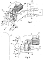
Figs. 2 and 3 are respectively a perspective view and a side view of the device, ofFigs. 1A and 1B , for the washing of the wheels of a vehicle in the more extensive washing installation; -
Fig. 4 is a view in longitudinal section of a rotating distributor included in the device for washing of.the wheels of a vehicle ofFigs. 1A, 1B ,2 and 3 ; -
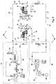
Fig. 5 is a diagram of a general supply circuit suitable for supplying the device for washing of the wheels of a vehicle ofFigs. 1A, 1B ,2 and 3 with water under pressure and a specific product suitable for the washing of the wheels; -
Fig. 6 is a diagram which shows, in succession, the various phases of a first cycle of washing of the wheels of a vehicle performed with the washing device ofFigs. 1A, 1B ,2 and 3 ; -
Fig. 7 is a diagram which shows, in succession, the various phases of a second cycle of washing of the wheels of a vehicle performed with the washing device ofFigs. 1A, 1B ,2 and 3 ; and -
Figs. 8A, 8B and 8C are photographic views of an example of the device for washing of the wheels of a vehicle ofFigs. 1A, 1B ,2 and 3 , mounted in a more general washing installation, and of some auxiliary devices of this washing device. - Referring to the drawings and in particular to
Figs. 1A and 1B , a device, in accordance with the present invention, for the washing of the wheels of a vehicle V is denoted as a whole by 10 and is part of a more extensive and complex installation, denoted by I, for the complete washing of the vehicle V. - The general features of the washing installation I are substantially known and therefore will not be described in detail.
- It is only pointed out that the installation I can be of various types, for example with single gantry, or with double gantry, i.e. made up of two gantries which move one in relation to the other during the cycle of washing of the vehicle V, or also comprising a higher number of mobile gantries.
- For clarity,
Figs. 1A and 1B show a typical portal structure organtry 20, mobile in relation to a vehicle V to be washed, which is included in a washing installation I and is essentially made up of two verticallateral uprights upper cross member 21 which connects above the twovertical uprights - More particularly the
gantry 20 is provided with own motor means, also of known features, suitable for driving a movement of translation of thesame gantry 20, and also comprises a plurality of rotary brushes, divided among vertical and horizontal brushes, denoted respectively by 22 and 23, which are associated with a system of nozzles for the emission and dispensing, on the bodywork of the vehicle V to be washed, of water under pressure and of specific emollient and/or detergent substances. - In use the
gantry 20 is provided for translating forwards and backwards, as denoted by a double arrow f1, along a rectilinear path in relation to the vehicle V, to be washed, which instead stays still, until completing an entire washing cycle, at the end of which the vehicle V is washed. - For example this rectilinear path can be defined by tracks or
guides 25, along which thegantry 20 moves in the two directions in order to wash the vehicle V. - The
gantry 20 is also usually equipped with a system of sensors, which are connected to a central unit of control of the general functioning of the washing installation I and are provided in order to perform several functions, for example detecting the effective position of the vehicle V, its side profile, and the distance of its two side panels from the twovertical uprights gantry 20, during the forward movement of thesame gantry 20 in relation to the vehicle V. - In particular this system of sensors includes a
sensor 14, installed in a lower area of a vertical upright 20a or 20b of thegantry 20, which has the specific function of detecting a wheel R of the vehicle V, during the translation of thegantry 20, in order to perform the cycle of washing of the vehicle V, as described better herein below. - Furthermore the
gantry 20 is associated with a system of drying, again of known features, having the function of drying the vehicle V, once washed, by blowing thereon a flow of air. - As shown in
Figs. 1A and 1B , adevice 10, in accordance with the present invention, for the washing of the wheels R of the vehicle V intended to be washed by means of the installation I, is usually installed on each one of the twovertical uprights gantry 20, and more precisely in a lower area of the upright at a height corresponding to that of the wheels R of the vehicle V to be washed. - In detail, as shown in
Figs. 2 and 3 , thewashing device 10, for washing the wheels R of the vehicle V, comprises: - a rotating
member 11, suitable for rotating around a respective axis ofrotation 11a and in turn comprising at least one first rotatingarm 12 for the dispensing of one or more jets of water at high pressure denoted by HP (high pressure) by means of one ormore nozzles 13 provided on the samefirst arm 11; and a second rotatingarm 16, for the dispensing of a specific chemical product P for the washing of the wheels of the vehicle V, by means of one ormore nozzles 17 provided on the samesecond arm 16; - an
electric motor assembly 18, suitable for driving the rotation of the rotatingmember 11 around the respective axis ofrotation 11a; - a general supply circuit, denoted as a whole by 30, for supplying the water under pressure HP and the specific product P to the rotating
member 11, and - a rotating distributor or joint 19 for connecting the
general supply circuit 30 to the rotatingmember 11 and distributing to the latter the water under pressure HP and the specific product P. - The rotating
member 11 of thewashing device 10 is composed of a central part, in turn constituted by arotating body 19a of the rotatingdistributor 19, and, in the preferred embodiment of the invention described here, of three radial arms, which are attached to the base on therotating body 19a and extend radially from the latter, as shown inFigs. 2 and 3 . - These three arms are angularly distanced in a uniform manner, i.e. positioned at approximately 120° one from the other, around the
axis 11a, and two arms thereof, denoted by 12, carry each one twonozzles 13 for the emission of the jets of water at high pressure HP, and a third arm, denoted by 16, carries anozzle 17 for the dispensing of the specific product P. - Both the
nozzles 13 and thenozzles 17 are mounted in the end zone, distant from the axis ofrotation 11 a, of therespective arms - It is in any case clear that any other arrangement and number both of the arms and of the nozzles for the emission of the water under pressure HP and the dispensing of the product P, with respect to what is described, are possible and are always to be considered within the present invention.
- A
circular protection screen 24, schematised with a dotted and dashed line inFig. 3 , can be attached to therotating body 19a of thedistributor 19 so as to rotate integrally therewith, with the purpose of protecting in use thearms member 11. - The
electric motor assembly 18, used to rotate the rotatingmember 11 around the respective axis ofrotation 11 a, is of known features and in particular is made up of anelectric motor 18a coupled with areducer 18b. - According to an essential feature of the present invention, the
general supply circuit 30 is in turn divided into a firsthydraulic supply circuit 31 provided in order to supply the water under pressure HP to the washing device forwheels 10, and into a secondhydraulic supply circuit 32 provided for supplying the specific product P to thesame washing device 10, wherein these first andsecond supply circuits arms 12, of the rotatingmember 11, carrying the nozzle or thenozzles 13 for the emission of the jets of water at high pressure HP, and the rotating arm orarms 16, of the rotatingmember 11, carrying the nozzle or thenozzles 17 for the dispensing of the specific product P. - Therefore, thanks to this specific configuration of the
supply circuit 30 wherein the twocircuits - The rotating
distributor 19 is also such as to create this distinct separation between the water under pressure HP and the specific product P which are supplied to the rotatingmember 11 in order to wash the wheel R, and in particular, with reference toFig. 4 , comprises: - an external
fixed body 19b; - a central
rotating body 19a, which extends partially in said fixedexternal body 19b along theaxis 11a of the rotatingmember 11, whereof it constitutes the central hub or part, wherein thiscentral body 19a is suitable for rotating in relation to the fixedbody 19b and around thisaxis 11a in response to the command of themotor assembly 18; - a first inlet opening 19c formed along the
axis 11a of the centralrotating body 19a and suitable for receiving the water under pressure HP from therespective supply circuit 31; - a first and a second outlet opening 19d, whereof only one is shown in
Fig. 4 , formed on the periphery of the centralrotating body 19a and each one suitable for supplying to acorresponding arm 12 the water under pressure HP coming from thefirst inlet opening 19c; - a second inlet opening 19e formed on the periphery of the fixed
body 19b and suitable for receiving the specific product P from therespective supply circuit 32, and - a third outlet opening 19f formed on the periphery of the central
rotating body 19a and suitable for supplying to thecorresponding arm 16 the specific product P coming from the second inlet opening 19e. - A system of
gaskets 19g ensures the seal between thefixed body 19b and the rotatingcentral body 19a during their relative rotation, so as to prevent the specific product P, which flows through the rotatingdistributor 19 between the inlet opening 19e and theoutlet opening 19f, from being able to seep to the outside. - As can be seen from
Fig. 4 , in the rotatingdistributor 19 the water under pressure HP and the specific product P are conveyed and distributed along respective conduits, denoted by 19i and 19h, which are totally separate one from the other and do not share any section in common. - The diagram of
Fig. 5 shows as a whole thesupply system 30, including the twosupply circuits distributor 19 and therefore also to the rotatingmember 11 of twodistinct washing assemblies 10, wholly identical one to the other, in accordance with the present invention, each one installed on a correspondingvertical upright gantry 20 of the installation I, in order to wash the wheels R positioned on the two opposite side panels of the vehicle V. - Therefore a
first washing device 10 is supplied with water under pressure HP and with the specific product P by means of respective supply lines L1 and L2, reciprocally separate and distinct, defined respectively by thesupply circuit 31 and by thesupply circuit 32. - Similarly the
second washing device 10 is supplied with the water under pressure HP and with the specific product P by means of corresponding supply lines L1' and L2', reciprocally separate and distinct, defined respectively by asupply circuit 31 and by asupply circuit 32, identical to those which supply thefirst washing device 10. - Moreover the
supply system 30 comprises a pressure assembly, generally denoted by 33, common to twowashing assemblies 10, of known features and therefore not described in detail, which has the function of generating a flow of water under pressure HP suitable for supplying thesupply circuit 31 of eachwashing assembly 10. - It is made clear only that
pressure assembly 33 is provided for receiving the water from the external network RE and compressing it by means of apump 34 for generating this flow of water under pressure HP. - This
pressure assembly 33 can be associated with an emollient assembly, denoted in general by 36 and also of known features, in order to supply an emollient substance EM to be mixed with the water under pressure HP generated by thepressure assembly 33. - Moreover the
supply system 30 comprises a product assembly, generally denoted by 37, common to twowashing assemblies 10, which contains a reserve of the specific chemical product P to be used for the washing of the wheels R of the vehicle V and has the function of generating a flow of the same product P intended to supply each one of the twowashing assemblies 10, via therespective supply circuits 32. - This
product assembly 37 is also of known features, and therefore will not be described in detail, only showing inFig. 5 the unified symbols of the parts and of the components whereof it is constituted. - It is made clear only that the
product assembly 37 comprises ametering pump 38, with variable piston displacement, suitable for metering the quantity of the specific product P to be dispensed during the cycle of washing of the wheels, which can be associated with other auxiliary devices, as well known to persons skilled in the art, such as for example a source, denoted by 39, of compressed air, having the function of co-operating with themetering pump 38 in order to generate the flow of the specific product P towards the twowashing devices 10. - Naturally the
system 30 comprises also a system of valves, as shown by the relative symbols inFig. 5 , which are appropriately located along the conduits and the pipes of thissystem 30 for the purpose of controlling the flow of the water under pressure HP and of the specific product P. - In the use of the
device 10, the central electronic unit UC (Fig. 2 ), for example made up of a PLC (programmable logic controller), which governs the general functioning of the washing installation I and of thegantry 20 whereof thewashing assembly 10 is part, controls, as part of an overall cycle of washing of the vehicle V, the performance, by thedevice 10, of the specific washing cycle aimed at washing the wheels R of the vehicle V. - In particular, according to the methods established by this overall washing cycle, the
gantry 20, moving forwards in relation to the vehicle V to be washed, detects by means of thesensor 14 the position of a first wheel R or pair of wheels R of the vehicle V. - Subsequently, when, after a further forward movement of the
gantry 20, thewashing device 10 is in front of the wheel R previously detected, thegantry 20 stops immediately. - At this point, therefore with the
gantry 20 at a standstill, the control unit UC activates, in successive phases and according to the methods of the cycle which has been established for the washing of the wheel, theproduct assembly 37 and thepressure assembly 33. - In this way the specific product P and the water under pressure HP are supplied, by means of the
respective supply circuits distributor 19, to therespective arms member 11 of thewashing device 10, as indicated by arrows inFigs. 4 and5 . - Therefore, during the supply to the rotating
member 11, the specific product P and the water under pressure HP never flow, even in different times, along sections of conduits or pipes in common, so as to avoid any possibility of pollution between these two fluids. - At the same time the
motor assembly 18 drives the rotation of the rotatingmember 11. - Therefore the
member 11, rotating, dispenses, by means of thenozzles 17 provided on thearm 16, the specific product P, and emits, by means of thenozzles 13 provided on thearms 12, a plurality of jets of water under pressure HP, in the direction of the wheel R to be washed. - In particular, both the dispensing of the water under pressure HP and that of the specific product P can be performed, according to a programmed sequence which depends on the specific washing cycle adopted, with the rotating
member 11 which rotates in a first time in one direction of rotation and then in a second time in the opposite direction of rotation, as indicated by arrows f2 and f2' in the drawings. - In order to provide information as complete as possible on the features and the various aspects of the present invention, a description will now be given, with reference to
Figs. 6 and7 and supposing for simplicity that the installation I is of the type with mono or single gantry, of some innovative washing cycles, denoted by A and B, which can be performed by means of thenew device 10, described previously, for the washing of the wheels R of a vehicle V. - A description will therefore be given, for each washing cycle A, B, of the various single operations, whereof the cycle is constituted, which are performed during the forward and backward passes of the
gantry 20, in turn equipped with twodistinct washing devices 10 each one installed on a respective vertical upright of thegantry 20. -
- detecting, by means of the
appropriate sensor 14, of the front wheels R' of the vehicle V; -
- dispensing, by means of the rotating
member 11 of thewashing devices 10, of the specific product P on the front wheels of the vehicle, with programmed reverse of the direction of rotation of this rotatingmember 11; - wait for a predetermined time in order to allow the dispensed specific product P to react;
- dispensing, by means of the rotating
member 11 of thewashing devices 10, of jets of water under pressure HP on the front wheels R', with programmed reverse of the direction of rotation of the rotatingmember 11; -
- detecting, by means of the
appropriate sensor 14, of the pair of rear wheels R" of the vehicle V; -
- dispensing, by means of the rotating
member 11 of thewashing devices 10, of the specific product P on the rear wheels R" of the vehicle V, with programmed reverse of the direction of rotation of the rotatingmember 11 of thedevice 10; - wait for a predetermined time in order to allow the specific product dispensed on the rear wheels R" to react;
- dispensing, by means of the rotating
member 11 of thewashing devices 10, of jets of water under pressure HP on the rear wheels R", with programmed reverse of the direction of rotation of the rotatingmember 11. -
- detecting, by means of the
appropriate sensor 14, of the front wheels R' of the vehicle V; -
- dispensing, by means of the rotating
member 11 of thewashing devices 10, of the specific product P on the front wheels R' of the vehicle, with programmed reverse of the direction of rotation of the rotatingmember 11; -
- detecting, by means of the
appropriate sensor 14, of the pair of rear wheels R" of the vehicle V; -
- dispensing, by means of the rotating
member 11 of thewashing devices 10, of the specific product P on the rear wheels R" of the vehicle V, with reverse of the direction of rotation of the rotatingmember 11 of thedevice 10; - further forward movement of the
gantry 20 up to the end of the forward pass. -
- search for the rear wheels R" of the vehicle V detected during the previous forward pass of the
gantry 20; -
- dispensing, by means of the rotating
member 11 of thewashing devices 10, of jets of water under pressure HP on the rear wheels R", with programmed reverse of the direction of rotation of the rotatingmember 11; - search for the rear wheels R' of the vehicle V detected during the previous forward pass of the
gantry 20; -
- dispensing of jets of water under pressure HP on the front wheels R' of the vehicle V, with programmed reverse of the direction of rotation of the rotating
member 11. - The cycles A and B, described previously, for the washing of the wheels of a vehicle V, are normally part of a more complex and varied cycle, for the complete washing of the vehicle V, which is performed in the washing installation I in which the
washing device 10 is integrated, and which obviously depends on the features and on the specific type of this installation I, it being possible for example for the latter to be of the mono-gantry type, or with double gantry or also to comprise a higher number of gantries mobile one in relation to the other. - Therefore the possibilities and the combinations which can be achieved of cycles for the complete washing of the vehicle V, including the use of the
device 10, are multiple. - It is in any case important that there is no interference between the various phases of the cycle of washing of the wheels of the vehicle V, performed by means of the
device 10 in the forms A and B described previously, and the various other phases which define the complete cycle of washing of the vehicle V which is performed in the installation I wherein thewashing device 10 for wheels is included. - As is known, these other phases can include the dispensing of emollient/detergent substances, the dispensing of jets of water at high pressure on the side panels and on the other parts of the bodywork of the vehicle, the brushing of the bodywork of the vehicle by means of the vertical and horizontal rotary brushes with which the installation is equipped, and other phases again well known to the persons skilled in the art.
- Moreover, even if the cycles of washing A and B described previously provide, at the start, an action on the front wheels of the vehicle and, subsequently, on the rear wheels, it is obvious that this sequence can be reversed, and that therefore the washing cycles can be performed starting from the rear wheels to then continue with the front ones, according to the specific features and functions of the washing installation I wherein these cycles of washing of the wheels of a vehicle are performed.
- For even more complete information the photographic views of
Figs. 8A, 8B show an effective example of thedevice 10 for washing of the wheels of a vehicle according to the present invention, installed in amobile gantry 20 of a washing installation I, while the photographic view ofFig. 8C shows the area of theproduct assembly 37 and in particular of therespective metering pump 38, suitable for metering the quantity of the specific product P to be dispensed during the cycle of washing of the wheels R. - It is therefore clear, from what is described with respect both to the features that qualify the washing device for washing the wheels of a vehicle, and the cycles of washing of a wheel which can be performed with this device, that the present invention fully achieves the objects that had been set, and more particularly provides a new device for washing the wheels of a vehicle which offers significant improvements and better performances with respect to the devices currently known and in use.
- In particular the washing device of the invention has a non-complex construction, made up of a few simple parts, characterised by the absence of valves or similar devices, for the control of the flow of the water under pressure or of the specific chemical product, in the various arms of the rotating member included in this device.
- Moreover, thanks to the presence in this device of dispensing arms rotating in the two directions according to a programmed sequence, both the specific product and the water under pressure are dispensed in a uniform and effective manner on the various parts of the wheel, and above all on the respective rim, with positive effects on the final quality of the washing of the wheel.
Claims (10)
- Washing device (10) for washing the wheels of a vehicle (V) in an installation (I, 20) for the washing of vehicles, comprising:- a rotating member (11) comprising at least one first rotating arm (12) for dispensing water under pressure (HP) on a wheel (R) of the vehicle (V) by means of one or more nozzles (13) provided on said first rotating arm (12), and at least one second rotating arm (16) for dispensing, on the same wheel (R), a specific chemical product (P) for the washing of the wheels of the vehicle, by means of one or more nozzles (17) provided on said second rotating arm (16);- an electric motor assembly (18, 18a, 18b), for driving the rotation of said rotating member (11);- a first hydraulic supply circuit (31) for supplying the water under pressure (HP) to said rotating member (11, 12);- a second hydraulic supply circuit (32) for supplying said specific product (P) to said rotating member (11, 16), and- a rotating distributor (19) for connecting said first (31) and said second (32) supply circuits to said rotating member (11) and distributing the water under pressure (HP) and the specific product (P) respectively to said first rotating arm (12) and to said second rotating arm (16);wherein said first and said second supply circuits (31, 32) are reciprocally distinct without having any conduit in common and are configured, together with said rotating distributor (19), in such a way as to supply and distribute, one separately from the other, the water under pressure (HP) and the specific chemical product (P), respectively to said first (12) and to said second (16) rotating arm of the rotating member (11).
- Device for washing (10) the wheels of a vehicle according to claim 1, wherein said rotating arms (12, 16), comprised in said rotating member (11), consist of two rotating arms (12) for the dispensing of water under pressure (HP) on the wheel (R) of the vehicle (V), and of a rotating arm (16) for the dispensing, on the same wheel (R), of the specific chemical product (P) for washing the wheels of the vehicle.
- Device for washing (10) the wheels of a vehicle according to claim 1 or 2, wherein said rotating distributor (19) in turn comprises:- a fixed body (19b);- a rotating body (19a) suitable for rotating, relatively to said fixed body (19b), around an axis of rotation (11a) corresponding to the axis of rotation of said rotating member (11);- at least one first inlet opening (19c) formed along the axis (11a) of said rotating body (19a) and suitable for receiving the water under pressure (HP) from the respective supply circuit (31);- at least one first outlet opening (19d) formed in said rotating body (19a) and suitable for supplying to a corresponding arm (12) the water under pressure (HP) coming from said first inlet opening (19c);- at least one second inlet opening (19e) formed in said fixed body (19b) and suitable for receiving said specific product (P) from the respective supply circuit (32), and- at least one second outlet opening (19f) formed in said rotating body (19a) and suitable for supplying to the corresponding arm (16) the specific product (P) coming from said second inlet opening (19e),wherein the two conduits (19i, 19h) between said first inlet opening (19c) and said first outlet opening (19d) and between said second inlet opening (19e) and said second outlet opening (19f), for the flow through said rotating distributor (19) respectively of the water under pressure (HP) and of the specific product (P), are distinct and separate one from the other.
- Device for washing the wheels of a vehicle (V) according to any one of the preceding claims, wherein said arms (12, 16) extend radially from a rotating body (19a) of said rotating distributor (19) and said nozzles (13, 17) are directed in a direction substantially perpendicular to the respective arms (12, 16).
- Device for washing the wheels of a vehicle (V) according to any one of the preceding claims, wherein said rotating member (11) is suitable for rotating in the two directions (f2, f2') according to a programmed sequence in order to dispense the water under pressure (HP) and the specific product (P) on the wheel to be washed.
- Device for washing the wheels of a vehicle (V) according to any one of the preceding claims, associated with a product assembly (37) in order to produce a flow of said specific product (P) in said second hydraulic supply circuit (32), wherein said product assembly (37) comprises a compressed air source suitable for activating said flow.
- Installation (I) for the washing of motor vehicles comprising a device, according to any one of the preceding claims, for the washing of the wheels of a vehicle (V).
- Installation (I) for the washing of motor vehicles according to claim 7, comprising:- at least one mobile gantry (20);- a device (10) for washing the wheels of a vehicle (V), according to any one of claims 1 to 6, mounted on each of the two vertical uprights (20a, 20b) of said mobile gantry (20);- a common pressure assembly (36) for producing a flow of said water under pressure (HP) in both first hydraulic supply circuits (31) of the two washing devices mounted on the mobile gantry (20), and- a common product assembly (37) for producing a flow of said specific product (P) in both second hydraulic supply circuits (32) of the two washing devices mounted on the mobile gantry (20).
- Cycle of washing (A) of the wheels (R) of a vehicle (V) performed with a wheel washing device (10) included in an installation (I) for washing vehicles and having:- a rotating member (11) comprising at least one first rotating arm (12) for dispensing water under pressure (HP) on a wheel (R) of the vehicle (V), and at least one second rotating arm (16) for dispensing, on the same wheel (R), a specific chemical product (P) for the washing of the wheels of the vehicle;- a first hydraulic supply circuit (31) for supplying the water under pressure (HP) to said rotating member (11, 12);- a second hydraulic supply circuit (32) for supplying said specific product (P) to said rotating member (11, 16), and- a rotating distributor (19) for connecting said first (31) and said second (32) supply circuits to said rotating member (11) and distributing the water under pressure (HP) and the specific product (P) respectively to said first rotating arm (12) and to said second rotating arm (16);wherein said first and said second supply circuits (31, 32) are reciprocally distinct without having any conduit in common and are configured, together with said rotating distributor (19), in such a way as to supply and distribute, one separately from the other, the water under pressure (HP) and the specific chemical product (P), respectively to said first (12) and to said second (16) rotating arm of the rotating member (11),
the wheel washing cycle comprising the following steps:during a forward pass of a gantry (20) of the washing installation (I),- moving forwards (a-1) the gantry (20) and detecting, during this forward movement, at least one first wheel (R) of a first pair of wheels of the vehicle (V) to be washed;- stopping (a-2) the gantry (20) in front of the first wheel (R), previously detected;- dispensing (a-2) on the first wheel a specific product (P) suitable for washing it, reversing (f2, f2') in a programmed manner the direction of rotation of the dispensing rotating member (11) of the washing device (10);- dispensing (a-2), after a predetermined time such as to allow the dispensed specific product (P) to react, jets of water under pressure (HP) on the wheel, reversing in a programmed manner the direction of rotation of the rotating member (11);- further moving forwards (a-3) the gantry and detecting during this further forward movement at least one second wheel (R) of the remaining wheels of the vehicle to be washed;- stopping (a-4) the gantry (20) in front of the second wheel (R), previously detected;- dispensing (a-4) on the second wheel a specific product (P) suitable for washing it, reversing (f2, f2') in a programmed manner the direction of rotation of the dispensing rotating member (11) of the washing device (10);- dispensing, after a predetermined time such as to allow the dispensed specific product (P) to react, jets of water under pressure (HP) on the second wheel, reversing in a programmed manner the direction of rotation of the rotating member (11). - Cycle of washing (B) of the wheels (R) of a vehicle (V) performed with a wheel washing device (10) included in an installation (I) for washing vehicles and having:- a rotating member (11) comprising at least one first rotating arm (12) for dispensing water under pressure (HP) on a wheel (R) of the vehicle (V), and at least one second rotating arm (16) for dispensing, on the same wheel (R), a specific chemical product (P) for the washing of the wheels of the vehicle;- a first hydraulic supply circuit (31) for supplying the water under pressure (HP) to said rotating member (11, 12);- a second hydraulic supply circuit (32) for supplying said specific product (P) to said rotating member (11, 16), and- a rotating distributor (19) for connecting said first (31) and said second (32) supply circuits to said rotating member (11) and distributing the water under pressure (HP) and the specific product (P) respectively to said first rotating arm (12) and to said second rotating arm (16);wherein said first and said second supply circuits (31, 32) are reciprocally distinct without having any conduit in common and are configured, together with said rotating distributor (19), in such a way as to supply and distribute, one separately from the other, the water under pressure (HP) and the specific chemical product (P), respectively to said first (12) and to said second (16) rotating arm of the rotating member (11),
the wheel washing cycle comprising the following steps:during a forward pass of a gantry (20) of the washing installation (I),- moving forwards (b-1) the gantry (20) and detecting, during this forward movement, at least one first wheel (R') of a first pair of wheels of the vehicle (V) to be washed;- stopping (b-2) the gantry (20) in front of the first wheel (R'), previously detected;- dispensing (b-2) on the first wheel a specific product (P) suitable for washing it, reversing (f2, f2') in a programmed manner the direction of rotation of the dispensing rotating member (11) of the washing device (10);- further moving forwards (b-3) the gantry and detecting during this further forward movement at least one second wheel (R") of the remaining wheels of the vehicle to be washed;- stopping (b-4) the gantry (20) in front of the second wheel (R"), previously detected;- dispensing (b-4) on the second wheel (R") the specific product (P) suitable for washing it, reversing (f2, f2') in a programmed manner the direction of rotation of the dispensing rotating member (11) of the washing device (10);- completing (b-5) the forward pass of the gantry (20);- during a subsequent backward pass of the gantry (20) of the washing installation (I)- initially moving forwards (b-6) the gantry (20) and stopping it in front of the second wheel (R") detected during the previous forward pass;- dispensing (b-4) jets of water under pressure (HP) on the second wheel (R"), reversing (f2, f2') in a programmed manner the direction of rotation of the rotating member (11);- further moving forwards the gantry (20) and stopping it (b-7) in front of the first wheel (R') detected during the previous forward pass;- dispensing (b-7) jets of water under pressure (HP) on the second wheel (R"), reversing (f2, f2') in a programmed manner the direction of rotation of the rotating member (11).
Applications Claiming Priority (2)
| Application Number | Priority Date | Filing Date | Title |
|---|---|---|---|
| IT001997 IT1408580B1 (en) | 2011-11-03 | 2011-11-03 | IMPROVED IMPROVEMENT FOR WASHING WHEELS OF A VEHICLE IN A VEHICLE WASHING SYSTEM, AND RESPECTING NEW WASH CYCLES MADE WITH SUCH A DEVICE |
| PCT/EP2012/071626 WO2013064574A1 (en) | 2011-11-03 | 2012-10-31 | Improved device for the washing of the wheels of a vehicle in a vehicles washing installation and respective new washing cycles performed with this device |
Publications (2)
| Publication Number | Publication Date |
|---|---|
| EP2773541A1 EP2773541A1 (en) | 2014-09-10 |
| EP2773541B1 true EP2773541B1 (en) | 2016-08-17 |
Family
ID=45757086
Family Applications (1)
| Application Number | Title | Priority Date | Filing Date |
|---|---|---|---|
| EP12790451.4A Active EP2773541B1 (en) | 2011-11-03 | 2012-10-31 | Improved device for the washing of the wheels of a vehicle in a vehicles washing installation and respective new washing cycles performed with this device |
Country Status (5)
| Country | Link |
|---|---|
| EP (1) | EP2773541B1 (en) |
| CN (1) | CN104125900A (en) |
| ES (1) | ES2603654T3 (en) |
| IT (1) | IT1408580B1 (en) |
| WO (1) | WO2013064574A1 (en) |
Cited By (2)
| Publication number | Priority date | Publication date | Assignee | Title |
|---|---|---|---|---|
| DE102017111300A1 (en) | 2017-05-23 | 2018-11-29 | Washtec Holding Gmbh | Oscillating vehicle treatment device |
| WO2019042665A1 (en) * | 2017-08-28 | 2019-03-07 | Washtec Holding Gmbh | TURNING PROCESS FOR TWO MEDIA WITH A PRESSURE-CONTROLLED PASSAGE |
Families Citing this family (12)
| Publication number | Priority date | Publication date | Assignee | Title |
|---|---|---|---|---|
| DE102014117167A1 (en) * | 2014-11-24 | 2016-05-25 | Alfred Kärcher Gmbh & Co. Kg | Gantry washing system and method for cleaning a motor vehicle |
| DE102015002531B3 (en) * | 2015-03-02 | 2016-06-16 | Fresenius Medical Care Deutschland Gmbh | Method for cleaning a multidirectional wheel |
| JP6515845B2 (en) * | 2016-03-16 | 2019-05-22 | 株式会社ダイフク | Car wash machine and car wash method |
| CN106080529B (en) * | 2016-07-07 | 2018-07-13 | 李东波 | Hub cleaning mechanism |
| DE102016122802A1 (en) | 2016-11-25 | 2018-05-30 | Washtec Holding Gmbh | Method for operating a vehicle washing system and vehicle washing system |
| CN106627510B (en) * | 2017-01-17 | 2018-12-28 | 绍兴顶多纺织有限公司 | A kind of intelligent automobile wheel hub cleaning robot |
| CN107813839A (en) * | 2017-08-14 | 2018-03-20 | 金鹰重型工程机械有限公司 | A kind of power decentralized shaped steel rail inspection car |
| CN109515392B (en) * | 2018-11-09 | 2021-08-27 | 广西大学 | Automatic engineering vehicle tire cleaning device with visual detection function |
| CN109895749B (en) * | 2019-04-26 | 2021-07-16 | 禹海平 | Be used for new energy automobile wheel belt cleaning device |
| CN111959453A (en) * | 2020-09-14 | 2020-11-20 | 北京魔鬼鱼科技有限公司 | Car washer for washing car |
| CN113911077B (en) * | 2021-09-15 | 2023-09-08 | 北京魔鬼鱼科技有限公司 | Intelligent car washing device and system |
| CN216636423U (en) * | 2021-11-11 | 2022-05-31 | 北京魔鬼鱼科技有限公司 | Integrated hub cleaning device |
Citations (13)
| Publication number | Priority date | Publication date | Assignee | Title |
|---|---|---|---|---|
| US3496908A (en) | 1967-05-15 | 1970-02-24 | Eugene P Bernardi | Automatic vehicle cleansing device |
| US4716916A (en) | 1985-12-23 | 1988-01-05 | Grace-Lee Products, Inc. | Vehicle cleansing |
| DE3844662A1 (en) | 1988-11-11 | 1990-05-23 | Ott Maschinentechnik | SECURING A HOLLOW SHAFT BEARING |
| FR2660611A1 (en) | 1990-04-05 | 1991-10-11 | Ns Ferrum Sa | Device for washing the wheels and the bottom of the body of a vehicle |
| DE4103376C1 (en) | 1991-02-05 | 1992-08-06 | Ott Maschinentechnik Gmbh, 8960 Kempten, De | |
| DE9414483U1 (en) | 1994-09-07 | 1995-02-23 | Mosmatic Ag, Necker | Ceiling gyroscope for high-pressure washing devices |
| DE19951182A1 (en) | 1999-05-03 | 2000-11-09 | Christ Otto Ag | Wheel rim cleaning device, especially for use in car wash, has brush executing oscillating movement in direction of wheel rims during washing process, and with bristles of brush acting on rim during withdrawal movement |
| WO2002030575A1 (en) | 2000-10-10 | 2002-04-18 | Chase Industries, Inc. | Liquid spray apparatus, system and methods |
| US20070068554A1 (en) | 2005-09-23 | 2007-03-29 | Vq, Inc. | Car wash tire applicator and related method |
| CN101126475A (en) | 2007-09-07 | 2008-02-20 | 李继锁 | High pressure swivel joint |
| CN101214813A (en) | 2008-01-07 | 2008-07-09 | 黄岳良 | Surrounding type non-contact wiping-free car washing machine |
| DE102009008423A1 (en) | 2009-02-11 | 2010-08-12 | Mosmatic Ag | Angular swivel joint, has central sleeve arranged between housings of hollow shaft in area of separating joint, where sleeve is supported and sealed at housing-sided front sides by sealing packets of separating joint |
| EP2243672A1 (en) | 2009-04-24 | 2010-10-27 | Aquarama Srl | Dual-gantry vehicle washing system and a vehicle washing process |
Family Cites Families (2)
| Publication number | Priority date | Publication date | Assignee | Title |
|---|---|---|---|---|
| US6277207B1 (en) * | 1999-08-02 | 2001-08-21 | Mark Vii Equipment, Inc. | Control system for vehicle washing system |
| CN2900274Y (en) * | 2005-12-09 | 2007-05-16 | 任良福 | Automatic car washing device |
-
2011
- 2011-11-03 IT IT001997 patent/IT1408580B1/en active
-
2012
- 2012-10-31 ES ES12790451.4T patent/ES2603654T3/en active Active
- 2012-10-31 CN CN201280053997.6A patent/CN104125900A/en active Pending
- 2012-10-31 EP EP12790451.4A patent/EP2773541B1/en active Active
- 2012-10-31 WO PCT/EP2012/071626 patent/WO2013064574A1/en not_active Ceased
Patent Citations (13)
| Publication number | Priority date | Publication date | Assignee | Title |
|---|---|---|---|---|
| US3496908A (en) | 1967-05-15 | 1970-02-24 | Eugene P Bernardi | Automatic vehicle cleansing device |
| US4716916A (en) | 1985-12-23 | 1988-01-05 | Grace-Lee Products, Inc. | Vehicle cleansing |
| DE3844662A1 (en) | 1988-11-11 | 1990-05-23 | Ott Maschinentechnik | SECURING A HOLLOW SHAFT BEARING |
| FR2660611A1 (en) | 1990-04-05 | 1991-10-11 | Ns Ferrum Sa | Device for washing the wheels and the bottom of the body of a vehicle |
| DE4103376C1 (en) | 1991-02-05 | 1992-08-06 | Ott Maschinentechnik Gmbh, 8960 Kempten, De | |
| DE9414483U1 (en) | 1994-09-07 | 1995-02-23 | Mosmatic Ag, Necker | Ceiling gyroscope for high-pressure washing devices |
| DE19951182A1 (en) | 1999-05-03 | 2000-11-09 | Christ Otto Ag | Wheel rim cleaning device, especially for use in car wash, has brush executing oscillating movement in direction of wheel rims during washing process, and with bristles of brush acting on rim during withdrawal movement |
| WO2002030575A1 (en) | 2000-10-10 | 2002-04-18 | Chase Industries, Inc. | Liquid spray apparatus, system and methods |
| US20070068554A1 (en) | 2005-09-23 | 2007-03-29 | Vq, Inc. | Car wash tire applicator and related method |
| CN101126475A (en) | 2007-09-07 | 2008-02-20 | 李继锁 | High pressure swivel joint |
| CN101214813A (en) | 2008-01-07 | 2008-07-09 | 黄岳良 | Surrounding type non-contact wiping-free car washing machine |
| DE102009008423A1 (en) | 2009-02-11 | 2010-08-12 | Mosmatic Ag | Angular swivel joint, has central sleeve arranged between housings of hollow shaft in area of separating joint, where sleeve is supported and sealed at housing-sided front sides by sealing packets of separating joint |
| EP2243672A1 (en) | 2009-04-24 | 2010-10-27 | Aquarama Srl | Dual-gantry vehicle washing system and a vehicle washing process |
Cited By (2)
| Publication number | Priority date | Publication date | Assignee | Title |
|---|---|---|---|---|
| DE102017111300A1 (en) | 2017-05-23 | 2018-11-29 | Washtec Holding Gmbh | Oscillating vehicle treatment device |
| WO2019042665A1 (en) * | 2017-08-28 | 2019-03-07 | Washtec Holding Gmbh | TURNING PROCESS FOR TWO MEDIA WITH A PRESSURE-CONTROLLED PASSAGE |
Also Published As
| Publication number | Publication date |
|---|---|
| ITMI20111997A1 (en) | 2013-05-04 |
| WO2013064574A1 (en) | 2013-05-10 |
| IT1408580B1 (en) | 2014-06-27 |
| CN104125900A (en) | 2014-10-29 |
| EP2773541A1 (en) | 2014-09-10 |
| ES2603654T3 (en) | 2017-02-28 |
Similar Documents
| Publication | Publication Date | Title |
|---|---|---|
| EP2773541A1 (en) | Improved device for the washing of the wheels of a vehicle in a vehicles washing installation and respective new washing cycles performed with this device | |
| CN104523208B (en) | Spray arm device and dish-washing machine | |
| US20110271988A1 (en) | Dual Pressure Spray Arm Assembly with Diverter Valve | |
| CN203402146U (en) | Windscreen wiper framework used for installing windscreen wiper blade and windscreen cleaning system | |
| CN101214813B (en) | Surrounding type non-contact wiping-free car washing machine | |
| RU2450868C2 (en) | Universal sprayer and method of its operation | |
| US20100122714A1 (en) | Method of Operating a Wheel Washing Assembly | |
| JP6831150B1 (en) | washing machine | |
| CN102292163A (en) | Coating product spraygun and method for resupplying coating product to such a spraygun | |
| US6896010B2 (en) | Method and device for filling a paint reservoir in an automated painting installation | |
| WO2012159936A1 (en) | Improved double gantry type carwash installation and washing cycle associated to this new installation | |
| CN109017705A (en) | A kind of rotary carwash robot | |
| CN203235727U (en) | Bottle spraying washing device | |
| CN209208726U (en) | A kind of car washer liftable injection apparatus | |
| US20180093646A1 (en) | Washing equipment for a vehicle | |
| KR102406859B1 (en) | Pipe Line Cleaning System Using High Pressure Press-Fitting and Vacuum Suction of Washing Water | |
| CN106245566A (en) | A kind of novel pavement cleaning Vehicle rotating type high-pressure spraying-cleaning device | |
| CN103966966A (en) | Cleaning and sweeping vehicle rotary type high-pressure cleaning device | |
| CN107457117A (en) | A kind of air outlet spraying equipment and its method | |
| CN203821286U (en) | Rotary high-pressure cleaning device for cleaning sweeper truck | |
| CN210523293U (en) | Rear-flushing self-rotating flushing device of expanding machine | |
| CN207899837U (en) | Bottle cleaning machine | |
| CN207931687U (en) | A kind of reciprocating automatic car washing machine | |
| EP1968829B1 (en) | Automatic vehicle washing unit and process | |
| CN214112503U (en) | Automatic washing unit of green building construction |
Legal Events
| Date | Code | Title | Description |
|---|---|---|---|
| PUAI | Public reference made under article 153(3) epc to a published international application that has entered the european phase |
Free format text: ORIGINAL CODE: 0009012 |
|
| 17P | Request for examination filed |
Effective date: 20140430 |
|
| AK | Designated contracting states |
Kind code of ref document: A1 Designated state(s): AL AT BE BG CH CY CZ DE DK EE ES FI FR GB GR HR HU IE IS IT LI LT LU LV MC MK MT NL NO PL PT RO RS SE SI SK SM TR |
|
| DAX | Request for extension of the european patent (deleted) | ||
| GRAP | Despatch of communication of intention to grant a patent |
Free format text: ORIGINAL CODE: EPIDOSNIGR1 |
|
| INTG | Intention to grant announced |
Effective date: 20160329 |
|
| GRAS | Grant fee paid |
Free format text: ORIGINAL CODE: EPIDOSNIGR3 |
|
| GRAA | (expected) grant |
Free format text: ORIGINAL CODE: 0009210 |
|
| AK | Designated contracting states |
Kind code of ref document: B1 Designated state(s): AL AT BE BG CH CY CZ DE DK EE ES FI FR GB GR HR HU IE IS IT LI LT LU LV MC MK MT NL NO PL PT RO RS SE SI SK SM TR |
|
| REG | Reference to a national code |
Ref country code: GB Ref legal event code: FG4D |
|
| REG | Reference to a national code |
Ref country code: CH Ref legal event code: EP |
|
| REG | Reference to a national code |
Ref country code: IE Ref legal event code: FG4D |
|
| REG | Reference to a national code |
Ref country code: AT Ref legal event code: REF Ref document number: 820727 Country of ref document: AT Kind code of ref document: T Effective date: 20160915 |
|
| REG | Reference to a national code |
Ref country code: DE Ref legal event code: R096 Ref document number: 602012021969 Country of ref document: DE |
|
| REG | Reference to a national code |
Ref country code: NL Ref legal event code: MP Effective date: 20160817 |
|
| REG | Reference to a national code |
Ref country code: LT Ref legal event code: MG4D |
|
| REG | Reference to a national code |
Ref country code: AT Ref legal event code: MK05 Ref document number: 820727 Country of ref document: AT Kind code of ref document: T Effective date: 20160817 |
|
| REG | Reference to a national code |
Ref country code: FR Ref legal event code: PLFP Year of fee payment: 5 |
|
| PG25 | Lapsed in a contracting state [announced via postgrant information from national office to epo] |
Ref country code: RS Free format text: LAPSE BECAUSE OF FAILURE TO SUBMIT A TRANSLATION OF THE DESCRIPTION OR TO PAY THE FEE WITHIN THE PRESCRIBED TIME-LIMIT Effective date: 20160817 Ref country code: LT Free format text: LAPSE BECAUSE OF FAILURE TO SUBMIT A TRANSLATION OF THE DESCRIPTION OR TO PAY THE FEE WITHIN THE PRESCRIBED TIME-LIMIT Effective date: 20160817 Ref country code: NL Free format text: LAPSE BECAUSE OF FAILURE TO SUBMIT A TRANSLATION OF THE DESCRIPTION OR TO PAY THE FEE WITHIN THE PRESCRIBED TIME-LIMIT Effective date: 20160817 Ref country code: IT Free format text: LAPSE BECAUSE OF FAILURE TO SUBMIT A TRANSLATION OF THE DESCRIPTION OR TO PAY THE FEE WITHIN THE PRESCRIBED TIME-LIMIT Effective date: 20160817 Ref country code: NO Free format text: LAPSE BECAUSE OF FAILURE TO SUBMIT A TRANSLATION OF THE DESCRIPTION OR TO PAY THE FEE WITHIN THE PRESCRIBED TIME-LIMIT Effective date: 20161117 Ref country code: FI Free format text: LAPSE BECAUSE OF FAILURE TO SUBMIT A TRANSLATION OF THE DESCRIPTION OR TO PAY THE FEE WITHIN THE PRESCRIBED TIME-LIMIT Effective date: 20160817 Ref country code: HR Free format text: LAPSE BECAUSE OF FAILURE TO SUBMIT A TRANSLATION OF THE DESCRIPTION OR TO PAY THE FEE WITHIN THE PRESCRIBED TIME-LIMIT Effective date: 20160817 |
|
| PG25 | Lapsed in a contracting state [announced via postgrant information from national office to epo] |
Ref country code: GR Free format text: LAPSE BECAUSE OF FAILURE TO SUBMIT A TRANSLATION OF THE DESCRIPTION OR TO PAY THE FEE WITHIN THE PRESCRIBED TIME-LIMIT Effective date: 20161118 Ref country code: PL Free format text: LAPSE BECAUSE OF FAILURE TO SUBMIT A TRANSLATION OF THE DESCRIPTION OR TO PAY THE FEE WITHIN THE PRESCRIBED TIME-LIMIT Effective date: 20160817 Ref country code: AT Free format text: LAPSE BECAUSE OF FAILURE TO SUBMIT A TRANSLATION OF THE DESCRIPTION OR TO PAY THE FEE WITHIN THE PRESCRIBED TIME-LIMIT Effective date: 20160817 Ref country code: SE Free format text: LAPSE BECAUSE OF FAILURE TO SUBMIT A TRANSLATION OF THE DESCRIPTION OR TO PAY THE FEE WITHIN THE PRESCRIBED TIME-LIMIT Effective date: 20160817 Ref country code: PT Free format text: LAPSE BECAUSE OF FAILURE TO SUBMIT A TRANSLATION OF THE DESCRIPTION OR TO PAY THE FEE WITHIN THE PRESCRIBED TIME-LIMIT Effective date: 20161219 Ref country code: BE Free format text: LAPSE BECAUSE OF NON-PAYMENT OF DUE FEES Effective date: 20161031 Ref country code: LV Free format text: LAPSE BECAUSE OF FAILURE TO SUBMIT A TRANSLATION OF THE DESCRIPTION OR TO PAY THE FEE WITHIN THE PRESCRIBED TIME-LIMIT Effective date: 20160817 |
|
| REG | Reference to a national code |
Ref country code: ES Ref legal event code: FG2A Ref document number: 2603654 Country of ref document: ES Kind code of ref document: T3 Effective date: 20170228 |
|
| PG25 | Lapsed in a contracting state [announced via postgrant information from national office to epo] |
Ref country code: EE Free format text: LAPSE BECAUSE OF FAILURE TO SUBMIT A TRANSLATION OF THE DESCRIPTION OR TO PAY THE FEE WITHIN THE PRESCRIBED TIME-LIMIT Effective date: 20160817 Ref country code: RO Free format text: LAPSE BECAUSE OF FAILURE TO SUBMIT A TRANSLATION OF THE DESCRIPTION OR TO PAY THE FEE WITHIN THE PRESCRIBED TIME-LIMIT Effective date: 20160817 |
|
| REG | Reference to a national code |
Ref country code: DE Ref legal event code: R026 Ref document number: 602012021969 Country of ref document: DE |
|
| PLBI | Opposition filed |
Free format text: ORIGINAL CODE: 0009260 |
|
| PG25 | Lapsed in a contracting state [announced via postgrant information from national office to epo] |
Ref country code: SM Free format text: LAPSE BECAUSE OF FAILURE TO SUBMIT A TRANSLATION OF THE DESCRIPTION OR TO PAY THE FEE WITHIN THE PRESCRIBED TIME-LIMIT Effective date: 20160817 Ref country code: BG Free format text: LAPSE BECAUSE OF FAILURE TO SUBMIT A TRANSLATION OF THE DESCRIPTION OR TO PAY THE FEE WITHIN THE PRESCRIBED TIME-LIMIT Effective date: 20161117 Ref country code: DK Free format text: LAPSE BECAUSE OF FAILURE TO SUBMIT A TRANSLATION OF THE DESCRIPTION OR TO PAY THE FEE WITHIN THE PRESCRIBED TIME-LIMIT Effective date: 20160817 Ref country code: SK Free format text: LAPSE BECAUSE OF FAILURE TO SUBMIT A TRANSLATION OF THE DESCRIPTION OR TO PAY THE FEE WITHIN THE PRESCRIBED TIME-LIMIT Effective date: 20160817 Ref country code: CZ Free format text: LAPSE BECAUSE OF FAILURE TO SUBMIT A TRANSLATION OF THE DESCRIPTION OR TO PAY THE FEE WITHIN THE PRESCRIBED TIME-LIMIT Effective date: 20160817 Ref country code: BE Free format text: LAPSE BECAUSE OF FAILURE TO SUBMIT A TRANSLATION OF THE DESCRIPTION OR TO PAY THE FEE WITHIN THE PRESCRIBED TIME-LIMIT Effective date: 20160817 |
|
| REG | Reference to a national code |
Ref country code: CH Ref legal event code: PL |
|
| 26 | Opposition filed |
Opponent name: WASHTEC HOLDING GMBH Effective date: 20170517 |
|
| PLAX | Notice of opposition and request to file observation + time limit sent |
Free format text: ORIGINAL CODE: EPIDOSNOBS2 |
|
| GBPC | Gb: european patent ceased through non-payment of renewal fee |
Effective date: 20161117 |
|
| REG | Reference to a national code |
Ref country code: IE Ref legal event code: MM4A |
|
| PG25 | Lapsed in a contracting state [announced via postgrant information from national office to epo] |
Ref country code: CH Free format text: LAPSE BECAUSE OF NON-PAYMENT OF DUE FEES Effective date: 20161031 Ref country code: LI Free format text: LAPSE BECAUSE OF NON-PAYMENT OF DUE FEES Effective date: 20161031 |
|
| PG25 | Lapsed in a contracting state [announced via postgrant information from national office to epo] |
Ref country code: SI Free format text: LAPSE BECAUSE OF FAILURE TO SUBMIT A TRANSLATION OF THE DESCRIPTION OR TO PAY THE FEE WITHIN THE PRESCRIBED TIME-LIMIT Effective date: 20160817 Ref country code: LU Free format text: LAPSE BECAUSE OF NON-PAYMENT OF DUE FEES Effective date: 20161031 |
|
| REG | Reference to a national code |
Ref country code: FR Ref legal event code: PLFP Year of fee payment: 6 |
|
| PG25 | Lapsed in a contracting state [announced via postgrant information from national office to epo] |
Ref country code: IE Free format text: LAPSE BECAUSE OF NON-PAYMENT OF DUE FEES Effective date: 20161031 Ref country code: GB Free format text: LAPSE BECAUSE OF NON-PAYMENT OF DUE FEES Effective date: 20161117 |
|
| PLBB | Reply of patent proprietor to notice(s) of opposition received |
Free format text: ORIGINAL CODE: EPIDOSNOBS3 |
|
| PG25 | Lapsed in a contracting state [announced via postgrant information from national office to epo] |
Ref country code: HU Free format text: LAPSE BECAUSE OF FAILURE TO SUBMIT A TRANSLATION OF THE DESCRIPTION OR TO PAY THE FEE WITHIN THE PRESCRIBED TIME-LIMIT; INVALID AB INITIO Effective date: 20121031 |
|
| PG25 | Lapsed in a contracting state [announced via postgrant information from national office to epo] |
Ref country code: IS Free format text: LAPSE BECAUSE OF FAILURE TO SUBMIT A TRANSLATION OF THE DESCRIPTION OR TO PAY THE FEE WITHIN THE PRESCRIBED TIME-LIMIT Effective date: 20160817 Ref country code: CY Free format text: LAPSE BECAUSE OF FAILURE TO SUBMIT A TRANSLATION OF THE DESCRIPTION OR TO PAY THE FEE WITHIN THE PRESCRIBED TIME-LIMIT Effective date: 20160817 Ref country code: MK Free format text: LAPSE BECAUSE OF FAILURE TO SUBMIT A TRANSLATION OF THE DESCRIPTION OR TO PAY THE FEE WITHIN THE PRESCRIBED TIME-LIMIT Effective date: 20160817 Ref country code: MC Free format text: LAPSE BECAUSE OF FAILURE TO SUBMIT A TRANSLATION OF THE DESCRIPTION OR TO PAY THE FEE WITHIN THE PRESCRIBED TIME-LIMIT Effective date: 20160817 Ref country code: MT Free format text: LAPSE BECAUSE OF NON-PAYMENT OF DUE FEES Effective date: 20161031 |
|
| REG | Reference to a national code |
Ref country code: FR Ref legal event code: PLFP Year of fee payment: 7 |
|
| PG25 | Lapsed in a contracting state [announced via postgrant information from national office to epo] |
Ref country code: AL Free format text: LAPSE BECAUSE OF FAILURE TO SUBMIT A TRANSLATION OF THE DESCRIPTION OR TO PAY THE FEE WITHIN THE PRESCRIBED TIME-LIMIT Effective date: 20160817 Ref country code: TR Free format text: LAPSE BECAUSE OF FAILURE TO SUBMIT A TRANSLATION OF THE DESCRIPTION OR TO PAY THE FEE WITHIN THE PRESCRIBED TIME-LIMIT Effective date: 20160817 |
|
| PLCK | Communication despatched that opposition was rejected |
Free format text: ORIGINAL CODE: EPIDOSNREJ1 |
|
| STAA | Information on the status of an ep patent application or granted ep patent |
Free format text: STATUS: THE PATENT HAS BEEN GRANTED |
|
| APBM | Appeal reference recorded |
Free format text: ORIGINAL CODE: EPIDOSNREFNO |
|
| APBP | Date of receipt of notice of appeal recorded |
Free format text: ORIGINAL CODE: EPIDOSNNOA2O |
|
| APAH | Appeal reference modified |
Free format text: ORIGINAL CODE: EPIDOSCREFNO |
|
| APBQ | Date of receipt of statement of grounds of appeal recorded |
Free format text: ORIGINAL CODE: EPIDOSNNOA3O |
|
| REG | Reference to a national code |
Ref country code: DE Ref legal event code: R100 Ref document number: 602012021969 Country of ref document: DE |
|
| APBU | Appeal procedure closed |
Free format text: ORIGINAL CODE: EPIDOSNNOA9O |
|
| PLBN | Opposition rejected |
Free format text: ORIGINAL CODE: 0009273 |
|
| STAA | Information on the status of an ep patent application or granted ep patent |
Free format text: STATUS: OPPOSITION REJECTED |
|
| 27O | Opposition rejected |
Effective date: 20210323 |
|
| PGFP | Annual fee paid to national office [announced via postgrant information from national office to epo] |
Ref country code: DE Payment date: 20251029 Year of fee payment: 14 |
|
| PGFP | Annual fee paid to national office [announced via postgrant information from national office to epo] |
Ref country code: FR Payment date: 20251027 Year of fee payment: 14 |
|
| PGFP | Annual fee paid to national office [announced via postgrant information from national office to epo] |
Ref country code: ES Payment date: 20251103 Year of fee payment: 14 |