EP2773462B1 - Dispensing module, applicator head and nozzle holder for dispensing a fluid, in particular hot-melt adhesive - Google Patents
Dispensing module, applicator head and nozzle holder for dispensing a fluid, in particular hot-melt adhesive Download PDFInfo
- Publication number
- EP2773462B1 EP2773462B1 EP12787078.0A EP12787078A EP2773462B1 EP 2773462 B1 EP2773462 B1 EP 2773462B1 EP 12787078 A EP12787078 A EP 12787078A EP 2773462 B1 EP2773462 B1 EP 2773462B1
- Authority
- EP
- European Patent Office
- Prior art keywords
- valve
- dispensing
- nozzle holder
- fluid
- module
- Prior art date
- Legal status (The legal status is an assumption and is not a legal conclusion. Google has not performed a legal analysis and makes no representation as to the accuracy of the status listed.)
- Active
Links
Images



Classifications
-
- B—PERFORMING OPERATIONS; TRANSPORTING
- B05—SPRAYING OR ATOMISING IN GENERAL; APPLYING FLUENT MATERIALS TO SURFACES, IN GENERAL
- B05C—APPARATUS FOR APPLYING FLUENT MATERIALS TO SURFACES, IN GENERAL
- B05C5/00—Apparatus in which liquid or other fluent material is projected, poured or allowed to flow on to the surface of the work
- B05C5/02—Apparatus in which liquid or other fluent material is projected, poured or allowed to flow on to the surface of the work the liquid or other fluent material being discharged through an outlet orifice by pressure, e.g. from an outlet device in contact or almost in contact, with the work
- B05C5/0225—Apparatus in which liquid or other fluent material is projected, poured or allowed to flow on to the surface of the work the liquid or other fluent material being discharged through an outlet orifice by pressure, e.g. from an outlet device in contact or almost in contact, with the work characterised by flow controlling means, e.g. valves, located proximate the outlet
-
- B—PERFORMING OPERATIONS; TRANSPORTING
- B05—SPRAYING OR ATOMISING IN GENERAL; APPLYING FLUENT MATERIALS TO SURFACES, IN GENERAL
- B05B—SPRAYING APPARATUS; ATOMISING APPARATUS; NOZZLES
- B05B1/00—Nozzles, spray heads or other outlets, with or without auxiliary devices such as valves, heating means
- B05B1/30—Nozzles, spray heads or other outlets, with or without auxiliary devices such as valves, heating means designed to control volume of flow, e.g. with adjustable passages
- B05B1/3033—Nozzles, spray heads or other outlets, with or without auxiliary devices such as valves, heating means designed to control volume of flow, e.g. with adjustable passages the control being effected by relative coaxial longitudinal movement of the controlling element and the spray head
- B05B1/304—Nozzles, spray heads or other outlets, with or without auxiliary devices such as valves, heating means designed to control volume of flow, e.g. with adjustable passages the control being effected by relative coaxial longitudinal movement of the controlling element and the spray head the controlling element being a lift valve
- B05B1/3046—Nozzles, spray heads or other outlets, with or without auxiliary devices such as valves, heating means designed to control volume of flow, e.g. with adjustable passages the control being effected by relative coaxial longitudinal movement of the controlling element and the spray head the controlling element being a lift valve the valve element, e.g. a needle, co-operating with a valve seat located downstream of the valve element and its actuating means, generally in the proximity of the outlet orifice
-
- B—PERFORMING OPERATIONS; TRANSPORTING
- B05—SPRAYING OR ATOMISING IN GENERAL; APPLYING FLUENT MATERIALS TO SURFACES, IN GENERAL
- B05B—SPRAYING APPARATUS; ATOMISING APPARATUS; NOZZLES
- B05B1/00—Nozzles, spray heads or other outlets, with or without auxiliary devices such as valves, heating means
- B05B1/30—Nozzles, spray heads or other outlets, with or without auxiliary devices such as valves, heating means designed to control volume of flow, e.g. with adjustable passages
- B05B1/3033—Nozzles, spray heads or other outlets, with or without auxiliary devices such as valves, heating means designed to control volume of flow, e.g. with adjustable passages the control being effected by relative coaxial longitudinal movement of the controlling element and the spray head
- B05B1/304—Nozzles, spray heads or other outlets, with or without auxiliary devices such as valves, heating means designed to control volume of flow, e.g. with adjustable passages the control being effected by relative coaxial longitudinal movement of the controlling element and the spray head the controlling element being a lift valve
- B05B1/3046—Nozzles, spray heads or other outlets, with or without auxiliary devices such as valves, heating means designed to control volume of flow, e.g. with adjustable passages the control being effected by relative coaxial longitudinal movement of the controlling element and the spray head the controlling element being a lift valve the valve element, e.g. a needle, co-operating with a valve seat located downstream of the valve element and its actuating means, generally in the proximity of the outlet orifice
- B05B1/306—Nozzles, spray heads or other outlets, with or without auxiliary devices such as valves, heating means designed to control volume of flow, e.g. with adjustable passages the control being effected by relative coaxial longitudinal movement of the controlling element and the spray head the controlling element being a lift valve the valve element, e.g. a needle, co-operating with a valve seat located downstream of the valve element and its actuating means, generally in the proximity of the outlet orifice the actuating means being a fluid
-
- B—PERFORMING OPERATIONS; TRANSPORTING
- B05—SPRAYING OR ATOMISING IN GENERAL; APPLYING FLUENT MATERIALS TO SURFACES, IN GENERAL
- B05C—APPARATUS FOR APPLYING FLUENT MATERIALS TO SURFACES, IN GENERAL
- B05C5/00—Apparatus in which liquid or other fluent material is projected, poured or allowed to flow on to the surface of the work
- B05C5/02—Apparatus in which liquid or other fluent material is projected, poured or allowed to flow on to the surface of the work the liquid or other fluent material being discharged through an outlet orifice by pressure, e.g. from an outlet device in contact or almost in contact, with the work
- B05C5/0225—Apparatus in which liquid or other fluent material is projected, poured or allowed to flow on to the surface of the work the liquid or other fluent material being discharged through an outlet orifice by pressure, e.g. from an outlet device in contact or almost in contact, with the work characterised by flow controlling means, e.g. valves, located proximate the outlet
- B05C5/0237—Fluid actuated valves
-
- B—PERFORMING OPERATIONS; TRANSPORTING
- B05—SPRAYING OR ATOMISING IN GENERAL; APPLYING FLUENT MATERIALS TO SURFACES, IN GENERAL
- B05B—SPRAYING APPARATUS; ATOMISING APPARATUS; NOZZLES
- B05B15/00—Details of spraying plant or spraying apparatus not otherwise provided for; Accessories
- B05B15/60—Arrangements for mounting, supporting or holding spraying apparatus
- B05B15/65—Mounting arrangements for fluid connection of the spraying apparatus or its outlets to flow conduits
Definitions
- the present invention concerns a dispensing module for an applicator head for dispensing a fluid, in particular hot-melt adhesive.
- the invention further concerns a nozzle holder for such a dispensing module and an applicator head having such a module.
- the above-mentioned units are used in all areas of industry when fluids, in particular adhesives, have to be applied to substrates by means of applicator heads.
- the applicator heads usually have especially shaped nozzles. These can be nozzles which are of a slit-shaped or slot-shaped nozzle geometry, individual (spray) nozzles or a plurality of intermittently arranged nozzle openings.
- application by means of the applicator heads is effected in contact with the substrate or in contact-free relationship.
- the need for systems affording high operational efficiency has progressively increased.
- valves with an elongate valve body are usually employed, which move away from their valve seat into an open position by a given stroke travel and then return to a closed position again.
- the precise length of the stroke is very difficult to adjust in practice and certain adjustment tolerances have to be accepted.
- the tolerance in terms of fluid dispensing behaves in a similar manner to the setting of that stroke tolerance. In other words, the occurrence of fluctuations in the fluid discharge has to be accepted.
- the object of the present invention is to provide a dispensing module, a nozzle holder and an applicator head, which achieve an increase in application quality even at a high cycle rate for the valve used.
- the invention attains its object in a dispensing module of the kind set forth in the opening part of this specification, with the features of claim 1.
- a dispensing module according to the preamble is known from DE 100 10 952 A1 .
- the dispensing module according to the invention for an applicator head for dispensing a fluid, in particular hot-melt adhesive comprising a module housing, a valve body accommodated in the module housing, an adapter through which the valve body extends, comprising a proximal end and a distal end, the distal end being connected by means of a screw connection to the module housing, a nozzle holder which is adapted to be inserted into a matching recess in a base member of the applicator head, and one or a plurality of sealing elements for sealing the nozzle holder and the base member against each other in a fluid-tight manner, wherein the nozzle holder comprises a cavity through which the valve body extends, is connected by means of a screw connection to the proximal end of the adapter, comprises a valve seat which is adapted to cooperate with a valve head of the valve body, and comprises an elongate section upstream from the valve seat, within which the cavity is limited to a narrow gap.
- the invention makes use of the realisation that the flow characteristics within the nozzle holder upstream of the valve and directly at the valve have a decisive influence on the fluid flow passing between the valve seat and the valve head.
- the amount of fluid passing between the valve seat and the valve head crucially depends on the pressure drop produced by opening of the valve.
- tolerances occurred in terms of the opening diameter of the valve, which similarly led to fluctuations in pressure drop caused by the varying opening diameter between the valve seat and the valve head and thus also fluctuations in the fluid discharge.
- the size of the gap defining the pressure drop in the elongate section can be produced and predicted with a high level of precision and involving less time involvement than would be possible by way of (fine) adjustment of the stroke while fitting the valve piston in the module.
- the elongate section is of a length which is a multiple of the width of the narrow gap.
- the length of the elongate gap preferably is in a range of 14 to 20 times the width of the gap. Particularly preferred, the length of the elongate gap is 15 times the width of the gap.
- the width of the narrow gap is preferably in a range of 0.3 mm to 0.7 mm. Particularly preferred the width of the narrow gap is 0.5 mm.
- the elongate section is arranged adjacent the valve seat.
- the elongate section is arranged further upstream than directly adjoining the valve seat, the positional combination of the narrow gap and the valve seat is deemed to be advantageous to minimise additional fluidic effects which could otherwise occur between the elongate region with the narrow gap and the valve seat.
- valve piston is movable between a closed position in which the valve head is in fluid-tight contact with the valve seat and an open position, and the closed position and the open position are spaced from each other by a stroke X.
- the opening cleared by means of the stroke X is larger than that of the narrow gap. The larger the opening cleared by the stroke X in relation to the cleared cross-section in comparison with the narrow gap, the correspondingly less is the influence of the precise size of the stroke on the pressure drop produced.
- the size of the stroke X upwardly is in principle unlimited and is at most limited by the required cycle frequency of the module or valve.
- the magnitude of the stroke X is 0.3 mm or less. That ensures operation with a high cycle frequency and at the same time there is a sufficiently large opening between the valve seat and the valve head so that the influence on the pressure drop remains low.
- the valve seat preferably has a seat surface with an aperture angle ⁇ in a range of 120° to 140°, preferably 124°.
- the internal width between the surface of the valve seat and the corresponding surface of the valve head is decisive.
- the valve head has a surface matching the seat surface of the valve seat, with an aperture angle between 120 and 140, preferably 120°.
- the adapter comprises a positioning element, preferably a centering shoulder, at its distal end, and the module housing comprises a corresponding positioning element, preferably a centering bore.
- the term 'distal' in the context of this application is used to mean the side or orientation of the adapter facing away from the valve opening in the condition of being fitted ready for operation.
- the term 'proximal' is used to mean the side of the adapter facing towards the valve opening in the operationally correct fitted position.
- the adapter comprises a positioning element, preferably a centering shoulder, and the nozzle holder comprises a corresponding positioning element, preferably a centering bore.
- two O-rings are arranged as sealing elements along the periphery of the nozzle holder, and an axial and/or cone-shaped sealing element is disposed at a flange portion of the nozzle holder, the O-ring being configured to seal against a matching cylindrical surface of the recess accommodating the nozzle holder and the axial and/or conical sealing element for sealing against a matching surface or edge of the recess accommodating the nozzle holder.
- the valve body is fixed to a valve piston by means of a screw connection.
- the piston comprises a threaded portion produced by means of thread forming, and/or the threaded bore corresponding to the threaded portion of the valve piston is produced by means of thread forming. That achieves an increase in the thread strength which affords a longer service life or longer maintenance intervals for the dispensing module.
- the threaded portion of the valve body and the corresponding threaded bore preferably have a reduced thread pitch. That permits adjustment of the valve body more precisely, even if only limitedly necessary according to the invention. What is still relevant is adjustment of the position of the valve piston to make the minimum stroke sufficiently large. When that is achieved, as described above, the influence of the stroke on the pressure drop which is decisive in terms of fluid discharge is minimised.
- a nozzle holder of the kind set forth in the opening part of this specification which is adapted to be inserted into a corresponding recess of a base member of the applicator head and which comprises a cavity through which the valve body extends, is connected by means of a screw connection to the proximal end of the adapter, comprises a valve seat adapted to co-operate with a valve head of the valve body, and comprises an elongate section upstream of the valve seat, within which the cavity is limited to a narrow gap.
- an applicator head of the kind set forth in the opening part of this specification which comprises a base member having a recess, one or a plurality of flow channels connected in fluid communication with the recess, one or a plurality of dispensing orifices connected in fluid communication to the one or the plurality of flow channels, and a dispensing module according to one or more of the preferred embodiments of the present invention, comprising a nozzle holder according to the present invention, which is inserted into the recess in such a way that the one or plurality of dispensing orifices are connected in fluid communication to the cavity of the nozzle holder when the valve is in an open position.
- Advantages and further configurations of the applicator head according to the invention will also be apparent from the embodiments described hereinbefore of the nozzle holder according to the invention and the dispensing module according to the invention, in which respect attention is directed to that description in its full entirety.
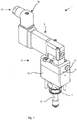
- Figure 1 shows a dispensing module 1.
- the dispensing module 1 has an actuator 3 which in the present example is in the form of a solenoid valve.
- the actuator 3 is connected to a module housing 5 of the dispensing module 1.
- the dispensing module 1 also has an adapter 7 connected to the module housing 5.
- a nozzle holder 9 is connected to the adapter 7 of the dispensing module 1.
- the module housing 5 is of a two-part structure.
- the two-part module housing has a cylinder housing 13 and a housing cover 15.
- a sound damper 17 is provided in the housing cover 15. It is screwed into the housing cover 15 of the module housing.
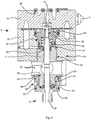
- Figure 2 shows a side view of the dispensing module 1 of Figure 1 .
- a part of the dispensing module 1 in Figure 2 is shown as a sectional view.
- the Figure shows that arranged between the actuator 3 and the housing cover 15 is an insulating plate 21, by means of which the actuator is connected to the module housing 5 or optionally the housing cover 15.
- a sealing element 35 which is in the form of a sealing plate and which extends around a multiplicity of bores.
- respective individual sealing elements could be provided here, but for reasons of manufacture and assembly it is deemed to be preferable to provide an individual sealing element which seals off those multiplicity of bores.
- a first conduit 23 for a control fluid, for example air and a second conduit 25 for a control fluid, for example air.
- the dispensing module 1 is adapted to move a valve piston 33.
- the valve piston is accommodated within the module housing, in particular in a cylindrical portion of the cylinder housing 13. See in that respect also Figure 3 .
- the valve control of such valves is generally known so that for the sake of clarity there will not be a detailed description here relating to control of the fluid in the conduits 23, 25 by means of the actuator 3.
- the adapter 7 has a plurality of recesses 27 which mutually cross and each extend completely through the adapter 7. In that way a valve stem 29 of the valve body is visible from the exterior. In addition the recesses 27 are to be used for assembly purposes.
- the adapter 7 is screwed to the module housing 5, in particular to the cylinder housing 13 of the module housing 5, see in that respect Figure 3 .
- the nozzle holder 9 is also screwed to the adapter 7.
- the valve stem 29 of the valve body extends through the adapter 7 and the nozzle holder 9. At its proximal end the valve body has a valve head 31.
- the enlarged view in Figure 3 showing a first region of the sectional view of the portion shown in Figure 2 of the dispensing module 1 substantially shows the distal part of the valve arrangement.
- the valve piston 33 is movable without play in a cylindrical portion 37 within the cylinder housing 13.
- a return means 39 preferably in the form of a spring holds the valve body in a normally closed position (NC).
- NC normally closed position
- the valve stem 29 has a threaded portion forming a screw connection 38 to a corresponding threaded portion in the valve piston 33.
- the valve stem 29 is fixedly connected to the valve piston 33 by means of a lock nut 41 and the screw connection 38.
- the thread of the screw connection 38 has a reduced pitch.
- the adapter 7 At a distal end 41 of the adapter 7 the latter is connected to the module housing 5, in particular the cylinder housing 13, by means of a screw connection 43. At the distal end 41 the adapter 7 has a positioning element 45 in the form of a centering shoulder. In the assembled condition shown in Figure 3 the positioning element 45 co-operates with a positioning element 47, in the form of a centering bore, of the module housing 5, in particular the cylinder housing 13. In that way the adapter 7 is connected to the module housing 5 free of play and in a definitely positioned relationship.
- the adapter 7 further has a proximal end 49 at which the adapter 7 and the nozzle holder 9 are connected by means of a screw connection 51.
- the adapter also has a positioning element 53 in the form of a centering shoulder and co-operating with a corresponding positioning element 55 in the form of a centering bore in the nozzle holder 9.
- the nozzle holder has a plurality of blind holes 63.
- the blind holes 63 are adapted for accommodating corresponding engagement elements of an assembly and disassembly tool, for example an assembly wrench.
- the nozzle holder 9 has a first O-ring 57 and a second O-ring 59 arranged along the periphery of the nozzle holder.
- the nozzle holder 9 has an axial sealing element 61 which is in contact with a corresponding surface of the adapter 7 and the nozzle holder 9.
- the nozzle holder may comprise a flange-like end portion, at the surface of which the axial sealing element is correspondingly arranged. It will be noted however that a corresponding surface of the adapter 7 is provided for that purpose in the embodiment of Figure 3 .
- a seal receiving means 65 which permits a simplified arrangement of a radial sealing element. It is pushed into the region of the seal receiving means 65 and positioned and supported by assembly of the nozzle holder 9.
- Figure 4 shows a further region of the dispensing module 1 shown in cross section in Figure 2 .
- Figure 4 shows in particular details relating to the nozzle holder 9 of the dispensing module 1.
- the nozzle holder 9 comprises one or more feed openings 67 for the fluid to be dispensed.
- a cavity 69 for transport of the fluid fed through the feed opening 67.
- the cavity comprises a first portion 71.
- an enlarged cross-section is provided in the portion 71.
- the valve stem 29 is narrowed in the region 71.
- the cavity comprises a portion 73 of reduced cross-section.
- the nozzle holder 9 comprises an elongate region 75.
- a narrow gap 77 is formed in that elongate region 75.
- the cross-section is not reduced in the portion 73, but the diameter of the valve stem 79 is increased so that this alternative also affords an elongate region with a narrow gap.
- both the cross-section in the portion 73 is reduced and also the diameter of the valve stem 79 is increased.
- valve seat 79 which in the operative position shown in Figure 4 is in fluid-tight contact with a contact surface 81 of the valve head 31. In that condition this is referred to as the closed position.
- the valve head 31 substantially comprises a mushroom-type shape.
- Figure 5 in contrast to Figure 4 , shows the valve in an open position.
- the valve head 31 has been moved from the closed position into the open position by a stroke X together with the valve stem 29 and the valve piston 33 (not shown).
- Figure 5 once again emphasises the elongate region 75, the length of which is a multiple of the width of the narrow gap 77.
- the contact surface 81 of the valve head 31 is of a substantially conical configuration, the cone comprising an aperture angle ⁇ . In Figure 5 the aperture angle ⁇ is about 120°.
- An opening of an internal width O has been cleared by movement of the valve head 31 by the stroke X into the open position. In the example shown in Figure 5 , the internal width O is less than a width S of the gap 77.
- the internal width O is half as great as the width of the gap S. Further preferably the internal width O is 0.6 times the gap S and particularly preferably the internal width O is greater than the width of the gap S. In the Figure 5 embodiment the length of the elongate region 75 is approximately 15 times as great as the width S of the narrow gap 77.
Landscapes
- Coating Apparatus (AREA)
- Nozzles (AREA)
- Adhesives Or Adhesive Processes (AREA)
Description
- The present invention concerns a dispensing module for an applicator head for dispensing a fluid, in particular hot-melt adhesive.
- The invention further concerns a nozzle holder for such a dispensing module and an applicator head having such a module.
- The above-mentioned units are used in all areas of industry when fluids, in particular adhesives, have to be applied to substrates by means of applicator heads. For that purpose, the applicator heads usually have especially shaped nozzles. These can be nozzles which are of a slit-shaped or slot-shaped nozzle geometry, individual (spray) nozzles or a plurality of intermittently arranged nozzle openings. Depending on the respective area of use, application by means of the applicator heads is effected in contact with the substrate or in contact-free relationship. In the course of the past years the need for systems affording high operational efficiency has progressively increased. In that way the development of ever more powerful systems has been driven onward, which on the one hand are intended to ensure application as precise as possible, and which on the other hand are intended to operate at high speed and with the lowest possible consumption of adhesive. In that respect, a particular requirement involves the intermittent application of adhesive. The latter is effected for example by
means of valves which can be rapidly switched, for example by using solenoid valves. - Systems of the general kind set forth are available for example under the product line Speed-Coat™ of the present applicant Nordson Corporation.
- While the known systems already provide entirely satisfactory working results and are operated with a high level of reliability, there is however a need for improvement in regard to adjustability of the valves used in the modules. When using rapidly operable modules, valves with an elongate valve body are usually employed, which move away from their valve seat into an open position by a given stroke travel and then return to a closed position again. The precise length of the stroke is very difficult to adjust in practice and certain adjustment tolerances have to be accepted. The tolerance in terms of fluid dispensing behaves in a similar manner to the setting of that stroke tolerance. In other words, the occurrence of fluctuations in the fluid discharge has to be accepted.
- Taking that as the basic starting point, the object of the present invention is to provide a dispensing module, a nozzle holder and an applicator head, which achieve an increase in application quality even at a high cycle rate for the valve used.
- The invention attains its object in a dispensing module of the kind set forth in the opening part of this specification, with the features of
claim 1. - A dispensing module according to the preamble is known from
DE 100 10 952 A1 . - The dispensing module according to the invention for an applicator head for dispensing a fluid, in particular hot-melt adhesive, comprising a module housing, a valve body accommodated in the module housing, an adapter through which the valve body extends, comprising a proximal end and a distal end, the distal end being connected by means of a screw connection to the module housing, a nozzle holder which is adapted to be inserted into a matching recess in a base member of the applicator head, and one or a plurality of sealing elements for sealing the nozzle holder and the base member against each other in a fluid-tight manner, wherein the nozzle holder comprises a cavity through which the valve body extends, is connected by means of a screw connection to the proximal end of the adapter, comprises a valve
seat which is adapted to cooperate with a valve head of the valve body, and comprises an elongate section upstream from the valve seat, within which the cavity is limited to a narrow gap. - The invention makes use of the realisation that the flow characteristics within the nozzle holder upstream of the valve and directly at the valve have a decisive influence on the fluid flow passing between the valve seat and the valve head. The amount of fluid passing between the valve seat and the valve head crucially depends on the pressure drop produced by opening of the valve. In the case of the known dispensing systems, because of the adjustment tolerances of the valve stroke, tolerances occurred in terms of the opening diameter of the valve, which similarly led to fluctuations in pressure drop caused by the varying opening diameter between the valve seat and the valve head and thus also fluctuations in the fluid discharge. Because in accordance with the invention, however, upstream of the valve seat there is provided an elongate section within which the cavity is limited to a narrow gap, the crucial pressure drop is now no longer created directly in the opening between the valve seat and the valve head, but already occurs when flowing through the narrow gap. The longer and narrower the gap is, the greater is the corresponding pressure drop which has occurred until reaching the opening cross-section between the valve seat and the valve head. The consequence of this is that fluctuations in pressure drop, having been possibly caused in addition by an inconstant or excessively short stroke of the valve head from the valve seat are scarcely crucial or are not crucial at all. Thus, the fluid discharge is decisively determined by the length and narrowness of the gap but not by the exact setting of the stroke movement of the valve. Thus, extremely precise adjustment of the valve stroke becomes substantially redundant and/or the number of switching cycles, after the attainment of which re-adjustment of the valve becomes necessary, is drastically reduced. The size of the gap defining the pressure drop in the elongate section can be produced and predicted with a high level of precision and involving less time involvement than would be possible by way of (fine) adjustment of the stroke while fitting the valve piston in the module.
- According to the invention the elongate section is of a length which is a multiple of the width of the narrow gap. The length of the elongate gap preferably is in a range of 14 to 20 times the width of the gap. Particularly preferred, the length of the elongate gap is 15 times the width of the gap.
- The width of the narrow gap is preferably in a range of 0.3 mm to 0.7 mm. Particularly preferred the width of the narrow gap is 0.5 mm.
- The combination of the aforementioned preferred ranges of values for the length and width of the gap in the elongate region represents an unexpectedly good compromise for a large number of fluids, in particular for a large number of hot-melt adhesives. Because of the greatly differing fluid characteristics even under similar pressure and/or temperature conditions, a particularly advantageous configuration is one with which a plurality of fluids can be satisfactorily conveyed, without a respective separate implementation of the valve geometry having to be provided.
- In an advantageous development the elongate section is arranged adjacent the valve seat. Although it also alternatively appears to be possible for the elongate section to be arranged further upstream than directly adjoining the valve seat, the positional combination of the narrow gap and the valve seat is deemed to be advantageous to minimise additional fluidic effects which could otherwise occur between the elongate region with the narrow gap and the valve seat.
- In a preferred embodiment the valve piston is movable between a closed position in which the valve head is in fluid-tight contact with the valve seat and an open position, and the closed position and the open position are spaced from each other by a stroke X. Preferably the opening cleared by means of the stroke X is larger than that of the narrow gap. The larger the opening cleared by the stroke X in relation to the cleared cross-section in comparison with the narrow gap, the correspondingly less is the influence of the precise size of the stroke on the pressure drop produced. The size of the
stroke X upwardly is in principle unlimited and is at most limited by the required cycle frequency of the module or valve. Preferably the magnitude of the stroke X is 0.3 mm or less. That ensures operation with a high cycle frequency and at the same time there is a sufficiently large opening between the valve seat and the valve head so that the influence on the pressure drop remains low. - The valve seat preferably has a seat surface with an aperture angle α in a range of 120° to 140°, preferably 124°. The larger the aperture angle α, which is equivalent to a progressively flatter conical configuration for the end face of the valve seat, the correspondingly greater is the increase in the cleared opening when the stroke movement is performed between the closed position and the open position. In that respect the internal width between the surface of the valve seat and the corresponding surface of the valve head is decisive.
- Preferably, alternatively or additionally, the valve head has a surface matching the seat surface of the valve seat, with an aperture angle between 120 and 140, preferably 120°.
- In a further preferred embodiment the adapter comprises a positioning element, preferably a centering shoulder, at its distal end, and the module housing comprises a corresponding positioning element, preferably a centering bore. The term 'distal' in the context of this application is used to mean the side or orientation of the adapter facing away from the valve opening in the condition of being fitted ready for operation. As a counterpart the term 'proximal' is used to mean the side of the adapter facing towards the valve opening in the operationally correct fitted position.
- Preferably at the proximal end the adapter comprises a positioning element, preferably a centering shoulder, and the nozzle holder comprises a corresponding positioning element, preferably a centering bore.
- In a further advantageous development of the dispensing module, two O-rings are arranged as sealing elements along the periphery of the nozzle holder, and an axial and/or cone-shaped sealing element is disposed at a flange portion of the nozzle holder, the O-ring being configured to seal
against a matching cylindrical surface of the recess accommodating the nozzle holder and the axial and/or conical sealing element for sealing against a matching surface or edge of the recess accommodating the nozzle holder. The above-described combination of various sealing elements combines an altogether excellent sealing property with a simple and inexpensive structure and fitment capability, and this provides that the external environment of the nozzle holder which in the mounted condition is the recess accommodating same in the applicator head can be reliably and permanently kept free from fluid. - In a further advantageous embodiment of the invention, the valve body is fixed to a valve piston by means of a screw connection. Preferably the piston comprises a threaded portion produced by means of thread forming, and/or the threaded bore corresponding to the threaded portion of the valve piston is produced by means of thread forming. That achieves an increase in the thread strength which affords a longer service life or longer maintenance intervals for the dispensing module. The threaded portion of the valve body and the corresponding threaded bore preferably have a reduced thread pitch. That permits adjustment of the valve body more precisely, even if only limitedly necessary according to the invention. What is still relevant is adjustment of the position of the valve piston to make the minimum stroke sufficiently large. When that is achieved, as described above, the influence of the stroke on the pressure drop which is decisive in terms of fluid discharge is minimised.
- The object of the invention is further attained in relation to a nozzle holder of the kind set forth in the opening part of this specification, which is adapted to be inserted into a corresponding recess of a base member of the applicator head and which comprises a cavity through which the valve body extends, is connected by means of a screw connection to the proximal end of the adapter, comprises a valve seat adapted to co-operate with a valve head of the valve body, and comprises an elongate section upstream of the valve seat, within which the cavity is limited to a narrow gap.
- Advantageous embodiments of the nozzle holder will be apparent from the foregoing description relating to the preferred embodiments of the dispensing module according to the invention (to which reference is made in the full entirety thereof).
- In addition the object of the invention is attained in relation to an applicator head of the kind set forth in the opening part of this specification, which comprises a base member having a recess, one or a plurality of flow channels connected in fluid communication with the recess, one or a plurality of dispensing orifices connected in fluid communication to the one or the plurality of flow channels, and a dispensing module according to one or more of the preferred embodiments of the present invention, comprising a nozzle holder according to the present invention, which is inserted into the recess in such a way that the one or plurality of dispensing orifices are connected in fluid communication to the cavity of the nozzle holder when the valve is in an open position. Advantages and further configurations of the applicator head according to the invention will also be apparent from the embodiments described hereinbefore of the nozzle holder according to the invention and the dispensing module according to the invention, in which respect attention is directed to that description in its full entirety.
- The invention is described in greater detail hereinafter by means of preferred embodiments and with reference to the accompanying Figures in which:
-
Figure 1 shows a perspective view of the dispensing module according to the invention in a preferred embodiment, -
Figure 2 shows a partly sectional side view of the dispensing module ofFigure 1 , -
Figure 3 shows a view on an enlarged scale of a part of the structure shown inFigure 2 , -
Figure 4 shows a further detail view of the structure ofFigure 2 , and -
Figure 5 shows a detail view on an enlarged scale of the structure inFigures 2 and4 . -
Figure 1 shows adispensing module 1. Thedispensing module 1 has anactuator 3 which in the present example is in the form of a solenoid valve. Theactuator 3 is connected to amodule housing 5 of thedispensing module 1. Thedispensing module 1 also has anadapter 7 connected to themodule housing 5. Anozzle holder 9 is connected to theadapter 7 of thedispensing module 1. - Provided on the
actuator 3 is aconnector socket 19 having anelectrical connection 11 for the feed of electric energy for controlling theactuator 3. In the present embodiment themodule housing 5 is of a two-part structure. In this embodiment the two-part module housing has acylinder housing 13 and ahousing cover 15. Asound damper 17 is provided in thehousing cover 15. It is screwed into thehousing cover 15 of the module housing. -
Figure 2 shows a side view of thedispensing module 1 ofFigure 1 . In regard to repeated references attention is directed to the description relating toFigure 1 . That also applies to the other Figures and references which are repeated therein. A part of thedispensing module 1 inFigure 2 is shown as a sectional view. In particular the Figure shows that arranged between theactuator 3 and thehousing cover 15 is an insulatingplate 21, by means of which the actuator is connected to themodule housing 5 or optionally thehousing cover 15. Provided between the insulatingplate 21 and themodule housing 5 is a sealingelement 35 which is in the form of a sealing plate and which extends around a multiplicity of bores. Alternatively, respective individual sealing elements could be provided here, but for reasons of manufacture and assembly it is deemed to be preferable to provide an individual sealing element which seals off those multiplicity of bores. Provided within thecylinder housing 13 are afirst conduit 23 for a control fluid, for example air, and asecond conduit 25 for a control fluid, for example air. By means of thoseconduits dispensing module 1 is adapted to move avalve piston 33. The valve piston is accommodated within the module housing, in particular in a cylindrical portion of thecylinder housing 13. See in that respect alsoFigure 3 . The valve control of such
valves is generally known so that for the sake of clarity there will not be a detailed description here relating to control of the fluid in theconduits actuator 3. - The
adapter 7 has a plurality ofrecesses 27 which mutually cross and each extend completely through theadapter 7. In that way avalve stem 29 of the valve body is visible from the exterior. In addition therecesses 27 are to be used for assembly purposes. Theadapter 7 is screwed to themodule housing 5, in particular to thecylinder housing 13 of themodule housing 5, see in that respectFigure 3 . - The
nozzle holder 9 is also screwed to theadapter 7. The valve stem 29 of the valve body extends through theadapter 7 and thenozzle holder 9. At its proximal end the valve body has avalve head 31. - The enlarged view in
Figure 3 showing a first region of the sectional view of the portion shown inFigure 2 of thedispensing module 1 substantially shows the distal part of the valve arrangement. Thevalve piston 33 is movable without play in acylindrical portion 37 within thecylinder housing 13. A return means 39 preferably in the form of a spring holds the valve body in a normally closed position (NC). In that position of thevalve piston 33 the valve head 31 (seeFigure 2 andFigure 4 ) is in a closed position relative to the valve seat (seeFigure 4 ). The valve stem 29 has a threaded portion forming ascrew connection 38 to a corresponding threaded portion in thevalve piston 33. The valve stem 29 is fixedly connected to thevalve piston 33 by means of alock nut 41 and thescrew connection 38. Optionally the thread of thescrew connection 38 has a reduced pitch. - At a
distal end 41 of theadapter 7 the latter is connected to themodule housing 5, in particular thecylinder housing 13, by means of ascrew connection 43. At thedistal end 41 theadapter 7 has apositioning element 45 in the form of a centering shoulder. In the assembled condition shown inFigure 3 thepositioning element 45 co-operates with apositioning element 47, in the form of a centering bore, of themodule housing 5, in particular thecylinder housing 13. In that way theadapter 7 is connected to themodule housing 5 free of play and in a definitely positioned relationship. - The
adapter 7 further has aproximal end 49 at which theadapter 7 and thenozzle holder 9 are connected by means of ascrew connection 51. In the region of theproximal end 49, the adapter also has apositioning element 53 in the form of a centering shoulder and co-operating with acorresponding positioning element 55 in the form of a centering bore in thenozzle holder 9. At its peripheral surface the nozzle holder has a plurality ofblind holes 63. Theblind holes 63 are adapted for accommodating corresponding engagement elements of an assembly and disassembly tool, for example an assembly wrench. - As sealing means, the
nozzle holder 9 has a first O-ring 57 and a second O-ring 59 arranged along the periphery of the nozzle holder. In addition, in a preferred embodiment thenozzle holder 9 has anaxial sealing element 61 which is in contact with a corresponding surface of theadapter 7 and thenozzle holder 9. Alternatively the nozzle holder may comprise a flange-like end portion, at the surface of which the axial sealing element is correspondingly arranged. It will be noted however that a corresponding surface of theadapter 7 is provided for that purpose in the embodiment ofFigure 3 . In addition, in the embodiment ofFigure 3 there is a seal receiving means 65 which permits a simplified arrangement of a radial sealing element. It is pushed into the region of the seal receiving means 65 and positioned and supported by assembly of thenozzle holder 9. - As regards
Figures 3 ,4 and5 , reference is made to the foregoing description with respect to repeated reference signs.Figure 4 shows a further region of thedispensing module 1 shown in cross section inFigure 2 .Figure 4 shows in particular details relating to thenozzle holder 9 of thedispensing module 1. Thenozzle holder 9 comprises one ormore feed openings 67 for the fluid to be dispensed. Provided within thenozzle holder 9 is acavity 69 for transport of the fluid fed through thefeed opening 67. The cavity comprises afirst portion 71. In a preferred embodiment an enlarged cross-section is provided in theportion 71. In addition in a further preferred embodiment thevalve stem 29 is narrowed in theregion 71. Furthermore the cavity comprises aportion 73 of reduced cross-section. Because of the reduction in cross-section in theportion 73 thenozzle holder 9 comprises anelongate region 75. Anarrow gap 77 is formed in thatelongate region 75. In a preferred alternative the cross-section is not reduced in theportion 73, but the diameter of thevalve stem 79 is increased so that this alternative also affords an elongate region with a narrow gap. In a further preferred alternative both the cross-section in theportion 73 is reduced and also the diameter of thevalve stem 79 is increased. - Provided at the proximal end of the
nozzle holder 9 is avalve seat 79 which in the operative position shown inFigure 4 is in fluid-tight contact with acontact surface 81 of thevalve head 31. In that condition this is referred to as the closed position. Thevalve head 31 substantially comprises a mushroom-type shape. -
Figure 5 , in contrast toFigure 4 , shows the valve in an open position. Thevalve head 31 has been moved from the closed position into the open position by a stroke X together with thevalve stem 29 and the valve piston 33 (not shown).Figure 5 once again emphasises theelongate region 75, the length of which is a multiple of the width of thenarrow gap 77. Thecontact surface 81 of thevalve head 31 is of a substantially conical configuration, the cone comprising an aperture angle α. InFigure 5 the aperture angle α is about 120°. An opening of an internal width O has been cleared by movement of thevalve head 31 by the stroke X into the open position. In the example shown inFigure 5 , the internal width O is less than a width S of thegap 77. Preferably, the internal width O is half as great as the width of the gap S. Further preferably the internal width O is 0.6 times the gap S and particularly preferably the internal width O is greater than the width of the gap S. In theFigure 5 embodiment the length of theelongate region 75 is approximately 15 times as great as the width S of thenarrow gap 77.
Claims (10)
- A dispensing module (1) for use with an applicator head having a base member with a recess for dispensing a fluid, in particular hot-melt adhesive, comprising- a module housing (5),- a valve body in the module housing (5) and having a valve stem (29) and a valve head (31),- an adapter (7) through which the valve body extends, comprising a proximal end (49) and a distal end (41), the distal end (41) being connected by means of a screw connection (43) to the module housing (5),- a nozzle holder (9) having a cavity (69) through which the valve body extends and being adapted to be inserted into the matching recess in the base member of the applicator head, and- one or a plurality of sealing elements (57, 59, 61) for sealing the nozzle holder (9) and the base member against each other in a fluid-tight manner,characterized in that the nozzle holder (9)- is connected by means of a screw connection (51) to the proximal end (49) of the adapter (7);- comprises a valve seat (79) which is adapted to cooperate with the valve head (31) of the valve body, wherein the amount of fluid passing between the valve seat and the valve head depends on the pressure drop produced by opening of the valve; andcomprises an elongate section (75) upstream from the valve seat (79), a narrow gap (77) being formed in the elongate section (75), the gap having a width (S) between the valve stem (29) and the nozzle holder (9) and a length that is a multiple of the width (S) of the narrow gap such that said pressure drop already occurs when said fluid is flowing through said narrow gap (77).
- The dispensing module (1) according to claim 1,
in which the length of the elongate section is in a range of 14 to 20 times the width S of the narrow gap (77). - The dispensing module (1) according to claim 2,
wherein the width (S) of the narrow gap (77) is in a range between 0.3 mm and 0.5 mm. - The dispensing module (1) according to any of the preceding claims,
wherein the elongate section (75) is adjacent the valve seat (79). - The dispensing module (1) according to any of the preceding claims,
wherein the valve body is movable between a closed position in which the valve head (31) is in fluid-tight contact with the valve seat (79), and an open position, the closed position and the open position being spaced apart from each other by a stroke (X), and the orifice which is released by means of stroke (X) being larger than that of the narrow gap (77). - The dispensing module (1) according to any of the preceding claims,
wherein the valve seat (79), comprises a seat surface having an aperture angle in the range between 120° and 140°, preferably 124°. - The dispensing module (1) according to claim 6,
wherein the valve head (31) comprises a surface (81) matching the surface of the valve seat and having an aperture angle between 115° and 140°, preferably 120°. - The dispensing module (1) according to any of the preceding claims,
wherein the adapter (7) comprises a positioning element (45), preferably a centering shoulder, at its distal end (41) and the module housing (5) comprises a matching positioning element (47), preferably a centering bore. - The dispensing module (1) according to claim 8,
wherein the adapter (7) comprises a positioning element (53), preferably a centering shoulder, at its proximal end (49) and the nozzle holder (9) comprises a matching positioning element (55), preferably a centering bore. - A dispensing head for dispensing a fluid, in particular hot-melt adhesive, comprising- a base member comprising a recess,- one or a plurality of flow channels connected in fluid communication with the recess,- one or a plurality of dispensing orifices connected in fluid communication to the one or the plurality of flow channels, and- a dispensing module (1) according to any of claims 1 to 9, comprising a nozzle holder (9), said nozzle holder being inserted into the recess in such a way that the one or plurality of dispensing orifices are connected in fluid communication to the cavity of the nozzle holder (9) when the valve is in an open position.
Applications Claiming Priority (2)
| Application Number | Priority Date | Filing Date | Title |
|---|---|---|---|
| DE202011107265U DE202011107265U1 (en) | 2011-10-31 | 2011-10-31 | Dispensing module, applicator head and nozzle for dispensing a fluid, in particular hot melt adhesive |
| PCT/IB2012/002149 WO2013064876A1 (en) | 2011-10-31 | 2012-10-17 | Dispensing module, applicator head and nozzle holder for dispensing a fluid, in particular hot-melt adhesive |
Publications (2)
| Publication Number | Publication Date |
|---|---|
| EP2773462A1 EP2773462A1 (en) | 2014-09-10 |
| EP2773462B1 true EP2773462B1 (en) | 2019-04-03 |
Family
ID=47178769
Family Applications (1)
| Application Number | Title | Priority Date | Filing Date |
|---|---|---|---|
| EP12787078.0A Active EP2773462B1 (en) | 2011-10-31 | 2012-10-17 | Dispensing module, applicator head and nozzle holder for dispensing a fluid, in particular hot-melt adhesive |
Country Status (7)
| Country | Link |
|---|---|
| US (1) | US9682394B2 (en) |
| EP (1) | EP2773462B1 (en) |
| JP (1) | JP6122025B2 (en) |
| CN (1) | CN103917300B (en) |
| DE (1) | DE202011107265U1 (en) |
| ES (1) | ES2730174T3 (en) |
| WO (1) | WO2013064876A1 (en) |
Families Citing this family (14)
| Publication number | Priority date | Publication date | Assignee | Title |
|---|---|---|---|---|
| CN107073507B (en) * | 2014-10-27 | 2019-07-05 | 格瑞克明尼苏达有限公司 | Quick release solenoid component |
| US9925552B2 (en) * | 2015-03-09 | 2018-03-27 | Nordson Corporation | Liquid dispensing applicators having backpressure control devices, and related methods |
| EP3231518B1 (en) * | 2016-04-15 | 2023-10-11 | Jowat SE | Bar-shaped hot melt adhesive for hot glue gun |
| EP3509759B1 (en) | 2016-09-08 | 2020-11-04 | Nordson Corporation | Applicator with diverter plate |
| WO2018205682A1 (en) * | 2017-05-08 | 2018-11-15 | 常州铭赛机器人科技股份有限公司 | Fluid micro-injection device and flow channel assembly |
| CN111182977B (en) * | 2017-10-03 | 2022-07-19 | 堺显示器制品株式会社 | Nozzle connector, nozzle connector set, coating device, and coating system |
| CN107716212A (en) * | 2017-11-30 | 2018-02-23 | 苏州特瑞特机器人有限公司 | Double-liquid refrigeration dispenser |
| CN113117989B (en) * | 2021-04-16 | 2025-07-11 | 微密斯点胶技术有限公司 | A dosing system |
| USD1079896S1 (en) * | 2021-04-30 | 2025-06-17 | Nordson Corporation | Applicator module |
| USD1027134S1 (en) | 2021-04-30 | 2024-05-14 | Nordson Corporation | Connector for a material dispensing assembly |
| USD1066448S1 (en) | 2021-04-30 | 2025-03-11 | Nordson Corporation | Applicator assembly |
| USD1085187S1 (en) * | 2021-05-12 | 2025-07-22 | Innovative Automation Inc. | Applicator head for taping machine |
| JP7775707B2 (en) * | 2021-12-28 | 2025-11-26 | 株式会社リコー | Droplet ejection module, droplet ejection head, and droplet ejection device |
| CN117225649A (en) * | 2023-09-22 | 2023-12-15 | 东莞市凯格精机股份有限公司 | A dispensing valve and dispensing equipment |
Citations (2)
| Publication number | Priority date | Publication date | Assignee | Title |
|---|---|---|---|---|
| WO2005009627A2 (en) * | 2003-07-14 | 2005-02-03 | Nordson Corporation | Apparatus and method for dispensing discrete amounts of viscous material |
| KR101006640B1 (en) * | 2010-10-14 | 2011-01-10 | 이구환 | Nozzle Unit for Dispensing |
Family Cites Families (20)
| Publication number | Priority date | Publication date | Assignee | Title |
|---|---|---|---|---|
| US4759477A (en) | 1985-06-17 | 1988-07-26 | Corporation Loctite | Variable flow rate dispensing valve assembly |
| EP0286212A3 (en) * | 1987-04-09 | 1989-08-30 | Acumeter Laboratories Inc. | Fluid nozzle applicator |
| US4907741A (en) * | 1987-04-09 | 1990-03-13 | Acumeter Laboratories, Inc. | Poppet-valve-controlled fluid nozzle applicator |
| US5010841A (en) * | 1989-05-23 | 1991-04-30 | Mcdonnell Douglas Corporation | Rotating sealant applicator |
| DE4211942C2 (en) * | 1992-04-09 | 1995-09-07 | Wallner Harald | Glue application valve |
| DE29622341U1 (en) * | 1996-12-23 | 1997-04-03 | Nordson Corp., Westlake, Ohio | Device for applying flowable material to a substrate, in particular for the intermittent application of liquid adhesive |
| US5875922A (en) * | 1997-10-10 | 1999-03-02 | Nordson Corporation | Apparatus for dispensing an adhesive |
| DE10010952A1 (en) * | 2000-03-06 | 2001-09-27 | Nordson Corp Westlake | Device for intermittent application of free-flowing material has main and additional actuating units for movement of valve component relative to valve seat and each with pneumatically operated piston movable in cylinder |
| US6334554B1 (en) * | 2000-04-17 | 2002-01-01 | Illinois Tool Works Inc. | Snuffback valve for hot melt adhesive |
| JP2002361122A (en) | 2001-06-12 | 2002-12-17 | Asahi Sunac Corp | Air spray gun |
| DE20112891U1 (en) * | 2001-08-03 | 2001-10-18 | Nordson Corporation, Westlake, Ohio | Device for dispensing flowable material onto a substrate that is movable relative to the device |
| US6669057B2 (en) * | 2001-10-31 | 2003-12-30 | Nordson Corporation | High-speed liquid dispensing modules |
| FR2832079B1 (en) * | 2001-11-14 | 2004-07-30 | Valois Sa | DISPENSING HEAD AND FLUID PRODUCT DISPENSER COMPRISING SUCH A DISPENSING HEAD |
| FR2838070B1 (en) * | 2002-04-04 | 2005-02-11 | Valois Sa | DISTRIBUTION HEAD TO BE MOUNTED ON A MOBILE HOLLOW ACTUATING ROD |
| US7771556B2 (en) * | 2005-07-01 | 2010-08-10 | Nordson Corporation | Apparatus and process to apply adhesive during labeling operations |
| FR2917651B1 (en) * | 2007-06-20 | 2010-09-17 | Rexam Dispensing Sys | PUMP FOR DISTRIBUTION OF AN IMPROVED LIQUID IMPROVED PRODUCT |
| JP5830799B2 (en) * | 2008-09-18 | 2015-12-09 | ノードソン コーポレーションNordson Corporation | Automated vacuum assisted valve pretreatment system and method of use |
| DE102009038924B3 (en) * | 2009-08-26 | 2011-02-24 | Drei Bond Gmbh | Method for filling fluid over component surface, involves leading fluid to regulating valve through conductor, where regulating valve is led to outlet opening |
| FR2951442B1 (en) * | 2009-10-20 | 2012-01-20 | Valois Sas | DISPENSING HEAD FOR FLUID PRODUCT DISPENSING DEVICE. |
| DE102010006067A1 (en) * | 2010-01-28 | 2010-09-16 | Daimler Ag | Application tool for applying viscous media, has application nozzle, which is held with media channel for conveying media for application nozzle |
-
2011
- 2011-10-31 DE DE202011107265U patent/DE202011107265U1/en not_active Expired - Lifetime
-
2012
- 2012-10-17 ES ES12787078T patent/ES2730174T3/en active Active
- 2012-10-17 CN CN201280053658.8A patent/CN103917300B/en active Active
- 2012-10-17 EP EP12787078.0A patent/EP2773462B1/en active Active
- 2012-10-17 US US14/354,368 patent/US9682394B2/en active Active
- 2012-10-17 JP JP2014539416A patent/JP6122025B2/en active Active
- 2012-10-17 WO PCT/IB2012/002149 patent/WO2013064876A1/en not_active Ceased
Patent Citations (2)
| Publication number | Priority date | Publication date | Assignee | Title |
|---|---|---|---|---|
| WO2005009627A2 (en) * | 2003-07-14 | 2005-02-03 | Nordson Corporation | Apparatus and method for dispensing discrete amounts of viscous material |
| KR101006640B1 (en) * | 2010-10-14 | 2011-01-10 | 이구환 | Nozzle Unit for Dispensing |
Also Published As
| Publication number | Publication date |
|---|---|
| CN103917300B (en) | 2018-02-06 |
| US9682394B2 (en) | 2017-06-20 |
| JP6122025B2 (en) | 2017-04-26 |
| JP2015502838A (en) | 2015-01-29 |
| ES2730174T3 (en) | 2019-11-08 |
| EP2773462A1 (en) | 2014-09-10 |
| CN103917300A (en) | 2014-07-09 |
| US20140299680A1 (en) | 2014-10-09 |
| WO2013064876A1 (en) | 2013-05-10 |
| DE202011107265U1 (en) | 2013-02-11 |
Similar Documents
| Publication | Publication Date | Title |
|---|---|---|
| US9682394B2 (en) | Dispensing module, applicator head and nozzle holder for dispensing a fluid, in particular hot-melt adhesive | |
| EP2001600B1 (en) | Shower head | |
| US7837071B2 (en) | Valve device of an application device for applying fluid to a substrate, and applicator | |
| US10150134B2 (en) | Liquid dispensing applicators having backpressure control devices, and related methods | |
| EP3027943B1 (en) | Improvements in hydraulic servovalves | |
| KR20140005292A (en) | Multi-spray bidet | |
| US20160016200A1 (en) | Pneumatic product sorting apparatus | |
| KR20200093473A (en) | Proportional flow control valve poppet with flow control needle | |
| US20180250702A1 (en) | Liquid dispensing module | |
| CA2641508C (en) | Spray coating system and method | |
| US12083544B2 (en) | Nozzle | |
| US20100206917A1 (en) | Tip and stem valve assembly | |
| CN110167680B (en) | Dual-material nozzle, showerhead, and method | |
| US10711811B2 (en) | Pneumatic servovalve assembly | |
| US20120292405A1 (en) | Apparatus and method for jetting liquid material in desired patterns | |
| HK1122528B (en) | Shower head |
Legal Events
| Date | Code | Title | Description |
|---|---|---|---|
| PUAI | Public reference made under article 153(3) epc to a published international application that has entered the european phase |
Free format text: ORIGINAL CODE: 0009012 |
|
| 17P | Request for examination filed |
Effective date: 20140602 |
|
| AK | Designated contracting states |
Kind code of ref document: A1 Designated state(s): AL AT BE BG CH CY CZ DE DK EE ES FI FR GB GR HR HU IE IS IT LI LT LU LV MC MK MT NL NO PL PT RO RS SE SI SK SM TR |
|
| RIN1 | Information on inventor provided before grant (corrected) |
Inventor name: MARX, WOLFGANG Inventor name: MUELLER, MANFRED |
|
| DAX | Request for extension of the european patent (deleted) | ||
| 17Q | First examination report despatched |
Effective date: 20151215 |
|
| GRAP | Despatch of communication of intention to grant a patent |
Free format text: ORIGINAL CODE: EPIDOSNIGR1 |
|
| STAA | Information on the status of an ep patent application or granted ep patent |
Free format text: STATUS: GRANT OF PATENT IS INTENDED |
|
| INTG | Intention to grant announced |
Effective date: 20181012 |
|
| GRAS | Grant fee paid |
Free format text: ORIGINAL CODE: EPIDOSNIGR3 |
|
| GRAA | (expected) grant |
Free format text: ORIGINAL CODE: 0009210 |
|
| STAA | Information on the status of an ep patent application or granted ep patent |
Free format text: STATUS: THE PATENT HAS BEEN GRANTED |
|
| AK | Designated contracting states |
Kind code of ref document: B1 Designated state(s): AL AT BE BG CH CY CZ DE DK EE ES FI FR GB GR HR HU IE IS IT LI LT LU LV MC MK MT NL NO PL PT RO RS SE SI SK SM TR |
|
| REG | Reference to a national code |
Ref country code: GB Ref legal event code: FG4D |
|
| REG | Reference to a national code |
Ref country code: CH Ref legal event code: EP Ref country code: AT Ref legal event code: REF Ref document number: 1115070 Country of ref document: AT Kind code of ref document: T Effective date: 20190415 |
|
| REG | Reference to a national code |
Ref country code: DE Ref legal event code: R096 Ref document number: 602012058617 Country of ref document: DE |
|
| REG | Reference to a national code |
Ref country code: IE Ref legal event code: FG4D |
|
| REG | Reference to a national code |
Ref country code: NL Ref legal event code: MP Effective date: 20190403 |
|
| REG | Reference to a national code |
Ref country code: LT Ref legal event code: MG4D |
|
| REG | Reference to a national code |
Ref country code: AT Ref legal event code: MK05 Ref document number: 1115070 Country of ref document: AT Kind code of ref document: T Effective date: 20190403 |
|
| PG25 | Lapsed in a contracting state [announced via postgrant information from national office to epo] |
Ref country code: NL Free format text: LAPSE BECAUSE OF FAILURE TO SUBMIT A TRANSLATION OF THE DESCRIPTION OR TO PAY THE FEE WITHIN THE PRESCRIBED TIME-LIMIT Effective date: 20190403 |
|
| PG25 | Lapsed in a contracting state [announced via postgrant information from national office to epo] |
Ref country code: SE Free format text: LAPSE BECAUSE OF FAILURE TO SUBMIT A TRANSLATION OF THE DESCRIPTION OR TO PAY THE FEE WITHIN THE PRESCRIBED TIME-LIMIT Effective date: 20190403 Ref country code: FI Free format text: LAPSE BECAUSE OF FAILURE TO SUBMIT A TRANSLATION OF THE DESCRIPTION OR TO PAY THE FEE WITHIN THE PRESCRIBED TIME-LIMIT Effective date: 20190403 Ref country code: NO Free format text: LAPSE BECAUSE OF FAILURE TO SUBMIT A TRANSLATION OF THE DESCRIPTION OR TO PAY THE FEE WITHIN THE PRESCRIBED TIME-LIMIT Effective date: 20190703 Ref country code: AL Free format text: LAPSE BECAUSE OF FAILURE TO SUBMIT A TRANSLATION OF THE DESCRIPTION OR TO PAY THE FEE WITHIN THE PRESCRIBED TIME-LIMIT Effective date: 20190403 Ref country code: PT Free format text: LAPSE BECAUSE OF FAILURE TO SUBMIT A TRANSLATION OF THE DESCRIPTION OR TO PAY THE FEE WITHIN THE PRESCRIBED TIME-LIMIT Effective date: 20190803 Ref country code: LT Free format text: LAPSE BECAUSE OF FAILURE TO SUBMIT A TRANSLATION OF THE DESCRIPTION OR TO PAY THE FEE WITHIN THE PRESCRIBED TIME-LIMIT Effective date: 20190403 Ref country code: HR Free format text: LAPSE BECAUSE OF FAILURE TO SUBMIT A TRANSLATION OF THE DESCRIPTION OR TO PAY THE FEE WITHIN THE PRESCRIBED TIME-LIMIT Effective date: 20190403 Ref country code: CZ Free format text: LAPSE BECAUSE OF FAILURE TO SUBMIT A TRANSLATION OF THE DESCRIPTION OR TO PAY THE FEE WITHIN THE PRESCRIBED TIME-LIMIT Effective date: 20190403 |
|
| REG | Reference to a national code |
Ref country code: ES Ref legal event code: FG2A Ref document number: 2730174 Country of ref document: ES Kind code of ref document: T3 Effective date: 20191108 |
|
| PG25 | Lapsed in a contracting state [announced via postgrant information from national office to epo] |
Ref country code: LV Free format text: LAPSE BECAUSE OF FAILURE TO SUBMIT A TRANSLATION OF THE DESCRIPTION OR TO PAY THE FEE WITHIN THE PRESCRIBED TIME-LIMIT Effective date: 20190403 Ref country code: RS Free format text: LAPSE BECAUSE OF FAILURE TO SUBMIT A TRANSLATION OF THE DESCRIPTION OR TO PAY THE FEE WITHIN THE PRESCRIBED TIME-LIMIT Effective date: 20190403 Ref country code: BG Free format text: LAPSE BECAUSE OF FAILURE TO SUBMIT A TRANSLATION OF THE DESCRIPTION OR TO PAY THE FEE WITHIN THE PRESCRIBED TIME-LIMIT Effective date: 20190703 Ref country code: GR Free format text: LAPSE BECAUSE OF FAILURE TO SUBMIT A TRANSLATION OF THE DESCRIPTION OR TO PAY THE FEE WITHIN THE PRESCRIBED TIME-LIMIT Effective date: 20190704 Ref country code: PL Free format text: LAPSE BECAUSE OF FAILURE TO SUBMIT A TRANSLATION OF THE DESCRIPTION OR TO PAY THE FEE WITHIN THE PRESCRIBED TIME-LIMIT Effective date: 20190403 |
|
| PG25 | Lapsed in a contracting state [announced via postgrant information from national office to epo] |
Ref country code: IS Free format text: LAPSE BECAUSE OF FAILURE TO SUBMIT A TRANSLATION OF THE DESCRIPTION OR TO PAY THE FEE WITHIN THE PRESCRIBED TIME-LIMIT Effective date: 20190803 Ref country code: AT Free format text: LAPSE BECAUSE OF FAILURE TO SUBMIT A TRANSLATION OF THE DESCRIPTION OR TO PAY THE FEE WITHIN THE PRESCRIBED TIME-LIMIT Effective date: 20190403 |
|
| REG | Reference to a national code |
Ref country code: DE Ref legal event code: R097 Ref document number: 602012058617 Country of ref document: DE |
|
| PG25 | Lapsed in a contracting state [announced via postgrant information from national office to epo] |
Ref country code: DK Free format text: LAPSE BECAUSE OF FAILURE TO SUBMIT A TRANSLATION OF THE DESCRIPTION OR TO PAY THE FEE WITHIN THE PRESCRIBED TIME-LIMIT Effective date: 20190403 Ref country code: EE Free format text: LAPSE BECAUSE OF FAILURE TO SUBMIT A TRANSLATION OF THE DESCRIPTION OR TO PAY THE FEE WITHIN THE PRESCRIBED TIME-LIMIT Effective date: 20190403 Ref country code: SK Free format text: LAPSE BECAUSE OF FAILURE TO SUBMIT A TRANSLATION OF THE DESCRIPTION OR TO PAY THE FEE WITHIN THE PRESCRIBED TIME-LIMIT Effective date: 20190403 Ref country code: RO Free format text: LAPSE BECAUSE OF FAILURE TO SUBMIT A TRANSLATION OF THE DESCRIPTION OR TO PAY THE FEE WITHIN THE PRESCRIBED TIME-LIMIT Effective date: 20190403 |
|
| PLBE | No opposition filed within time limit |
Free format text: ORIGINAL CODE: 0009261 |
|
| STAA | Information on the status of an ep patent application or granted ep patent |
Free format text: STATUS: NO OPPOSITION FILED WITHIN TIME LIMIT |
|
| PG25 | Lapsed in a contracting state [announced via postgrant information from national office to epo] |
Ref country code: SM Free format text: LAPSE BECAUSE OF FAILURE TO SUBMIT A TRANSLATION OF THE DESCRIPTION OR TO PAY THE FEE WITHIN THE PRESCRIBED TIME-LIMIT Effective date: 20190403 |
|
| 26N | No opposition filed |
Effective date: 20200106 |
|
| PG25 | Lapsed in a contracting state [announced via postgrant information from national office to epo] |
Ref country code: TR Free format text: LAPSE BECAUSE OF FAILURE TO SUBMIT A TRANSLATION OF THE DESCRIPTION OR TO PAY THE FEE WITHIN THE PRESCRIBED TIME-LIMIT Effective date: 20190403 |
|
| PG25 | Lapsed in a contracting state [announced via postgrant information from national office to epo] |
Ref country code: MC Free format text: LAPSE BECAUSE OF FAILURE TO SUBMIT A TRANSLATION OF THE DESCRIPTION OR TO PAY THE FEE WITHIN THE PRESCRIBED TIME-LIMIT Effective date: 20190403 Ref country code: SI Free format text: LAPSE BECAUSE OF FAILURE TO SUBMIT A TRANSLATION OF THE DESCRIPTION OR TO PAY THE FEE WITHIN THE PRESCRIBED TIME-LIMIT Effective date: 20190403 |
|
| REG | Reference to a national code |
Ref country code: CH Ref legal event code: PL |
|
| PG25 | Lapsed in a contracting state [announced via postgrant information from national office to epo] |
Ref country code: CH Free format text: LAPSE BECAUSE OF NON-PAYMENT OF DUE FEES Effective date: 20191031 Ref country code: LU Free format text: LAPSE BECAUSE OF NON-PAYMENT OF DUE FEES Effective date: 20191017 Ref country code: LI Free format text: LAPSE BECAUSE OF NON-PAYMENT OF DUE FEES Effective date: 20191031 |
|
| REG | Reference to a national code |
Ref country code: BE Ref legal event code: MM Effective date: 20191031 |
|
| PG25 | Lapsed in a contracting state [announced via postgrant information from national office to epo] |
Ref country code: BE Free format text: LAPSE BECAUSE OF NON-PAYMENT OF DUE FEES Effective date: 20191031 |
|
| GBPC | Gb: european patent ceased through non-payment of renewal fee |
Effective date: 20191017 |
|
| PG25 | Lapsed in a contracting state [announced via postgrant information from national office to epo] |
Ref country code: FR Free format text: LAPSE BECAUSE OF NON-PAYMENT OF DUE FEES Effective date: 20191031 Ref country code: GB Free format text: LAPSE BECAUSE OF NON-PAYMENT OF DUE FEES Effective date: 20191017 Ref country code: IE Free format text: LAPSE BECAUSE OF NON-PAYMENT OF DUE FEES Effective date: 20191017 |
|
| PG25 | Lapsed in a contracting state [announced via postgrant information from national office to epo] |
Ref country code: CY Free format text: LAPSE BECAUSE OF FAILURE TO SUBMIT A TRANSLATION OF THE DESCRIPTION OR TO PAY THE FEE WITHIN THE PRESCRIBED TIME-LIMIT Effective date: 20190403 |
|
| PG25 | Lapsed in a contracting state [announced via postgrant information from national office to epo] |
Ref country code: HU Free format text: LAPSE BECAUSE OF FAILURE TO SUBMIT A TRANSLATION OF THE DESCRIPTION OR TO PAY THE FEE WITHIN THE PRESCRIBED TIME-LIMIT; INVALID AB INITIO Effective date: 20121017 Ref country code: MT Free format text: LAPSE BECAUSE OF FAILURE TO SUBMIT A TRANSLATION OF THE DESCRIPTION OR TO PAY THE FEE WITHIN THE PRESCRIBED TIME-LIMIT Effective date: 20190403 |
|
| PG25 | Lapsed in a contracting state [announced via postgrant information from national office to epo] |
Ref country code: MK Free format text: LAPSE BECAUSE OF FAILURE TO SUBMIT A TRANSLATION OF THE DESCRIPTION OR TO PAY THE FEE WITHIN THE PRESCRIBED TIME-LIMIT Effective date: 20190403 |
|
| P01 | Opt-out of the competence of the unified patent court (upc) registered |
Effective date: 20230527 |
|
| REG | Reference to a national code |
Ref country code: DE Ref legal event code: R082 Ref document number: 602012058617 Country of ref document: DE Representative=s name: TER MEER STEINMEISTER & PARTNER PATENTANWAELTE, DE |
|
| PGFP | Annual fee paid to national office [announced via postgrant information from national office to epo] |
Ref country code: DE Payment date: 20251021 Year of fee payment: 14 |
|
| PGFP | Annual fee paid to national office [announced via postgrant information from national office to epo] |
Ref country code: IT Payment date: 20251024 Year of fee payment: 14 |
|
| PGFP | Annual fee paid to national office [announced via postgrant information from national office to epo] |
Ref country code: ES Payment date: 20251210 Year of fee payment: 14 |