EP2773441B1 - Air filter assembly - Google Patents
Air filter assembly Download PDFInfo
- Publication number
- EP2773441B1 EP2773441B1 EP12780382.3A EP12780382A EP2773441B1 EP 2773441 B1 EP2773441 B1 EP 2773441B1 EP 12780382 A EP12780382 A EP 12780382A EP 2773441 B1 EP2773441 B1 EP 2773441B1
- Authority
- EP
- European Patent Office
- Prior art keywords
- inset collar
- sealing structure
- collar
- inset
- sub
- Prior art date
- Legal status (The legal status is an assumption and is not a legal conclusion. Google has not performed a legal analysis and makes no representation as to the accuracy of the status listed.)
- Active
Links
- 238000007789 sealing Methods 0.000 claims description 25
- 239000000463 material Substances 0.000 description 13
- 239000000356 contaminant Substances 0.000 description 5
- 238000002485 combustion reaction Methods 0.000 description 4
- 238000004519 manufacturing process Methods 0.000 description 4
- 239000006185 dispersion Substances 0.000 description 3
- 239000000428 dust Substances 0.000 description 3
- 239000007789 gas Substances 0.000 description 3
- 239000004033 plastic Substances 0.000 description 3
- 229920003023 plastic Polymers 0.000 description 3
- JOYRKODLDBILNP-UHFFFAOYSA-N Ethyl urethane Chemical compound CCOC(N)=O JOYRKODLDBILNP-UHFFFAOYSA-N 0.000 description 2
- 230000009286 beneficial effect Effects 0.000 description 2
- 230000015572 biosynthetic process Effects 0.000 description 2
- 229920002678 cellulose Polymers 0.000 description 2
- 239000001913 cellulose Substances 0.000 description 2
- 238000001914 filtration Methods 0.000 description 2
- 238000009434 installation Methods 0.000 description 2
- 238000000034 method Methods 0.000 description 2
- 238000010137 moulding (plastic) Methods 0.000 description 2
- 239000000654 additive Substances 0.000 description 1
- 230000002411 adverse Effects 0.000 description 1
- 230000000712 assembly Effects 0.000 description 1
- 238000000429 assembly Methods 0.000 description 1
- QVGXLLKOCUKJST-UHFFFAOYSA-N atomic oxygen Chemical compound [O] QVGXLLKOCUKJST-UHFFFAOYSA-N 0.000 description 1
- 238000004891 communication Methods 0.000 description 1
- 230000000052 comparative effect Effects 0.000 description 1
- 238000007599 discharging Methods 0.000 description 1
- 230000000694 effects Effects 0.000 description 1
- 229920001971 elastomer Polymers 0.000 description 1
- 239000012530 fluid Substances 0.000 description 1
- 239000010410 layer Substances 0.000 description 1
- 238000005259 measurement Methods 0.000 description 1
- 239000002184 metal Substances 0.000 description 1
- 239000000203 mixture Substances 0.000 description 1
- 238000000465 moulding Methods 0.000 description 1
- 239000001301 oxygen Substances 0.000 description 1
- 229910052760 oxygen Inorganic materials 0.000 description 1
- 229920002635 polyurethane Polymers 0.000 description 1
- 239000004814 polyurethane Substances 0.000 description 1
- 238000010248 power generation Methods 0.000 description 1
- 239000002356 single layer Substances 0.000 description 1
- 238000011144 upstream manufacturing Methods 0.000 description 1
Images






Classifications
-
- B—PERFORMING OPERATIONS; TRANSPORTING
- B01—PHYSICAL OR CHEMICAL PROCESSES OR APPARATUS IN GENERAL
- B01D—SEPARATION
- B01D46/00—Filters or filtering processes specially modified for separating dispersed particles from gases or vapours
- B01D46/24—Particle separators, e.g. dust precipitators, using rigid hollow filter bodies
-
- B—PERFORMING OPERATIONS; TRANSPORTING
- B01—PHYSICAL OR CHEMICAL PROCESSES OR APPARATUS IN GENERAL
- B01D—SEPARATION
- B01D46/00—Filters or filtering processes specially modified for separating dispersed particles from gases or vapours
- B01D46/0039—Filters or filtering processes specially modified for separating dispersed particles from gases or vapours with flow guiding by feed or discharge devices
- B01D46/0047—Filters or filtering processes specially modified for separating dispersed particles from gases or vapours with flow guiding by feed or discharge devices for discharging the filtered gas
- B01D46/0049—Filters or filtering processes specially modified for separating dispersed particles from gases or vapours with flow guiding by feed or discharge devices for discharging the filtered gas containing fixed gas displacement elements or cores
-
- B—PERFORMING OPERATIONS; TRANSPORTING
- B01—PHYSICAL OR CHEMICAL PROCESSES OR APPARATUS IN GENERAL
- B01D—SEPARATION
- B01D46/00—Filters or filtering processes specially modified for separating dispersed particles from gases or vapours
- B01D46/24—Particle separators, e.g. dust precipitators, using rigid hollow filter bodies
- B01D46/2403—Particle separators, e.g. dust precipitators, using rigid hollow filter bodies characterised by the physical shape or structure of the filtering element
- B01D46/2411—Filter cartridges
-
- B—PERFORMING OPERATIONS; TRANSPORTING
- B01—PHYSICAL OR CHEMICAL PROCESSES OR APPARATUS IN GENERAL
- B01D—SEPARATION
- B01D46/00—Filters or filtering processes specially modified for separating dispersed particles from gases or vapours
- B01D46/24—Particle separators, e.g. dust precipitators, using rigid hollow filter bodies
- B01D46/2403—Particle separators, e.g. dust precipitators, using rigid hollow filter bodies characterised by the physical shape or structure of the filtering element
- B01D46/2411—Filter cartridges
- B01D46/2414—End caps including additional functions or special forms
-
- B—PERFORMING OPERATIONS; TRANSPORTING
- B01—PHYSICAL OR CHEMICAL PROCESSES OR APPARATUS IN GENERAL
- B01D—SEPARATION
- B01D46/00—Filters or filtering processes specially modified for separating dispersed particles from gases or vapours
- B01D46/42—Auxiliary equipment or operation thereof
- B01D46/4272—Special valve constructions adapted to filters or filter elements
-
- B—PERFORMING OPERATIONS; TRANSPORTING
- B01—PHYSICAL OR CHEMICAL PROCESSES OR APPARATUS IN GENERAL
- B01D—SEPARATION
- B01D46/00—Filters or filtering processes specially modified for separating dispersed particles from gases or vapours
- B01D46/42—Auxiliary equipment or operation thereof
- B01D46/44—Auxiliary equipment or operation thereof controlling filtration
-
- B—PERFORMING OPERATIONS; TRANSPORTING
- B01—PHYSICAL OR CHEMICAL PROCESSES OR APPARATUS IN GENERAL
- B01D—SEPARATION
- B01D46/00—Filters or filtering processes specially modified for separating dispersed particles from gases or vapours
- B01D46/56—Filters or filtering processes specially modified for separating dispersed particles from gases or vapours with multiple filtering elements, characterised by their mutual disposition
- B01D46/62—Filters or filtering processes specially modified for separating dispersed particles from gases or vapours with multiple filtering elements, characterised by their mutual disposition connected in series
-
- B—PERFORMING OPERATIONS; TRANSPORTING
- B01—PHYSICAL OR CHEMICAL PROCESSES OR APPARATUS IN GENERAL
- B01D—SEPARATION
- B01D46/00—Filters or filtering processes specially modified for separating dispersed particles from gases or vapours
- B01D46/56—Filters or filtering processes specially modified for separating dispersed particles from gases or vapours with multiple filtering elements, characterised by their mutual disposition
- B01D46/62—Filters or filtering processes specially modified for separating dispersed particles from gases or vapours with multiple filtering elements, characterised by their mutual disposition connected in series
- B01D46/64—Filters or filtering processes specially modified for separating dispersed particles from gases or vapours with multiple filtering elements, characterised by their mutual disposition connected in series arranged concentrically or coaxially
-
- B—PERFORMING OPERATIONS; TRANSPORTING
- B01—PHYSICAL OR CHEMICAL PROCESSES OR APPARATUS IN GENERAL
- B01D—SEPARATION
- B01D2258/00—Sources of waste gases
- B01D2258/06—Polluted air
-
- B—PERFORMING OPERATIONS; TRANSPORTING
- B01—PHYSICAL OR CHEMICAL PROCESSES OR APPARATUS IN GENERAL
- B01D—SEPARATION
- B01D2271/00—Sealings for filters specially adapted for separating dispersed particles from gases or vapours
- B01D2271/02—Gaskets, sealings
- B01D2271/027—Radial sealings
Definitions
- This disclosure relates to air filter assemblies suitable for use in engine air intake systems.
- Air streams can carry contaminant material therein.
- air flow streams to engines for example combustion air
- gas streams to gas turbine systems and air streams to various combustion furnaces carry particulate contaminant therein that should be filtered.
- selected contaminant material be removed from (or have its level reduced in) the air.
- a variety of air filter arrangements have been developed for contaminant rejection. In many instances, especially where government regulations require, it is also desired to measure the mass flow rate of the filtered air that will be delivered. In some applications, it is desirable to include an air metering device within the air filter arrangement.
- An air filter assembly having a primary filter element, a secondary filter element, and a housing with an outlet tube is disclosed as background art.
- the housing has an interior volume defined by a sidewall extending between a first end and a second end.
- the housing also has an air inlet opening in the sidewall and an air outlet opening in the first end.
- the primary filter element is operably installed within the housing and has an interior volume defined by a first wall extending between a closed end cap and an opposite open end cap.
- the secondary filter element is operably installed within the primary filter element interior volume and has an interior volume defined by a first wall extending between a closed end cap and an opposite open end cap.
- the open end cap of the secondary filter element defines a sealing structure having a first portion extending into the secondary filter interior volume.
- the outlet tube is operably connected to the housing air outlet opening and includes an inset collar being at least partially disposed within the secondary filter interior volume and extending over at least a part of the sealing structure first portion.
- a secondary filter element according to the present invention is claimed in independent claim 1.
- FIGS. 1-9 are provided as background art.
- air filter assembly 100 is shown as further including an optional dust ejection valve 120.
- Dust ejection valve 120 is for discharging accumulated debris within the housing 102 via a cyclone effect occurring inside the housing.
- dust ejection valve 120 is a duckbill valve.
- a duckbill valve One skilled in the art will appreciate that other types of valves known in the art may also be used.
- air filter assembly 100 also includes an optional metering devices 162a, 162b.
- Metering devices 162a, 162b can be for measuring an aspect of the clean airflow stream 20.
- One example of an aspect of the clean airflow stream 20 is the velocity of the air.
- the metering devices 162a, 162b may also measure air pressure.
- Another example is the oxygen content of the airflow stream 20.
- Yet another example of an aspect of the clean airflow stream 20 is the temperature.
- metering device 162b is a hot wire anemometer configured to output a pulse width modulation signal proportional to the mass air flow rate of the airflow stream 20.
- Other types of metering devices are suitable for this type of measurement, such as vane meter sensors and vortex shedding sensors.
- vane meter sensors and vortex shedding sensors One skilled in the art will appreciate that other types of metering devices known in the art may also be used.
- air filter assembly 100 includes a primary filter element 200 which can be best seen in FIGS. 2 and 3 .
- Primary filter element 200 is exposed to the dirty airflow stream 10 and filters the air to create clean airflow stream 20.
- primary filter element includes a first wall of filter media 202 formed into the shape of a tube that extends between an open end cap 204 and an opposite closed end cap 206.
- the end caps 204, 206 are molded from a resilient urethane material.
- the resulting media and end cap structure defines an interior volume 210.
- the dirty airflow stream 10 is exposed to the exterior of the first wall of filter media 202 which passes through the first wall of filter media 202 into the interior volume 210.
- the primary filter can be provided with or without an outer liner, and can be provided with or without an inner liner.
- the primary filter element 200 will comprise pleated media and no inner liner and no outer liner.
- the media will typically be pleated and may include corrugations extending generally perpendicularly to the pleat tips, to facilitate keeping the pleats open during use.
- Various pleat tip folding techniques can be used to facilitate this, as are common in the art. Examples of this can be found in media packs having the mark "Pleatloc" from Donaldson Company, Inc., of Minneapolis, MN, the Assignee of the present disclosure.
- the open end cap 204 defines a sealing structure 208 that encases an end of the first wall of filter media 202.
- Sealing structure 208 is for providing a radial seal between the exterior of the primary filter element 200 and the interior volume 210 such that the dirty airflow stream 10 cannot bypass the filter media 202 and mix with clean airflow stream 20.
- sealing structure 208 forms a radial seal with the outlet tube 150.
- Sealing structure 208 may be made from a variety of materials, such as polyurethane and rubber.
- secondary filter element 250 includes a first wall of media 252 formed into the shape of a tube that extends between an open end cap 254 and an opposite closed end cap 256.
- the end caps 254, 266 are molded from a resilient urethane material.
- This structure defines an interior volume 260 which is in uninterrupted and direct fluid communication with the outlet tube 150 of the air filter assembly.
- the interior volume has an internal diameter D.sub.3.
- the first wall of media 252 can be made from synthetic or natural materials and can be pleated or non-pleated.
- media 252 can include pleated cellulose, pleated or flat cellulose/synthetic and spun bond materials treated with special additives.
- Media wall 252 can also have a single layer or multiple layers of media.
- the secondary filter element 250 can also be formed with an inner and/or an outer liner for increased structural strength.
- media wall 252 comprises two layers of filter media and a liner.
- the open end cap 254 of secondary filter 250 defines a sealing structure 258 that encases an end of the first wall of filter media 252.
- Sealing structure 258 is for providing a seal between the exterior of the secondary filter element 250 and the interior volume 260 such that air cannot bypass the filter media 252 into outlet tube 150.
- Sealing structure 258 includes a first portion 258a that extends into interior volume 260 along an interior side 252a of the first wall of filter media 252. In the embodiment shown, first portion 258 has a length L.sub.4 that is about 25 mm.
- Sealing structure 258 also includes a second portion 258b and a third portion 258c that extend over the end portion and an exterior side 252b of the first wall of filter media 252, respectively. Third portion 258c is configured to form a radial seal against the outlet tube 150.
- air filter assembly 100 includes a housing 102, as can be seen most easily in FIGS. 1-3 .
- housing 102 has a sidewall 104 extending between a first end 106 and a second end 108 that together define an internal volume 118. It is within internal volume 118 that the primary filter element 200 and the secondary filter element 250 are installed, their closed ends being nearest the second end 108 of the housing 102.
- the housing 102 is constructed to have a first shell 102a and a separable second shell 102b that allow for access into the interior volume 118.
- the first and second shells are held together by fastening means 110.
- the fastening means 110 is a plurality of clasps 110.
- the filter assembly housing 102 is also provided with mounting band 112 for mounting the filter assembly 100 to a structure, such as a motorized vehicle.
- the outlet tube 150 has a first section 150a configured for connection to the housing first end 106 and a second section 150b configured for connection to an outlet hose (not shown).
- the first and second sections 150a, 150b are at about right angles to each other and form an elbow.
- the first and second sections 150a, 150b can be at other angles to each other, including being in line with each other to form a straight outlet tube 150.
- the first section 150a and the housing 102 share a common longitudinal axis 122, as illustrated in FIG. 1 .
- the first section of outlet tube 150 is also shown as including an inset collar 156.
- Inset collar 156 is for minimizing the airflow flow dispersion and maximizing the flow stability of the clean airflow stream 20 flowing from the secondary filter element internal volume 260 as it is introduced into outlet tube 150.
- a typical end cap on the secondary filter element can cause significant disruption to the airflow which in turn adversely affects the readings one might obtain from a metering device 162b.
- the inset collar 156 extends at least partially into the interior volume 260 of the secondary filter element 250. As shown most clearly in FIG. 6 , inset collar 156 extends into the interior volume 260 of the secondary filter element and over the first portion 258a of the sealing structure 258. Such a configuration allows for air flowing within interior volume 260 to be directed into the first section 150a of the outlet tube 150 without passing over the first portion 258a of the sealing structure 258 of the open end cap 250.
- One benefit of this arrangement is that irregularities in the dimensions of the sealing structure 258 can be shielded from air flow and thus prevented from disrupting the air flow.
- length L.sub.2 is substantially greater than length L.sub.4. In other embodiments, length L.sub.2 allows inset collar 156 to at least partially cover the seal structure first portion 258a of the secondary element 250. In other embodiments, length L.sub.2 is long enough for inset collar 156 to at cover a majority of the seal structure first portion 258a along length L.sub.4. In still other embodiments, length L.sub.2 is equal to or greater than the length L.sub.4 of the seal structure first portion 258a such that the first portion 258a is fully covered. In certain embodiments, length L.sub.2 is at least one quarter of the inner diameter D.sub.3 of the secondary filter element 250. In other embodiments, length L.sub.2 is at least one third the inner diameter D.sub.3 of the secondary filter element 250.
- the first section of outlet tube 150 also includes a sensor port 160a, 160b to accommodate the installation of the airflow metering device 162a, 162b or other sensing device.
- port 160b is a distance L.sub.3 above the end 156a of the inset collar 156.
- the first portion 150a of the outlet tube 150 has a smooth surface which allows for the clean airflow 20 to have an enhanced velocity profile leading up to metering device 162.
- This configuration also results in a ratio of L.sub.3 to D.sub.1. of about 2.3 to 1 to 2.5 to 1. It is desirable for this ratio to be at least 1 to 1, and more preferable for this ratio to be at least 2 to 1.
- the ratio of L.sub.3 to the actual diameter of the inlet tube at the sensor port 160b is also desirable for the ratio of L.sub.3 to the actual diameter of the inlet tube at the sensor port 160b (slightly less than D.sub.1 due to the draft angle) to be at least 1.1 to 1.
- length L.sub.2 provides at least 20% of the total length L.sub.3 from the upstream end of the inset collar 156 to the flow metering device.
- the second section 150b of outlet tube 150 is shown as being at about a right angle to the first section 150a. Because of this configuration, the location of where the metering device 162b can be mounted is constrained and limits length L.sub.3 to a location where the airflow is still traveling in a uniform direction before the elbow.
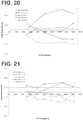
- FIG. 21 represents test results for the same filter elements, but with the inset collar 156 installed, and shows that the flow dispersion percentage range is reduced to a range from about +0.2% to about -0.2%.
- FIG. 22 shows similar comparative results for improvements in flow stability percentage with the inset collar 156 present.
- inset collar 156' is provided at a shorter length L.sub.2' and does not extend the full length of the first portion 258a of the secondary filter element seal structure 258. Also, inset collar 156' is attached to the seal structure 258 of the secondary filter element 250. An additional inset collar 220 having a length L.sub.5 is provided attached to the first seal structure portion 258a. Insert collar 220 is configured to mate with the end of the inset collar 156' at an interface location 222 to form an assembled inset collar.
- the inset collars 156' and 220 can be configured to have teeth, splines or other positive registration means to ensure that they have mated together properly at interface location 222.
- the inset collar 220' is attached directly to the secondary filter element 250 in FIG. 8 .
- the inset collar 156' is attached to an interior liner 250a of filter element 250.
- the interior liner 250a of filter element 250 and inset collar 220' can be formed from the same or different materials and can be plastic, metal, or other types of materials. In a preferred embodiment, interior liner 250a and inset collar 220' are both plastic.
- inset collar 1220 has a length L.sub.5 of about 32.5 millimeters (mm) and an average internal diameter D.sub.4 of about 66 mm. Due to manufacturing limitations for some materials, especially with plastic molding requiring at least some draft angle, it is sometimes not possible to obtain a perfectly parallel internal wall. As such, the sidewall of the inset collar 1220 may form a generally constant diameter, but have a slight taper.
- the length L.sub.5 of the inset collar 1220 is greater than the length L.sub.4 of the seal structure 258 by about 8 mm.
- the greater length of L.sub.5 is beneficial in accommodating manufacturing variances in the length L.sub.4 of the seal structure, nominally shown as being 24 mm, thereby ensuring that the seal structure first portion 258a is entirely covered by the inset collar 1220.
- the inset collar 1220 is arranged with respect to the seal structure 258 such that the inset collar 1220 extends past the seal structure first surface 258a in an axial direction towards the closed end cap of the filter, resulting in the formation of an interior volume 260.
- the inset collar 1220 is provided with a plurality of protrusions extending radially outward from the inset collar 1220.
- the protrusions are in the form of radially spaced tabs 1221 and ribs 1223.
- the radially spaced tabs 1221 are configured to engage with the seal structure 258 such that the seal structure 258 may be molded and secured onto the inset collar 1220.
- Figure 13 shows one of the tabs 1221 embedded in the seal structure 258.
- the radially spaced ribs 1223 are provided to ensure proper alignment and spacing between the filter media 252 and the inset collar 1220.
- each rib 1223 has a first portion 1223a that is tapered to allow the filter media 252 to more easily be inserted over the inset collar 1220 and a second portion 1223b that extends to the underside of the tab 1221. As shown, the ribs 1223 extend a distance of about 4 mm from the interior surface 1220a of the inset collar 1220 while the tabs extends about 8.5 mm from the interior surface 1220a.
- inset collar 1220' is similar to that shown in FIGS 10-14 , but is configured to be removable from the seal structure 258.
- inset collar 1220' can be pressed into and against the first seal structure portion 258a.
- inset collar 1220' has a length of L.sub.5 and an internal diameter D.sub.4.
- inset collar 1220' has a length L.sub.5 of about 33 millimeters (mm) and an average internal diameter D.sub.4 of about 66 mm.
- the inset collar 1220' is provided with a singular flange 1221' and a plurality of radially spaced ribs 1223'. It is noted that a plurality of radially spaced tabs or other such projection(s) can be used instead of the shown flange 1221'.
- the flange 1221' is configured to engage with the top surface 258b of the seal structure 258 such that the inset collar 1220' may be properly received into the seal structure 258.
- the radially spaced ribs 1223' are provided to ensure alignment between the inset collar 1220' and the seal structure 258, and to ensure that the inset collar 1220' is frictionally secured to the seal structure 258.
- each rib 1223' has a first portion 1223a' that is tapered to allow the inset collar 1220' to be more easily inserted into the seal structure 258.
- Each rib 1223' also has a second portion 1223b' that extends to the underside of the flange 1221'. As shown, the ribs extend a distance of about 4.5 mm from the interior surface 1220a' of the inset collar 1220' while the flange extends about 12.5 mm from the interior surface 1220a'.
- sixteen ribs 1223' are provided at an equal spacing about the inset collar 1220'. However, fewer or ribs 1223' may be provided depending upon the application.
Landscapes
- Chemical & Material Sciences (AREA)
- Chemical Kinetics & Catalysis (AREA)
- Physics & Mathematics (AREA)
- Geometry (AREA)
- Filtering Of Dispersed Particles In Gases (AREA)
- Measuring Volume Flow (AREA)
Description
- This disclosure relates to air filter assemblies suitable for use in engine air intake systems.
- Air streams can carry contaminant material therein. In many instances, it is desired to filter some or all of the contaminant material from the air stream. For example, air flow streams to engines (for example combustion air) for motorized vehicles or for power generation equipment, gas streams to gas turbine systems and air streams to various combustion furnaces, carry particulate contaminant therein that should be filtered. It is preferred for such systems, that selected contaminant material be removed from (or have its level reduced in) the air. A variety of air filter arrangements have been developed for contaminant rejection. In many instances, especially where government regulations require, it is also desired to measure the mass flow rate of the filtered air that will be delivered. In some applications, it is desirable to include an air metering device within the air filter arrangement. However, other components within the filter arrangement often cause excessive turbulence thereby minimizing the accuracy of the measured airflow for such a configuration. Improvements are sought. Known filter elements are for example disclosed in
DE 10 2008 008 328 A1 ,WO 99/42719 A2 EP 1 889 648 A2 , and inUS 2010/037570 A1 . - An air filter assembly having a primary filter element, a secondary filter element, and a housing with an outlet tube is disclosed as background art. The housing has an interior
volume defined by a sidewall extending between a first end and a second end. The housing also has an air inlet opening in the sidewall and an air outlet opening in the first end. The primary filter element is operably installed within the housing and has an interior volume defined by a first wall extending between a closed end cap and an opposite open end cap. The secondary filter element is operably installed within the primary filter element interior volume and has an interior volume defined by a first wall extending between a closed end cap and an opposite open end cap. The open end cap of the secondary filter element defines a sealing structure having a first portion extending into the secondary filter interior volume. The outlet tube is operably connected to the housing air outlet opening and includes an inset collar being at least partially disposed within the secondary filter interior volume and extending over at least a part of the sealing structure first portion. - A secondary filter element according to the present invention is claimed in
independent claim 1. -
-
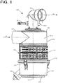
FIG. 1 is a front view of a filter assembly. -
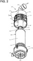
FIG. 2 is a perspective exploded view of the filter assembly shown inFIG. 1 . -
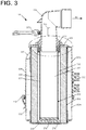
FIG. 3 is a cross-sectional view of the filter assembly shown inFIG. 1 . -
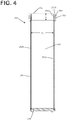
FIG. 4 is a cross-sectional view of a secondary filter suitable for use in the filter assembly shown inFIG. 1 . -
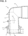
FIG. 5 is a cross-sectional view of an outlet tube suitable for use in the filter assembly shown inFIG. 1 . -
FIG. 6 is an enlarged cross-sectional view of a portion of the filter assembly shown inFIG. 2 . -
FIG. 7 is an enlarged cross-sectional view of a second embodiment of a filter assembly. -
FIG. 8 is an enlarged cross-sectional view of a third embodiment of a filter assembly. -
FIG. 9 is an enlarged cross-sectional view of a fourth embodiment of a filter assembly. -
FIG. 10 is an exploded perspective view of a fifth embodiment of a filter assembly. -
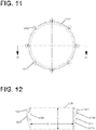
FIG. 11 is a front view of an inset collar usable with the filter assembly shown inFigure 10 . -
FIG. 12 is a cross-sectional view of the inset collar shown inFigure 11 . -
FIG. 13 is a cross-sectional view of a portion of the filter assembly shown inFigure 10 . -
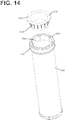
FIG. 14 is an exploded perspective view of a sixth embodiment of a filter assembly. -
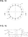
FIG. 15 is a front view of an inset collar usable with the filter assembly shown inFigure 14 . -
FIG. 16 is a cross-sectional view of the inset collar shown inFigure 15 . -
FIG. 17 is a cross-sectional view of a portion of the filter assembly shown inFigure 14 . -
FIG. 18 is a cross-sectional view of the filter assembly shown inFigure 14 installed in a filter housing. -
FIG. 19 is an enlarged cross-sectional view of a portion of the filter assembly shown inFigure 18 . -
FIG. 20 is a schematic chart showing test results for an air filter assembly without the inset collar of the filter assembly shown inFIG. 1 . -
FIG. 21 is a schematic chart showing test results for an air filter assembly with an inset collar. -
FIG. 22 is a schematic comparison chart showing test results for an air filter assembly with and without an inset collar. - Reference will now be made in detail to the exemplary aspects of the present disclosure that are illustrated in the accompanying drawings. Wherever possible, the same reference numbers will be used throughout the drawings to refer to the same or like structure.
FIGS. 1-9 are provided as background art. - With reference to
FIGS. 1-3 , anair filter assembly 100 is shown. For the purposes of the description in this application, air filters are discussed, but the various embodiments described herein also relate to filtration of other gases.Air filter assembly 100 is for filtering adirty air stream 10 to provide aclean airflow stream 20 to an end use device, for example an internal combustion engine. The primary components of theair filter assembly 100 are ahousing 102 having aninlet 114 and anoutlet tube 150, aprimary filter element 200, and asecondary filter element 250. Each of these aspects of the disclosure is discussed in further detail in the following paragraphs. - As can be seen in
FIGS. 1 and2 air filter assembly 100 is shown as further including an optionaldust ejection valve 120.Dust ejection valve 120 is for discharging accumulated debris within thehousing 102 via a cyclone effect occurring inside the housing. In the embodiment shown,dust ejection valve 120 is a duckbill valve. One skilled in the art will appreciate that other types of valves known in the art may also be used. - With reference to
FIGS. 1 and3 ,air filter assembly 100 also includes anoptional metering devices Metering devices clean airflow stream 20. One example of an aspect of theclean airflow stream 20 is the velocity of the air. Themetering devices airflow stream 20. Yet another example of an aspect of theclean airflow stream 20 is the temperature. In the particular embodiment shown,metering device 162b is a hot wire anemometer configured to output a pulse width modulation signal proportional to the mass air flow rate of theairflow stream 20. Other types of metering devices are suitable for this type of measurement, such as vane meter sensors and vortex shedding sensors. One skilled in the art will appreciate that other types of metering devices known in the art may also be used. - As stated above,
air filter assembly 100 includes aprimary filter element 200 which can be best seen inFIGS. 2 and3 .Primary filter element 200 is exposed to thedirty airflow stream 10 and filters the air to createclean airflow stream 20. As shown, primary filter element includes a first wall offilter media 202 formed into the shape of a tube that extends between anopen end cap 204 and an oppositeclosed end cap 206. In the particular embodiment shown, the end caps 204, 206 are molded from a resilient urethane material. The resulting media and end cap structure defines aninterior volume 210. In operation, thedirty airflow stream 10 is exposed to the exterior of the first wall offilter media 202 which passes through the first wall offilter media 202 into theinterior volume 210. - It is noted that the primary filter can be provided with or without an outer liner, and can be provided with or without an inner liner. Typically, the
primary filter element 200 will comprise pleated media and no inner liner and no outer liner. The media will typically be pleated and may include corrugations extending generally perpendicularly to the pleat tips, to facilitate keeping the pleats open during use. Various pleat tip folding techniques can be used to facilitate this, as are common in the art. Examples of this can be found in media packs having the mark "Pleatloc" from Donaldson Company, Inc., of Minneapolis, MN, the Assignee of the present disclosure. - As can be most easily seen at
FIGS. 2 and6 , theopen end cap 204 defines a sealingstructure 208 that encases an end of the first wall offilter media 202.Sealing structure 208 is for providing a radial seal between the exterior of theprimary filter element 200 and theinterior volume 210 such that thedirty airflow stream 10 cannot bypass thefilter media 202 and mix withclean airflow stream 20. In the embodiment shown, sealingstructure 208 forms a radial seal with theoutlet tube 150.Sealing structure 208 may be made from a variety of materials, such as polyurethane and rubber. - Installed within the
interior volume 210 of theprimary filter element 200 is thesecondary filter element 250.Secondary filter element 250 is for providing a safety function in the event of a failure or removal ofprimary filter element 200. In this regard,secondary filter element 250 prevents direct exposure of the intake air path to the internal combustion engine to the environment when theprimary filter element 200 is either damaged or removed. - In the embodiment shown,
secondary filter element 250 includes a first wall ofmedia 252 formed into the shape of a tube that extends between anopen end cap 254 and an oppositeclosed end cap 256. In the particular embodiment shown, the end caps 254, 266 are molded from a resilient urethane material. This structure defines aninterior volume 260 which is in uninterrupted and direct fluid communication with theoutlet tube 150 of the air filter assembly. As shown, the interior volume has an internal diameter D.sub.3. The first wall ofmedia 252 can be made from synthetic or natural materials and can be pleated or non-pleated. For example,media 252 can include pleated cellulose, pleated or flat cellulose/synthetic and spun bond materials treated with special additives.Media wall 252 can also have a single layer or multiple layers of media. Thesecondary filter element 250 can also be formed with an inner and/or an outer liner for increased structural strength. In the exemplary embodiment shown,media wall 252 comprises two layers of filter media and a liner. - As can be most easily seen at
FIG. 4 , theopen end cap 254 ofsecondary filter 250 defines a sealingstructure 258 that encases an end of the first wall offilter media 252.Sealing structure 258 is for providing a seal between the exterior of thesecondary filter element 250 and theinterior volume 260 such that air cannot bypass thefilter media 252 intooutlet tube 150.Sealing structure 258 includes afirst portion 258a that extends intointerior volume 260 along aninterior side 252a of the first wall offilter media 252. In the embodiment shown,first portion 258 has a length L.sub.4 that is about 25 mm.Sealing structure 258 also includes asecond portion 258b and athird portion 258c that extend over the end portion and anexterior side 252b of the first wall offilter media 252, respectively.Third portion 258c is configured to form a radial seal against theoutlet tube 150. - As mentioned previously,
air filter assembly 100 includes ahousing 102, as can be seen most easily inFIGS. 1-3 . As shown,housing 102 has asidewall 104 extending between afirst end 106 and asecond end 108 that together define aninternal volume 118. It is withininternal volume 118 that theprimary filter element 200 and thesecondary filter element 250 are installed, their closed ends being nearest thesecond end 108 of thehousing 102. To facilitate the installation and removal of thefilters housing 102 is constructed to have afirst shell 102a and a separablesecond shell 102b that allow for access into theinterior volume 118. The first and second shells are held together by fastening means 110. In the particular embodiment shown, the fastening means 110 is a plurality ofclasps 110. Thefilter assembly housing 102 is also provided with mountingband 112 for mounting thefilter assembly 100 to a structure, such as a motorized vehicle. - The
housing 102 further includes an air inlet opening 114 within thesidewall 104 for allowing entry of thedirty airflow stream 10.Housing 102 also has anoutlet opening 116 defined by thefirst end 106 to allow theclean air stream 20 to exit theinterior volume 118 of the housing. Thefirst end 106 of the housing also defines ashoulder surface 106a and anoutward projection 106b for supporting and retaining theoutlet tube 150 through which theclean airflow stream 20 is delivered. With reference toFIG. 5 , theoutlet tube 150 includes ashoulder 152 and arecess 152a which correspondingly engageshoulder surface 106a andoutward projection 106b, respectively. This structure allows foroutlet tube 150 to be supported and rotatable with respect tohousing 102. - Still referencing
FIG. 5 , theoutlet tube 150 has afirst section 150a configured for connection to the housingfirst end 106 and asecond section 150b configured for connection to an outlet hose (not shown). As shown, the first andsecond sections second sections straight outlet tube 150. In the embodiment shown, thefirst section 150a and thehousing 102 share a commonlongitudinal axis 122, as illustrated inFIG. 1 . - As shown in the drawings, the
first section 150a ofoutlet tube 150 has a generally constant internal diameter, D.sub.1. As used throughout this disclosure, the term "generally constant diameter" is taken to mean that the sidewall does not vary from the longitudinal axis by more than about 5 degrees. Due to manufacturing limitations for some materials, especially with plastic molding requiring at least some draft angle, it is sometimes not possible to obtain a perfectly parallel internal wall. As such, the sidewall may form a generally constant diameter, but have a slight taper. In the embodiment shown,outlet tube 150 is made from plastic and has a draft angle taper of approximately 1 degree such that thefirst section 150a narrows slightly as it extends in a downstream direction towards thesecond section 150b. - In the embodiment shown, the
first section 150a ofoutlet tube 150 includes anouter collar 154. With reference toFIG. 6 ,outer collar 154 provides a firstradial seal 161 against theseal structure 208 of theprimary filter element 200 and a secondradial seal 163 against the third portion 252c of the sealingstructure 252 of thesecondary filter element 250. As constructed,outer collar 154 operates to ensure that unfiltered air from theair flow inlet 114 cannot bypass the primary andsecondary filter elements outlet tube 150. In the embodiment shown,outer collar 154 has a length L.sub.1 of about 30 millimeters (mm) and an average internal diameter D.sub.1 of about 90 mm. - The first section of
outlet tube 150 is also shown as including aninset collar 156.Inset collar 156 is for minimizing the airflow flow dispersion and maximizing the flow stability of theclean airflow stream 20 flowing from the secondary filter elementinternal volume 260 as it is introduced intooutlet tube 150. In certain configurations, a typical end cap on the secondary filter element can cause significant disruption to the airflow which in turn adversely affects the readings one might obtain from ametering device 162b. - In certain embodiments, the
inset collar 156 extends at least partially into theinterior volume 260 of thesecondary filter element 250. As shown most clearly inFIG. 6 ,inset collar 156 extends into theinterior volume 260 of the secondary filter element and over thefirst portion 258a of the sealingstructure 258. Such a configuration allows for air flowing withininterior volume 260 to be directed into thefirst section 150a of theoutlet tube 150 without passing over thefirst portion 258a of the sealingstructure 258 of theopen end cap 250. One benefit of this arrangement is that irregularities in the dimensions of the sealingstructure 258 can be shielded from air flow and thus prevented from disrupting the air flow. - In the particular embodiment shown, the
inset collar 156 has a length L.sub.2 of about 31 mm and an average internal diameter D.sub.2 of about 65 mm such that the resulting gap G.sub.1 between theinset collar 156 and theouter collar 154 is about 13 mm. In some embodiments, length L.sub.2 is greater than the gap G.sub.1. In other embodiments, length L.sub.2 is at least two times greater than the gap G.sub.1. As shown inFIG. 6 , the gap G.sub.1 allows forinset collar 156 to be separated from thefirst portion 258a such that a seal is not formed betweeninset collar 156 and sealingstructure 258. Theinset collar 156 also extends over thefirst portion 258a of theseal structure 258 by an amount equal to the difference between the length of the inset collar L.sub.2 and the length of the first portion L.sub.4. - In certain embodiments, length L.sub.2 is substantially greater than length L.sub.4. In other embodiments, length L.sub.2 allows
inset collar 156 to at least partially cover the seal structurefirst portion 258a of thesecondary element 250. In other embodiments, length L.sub.2 is long enough forinset collar 156 to at cover a majority of the seal structurefirst portion 258a along length L.sub.4. In still other embodiments, length L.sub.2 is equal to or greater than the length L.sub.4 of the seal structurefirst portion 258a such that thefirst portion 258a is fully covered. In certain embodiments, length L.sub.2 is at least one quarter of the inner diameter D.sub.3 of thesecondary filter element 250. In other embodiments, length L.sub.2 is at least one third the inner diameter D.sub.3 of thesecondary filter element 250. - The first section of
outlet tube 150 also includes asensor port airflow metering device port 160b is a distance L.sub.3 above theend 156a of theinset collar 156. Along this length, thefirst portion 150a of theoutlet tube 150 has a smooth surface which allows for theclean airflow 20 to have an enhanced velocity profile leading up to metering device 162. This configuration also results in a ratio of L.sub.3 to D.sub.1. of about 2.3 to 1 to 2.5 to 1. It is desirable for this ratio to be at least 1 to 1, and more preferable for this ratio to be at least 2 to 1. It is also desirable for the ratio of L.sub.3 to the actual diameter of the inlet tube at thesensor port 160b (slightly less than D.sub.1 due to the draft angle) to be at least 1.1 to 1. In certain embodiments, length L.sub.2 provides at least 20% of the total length L.sub.3 from the upstream end of theinset collar 156 to the flow metering device. As noted above, thesecond section 150b ofoutlet tube 150 is shown as being at about a right angle to thefirst section 150a. Because of this configuration, the location of where themetering device 162b can be mounted is constrained and limits length L.sub.3 to a location where the airflow is still traveling in a uniform direction before the elbow. - By utilizing an
inset collar 156 in anair filter assembly 100, as described above and shown in the drawings, a significantly improved airflow profile at the location ofsensor port 160b can be achieved, as evidenced by the test result charts provided inFIGS. 20-22 .FIG. 20 shows a schematic chart showing multiple test results for an air filter assembly that is not provided with an inset collar, and thus allows for airflow to pass over the open end cap of the safety filter element prior to entering the outlet tube. As can be seen, the flow dispersion percentage for such a configuration ranges from about +0.45% to about -0.3%. In comparison,FIG. 21 represents test results for the same filter elements, but with theinset collar 156 installed, and shows that the flow dispersion percentage range is reduced to a range from about +0.2% to about -0.2%.FIG. 22 shows similar comparative results for improvements in flow stability percentage with theinset collar 156 present. - Referring to
Figures 7-19 , additional embodiments are presented. As many of the concepts and features are similar to the first embodiment shown inFigures 1-6 , the description for the first embodiment is hereby incorporated by reference for all other embodiments, and vice versa. Where like or similar features or elements are shown, the same reference numbers will be used where possible. The following descriptions for the additional embodiments will be limited primarily to the differences between the embodiments. - Referring to
FIG. 7 , an alternative embodiment of an outlet tube and inset collar is shown. As can be seen, inset collar 156' is provided at a shorter length L.sub.2' and does not extend the full length of thefirst portion 258a of the secondary filterelement seal structure 258. Also, inset collar 156' is attached to theseal structure 258 of thesecondary filter element 250. Anadditional inset collar 220 having a length L.sub.5 is provided attached to the firstseal structure portion 258a.Insert collar 220 is configured to mate with the end of the inset collar 156' at aninterface location 222 to form an assembled inset collar. Theinset collars 156' and 220 can be configured to have teeth, splines or other positive registration means to ensure that they have mated together properly atinterface location 222. - Referring to
FIG. 8 , another alternative embodiment of an outlet tube and inset collar is shown. Similarly to the embodiment shown inFIG. 7 , inset collar 156' is provided at a shorter length L.sub.2' and does not extend the full length of thefirst portion 258a of the secondary filterelement seal structure 258. An additional inset collar 220' having a length L.sub.5 is provided and configured to mate with the end of the inset collar 156' at an interface location 222' to form an assembled inset collar. The inset collars 156' and 220' can be configured to have teeth, splines or other positive registration means to ensure that they have mated together properly at interface location 222'. In contrast to the embodiment shown inFIG. 7 , the inset collar 220' is attached directly to thesecondary filter element 250 inFIG. 8 . In one embodiment, the inset collar 156' is attached to aninterior liner 250a offilter element 250. Theinterior liner 250a offilter element 250 and inset collar 220' can be formed from the same or different materials and can be plastic, metal, or other types of materials. In a preferred embodiment,interior liner 250a and inset collar 220' are both plastic. - Referring to
FIG. 9 another alternative embodiment is shown wherein the inset collar is entirely defined as being attached to thefirst portion 258a of the secondary filterelement seal structure 258. As shown,inset collar 220" is attached to the firstseal structure portion 258a and has a length of L.sub.5.Inset collar 220" is configured to mate with a portion of theoutlet tube 150" at aninterface location 222". The inset collar 220' and theoutlet tube 150" can be configured to have teeth, splines or other positive registration means to ensure that they have mated together properly atinterface location 222". - Referring to
FIGS. 10-14 a first embodiment according to the present invention is shown wherein theinset collar 1220 is entirely defined as being attached to thefirst portion 258a of the secondary filterelement seal structure 258. In contrast to the aforementioned embodiments, the embodiment ofFIGS. 10-14 is especially suitable for retrofit applications where the outlet tube does not extend into the interior volume of the safety filter element, such as the filter assembly 100' shown atFIGS. 18-19 . As most easily seen atFigure 13 ,inset collar 1220 is attached to the firstseal structure portion 258a and has a length of L.sub.5 and an internal diameter D.sub.4. In the embodiment shown,inset collar 1220 has a length L.sub.5 of about 32.5 millimeters (mm) and an average internal diameter D.sub.4 of about 66 mm. Due to manufacturing limitations for some materials, especially with plastic molding requiring at least some draft angle, it is sometimes not possible to obtain a perfectly parallel internal wall. As such, the sidewall of theinset collar 1220 may form a generally constant diameter, but have a slight taper. - Additionally, the length L.sub.5 of the
inset collar 1220, as shown, is greater than the length L.sub.4 of theseal structure 258 by about 8 mm. The greater length of L.sub.5 is beneficial in accommodating manufacturing variances in the length L.sub.4 of the seal structure, nominally shown as being 24 mm, thereby ensuring that the seal structurefirst portion 258a is entirely covered by theinset collar 1220. As shown, theinset collar 1220 is arranged with respect to theseal structure 258 such that theinset collar 1220 extends past the seal structurefirst surface 258a in an axial direction towards the closed end cap of the filter, resulting in the formation of aninterior volume 260. - This configuration provides significantly enhanced airflow characteristics for a sensor, such as a pressure sensor or a mass air flow sensor, which may be located at port 160', as compared to an application where the
seal structure 258 is exposed to the airflow stream. It is also noted that, in contrast to the embodiments ofFIGS. 1-9 ,inset collar 1220interior surface 1220a is configured to be inset from the interior sidewall 151' of the outlet tube 150' in a manner similar to that shown inFigures 18-19 . However, theinset collar 1220 may alternatively be configured to mate with a portion of the outlet tube at an interface location in a manner similar to that shown inFigure 9 . - Referring to
Figures 11-12 , theinset collar 1220 is provided with a plurality of protrusions extending radially outward from theinset collar 1220. In one embodiment, the protrusions are in the form of radially spacedtabs 1221 andribs 1223. The radially spacedtabs 1221 are configured to engage with theseal structure 258 such that theseal structure 258 may be molded and secured onto theinset collar 1220.Figure 13 shows one of thetabs 1221 embedded in theseal structure 258. The radially spacedribs 1223 are provided to ensure proper alignment and spacing between thefilter media 252 and theinset collar 1220. Referring toFigure 12 , it can be seen that eachrib 1223 has afirst portion 1223a that is tapered to allow thefilter media 252 to more easily be inserted over theinset collar 1220 and asecond portion 1223b that extends to the underside of thetab 1221. As shown, theribs 1223 extend a distance of about 4 mm from theinterior surface 1220a of theinset collar 1220 while the tabs extends about 8.5 mm from theinterior surface 1220a. - In the particular embodiment shown, eight
tabs 1221 and eightribs 1223 are provided at an equal spacing about theinset collar 1220. However, fewer ormore tabs 1221 andribs 1223 may be provided depending upon the application. Additionally, although each of thetabs 1221 is shown as being aligned with the one of theribs 1223, an offset arrangement is also possible. It is also possible to provide an unequal number oftabs 1221 relative to thenumber ribs 1223. Instead oftabs 1221, the protrusion may be in the form of a continuous or partial ring or other shape projection, preferably with apertures for allowing the sealing structure material to flow through during the molding process. - Referring to
FIGS. 15-19 an alternative embodiment according to the present invention is shown wherein the inset collar 1220' is similar to that shown inFIGS 10-14 , but is configured to be removable from theseal structure 258. As most easily seen atFigure 15 , inset collar 1220' can be pressed into and against the firstseal structure portion 258a. As shown, inset collar 1220' has a length of L.sub.5 and an internal diameter D.sub.4. In the embodiment shown, inset collar 1220' has a length L.sub.5 of about 33 millimeters (mm) and an average internal diameter D.sub.4 of about 66 mm. - Additionally, the length L.sub.5 of the inset collar 1220', as shown, is greater than the length L.sub.4 of the
seal structure 258 by about 8mm. The greater length of L.sub.5 is beneficial in accommodating manufacturing variances in the length L.sub.4 of the seal structure, nominally shown as being 24 mm, thereby ensuring that the seal structurefirst portion 258a is entirely covered by the inset collar 1220'. As shown, the inset collar 1220' is arranged with respect to theseal structure 258 such that the inset collar 1220' extends past the seal structurefirst surface 258a in an axial direction towards the closed end cap of the filter, resulting in the formation of aninterior volume 260. - This configuration provides significantly enhanced airflow characteristics for a sensor, such as a pressure sensor or a mass air flow sensor, which may be located at port 160', as compared to an application where the
seal structure 258 is exposed to the airflow stream. As can be seen atFigures 18-19 , theinterior wall 1220a' of theinset collar 1220 is configured to be inset from the interior sidewall 151' of the outlet tube 150', but may alternatively be configured to align with a portion of the outlet tube at an interface location in a manner similar to that shown inFigure 9 . - Referring to
Figures 15-16 , the inset collar 1220' is provided with a singular flange 1221' and a plurality of radially spaced ribs 1223'. It is noted that a plurality of radially spaced tabs or other such projection(s) can be used instead of the shown flange 1221'. The flange 1221' is configured to engage with thetop surface 258b of theseal structure 258 such that the inset collar 1220' may be properly received into theseal structure 258. The radially spaced ribs 1223' are provided to ensure alignment between the inset collar 1220' and theseal structure 258, and to ensure that the inset collar 1220' is frictionally secured to theseal structure 258. Referring toFigure 16 , it can be seen that each rib 1223' has afirst portion 1223a' that is tapered to allow the inset collar 1220' to be more easily inserted into theseal structure 258. Each rib 1223' also has asecond portion 1223b' that extends to the underside of the flange 1221'. As shown, the ribs extend a distance of about 4.5 mm from theinterior surface 1220a' of the inset collar 1220' while the flange extends about 12.5 mm from theinterior surface 1220a'. - In the particular embodiment shown, sixteen ribs 1223' are provided at an equal spacing about the inset collar 1220'. However, fewer or ribs 1223' may be provided depending upon the application.
Claims (3)
- A secondary filter element (250) comprising:(a) a first wall of media (252) extending between a closed end cap (256) and an opposite open end cap (254), the first wall and end caps defining an interior volume (260), the open end cap (254) defining a sealing structure (258);(b) an internal liner adjacent to the first wall of media (252) and within the interior volume (260) defined by the first wall of media (252), wherein the sealing structure (258) includes a first portion (258a) extending into the interior volume (260) along an interior side (252a) of the first wall of filter media (252), a second portion (258b), and a third portion (258c) extending over an end portion and over an exterior side (252b) of the first wall of media (252), the third portion being configured to form a radial seal; and(c) an inset collar (1220) being disposed within the interior volume (260), wherein the inset collar (1220) extends into the interior volume (260) towards the closed end cap (256) further than the first portion (258a) of the sealing structure (258) to fully cover the sealing structure (258) first portion (258a), wherein the inset collar (1220) has a length greater than a length of the first portion (258a) of the sealing structure (258), the inset collar (1220) being provided with a plurality of radially spaced ribs (1223, 1223'); and(i) the inset collar (1220) being provided with a plurality of radially spaced tabs (1221) configured to engage with the sealing structure (258) such that the sealing structure (258) may be molded and secured onto the inset collar (1220); or(ii) the inset collar (1220') being provided with a singular flange (1221') configured to engage with a top surface (258b) of the sealing structure (258) such that the inset collar (1220') may be properly received into the sealing structure (258).
- The secondary filter element (250) of claim 1, wherein the inset collar (1220) includes registration means for positively engaging an outlet tube (150) of an air filter assembly (100'), whereas the registration means comprise teeth, splines or other positive means so that the inset collar (1220) is configured to mate with the outlet tube (150).
- The secondary filter element (250) of claim 1, wherein the inset collar (1220) has a generally constant internal diameter.
Applications Claiming Priority (4)
| Application Number | Priority Date | Filing Date | Title |
|---|---|---|---|
| US201161553407P | 2011-10-31 | 2011-10-31 | |
| US201261636187P | 2012-04-20 | 2012-04-20 | |
| US201261707164P | 2012-09-28 | 2012-09-28 | |
| PCT/US2012/061342 WO2013066657A2 (en) | 2011-10-31 | 2012-10-22 | Air filter assembly |
Publications (2)
| Publication Number | Publication Date |
|---|---|
| EP2773441A2 EP2773441A2 (en) | 2014-09-10 |
| EP2773441B1 true EP2773441B1 (en) | 2019-10-16 |
Family
ID=47116495
Family Applications (1)
| Application Number | Title | Priority Date | Filing Date |
|---|---|---|---|
| EP12780382.3A Active EP2773441B1 (en) | 2011-10-31 | 2012-10-22 | Air filter assembly |
Country Status (6)
| Country | Link |
|---|---|
| US (3) | US10080988B2 (en) |
| EP (1) | EP2773441B1 (en) |
| JP (2) | JP6141857B2 (en) |
| KR (1) | KR102032001B1 (en) |
| CN (2) | CN103987438B (en) |
| WO (1) | WO2013066657A2 (en) |
Families Citing this family (18)
| Publication number | Priority date | Publication date | Assignee | Title |
|---|---|---|---|---|
| US10365667B2 (en) * | 2011-08-11 | 2019-07-30 | Coolit Systems, Inc. | Flow-path controllers and related systems |
| KR102032001B1 (en) | 2011-10-31 | 2019-10-14 | 도날드슨 컴파니, 인코포레이티드 | Air filter assembly |
| TWI531795B (en) | 2013-03-15 | 2016-05-01 | 水冷系統公司 | Sensors, multiplexed communication techniques, and related systems |
| US12366870B2 (en) | 2013-03-15 | 2025-07-22 | Coolit Systems, Inc. | Flow-path controllers and related systems |
| CN103752090B (en) * | 2014-01-20 | 2016-05-25 | 河南龙成煤高效技术应用有限公司 | A kind of hot precipitator is with preventing the grey sealing device that cryogenic gas enters |
| US10112133B2 (en) | 2015-07-20 | 2018-10-30 | Caterpillar Inc. | Filter housing with end cap seal |
| AU2017217863B2 (en) * | 2016-02-12 | 2022-09-29 | Donaldson Company, Inc. | Filter elements, air cleaner assemblies, and methods of use and assembly |
| US11260328B2 (en) | 2016-11-11 | 2022-03-01 | Briggs & Stratton, Llc | Cyclonic air filter assembly for an engine |
| WO2018102712A2 (en) * | 2016-12-01 | 2018-06-07 | Donaldson Company, Inc. | Filter elements, air cleaner assemblies, and methods of use and assembly |
| US11452243B2 (en) | 2017-10-12 | 2022-09-20 | Coolit Systems, Inc. | Cooling system, controllers and methods |
| JP2020041473A (en) * | 2018-09-10 | 2020-03-19 | いすゞ自動車株式会社 | Air cleaner |
| US11662037B2 (en) | 2019-01-18 | 2023-05-30 | Coolit Systems, Inc. | Fluid flow control valve for fluid flow systems, and methods |
| ES2988710T3 (en) * | 2019-02-08 | 2024-11-21 | Donaldson Co Inc | Filter assembly and system |
| US11473860B2 (en) | 2019-04-25 | 2022-10-18 | Coolit Systems, Inc. | Cooling module with leak detector and related systems |
| DE102020128911A1 (en) | 2020-11-03 | 2022-05-05 | Mann+Hummel Gmbh | Filter system and filter element |
| US12200914B2 (en) | 2022-01-24 | 2025-01-14 | Coolit Systems, Inc. | Smart components, systems and methods for transferring heat |
| DE102022119709A1 (en) | 2022-08-05 | 2024-02-08 | Mann+Hummel Gmbh | SECONDARY ELEMENT AND FILTER SYSTEM |
| CN116448198B (en) * | 2023-04-27 | 2023-10-24 | 南京紫峰水务装备有限公司 | Intelligent control water meter convenient for removing solid waste of water meter connecting pipe |
Citations (4)
| Publication number | Priority date | Publication date | Assignee | Title |
|---|---|---|---|---|
| WO1999042719A2 (en) * | 1998-02-19 | 1999-08-26 | Donaldson Company, Inc. | Air filtration arrangements and methods |
| EP1889648A2 (en) * | 2001-05-14 | 2008-02-20 | Baldwin Filters, Inc. | Air filter element with integral radial seal gasket |
| DE102008008328A1 (en) * | 2007-02-08 | 2008-08-21 | Hengst Gmbh & Co.Kg | Air filtering unit for internal combustion engine e.g. driving motor, of automobile, has interior cathedral aligned against radially running surface of reinforcing ring, which is embedded in sealing ring |
| US20100037570A1 (en) * | 2008-06-06 | 2010-02-18 | Richard Osendorf | Air cleaner assemblies; filter cartridges therefor; features; and, methods |
Family Cites Families (28)
| Publication number | Priority date | Publication date | Assignee | Title |
|---|---|---|---|---|
| US4455877A (en) | 1982-09-30 | 1984-06-26 | Ford Motor Company | Vortex shedding mass air flow sensor with stabilized fluid flow |
| DE3539013A1 (en) | 1985-11-02 | 1987-05-07 | Vdo Schindling | ARRAY MEASURING ARRANGEMENT FOR AN INTERNAL COMBUSTION ENGINE |
| US5059221A (en) | 1989-08-15 | 1991-10-22 | Siemens-Bendix Automotive Electronics Limited | Integrated air cleaner assembly |
| US5120334A (en) | 1991-05-23 | 1992-06-09 | Ford Motor Company | Air cleaner for internal combustion engine |
| US5569373A (en) * | 1995-06-28 | 1996-10-29 | Smith; Gerald F. | Reusable fluid filter and adapter |
| US6267006B1 (en) | 1997-10-17 | 2001-07-31 | Ford Motor Company | Air induction assembly for a mass air flow sensor |
| US6178939B1 (en) | 1998-06-24 | 2001-01-30 | Siemens Canada Limited | Housing system |
| US6167862B1 (en) | 1999-05-12 | 2001-01-02 | Siemens Canada Limited | Air cleaner system |
| DE10009153A1 (en) | 2000-02-26 | 2001-09-13 | Bosch Gmbh Robert | Device for determining at least one parameter of a flowing gas-liquid mixture or use of a flow straightener as a condensation trap or method for condensing a liquid |
| JP2001286715A (en) * | 2000-04-07 | 2001-10-16 | Toyo Element Industry Co Ltd | Filter element and filter apparatus |
| JP2003214269A (en) * | 2002-01-23 | 2003-07-30 | Eiken Industries Co Ltd | Filter element and its manufacturing method |
| KR20060127066A (en) * | 2003-12-22 | 2006-12-11 | 도날드슨 캄파니 인코포레이티드 | Filter element having a seal configuration and a method of manufacturing the same |
| JP2005264880A (en) | 2004-03-19 | 2005-09-29 | Mitsubishi Fuso Truck & Bus Corp | Air cleaner |
| BRPI0514607B1 (en) * | 2004-08-25 | 2019-10-01 | Donaldson Company, Inc. | SUITABLE AIR FILTER CARTRIDGE FOR REMOVABLE INSTALLATION AND AIR FILTER ASSEMBLY UNDERSTANDING THE SAME |
| WO2006119414A1 (en) * | 2005-05-03 | 2006-11-09 | Donaldson Company, Inc. | Air cleaner; air filter cartridge and method of manufacturing |
| US7524349B2 (en) * | 2005-05-03 | 2009-04-28 | Donaldson Company, Inc. | Air cleaner; air filter cartridge and method of manufacturing |
| DE202006004927U1 (en) | 2006-03-28 | 2007-08-02 | Hengst Gmbh & Co.Kg | Air intake system for an internal combustion engine and filter insert for an air filter of an air intake system |
| WO2008124437A2 (en) | 2007-04-03 | 2008-10-16 | Donaldson Company, Inc. | Air cleaner; air filter cartridge and method of manufacturing |
| DE202007013822U1 (en) * | 2007-10-02 | 2009-02-19 | Mann+Hummel Gmbh | Filter element and filter system |
| DE202008010058U1 (en) | 2008-07-25 | 2009-12-03 | Mann+Hummel Gmbh | Air filter system of a motor vehicle |
| JP5219679B2 (en) | 2008-08-01 | 2013-06-26 | 株式会社小松製作所 | Air cleaner and engine control system |
| US8333890B2 (en) * | 2008-10-27 | 2012-12-18 | Cummins Filtration Ip, Inc. | Filter cartridge having a filter within a filter, and an endplate sealing structure on an outer filter element |
| US7905153B2 (en) | 2009-04-24 | 2011-03-15 | Mann+Hummel Gmbh | Flow vortex suppression apparatus for a mass air flow sensor |
| JP2012202364A (en) | 2011-03-28 | 2012-10-22 | Kubota Corp | Air cleaner |
| JP5719656B2 (en) | 2011-03-29 | 2015-05-20 | 株式会社クボタ | Air cleaner |
| JP5912276B2 (en) | 2011-03-29 | 2016-04-27 | 株式会社クボタ | Air cleaner |
| US8813557B2 (en) * | 2011-04-12 | 2014-08-26 | Bosch Automotive Service Solutions Llc | Diesel particulate filter flow rate measuring apparatus and method |
| KR102032001B1 (en) | 2011-10-31 | 2019-10-14 | 도날드슨 컴파니, 인코포레이티드 | Air filter assembly |
-
2012
- 2012-10-22 KR KR1020147014701A patent/KR102032001B1/en active Active
- 2012-10-22 JP JP2014539979A patent/JP6141857B2/en not_active Expired - Fee Related
- 2012-10-22 CN CN201280058082.4A patent/CN103987438B/en active Active
- 2012-10-22 WO PCT/US2012/061342 patent/WO2013066657A2/en not_active Ceased
- 2012-10-22 US US14/355,298 patent/US10080988B2/en active Active
- 2012-10-22 EP EP12780382.3A patent/EP2773441B1/en active Active
- 2012-10-22 CN CN201610815801.2A patent/CN107081026B/en active Active
-
2014
- 2014-04-30 US US14/265,717 patent/US9403113B2/en active Active
-
2016
- 2016-06-29 US US15/197,018 patent/US10239007B2/en active Active
-
2017
- 2017-05-08 JP JP2017092479A patent/JP6572255B2/en active Active
Patent Citations (4)
| Publication number | Priority date | Publication date | Assignee | Title |
|---|---|---|---|---|
| WO1999042719A2 (en) * | 1998-02-19 | 1999-08-26 | Donaldson Company, Inc. | Air filtration arrangements and methods |
| EP1889648A2 (en) * | 2001-05-14 | 2008-02-20 | Baldwin Filters, Inc. | Air filter element with integral radial seal gasket |
| DE102008008328A1 (en) * | 2007-02-08 | 2008-08-21 | Hengst Gmbh & Co.Kg | Air filtering unit for internal combustion engine e.g. driving motor, of automobile, has interior cathedral aligned against radially running surface of reinforcing ring, which is embedded in sealing ring |
| US20100037570A1 (en) * | 2008-06-06 | 2010-02-18 | Richard Osendorf | Air cleaner assemblies; filter cartridges therefor; features; and, methods |
Also Published As
| Publication number | Publication date |
|---|---|
| US20140230387A1 (en) | 2014-08-21 |
| CN107081026B (en) | 2019-07-23 |
| US10239007B2 (en) | 2019-03-26 |
| US20160317961A1 (en) | 2016-11-03 |
| CN107081026A (en) | 2017-08-22 |
| US20140245708A1 (en) | 2014-09-04 |
| JP6141857B2 (en) | 2017-06-07 |
| US10080988B2 (en) | 2018-09-25 |
| WO2013066657A2 (en) | 2013-05-10 |
| JP2017198217A (en) | 2017-11-02 |
| US9403113B2 (en) | 2016-08-02 |
| WO2013066657A3 (en) | 2013-08-15 |
| EP2773441A2 (en) | 2014-09-10 |
| JP6572255B2 (en) | 2019-09-04 |
| CN103987438B (en) | 2016-10-12 |
| CN103987438A (en) | 2014-08-13 |
| JP2014533336A (en) | 2014-12-11 |
| KR20140099878A (en) | 2014-08-13 |
| KR102032001B1 (en) | 2019-10-14 |
Similar Documents
| Publication | Publication Date | Title |
|---|---|---|
| US10239007B2 (en) | Air filter assembly | |
| US7344582B2 (en) | Filter assembly | |
| CN101060905B (en) | Assembly for collecting material entrained in a gas flow | |
| CN108136285B (en) | Tangential air purifier with wrap-around filter element | |
| US7445651B2 (en) | Filter element | |
| EP2422168B1 (en) | Engine air intake mass air flow sensor apparatus with flow vortex suppression apparatus, and engine air intake duct with such a mass air flow sensor | |
| CN111683727A (en) | Air filter assembly and method of use | |
| US20190015770A1 (en) | Air Cleaner; Replaceable Filter Cartridges; and, Methods | |
| EP1799324B1 (en) | Filter element | |
| JP2014040779A (en) | Intake device | |
| CN114728231B (en) | Air filter with primary air outlet and secondary air outlet | |
| EP2733343B1 (en) | Intake pipe structure for internal combustion engine | |
| US12172114B2 (en) | Air filter comprising a primary air outlet and a secondary air outlet and filter element for same | |
| EP1799328B1 (en) | Filter element | |
| CN216909453U (en) | Flow conditioner assembly and fluid filtration system | |
| KR20260047268A (en) | Toroidal blade inertia separator | |
| US20220176295A1 (en) | Filter element with outlet port check valve | |
| CN112673163A (en) | Air filter |
Legal Events
| Date | Code | Title | Description |
|---|---|---|---|
| PUAI | Public reference made under article 153(3) epc to a published international application that has entered the european phase |
Free format text: ORIGINAL CODE: 0009012 |
|
| 17P | Request for examination filed |
Effective date: 20140602 |
|
| AK | Designated contracting states |
Kind code of ref document: A2 Designated state(s): AL AT BE BG CH CY CZ DE DK EE ES FI FR GB GR HR HU IE IS IT LI LT LU LV MC MK MT NL NO PL PT RO RS SE SI SK SM TR |
|
| RIN1 | Information on inventor provided before grant (corrected) |
Inventor name: VANAUDENHOVE, WILLIAM Inventor name: KAWABE, YOTA Inventor name: ITO, KENJI |
|
| DAX | Request for extension of the european patent (deleted) | ||
| RIN1 | Information on inventor provided before grant (corrected) |
Inventor name: KAWABE, YOTA Inventor name: ITO, KENJI Inventor name: VANAUDENHOVE, WILLIAM |
|
| PUAG | Search results despatched under rule 164(2) epc together with communication from examining division |
Free format text: ORIGINAL CODE: 0009017 |
|
| STAA | Information on the status of an ep patent application or granted ep patent |
Free format text: STATUS: EXAMINATION IS IN PROGRESS |
|
| 17Q | First examination report despatched |
Effective date: 20161102 |
|
| B565 | Issuance of search results under rule 164(2) epc |
Effective date: 20161102 |
|
| GRAP | Despatch of communication of intention to grant a patent |
Free format text: ORIGINAL CODE: EPIDOSNIGR1 |
|
| STAA | Information on the status of an ep patent application or granted ep patent |
Free format text: STATUS: GRANT OF PATENT IS INTENDED |
|
| INTG | Intention to grant announced |
Effective date: 20190514 |
|
| GRAS | Grant fee paid |
Free format text: ORIGINAL CODE: EPIDOSNIGR3 |
|
| GRAA | (expected) grant |
Free format text: ORIGINAL CODE: 0009210 |
|
| STAA | Information on the status of an ep patent application or granted ep patent |
Free format text: STATUS: THE PATENT HAS BEEN GRANTED |
|
| AK | Designated contracting states |
Kind code of ref document: B1 Designated state(s): AL AT BE BG CH CY CZ DE DK EE ES FI FR GB GR HR HU IE IS IT LI LT LU LV MC MK MT NL NO PL PT RO RS SE SI SK SM TR |
|
| REG | Reference to a national code |
Ref country code: GB Ref legal event code: FG4D |
|
| REG | Reference to a national code |
Ref country code: CH Ref legal event code: EP |
|
| REG | Reference to a national code |
Ref country code: DE Ref legal event code: R096 Ref document number: 602012064923 Country of ref document: DE |
|
| REG | Reference to a national code |
Ref country code: IE Ref legal event code: FG4D |
|
| REG | Reference to a national code |
Ref country code: AT Ref legal event code: REF Ref document number: 1190752 Country of ref document: AT Kind code of ref document: T Effective date: 20191115 |
|
| REG | Reference to a national code |
Ref country code: NL Ref legal event code: MP Effective date: 20191016 |
|
| REG | Reference to a national code |
Ref country code: LT Ref legal event code: MG4D |
|
| REG | Reference to a national code |
Ref country code: AT Ref legal event code: MK05 Ref document number: 1190752 Country of ref document: AT Kind code of ref document: T Effective date: 20191016 |
|
| PG25 | Lapsed in a contracting state [announced via postgrant information from national office to epo] |
Ref country code: ES Free format text: LAPSE BECAUSE OF FAILURE TO SUBMIT A TRANSLATION OF THE DESCRIPTION OR TO PAY THE FEE WITHIN THE PRESCRIBED TIME-LIMIT Effective date: 20191016 Ref country code: PT Free format text: LAPSE BECAUSE OF FAILURE TO SUBMIT A TRANSLATION OF THE DESCRIPTION OR TO PAY THE FEE WITHIN THE PRESCRIBED TIME-LIMIT Effective date: 20200217 Ref country code: AT Free format text: LAPSE BECAUSE OF FAILURE TO SUBMIT A TRANSLATION OF THE DESCRIPTION OR TO PAY THE FEE WITHIN THE PRESCRIBED TIME-LIMIT Effective date: 20191016 Ref country code: NO Free format text: LAPSE BECAUSE OF FAILURE TO SUBMIT A TRANSLATION OF THE DESCRIPTION OR TO PAY THE FEE WITHIN THE PRESCRIBED TIME-LIMIT Effective date: 20200116 Ref country code: GR Free format text: LAPSE BECAUSE OF FAILURE TO SUBMIT A TRANSLATION OF THE DESCRIPTION OR TO PAY THE FEE WITHIN THE PRESCRIBED TIME-LIMIT Effective date: 20200117 Ref country code: FI Free format text: LAPSE BECAUSE OF FAILURE TO SUBMIT A TRANSLATION OF THE DESCRIPTION OR TO PAY THE FEE WITHIN THE PRESCRIBED TIME-LIMIT Effective date: 20191016 Ref country code: LT Free format text: LAPSE BECAUSE OF FAILURE TO SUBMIT A TRANSLATION OF THE DESCRIPTION OR TO PAY THE FEE WITHIN THE PRESCRIBED TIME-LIMIT Effective date: 20191016 Ref country code: BG Free format text: LAPSE BECAUSE OF FAILURE TO SUBMIT A TRANSLATION OF THE DESCRIPTION OR TO PAY THE FEE WITHIN THE PRESCRIBED TIME-LIMIT Effective date: 20200116 Ref country code: NL Free format text: LAPSE BECAUSE OF FAILURE TO SUBMIT A TRANSLATION OF THE DESCRIPTION OR TO PAY THE FEE WITHIN THE PRESCRIBED TIME-LIMIT Effective date: 20191016 Ref country code: SE Free format text: LAPSE BECAUSE OF FAILURE TO SUBMIT A TRANSLATION OF THE DESCRIPTION OR TO PAY THE FEE WITHIN THE PRESCRIBED TIME-LIMIT Effective date: 20191016 Ref country code: LV Free format text: LAPSE BECAUSE OF FAILURE TO SUBMIT A TRANSLATION OF THE DESCRIPTION OR TO PAY THE FEE WITHIN THE PRESCRIBED TIME-LIMIT Effective date: 20191016 Ref country code: PL Free format text: LAPSE BECAUSE OF FAILURE TO SUBMIT A TRANSLATION OF THE DESCRIPTION OR TO PAY THE FEE WITHIN THE PRESCRIBED TIME-LIMIT Effective date: 20191016 |
|
| PG25 | Lapsed in a contracting state [announced via postgrant information from national office to epo] |
Ref country code: RS Free format text: LAPSE BECAUSE OF FAILURE TO SUBMIT A TRANSLATION OF THE DESCRIPTION OR TO PAY THE FEE WITHIN THE PRESCRIBED TIME-LIMIT Effective date: 20191016 Ref country code: HR Free format text: LAPSE BECAUSE OF FAILURE TO SUBMIT A TRANSLATION OF THE DESCRIPTION OR TO PAY THE FEE WITHIN THE PRESCRIBED TIME-LIMIT Effective date: 20191016 Ref country code: IS Free format text: LAPSE BECAUSE OF FAILURE TO SUBMIT A TRANSLATION OF THE DESCRIPTION OR TO PAY THE FEE WITHIN THE PRESCRIBED TIME-LIMIT Effective date: 20200224 |
|
| REG | Reference to a national code |
Ref country code: CH Ref legal event code: PL |
|
| PG25 | Lapsed in a contracting state [announced via postgrant information from national office to epo] |
Ref country code: AL Free format text: LAPSE BECAUSE OF FAILURE TO SUBMIT A TRANSLATION OF THE DESCRIPTION OR TO PAY THE FEE WITHIN THE PRESCRIBED TIME-LIMIT Effective date: 20191016 |
|
| REG | Reference to a national code |
Ref country code: DE Ref legal event code: R097 Ref document number: 602012064923 Country of ref document: DE |
|
| PG2D | Information on lapse in contracting state deleted |
Ref country code: IS |
|
| PG25 | Lapsed in a contracting state [announced via postgrant information from national office to epo] |
Ref country code: RO Free format text: LAPSE BECAUSE OF FAILURE TO SUBMIT A TRANSLATION OF THE DESCRIPTION OR TO PAY THE FEE WITHIN THE PRESCRIBED TIME-LIMIT Effective date: 20191016 Ref country code: CZ Free format text: LAPSE BECAUSE OF FAILURE TO SUBMIT A TRANSLATION OF THE DESCRIPTION OR TO PAY THE FEE WITHIN THE PRESCRIBED TIME-LIMIT Effective date: 20191016 Ref country code: LI Free format text: LAPSE BECAUSE OF NON-PAYMENT OF DUE FEES Effective date: 20191031 Ref country code: CH Free format text: LAPSE BECAUSE OF NON-PAYMENT OF DUE FEES Effective date: 20191031 Ref country code: MC Free format text: LAPSE BECAUSE OF FAILURE TO SUBMIT A TRANSLATION OF THE DESCRIPTION OR TO PAY THE FEE WITHIN THE PRESCRIBED TIME-LIMIT Effective date: 20191016 Ref country code: EE Free format text: LAPSE BECAUSE OF FAILURE TO SUBMIT A TRANSLATION OF THE DESCRIPTION OR TO PAY THE FEE WITHIN THE PRESCRIBED TIME-LIMIT Effective date: 20191016 Ref country code: LU Free format text: LAPSE BECAUSE OF NON-PAYMENT OF DUE FEES Effective date: 20191022 Ref country code: DK Free format text: LAPSE BECAUSE OF FAILURE TO SUBMIT A TRANSLATION OF THE DESCRIPTION OR TO PAY THE FEE WITHIN THE PRESCRIBED TIME-LIMIT Effective date: 20191016 Ref country code: IS Free format text: LAPSE BECAUSE OF FAILURE TO SUBMIT A TRANSLATION OF THE DESCRIPTION OR TO PAY THE FEE WITHIN THE PRESCRIBED TIME-LIMIT Effective date: 20200216 |
|
| REG | Reference to a national code |
Ref country code: BE Ref legal event code: MM Effective date: 20191031 |
|
| PLBE | No opposition filed within time limit |
Free format text: ORIGINAL CODE: 0009261 |
|
| STAA | Information on the status of an ep patent application or granted ep patent |
Free format text: STATUS: NO OPPOSITION FILED WITHIN TIME LIMIT |
|
| PG25 | Lapsed in a contracting state [announced via postgrant information from national office to epo] |
Ref country code: SM Free format text: LAPSE BECAUSE OF FAILURE TO SUBMIT A TRANSLATION OF THE DESCRIPTION OR TO PAY THE FEE WITHIN THE PRESCRIBED TIME-LIMIT Effective date: 20191016 Ref country code: SK Free format text: LAPSE BECAUSE OF FAILURE TO SUBMIT A TRANSLATION OF THE DESCRIPTION OR TO PAY THE FEE WITHIN THE PRESCRIBED TIME-LIMIT Effective date: 20191016 Ref country code: BE Free format text: LAPSE BECAUSE OF NON-PAYMENT OF DUE FEES Effective date: 20191031 Ref country code: IT Free format text: LAPSE BECAUSE OF FAILURE TO SUBMIT A TRANSLATION OF THE DESCRIPTION OR TO PAY THE FEE WITHIN THE PRESCRIBED TIME-LIMIT Effective date: 20191016 |
|
| 26N | No opposition filed |
Effective date: 20200717 |
|
| PG25 | Lapsed in a contracting state [announced via postgrant information from national office to epo] |
Ref country code: IE Free format text: LAPSE BECAUSE OF NON-PAYMENT OF DUE FEES Effective date: 20191022 |
|
| PG25 | Lapsed in a contracting state [announced via postgrant information from national office to epo] |
Ref country code: SI Free format text: LAPSE BECAUSE OF FAILURE TO SUBMIT A TRANSLATION OF THE DESCRIPTION OR TO PAY THE FEE WITHIN THE PRESCRIBED TIME-LIMIT Effective date: 20191016 |
|
| PG25 | Lapsed in a contracting state [announced via postgrant information from national office to epo] |
Ref country code: CY Free format text: LAPSE BECAUSE OF FAILURE TO SUBMIT A TRANSLATION OF THE DESCRIPTION OR TO PAY THE FEE WITHIN THE PRESCRIBED TIME-LIMIT Effective date: 20191016 |
|
| PG25 | Lapsed in a contracting state [announced via postgrant information from national office to epo] |
Ref country code: HU Free format text: LAPSE BECAUSE OF FAILURE TO SUBMIT A TRANSLATION OF THE DESCRIPTION OR TO PAY THE FEE WITHIN THE PRESCRIBED TIME-LIMIT; INVALID AB INITIO Effective date: 20121022 Ref country code: MT Free format text: LAPSE BECAUSE OF FAILURE TO SUBMIT A TRANSLATION OF THE DESCRIPTION OR TO PAY THE FEE WITHIN THE PRESCRIBED TIME-LIMIT Effective date: 20191016 |
|
| PG25 | Lapsed in a contracting state [announced via postgrant information from national office to epo] |
Ref country code: TR Free format text: LAPSE BECAUSE OF FAILURE TO SUBMIT A TRANSLATION OF THE DESCRIPTION OR TO PAY THE FEE WITHIN THE PRESCRIBED TIME-LIMIT Effective date: 20191016 |
|
| PG25 | Lapsed in a contracting state [announced via postgrant information from national office to epo] |
Ref country code: MK Free format text: LAPSE BECAUSE OF FAILURE TO SUBMIT A TRANSLATION OF THE DESCRIPTION OR TO PAY THE FEE WITHIN THE PRESCRIBED TIME-LIMIT Effective date: 20191016 |
|
| P01 | Opt-out of the competence of the unified patent court (upc) registered |
Effective date: 20230413 |
|
| PGFP | Annual fee paid to national office [announced via postgrant information from national office to epo] |
Ref country code: GB Payment date: 20240919 Year of fee payment: 13 |
|
| PGFP | Annual fee paid to national office [announced via postgrant information from national office to epo] |
Ref country code: FR Payment date: 20240919 Year of fee payment: 13 |
|
| PGFP | Annual fee paid to national office [announced via postgrant information from national office to epo] |
Ref country code: DE Payment date: 20240919 Year of fee payment: 13 |