EP2773158A1 - Method of handling resource exchange and related communication device - Google Patents
Method of handling resource exchange and related communication device Download PDFInfo
- Publication number
- EP2773158A1 EP2773158A1 EP14157010.1A EP14157010A EP2773158A1 EP 2773158 A1 EP2773158 A1 EP 2773158A1 EP 14157010 A EP14157010 A EP 14157010A EP 2773158 A1 EP2773158 A1 EP 2773158A1
- Authority
- EP
- European Patent Office
- Prior art keywords
- communication device
- resource
- device pair
- network
- directed edge
- Prior art date
- Legal status (The legal status is an assumption and is not a legal conclusion. Google has not performed a legal analysis and makes no representation as to the accuracy of the status listed.)
- Granted
Links
Images





Classifications
-
- H—ELECTRICITY
- H04—ELECTRIC COMMUNICATION TECHNIQUE
- H04W—WIRELESS COMMUNICATION NETWORKS
- H04W4/00—Services specially adapted for wireless communication networks; Facilities therefor
- H04W4/70—Services for machine-to-machine communication [M2M] or machine type communication [MTC]
-
- H—ELECTRICITY
- H04—ELECTRIC COMMUNICATION TECHNIQUE
- H04W—WIRELESS COMMUNICATION NETWORKS
- H04W72/00—Local resource management
- H04W72/50—Allocation or scheduling criteria for wireless resources
- H04W72/54—Allocation or scheduling criteria for wireless resources based on quality criteria
- H04W72/543—Allocation or scheduling criteria for wireless resources based on quality criteria based on requested quality, e.g. QoS
Definitions
- the ad-hoc characteristic of the D2D communication introduces a new problem to the resource allocation: truth-telling issue.
- information fed back from communication devices involved in the D2D communication (hereinafter the D2D pair for short) should be honest for the network to allocate the resource efficiently and correctly.
- the D2D pair may thus be motivated to feed back fake information when the fake information may bring advantages to the D2D pair from the resource allocation.
- the above situations may happen, when the D2D pair or users of the D2D pair are rational (e.g., selfish).
- a problem of the fake information fed back by the D2D pair should be solved.
- the claimed method of handling a resource exchange for a network comprises the steps of receiving at least one channel information report transmitted by at least one communication device pair, respectively; determining at least one resource exchange according to the at least one channel information report; and performing the at least one resource exchange on at least one first resource allocated to the at least one communication device pair and on at least one available resource at the network, to allocate at least one second resource to the at least one communication device pair.
- a cell controlled by the network may be divided into one or more service areas. Resources dedicated for the D2D communication may be reused in different service areas to improve resource utilization, while communication device pairs in the same service area can be allocated with different resources to avoid intra-area interference.
- the communication devices in Fig. 1 may be in a service area of a cell controlled by the network.
- the communication devices in Fig. 1 may be in multiple service areas of a cell controlled by the network.
- the communication device pairs may still be affected by inter-area interference caused by communication device pairs in other service areas or inter-cell interference caused by communication device pairs in other cells allocated with the same resources.
- a distance between two communication devices in a communication device pair may be significantly smaller than a distance between two communication device pairs, wherein the communication device pairs may in the same or different service areas.
- the network receives at least one channel information report (e.g., channel quality report, channel quality indicator (CQI)) transmitted by at least one communication device pair, respectively, and determines at least one resource exchange according to the at least one channel information report. Then, the network performs the at least one resource exchange on at least one first resource allocated to the at least one communication device pair and on at least one available resource at the network, to allocate at least one second resource to the at least one communication device pair. In other words, the network coordinates one or more resource exchanges within the communication device pairs and the network according to the channel information reports fed back by the communication device pairs.
- a resource mentioned above can be one or more resource block groups (RBGs) in the 3rd Generation Partnership Project (3GPP) standard.
- the communication device pairs CDP1 and CDP3 are now far from the communication device pairs CDP3 and CDP1 (i.e., the interfering sources), respectively, the interferences suffered by the communication device pairs CDP1 and CDP3 are reduced.
- the communication device pairs CDP2 and CDP4 suffer no interference now.
- throughputs of the communication device pairs CDP1-CDP4 can be improved.
- a time instant at which a resource exchange is triggered is not limited herein.
- a resource exchange can be triggered by the network, when a new communication device pair enters a coverage area (e.g., service area) of the network.
- a resource exchange can be triggered by the network, when a communication device pair requests a resource from the network.
- a resource exchange can be triggered by the network, when a grant of a resource allocated a communication device pair is terminated (e.g., expired) and the resource is returned to the network.
- a resource exchange can be triggered by the network, when one or more communication device pairs update channel information reports. The network may start to determine a resource exchange, when one or more of the above situations occur.
- a resource exchange can be triggered by a communication pair, e.g., the communication device pair CDP2.
- the communication device pair CDP2 transmits an exchange request to the communication device pair CDP1 first (step 604), to initiate a resource exchange.
- the communication device pair CDP1 transmits an exchange response to the communication device pair CDP2 to respond the exchange request (e.g., to agree the resource exchange) (step 606), after receiving the exchange request.
- the communication device pair CDP2 may further reply an acknowledgement to the communication device CDP1 to respond the exchange response (step 608), after receiving the exchange response.
- both of the communication device pairs CDP1 and CDP2 transmit an update of the ownership of the resources to the network (e.g., via PUCCH(s)) (step 610), such that the network can know the result of the resource exchange.
- the network may transmit a resource grant for requesting channel information reports (e.g., CQIs) and buffer status reports (BSRs) to both of the communication devices CD1 and CD2 (e.g., via PDCCH(s)) if there are unallocated resources at the network (step 702), after receiving the D2D scheduling request.
- the communication devices CD1 and CD2 may transmit the channel information reports and the BSRs to the network via UL resources (e.g., physical UL shared channel(s) (PUSCH(s))) indicated in the resource grant (step 704).
- a channel information report may include measurement results related to dedicated resources (e.g., subcarriers) for the D2D communication.
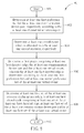
- Fig. 8 is a flowchart of a process 80 according to an example of the present invention.
- the process 80 can be utilized in the network shown in Fig. 1 , for realizing step 304 in the process 30.
- the process 80 may be compiled into the program code 214 and includes the following steps: Step 800: Start.
- Step 802 Determine at least one first preference list for the at least one communication device pair, respectively, according to the at least one channel information report.
- Step 804 Determine at least one virtual owner which is allocated with the at least one second resource, respectively.
- the above method is related to an example where there are one or more available resources at the network. Thus, virtual owners are needed for those available resources.
- the network may continue to handle the rest of the communication device pairs according the preference lists according to the following steps, if the rest of the communication device pairs are not part of the closed cycles.
- the network removes the at least one first directed edge and the at least one first closed cycle from the first graph, to determine a second graph comprising at least one second set of the at least one communication device pair.
- the network determines at least one second directed edge in the second graph according to the at least one preference list.
- the network determines at least one second set of the at least one resource exchange according to at least one second closed cycle comprising at least one set of the at least one second directed edge and at least one second set of the at least one communication device pair. Since the method where no virtual owner exists can be obtained from the method without considering the virtual owner and its preference list, detail of the method should readily be obtained by those skilled in the art and is not narrated herein.
- the network can determine a resource exchange ⁇ (CDP1, CDP2), (CDP2, VO1) ⁇ according to the directed edges forming a closed cycle, as shown in the right-hand side of Fig. 9 . Then, the network removes the closed cycle including the communication device pairs CDP1-CDP2, the virtual owner V01 and the corresponding directed edges from the graph.
- the network determines directed edges for the remaining communication device and the remaining virtual owner according to the preference lists as follows.
- the communication device pair CDP3 and the virtual owner V02 both emit directed edges to the communication device pair CDP3, according to the preference lists of the communication device pair CDP3 and the virtual owner V02 in the table 100.
- a graph including the communication device pair CDP3, the virtual owner V02 and the corresponding directed edges is formed. Since the communication device pair CDP3 emits the directed edge to itself, the directed edge is considered as a closed cycle. That is, the communication device pair CDP3 already has the most preferred resource which is the resource R3.
- the network can determine a resource exchange ⁇ (CDP3, CDP3) ⁇ which means no resource exchange according to the directed edge forming the closed cycle. Then, the network removes the closed cycle including the communication device pair CDP3 from the graph. In addition, the network further determines a resource exchange ⁇ (VO2, VO2) ⁇ since only the virtual owner V02 is left.
- the network may determine a resource exchange between a virtual owner and another virtual owner frequently in certain situations.
- the resource exchange between the virtual owners is not efficient, since resources of the virtual owners are actually owned by the network.
- a resource exchange between the virtual owners brings no benefit to the communication device pairs.
- the network may determine that in a preference list of a virtual owner, a priority of a resource of a communication device pair is higher than a priority of a resource at the network. That is, in a preference list of a virtual owner, priorities of resources of communication device pairs are higher than priorities of resources of virtual owners.
- the virtual owner will exchange its resource with a communication device pair with a higher probability. Accordingly, there are more opportunities for a communication device pair to exchange its resource with a virtual owner.
Landscapes
- Engineering & Computer Science (AREA)
- Computer Networks & Wireless Communication (AREA)
- Signal Processing (AREA)
- Quality & Reliability (AREA)
- Mobile Radio Communication Systems (AREA)
Abstract
Description
- The present invention relates to a method of handling a resource exchange and related communication device.
- In traditional communication systems, especially wireless communication systems, two communication devices communicate with each other via a base station, i.e., the base station is an intermediate entity between the communication devices. Such a scenario is inefficient in aspects of coverage area, resource utilization and transmission delay, especially when the communication devices are close to each other and are able to communicate with each other directly.
- Thus, device-to-device (D2D) communication is proposed, and a coverage area of the base station, the resource utilization and/or the transmission delay may thus be improved. For example, the D2D communication may be realized, after an initialization (e.g., connection establishment and/or peer discovery) is assisted by the base station. Then, two nearby communication devices may communicate (e.g., transmitting/receiving packets) with each other directly according to the D2D communication, and the base station does not need to forwards the packets transmitted between the communication devices.
- However, resource allocation for the traditional communication systems cannot be applied to the D2D communication because characteristics of the D2D communication are different from those of the traditional communication systems. Thus, a new resource allocation is needed for the D2D communication.
- In addition, the ad-hoc characteristic of the D2D communication introduces a new problem to the resource allocation: truth-telling issue. In more detail, information fed back from communication devices involved in the D2D communication (hereinafter the D2D pair for short) should be honest for the network to allocate the resource efficiently and correctly. However, it is difficult for the network to validate the information because the D2D communications only occur within the D2D pair (or the D2D devices). Thus, the D2D pair may thus be motivated to feed back fake information when the fake information may bring advantages to the D2D pair from the resource allocation. The above situations may happen, when the D2D pair or users of the D2D pair are rational (e.g., selfish). Thus, a problem of the fake information fed back by the D2D pair should be solved.
- The present invention therefore provides a method and related communication device for handling a resource exchange to solve the abovementioned problems.
- This is achieved by a method and a communication device for handing a resource exchange according to the independent claims here below. The dependent claims pertain to corresponding further developments and improvements.
- As will be seen more clearly from the detailed description following below, the claimed method of handling a resource exchange for a network comprises the steps of receiving at least one channel information report transmitted by at least one communication device pair, respectively; determining at least one resource exchange according to the at least one channel information report; and performing the at least one resource exchange on at least one first resource allocated to the at least one communication device pair and on at least one available resource at the network, to allocate at least one second resource to the at least one communication device pair.
-
-
Fig. 1 is a schematic diagram of a wireless communication system according to an example of the present invention. -
Fig. 2 is a schematic diagram of a communication device according to an example of the present invention. -
Fig. 3 is a flowchart of a process according to an example of the present invention. -
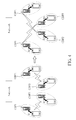
Fig. 4 is a schematic diagram of a resource exchange according to an example of the present invention. -
Fig. 5 is a schematic diagram of a resource exchange according to an example of the present invention. -
Fig. 6 is a set of flowcharts of processes according to an example of the present invention. -
Fig. 7 is a flowchart of a process according to an example of the present invention. -
Fig. 8 is a flowchart of a process according to an example of the present invention. -
Fig. 9 is a schematic diagram of a resource exchange according to an example of the present invention. -
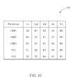
Fig. 10 is a table including preference lists of communication device pairs and virtual owners according to an example of the present invention. -
Fig. 1 is a schematic diagram of awireless communication system 10 according to an example of the present invention. Thewireless communication system 10 is briefly composed of a network and a plurality of communication devices. InFig. 1 , the network and the communication devices are simply utilized for illustrating the structure of thewireless communication system 10. In practice, the network can be the universal terrestrial radio access network (UTRAN) comprising a plurality of Node-Bs (NBs) in a universal mobile telecommunications system (UMTS). In another example, the network can be an evolved UTRAN (E-UTRAN) comprising a plurality of evolved NBs (eNBs) and/or relays in a long term evolution (LTE) system, a LTE-Advanced (LTE-A) system or an evolution of the LTE-A system. In another example, the network may be a base station in a wireless communication system conforming to wireless standards such as IEEE 802.11, IEEE 802.16, etc. - In addition, two communication devices may communicate with each other directly, after an initialization (e.g., connection establishment and/or peer discovery) is assisted by the network. That is, the communication devices may communicate (e.g., transmitting/receiving packets) with each other according to a device-to-device (D2D) communication, and the communication devices can be denoted as a communication device pair (i.e., a D2D pair) in this situation. Then, interferences (e.g., intra-area interferences and/or inter-area interferences) experienced by the communication devices in the same D2D pair may be similar.
- It should be noted that a cell controlled by the network may be divided into one or more service areas. Resources dedicated for the D2D communication may be reused in different service areas to improve resource utilization, while communication device pairs in the same service area can be allocated with different resources to avoid intra-area interference. For example, the communication devices in
Fig. 1 may be in a service area of a cell controlled by the network. In another example, the communication devices inFig. 1 may be in multiple service areas of a cell controlled by the network. The communication device pairs may still be affected by inter-area interference caused by communication device pairs in other service areas or inter-cell interference caused by communication device pairs in other cells allocated with the same resources. In certain situations, a distance between two communication devices in a communication device pair may be significantly smaller than a distance between two communication device pairs, wherein the communication device pairs may in the same or different service areas. - Furthermore, the network can also include both the UTRAN/E-UTRAN and a core network, wherein the core network includes network entities such as Mobility Management Entity (MME), Serving Gateway (S-GW), Packet Data Network (PDN) Gateway (P-GW), Self-Organizing Networks (SON) server and/or Radio Network Controller (RNC), etc. In other words, after the network receives information transmitted by a communication device, the information may be processed only by the UTRAN/E-UTRAN and decisions corresponding to the information are made at the UTRAN/E-UTRAN. Alternatively, the UTRAN/E-UTRAN may forward the information to the core network, and the decisions corresponding to the information are made at the core network after the core network processes the information. Besides, the information can be processed by both the UTRAN/E-UTRAN and the core network, and the decisions are made after coordination and/or cooperation are performed by the UTRAN/E-UTRAN and the core network. A communication device can be a user equipment (UE), a machine type communication (MTC) device, a mobile phone, a laptop, a tablet computer, an electronic book or a portable computer system. Besides, the network and the communication device can be seen as a transmitter or a receiver according to direction, e.g., for an uplink (UL), the communication device is the transmitter and the network is the receiver, and for a downlink (DL), the network is the transmitter and the communication device is the receiver.
-
Fig. 2 is a schematic diagram of acommunication device 20 according to an example of the present invention. Thecommunication device 20 can be a communication device or the network shown inFig. 1 , but is not limited herein. Thecommunication device 20 may include a processing means 200 such as a microprocessor or Application Specific Integrated Circuit (ASIC), astorage unit 210 and acommunication interfacing unit 220. Thestorage unit 210 may be any data storage device that can store aprogram code 214, accessed and executed by the processing means 200. Examples of thestorage unit 210 include a subscriber identity module (SIM), read-only memory (ROM), flash memory, random-access memory (RAM), CD-ROM/DVD-ROM, magnetic tape, hard disk and optical data storage device. Thecommunication interfacing unit 220 is preferably a transceiver and is used to transmit and receive signals (e.g., messages or packets) according to processing results of the processing means 200. -
Fig. 3 is a flowchart of aprocess 30 according to an example of the present invention. Theprocess 30 can be utilized in the network shown inFig. 1 , for handing a resource exchange. Theprocess 30 may be compiled into theprogram code 214 and includes the following steps:Step 300: Start. Step 302: Receive at least one channel information report transmitted by at least one communication device pair, respectively. Step 304: Determine at least one resource exchange according to the at least one channel information report. Step 306: Perform the at least one resource exchange on at least one first resource allocated to the at least one communication device pair and on at least one available resource at the network, to allocate at least one second resource to the at least one communication device pair. Step 308: End. - According to the
process 30, the network receives at least one channel information report (e.g., channel quality report, channel quality indicator (CQI)) transmitted by at least one communication device pair, respectively, and determines at least one resource exchange according to the at least one channel information report. Then, the network performs the at least one resource exchange on at least one first resource allocated to the at least one communication device pair and on at least one available resource at the network, to allocate at least one second resource to the at least one communication device pair. In other words, the network coordinates one or more resource exchanges within the communication device pairs and the network according to the channel information reports fed back by the communication device pairs. Note that a resource mentioned above can be one or more resource block groups (RBGs) in the 3rd Generation Partnership Project (3GPP) standard. In addition, the at least one first resource and the at least one second resource may be a plurality of resources dedicated for a D2D communication. The resource exchanges may only be performed within the communication device pairs, if no resource is available at the network. Thus, throughputs of the communication device pairs can be improved after suitable resources (e.g., with fewer interferences) are allocated (e.g., reallocated) to the communication device pairs. - Realization of the present invention is not limited to the above description.
-
Fig. 4 is a schematic diagram of a resource exchange according to an example of the present invention, wherein communication device pairs CDP1-CDP4 and the network are considered. At first, the communication device pairs CDP1-CDP2 both perform transmissions and/or receptions by using a resource R1, and the communication device pairs CDP3-CDP4 both perform transmissions and/or receptions by using a resource R2. The communication device pairs CDP1-CDP2 may both suffer large interferences, since the communication device pairs CDP1-CDP2 are close to each other and use the same resource R1. Similarly, the communication device pairs CDP3-CDP4 may both suffer large interferences, since the communication device pairs CDP3-CDP4 are close to each other and use the same resource R2. Thus, the network may determine a resource exchange, after receiving channel information reports transmitted by the communication device pairs CDP1-CDP4. As shown inFig. 4 , the resource exchange is that the resources of the communication device pairs CDP2-CDP3 are exchanged. The network may perform the resource exchange on the resources R1-R2 by indicating the resource exchange to the communication device pairs CDP2-CDP3 via a DL control channel (e.g., physical DL control channel (PDCCH)). That is, the network allocates the resources R1-R2 to the communication device pairs CDP3 and CDP2, respectively. In addition, the network may also indicate the communication device pairs CDP1 and CDP4 to keep using the same resources. Then, the communication device pair CDP2 can perform the transmissions/receptions by using the resource R2, and the communication device pair CDP3 can perform the transmissions/receptions by using the resource R1. Since the communication device pairs CDP1-CDP4 are now far from the communication device pairs CDP3, CDP4, CDP1 and CDP2 (i.e., the interfering sources), respectively, the interferences suffered by the communication device pairs CDP1-CDP4 are reduced. Thus, throughputs of the communication device pairs CDP1-CDP4 can be improved. - Note that the communication device pairs CDP2-CDP3 exchange the resources with each other in the above example. In another example, the communication device pairs CDP2-CDP3 may exchange the resources with the network.
-
Fig. 5 is a schematic diagram of a resource exchange according to an example of the present invention, wherein communication device pairs CDP1-CDP4 and the network are considered. At first, the communication device pairs CDP1-CDP2 both perform transmissions and/or receptions by using a resource R1, and the communication device pairs CDP3-CDP4 both perform transmissions and/or receptions by using a resource R2. In addition, a resource R3 is available at the network, and is free to being allocated to a communication device pair. The communication device pairs CDP1-CDP2 may both suffer large interferences, since the communication device pairs CDP1-CDP2 are close to each other and use the same resource R1. Similarly, the communication device pairs CDP3-CDP4 may both suffer large interferences, since the communication device pairs CDP3-CDP4 are close to each other and use the same resource R2. Thus, the network may determine a resource exchange {(CDP3, CDP2), (CDP2, network)}, after receiving channel information reports transmitted by the communication device pairs CDP1-CDP4. - As shown in
Fig. 5 , the resource exchange is that the resources of the communication device pairs CDP2-CDP3 and the network are exchanged. The network may perform the resource exchange on the resources R1-R3 by indicating the resource exchange to the communication device pairs CDP2-CDP3 via a DL control channel (e.g., PDCCH). That is, the network allocates the resources R1 and R3 to the communication device pairs CDP3 and CDP2, respectively. In addition, the network may also indicate the communication device pairs CDP1 and CDP4 to keep using the same resources. Then, the communication device pair CDP2 can perform the transmissions/receptions by using the resource R3, and the communication device pair CDP3 can perform the transmissions/receptions by using the resource R1. Since the communication device pairs CDP1 and CDP3 are now far from the communication device pairs CDP3 and CDP1 (i.e., the interfering sources), respectively, the interferences suffered by the communication device pairs CDP1 and CDP3 are reduced. In addition, the communication device pairs CDP2 and CDP4 suffer no interference now. Thus, throughputs of the communication device pairs CDP1-CDP4 can be improved. - A time instant at which a resource exchange is triggered is not limited herein. For example, a resource exchange can be triggered by the network, when a new communication device pair enters a coverage area (e.g., service area) of the network. In another example, a resource exchange can be triggered by the network, when a communication device pair requests a resource from the network. In another example, a resource exchange can be triggered by the network, when a grant of a resource allocated a communication device pair is terminated (e.g., expired) and the resource is returned to the network. In another example, a resource exchange can be triggered by the network, when one or more communication device pairs update channel information reports. The network may start to determine a resource exchange, when one or more of the above situations occur.
-
Fig. 6 is a set of flowcharts of processes according to an example of the present invention. The network and communication device pairs CDP1 and CDP2 are shown inFig. 6 . The network may transmit two grants to the communication device pairs CDP1 and CDP2, respectively, to initiate a resource exchange (e.g., via PDCCH(s)) (step 600), when the resource exchange is triggered by the network. The communication device pairs CDP1 and CDP2 may reply acknowledgements to the network to respond the grants (e.g., via physical UL control channel(s) (PUCCH(s))) (e.g., to agree the resource exchange) (step 602), after receiving the grants. In another example, a resource exchange can be triggered by a communication pair, e.g., the communication device pair CDP2. In this situation, the communication device pair CDP2 transmits an exchange request to the communication device pair CDP1 first (step 604), to initiate a resource exchange. The communication device pair CDP1 transmits an exchange response to the communication device pair CDP2 to respond the exchange request (e.g., to agree the resource exchange) (step 606), after receiving the exchange request. The communication device pair CDP2 may further reply an acknowledgement to the communication device CDP1 to respond the exchange response (step 608), after receiving the exchange response. Then, both of the communication device pairs CDP1 and CDP2 transmit an update of the ownership of the resources to the network (e.g., via PUCCH(s)) (step 610), such that the network can know the result of the resource exchange. - A D2D communication can be initialized according to various methods.
-
Fig. 7 is a flowchart of a process according to an example of the present invention. The network and a communication device pair CDP which includes two communication devices CD1 and CD2 are shown inFig. 7 . The communication device pair CDP may be identified via performing a peer discovery. Then, one of the communication devices CD1 and CD2 (e.g., the communication device CD1 which may be a head of the communication device pair) triggers a resource granting procedure by transmitting a D2D scheduling request (SR) (e.g., via a dedicated SR resource in a PUCCH) to the network (step 700). The network may transmit a resource grant for requesting channel information reports (e.g., CQIs) and buffer status reports (BSRs) to both of the communication devices CD1 and CD2 (e.g., via PDCCH(s)) if there are unallocated resources at the network (step 702), after receiving the D2D scheduling request. The communication devices CD1 and CD2 may transmit the channel information reports and the BSRs to the network via UL resources (e.g., physical UL shared channel(s) (PUSCH(s))) indicated in the resource grant (step 704). For example, a channel information report may include measurement results related to dedicated resources (e.g., subcarriers) for the D2D communication. In addition, a BSR may include a Quality of Service (QoS) requirement of the communication device pair CDP. Thus, the network can determine an amount of resources reserved for the communication device pair CDP according to the BSR. For example, the network may reserve a specific resource in several frames for the communication device pair CDP according to the BSR. The amount of resource reserved for the D2D communication may be determined according to the expectations in the traffic loading of the system. Finally, the network transmits a resource grant for performing the D2D communication to the communication devices CD1 and CD2 (e.g., via PDCCH(s)) (step 706). Preferably, the network should maintain up-to-date information of channel qualities experienced by the communication device pair CDP. Updates of the channel qualities may be triggered by the network or the communication device pair CDP. A procedure for updating the channel qualities (i.e., the transmission of the channel information reports) is similar to the first part of the procedure for initializing the D2D communication, and is not narrated herein. - A D2D communication can be performed on an unlicensed band or a licensed band. Although an existing wireless technology such as Wi-Fi and Bluetooth can be used for realizing the D2D communication in the unlicensed band, it is relatively unreliable due to interference caused by other devices operating in the same band. On the other hand, dedicated resources for the D2D communication may be allocated (e.g., reserved) to avoid (or to reduce) the interference, if the licensed band is used. For either of the above examples, the network may perform a resource allocation for the D2D communication according to one or more of the following criterions:
- (1) preventing communication device pairs and/or other communication devices from being affected by interference caused by the D2D communication;
- (2) improving efficiency of the resource allocation according to channel conditions;
- (3) reusing time resources and/or frequency resources; and
- (4) responding timely the requests from communication device pairs, rapid changes in inter/intra-cell interference and/or network reconfigurations.
- It should be noted that advantages of the present invention include but are not limited to, what here follows. The present invention can be easily applied to communication systems with structures including a network and one or more communication devices, e.g., Terrestrial Trunked Radio (TETRA), WLAN (e.g., HiperLAN/2 or 802.11), UMTS, LTE, LTE-A, etc. The present invention can be realized flexibly (e.g., in configuration and/or deployment) according to various service/system requirements.
- The network may realize
step 304 in theprocess 30 by determining at least one first performance metric corresponding to the at least one first resource and at least one second performance metric corresponding to the at least one second resource according to the at least one channel information report and determining the at least one resource exchange according to the at least one first performance metric and the at least one second performance metric. That is, the network determines performance metrics according to the channel information reports. Then, the network determines the resource exchanges according to the performance metrics. For example, the performance metrics mentioned above may be interferences. In this situation, the performance metrics corresponding to the current resource allocation should not be better (e.g., not be lower) than the performance metrics corresponding to the resource allocation determined according to the resource exchange. Preferably, for each of the communication device pairs involved in the resource exchange, a performance metric corresponding to a resource currently owned by a communication device pair should not be better than a performance metric corresponding to a resource to be allocated to the communication device pair according to the resource exchange. That is, the resource exchange should be beneficial (i.e., remaining the same or becoming better) for each of the communication device pairs. The resource exchanged is termed as a beneficial exchange, if the above description is realized. In another example, the performance metrics mentioned above may be delays and/or bandwidths, and are not limited herein. -
Fig. 8 is a flowchart of aprocess 80 according to an example of the present invention. Theprocess 80 can be utilized in the network shown inFig. 1 , for realizingstep 304 in theprocess 30. Theprocess 80 may be compiled into theprogram code 214 and includes the following steps:Step 800: Start. Step 802: Determine at least one first preference list for the at least one communication device pair, respectively, according to the at least one channel information report. Step 804: Determine at least one virtual owner which is allocated with the at least one second resource, respectively. Step 806: Determine a first graph comprising at least one first directed edge, the at least one communication device pair and the at least one virtual owner, wherein the at least one first directed edge is determined according to the at least one first preference list and at least one second preference list of the at least one virtual owner. Step 808: Determine at least one first set of the at least one resource exchange according to at least one first closed cycle comprising at least one set of the at least one first directed edge, at least one first set of the at least one communication device pair and/or at least one first set of the at least one virtual owner. Step 810: End. - According to the
process 80, the network determines at least one first preference list for the at least one communication device pair, respectively, according to the at least one channel information report. Then, the network determines at least one virtual owner (i.e., trader) which is allocated with the at least one second resource, respectively. In addition, the network determines a first graph comprising at least one first directed edge, the at least one communication device pair and the at least one virtual owner, wherein the at least one first directed edge is determined according to the at least one first preference list and at least one second preference list of the at least one virtual owner. Finally, the network determines at least one first set of the at least one resource exchange according to at least one first closed cycle comprising at least one set of the at least one first directed edge, at least one first set of the at least one communication device pair and/or at least one first set of the at least one virtual owner. In theprocess 80, a preference list of a communication device pair includes at least one resource prioritized for the communication device pair, and a preference list of a virtual owner includes at least one resource prioritized for the virtual owner. In addition, a communication device pair emits only a directed edge to a corresponding communication device pair or a corresponding virtual owner, and a virtual owner emits only a directed edge to a corresponding communication device pair or a corresponding virtual owner. - The network may continue to handle the rest of the communication device pairs according the preference lists according to the following steps, if the rest of the communication device pairs are not part of the closed cycles. The network removes the at least one first directed edge and the at least one first closed cycle from the first graph, to determine a second graph comprising at least one second set of the at least one communication device pair and/or at least one second set of the at least one virtual owner. The network determines at least one second directed edge in the second graph according to the at least one first preference list and the at least one second preference list. Then, the network determines at least one second set of the at least one resource exchange according to at least one second closed cycle comprising at least one set of the at least one second directed edge, at least one second set of the at least one communication device pair and/or at least one second set of the at least one virtual owner.
- In other words, for each communication device pair (i.e., vertex), the network determines (i.e., generates) a directed edge from a communication device pair to a target communication device pair according to a preference list of the communication device pair. Accordingly, a graph including communication device pairs and directed edges is formed. Preferably, the network may determine a directed edge from a communication device pair to a target communication device pair having the most preferred resource in a preference list of the communication device pair, when the graph is formed.
- Then, the network searches closed cycles in the graph. There should be at least one closed cycle because each communication device pair emits only one directed edge. For each closed cycle, the network determines that the communication device pairs in the closed cycle exchange their resources with each other according to the directed edges of the closed cycle. That is, resource exchanges between communication device pairs in a closed cycle can be determined according to directed edges of the closed cycle. Then, the network removes the communication device pairs with the corresponding closed cycle from the graph. In addition, it is possible that the network generates a directed edge from a communication device pair to the communication device pair itself. For example, the communication device pair already has the most preferred resource. In such a case, the network can remove the communication device pair from the graph. That is, a directed edge is also considered as a closed cycle, if the source vertex and the destination vertex are the same.
- Similarly, for each of remaining communication device pairs, the network generates a directed edge from a communication device pair to a target communication device pair according to a preference list of the communication device pair. Accordingly, a new graph including the remaining communication device pairs and directed edges is formed. Note that the network may generate a directed edge from a communication device pair to a target communication device pair having the second preferred resource in a preference list of the communication device pair, when the target communication device pair having the most preferred resource in the preference list of the communication device pair is removed. In other words, a directed edge from a communication device pair to a target communication device pair is determined according to a preference list of the communication device pair and communication device pairs (i.e., resources) remained in the present graph. As can be seen, the directed edges of the remaining communication device pairs in the present graph may be different from the directed edges of the remaining communication device pairs in the previous graph, since some communication device pairs were removed in the previous graph.
- Then, the network searches closed cycles in the graph according to the previous description, and is not narrated herein. Similarly, for each closed cycle, resource exchanges between communication device pairs in a closed cycle can be determined according to directed edges of the closed cycle. The network continues the above process until all the communication device pairs are removed or only a single communication device pair is left. Thus, resource exchanges for all the communication device pairs are determined. The network is able to perform the resource exchanges on the resources, to allocate (or reallocate) the resources.
- The above method is related to an example where there are one or more available resources at the network. Thus, virtual owners are needed for those available resources.
- On the other hand, the method can also be applied to the case where there is no available resource at the network, after some modifications are made. In this situation, no virtual owner is needed to be created. That is, the
process 80 can be modified to realizestep 304 in theprocess 30 as follows. The network determines at least one preference list for the at least one communication device pair, respectively, according to the at least one channel information report. In addition, the network determines a first graph comprising at least one first directed edge and the at least one communication device pair, wherein the at least one first directed edge is determined according to the at least one preference list. Finally, the network determines at least one first set of the at least one resource exchange according to at least one first closed cycle comprising at least one set of the at least one first directed edge and at least one first set of the at least one communication device pair. In addition, a preference list of a communication device pair comprises at least one resource prioritized for the communication device pair, and a communication device pair emits only a directed edge to a corresponding communication device pair. - The network may continue to handle the rest of the communication device pairs according the preference lists according to the following steps, if the rest of the communication device pairs are not part of the closed cycles. The network removes the at least one first directed edge and the at least one first closed cycle from the first graph, to determine a second graph comprising at least one second set of the at least one communication device pair. The network determines at least one second directed edge in the second graph according to the at least one preference list. Then, the network determines at least one second set of the at least one resource exchange according to at least one second closed cycle comprising at least one set of the at least one second directed edge and at least one second set of the at least one communication device pair. Since the method where no virtual owner exists can be obtained from the method without considering the virtual owner and its preference list, detail of the method should readily be obtained by those skilled in the art and is not narrated herein.
-
Fig. 9 is a schematic diagram of a resource exchange according to an example of the present invention, wherein communication device pairs CDP1-CDP3 and the network are considered. In addition, the communication device pairs CDP1-CDP3 own resources R1-R3, respectively, and resources R4-R5 are available at the network. Further, the network determines that virtual owners V01-V02 own the resources R4-R5, respectively. Fig. 108 is a table 100 including preference lists of communication device pairs and virtual owners according to an example of the present invention. For example, a preference list of the communication device pair CDP1 indicates that the preferences regarding the resources from high to low are the resources R2, R1, R3, R4 and R5. The network may determine the table 100 according to channel information reports transmitted by the communication devices pair CDP1-CDP3. - In the first step, the network determines directed edges according to the preference lists as follows. The communication device pairs CDP1-CDP3 emit directed edges to the communication device pair CDP2, the virtual owner V01 and the communication device pair CDP2, respectively, according to the preference lists of the communication device pairs CDP1-CDP3 in the table 100. The virtual owners V01-V02 emit directed edges to the communication device pair CDP1 and the communication device pair CDP2, respectively, according to the preference lists of the virtual owners V01-V02 in the table 100. Thus, a graph including the communication device pairs CDP1-CDP3, the virtual owners V01-V02 and the corresponding directed edges is formed. The network can determine a resource exchange {(CDP1, CDP2), (CDP2, VO1)} according to the directed edges forming a closed cycle, as shown in the right-hand side of
Fig. 9 . Then, the network removes the closed cycle including the communication device pairs CDP1-CDP2, the virtual owner V01 and the corresponding directed edges from the graph. - In the second step, the network determines directed edges for the remaining communication device and the remaining virtual owner according to the preference lists as follows. The communication device pair CDP3 and the virtual owner V02 both emit directed edges to the communication device pair CDP3, according to the preference lists of the communication device pair CDP3 and the virtual owner V02 in the table 100. Thus, a graph including the communication device pair CDP3, the virtual owner V02 and the corresponding directed edges is formed. Since the communication device pair CDP3 emits the directed edge to itself, the directed edge is considered as a closed cycle. That is, the communication device pair CDP3 already has the most preferred resource which is the resource R3. The network can determine a resource exchange {(CDP3, CDP3)} which means no resource exchange according to the directed edge forming the closed cycle. Then, the network removes the closed cycle including the communication device pair CDP3 from the graph. In addition, the network further determines a resource exchange {(VO2, VO2)} since only the virtual owner V02 is left.
- As can be seen, all the resource exchanges are determined, and a resource allocation can be performed according to the resource exchanges.
- It should be noted that a preference list of a virtual owner can be determined according to various methods. For example, the preference list of the virtual owner can be determined according to preference lists of communication device pairs. In one example, the virtual owner can emit a directed edge to a communication device pair such that a closed cycle can be formed. Preferably, the closed cycle is the largest cycle in a graph such that more communication device pairs and/or virtual owners can be removed from the graph. In another example, the preference list of the virtual owner can be determined randomly.
- However, the network may determine a resource exchange between a virtual owner and another virtual owner frequently in certain situations. The resource exchange between the virtual owners is not efficient, since resources of the virtual owners are actually owned by the network. Thus, a resource exchange between the virtual owners brings no benefit to the communication device pairs. To mitigate this problem, the network may determine that in a preference list of a virtual owner, a priority of a resource of a communication device pair is higher than a priority of a resource at the network. That is, in a preference list of a virtual owner, priorities of resources of communication device pairs are higher than priorities of resources of virtual owners. Thus, the virtual owner will exchange its resource with a communication device pair with a higher probability. Accordingly, there are more opportunities for a communication device pair to exchange its resource with a virtual owner.
- In addition, a communication device pair may perform a transmission and/or a reception with the network, as stated in the above description. A method according to which the communication device pair performs the transmission and/or the reception is not limited herein. For example, a head (e.g., leader or group owner) of the communication device pair may perform the transmission and/or the reception with the network, if the communication device pair intends to communicate with the network. In another example, either one of communication devices in the communication device pair may perform the transmission and/or the reception with the network, if the communication device pair intends to communicate with the network.
- Those skilled in the art should readily make combinations, modifications and/or alterations on the abovementioned description and examples. The abovementioned steps of the processes including suggested steps can be realized by means that could be a hardware, a firmware known as a combination of a hardware device and computer instructions and data that reside as read-only software on the hardware device, or an electronic system. Examples of hardware can include analog, digital and mixed circuits known as microcircuit, microchip, or silicon chip. Examples of the electronic system can include a system on chip (SOC), system in package (SiP), a computer on module (COM), and the
communication device 20. - To sum up, the present invention provides a method of handling resource exchange. Thus, throughputs of the communication device pairs can be improved after suitable resources (e.g., with fewer interferences) are allocated (e.g., reallocated) to the communication device pairs.
Claims (15)
- A method of handling a resource exchange for a network characterized by the method comprising the steps of:receiving at least one channel information report transmitted by at least one communication device pair, respectively (302);determining at least one resource exchange according to the at least one channel information report (304); andperforming the at least one resource exchange on at least one first resource allocated to the at least one communication device pair and on at least one available resource at the network, to allocate at least one second resource to the at least one communication device pair (306).
- The method of claim 1, characterized in that the step of determining the at least one resource exchange according to the at least one channel information report comprises the step of:determining at least one first performance metric corresponding to the at least one first resource and at least one second performance metric corresponding to the at least one second resource according to the at least one channel information report; anddetermining the at least one resource exchange according to the at least one first performance metric and the at least one second performance metric.
- The method of claim 2, characterized in that the at least one first performance metric is not lower than the at least one second performance metric, respectively.
- The method of claim 2, characterized in that the at least one first performance metric and the at least one second performance metric comprise a plurality of interferences.
- The method of claim 1, characterized in that the step of determining the at least one resource exchange according to the at least one channel information report comprises the step of:determining at least one first preference list for the at least one communication device pair, respectively, according to the at least one channel information report;determining at least one virtual owner which is allocated with the at least one second resource, respectively;determining a first graph comprising at least one first directed edge, the at least one communication device pair and the at least one virtual owner, wherein the at least one first directed edge is determined according to the at least one first preference list and at least one second preference list of the at least one virtual owner; anddetermining at least one first set of the at least one resource exchange according to at least one first closed cycle comprising at least one set of the at least one first directed edge, at least one first set of the at least one communication device pair and/or at least one first set of the at least one virtual owner;wherein a preference list of a communication device pair comprises at least one resource prioritized for the communication device pair, and a preference list of a virtual owner comprises at least one resource prioritized for the virtual owner;wherein a communication device pair emits only a directed edge to a corresponding communication device pair or a corresponding virtual owner, and a virtual owner emits only a directed edge to a corresponding communication device pair or a corresponding virtual owner.
- The method of claim 5, further comprising the steps of:removing the at least one first directed edge and the at least one first closed cycle from the first graph, to determine a second graph comprising at least one second set of the at least one communication device pair and/or at least one second set of the at least one virtual owner;determining at least one second directed edge in the second graph according to the at least one first preference list and the at least one second preference list; anddetermining at least one second set of the at least one resource exchange according to at least one second closed cycle comprising at least one set of the at least one second directed edge, at least one second set of the at least one communication device pair and/or at least one second set of the at least one virtual owner.
- The method of claim 5, characterized in that the at least one second preference list is determined according to the at least one first preference list.
- The method of claim 5, characterized in that the at least one second preference list is determined randomly.
- The method of claim 5, characterized in that in the preference list of the virtual owner, a priority of a resource of one of the at least one communication device pair is higher than a priority of a resource at the network.
- The method of claim 1, characterized in that the step of determining the at least one resource exchange according to the at least one channel information report comprises the step of:determining at least one preference list for the at least one communication device pair, respectively, according to the at least one channel information report;determining a first graph comprising at least one first directed edge and the at least one communication device pair, wherein the at least one first directed edge is determined according to the at least one preference list; anddetermining at least one first set of the at least one resource exchange according to at least one first closed cycle comprising at least one set of the at least one first directed edge and at least one first set of the at least one communication device pair;wherein a preference list of a communication device pair comprises at least one resource prioritized for the communication device pair, and a communication device pair emits only a directed edge to a corresponding communication device pair.
- The method of claim 10, further comprising the steps of:removing the at least one first directed edge and the at least one first closed cycle from the first graph, to determine a second graph comprising at least one second set of the at least one communication device pair;determining at least one second directed edge in the second graph according to the at least one preference list; anddetermining at least one second set of the at least one resource exchange according to at least one second closed cycle comprising at least one set of the at least one second directed edge and at least one second set of the at least one communication device pair.
- The method of any of claims 1-11, characterized in that the at least one first resource and the at least one second resource are a plurality of resources dedicated for a device-to-device (D2D) communication.
- The method of any of claims 1-12, characterized in that the at least one first resource and the at least one available resource are different resources.
- The method of any of claims 1-13, characterized in that the at least one second resource does not comprise the at least one available resource.
- A communication device capable of handling a resource exchange according to any combination of claims 1-14.
Applications Claiming Priority (2)
| Application Number | Priority Date | Filing Date | Title |
|---|---|---|---|
| US201361771343P | 2013-03-01 | 2013-03-01 | |
| US14/191,386 US9602951B2 (en) | 2013-03-01 | 2014-02-26 | Method of handling resource exchange and related communication device |
Publications (2)
| Publication Number | Publication Date |
|---|---|
| EP2773158A1 true EP2773158A1 (en) | 2014-09-03 |
| EP2773158B1 EP2773158B1 (en) | 2018-08-29 |
Family
ID=50235931
Family Applications (1)
| Application Number | Title | Priority Date | Filing Date |
|---|---|---|---|
| EP14157010.1A Active EP2773158B1 (en) | 2013-03-01 | 2014-02-27 | Method of handling resource exchange and related communication device |
Country Status (4)
| Country | Link |
|---|---|
| US (1) | US9602951B2 (en) |
| EP (1) | EP2773158B1 (en) |
| CN (1) | CN104023359B (en) |
| TW (1) | TWI539855B (en) |
Families Citing this family (5)
| Publication number | Priority date | Publication date | Assignee | Title |
|---|---|---|---|---|
| US9844067B2 (en) * | 2013-07-11 | 2017-12-12 | Lg Electronics Inc. | Broadcasting method using device-to-device (D2D) communication in wireless communication system |
| US9756646B2 (en) * | 2014-04-18 | 2017-09-05 | Soongsil University Research Consortium Techno- Park | D2D communications system and allocation method of resources and power using the same |
| US11063645B2 (en) | 2018-12-18 | 2021-07-13 | XCOM Labs, Inc. | Methods of wirelessly communicating with a group of devices |
| US10756795B2 (en) | 2018-12-18 | 2020-08-25 | XCOM Labs, Inc. | User equipment with cellular link and peer-to-peer link |
| US11330649B2 (en) | 2019-01-25 | 2022-05-10 | XCOM Labs, Inc. | Methods and systems of multi-link peer-to-peer communications |
Citations (3)
| Publication number | Priority date | Publication date | Assignee | Title |
|---|---|---|---|---|
| US20090245085A1 (en) * | 2008-03-27 | 2009-10-01 | Zhifeng Tao | Graph-Based Method for Allocating Resources in OFDMA Networks |
| WO2011069295A1 (en) * | 2009-12-11 | 2011-06-16 | Nokia Corporation | Method, apparatus and computer program product for allocating resources in wireless communication network |
| WO2012159270A1 (en) * | 2011-05-25 | 2012-11-29 | Renesas Mobile Corporation | Resource allocation for d2d communication |
-
2014
- 2014-02-26 US US14/191,386 patent/US9602951B2/en active Active
- 2014-02-27 EP EP14157010.1A patent/EP2773158B1/en active Active
- 2014-02-27 TW TW103106850A patent/TWI539855B/en active
- 2014-03-03 CN CN201410074469.XA patent/CN104023359B/en active Active
Patent Citations (3)
| Publication number | Priority date | Publication date | Assignee | Title |
|---|---|---|---|---|
| US20090245085A1 (en) * | 2008-03-27 | 2009-10-01 | Zhifeng Tao | Graph-Based Method for Allocating Resources in OFDMA Networks |
| WO2011069295A1 (en) * | 2009-12-11 | 2011-06-16 | Nokia Corporation | Method, apparatus and computer program product for allocating resources in wireless communication network |
| WO2012159270A1 (en) * | 2011-05-25 | 2012-11-29 | Renesas Mobile Corporation | Resource allocation for d2d communication |
Non-Patent Citations (1)
| Title |
|---|
| SHAOYI XU ET AL: "Effective Interference Cancellation Scheme for Device-to-Device Communication Underlaying Cellular Networks", VEHICULAR TECHNOLOGY CONFERENCE FALL (VTC 2010-FALL), 2010 IEEE 72ND, IEEE, PISCATAWAY, NJ, USA, 6 September 2010 (2010-09-06), pages 1 - 5, XP031770548, ISBN: 978-1-4244-3573-9 * |
Also Published As
| Publication number | Publication date |
|---|---|
| TW201436627A (en) | 2014-09-16 |
| CN104023359B (en) | 2018-09-07 |
| US20140247779A1 (en) | 2014-09-04 |
| CN104023359A (en) | 2014-09-03 |
| US9602951B2 (en) | 2017-03-21 |
| EP2773158B1 (en) | 2018-08-29 |
| TWI539855B (en) | 2016-06-21 |
Similar Documents
| Publication | Publication Date | Title |
|---|---|---|
| TWI652962B (en) | Method and device for multi-uplink carrier data transmission in mobile communication | |
| CN107925497B (en) | Cellular communication method based on flexible frame structure and apparatus thereof | |
| TWI508580B (en) | Device handshake/discovery for inter-device communication in wireless communication systems | |
| TWI568207B (en) | System, method and apparatus for distributed scheduling for device-to-device interference mitigation | |
| US11082965B2 (en) | Resource allocation method and relevant device | |
| WO2020220910A1 (en) | Method and apparatus for handling sidelink reports | |
| WO2020087365A1 (en) | Methods and devices for sending and configuring sidelink data | |
| WO2020087785A1 (en) | Wireless communication method, terminal device and network device | |
| US11910407B2 (en) | Method for resource allocation in device to device communication | |
| US12581516B2 (en) | Resource selection in side link (SL) communications | |
| JP2024515822A (en) | Mobility management method and communication device | |
| US20240073875A1 (en) | Terminal device and method therein for resource reservation | |
| WO2018120065A1 (en) | Apparatus and method for configuring dynamic time division duplex, and communication system | |
| US12526836B2 (en) | Handling overlapping of multiple physical uplink shared channels (PUSCHs) | |
| CN113661772A (en) | Method and device for identifying user equipment context in edge link transmission | |
| EP2773158B1 (en) | Method of handling resource exchange and related communication device | |
| US20240430040A1 (en) | Terminal Devices, Network Devices, and Methods Thereof | |
| JP2022554261A (en) | Power allocation method and apparatus | |
| US20240172321A1 (en) | Methods, Node, UE and Computer Readable Media for Aligning Partial Sensing Configuration with DRX Configuration | |
| WO2020237526A1 (en) | Method, network device and network node for scheduling terminal devices | |
| CN105578494B (en) | Device-to-device interference coordination method and device, base station and user equipment | |
| US20220279558A1 (en) | Terminal device, network node and method for facilitating transmission of logical channels over sidelink | |
| EP4420448A1 (en) | Method for handling sidelink communication between user equipments using quality indications of sidelink carriers | |
| US11569947B2 (en) | Method and apparatus for managing a resource in a wireless communication system | |
| US20240080823A1 (en) | Method and network node for handling pucch resources in a frequency spectrum of the communications system |
Legal Events
| Date | Code | Title | Description |
|---|---|---|---|
| PUAI | Public reference made under article 153(3) epc to a published international application that has entered the european phase |
Free format text: ORIGINAL CODE: 0009012 |
|
| 17P | Request for examination filed |
Effective date: 20140227 |
|
| AK | Designated contracting states |
Kind code of ref document: A1 Designated state(s): AL AT BE BG CH CY CZ DE DK EE ES FI FR GB GR HR HU IE IS IT LI LT LU LV MC MK MT NL NO PL PT RO RS SE SI SK SM TR |
|
| AX | Request for extension of the european patent |
Extension state: BA ME |
|
| R17P | Request for examination filed (corrected) |
Effective date: 20150226 |
|
| RBV | Designated contracting states (corrected) |
Designated state(s): AL AT BE BG CH CY CZ DE DK EE ES FI FR GB GR HR HU IE IS IT LI LT LU LV MC MK MT NL NO PL PT RO RS SE SI SK SM TR |
|
| STAA | Information on the status of an ep patent application or granted ep patent |
Free format text: STATUS: EXAMINATION IS IN PROGRESS |
|
| 17Q | First examination report despatched |
Effective date: 20161028 |
|
| GRAP | Despatch of communication of intention to grant a patent |
Free format text: ORIGINAL CODE: EPIDOSNIGR1 |
|
| STAA | Information on the status of an ep patent application or granted ep patent |
Free format text: STATUS: GRANT OF PATENT IS INTENDED |
|
| INTG | Intention to grant announced |
Effective date: 20180329 |
|
| RIC1 | Information provided on ipc code assigned before grant |
Ipc: H04W 4/70 20180101ALI20180320BHEP Ipc: H04W 72/04 20090101AFI20180320BHEP Ipc: H04W 72/08 20090101ALN20180320BHEP |
|
| GRAS | Grant fee paid |
Free format text: ORIGINAL CODE: EPIDOSNIGR3 |
|
| GRAA | (expected) grant |
Free format text: ORIGINAL CODE: 0009210 |
|
| STAA | Information on the status of an ep patent application or granted ep patent |
Free format text: STATUS: THE PATENT HAS BEEN GRANTED |
|
| AK | Designated contracting states |
Kind code of ref document: B1 Designated state(s): AL AT BE BG CH CY CZ DE DK EE ES FI FR GB GR HR HU IE IS IT LI LT LU LV MC MK MT NL NO PL PT RO RS SE SI SK SM TR |
|
| REG | Reference to a national code |
Ref country code: GB Ref legal event code: FG4D |
|
| REG | Reference to a national code |
Ref country code: CH Ref legal event code: EP |
|
| REG | Reference to a national code |
Ref country code: AT Ref legal event code: REF Ref document number: 1036708 Country of ref document: AT Kind code of ref document: T Effective date: 20180915 |
|
| REG | Reference to a national code |
Ref country code: IE Ref legal event code: FG4D |
|
| REG | Reference to a national code |
Ref country code: DE Ref legal event code: R096 Ref document number: 602014031194 Country of ref document: DE |
|
| REG | Reference to a national code |
Ref country code: NL Ref legal event code: MP Effective date: 20180829 |
|
| REG | Reference to a national code |
Ref country code: LT Ref legal event code: MG4D |
|
| PG25 | Lapsed in a contracting state [announced via postgrant information from national office to epo] |
Ref country code: NL Free format text: LAPSE BECAUSE OF FAILURE TO SUBMIT A TRANSLATION OF THE DESCRIPTION OR TO PAY THE FEE WITHIN THE PRESCRIBED TIME-LIMIT Effective date: 20180829 Ref country code: SE Free format text: LAPSE BECAUSE OF FAILURE TO SUBMIT A TRANSLATION OF THE DESCRIPTION OR TO PAY THE FEE WITHIN THE PRESCRIBED TIME-LIMIT Effective date: 20180829 Ref country code: IS Free format text: LAPSE BECAUSE OF FAILURE TO SUBMIT A TRANSLATION OF THE DESCRIPTION OR TO PAY THE FEE WITHIN THE PRESCRIBED TIME-LIMIT Effective date: 20181229 Ref country code: BG Free format text: LAPSE BECAUSE OF FAILURE TO SUBMIT A TRANSLATION OF THE DESCRIPTION OR TO PAY THE FEE WITHIN THE PRESCRIBED TIME-LIMIT Effective date: 20181129 Ref country code: LT Free format text: LAPSE BECAUSE OF FAILURE TO SUBMIT A TRANSLATION OF THE DESCRIPTION OR TO PAY THE FEE WITHIN THE PRESCRIBED TIME-LIMIT Effective date: 20180829 Ref country code: NO Free format text: LAPSE BECAUSE OF FAILURE TO SUBMIT A TRANSLATION OF THE DESCRIPTION OR TO PAY THE FEE WITHIN THE PRESCRIBED TIME-LIMIT Effective date: 20181129 Ref country code: RS Free format text: LAPSE BECAUSE OF FAILURE TO SUBMIT A TRANSLATION OF THE DESCRIPTION OR TO PAY THE FEE WITHIN THE PRESCRIBED TIME-LIMIT Effective date: 20180829 Ref country code: FI Free format text: LAPSE BECAUSE OF FAILURE TO SUBMIT A TRANSLATION OF THE DESCRIPTION OR TO PAY THE FEE WITHIN THE PRESCRIBED TIME-LIMIT Effective date: 20180829 Ref country code: GR Free format text: LAPSE BECAUSE OF FAILURE TO SUBMIT A TRANSLATION OF THE DESCRIPTION OR TO PAY THE FEE WITHIN THE PRESCRIBED TIME-LIMIT Effective date: 20181130 |
|
| REG | Reference to a national code |
Ref country code: AT Ref legal event code: MK05 Ref document number: 1036708 Country of ref document: AT Kind code of ref document: T Effective date: 20180829 |
|
| PG25 | Lapsed in a contracting state [announced via postgrant information from national office to epo] |
Ref country code: LV Free format text: LAPSE BECAUSE OF FAILURE TO SUBMIT A TRANSLATION OF THE DESCRIPTION OR TO PAY THE FEE WITHIN THE PRESCRIBED TIME-LIMIT Effective date: 20180829 Ref country code: AL Free format text: LAPSE BECAUSE OF FAILURE TO SUBMIT A TRANSLATION OF THE DESCRIPTION OR TO PAY THE FEE WITHIN THE PRESCRIBED TIME-LIMIT Effective date: 20180829 Ref country code: HR Free format text: LAPSE BECAUSE OF FAILURE TO SUBMIT A TRANSLATION OF THE DESCRIPTION OR TO PAY THE FEE WITHIN THE PRESCRIBED TIME-LIMIT Effective date: 20180829 |
|
| PG25 | Lapsed in a contracting state [announced via postgrant information from national office to epo] |
Ref country code: IT Free format text: LAPSE BECAUSE OF FAILURE TO SUBMIT A TRANSLATION OF THE DESCRIPTION OR TO PAY THE FEE WITHIN THE PRESCRIBED TIME-LIMIT Effective date: 20180829 Ref country code: PL Free format text: LAPSE BECAUSE OF FAILURE TO SUBMIT A TRANSLATION OF THE DESCRIPTION OR TO PAY THE FEE WITHIN THE PRESCRIBED TIME-LIMIT Effective date: 20180829 Ref country code: ES Free format text: LAPSE BECAUSE OF FAILURE TO SUBMIT A TRANSLATION OF THE DESCRIPTION OR TO PAY THE FEE WITHIN THE PRESCRIBED TIME-LIMIT Effective date: 20180829 Ref country code: AT Free format text: LAPSE BECAUSE OF FAILURE TO SUBMIT A TRANSLATION OF THE DESCRIPTION OR TO PAY THE FEE WITHIN THE PRESCRIBED TIME-LIMIT Effective date: 20180829 Ref country code: CZ Free format text: LAPSE BECAUSE OF FAILURE TO SUBMIT A TRANSLATION OF THE DESCRIPTION OR TO PAY THE FEE WITHIN THE PRESCRIBED TIME-LIMIT Effective date: 20180829 Ref country code: EE Free format text: LAPSE BECAUSE OF FAILURE TO SUBMIT A TRANSLATION OF THE DESCRIPTION OR TO PAY THE FEE WITHIN THE PRESCRIBED TIME-LIMIT Effective date: 20180829 Ref country code: RO Free format text: LAPSE BECAUSE OF FAILURE TO SUBMIT A TRANSLATION OF THE DESCRIPTION OR TO PAY THE FEE WITHIN THE PRESCRIBED TIME-LIMIT Effective date: 20180829 |
|
| PG25 | Lapsed in a contracting state [announced via postgrant information from national office to epo] |
Ref country code: SM Free format text: LAPSE BECAUSE OF FAILURE TO SUBMIT A TRANSLATION OF THE DESCRIPTION OR TO PAY THE FEE WITHIN THE PRESCRIBED TIME-LIMIT Effective date: 20180829 Ref country code: DK Free format text: LAPSE BECAUSE OF FAILURE TO SUBMIT A TRANSLATION OF THE DESCRIPTION OR TO PAY THE FEE WITHIN THE PRESCRIBED TIME-LIMIT Effective date: 20180829 Ref country code: SK Free format text: LAPSE BECAUSE OF FAILURE TO SUBMIT A TRANSLATION OF THE DESCRIPTION OR TO PAY THE FEE WITHIN THE PRESCRIBED TIME-LIMIT Effective date: 20180829 |
|
| REG | Reference to a national code |
Ref country code: DE Ref legal event code: R097 Ref document number: 602014031194 Country of ref document: DE |
|
| PLBE | No opposition filed within time limit |
Free format text: ORIGINAL CODE: 0009261 |
|
| STAA | Information on the status of an ep patent application or granted ep patent |
Free format text: STATUS: NO OPPOSITION FILED WITHIN TIME LIMIT |
|
| 26N | No opposition filed |
Effective date: 20190531 |
|
| PG25 | Lapsed in a contracting state [announced via postgrant information from national office to epo] |
Ref country code: SI Free format text: LAPSE BECAUSE OF FAILURE TO SUBMIT A TRANSLATION OF THE DESCRIPTION OR TO PAY THE FEE WITHIN THE PRESCRIBED TIME-LIMIT Effective date: 20180829 |
|
| REG | Reference to a national code |
Ref country code: CH Ref legal event code: PL |
|
| PG25 | Lapsed in a contracting state [announced via postgrant information from national office to epo] |
Ref country code: MC Free format text: LAPSE BECAUSE OF FAILURE TO SUBMIT A TRANSLATION OF THE DESCRIPTION OR TO PAY THE FEE WITHIN THE PRESCRIBED TIME-LIMIT Effective date: 20180829 Ref country code: LU Free format text: LAPSE BECAUSE OF NON-PAYMENT OF DUE FEES Effective date: 20190227 |
|
| REG | Reference to a national code |
Ref country code: BE Ref legal event code: MM Effective date: 20190228 |
|
| REG | Reference to a national code |
Ref country code: IE Ref legal event code: MM4A |
|
| PG25 | Lapsed in a contracting state [announced via postgrant information from national office to epo] |
Ref country code: CH Free format text: LAPSE BECAUSE OF NON-PAYMENT OF DUE FEES Effective date: 20190228 Ref country code: LI Free format text: LAPSE BECAUSE OF NON-PAYMENT OF DUE FEES Effective date: 20190228 |
|
| REG | Reference to a national code |
Ref country code: DE Ref legal event code: R082 Ref document number: 602014031194 Country of ref document: DE Representative=s name: STRAUS, ALEXANDER, DIPL.-CHEM.UNIV. DR.PHIL., DE Ref country code: DE Ref legal event code: R082 Ref document number: 602014031194 Country of ref document: DE Representative=s name: 2K PATENT- UND RECHTSANWAELTE PARTNERSCHAFT MB, DE |
|
| PG25 | Lapsed in a contracting state [announced via postgrant information from national office to epo] |
Ref country code: IE Free format text: LAPSE BECAUSE OF NON-PAYMENT OF DUE FEES Effective date: 20190227 |
|
| PG25 | Lapsed in a contracting state [announced via postgrant information from national office to epo] |
Ref country code: BE Free format text: LAPSE BECAUSE OF NON-PAYMENT OF DUE FEES Effective date: 20190228 |
|
| PG25 | Lapsed in a contracting state [announced via postgrant information from national office to epo] |
Ref country code: TR Free format text: LAPSE BECAUSE OF FAILURE TO SUBMIT A TRANSLATION OF THE DESCRIPTION OR TO PAY THE FEE WITHIN THE PRESCRIBED TIME-LIMIT Effective date: 20180829 |
|
| PG25 | Lapsed in a contracting state [announced via postgrant information from national office to epo] |
Ref country code: PT Free format text: LAPSE BECAUSE OF FAILURE TO SUBMIT A TRANSLATION OF THE DESCRIPTION OR TO PAY THE FEE WITHIN THE PRESCRIBED TIME-LIMIT Effective date: 20181229 Ref country code: MT Free format text: LAPSE BECAUSE OF NON-PAYMENT OF DUE FEES Effective date: 20190227 |
|
| PG25 | Lapsed in a contracting state [announced via postgrant information from national office to epo] |
Ref country code: CY Free format text: LAPSE BECAUSE OF FAILURE TO SUBMIT A TRANSLATION OF THE DESCRIPTION OR TO PAY THE FEE WITHIN THE PRESCRIBED TIME-LIMIT Effective date: 20180829 |
|
| PG25 | Lapsed in a contracting state [announced via postgrant information from national office to epo] |
Ref country code: HU Free format text: LAPSE BECAUSE OF FAILURE TO SUBMIT A TRANSLATION OF THE DESCRIPTION OR TO PAY THE FEE WITHIN THE PRESCRIBED TIME-LIMIT; INVALID AB INITIO Effective date: 20140227 |
|
| PG25 | Lapsed in a contracting state [announced via postgrant information from national office to epo] |
Ref country code: MK Free format text: LAPSE BECAUSE OF FAILURE TO SUBMIT A TRANSLATION OF THE DESCRIPTION OR TO PAY THE FEE WITHIN THE PRESCRIBED TIME-LIMIT Effective date: 20180829 |
|
| REG | Reference to a national code |
Ref country code: DE Ref legal event code: R082 Ref document number: 602014031194 Country of ref document: DE Representative=s name: STRAUS, ALEXANDER, DIPL.-CHEM.UNIV. DR.PHIL., DE |
|
| PGFP | Annual fee paid to national office [announced via postgrant information from national office to epo] |
Ref country code: GB Payment date: 20260112 Year of fee payment: 13 |
|
| PGFP | Annual fee paid to national office [announced via postgrant information from national office to epo] |
Ref country code: DE Payment date: 20260107 Year of fee payment: 13 |
|
| PGFP | Annual fee paid to national office [announced via postgrant information from national office to epo] |
Ref country code: FR Payment date: 20260108 Year of fee payment: 13 |