EP2772756A2 - Method and systems for determining hydrogen embrittlement. - Google Patents
Method and systems for determining hydrogen embrittlement. Download PDFInfo
- Publication number
- EP2772756A2 EP2772756A2 EP14157099.4A EP14157099A EP2772756A2 EP 2772756 A2 EP2772756 A2 EP 2772756A2 EP 14157099 A EP14157099 A EP 14157099A EP 2772756 A2 EP2772756 A2 EP 2772756A2
- Authority
- EP
- European Patent Office
- Prior art keywords
- holding member
- plated sample
- plated
- sample
- accordance
- Prior art date
- Legal status (The legal status is an assumption and is not a legal conclusion. Google has not performed a legal analysis and makes no representation as to the accuracy of the status listed.)
- Granted
Links
Images




Classifications
-
- G—PHYSICS
- G01—MEASURING; TESTING
- G01N—INVESTIGATING OR ANALYSING MATERIALS BY DETERMINING THEIR CHEMICAL OR PHYSICAL PROPERTIES
- G01N3/00—Investigating strength properties of solid materials by application of mechanical stress
- G01N3/28—Investigating ductility, e.g. suitability of sheet metal for deep-drawing or spinning
-
- G—PHYSICS
- G01—MEASURING; TESTING
- G01N—INVESTIGATING OR ANALYSING MATERIALS BY DETERMINING THEIR CHEMICAL OR PHYSICAL PROPERTIES
- G01N3/00—Investigating strength properties of solid materials by application of mechanical stress
- G01N3/20—Investigating strength properties of solid materials by application of mechanical stress by applying steady bending forces
-
- G—PHYSICS
- G01—MEASURING; TESTING
- G01N—INVESTIGATING OR ANALYSING MATERIALS BY DETERMINING THEIR CHEMICAL OR PHYSICAL PROPERTIES
- G01N33/00—Investigating or analysing materials by specific methods not covered by groups G01N1/00 - G01N31/00
- G01N33/20—Metals
- G01N33/204—Structure thereof, e.g. crystal structure
-
- G—PHYSICS
- G01—MEASURING; TESTING
- G01N—INVESTIGATING OR ANALYSING MATERIALS BY DETERMINING THEIR CHEMICAL OR PHYSICAL PROPERTIES
- G01N17/00—Investigating resistance of materials to the weather, to corrosion, or to light
- G01N17/002—Test chambers
-
- G—PHYSICS
- G01—MEASURING; TESTING
- G01N—INVESTIGATING OR ANALYSING MATERIALS BY DETERMINING THEIR CHEMICAL OR PHYSICAL PROPERTIES
- G01N19/00—Investigating materials by mechanical methods
- G01N19/08—Detecting presence of flaws or irregularities
-
- G—PHYSICS
- G01—MEASURING; TESTING
- G01N—INVESTIGATING OR ANALYSING MATERIALS BY DETERMINING THEIR CHEMICAL OR PHYSICAL PROPERTIES
- G01N2203/00—Investigating strength properties of solid materials by application of mechanical stress
- G01N2203/0001—Type of application of the stress
- G01N2203/0003—Steady
-
- G—PHYSICS
- G01—MEASURING; TESTING
- G01N—INVESTIGATING OR ANALYSING MATERIALS BY DETERMINING THEIR CHEMICAL OR PHYSICAL PROPERTIES
- G01N2203/00—Investigating strength properties of solid materials by application of mechanical stress
- G01N2203/0014—Type of force applied
- G01N2203/0023—Bending
-
- G—PHYSICS
- G01—MEASURING; TESTING
- G01N—INVESTIGATING OR ANALYSING MATERIALS BY DETERMINING THEIR CHEMICAL OR PHYSICAL PROPERTIES
- G01N2203/00—Investigating strength properties of solid materials by application of mechanical stress
- G01N2203/0058—Kind of property studied
- G01N2203/006—Crack, flaws, fracture or rupture
- G01N2203/0062—Crack or flaws
- G01N2203/0064—Initiation of crack
-
- G—PHYSICS
- G01—MEASURING; TESTING
- G01N—INVESTIGATING OR ANALYSING MATERIALS BY DETERMINING THEIR CHEMICAL OR PHYSICAL PROPERTIES
- G01N2203/00—Investigating strength properties of solid materials by application of mechanical stress
- G01N2203/0058—Kind of property studied
- G01N2203/006—Crack, flaws, fracture or rupture
- G01N2203/0062—Crack or flaws
- G01N2203/0066—Propagation of crack
-
- G—PHYSICS
- G01—MEASURING; TESTING
- G01N—INVESTIGATING OR ANALYSING MATERIALS BY DETERMINING THEIR CHEMICAL OR PHYSICAL PROPERTIES
- G01N2203/00—Investigating strength properties of solid materials by application of mechanical stress
- G01N2203/0058—Kind of property studied
- G01N2203/006—Crack, flaws, fracture or rupture
- G01N2203/0067—Fracture or rupture
-
- G—PHYSICS
- G01—MEASURING; TESTING
- G01N—INVESTIGATING OR ANALYSING MATERIALS BY DETERMINING THEIR CHEMICAL OR PHYSICAL PROPERTIES
- G01N2203/00—Investigating strength properties of solid materials by application of mechanical stress
- G01N2203/0058—Kind of property studied
- G01N2203/0069—Fatigue, creep, strain-stress relations or elastic constants
- G01N2203/0073—Fatigue
-
- G—PHYSICS
- G01—MEASURING; TESTING
- G01N—INVESTIGATING OR ANALYSING MATERIALS BY DETERMINING THEIR CHEMICAL OR PHYSICAL PROPERTIES
- G01N2203/00—Investigating strength properties of solid materials by application of mechanical stress
- G01N2203/0058—Kind of property studied
- G01N2203/0096—Fibre-matrix interaction in composites
-
- G—PHYSICS
- G01—MEASURING; TESTING
- G01N—INVESTIGATING OR ANALYSING MATERIALS BY DETERMINING THEIR CHEMICAL OR PHYSICAL PROPERTIES
- G01N2203/00—Investigating strength properties of solid materials by application of mechanical stress
- G01N2203/02—Details not specific for a particular testing method
- G01N2203/022—Environment of the test
- G01N2203/0236—Other environments
- G01N2203/024—Corrosive
-
- G—PHYSICS
- G01—MEASURING; TESTING
- G01N—INVESTIGATING OR ANALYSING MATERIALS BY DETERMINING THEIR CHEMICAL OR PHYSICAL PROPERTIES
- G01N2203/00—Investigating strength properties of solid materials by application of mechanical stress
- G01N2203/02—Details not specific for a particular testing method
- G01N2203/025—Geometry of the test
- G01N2203/0252—Monoaxial, i.e. the forces being applied along a single axis of the specimen
-
- G—PHYSICS
- G01—MEASURING; TESTING
- G01N—INVESTIGATING OR ANALYSING MATERIALS BY DETERMINING THEIR CHEMICAL OR PHYSICAL PROPERTIES
- G01N2203/00—Investigating strength properties of solid materials by application of mechanical stress
- G01N2203/02—Details not specific for a particular testing method
- G01N2203/026—Specifications of the specimen
- G01N2203/0262—Shape of the specimen
- G01N2203/027—Specimens with holes or notches
-
- G—PHYSICS
- G01—MEASURING; TESTING
- G01N—INVESTIGATING OR ANALYSING MATERIALS BY DETERMINING THEIR CHEMICAL OR PHYSICAL PROPERTIES
- G01N2203/00—Investigating strength properties of solid materials by application of mechanical stress
- G01N2203/02—Details not specific for a particular testing method
- G01N2203/026—Specifications of the specimen
- G01N2203/0262—Shape of the specimen
- G01N2203/0278—Thin specimens
- G01N2203/0282—Two dimensional, e.g. tapes, webs, sheets, strips, disks or membranes
Definitions
- the field of the present disclosure relates generally to hydrogen embrittlement, and more specifically, to methods and systems for testing for potential hydrogen embrittlement.
- Hydrogen embrittlement refers to a process that causes a metal or metal alloy, such as steel, to become brittle and susceptible to fracture when exposed to a quantity of hydrogen and subjected to a tensile load.
- metal may refer to a single metal or a metal alloy.
- Hydrogen embrittlement generally occurs when hydrogen atoms diffuse through the crystalline structure (i.e., matrix) of a metal resulting in an increased pressure within the metal matrix. The increased pressure can adversely affect characteristics of metal such as ductility and tensile strength.
- At least some known sources of hydrogen atoms are electroplating solutions, pickling solutions, phosphating solutions, paint-stripping solutions, cleaning solutions, and the like.
- a metal substrate cathode and a plating material anode are submerged in a plating solution. Electric current is applied to the anode and cathode to deposit a layer of plating material on the surface of the metal substrate via the plating solution. After a desired amount of plating material has been deposited on the metal substrate, the substrate may then be heated to facilitate removing hydrogen trapped in the steel substrate beneath the plating material.
- Metal substrates also generally have organic surface contaminants, which if not properly cleaned prior to plating, may contaminate the plating solution. As such, prolonged use of the plating solution may affect the quality of the plated sample due to the contaminants.
- an increased contaminant concentration in the plating solution may decrease the porosity of the plating layer, thereby limiting the amount of hydrogen removed from plated metals during the post-deposition heating process, which is commonly referred to as Hydrogen Embrittlement Relief Baking.
- One known method of determining the porosity level of plating solution involves performing a series of stress tests on samples plated using a plating solution.
- plated samples fabricated from a rigid metal substrate, such as AISI 4340 steel are subjected to tensile stress at 75 percent of their respective ultimate failure load for a predetermined duration.
- the plating solution is determined to be contaminated if the plated sample breaks before the end of the predetermined duration.
- these known test methods are generally time-consuming, can take up to 200 hours to complete, and thus make it difficult to determine the contamination level of plating solution in real-time.
- a method for use in determining hydrogen embrittlement in a plated sample includes positioning the plated sample between a first holding member and a second holding member, moving the second holding member towards the first holding member to bend the plated sample, and applying a static load to the plated sample for a predetermined duration of time.
- the static load is applied by bending the plated sample to a distance between the first and second holding members that is a predetermined percentage of a baseline ultimate failure distance of the plated sample.
- a system for use in determining hydrogen embrittlement in a plated sample includes a frame, a first holding member coupled to the frame, a second holding member coupled to the frame and configured to move relative to the first holding member, and a testing location defined between the first and second holding members. Testing location receives the plated sample and the second holding member moves towards the first holding member to apply a static load to the plated sample by bending the plated sample to a distance between the first and second holding members that is a predetermined percentage of a baseline ultimate failure distance of the plated sample.
- a system for use in determining hydrogen embrittlement includes a frame, a first holding member coupled to the frame, a second holding member coupled to the frame and configured to move towards the first holding member, a plated sample positioned between the first and second holding members.
- the plated sample bends when the second holding member moves towards the first holding member to apply a static load to the plated sample by bending the plated sample to a distance between the first and second holding members that is a predetermined percentage of a baseline ultimate failure distance of said plated sample.
- Implementations of the present disclosure relate to a testing system and methods for determining hydrogen embrittlement in one or more plated metal test samples.
- the testing system described herein includes a frame, a first holding member coupled to the frame, and a second holding member coupled to the frame that moves towards the first holding member during operation.
- plated samples are positioned between the first and second holding members, and the second holding member moves towards the first holding member to apply a static load to the plated samples by bending the plated sample to a distance that is a predetermined percentage of a baseline ultimate failure distance of the plated sample.
- the plated samples described herein are fabricated from a flexible metal substrate such as AISI 1095 steel, and moving the second holding member towards the first holding member facilitates bending the plated samples in a bow-like configuration.
- the presence of hydrogen embrittlement is determined if the plated samples fracture before expiration of a predetermined duration.
- the testing system described herein is configured to provide a determination of hydrogen embrittlement in real-time.
- real-time refers to a duration that is less than about 24 hours and, more specifically, less than about 8 hours.
- testing system 100 includes a base 102, a work surface 104 coupled to base 102, a plurality of vise systems 106 coupled to work surface 104, and a display panel 108 coupled to work surface 104.
- Display panel 108 and vise systems 106 may be coupled in communication with a control system 200 (not shown in Figure 1 ) that control the operation of testing system 100.
- control system 200 may be housed within an electrical box 110.
- Display panel 108 may be any suitable device that enables testing system 100 to function as described herein.
- Exemplary suitable display panels 108 include, but are not limited to, a liquid crystal display (LCD), an organic light emitting diode (OLED) display, a cathode ray tube (CRT) display, an "electronic ink” display, and the like.
- display panel 108 is a touch screen device that enables display panel 108 to function as an output device and an input device.
- testing system 100 may include one or more input devices separate from display panel 108 such as, for example, a keyboard, a pointing device, a mouse, a stylus, an audio input device, and the like.
- FIG 3 is a schematic diagram of an exemplary control system 200.
- control system 200 includes a memory device 202 and a processor 204 coupled to memory device 202 for use in executing operating instructions to be used by testing system 100 (shown in Figure 1 ).
- memory device 202 and/or processor 204 are programmed to perform one or more operations described herein such as controlling the operation of testing system 100.
- processor 204 may be programmed by encoding an operation as one or more executable instructions stored in memory device 202.
- Processor 204 may include one or more processing units (e.g., in a multicore configuration). As used herein, the term "processor” is not limited to integrated circuits and may include any of a controller, a microcontroller, a microcomputer, a programmable logic controller (PLC), an application specific integrated circuit, and other programmable circuits. Memory device 202 may also include one or more computer readable media such as, without limitation, dynamic random access memory (DRAM), static random access memory (SRAM), a solid state disk, and/or a hard disk.
- DRAM dynamic random access memory
- SRAM static random access memory
- SSD solid state disk
- hard disk a hard disk.
- memory device 202 includes one or more devices (not shown) that enable information such as executable instructions and/or other data to be selectively stored and retrieved.
- data may include, but is not limited to, calibration procedures for testing system 100, testing procedures for testing system 100, a rate of movement for the second holding member 416 (not shown in Figure 3 ), instructions to activate one or more of the plurality of vise systems 106 (shown in Figure 1 ), and the like.
- control system 200 may be configured to use any algorithm and/or program that enables the methods and systems to function as described herein.
- control system 200 is coupled to a timing device 206.
- Timing device 206 monitors plated samples 300 (not shown in Figure 2 ) during operation, and determines if and/or when plated samples 300 fracture when the static load is applied. As such, the presence of hydrogen embrittlement is determined when the static load is applied to plated samples 300 and they fracture before expiration of the predetermined duration.
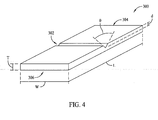
- plated sample 300 may have any suitable dimensions (i.e., length, width, and thickness) that enable testing system 100 to function as described herein. More specifically, the dimensions of plated sample 300 may be based on the material used to fabricate plated sample 300, and/or the predetermined duration used to determine the occurrence of hydrogen embrittlement in plated samples 300. Plated sample 300 has a first end 304, a second end 306, a length L extending therebetween, a width W, and a thickness T. In some implementations, length L is about 8 inch, width W is about 0.5 inch, and thickness T is about 0.03 inch.
- plated sample 300 is not limited to the rectangular shape shown, and may be any suitable shape that enables testing system 100 to function as described herein. Moreover, in the exemplary implementation, plated sample 300 includes a notch 302 positioned at about half of length L of plated sample 300. In the exemplary implementation, notch 302 is defined in the metal substrate before plating, has a depth d defined within a range of about 0.003 inch to about 0.005 inch, and has a notch angle ⁇ of about 60°.
- plated sample 300 is fabricated from a metal substrate (not shown) with plating material deposited thereon.
- plated sample 300 may be fabricated from any suitable material(s) that enables testing system 100 to function as described herein.
- the metal substrate may have any suitable physical properties that enable plated sample 300 to be bent as described herein when subjected to a load.
- An exemplary substrate material includes, but is not limited to, AISI 1095 steel.
- the metal substrate is heat treated to achieve a Rockwell hardness level defined within a range of from about 56 HRC to about 59 HRC by double tempering with a final process temperature of about 450°F.
- the metal substrate may then be plated using any suitable solution that enables testing system 100 to function as described herein.
- Exemplary plating solutions include, but are not limited to, a cadmium solution, a zinc-nickel solution, and the like.
- plating material is deposited onto a surface of the metal substrate at a thickness defined within a range of about 0.0005 inch to about 0.0008 inch.
- Figure 5 illustrates a side view of vise system 106 in a first operational position 402
- Figure 6 illustrates a side view of vise system 106 in a second operational position 404.
- vise system 106 includes a frame 410, a protective cover 412 positioned about frame 410, a first holding member 414 coupled to frame 410, a second holding member 416 coupled to frame 410, and a motor 418 that moves vise system 106 from first operational position 402 to second operational position 404. More specifically, motor 418 is configured to move second holding member 416 substantially linearly along translational axis 420 towards first holding member 414 at a rate of movement.
- motor 418 is configured to move first holding member 414 and second holding member 416 towards each other simultaneously.
- a testing location 415 is defined between first holding member 414 and second holding member 416. Testing location 415 receives sample 300 or 301 when a test of sample 300, 301 is performed using vise system 106.
- Protective cover 412 is configured to block discharge of sample 300 or 301 from testing location 415 during fracture possibly occurring during a test. Further, protective cover 412 is configured to separate a first sample 300, 301 from another sample 300, 301 when a plurality of samples 300, 301 are received within testing location 415.
- testing system 100 is calibrated by moving second holding member 416 into first operational position 402 and loading unplated sample 301 into vise system 106 with notch 302 facing outward from frame 410.
- Unplated sample 301 is positioned between first holding member 414 and second holding member 416 such that first end 304 contacts first holding member 414 and second end 306 contacts second holding member 416.
- second holding member 416 is positioned a distance D from first holding member 414, where distance D is slightly less than length L (shown in Figure 4 ) of unplated sample 301.
- unplated sample 301 has a length of about 8 inch
- second holding member 416 is moved towards first holding member 414 to facilitate reducing distance D to about 7.9 inch.
- unplated sample 301 is bent into a curved (e.g., bow-like) configuration and loaded into vise system 106.
- a distance D (% of FBD) is determined that results in a predetermined percentage of the baseline ultimate failure for a given batch of plated samples 300.
- the predetermined percentage (%OBD) is 75 percent of the baseline ultimate failure distance D for the plated samples 300 used to calibrate testing system 100.
- protective cover 412 is configured to prevent plated samples 300 and/or unplated samples 301 from discharging from vise system 106 during fracture.
- control system 200 (shown in Figure 2 ) is operable to disable the movement of second holding member 416 if protective cover 412 is not positioned about frame 410.
- protective cover 412 activates a switch (not shown) when positioned about frame 410 that enables second holding member 416 to move towards first holding member 414.
- protective cover 412 includes compartments (not shown) associated with each sample 300 and/or 301 to separate them from one another in case of projectiles from fracture striking other samples 300 and/or 301.
- second holding member 416 may be operated to move towards first holding member 414 continuously, iteratively, and/or combinations thereof. Moreover, second holding member 416 may be operated to move towards first holding member 414 at any suitable rate of movement that enables testing system 100 to function as described herein.
- the rate of movement used may facilitate bending unplated sample 301 without fracture until a desired distance D is reached. In some implementations, the rate of movement is from about 0.1 inch per every 3 minutes to about 0.1 inch per minute.
- testing system 100 is ready to determine hydrogen embrittlement in plated samples 300.
- plated samples 300 are fabricated as described above, subjected to a Hydrogen Embrittlement Relief Baking (HERB) process, and loaded into testing system 100 less than about 4 hours after completion of the HERB process.
- HERB Hydrogen Embrittlement Relief Baking
- second holding member 416 is operated to move into first operational position 402. Plated samples 300 are then loaded into vise system 106 as described above for unplated samples 301, and second holding member 416 is moved to second operational position 404 at the rate of movement. After second holding member 416 is in second operational position 404, timing for the predetermined duration begins.
- HERB Hydrogen Embrittlement Relief Baking
- a static load is applied to plated samples 300 at the predetermined percentage of their baseline ultimate failure distance (OBD) based on the calibration. More specifically, second holding member 416 is held at distance D that facilitates applying a static load at 75 percent of the baseline ultimate failure distance for unplated samples 301. Vise system 106 remains in second operational position 404 for the predetermined duration of time, and each plated sample 300 is analyzed after the predetermined duration of time has elapsed.
- OBD baseline ultimate failure distance
- Vise system 106 is sized to receive any suitable number of plated samples 300 that enables testing system 100 to function as described herein.
- each vise system 106 is sized to receive up to three plated samples 300 simultaneously.
- the hydrogen embrittlement determination may be based on how many plated samples 300 fracture before expiration of the predetermined duration. For example, when none of the three plated samples 300 fracture before expiration of the predetermined duration, it may be an indication that hydrogen embrittlement has not occurred and that the plating solution used to fabricate that batch of plated samples 300 is not contaminated and/or embrittling.
- the predetermined duration of time used to determine whether hydrogen embrittlement has occurred is based on a number of factors.
- the predetermined duration of time may be based on the dimensions of plated samples 300, the material used to fabricate plated samples 300, and the predetermined percentage of the baseline ultimate failure distance for plated samples 300 used during operation. In the exemplary implementation, the predetermined duration is about 8 hours.
- Figure 7 is a flow diagram of an exemplary method 500 for determining hydrogen embrittlement in a plated sample.
- the plated sample is positioned 502 between a first holding member and a second holding member.
- the second holding member is moved 504 towards the first holding member to bend the plated sample.
- a static load is then applied 506 to the plated sample for a predetermined duration of time, where the static load is applied by bending the plated sample to a distance that is a predetermined percentage of a baseline ultimate failure distance of the plated sample.
- the testing system and methods described herein facilitate determining the presence of hydrogen embrittlement in plated test samples, which enables a contamination level of an associated plating solution to be determined. More specifically, the plated samples are loaded into the testing system, and a static load is applied to the samples by bending the plated sample to a distance that is a predetermined percentage of a baseline ultimate failure distance of the plated sample.
- the plated samples are fabricated in accordance with the specifications described herein such that a determination of the presence of hydrogen embrittlement may be made in real-time. More specifically, the testing system and methods described herein have been calibrated to enable the determination to be made in about 8 hours. As such, the contamination level of a plating solution may be determined in real-time, which may facilitate an increase in production of plated components.
- a method for determining hydrogen embrittlement in a plated sample comprising: positioning the plated sample between a first holding member and a second holding member; moving the second holding member towards the first holding member to bend the plated sample; and applying a static load to the plated sample for a predetermined duration of time, the static load applied by bending the plated sample to a distance between the first and second holding members that is a predetermined percentage of a baseline ultimate failure distance of the plated sample.
- Clause 2 The method in accordance with Clause 1 further comprising inspecting the plated sample for an indication of fracture, wherein a fracture in the plated sample before expiration of the predetermined duration is used to determine a presence of hydrogen embrittlement.
- Clause 3 The method in accordance with Clause 1, wherein positioning the plated sample between a first holding member and a second holding member comprises bending the plated sample to fit within a distance defined between the first and second holding members that is less than a length of the plated sample.
- Clause 6 The method in accordance with Clause 1, wherein moving the second holding member towards the first holding member comprises selecting the predetermined percentage to be about 75 percent of the baseline ultimate failure distance.
- Clause 7 The method in accordance with Clause 1, wherein applying a static load comprises selecting the predetermined duration based on at least one of dimensions of the plated sample, the predetermined percentage of the baseline ultimate failure distance, and materials used to fabricate the plated sample.
- Clause 8 The method in accordance with Clause 1, wherein applying a static load comprises maintaining the second holding member at a predetermined distance from the first holding member for the predetermined duration.
- Clause 9 The method in accordance with Clause 1 further comprising selecting a plated sample fabricated from an AISI 1095 steel substrate.
- a system for determining hydrogen embrittlement in a plated sample comprising: a frame; a first holding member coupled to said frame; a second holding member coupled to said frame and configured to move relative to said first holding member; and a testing location defined between said first and said second holding members, wherein said testing location receives the plated sample and said second holding member moves towards said first holding member to apply a static load to the plated sample by bending the plated sample to a distance between said first and said second holding members that is a predetermined percentage of a baseline ultimate failure distance of the plated sample.
- Clause 11 The system in accordance with Clause 10 further comprising a control system configured to control a rate of movement of said second holding member towards said first holding member.
- Clause 12 The system in accordance with Clause 10 further comprising a timing device configured to determine a time of failure for the plated sample based on whether the plated sample fractures before expiration of a predetermined duration.
- Clause 13 The system in accordance with Clause 10, wherein said second holding member is slidably coupled to said frame to move towards said first holding member substantially linearly along a translational axis.
- Clause 14 The system in accordance with Clause 10 further comprising a protective cover positioned about said frame that is configured to block discharge of said plated sample from said testing location during fracture.
- Clause 15 The system in accordance with Clause 14, wherein said protective cover is configured to separate the plated sample from another plated sample when a plurality of plated samples are received within said testing location.
- a system for determining hydrogen embrittlement comprising: a frame; a first holding member coupled to said frame; a second holding member coupled to said frame and configured to move towards said first holding member; and a plated sample positioned between said first and said second holding members, wherein said plated sample bends when said second holding member moves towards said first holding member to apply a static load to said plated sample by bending said plated sample to a distance between said first and said second holding members that is a predetermined percentage of a baseline ultimate failure distance of said plated sample.
- Clause 18 The system in accordance with Clause 16, wherein said plated sample is fabricated using at least one of a cadmium solution and a zinc-nickel solution. 19. The system in accordance with Claim 16, wherein said plated sample has a length of about 8 inch, a width of about 0.5 inch, and a thickness of about 0.03 inch.
Landscapes
- Chemical & Material Sciences (AREA)
- Life Sciences & Earth Sciences (AREA)
- Health & Medical Sciences (AREA)
- Immunology (AREA)
- General Health & Medical Sciences (AREA)
- Pathology (AREA)
- General Physics & Mathematics (AREA)
- Physics & Mathematics (AREA)
- Analytical Chemistry (AREA)
- Biochemistry (AREA)
- Engineering & Computer Science (AREA)
- Medicinal Chemistry (AREA)
- Food Science & Technology (AREA)
- Crystallography & Structural Chemistry (AREA)
- Testing Resistance To Weather, Investigating Materials By Mechanical Methods (AREA)
- Investigating Strength Of Materials By Application Of Mechanical Stress (AREA)
- Investigating And Analyzing Materials By Characteristic Methods (AREA)
Abstract
Description
- The field of the present disclosure relates generally to hydrogen embrittlement, and more specifically, to methods and systems for testing for potential hydrogen embrittlement.
- Hydrogen embrittlement refers to a process that causes a metal or metal alloy, such as steel, to become brittle and susceptible to fracture when exposed to a quantity of hydrogen and subjected to a tensile load. As used herein, the term "metal" may refer to a single metal or a metal alloy. Hydrogen embrittlement generally occurs when hydrogen atoms diffuse through the crystalline structure (i.e., matrix) of a metal resulting in an increased pressure within the metal matrix. The increased pressure can adversely affect characteristics of metal such as ductility and tensile strength. At least some known sources of hydrogen atoms are electroplating solutions, pickling solutions, phosphating solutions, paint-stripping solutions, cleaning solutions, and the like.
- In at least some known electrodeposition processes, a metal substrate cathode and a plating material anode are submerged in a plating solution. Electric current is applied to the anode and cathode to deposit a layer of plating material on the surface of the metal substrate via the plating solution. After a desired amount of plating material has been deposited on the metal substrate, the substrate may then be heated to facilitate removing hydrogen trapped in the steel substrate beneath the plating material. Metal substrates also generally have organic surface contaminants, which if not properly cleaned prior to plating, may contaminate the plating solution. As such, prolonged use of the plating solution may affect the quality of the plated sample due to the contaminants. For example, an increased contaminant concentration in the plating solution may decrease the porosity of the plating layer, thereby limiting the amount of hydrogen removed from plated metals during the post-deposition heating process, which is commonly referred to as Hydrogen Embrittlement Relief Baking.
- One known method of determining the porosity level of plating solution involves performing a series of stress tests on samples plated using a plating solution. In one known stress test, plated samples fabricated from a rigid metal substrate, such as AISI 4340 steel, are subjected to tensile stress at 75 percent of their respective ultimate failure load for a predetermined duration. The plating solution is determined to be contaminated if the plated sample breaks before the end of the predetermined duration. However, these known test methods are generally time-consuming, can take up to 200 hours to complete, and thus make it difficult to determine the contamination level of plating solution in real-time.
- In one aspect, a method for use in determining hydrogen embrittlement in a plated sample is provided. The method includes positioning the plated sample between a first holding member and a second holding member, moving the second holding member towards the first holding member to bend the plated sample, and applying a static load to the plated sample for a predetermined duration of time. The static load is applied by bending the plated sample to a distance between the first and second holding members that is a predetermined percentage of a baseline ultimate failure distance of the plated sample.
- In another aspect, a system for use in determining hydrogen embrittlement in a plated sample is provided. The system includes a frame, a first holding member coupled to the frame, a second holding member coupled to the frame and configured to move relative to the first holding member, and a testing location defined between the first and second holding members. Testing location receives the plated sample and the second holding member moves towards the first holding member to apply a static load to the plated sample by bending the plated sample to a distance between the first and second holding members that is a predetermined percentage of a baseline ultimate failure distance of the plated sample.
- In yet another aspect, a system for use in determining hydrogen embrittlement is provided. The system includes a frame, a first holding member coupled to the frame, a second holding member coupled to the frame and configured to move towards the first holding member, a plated sample positioned between the first and second holding members. The plated sample bends when the second holding member moves towards the first holding member to apply a static load to the plated sample by bending the plated sample to a distance between the first and second holding members that is a predetermined percentage of a baseline ultimate failure distance of said plated sample.
-
-
Figure 1 illustrates a perspective view of an exemplary testing system. -
Figure 2 illustrates a front view of the testing system shown inFigure 1 . -
Figure 3 illustrates a schematic diagram of an exemplary control system that may be used with the testing system shown inFigure 1 . -
Figure 4 is a perspective view of an exemplary plated sample that may be used in the testing system shown inFigure 1 . -
Figure 5 illustrates a side view of the vise system shown inFigure 1 in a first operational position. -
Figure 6 illustrates a side view of the vise system shown inFigure 1 in a second operational position. -
Figure 7 is a flow diagram of an exemplary method for determining hydrogen embrittlement in a plated sample that may be used with the testing system shown inFigure 1 . - Implementations of the present disclosure relate to a testing system and methods for determining hydrogen embrittlement in one or more plated metal test samples. The testing system described herein includes a frame, a first holding member coupled to the frame, and a second holding member coupled to the frame that moves towards the first holding member during operation. In the exemplary implementation, plated samples are positioned between the first and second holding members, and the second holding member moves towards the first holding member to apply a static load to the plated samples by bending the plated sample to a distance that is a predetermined percentage of a baseline ultimate failure distance of the plated sample. The plated samples described herein are fabricated from a flexible metal substrate such as AISI 1095 steel, and moving the second holding member towards the first holding member facilitates bending the plated samples in a bow-like configuration. The presence of hydrogen embrittlement is determined if the plated samples fracture before expiration of a predetermined duration. As such, the testing system described herein is configured to provide a determination of hydrogen embrittlement in real-time. As used herein, "real-time" refers to a duration that is less than about 24 hours and, more specifically, less than about 8 hours.
-
Figures 1 and2 illustrate an implementation oftesting system 100. In the exemplary implementation,testing system 100 includes abase 102, awork surface 104 coupled tobase 102, a plurality ofvise systems 106 coupled towork surface 104, and adisplay panel 108 coupled towork surface 104.Display panel 108 andvise systems 106 may be coupled in communication with a control system 200 (not shown inFigure 1 ) that control the operation oftesting system 100. In some implementations, control system 200 may be housed within anelectrical box 110. -
Display panel 108 may be any suitable device that enablestesting system 100 to function as described herein. Exemplarysuitable display panels 108 include, but are not limited to, a liquid crystal display (LCD), an organic light emitting diode (OLED) display, a cathode ray tube (CRT) display, an "electronic ink" display, and the like. In the exemplary implementation,display panel 108 is a touch screen device that enablesdisplay panel 108 to function as an output device and an input device. In alternative implementations,testing system 100 may include one or more input devices separate fromdisplay panel 108 such as, for example, a keyboard, a pointing device, a mouse, a stylus, an audio input device, and the like. -
Figure 3 is a schematic diagram of an exemplary control system 200. As illustrated, control system 200 includes amemory device 202 and aprocessor 204 coupled tomemory device 202 for use in executing operating instructions to be used by testing system 100 (shown inFigure 1 ). In the exemplary implementation,memory device 202 and/orprocessor 204 are programmed to perform one or more operations described herein such as controlling the operation oftesting system 100. For example,processor 204 may be programmed by encoding an operation as one or more executable instructions stored inmemory device 202. -
Processor 204 may include one or more processing units (e.g., in a multicore configuration). As used herein, the term "processor" is not limited to integrated circuits and may include any of a controller, a microcontroller, a microcomputer, a programmable logic controller (PLC), an application specific integrated circuit, and other programmable circuits.Memory device 202 may also include one or more computer readable media such as, without limitation, dynamic random access memory (DRAM), static random access memory (SRAM), a solid state disk, and/or a hard disk. - In the exemplary implementation,
memory device 202 includes one or more devices (not shown) that enable information such as executable instructions and/or other data to be selectively stored and retrieved. In the exemplary implementation, such data may include, but is not limited to, calibration procedures fortesting system 100, testing procedures fortesting system 100, a rate of movement for the second holding member 416 (not shown inFigure 3 ), instructions to activate one or more of the plurality of vise systems 106 (shown inFigure 1 ), and the like. Alternatively, control system 200 may be configured to use any algorithm and/or program that enables the methods and systems to function as described herein. - In some implementations, control system 200 is coupled to a
timing device 206.Timing device 206 monitors plated samples 300 (not shown inFigure 2 ) during operation, and determines if and/or when platedsamples 300 fracture when the static load is applied. As such, the presence of hydrogen embrittlement is determined when the static load is applied to platedsamples 300 and they fracture before expiration of the predetermined duration. - As illustrated in
Figure 4 , platedsample 300 may have any suitable dimensions (i.e., length, width, and thickness) that enabletesting system 100 to function as described herein. More specifically, the dimensions of platedsample 300 may be based on the material used to fabricate platedsample 300, and/or the predetermined duration used to determine the occurrence of hydrogen embrittlement in platedsamples 300. Platedsample 300 has afirst end 304, asecond end 306, a length L extending therebetween, a width W, and a thickness T. In some implementations, length L is about 8 inch, width W is about 0.5 inch, and thickness T is about 0.03 inch. It should also be understood that platedsample 300 is not limited to the rectangular shape shown, and may be any suitable shape that enablestesting system 100 to function as described herein. Moreover, in the exemplary implementation, platedsample 300 includes anotch 302 positioned at about half of length L of platedsample 300. In the exemplary implementation,notch 302 is defined in the metal substrate before plating, has a depth d defined within a range of about 0.003 inch to about 0.005 inch, and has a notch angle θ of about 60°. - In the exemplary implementation, plated
sample 300 is fabricated from a metal substrate (not shown) with plating material deposited thereon. However, platedsample 300 may be fabricated from any suitable material(s) that enablestesting system 100 to function as described herein. The metal substrate may have any suitable physical properties that enable platedsample 300 to be bent as described herein when subjected to a load. An exemplary substrate material includes, but is not limited to, AISI 1095 steel. In some implementations, the metal substrate is heat treated to achieve a Rockwell hardness level defined within a range of from about 56 HRC to about 59 HRC by double tempering with a final process temperature of about 450°F. The metal substrate may then be plated using any suitable solution that enablestesting system 100 to function as described herein. Exemplary plating solutions include, but are not limited to, a cadmium solution, a zinc-nickel solution, and the like. In the exemplary implementation, plating material is deposited onto a surface of the metal substrate at a thickness defined within a range of about 0.0005 inch to about 0.0008 inch. -
Figure 5 illustrates a side view ofvise system 106 in a firstoperational position 402, andFigure 6 illustrates a side view ofvise system 106 in a secondoperational position 404. As illustrated,vise system 106 includes aframe 410, aprotective cover 412 positioned aboutframe 410, a first holdingmember 414 coupled toframe 410, asecond holding member 416 coupled toframe 410, and amotor 418 that movesvise system 106 from firstoperational position 402 to secondoperational position 404. More specifically,motor 418 is configured to move second holdingmember 416 substantially linearly alongtranslational axis 420 towards first holdingmember 414 at a rate of movement. In an alternative implementation,motor 418 is configured to move first holdingmember 414 and second holdingmember 416 towards each other simultaneously. In the exemplary implementation, a testing location 415 is defined between first holdingmember 414 and second holdingmember 416. Testing location 415 receivessample 300 or 301 when a test ofsample 300, 301 is performed usingvise system 106.Protective cover 412 is configured to block discharge ofsample 300 or 301 from testing location 415 during fracture possibly occurring during a test. Further,protective cover 412 is configured to separate afirst sample 300, 301 from anothersample 300, 301 when a plurality ofsamples 300, 301 are received within testing location 415. - In operation, a plurality of unplated samples 301 are fabricated and used to calibrate testing system 100 (shown in
Figure 1 ) to determine a baseline ultimate failure load for platedsamples 300. In the exemplary implementation,testing system 100 is calibrated by moving second holdingmember 416 into firstoperational position 402 and loading unplated sample 301 intovise system 106 withnotch 302 facing outward fromframe 410. Unplated sample 301 is positioned between first holdingmember 414 and second holdingmember 416 such thatfirst end 304 contacts first holdingmember 414 andsecond end 306 contacts second holdingmember 416. In firstoperational position 402, second holdingmember 416 is positioned a distance D from first holdingmember 414, where distance D is slightly less than length L (shown inFigure 4 ) of unplated sample 301. For example, when unplated sample 301 has a length of about 8 inch, second holdingmember 416 is moved towards first holdingmember 414 to facilitate reducing distance D to about 7.9 inch. As such, in the exemplary implementation, unplated sample 301 is bent into a curved (e.g., bow-like) configuration and loaded intovise system 106. - After loading unplated samples 301 into
vise system 106,protective cover 412 may be positioned aboutframe 410, and second holdingmember 416 is operated to move towards first holdingmember 414 at the rate of movement until unplated samples 301 fracture to determine the baseline ultimate failure distance D for platedsamples 300. More specifically, the baseline ultimate failure distance D is determined using the following equation:
Figure 4 ), FBD is the average distance D that fractures unplated samples 301, and OBD is length L minus the average distance D that fractures unplated samples 301. As such, a distance D (% of FBD) is determined that results in a predetermined percentage of the baseline ultimate failure for a given batch of platedsamples 300. In the exemplary implementation, the predetermined percentage (%OBD) is 75 percent of the baseline ultimate failure distance D for the platedsamples 300 used to calibratetesting system 100. - In the exemplary implementation,
protective cover 412 is configured to prevent platedsamples 300 and/or unplated samples 301 from discharging fromvise system 106 during fracture. In some implementations, control system 200 (shown inFigure 2 ) is operable to disable the movement of second holdingmember 416 ifprotective cover 412 is not positioned aboutframe 410. For example, in one implementation,protective cover 412 activates a switch (not shown) when positioned aboutframe 410 that enables second holdingmember 416 to move towards first holdingmember 414. In some implementations,protective cover 412 includes compartments (not shown) associated with eachsample 300 and/or 301 to separate them from one another in case of projectiles from fracture strikingother samples 300 and/or 301. - In some implementations, second holding
member 416 may be operated to move towards first holdingmember 414 continuously, iteratively, and/or combinations thereof. Moreover, second holdingmember 416 may be operated to move towards first holdingmember 414 at any suitable rate of movement that enablestesting system 100 to function as described herein. The rate of movement used may facilitate bending unplated sample 301 without fracture until a desired distance D is reached. In some implementations, the rate of movement is from about 0.1 inch per every 3 minutes to about 0.1 inch per minute. - After testing
system 100 has been calibrated,testing system 100 is ready to determine hydrogen embrittlement in platedsamples 300. In the exemplary implementation, platedsamples 300 are fabricated as described above, subjected to a Hydrogen Embrittlement Relief Baking (HERB) process, and loaded intotesting system 100 less than about 4 hours after completion of the HERB process. For example, second holdingmember 416 is operated to move into firstoperational position 402. Platedsamples 300 are then loaded intovise system 106 as described above for unplated samples 301, and second holdingmember 416 is moved to secondoperational position 404 at the rate of movement. After second holdingmember 416 is in secondoperational position 404, timing for the predetermined duration begins. A static load is applied to platedsamples 300 at the predetermined percentage of their baseline ultimate failure distance (OBD) based on the calibration. More specifically, second holdingmember 416 is held at distance D that facilitates applying a static load at 75 percent of the baseline ultimate failure distance for unplated samples 301.Vise system 106 remains in secondoperational position 404 for the predetermined duration of time, and each platedsample 300 is analyzed after the predetermined duration of time has elapsed. -
Vise system 106 is sized to receive any suitable number of platedsamples 300 that enablestesting system 100 to function as described herein. In the exemplary implementation, eachvise system 106 is sized to receive up to three platedsamples 300 simultaneously. In operation, the hydrogen embrittlement determination may be based on how many platedsamples 300 fracture before expiration of the predetermined duration. For example, when none of the three platedsamples 300 fracture before expiration of the predetermined duration, it may be an indication that hydrogen embrittlement has not occurred and that the plating solution used to fabricate that batch of platedsamples 300 is not contaminated and/or embrittling. In another situation, for example, when only one of the three platedsamples 300 fractures, it may be an indication of inconclusive results and that platedsamples 300 should be re-tested. In yet another situation, for example, when a majority (e.g., two or three) of the threeplates samples 300 fracture, it may be an indication that platedsamples 300 have been impaired by hydrogen embrittlement and that the plating solution is contaminated and/or embrittling. - In some implementations, the predetermined duration of time used to determine whether hydrogen embrittlement has occurred is based on a number of factors. For example, the predetermined duration of time may be based on the dimensions of plated
samples 300, the material used to fabricate platedsamples 300, and the predetermined percentage of the baseline ultimate failure distance for platedsamples 300 used during operation. In the exemplary implementation, the predetermined duration is about 8 hours. -
Figure 7 is a flow diagram of anexemplary method 500 for determining hydrogen embrittlement in a plated sample. In the exemplary implementation, the plated sample is positioned 502 between a first holding member and a second holding member. The second holding member is moved 504 towards the first holding member to bend the plated sample. A static load is then applied 506 to the plated sample for a predetermined duration of time, where the static load is applied by bending the plated sample to a distance that is a predetermined percentage of a baseline ultimate failure distance of the plated sample. - The testing system and methods described herein facilitate determining the presence of hydrogen embrittlement in plated test samples, which enables a contamination level of an associated plating solution to be determined. More specifically, the plated samples are loaded into the testing system, and a static load is applied to the samples by bending the plated sample to a distance that is a predetermined percentage of a baseline ultimate failure distance of the plated sample. The plated samples are fabricated in accordance with the specifications described herein such that a determination of the presence of hydrogen embrittlement may be made in real-time. More specifically, the testing system and methods described herein have been calibrated to enable the determination to be made in about 8 hours. As such, the contamination level of a plating solution may be determined in real-time, which may facilitate an increase in production of plated components.
-
Clause 1. A method for determining hydrogen embrittlement in a plated sample, said method comprising: positioning the plated sample between a first holding member and a second holding member; moving the second holding member towards the first holding member to bend the plated sample; and applying a static load to the plated sample for a predetermined duration of time, the static load applied by bending the plated sample to a distance between the first and second holding members that is a predetermined percentage of a baseline ultimate failure distance of the plated sample. - Clause 2. The method in accordance with
Clause 1 further comprising inspecting the plated sample for an indication of fracture, wherein a fracture in the plated sample before expiration of the predetermined duration is used to determine a presence of hydrogen embrittlement. - Clause 3. The method in accordance with
Clause 1, wherein positioning the plated sample between a first holding member and a second holding member comprises bending the plated sample to fit within a distance defined between the first and second holding members that is less than a length of the plated sample. - Clause 4. The method in accordance with
Clause 1, wherein moving the second holding member towards the first holding member comprises moving the second holding member towards the first holding member substantially linearly along a translational axis. - Clause 5. The method in accordance with
Clause 1, wherein moving the second holding member towards the first holding member comprises moving the second holding member towards the first holding member at a rate of about 0.1 inch per minute. - Clause 6. The method in accordance with
Clause 1, wherein moving the second holding member towards the first holding member comprises selecting the predetermined percentage to be about 75 percent of the baseline ultimate failure distance. - Clause 7. The method in accordance with
Clause 1, wherein applying a static load comprises selecting the predetermined duration based on at least one of dimensions of the plated sample, the predetermined percentage of the baseline ultimate failure distance, and materials used to fabricate the plated sample. - Clause 8. The method in accordance with
Clause 1, wherein applying a static load comprises maintaining the second holding member at a predetermined distance from the first holding member for the predetermined duration. - Clause 9. The method in accordance with
Clause 1 further comprising selecting a plated sample fabricated from an AISI 1095 steel substrate. - Clause 10. A system for determining hydrogen embrittlement in a plated sample, the system comprising: a frame; a first holding member coupled to said frame; a second holding member coupled to said frame and configured to move relative to said first holding member; and a testing location defined between said first and said second holding members, wherein said testing location receives the plated sample and said second holding member moves towards said first holding member to apply a static load to the plated sample by bending the plated sample to a distance between said first and said second holding members that is a predetermined percentage of a baseline ultimate failure distance of the plated sample.
- Clause 11. The system in accordance with Clause 10 further comprising a control system configured to control a rate of movement of said second holding member towards said first holding member.
- Clause 12. The system in accordance with Clause 10 further comprising a timing device configured to determine a time of failure for the plated sample based on whether the plated sample fractures before expiration of a predetermined duration.
- Clause 13. The system in accordance with Clause 10, wherein said second holding member is slidably coupled to said frame to move towards said first holding member substantially linearly along a translational axis.
- Clause 14. The system in accordance with Clause 10 further comprising a protective cover positioned about said frame that is configured to block discharge of said plated sample from said testing location during fracture.
- Clause 15. The system in accordance with Clause 14, wherein said protective cover is configured to separate the plated sample from another plated sample when a plurality of plated samples are received within said testing location.
- Clause 16. A system for determining hydrogen embrittlement, the system comprising: a frame; a first holding member coupled to said frame; a second holding member coupled to said frame and configured to move towards said first holding member; and a plated sample positioned between said first and said second holding members, wherein said plated sample bends when said second holding member moves towards said first holding member to apply a static load to said plated sample by bending said plated sample to a distance between said first and said second holding members that is a predetermined percentage of a baseline ultimate failure distance of said plated sample.
- Clause 17. The system in accordance with Clause 16, wherein said plated sample is fabricated from an AISI 1095 metal substrate.
- Clause 18. The system in accordance with Clause 16, wherein said plated sample is fabricated using at least one of a cadmium solution and a zinc-nickel solution. 19. The system in accordance with Claim 16, wherein said plated sample has a length of about 8 inch, a width of about 0.5 inch, and a thickness of about 0.03 inch.
- Clause 20. The system in accordance with Clause 16, wherein said plated sample comprises a notch defined within a surface thereof.
- This written description uses examples to disclose various implementations, including the best mode, and also to enable any person skilled in the art to practice the various implementations, including making and using any devices or systems and performing any incorporated methods. The patentable scope of the disclosure is defined by the claims, and may include other examples that occur to those skilled in the art. Such other examples are intended to be within the scope of the claims if they have structural elements that do not differ from the literal language of the claims, or if they include equivalent structural elements with insubstantial differences from the literal language of the claims.
Claims (15)
- A method (500) for determining hydrogen embrittlement in a plated sample (300), said method comprising:positioning (502) the plated sample between a first holding member (414) and a second holding member (416);moving (504) the second holding member towards the first holding member to bend the plated sample; andapplying (506) a static load to the plated sample for a predetermined duration of time, the static load applied by bending the plated sample to a distance between the first and second holding members that is a predetermined percentage of a baseline ultimate failure distance of the plated sample.
- The method (500) in accordance with Claim 1 further comprising inspecting the plated sample (300) for an indication of fracture, wherein a fracture in the plated sample before expiration of the predetermined duration is used to determine a presence of hydrogen embrittlement.
- The method (500) in accordance with Claim 1 or 2, wherein positioning (502) the plated sample (300) between a first holding member (414) and a second holding member (416) comprises bending the plated sample to fit within a distance defined between the first and second holding members that is less than a length of the plated sample.
- The method (500) in accordance with any preceding Claim, wherein moving (504) the second holding member (416) towards the first holding member (414) comprises moving the second holding member towards the first holding member substantially linearly along a translational axis (420).
- The method (500) in accordance with any preceding Claim, wherein moving (504) the second holding member (416) towards the first holding member (414) comprises selecting the predetermined percentage to be about 75 percent of the baseline ultimate failure distance.
- The method (500) in accordance with any preceding Claim, wherein applying (506) a static load comprises selecting the predetermined duration based on at least one of dimensions of the plated sample (300), the predetermined percentage of the baseline ultimate failure distance, and materials used to fabricate the plated sample.
- The method (500) in accordance with any preceding Claim, wherein applying (5060) a static load comprises maintaining the second holding member (416) at a predetermined distance from the first holding member (414) for the predetermined duration.
- A system (100) for determining hydrogen embrittlement in a plated sample (300), the system comprising:a frame (410);a first holding member (414) coupled to said frame;a second holding member (416) coupled to said frame and configured to move relative to said first holding member; anda testing location (415) defined between said first and said second holding members, wherein said testing location receives the plated sample and said second holding member moves towards said first holding member to apply a static load to the plated sample by bending the plated sample to a distance between said first and said second holding members that is a predetermined percentage of a baseline ultimate failure distance of the plated sample.
- The system (100) in accordance with Claim 8 further comprising a control system (200) configured to control a rate of movement of said second holding member (416) towards said first holding member (414).
- The system (100) in accordance with Claim 8 or 9 further comprising a timing device (206) configured to determine a time of failure for the plated sample (300) based on whether the plated sample fractures before expiration of a predetermined duration.
- The system (100) in accordance with any of Claims 8-10 further comprising a protective cover (412) positioned about said frame (410) that is configured to block discharge of the plated sample (300) from said testing location (415) during fracture.
- The system (100) in accordance with Claim 11, wherein said protective cover (412) is configured to separate the plated sample (300) from another plated sample when a plurality of plated samples are received within said testing location (415).
- The system (100) in accordance with any of Claims 8-12, wherein the plated sample (300) is fabricated from an AISI 1095 metal substrate.
- The system (100) in accordance with any of Claims 8-13, wherein the plated sample (300) is fabricated using at least one of a cadmium solution and a zinc-nickel solution.
- The system (100) in accordance with any of Claims 8-14, wherein the plated sample (300) comprises a notch (302) defined within a surface thereof.
Applications Claiming Priority (1)
| Application Number | Priority Date | Filing Date | Title |
|---|---|---|---|
| US13/780,944 US9176039B2 (en) | 2013-02-28 | 2013-02-28 | Method and systems for determining hydrogen embrittlement |
Publications (3)
| Publication Number | Publication Date |
|---|---|
| EP2772756A2 true EP2772756A2 (en) | 2014-09-03 |
| EP2772756A3 EP2772756A3 (en) | 2017-12-13 |
| EP2772756B1 EP2772756B1 (en) | 2021-09-15 |
Family
ID=50389776
Family Applications (1)
| Application Number | Title | Priority Date | Filing Date |
|---|---|---|---|
| EP14157099.4A Active EP2772756B1 (en) | 2013-02-28 | 2014-02-27 | Method and systems for determining hydrogen embrittlement |
Country Status (2)
| Country | Link |
|---|---|
| US (1) | US9176039B2 (en) |
| EP (1) | EP2772756B1 (en) |
Cited By (2)
| Publication number | Priority date | Publication date | Assignee | Title |
|---|---|---|---|---|
| CN105067506A (en) * | 2015-08-18 | 2015-11-18 | 无锡乐华自动化科技有限公司 | Automatic wet-heat resistance detecting device based on metal sheets |
| DE102021208667A1 (en) | 2021-08-10 | 2023-02-16 | iChemAnalytics GmbH | Method for determining the resistance of steel to hydrogen embrittlement |
Families Citing this family (16)
| Publication number | Priority date | Publication date | Assignee | Title |
|---|---|---|---|---|
| JP6186658B2 (en) * | 2013-11-29 | 2017-08-30 | 三菱重工業株式会社 | Welded structure design method and welded structure manufacturing method |
| CN104729833B (en) * | 2013-12-18 | 2018-02-13 | 昆山工研院新型平板显示技术中心有限公司 | Flexible screen body crooked test method and system |
| CN104729929B (en) * | 2013-12-18 | 2017-12-05 | 昆山工研院新型平板显示技术中心有限公司 | flexible screen bending method and system |
| DE102014110856B4 (en) * | 2014-07-31 | 2016-04-14 | Schott Ag | Method and device for determining the edge strength of disc-shaped elements made of brittle material |
| JP6128102B2 (en) * | 2014-11-22 | 2017-05-17 | Jfeスチール株式会社 | Method for evaluating delayed fracture characteristics of metal material and metal material |
| CN105092394A (en) * | 2015-08-07 | 2015-11-25 | 中国科学院宁波材料技术与工程研究所 | Bending fracture strain testing device and method |
| JP6544220B2 (en) * | 2015-08-13 | 2019-07-17 | 日本製鉄株式会社 | Hydrogen embrittlement evaluation apparatus and hydrogen embrittlement evaluation method |
| CA3050317C (en) * | 2017-02-17 | 2023-06-20 | Goff Omega Holdings, Llc | Testing method for hydrogen embrittlement |
| US10774439B2 (en) | 2018-11-14 | 2020-09-15 | The Boeing Company | Methods of monitoring a plating bath |
| CN110779820B (en) * | 2019-11-18 | 2022-03-08 | 北京聚睿众邦科技有限公司 | Folding life test machine of folding screen |
| US11235427B2 (en) * | 2020-01-27 | 2022-02-01 | Saudi Arabian Oil Company | Method of testing ERW pipe weld seam for susceptibility to hydrogen embrittlement |
| CN111307612A (en) * | 2020-03-12 | 2020-06-19 | 中国汽车工程研究院股份有限公司 | Method for testing hydrogen-induced delayed fracture performance of ultrahigh-strength automobile steel plate |
| GB202007762D0 (en) * | 2020-05-25 | 2020-07-08 | Lm Wind Power As | Specimen test method |
| CN111982704A (en) * | 2020-07-03 | 2020-11-24 | 中国兵器工业第五九研究所 | Metal material marine climate environment-bending load cooperative acceleration test method |
| US11656169B2 (en) | 2021-03-19 | 2023-05-23 | Saudi Arabian Oil Company | Development of control samples to enhance the accuracy of HIC testing |
| US11788951B2 (en) | 2021-03-19 | 2023-10-17 | Saudi Arabian Oil Company | Testing method to evaluate cold forming effects on carbon steel susceptibility to hydrogen induced cracking (HIC) |
Family Cites Families (19)
| Publication number | Priority date | Publication date | Assignee | Title |
|---|---|---|---|---|
| US3241056A (en) | 1961-03-08 | 1966-03-15 | Jr Samuel C Lawrence | Hydrogen detector probe system and hydrogen detector probe holder |
| US3357903A (en) | 1961-05-12 | 1967-12-12 | Jr Samuel C Lawrence | Monitoring system and method for electroplating steel or other hydrogenpermeable metas |
| US3455152A (en) * | 1967-01-05 | 1969-07-15 | Associated Spring Corp | Method for quickly determining hydrogen embrittlement of metallic parts |
| US3479866A (en) * | 1967-06-19 | 1969-11-25 | Lockheed Aircraft Corp | Hydrogen embrittlement testing method and apparatus |
| US3868849A (en) * | 1973-08-16 | 1975-03-04 | United Artists Music & Records | Ductility tester |
| US4765871A (en) | 1981-12-28 | 1988-08-23 | The Boeing Company | Zinc-nickel electroplated article and method for producing the same |
| JPS58153140A (en) * | 1982-03-08 | 1983-09-12 | Masami Kobayashi | Breaking test apparatus for metal piece |
| US4477778A (en) | 1982-03-15 | 1984-10-16 | Lawrence Electronics Co. | Hydrogen detector |
| EP0230012A3 (en) | 1982-09-30 | 1988-05-04 | The Boeing Company | Method for determining whether a metallic article having a metallic coating thereon will exhibit low hydrogen embrittlement characteristics |
| US4818632A (en) | 1984-11-13 | 1989-04-04 | The Boeing Company | Plated structure exhibiting low hydrogen embrittlement |
| JPS63270492A (en) | 1987-04-28 | 1988-11-08 | Katsukawa Mikaroomu Kogyo Kk | Industrial nickel plating method using insoluble anode |
| US5585570A (en) * | 1994-10-12 | 1996-12-17 | Lra Laboratories, Inc. | Rising step-load test apparatus |
| US6120908A (en) * | 1997-09-08 | 2000-09-19 | Elf Atochem North America, Inc. | Strengthening flat glass by edge coating |
| US7089802B2 (en) | 2003-09-05 | 2006-08-15 | The Boeing Company | Method and apparatus for determining hydrogen embrittlement |
| US6918306B1 (en) * | 2003-09-08 | 2005-07-19 | The United States Of America As Represented By The Secretary Of The Navy | Adjustable flexure loading apparatus for testing long span beams |
| US20060191352A1 (en) * | 2005-02-25 | 2006-08-31 | Lewellen Richard R | Educational device to measure the strength and deflection of a truss |
| US8048285B2 (en) | 2005-05-11 | 2011-11-01 | The Boeing Company | Low hydrogen embrittlement zinc/nickel plating for high strength steels |
| US8177953B2 (en) * | 2008-12-17 | 2012-05-15 | Hamilton Sundstrand Corporation | Method and apparatus for evaluation of coated parts |
| US8513020B2 (en) * | 2009-12-08 | 2013-08-20 | National Oilwell Varco, L.P. | Corrosion testing apparatus and methods |
-
2013
- 2013-02-28 US US13/780,944 patent/US9176039B2/en active Active
-
2014
- 2014-02-27 EP EP14157099.4A patent/EP2772756B1/en active Active
Non-Patent Citations (1)
| Title |
|---|
| None * |
Cited By (3)
| Publication number | Priority date | Publication date | Assignee | Title |
|---|---|---|---|---|
| CN105067506A (en) * | 2015-08-18 | 2015-11-18 | 无锡乐华自动化科技有限公司 | Automatic wet-heat resistance detecting device based on metal sheets |
| CN105067506B (en) * | 2015-08-18 | 2018-07-10 | 北京苏试创博环境可靠性技术有限公司 | A kind of wet-hot aging performance automatic detection device based on sheet metal |
| DE102021208667A1 (en) | 2021-08-10 | 2023-02-16 | iChemAnalytics GmbH | Method for determining the resistance of steel to hydrogen embrittlement |
Also Published As
| Publication number | Publication date |
|---|---|
| US9176039B2 (en) | 2015-11-03 |
| EP2772756A3 (en) | 2017-12-13 |
| US20140238145A1 (en) | 2014-08-28 |
| EP2772756B1 (en) | 2021-09-15 |
Similar Documents
| Publication | Publication Date | Title |
|---|---|---|
| US9176039B2 (en) | Method and systems for determining hydrogen embrittlement | |
| JP4901662B2 (en) | Test piece for evaluating hydrogen embrittlement of thin steel sheet and method for evaluating hydrogen embrittlement of thin steel sheet | |
| Vandebroek et al. | Size effect model for the edge strength of glass with cut and ground edge finishing | |
| CN108398320B (en) | Method for measuring tensile stress corrosion of wrought aluminum alloy | |
| Kale et al. | Oxygen effects on crystal plasticity of Titanium: A multiscale calibration and validation framework | |
| KR20150056556A (en) | Ag-Pd-Cu-Co ALLOY FOR USES IN ELECTRICAL/ELECTRONIC DEVICES | |
| RU2530486C1 (en) | Method of inspecting stress corrosion cracking resistance of pipe steel | |
| Wang et al. | Determination of corrosion type by wavelet-based fractal dimension from electrochemical noise | |
| CN111965205B (en) | Sample preparation method for observing SEM+EBSD of nickel-based powder superalloy in-situ sample micro-area | |
| DE102011014605A1 (en) | Coating method, pile tube and apparatus for carrying out the method | |
| CN113984998B (en) | Method for checking head and tail cutting sufficiency of steel ingot for nuclear power heat transfer tube | |
| CN113609731B (en) | Method for pre-judging magnesium alloy deformation critical cracking under complex stress state | |
| CN102980923A (en) | Internal stress detection method of cold-rolled precise metal thin belt | |
| KR20160124875A (en) | Stress corrosion cracking test method for alcohol environments | |
| Li et al. | Development of liquid-air-interface corrosion of steel in nitrate solutions | |
| CN108254949B (en) | Method for estimating service life and maximum curvature of liquid crystal panel in curved surface state | |
| Kouters et al. | The influence of hydrogen on the fatigue life of metallic leaf spring components in a vacuum environment | |
| JP2008203218A (en) | Method for evaluating delayed fracture resistance of high-strength molten zinc plated steel plate | |
| Laliberte-Riverin et al. | A novel approach for quantifying hydrogen embrittlement using side-grooved CT samples | |
| Mason et al. | Statistics of twin-related domains and the grain boundary network | |
| Ab Razak et al. | Creep-fatigue crack growth behaviour of P91 steels | |
| Moretti et al. | Corrosion-fatigue under rainwater of a Q&T steel: experiments and probabilistic description | |
| JP2016045158A (en) | Pretreatment method for material evaluation | |
| Chen et al. | Determination of forming limit for aluminium alloy sheet eliminating the interferences of through-thickness stress and non-linear strain path | |
| Kang et al. | Development of silver coating process and facilities for ITER thermal shield |
Legal Events
| Date | Code | Title | Description |
|---|---|---|---|
| PUAI | Public reference made under article 153(3) epc to a published international application that has entered the european phase |
Free format text: ORIGINAL CODE: 0009012 |
|
| 17P | Request for examination filed |
Effective date: 20140227 |
|
| AK | Designated contracting states |
Kind code of ref document: A2 Designated state(s): AL AT BE BG CH CY CZ DE DK EE ES FI FR GB GR HR HU IE IS IT LI LT LU LV MC MK MT NL NO PL PT RO RS SE SI SK SM TR |
|
| AX | Request for extension of the european patent |
Extension state: BA ME |
|
| PUAL | Search report despatched |
Free format text: ORIGINAL CODE: 0009013 |
|
| AK | Designated contracting states |
Kind code of ref document: A3 Designated state(s): AL AT BE BG CH CY CZ DE DK EE ES FI FR GB GR HR HU IE IS IT LI LT LU LV MC MK MT NL NO PL PT RO RS SE SI SK SM TR |
|
| AX | Request for extension of the european patent |
Extension state: BA ME |
|
| RIC1 | Information provided on ipc code assigned before grant |
Ipc: G01N 3/20 20060101ALI20171106BHEP Ipc: G01N 33/20 20060101AFI20171106BHEP |
|
| STAA | Information on the status of an ep patent application or granted ep patent |
Free format text: STATUS: REQUEST FOR EXAMINATION WAS MADE |
|
| R17P | Request for examination filed (corrected) |
Effective date: 20180611 |
|
| RBV | Designated contracting states (corrected) |
Designated state(s): AL AT BE BG CH CY CZ DE DK EE ES FI FR GB GR HR HU IE IS IT LI LT LU LV MC MK MT NL NO PL PT RO RS SE SI SK SM TR |
|
| STAA | Information on the status of an ep patent application or granted ep patent |
Free format text: STATUS: EXAMINATION IS IN PROGRESS |
|
| 17Q | First examination report despatched |
Effective date: 20181204 |
|
| REG | Reference to a national code |
Ref country code: DE Ref legal event code: R079 Ref document number: 602014080093 Country of ref document: DE Free format text: PREVIOUS MAIN CLASS: G01N0033200000 Ipc: G01N0033204000 |
|
| GRAP | Despatch of communication of intention to grant a patent |
Free format text: ORIGINAL CODE: EPIDOSNIGR1 |
|
| STAA | Information on the status of an ep patent application or granted ep patent |
Free format text: STATUS: GRANT OF PATENT IS INTENDED |
|
| RIC1 | Information provided on ipc code assigned before grant |
Ipc: G01N 3/20 20060101ALI20210325BHEP Ipc: G01N 33/204 20190101AFI20210325BHEP |
|
| INTG | Intention to grant announced |
Effective date: 20210416 |
|
| GRAS | Grant fee paid |
Free format text: ORIGINAL CODE: EPIDOSNIGR3 |
|
| GRAA | (expected) grant |
Free format text: ORIGINAL CODE: 0009210 |
|
| STAA | Information on the status of an ep patent application or granted ep patent |
Free format text: STATUS: THE PATENT HAS BEEN GRANTED |
|
| AK | Designated contracting states |
Kind code of ref document: B1 Designated state(s): AL AT BE BG CH CY CZ DE DK EE ES FI FR GB GR HR HU IE IS IT LI LT LU LV MC MK MT NL NO PL PT RO RS SE SI SK SM TR |
|
| REG | Reference to a national code |
Ref country code: CH Ref legal event code: EP Ref country code: GB Ref legal event code: FG4D |
|
| REG | Reference to a national code |
Ref country code: DE Ref legal event code: R096 Ref document number: 602014080093 Country of ref document: DE |
|
| REG | Reference to a national code |
Ref country code: IE Ref legal event code: FG4D |
|
| REG | Reference to a national code |
Ref country code: AT Ref legal event code: REF Ref document number: 1430880 Country of ref document: AT Kind code of ref document: T Effective date: 20211015 |
|
| REG | Reference to a national code |
Ref country code: LT Ref legal event code: MG9D |
|
| REG | Reference to a national code |
Ref country code: NL Ref legal event code: MP Effective date: 20210915 |
|
| PG25 | Lapsed in a contracting state [announced via postgrant information from national office to epo] |
Ref country code: NO Free format text: LAPSE BECAUSE OF FAILURE TO SUBMIT A TRANSLATION OF THE DESCRIPTION OR TO PAY THE FEE WITHIN THE PRESCRIBED TIME-LIMIT Effective date: 20211215 Ref country code: FI Free format text: LAPSE BECAUSE OF FAILURE TO SUBMIT A TRANSLATION OF THE DESCRIPTION OR TO PAY THE FEE WITHIN THE PRESCRIBED TIME-LIMIT Effective date: 20210915 Ref country code: BG Free format text: LAPSE BECAUSE OF FAILURE TO SUBMIT A TRANSLATION OF THE DESCRIPTION OR TO PAY THE FEE WITHIN THE PRESCRIBED TIME-LIMIT Effective date: 20211215 Ref country code: LT Free format text: LAPSE BECAUSE OF FAILURE TO SUBMIT A TRANSLATION OF THE DESCRIPTION OR TO PAY THE FEE WITHIN THE PRESCRIBED TIME-LIMIT Effective date: 20210915 Ref country code: RS Free format text: LAPSE BECAUSE OF FAILURE TO SUBMIT A TRANSLATION OF THE DESCRIPTION OR TO PAY THE FEE WITHIN THE PRESCRIBED TIME-LIMIT Effective date: 20210915 Ref country code: SE Free format text: LAPSE BECAUSE OF FAILURE TO SUBMIT A TRANSLATION OF THE DESCRIPTION OR TO PAY THE FEE WITHIN THE PRESCRIBED TIME-LIMIT Effective date: 20210915 Ref country code: HR Free format text: LAPSE BECAUSE OF FAILURE TO SUBMIT A TRANSLATION OF THE DESCRIPTION OR TO PAY THE FEE WITHIN THE PRESCRIBED TIME-LIMIT Effective date: 20210915 |
|
| REG | Reference to a national code |
Ref country code: AT Ref legal event code: MK05 Ref document number: 1430880 Country of ref document: AT Kind code of ref document: T Effective date: 20210915 |
|
| PG25 | Lapsed in a contracting state [announced via postgrant information from national office to epo] |
Ref country code: LV Free format text: LAPSE BECAUSE OF FAILURE TO SUBMIT A TRANSLATION OF THE DESCRIPTION OR TO PAY THE FEE WITHIN THE PRESCRIBED TIME-LIMIT Effective date: 20210915 Ref country code: GR Free format text: LAPSE BECAUSE OF FAILURE TO SUBMIT A TRANSLATION OF THE DESCRIPTION OR TO PAY THE FEE WITHIN THE PRESCRIBED TIME-LIMIT Effective date: 20211216 |
|
| PG25 | Lapsed in a contracting state [announced via postgrant information from national office to epo] |
Ref country code: AT Free format text: LAPSE BECAUSE OF FAILURE TO SUBMIT A TRANSLATION OF THE DESCRIPTION OR TO PAY THE FEE WITHIN THE PRESCRIBED TIME-LIMIT Effective date: 20210915 |
|
| PG25 | Lapsed in a contracting state [announced via postgrant information from national office to epo] |
Ref country code: IS Free format text: LAPSE BECAUSE OF FAILURE TO SUBMIT A TRANSLATION OF THE DESCRIPTION OR TO PAY THE FEE WITHIN THE PRESCRIBED TIME-LIMIT Effective date: 20220115 Ref country code: SM Free format text: LAPSE BECAUSE OF FAILURE TO SUBMIT A TRANSLATION OF THE DESCRIPTION OR TO PAY THE FEE WITHIN THE PRESCRIBED TIME-LIMIT Effective date: 20210915 Ref country code: SK Free format text: LAPSE BECAUSE OF FAILURE TO SUBMIT A TRANSLATION OF THE DESCRIPTION OR TO PAY THE FEE WITHIN THE PRESCRIBED TIME-LIMIT Effective date: 20210915 Ref country code: RO Free format text: LAPSE BECAUSE OF FAILURE TO SUBMIT A TRANSLATION OF THE DESCRIPTION OR TO PAY THE FEE WITHIN THE PRESCRIBED TIME-LIMIT Effective date: 20210915 Ref country code: PT Free format text: LAPSE BECAUSE OF FAILURE TO SUBMIT A TRANSLATION OF THE DESCRIPTION OR TO PAY THE FEE WITHIN THE PRESCRIBED TIME-LIMIT Effective date: 20220117 Ref country code: PL Free format text: LAPSE BECAUSE OF FAILURE TO SUBMIT A TRANSLATION OF THE DESCRIPTION OR TO PAY THE FEE WITHIN THE PRESCRIBED TIME-LIMIT Effective date: 20210915 Ref country code: NL Free format text: LAPSE BECAUSE OF FAILURE TO SUBMIT A TRANSLATION OF THE DESCRIPTION OR TO PAY THE FEE WITHIN THE PRESCRIBED TIME-LIMIT Effective date: 20210915 Ref country code: ES Free format text: LAPSE BECAUSE OF FAILURE TO SUBMIT A TRANSLATION OF THE DESCRIPTION OR TO PAY THE FEE WITHIN THE PRESCRIBED TIME-LIMIT Effective date: 20210915 Ref country code: EE Free format text: LAPSE BECAUSE OF FAILURE TO SUBMIT A TRANSLATION OF THE DESCRIPTION OR TO PAY THE FEE WITHIN THE PRESCRIBED TIME-LIMIT Effective date: 20210915 Ref country code: CZ Free format text: LAPSE BECAUSE OF FAILURE TO SUBMIT A TRANSLATION OF THE DESCRIPTION OR TO PAY THE FEE WITHIN THE PRESCRIBED TIME-LIMIT Effective date: 20210915 Ref country code: AL Free format text: LAPSE BECAUSE OF FAILURE TO SUBMIT A TRANSLATION OF THE DESCRIPTION OR TO PAY THE FEE WITHIN THE PRESCRIBED TIME-LIMIT Effective date: 20210915 |
|
| REG | Reference to a national code |
Ref country code: DE Ref legal event code: R097 Ref document number: 602014080093 Country of ref document: DE |
|
| PLBE | No opposition filed within time limit |
Free format text: ORIGINAL CODE: 0009261 |
|
| STAA | Information on the status of an ep patent application or granted ep patent |
Free format text: STATUS: NO OPPOSITION FILED WITHIN TIME LIMIT |
|
| PG25 | Lapsed in a contracting state [announced via postgrant information from national office to epo] |
Ref country code: DK Free format text: LAPSE BECAUSE OF FAILURE TO SUBMIT A TRANSLATION OF THE DESCRIPTION OR TO PAY THE FEE WITHIN THE PRESCRIBED TIME-LIMIT Effective date: 20210915 |
|
| 26N | No opposition filed |
Effective date: 20220616 |
|
| PG25 | Lapsed in a contracting state [announced via postgrant information from national office to epo] |
Ref country code: SI Free format text: LAPSE BECAUSE OF FAILURE TO SUBMIT A TRANSLATION OF THE DESCRIPTION OR TO PAY THE FEE WITHIN THE PRESCRIBED TIME-LIMIT Effective date: 20210915 |
|
| PG25 | Lapsed in a contracting state [announced via postgrant information from national office to epo] |
Ref country code: MC Free format text: LAPSE BECAUSE OF FAILURE TO SUBMIT A TRANSLATION OF THE DESCRIPTION OR TO PAY THE FEE WITHIN THE PRESCRIBED TIME-LIMIT Effective date: 20210915 |
|
| REG | Reference to a national code |
Ref country code: CH Ref legal event code: PL |
|
| REG | Reference to a national code |
Ref country code: BE Ref legal event code: MM Effective date: 20220228 |
|
| PG25 | Lapsed in a contracting state [announced via postgrant information from national office to epo] |
Ref country code: LU Free format text: LAPSE BECAUSE OF NON-PAYMENT OF DUE FEES Effective date: 20220227 |
|
| PG25 | Lapsed in a contracting state [announced via postgrant information from national office to epo] |
Ref country code: LI Free format text: LAPSE BECAUSE OF NON-PAYMENT OF DUE FEES Effective date: 20220228 Ref country code: IT Free format text: LAPSE BECAUSE OF FAILURE TO SUBMIT A TRANSLATION OF THE DESCRIPTION OR TO PAY THE FEE WITHIN THE PRESCRIBED TIME-LIMIT Effective date: 20210915 Ref country code: IE Free format text: LAPSE BECAUSE OF NON-PAYMENT OF DUE FEES Effective date: 20220227 Ref country code: CH Free format text: LAPSE BECAUSE OF NON-PAYMENT OF DUE FEES Effective date: 20220228 |
|
| PG25 | Lapsed in a contracting state [announced via postgrant information from national office to epo] |
Ref country code: BE Free format text: LAPSE BECAUSE OF NON-PAYMENT OF DUE FEES Effective date: 20220228 |
|
| P01 | Opt-out of the competence of the unified patent court (upc) registered |
Effective date: 20230516 |
|
| PG25 | Lapsed in a contracting state [announced via postgrant information from national office to epo] |
Ref country code: HU Free format text: LAPSE BECAUSE OF FAILURE TO SUBMIT A TRANSLATION OF THE DESCRIPTION OR TO PAY THE FEE WITHIN THE PRESCRIBED TIME-LIMIT; INVALID AB INITIO Effective date: 20140227 |
|
| PG25 | Lapsed in a contracting state [announced via postgrant information from national office to epo] |
Ref country code: MK Free format text: LAPSE BECAUSE OF FAILURE TO SUBMIT A TRANSLATION OF THE DESCRIPTION OR TO PAY THE FEE WITHIN THE PRESCRIBED TIME-LIMIT Effective date: 20210915 Ref country code: CY Free format text: LAPSE BECAUSE OF FAILURE TO SUBMIT A TRANSLATION OF THE DESCRIPTION OR TO PAY THE FEE WITHIN THE PRESCRIBED TIME-LIMIT Effective date: 20210915 |
|
| PG25 | Lapsed in a contracting state [announced via postgrant information from national office to epo] |
Ref country code: MT Free format text: LAPSE BECAUSE OF FAILURE TO SUBMIT A TRANSLATION OF THE DESCRIPTION OR TO PAY THE FEE WITHIN THE PRESCRIBED TIME-LIMIT Effective date: 20210915 |
|
| PG25 | Lapsed in a contracting state [announced via postgrant information from national office to epo] |
Ref country code: TR Free format text: LAPSE BECAUSE OF FAILURE TO SUBMIT A TRANSLATION OF THE DESCRIPTION OR TO PAY THE FEE WITHIN THE PRESCRIBED TIME-LIMIT Effective date: 20210915 |
|
| PGFP | Annual fee paid to national office [announced via postgrant information from national office to epo] |
Ref country code: GB Payment date: 20260227 Year of fee payment: 13 |
|
| PGFP | Annual fee paid to national office [announced via postgrant information from national office to epo] |
Ref country code: DE Payment date: 20260227 Year of fee payment: 13 |
|
| PGFP | Annual fee paid to national office [announced via postgrant information from national office to epo] |
Ref country code: FR Payment date: 20260225 Year of fee payment: 13 |