EP2772669A1 - Sealing device, and suspension device provided with said sealing device - Google Patents
Sealing device, and suspension device provided with said sealing device Download PDFInfo
- Publication number
- EP2772669A1 EP2772669A1 EP12844258.9A EP12844258A EP2772669A1 EP 2772669 A1 EP2772669 A1 EP 2772669A1 EP 12844258 A EP12844258 A EP 12844258A EP 2772669 A1 EP2772669 A1 EP 2772669A1
- Authority
- EP
- European Patent Office
- Prior art keywords
- scraper
- tube
- peripheral surface
- dust seal
- sealing device
- Prior art date
- Legal status (The legal status is an assumption and is not a legal conclusion. Google has not performed a legal analysis and makes no representation as to the accuracy of the status listed.)
- Granted
Links
Images
Classifications
-
- F—MECHANICAL ENGINEERING; LIGHTING; HEATING; WEAPONS; BLASTING
- F16—ENGINEERING ELEMENTS AND UNITS; GENERAL MEASURES FOR PRODUCING AND MAINTAINING EFFECTIVE FUNCTIONING OF MACHINES OR INSTALLATIONS; THERMAL INSULATION IN GENERAL
- F16F—SPRINGS; SHOCK-ABSORBERS; MEANS FOR DAMPING VIBRATION
- F16F9/00—Springs, vibration-dampers, shock-absorbers, or similarly-constructed movement-dampers using a fluid or the equivalent as damping medium
- F16F9/32—Details
- F16F9/36—Special sealings, including sealings or guides for piston-rods
- F16F9/369—Sealings for elements other than pistons or piston rods, e.g. valves
-
- F—MECHANICAL ENGINEERING; LIGHTING; HEATING; WEAPONS; BLASTING
- F16—ENGINEERING ELEMENTS AND UNITS; GENERAL MEASURES FOR PRODUCING AND MAINTAINING EFFECTIVE FUNCTIONING OF MACHINES OR INSTALLATIONS; THERMAL INSULATION IN GENERAL
- F16F—SPRINGS; SHOCK-ABSORBERS; MEANS FOR DAMPING VIBRATION
- F16F9/00—Springs, vibration-dampers, shock-absorbers, or similarly-constructed movement-dampers using a fluid or the equivalent as damping medium
- F16F9/32—Details
- F16F9/36—Special sealings, including sealings or guides for piston-rods
-
- F—MECHANICAL ENGINEERING; LIGHTING; HEATING; WEAPONS; BLASTING
- F16—ENGINEERING ELEMENTS AND UNITS; GENERAL MEASURES FOR PRODUCING AND MAINTAINING EFFECTIVE FUNCTIONING OF MACHINES OR INSTALLATIONS; THERMAL INSULATION IN GENERAL
- F16J—PISTONS; CYLINDERS; SEALINGS
- F16J15/00—Sealings
- F16J15/16—Sealings between relatively-moving surfaces
- F16J15/32—Sealings between relatively-moving surfaces with elastic sealings, e.g. O-rings
- F16J15/3204—Sealings between relatively-moving surfaces with elastic sealings, e.g. O-rings with at least one lip
-
- F—MECHANICAL ENGINEERING; LIGHTING; HEATING; WEAPONS; BLASTING
- F16—ENGINEERING ELEMENTS AND UNITS; GENERAL MEASURES FOR PRODUCING AND MAINTAINING EFFECTIVE FUNCTIONING OF MACHINES OR INSTALLATIONS; THERMAL INSULATION IN GENERAL
- F16J—PISTONS; CYLINDERS; SEALINGS
- F16J15/00—Sealings
- F16J15/16—Sealings between relatively-moving surfaces
- F16J15/32—Sealings between relatively-moving surfaces with elastic sealings, e.g. O-rings
- F16J15/3204—Sealings between relatively-moving surfaces with elastic sealings, e.g. O-rings with at least one lip
- F16J15/3232—Sealings between relatively-moving surfaces with elastic sealings, e.g. O-rings with at least one lip having two or more lips
-
- F—MECHANICAL ENGINEERING; LIGHTING; HEATING; WEAPONS; BLASTING
- F16—ENGINEERING ELEMENTS AND UNITS; GENERAL MEASURES FOR PRODUCING AND MAINTAINING EFFECTIVE FUNCTIONING OF MACHINES OR INSTALLATIONS; THERMAL INSULATION IN GENERAL
- F16F—SPRINGS; SHOCK-ABSORBERS; MEANS FOR DAMPING VIBRATION
- F16F2224/00—Materials; Material properties
- F16F2224/02—Materials; Material properties solids
- F16F2224/0291—PTFE
-
- F—MECHANICAL ENGINEERING; LIGHTING; HEATING; WEAPONS; BLASTING
- F16—ENGINEERING ELEMENTS AND UNITS; GENERAL MEASURES FOR PRODUCING AND MAINTAINING EFFECTIVE FUNCTIONING OF MACHINES OR INSTALLATIONS; THERMAL INSULATION IN GENERAL
- F16F—SPRINGS; SHOCK-ABSORBERS; MEANS FOR DAMPING VIBRATION
- F16F2230/00—Purpose; Design features
- F16F2230/30—Sealing arrangements
Definitions
- the present invention relates to a sealing device and a suspension device with the sealing device.
- a sealing device is used in a shock absorber for suppressing vibration of transportation equipment or a building, a suspension device containing this shock absorber or the like and seals working fluid stored in the shock absorber or the suspension device.
- a suspension device called a front fork for suspending a front wheel is installed in a saddled vehicle such as a motorcycle.
- the suspension device includes a suspension main body with an outer tube and an inner tube inserted in such a manner as to project from and retract into the outer tube, and the shock absorber is housed in this suspension main body.
- a reservoir for temperature compensation and volume compensation is formed between the suspension main body and the shock absorber and stores working fluid and gas.
- a sealing device used in the suspension device prevents the leakage of the working fluid and the gas in the reservoir from the suspension main body to an outer side (atmosphere side).
- JP04-32342A discloses a sealing device including an annular dust seal held on an opening end part of an outer tube and held in sliding contact with the outer peripheral surface of an inner tube, and an annular oil seal held on the opening end part of the outer tube, held in sliding contact with the outer peripheral surface of the inner tube and arranged at an inner side
- This sealing device scrapes off foreign substances adhering to the outer peripheral surface of the inner tube by the dust seal and scrapes off the working fluid adhering to the outer peripheral surface of the inner tube by the oil seal.
- the sealing device can prevent the leakage of the working fluid and the gas in the suspension main body to the outer side (atmosphere side) due to scratches on sliding surfaces of the oil seal and the inner tube caused by foreign substances and maintain the interior of the suspension main body in a sealed state.
- the present invention aims to provide a sealing device capable of scraping off foreign substances adhering to the outer peripheral surface of an axial member even under a severe use environment and a suspension device with this sealing device.
- a sealing device adapted to seal between a tube member and an axial member movably inserted into the tube member.
- the sealing device includes a dust seal held on an opening end part of the tube member and including an annular dust seal lip held in sliding contact with the outer peripheral surface of the axial member; and a scraper arranged at an inner side of the dust seal and including an annular lip portion slidably pressed into contact with the outer peripheral surface of the axial member, wherein the hardness of the lip portion is set to be higher than that of the dust seal lip.
- a sealing device seals between an outer tube 1 as a tube member and an inner tube 2 as an axial member movably inserted into the outer tube 1.
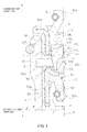
- the sealing device includes a dust seal 3 held on an opening end part of the outer tube 1 and including an annular dust seal lip 31 held in sliding contact with the outer peripheral surface of the inner tube 2, and a scraper 4 arranged at an inner side (lower side in FIG. 1 ) of the dust seal 3 and including an annular lip portion 41 slidably pressed into contact with the outer peripheral surface of the inner tube 2. Further, the hardness of the lip portion 41 is set to be higher than that of the dust seal lip 31. It should be noted that FIGS. 1 and 2 show a sealing device in a free state not held in contact with the inner tube 2 and the outer peripheral surface of the inner tube 2 is shown by imaginary line.
- the sealing device is used in a suspension device called a front fork for suspending a front wheel in a saddled vehicle such as a motorcycle.
- a basic configuration of the front fork is not shown in detail since being well-known.
- the front fork includes a telescopic suspension main body F including the outer tube 1 and the inner tube 2 inserted in such a manner as to project from and retract into the outer tube 1, and an unillustrated shock absorber housed in the suspension main body F for suppressing extension and contraction movements of the suspension main body F.
- An unillustrated reservoir is formed between the interior of the suspension main body F and the shock absorber.
- the reservoir performs temperature compensation and volume compensation of the shock absorber by storing working fluid and gas.
- the working fluid is liquid such as water, glycol solution or oil and the gas is inert gas such as nitrogen. It should be noted that the configuration of the shock absorber is not described in detail since any known configuration may be adopted.
- One opening of the suspension main body F located on an upper side in FIG. 1 is closed by an unillustrated cap member.
- the other opening of the suspension main body F located on a lower side in FIG. 1 is closed by an unillustrated bottom member.
- a tubular clearance T formed in a part where the outer tube 1 and the inner tube 2 overlap in an axial direction is closed by the sealing device. This can prevent the leakage of the working fluid in the reservoir from the suspension main body F to an outer side (atmosphere side).
- the sealing device further includes the dust seal 3 held on the opening end part of the outer tube 1 as the tube member, and an oil seal 5 held on the opening end part of the outer tube 1 and arranged in series at an inner side (working-fluid side) below the dust seal 3 in FIG. 1 .
- the dust seal 3 and the oil seal 5 are arranged with a predetermined clearance, and a space A is formed between the dust seal 3 and the oil seal 5.
- An annular groove 10 having a U-shaped cross-section is formed between the dust seal 3 and the oil seal 5 on the inner peripheral surface of the opening end part of the outer tube 1.
- the dust seal 3 is formed by covering an insert metal 30a made of metal with NBR (nitrile rubber).
- NBR nitrile rubber
- a part including the insert metal 30a inside is a dust seal main body 30, and is annularly formed and fitted into the outer tube 1.
- the dust seal lip 31 is continuously connected to the inner periphery of an outer side (atmosphere side) of this dust seal main body 30 located on the upper side in FIG. 1 .
- An inner peripheral end 31a which is a part of the dust seal lip 31 having a smallest diameter, is formed to have a diameter smaller than an outer diameter of the inner tube 2. Further, a garter spring 6 for pressing the inner peripheral end 31a of the dust seal lip 31 against the inner tube 2 is provided on the outer periphery of the dust seal lip 31.
- the inner side (working-fluid side) of the dust seal main body 30 located on the lower side in FIG. 1 is formed to project downward from a base portion 31b of the dust seal lip 31 continuously connected to the dust seal main body 30. That is, an inner side surface 31c of the base portion 31b and an inner peripheral surface 30b on the inner side of the dust seal main body 30 are arranged to form an inverted L-shaped cross-section.
- the oil seal 5 is formed by covering an insert metal 50a made of metal with NBR.
- the annular oil seal lip 51 made of this NBR scrapes off the working fluid adhering to the outer peripheral surface of the inner tube 2.
- oil seal main body 50 a part including the insert metal 50a inside is an oil seal main body 50, and is annularly formed and fitted into the outer tube 1.
- the oil seal lip 51 is continuously connected to the inner periphery of an outer side (atmosphere side) of this oil seal main body 50 located on the upper side in FIG. 1 .
- the oil seal lip 51 is forked into upper and lower sides (atmosphere side and working-fluid side) in FIG. 1 and includes a sub lip 52 arranged on an outer side (atmosphere side) located on the upper side in FIG. 1 and a main lip 53 arranged on an inner side (working-fluid side) located on the lower side in FIG. 1 .
- the oil seal 5 scrapes off the working fluid adhering to the outer peripheral surface of the inner tube 2 by the main lip 53 and scrapes off foreign substances adhering to the outer peripheral surface of the inner tube 2 by the sub lip 52.
- An inner peripheral end 52a which is a part of the sub lip 52 having a smallest diameter, is formed to have a diameter smaller than the outer diameter of the inner tube 2.
- An inner peripheral end 53a which is a part of the main lip 53 having a smallest diameter, is formed to have a diameter smaller than the outer diameter of the inner tube 2.
- a garter spring 7 for pressing the inner peripheral end 53a of the main lip 53 against the inner tube 2 is provided on the outer periphery of the main lip 53.
- annular groove 5a is formed on an outer side surface 50b of the oil seal main body 50 on the oil seal lip 51 side.
- the sealing device further includes the annular scraper 4 arranged in series between the dust seal 3 and the oil seal 5.
- the scraper 4 is made of PTFE (polytetrafluoroethylene) having a higher hardness than the NBR forming the dust seal lip 31.
- the scraper 4 includes an annular scraper main body 40, and an annular lip portion 41 continuously connected to the inner periphery of the scraper main body 40 and inclined toward the outer side (atmosphere side) located on the upper side in FIG. 1 .
- an inner peripheral end 41a of the lip portion 41 has a smallest diameter and is slightly smaller than the outer diameter of the inner tube 2.
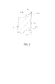
- an outer side surface 41b and an inner peripheral surface 41c intersect at an acute angle on the inner peripheral end 41a as an apex. Further, as shown in FIG. 2 , an angle a formed between the outer side surface 41b of the lip portion 41 and the outer peripheral surface of the inner tube 2 is set to be larger than an angle b formed between the inner peripheral surface 41c of the lip portion 41 and the outer peripheral surface of the inner tube 2.
- a stopper 40b projecting toward the inner side (working-fluid side) located on the lower side in FIG. 1 is formed with the scraper main body 40.
- the tip of the stopper 40b can come into contact with the groove 5a of the oil seal 5 and the stopper 40b is so arranged as not to interfere with the sub lip 52.
- An outer diameter of the scraper main body 40 is smaller than an inner diameter of the dust seal main body 30. This enables the scraper 4 to move in the axial direction (vertical direction in FIG. 1 ), following the inner tube 2, from a position where an outer side surface 40c of the scraper main body 40 located on the upper side in FIG. 1 is in contact with the inner side surface 31c of the base portion 31b of the dust seal lip 31 to a position where the tip of the stopper 40b in the scraper main body 40 is in contact with the groove 5a of the oil seal 5.
- a tubular clearance L is formed between the outer periphery of the scraper 4, i.e. the outer peripheral surface (not denoted by a reference sign) of the scarper main body 40 and the inner peripheral surface 30b of the dust seal main body 30. This enables the scraper 4 to move also in a radial direction (lateral direction in FIG. 1 ), following the inner tube 2. It should be noted that the clearance L communicates with the space A formed between the oil seal 5 and the dust seal 3.
- the sealing device includes the dust seal 3 and the scraper 4 arranged at the inner side (working-fluid side) of the dust seal 3. Since the hardness of the lip portion 41 of the scraper 4 is set to be higher than that of the dust seal lip 31, foreign substances that cannot be scraped off by the dust seal lip 31 can be scraped off by the scraper 4.
- the sealing device can reliably scrape off foreign substances adhering to the outer peripheral surface of the inner tube 2 as the axial member.
- the scraper 4 is arranged at the outer side (atmosphere side) of the dust seal 3, there is a possibility that the scraper 4 is scratched by foreign substances having a large particle diameter.
- the scraper 4 is arranged at the inner side (working-fluid side) of the dust seal 3 in the present embodiment, foreign substances having a large particle diameter can be scraped off by the dust seal 3 and the damage of the scraper 4 can be prevented.
- the scraper 4 can move following the inner tube 2, maintain a contact state between the inner tube 2 and the scraper 4, and prevent an occurrence of a gap between the inner tube 2 and the scraper 4.
- the scraper 4 since being able to move between the dust seal 3 and the oil seal 5, the scraper 4 moves together with the inner tube 2 until coming into contact with the oil seal 5 when the front fork is compressed. When coming into contact with the oil seal 5, the scraper 4 scrapes off foreign substances adhering to the outer peripheral surface of the inner tube 2 while being supported on the oil seal 5. At this time, since the scraper 4 is distant from the dust seal 3, the foreign substances scraped off by the scraper 4 can be moved to the space A via the clearance L.
- the annular groove 10 is formed between the dust seal 3 and the oil seal 5 on the inner peripheral surface of the opening end part of the outer tube 1, the volume of the space A can be enlarged and more foreign substances can be stored.
- stopper 40b is formed with the scraper main body 40 and the stopper 40b can come into contact with the groove 5a of the oil seal 5, the interference of the scraper 4 with the oil seal lip 51 can be avoided.
- outer side surface 41b and the inner peripheral surface 41c of the lip portion 41 in the scraper 4 intersect at an acute angle and the angle a formed between the outer side surface 41b and the outer peripheral surface of the inner tube 2 is set to be larger than the angle b formed between the inner peripheral surface 41c and the outer peripheral surface of the inner tube 2, foreign substances adhering to the outer peripheral surface of the inner tube 2 can be more reliably scraped off.
- the scraper 4 is made of PTFE, a frictional force acting between the scraper 4 and the inner tube 2 can be reduced.
- sealing device is described to be used in the front fork for motorcycle in the above embodiment, the above sealing device may be used in another suspension device, a shock absorber or the like.
- sealing device is illustrated to have a structure for closing the tubular clearance T formed in an overlapping part of the outer tube 1 as the tube member and the inner tube 2 as the axial member in the above embodiment, there is no limitation to this.
- the sealing device may be structured to close between a cylinder as a tube member and a piston rod as an axial member inserted into the cylinder.
- the scraper 4 which is arranged between the dust seal 3 and the oil seal 5 is movable following the inner tube (axial member) 2 in the above embodiment, the scraper 4 may be fixed to the outer tube (tubular member) 1 side. In this case, it is not necessary to form the groove 5a on the outer side surface 50b of the oil seal 5.
- the materials for forming the dust seal 3, the oil seal 5 and the scraper 4 are not limited to the above ones and appropriate materials can be selected so that the hardness of the lip portion 41 of the scraper 4 is set to be higher than that of the dust seal lip 31 of the dust seal 3. Further, the shapes of the lip portion 41 and the scraper main body 40 of the scraper 4 can also be appropriately selected.
- the outer tube 1 may be provided with a discharge path allowing communication between the space A and the outer side (atmosphere side) and foreign substances in the space A may be discharged via this discharge path.
Landscapes
- Engineering & Computer Science (AREA)
- General Engineering & Computer Science (AREA)
- Mechanical Engineering (AREA)
- Sealing With Elastic Sealing Lips (AREA)
- Fluid-Damping Devices (AREA)
- Axle Suspensions And Sidecars For Cycles (AREA)
Abstract
Description
- The present invention relates to a sealing device and a suspension device with the sealing device.
- A sealing device is used in a shock absorber for suppressing vibration of transportation equipment or a building, a suspension device containing this shock absorber or the like and seals working fluid stored in the shock absorber or the suspension device.
- For example, a suspension device called a front fork for suspending a front wheel is installed in a saddled vehicle such as a motorcycle. The suspension device includes a suspension main body with an outer tube and an inner tube inserted in such a manner as to project from and retract into the outer tube, and the shock absorber is housed in this suspension main body.
- A reservoir for temperature compensation and volume compensation is formed between the suspension main body and the shock absorber and stores working fluid and gas. A sealing device used in the suspension device prevents the leakage of the working fluid and the gas in the reservoir from the suspension main body to an outer side (atmosphere side).
-
JP04-32342A - (working-fluid side) of the dust seal.
- This sealing device scrapes off foreign substances adhering to the outer peripheral surface of the inner tube by the dust seal and scrapes off the working fluid adhering to the outer peripheral surface of the inner tube by the oil seal. In this way, the sealing device can prevent the leakage of the working fluid and the gas in the suspension main body to the outer side (atmosphere side) due to scratches on sliding surfaces of the oil seal and the inner tube caused by foreign substances and maintain the interior of the suspension main body in a sealed state.
- However, in the case of using a shock absorber and a suspension device in a motorcycle for motocross, use under a severe environment such as exposure to muddy water is considered. In this case, fine particles such as fine soil particles contained in the muddy water may possibly remain on the outer peripheral surface of the inner tube in a dry and ring state and be brought to the inner side (working-fluid side) of the dust seal. This leads to a possibility that the fine particles scratch the sliding surface of the inner tube (axial member) and the working fluid and the gas stored in the suspension main body leak to the outer side (atmosphere side) through the resulting scratches.
- The present invention aims to provide a sealing device capable of scraping off foreign substances adhering to the outer peripheral surface of an axial member even under a severe use environment and a suspension device with this sealing device.
- According to one aspect of the present invention, a sealing device adapted to seal between a tube member and an axial member movably inserted into the tube member is provided. The sealing device includes a dust seal held on an opening end part of the tube member and including an annular dust seal lip held in sliding contact with the outer peripheral surface of the axial member; and a scraper arranged at an inner side of the dust seal and including an annular lip portion slidably pressed into contact with the outer peripheral surface of the axial member, wherein the hardness of the lip portion is set to be higher than that of the dust seal lip.
- Embodiments of the present invention and advantages thereof are described in detail below with reference to the accompanying drawings.
-
-
FIG. 1 is a longitudinal sectional view partially showing a used state of a sealing device according to an embodiment of the present invention, and -
FIG. 2 is a longitudinal sectional view enlargedly showing a part ofFIG. 1 . - Hereinafter, an embodiment of the present invention is described with reference to the drawings. The same reference signs assigned through several drawings denote the same components.
- As shown in
FIG. 1 , a sealing device according to the present embodiment seals between an outer tube 1 as a tube member and aninner tube 2 as an axial member movably inserted into the outer tube 1. - The sealing device includes a dust seal 3 held on an opening end part of the outer tube 1 and including an annular
dust seal lip 31 held in sliding contact with the outer peripheral surface of theinner tube 2, and a scraper 4 arranged at an inner side (lower side inFIG. 1 ) of the dust seal 3 and including anannular lip portion 41 slidably pressed into contact with the outer peripheral surface of theinner tube 2. Further, the hardness of thelip portion 41 is set to be higher than that of thedust seal lip 31. It should be noted thatFIGS. 1 and2 show a sealing device in a free state not held in contact with theinner tube 2 and the outer peripheral surface of theinner tube 2 is shown by imaginary line. - The sealing device is used in a suspension device called a front fork for suspending a front wheel in a saddled vehicle such as a motorcycle. A basic configuration of the front fork is not shown in detail since being well-known. The front fork includes a telescopic suspension main body F including the outer tube 1 and the
inner tube 2 inserted in such a manner as to project from and retract into the outer tube 1, and an unillustrated shock absorber housed in the suspension main body F for suppressing extension and contraction movements of the suspension main body F. - An unillustrated reservoir is formed between the interior of the suspension main body F and the shock absorber. The reservoir performs temperature compensation and volume compensation of the shock absorber by storing working fluid and gas. The working fluid is liquid such as water, glycol solution or oil and the gas is inert gas such as nitrogen. It should be noted that the configuration of the shock absorber is not described in detail since any known configuration may be adopted.
- One opening of the suspension main body F located on an upper side in
FIG. 1 is closed by an unillustrated cap member. The other opening of the suspension main body F located on a lower side inFIG. 1 is closed by an unillustrated bottom member. In the suspension main body F, a tubular clearance T formed in a part where the outer tube 1 and theinner tube 2 overlap in an axial direction is closed by the sealing device. This can prevent the leakage of the working fluid in the reservoir from the suspension main body F to an outer side (atmosphere side). - The sealing device further includes the dust seal 3 held on the opening end part of the outer tube 1 as the tube member, and an
oil seal 5 held on the opening end part of the outer tube 1 and arranged in series at an inner side (working-fluid side) below the dust seal 3 inFIG. 1 . - The dust seal 3 and the
oil seal 5 are arranged with a predetermined clearance, and a space A is formed between the dust seal 3 and theoil seal 5. Anannular groove 10 having a U-shaped cross-section is formed between the dust seal 3 and theoil seal 5 on the inner peripheral surface of the opening end part of the outer tube 1. - The dust seal 3 is formed by covering an
insert metal 30a made of metal with NBR (nitrile rubber). The annulardust seal lip 31 made of this NBR scrapes off foreign substances adhering to the outer peripheral surface of theinner tube 2. - In the dust seal 3, a part including the
insert metal 30a inside is a dust sealmain body 30, and is annularly formed and fitted into the outer tube 1. Thedust seal lip 31 is continuously connected to the inner periphery of an outer side (atmosphere side) of this dust sealmain body 30 located on the upper side inFIG. 1 . - An inner
peripheral end 31a, which is a part of thedust seal lip 31 having a smallest diameter, is formed to have a diameter smaller than an outer diameter of theinner tube 2. Further, agarter spring 6 for pressing the innerperipheral end 31a of thedust seal lip 31 against theinner tube 2 is provided on the outer periphery of thedust seal lip 31. - In the dust seal 3, the inner side (working-fluid side) of the dust seal
main body 30 located on the lower side inFIG. 1 is formed to project downward from abase portion 31b of thedust seal lip 31 continuously connected to the dust sealmain body 30. That is, an inner side surface 31c of thebase portion 31b and an innerperipheral surface 30b on the inner side of the dust sealmain body 30 are arranged to form an inverted L-shaped cross-section. - Similarly to the dust seal 3, the
oil seal 5 is formed by covering aninsert metal 50a made of metal with NBR. The annularoil seal lip 51 made of this NBR scrapes off the working fluid adhering to the outer peripheral surface of theinner tube 2. - In the
oil seal 5, a part including theinsert metal 50a inside is an oil sealmain body 50, and is annularly formed and fitted into the outer tube 1. Theoil seal lip 51 is continuously connected to the inner periphery of an outer side (atmosphere side) of this oil sealmain body 50 located on the upper side inFIG. 1 . - The
oil seal lip 51 is forked into upper and lower sides (atmosphere side and working-fluid side) inFIG. 1 and includes asub lip 52 arranged on an outer side (atmosphere side) located on the upper side inFIG. 1 and amain lip 53 arranged on an inner side (working-fluid side) located on the lower side inFIG. 1 . By this, theoil seal 5 scrapes off the working fluid adhering to the outer peripheral surface of theinner tube 2 by themain lip 53 and scrapes off foreign substances adhering to the outer peripheral surface of theinner tube 2 by thesub lip 52. - An inner
peripheral end 52a, which is a part of thesub lip 52 having a smallest diameter, is formed to have a diameter smaller than the outer diameter of theinner tube 2. An innerperipheral end 53a, which is a part of themain lip 53 having a smallest diameter, is formed to have a diameter smaller than the outer diameter of theinner tube 2. Further, agarter spring 7 for pressing the innerperipheral end 53a of themain lip 53 against theinner tube 2 is provided on the outer periphery of themain lip 53. - In the
oil seal 5, anannular groove 5a is formed on anouter side surface 50b of the oil sealmain body 50 on theoil seal lip 51 side. - The sealing device further includes the annular scraper 4 arranged in series between the dust seal 3 and the
oil seal 5. The scraper 4 is made of PTFE (polytetrafluoroethylene) having a higher hardness than the NBR forming thedust seal lip 31. - The scraper 4 includes an annular scraper
main body 40, and anannular lip portion 41 continuously connected to the inner periphery of the scrapermain body 40 and inclined toward the outer side (atmosphere side) located on the upper side inFIG. 1 . In the scraper 4, an innerperipheral end 41a of thelip portion 41 has a smallest diameter and is slightly smaller than the outer diameter of theinner tube 2. - In the
lip portion 41, an outer side surface 41b and an inner peripheral surface 41c intersect at an acute angle on the innerperipheral end 41a as an apex. Further, as shown inFIG. 2 , an angle a formed between the outer side surface 41b of thelip portion 41 and the outer peripheral surface of theinner tube 2 is set to be larger than an angle b formed between the inner peripheral surface 41c of thelip portion 41 and the outer peripheral surface of theinner tube 2. - A
stopper 40b projecting toward the inner side (working-fluid side) located on the lower side inFIG. 1 is formed with the scrapermain body 40. The tip of thestopper 40b can come into contact with thegroove 5a of theoil seal 5 and thestopper 40b is so arranged as not to interfere with thesub lip 52. - An outer diameter of the scraper
main body 40 is smaller than an inner diameter of the dust sealmain body 30. This enables the scraper 4 to move in the axial direction (vertical direction inFIG. 1 ), following theinner tube 2, from a position where anouter side surface 40c of the scrapermain body 40 located on the upper side inFIG. 1 is in contact with the inner side surface 31c of thebase portion 31b of thedust seal lip 31 to a position where the tip of thestopper 40b in the scrapermain body 40 is in contact with thegroove 5a of theoil seal 5. - A tubular clearance L is formed between the outer periphery of the scraper 4, i.e. the outer peripheral surface (not denoted by a reference sign) of the scarper
main body 40 and the innerperipheral surface 30b of the dust sealmain body 30. This enables the scraper 4 to move also in a radial direction (lateral direction inFIG. 1 ), following theinner tube 2. It should be noted that the clearance L communicates with the space A formed between theoil seal 5 and the dust seal 3. - Next, functions and effects of the sealing device according to the present embodiment are described.
- The sealing device includes the dust seal 3 and the scraper 4 arranged at the inner side (working-fluid side) of the dust seal 3. Since the hardness of the
lip portion 41 of the scraper 4 is set to be higher than that of thedust seal lip 31, foreign substances that cannot be scraped off by thedust seal lip 31 can be scraped off by the scraper 4. - Accordingly, the sealing device can reliably scrape off foreign substances adhering to the outer peripheral surface of the
inner tube 2 as the axial member. - Here, if the scraper 4 is arranged at the outer side (atmosphere side) of the dust seal 3, there is a possibility that the scraper 4 is scratched by foreign substances having a large particle diameter. However, since the scraper 4 is arranged at the inner side (working-fluid side) of the dust seal 3 in the present embodiment, foreign substances having a large particle diameter can be scraped off by the dust seal 3 and the damage of the scraper 4 can be prevented.
- Further, since interference is provided by setting an inner diameter of the inner
peripheral end 41 a of thelip portion 41 in the scraper 4 to be smaller than the outer diameter of theinner tube 2, thelip portion 41 is pressed into contact with the outer peripheral surface of theinner tube 2. Further, the outer periphery of the scraper 4 is not restrained and the tubular clearance L communicating with the space A is formed on the outer periphery of the scraper 4. - Thus, the scraper 4 can move following the
inner tube 2, maintain a contact state between theinner tube 2 and the scraper 4, and prevent an occurrence of a gap between theinner tube 2 and the scraper 4. - Further, since being able to move between the dust seal 3 and the
oil seal 5, the scraper 4 moves together with theinner tube 2 until coming into contact with theoil seal 5 when the front fork is compressed. When coming into contact with theoil seal 5, the scraper 4 scrapes off foreign substances adhering to the outer peripheral surface of theinner tube 2 while being supported on theoil seal 5. At this time, since the scraper 4 is distant from the dust seal 3, the foreign substances scraped off by the scraper 4 can be moved to the space A via the clearance L. - Further, since the
annular groove 10 is formed between the dust seal 3 and theoil seal 5 on the inner peripheral surface of the opening end part of the outer tube 1, the volume of the space A can be enlarged and more foreign substances can be stored. - Further, since the
stopper 40b is formed with the scrapermain body 40 and thestopper 40b can come into contact with thegroove 5a of theoil seal 5, the interference of the scraper 4 with theoil seal lip 51 can be avoided. - Further, since the outer side surface 41b and the inner peripheral surface 41c of the
lip portion 41 in the scraper 4 intersect at an acute angle and the angle a formed between the outer side surface 41b and the outer peripheral surface of theinner tube 2 is set to be larger than the angle b formed between the inner peripheral surface 41c and the outer peripheral surface of theinner tube 2, foreign substances adhering to the outer peripheral surface of theinner tube 2 can be more reliably scraped off. - Further, since the scraper 4 is made of PTFE, a frictional force acting between the scraper 4 and the
inner tube 2 can be reduced. - The embodiments of the present invention described above are merely illustration of some application examples of the present invention and not of the nature to limit the technical scope of the present invention to the specific constructions of the above embodiments.
- For example, although the sealing device is described to be used in the front fork for motorcycle in the above embodiment, the above sealing device may be used in another suspension device, a shock absorber or the like.
- Further, although the sealing device is illustrated to have a structure for closing the tubular clearance T formed in an overlapping part of the outer tube 1 as the tube member and the
inner tube 2 as the axial member in the above embodiment, there is no limitation to this. The sealing device may be structured to close between a cylinder as a tube member and a piston rod as an axial member inserted into the cylinder. - Further, although the scraper 4 which is arranged between the dust seal 3 and the
oil seal 5 is movable following the inner tube (axial member) 2 in the above embodiment, the scraper 4 may be fixed to the outer tube (tubular member) 1 side. In this case, it is not necessary to form thegroove 5a on theouter side surface 50b of theoil seal 5. - Further, if the interference of the scraper 4 and the
oil seal lip 51 can be avoided when the scraper 4 moves following theinner tube 2, a configuration other than thegroove 5a and thestopper 40b may be adopted. - Further, the materials for forming the dust seal 3, the
oil seal 5 and the scraper 4 are not limited to the above ones and appropriate materials can be selected so that the hardness of thelip portion 41 of the scraper 4 is set to be higher than that of thedust seal lip 31 of the dust seal 3. Further, the shapes of thelip portion 41 and the scrapermain body 40 of the scraper 4 can also be appropriately selected. - Further, although the volume of the space A is increased to ensure the space for storing foreign substances by providing the
annular groove 10 with the outer tube 1 in the above embodiment, the outer tube 1 may be provided with a discharge path allowing communication between the space A and the outer side (atmosphere side) and foreign substances in the space A may be discharged via this discharge path. - The present application claims a priority based on Japanese Patent Application No.
2011-236574
Claims (6)
- A sealing device adapted to seal between a tube member and an axial member movably inserted into the tube member, comprising:a dust seal held on an opening end part of the tube member and including an annular dust seal lip held in sliding contact with the outer peripheral surface of the axial member; anda scraper arranged at an inner side of the dust seal and including an annular lip portion slidably pressed into contact with the outer peripheral surface of the axial member, whereinthe hardness of the lip portion is set to be higher than that of the dust seal lip.
- The sealing device according to claim 1, further comprising:a clearance formed on the outer periphery of the scraper;an oil seal held at an inner side of the scraper on the opening end part of the tube member and including an annular oil seal lip held in sliding contact with the outer peripheral surface of the axial member; anda space formed between the oil seal and the dust seal and communicating with the clearance, whereinthe scraper is movable following the axial member between the dust seal and the oil seal.
- The sealing device according to claim 2, wherein
the scraper includes an annular scraper main body, the lip portion continuously connected to the inner periphery of the scraper main body and inclined toward an outer side, and a stopper formed to project toward an inner side from the scraper main body, and
the stopper can come into contact with a groove formed on an outer side surface of the oil seal. - The sealing device according to claim 3, wherein
an outer side surface and an inner peripheral surface of the lip portion intersect at an acute angle on an inner peripheral end of the lip portion as an apex, and
an angle formed between the outer side surface of the lip portion and the outer peripheral surface of the axial member is set to be larger than an angle formed between the inner peripheral surface of the lip portion and the outer peripheral surface of the axial member. - The sealing device according to claim 1, wherein,
the scraper is made of polytetrafluoroethylene. - A suspension device with the sealing device according to claim 1, comprising:an outer tube; andan inner tube movably inserted into the outer tube, whereinthe suspension device is telescopic and suppresses expansion and contraction movements, andthe outer tube is the tube member and the inner tube is the axial member.
Applications Claiming Priority (2)
| Application Number | Priority Date | Filing Date | Title |
|---|---|---|---|
| JP2011236574A JP5771118B2 (en) | 2011-10-28 | 2011-10-28 | SEALING DEVICE AND SUSPENSION DEVICE PROVIDED WITH THIS SEALING DEVICE |
| PCT/JP2012/076839 WO2013061842A1 (en) | 2011-10-28 | 2012-10-17 | Sealing device, and suspension device provided with said sealing device |
Publications (3)
| Publication Number | Publication Date |
|---|---|
| EP2772669A1 true EP2772669A1 (en) | 2014-09-03 |
| EP2772669A4 EP2772669A4 (en) | 2016-02-24 |
| EP2772669B1 EP2772669B1 (en) | 2019-01-16 |
Family
ID=48167675
Family Applications (1)
| Application Number | Title | Priority Date | Filing Date |
|---|---|---|---|
| EP12844258.9A Active EP2772669B1 (en) | 2011-10-28 | 2012-10-17 | Sealing device, and suspension device provided with said sealing device |
Country Status (6)
| Country | Link |
|---|---|
| US (1) | US9239091B2 (en) |
| EP (1) | EP2772669B1 (en) |
| JP (1) | JP5771118B2 (en) |
| KR (1) | KR101566644B1 (en) |
| CN (1) | CN103635727B (en) |
| WO (1) | WO2013061842A1 (en) |
Families Citing this family (17)
| Publication number | Priority date | Publication date | Assignee | Title |
|---|---|---|---|---|
| DE102012202571A1 (en) * | 2012-02-20 | 2013-08-22 | Trelleborg Sealing Solutions Germany Gmbh | Sealing arrangement and method for its production |
| JP5977665B2 (en) * | 2012-12-14 | 2016-08-24 | Kyb株式会社 | Front fork |
| JP6108527B2 (en) * | 2013-02-28 | 2017-04-05 | Kyb株式会社 | Seal member and front fork provided with seal member |
| JP6190179B2 (en) * | 2013-06-21 | 2017-08-30 | 光洋シーリングテクノ株式会社 | Sealing device |
| JP6272211B2 (en) * | 2014-11-19 | 2018-01-31 | Kyb株式会社 | Seal member and fluid pressure device including the same |
| JP6408897B2 (en) * | 2014-12-22 | 2018-10-17 | Kyb株式会社 | Seal member |
| TWI610859B (en) * | 2015-03-10 | 2018-01-11 | 特瑞勒伯爾葛密封問題解決方法美國公司 | Canned seal assembly |
| CN105065670A (en) * | 2015-07-29 | 2015-11-18 | 平湖阿莱德实业有限公司 | Non-stretch high-precision assembled elastic shielding sealing strip |
| ITUB20154704A1 (en) * | 2015-10-15 | 2017-04-15 | Skf Ab | Driving and holding unit, in particular for a stem of a shock absorber. |
| JP6576321B2 (en) * | 2016-10-26 | 2019-09-18 | 株式会社ニフコ | Damper |
| US11079020B2 (en) * | 2017-12-18 | 2021-08-03 | Illinois Tool Works Inc. | Seal ring and seal structure |
| JP6754385B2 (en) * | 2018-03-13 | 2020-09-09 | Kyb株式会社 | Seal member and shock absorber |
| DE102019208468A1 (en) * | 2018-06-18 | 2019-12-19 | Aktiebolaget Skf | Sealing unit for fork tubes of bicycles or motorcycles |
| IT201900016034A1 (en) * | 2019-09-11 | 2021-03-11 | Skf Ab | SEALING DEVICE IN PARTICULAR FOR SHOCK ABSORBER STEMS |
| KR102781228B1 (en) * | 2020-06-29 | 2025-03-12 | 히다치 아스테모 가부시키가이샤 | buffer |
| CN111963612A (en) * | 2020-09-09 | 2020-11-20 | 福建金汉科技有限公司 | Oil seal seat |
| US20250092949A1 (en) * | 2023-09-19 | 2025-03-20 | A.W. Chesterton Company | Reciprocating plunger pump with bi-directional multi-component crankcase seal |
Family Cites Families (17)
| Publication number | Priority date | Publication date | Assignee | Title |
|---|---|---|---|---|
| US3889958A (en) * | 1974-04-15 | 1975-06-17 | Case Co J I | Piston rod floating wiper |
| JPS59155664A (en) * | 1983-02-23 | 1984-09-04 | Japan Tobacco Inc | Oil seal device for reciprocating shaft |
| JPH0220533Y2 (en) * | 1984-11-22 | 1990-06-05 | ||
| JPH02144391A (en) * | 1988-11-28 | 1990-06-04 | Hitachi Elevator Eng & Service Co Ltd | Odor diffusion preventing device for hydraulic elevator |
| JPH03168U (en) * | 1989-05-23 | 1991-01-07 | ||
| JPH0432342A (en) | 1990-05-29 | 1992-02-04 | Nec Corp | Fault data collection system |
| JPH0432342U (en) | 1990-07-16 | 1992-03-16 | ||
| JPH11270697A (en) * | 1998-03-23 | 1999-10-05 | Nok Corp | Oil seal |
| JP3519060B2 (en) * | 2001-05-30 | 2004-04-12 | 川崎重工業株式会社 | Slide seal device for shield machine |
| US6820729B2 (en) * | 2002-10-29 | 2004-11-23 | Arvinmeritor Technology, Llc | Shock absorber cylinder head wiper |
| US20060103075A1 (en) * | 2004-11-15 | 2006-05-18 | Zahn Henry W | Triple lip fork seal |
| JP2006226424A (en) * | 2005-02-18 | 2006-08-31 | Kayaba Ind Co Ltd | Seal structure and shock absorber |
| JP5045870B2 (en) * | 2005-12-08 | 2012-10-10 | Nok株式会社 | Sealing device |
| JP5220565B2 (en) * | 2008-11-14 | 2013-06-26 | カヤバ工業株式会社 | Dust seal structure |
| JP5688603B2 (en) * | 2009-09-09 | 2015-03-25 | Smc株式会社 | Air cylinder |
| JP5423409B2 (en) * | 2010-01-12 | 2014-02-19 | Nok株式会社 | Sealing system |
| JP5977665B2 (en) * | 2012-12-14 | 2016-08-24 | Kyb株式会社 | Front fork |
-
2011
- 2011-10-28 JP JP2011236574A patent/JP5771118B2/en active Active
-
2012
- 2012-10-17 US US14/342,738 patent/US9239091B2/en active Active
- 2012-10-17 KR KR1020147001066A patent/KR101566644B1/en not_active Expired - Fee Related
- 2012-10-17 WO PCT/JP2012/076839 patent/WO2013061842A1/en not_active Ceased
- 2012-10-17 CN CN201280032910.7A patent/CN103635727B/en active Active
- 2012-10-17 EP EP12844258.9A patent/EP2772669B1/en active Active
Also Published As
| Publication number | Publication date |
|---|---|
| CN103635727A (en) | 2014-03-12 |
| EP2772669B1 (en) | 2019-01-16 |
| KR20140033204A (en) | 2014-03-17 |
| JP2013096425A (en) | 2013-05-20 |
| CN103635727B (en) | 2016-02-24 |
| JP5771118B2 (en) | 2015-08-26 |
| EP2772669A4 (en) | 2016-02-24 |
| KR101566644B1 (en) | 2015-11-05 |
| US20140216872A1 (en) | 2014-08-07 |
| WO2013061842A1 (en) | 2013-05-02 |
| US9239091B2 (en) | 2016-01-19 |
Similar Documents
| Publication | Publication Date | Title |
|---|---|---|
| EP2772669B1 (en) | Sealing device, and suspension device provided with said sealing device | |
| KR101709426B1 (en) | Seal member and front fork provided with seal member | |
| KR101506428B1 (en) | Sealing device and damper with sealing device | |
| US20160305552A1 (en) | Seal device | |
| FR2533289A1 (en) | FLUID SEAL, IN PARTICULAR FOR SHOCK ABSORBERS | |
| JP5839314B1 (en) | Dust cover for ball joint | |
| KR101983482B1 (en) | Shock absorber | |
| EP2394897A1 (en) | A lubricated guide unit for a motorcycle fork tube | |
| US9574635B2 (en) | Shock absorber | |
| JP2011214633A (en) | Cylinder device | |
| CN108999830A (en) | Hydraulic cylinder, fluid power system and engineering machinery | |
| JP2015161364A (en) | shock absorber | |
| JP2010276066A (en) | Pneumatic shock absorber | |
| CN108980255A (en) | A kind of adjustable shock | |
| JP2010276064A (en) | Pneumatic shock absorber | |
| JP2010276068A (en) | Pneumatic shock absorber | |
| JPH0529419Y2 (en) | ||
| JP2010276061A (en) | Pneumatic shock absorber | |
| JP5789212B2 (en) | Suspension device | |
| JP5070930B2 (en) | accumulator | |
| JP2010276063A (en) | Pneumatic shock absorber | |
| JP2010276062A (en) | Pneumatic shock absorber | |
| CN101932848A (en) | dust cover | |
| WO2016104164A1 (en) | Seal member | |
| JP2010276067A (en) | Pneumatic shock absorber |
Legal Events
| Date | Code | Title | Description |
|---|---|---|---|
| PUAI | Public reference made under article 153(3) epc to a published international application that has entered the european phase |
Free format text: ORIGINAL CODE: 0009012 |
|
| 17P | Request for examination filed |
Effective date: 20140218 |
|
| AK | Designated contracting states |
Kind code of ref document: A1 Designated state(s): AL AT BE BG CH CY CZ DE DK EE ES FI FR GB GR HR HU IE IS IT LI LT LU LV MC MK MT NL NO PL PT RO RS SE SI SK SM TR |
|
| DAX | Request for extension of the european patent (deleted) | ||
| REG | Reference to a national code |
Ref country code: DE Ref legal event code: R079 Ref document number: 602012056101 Country of ref document: DE Free format text: PREVIOUS MAIN CLASS: F16J0015320000 Ipc: F16J0015323200 |
|
| RAP1 | Party data changed (applicant data changed or rights of an application transferred) |
Owner name: KYB CORPORATION |
|
| RA4 | Supplementary search report drawn up and despatched (corrected) |
Effective date: 20160122 |
|
| RIC1 | Information provided on ipc code assigned before grant |
Ipc: F16F 9/36 20060101ALI20160118BHEP Ipc: F16J 15/3232 20160101AFI20160118BHEP |
|
| GRAP | Despatch of communication of intention to grant a patent |
Free format text: ORIGINAL CODE: EPIDOSNIGR1 |
|
| STAA | Information on the status of an ep patent application or granted ep patent |
Free format text: STATUS: GRANT OF PATENT IS INTENDED |
|
| INTG | Intention to grant announced |
Effective date: 20180829 |
|
| GRAS | Grant fee paid |
Free format text: ORIGINAL CODE: EPIDOSNIGR3 |
|
| GRAA | (expected) grant |
Free format text: ORIGINAL CODE: 0009210 |
|
| STAA | Information on the status of an ep patent application or granted ep patent |
Free format text: STATUS: THE PATENT HAS BEEN GRANTED |
|
| RIN1 | Information on inventor provided before grant (corrected) |
Inventor name: KANI, KIYOSHI Inventor name: SUZUKI, MAKOTO Inventor name: TAKIMOTO, NAOHIDE Inventor name: HONDA, MINORU |
|
| AK | Designated contracting states |
Kind code of ref document: B1 Designated state(s): AL AT BE BG CH CY CZ DE DK EE ES FI FR GB GR HR HU IE IS IT LI LT LU LV MC MK MT NL NO PL PT RO RS SE SI SK SM TR |
|
| REG | Reference to a national code |
Ref country code: GB Ref legal event code: FG4D |
|
| REG | Reference to a national code |
Ref country code: CH Ref legal event code: EP Ref country code: CH Ref legal event code: PK Free format text: BERICHTIGUNGEN |
|
| REG | Reference to a national code |
Ref country code: IE Ref legal event code: FG4D |
|
| RIC2 | Information provided on ipc code assigned after grant |
Ipc: F16J 15/3232 20160101AFI20160118BHEP Ipc: F16F 9/36 20060101ALI20160118BHEP |
|
| REG | Reference to a national code |
Ref country code: DE Ref legal event code: R096 Ref document number: 602012056101 Country of ref document: DE |
|
| REG | Reference to a national code |
Ref country code: AT Ref legal event code: REF Ref document number: 1089930 Country of ref document: AT Kind code of ref document: T Effective date: 20190215 |
|
| REG | Reference to a national code |
Ref country code: NL Ref legal event code: MP Effective date: 20190116 |
|
| REG | Reference to a national code |
Ref country code: LT Ref legal event code: MG4D |
|
| PG25 | Lapsed in a contracting state [announced via postgrant information from national office to epo] |
Ref country code: NL Free format text: LAPSE BECAUSE OF FAILURE TO SUBMIT A TRANSLATION OF THE DESCRIPTION OR TO PAY THE FEE WITHIN THE PRESCRIBED TIME-LIMIT Effective date: 20190116 |
|
| REG | Reference to a national code |
Ref country code: AT Ref legal event code: MK05 Ref document number: 1089930 Country of ref document: AT Kind code of ref document: T Effective date: 20190116 |
|
| PG25 | Lapsed in a contracting state [announced via postgrant information from national office to epo] |
Ref country code: LT Free format text: LAPSE BECAUSE OF FAILURE TO SUBMIT A TRANSLATION OF THE DESCRIPTION OR TO PAY THE FEE WITHIN THE PRESCRIBED TIME-LIMIT Effective date: 20190116 Ref country code: PL Free format text: LAPSE BECAUSE OF FAILURE TO SUBMIT A TRANSLATION OF THE DESCRIPTION OR TO PAY THE FEE WITHIN THE PRESCRIBED TIME-LIMIT Effective date: 20190116 Ref country code: ES Free format text: LAPSE BECAUSE OF FAILURE TO SUBMIT A TRANSLATION OF THE DESCRIPTION OR TO PAY THE FEE WITHIN THE PRESCRIBED TIME-LIMIT Effective date: 20190116 Ref country code: NO Free format text: LAPSE BECAUSE OF FAILURE TO SUBMIT A TRANSLATION OF THE DESCRIPTION OR TO PAY THE FEE WITHIN THE PRESCRIBED TIME-LIMIT Effective date: 20190416 Ref country code: FI Free format text: LAPSE BECAUSE OF FAILURE TO SUBMIT A TRANSLATION OF THE DESCRIPTION OR TO PAY THE FEE WITHIN THE PRESCRIBED TIME-LIMIT Effective date: 20190116 Ref country code: PT Free format text: LAPSE BECAUSE OF FAILURE TO SUBMIT A TRANSLATION OF THE DESCRIPTION OR TO PAY THE FEE WITHIN THE PRESCRIBED TIME-LIMIT Effective date: 20190516 Ref country code: SE Free format text: LAPSE BECAUSE OF FAILURE TO SUBMIT A TRANSLATION OF THE DESCRIPTION OR TO PAY THE FEE WITHIN THE PRESCRIBED TIME-LIMIT Effective date: 20190116 |
|
| PG25 | Lapsed in a contracting state [announced via postgrant information from national office to epo] |
Ref country code: BG Free format text: LAPSE BECAUSE OF FAILURE TO SUBMIT A TRANSLATION OF THE DESCRIPTION OR TO PAY THE FEE WITHIN THE PRESCRIBED TIME-LIMIT Effective date: 20190416 Ref country code: GR Free format text: LAPSE BECAUSE OF FAILURE TO SUBMIT A TRANSLATION OF THE DESCRIPTION OR TO PAY THE FEE WITHIN THE PRESCRIBED TIME-LIMIT Effective date: 20190417 Ref country code: IS Free format text: LAPSE BECAUSE OF FAILURE TO SUBMIT A TRANSLATION OF THE DESCRIPTION OR TO PAY THE FEE WITHIN THE PRESCRIBED TIME-LIMIT Effective date: 20190516 Ref country code: LV Free format text: LAPSE BECAUSE OF FAILURE TO SUBMIT A TRANSLATION OF THE DESCRIPTION OR TO PAY THE FEE WITHIN THE PRESCRIBED TIME-LIMIT Effective date: 20190116 Ref country code: HR Free format text: LAPSE BECAUSE OF FAILURE TO SUBMIT A TRANSLATION OF THE DESCRIPTION OR TO PAY THE FEE WITHIN THE PRESCRIBED TIME-LIMIT Effective date: 20190116 Ref country code: RS Free format text: LAPSE BECAUSE OF FAILURE TO SUBMIT A TRANSLATION OF THE DESCRIPTION OR TO PAY THE FEE WITHIN THE PRESCRIBED TIME-LIMIT Effective date: 20190116 |
|
| REG | Reference to a national code |
Ref country code: DE Ref legal event code: R097 Ref document number: 602012056101 Country of ref document: DE |
|
| PG25 | Lapsed in a contracting state [announced via postgrant information from national office to epo] |
Ref country code: CZ Free format text: LAPSE BECAUSE OF FAILURE TO SUBMIT A TRANSLATION OF THE DESCRIPTION OR TO PAY THE FEE WITHIN THE PRESCRIBED TIME-LIMIT Effective date: 20190116 Ref country code: AL Free format text: LAPSE BECAUSE OF FAILURE TO SUBMIT A TRANSLATION OF THE DESCRIPTION OR TO PAY THE FEE WITHIN THE PRESCRIBED TIME-LIMIT Effective date: 20190116 Ref country code: RO Free format text: LAPSE BECAUSE OF FAILURE TO SUBMIT A TRANSLATION OF THE DESCRIPTION OR TO PAY THE FEE WITHIN THE PRESCRIBED TIME-LIMIT Effective date: 20190116 Ref country code: EE Free format text: LAPSE BECAUSE OF FAILURE TO SUBMIT A TRANSLATION OF THE DESCRIPTION OR TO PAY THE FEE WITHIN THE PRESCRIBED TIME-LIMIT Effective date: 20190116 Ref country code: SK Free format text: LAPSE BECAUSE OF FAILURE TO SUBMIT A TRANSLATION OF THE DESCRIPTION OR TO PAY THE FEE WITHIN THE PRESCRIBED TIME-LIMIT Effective date: 20190116 Ref country code: AT Free format text: LAPSE BECAUSE OF FAILURE TO SUBMIT A TRANSLATION OF THE DESCRIPTION OR TO PAY THE FEE WITHIN THE PRESCRIBED TIME-LIMIT Effective date: 20190116 Ref country code: DK Free format text: LAPSE BECAUSE OF FAILURE TO SUBMIT A TRANSLATION OF THE DESCRIPTION OR TO PAY THE FEE WITHIN THE PRESCRIBED TIME-LIMIT Effective date: 20190116 |
|
| PLBE | No opposition filed within time limit |
Free format text: ORIGINAL CODE: 0009261 |
|
| STAA | Information on the status of an ep patent application or granted ep patent |
Free format text: STATUS: NO OPPOSITION FILED WITHIN TIME LIMIT |
|
| PG25 | Lapsed in a contracting state [announced via postgrant information from national office to epo] |
Ref country code: SM Free format text: LAPSE BECAUSE OF FAILURE TO SUBMIT A TRANSLATION OF THE DESCRIPTION OR TO PAY THE FEE WITHIN THE PRESCRIBED TIME-LIMIT Effective date: 20190116 |
|
| 26N | No opposition filed |
Effective date: 20191017 |
|
| PG25 | Lapsed in a contracting state [announced via postgrant information from national office to epo] |
Ref country code: SI Free format text: LAPSE BECAUSE OF FAILURE TO SUBMIT A TRANSLATION OF THE DESCRIPTION OR TO PAY THE FEE WITHIN THE PRESCRIBED TIME-LIMIT Effective date: 20190116 |
|
| PG25 | Lapsed in a contracting state [announced via postgrant information from national office to epo] |
Ref country code: TR Free format text: LAPSE BECAUSE OF FAILURE TO SUBMIT A TRANSLATION OF THE DESCRIPTION OR TO PAY THE FEE WITHIN THE PRESCRIBED TIME-LIMIT Effective date: 20190116 |
|
| REG | Reference to a national code |
Ref country code: DE Ref legal event code: R119 Ref document number: 602012056101 Country of ref document: DE |
|
| PG25 | Lapsed in a contracting state [announced via postgrant information from national office to epo] |
Ref country code: MC Free format text: LAPSE BECAUSE OF FAILURE TO SUBMIT A TRANSLATION OF THE DESCRIPTION OR TO PAY THE FEE WITHIN THE PRESCRIBED TIME-LIMIT Effective date: 20190116 |
|
| REG | Reference to a national code |
Ref country code: CH Ref legal event code: PL |
|
| PG25 | Lapsed in a contracting state [announced via postgrant information from national office to epo] |
Ref country code: LI Free format text: LAPSE BECAUSE OF NON-PAYMENT OF DUE FEES Effective date: 20191031 Ref country code: CH Free format text: LAPSE BECAUSE OF NON-PAYMENT OF DUE FEES Effective date: 20191031 Ref country code: DE Free format text: LAPSE BECAUSE OF NON-PAYMENT OF DUE FEES Effective date: 20200501 Ref country code: LU Free format text: LAPSE BECAUSE OF NON-PAYMENT OF DUE FEES Effective date: 20191017 |
|
| REG | Reference to a national code |
Ref country code: BE Ref legal event code: MM Effective date: 20191031 |
|
| PG25 | Lapsed in a contracting state [announced via postgrant information from national office to epo] |
Ref country code: BE Free format text: LAPSE BECAUSE OF NON-PAYMENT OF DUE FEES Effective date: 20191031 |
|
| GBPC | Gb: european patent ceased through non-payment of renewal fee |
Effective date: 20191017 |
|
| PG25 | Lapsed in a contracting state [announced via postgrant information from national office to epo] |
Ref country code: IE Free format text: LAPSE BECAUSE OF NON-PAYMENT OF DUE FEES Effective date: 20191017 Ref country code: GB Free format text: LAPSE BECAUSE OF NON-PAYMENT OF DUE FEES Effective date: 20191017 Ref country code: FR Free format text: LAPSE BECAUSE OF NON-PAYMENT OF DUE FEES Effective date: 20191031 |
|
| PG25 | Lapsed in a contracting state [announced via postgrant information from national office to epo] |
Ref country code: CY Free format text: LAPSE BECAUSE OF FAILURE TO SUBMIT A TRANSLATION OF THE DESCRIPTION OR TO PAY THE FEE WITHIN THE PRESCRIBED TIME-LIMIT Effective date: 20190116 |
|
| PG25 | Lapsed in a contracting state [announced via postgrant information from national office to epo] |
Ref country code: MT Free format text: LAPSE BECAUSE OF FAILURE TO SUBMIT A TRANSLATION OF THE DESCRIPTION OR TO PAY THE FEE WITHIN THE PRESCRIBED TIME-LIMIT Effective date: 20190116 Ref country code: HU Free format text: LAPSE BECAUSE OF FAILURE TO SUBMIT A TRANSLATION OF THE DESCRIPTION OR TO PAY THE FEE WITHIN THE PRESCRIBED TIME-LIMIT; INVALID AB INITIO Effective date: 20121017 |
|
| PG25 | Lapsed in a contracting state [announced via postgrant information from national office to epo] |
Ref country code: MK Free format text: LAPSE BECAUSE OF FAILURE TO SUBMIT A TRANSLATION OF THE DESCRIPTION OR TO PAY THE FEE WITHIN THE PRESCRIBED TIME-LIMIT Effective date: 20190116 |
|
| PGFP | Annual fee paid to national office [announced via postgrant information from national office to epo] |
Ref country code: IT Payment date: 20251024 Year of fee payment: 14 |