EP2772404B1 - Cable transportation system for moving transportation units along a given track - Google Patents
Cable transportation system for moving transportation units along a given track Download PDFInfo
- Publication number
- EP2772404B1 EP2772404B1 EP14157376.6A EP14157376A EP2772404B1 EP 2772404 B1 EP2772404 B1 EP 2772404B1 EP 14157376 A EP14157376 A EP 14157376A EP 2772404 B1 EP2772404 B1 EP 2772404B1
- Authority
- EP
- European Patent Office
- Prior art keywords
- movable guide
- guide
- movable
- axis
- fixed
- Prior art date
- Legal status (The legal status is an assumption and is not a legal conclusion. Google has not performed a legal analysis and makes no representation as to the accuracy of the status listed.)
- Active
Links
Images



Classifications
-
- E—FIXED CONSTRUCTIONS
- E01—CONSTRUCTION OF ROADS, RAILWAYS, OR BRIDGES
- E01B—PERMANENT WAY; PERMANENT-WAY TOOLS; MACHINES FOR MAKING RAILWAYS OF ALL KINDS
- E01B25/00—Tracks for special kinds of railways
- E01B25/14—Tracks for cable-drawn railway vehicles
- E01B25/15—Switches; Crossings
-
- B—PERFORMING OPERATIONS; TRANSPORTING
- B61—RAILWAYS
- B61B—RAILWAY SYSTEMS; EQUIPMENT THEREFOR NOT OTHERWISE PROVIDED FOR
- B61B9/00—Tramway or funicular systems with rigid track and cable traction
Definitions
- the present invention relates to a cable transportation system for moving transportation units along a given track.
- Cable transportation systems of the above type are described in documents CH 671,929 ; AT 404,010 ; US 5,582,109 ; EP 687,607 ; AT 405,269 ; EP 1,077,167 ; EP 1,088,729 ; IT 1,313,914 ; IT 1,317,169 ; IT 1,316,131 ; IT 1,326,531 ; WO 08/129,019 ; WO 2009/019,259 ; WO 2009/053,485 .
- the tracks of cable transportation systems of the above type sometimes have at least one junction.
- One particular type of junction is where the track splits into two at a stop station for two vehicles travelling in opposite directions.
- Cable transportation system tracks may comprise two-way and one-way sections, along which the transportation units pass one another in opposite directions.
- Cable transportation systems of the above type comprise two haul cables, which are operated in opposite directions, extend parallel to the track, between two opposite guides, and are connected to the transportation units by clamps integral with the units.
- Cable transportation systems of the above type therefore require switches, which, in addition to ensuring continuity of the track, must also avoid interfering with the haul cable/s and clamps.
- a switch for cable transportation systems of the above type comprises a track section defined by two curved, parallel rails extending along respective arcs of a circle and mounted on a pivot.
- the curved rails are designed to connect different branches of the track, depending on the angular position of the pivot.
- this type of switch has the drawback of having a very large, extremely heavy moving part, which means switching tracks involves a good deal of travel and, therefore, time.
- the switch described in EP 2,407,366 has the advantage of being extremely simple and minimizing the moving mass, but does not allow for switching tracks along curves.
- switch described in EP 2,441,636 has four movable guides for switching tracks along curves, but has a considerable moving mass that projects outwards of the track.
- switches named switch-frog of the type disclosed in US 908,037 are used switches named switch-frog of the type disclosed in US 908,037 .
- a cable transportation system for moving transportation units along a given track
- the cable transportation system comprising a switch in turn comprising a first movable guide having one degree of freedom, along an operating plane, between two given positions; a second movable guide having one degree of freedom, along the operating plane, between two given positions; and a third and a fourth movable guide connected rigidly to each other and having one degree of freedom, along the operating plane, between two given positions; the first, second, third and fourth movable guide being designed so that the first and second movable guide each define a continuation of the third or fourth movable guide, characterized by comprising an actuating assembly connected to the first and second movable guide to move the first and second movable guide between the respective given positions; a rotary actuator; and a crank which rotates, about a fourth axis, between two limit stops, and is connected to the first and second movable guide to define a mechanism movable between two stable positions; a further actuating assembly connected to the
- the movable guides are complementary in pairs. Using this principle, connected cornering switches of any design can be formed, by making relatively small movements of relatively short movable guides.
- One actuating assembly is thus capable of advantageously moving two movable guides.
- the stability of the mechanism positions eliminates the need for locking devices for locking the first and second movable guide in the respective operating configurations.
- the mechanism configuration ensures stability of the third and fourth movable guide operating configurations.
- the system comprises an outer first and second fixed guide in the operating plane; the first, second, third and fourth movable guide being located between the first and second fixed guide.
- the first movable guide and the first fixed guide are designed to be positioned adjacent to each other in a first operating configuration.
- the second movable guide and the second fixed guide are designed to be positioned adjacent to each other in a second operating configuration.
- first and second movable guide rotate respectively about a first and second axis, both perpendicular to the operating plane.
- the third and fourth movable guide rotate about a third axis perpendicular to the operating plane.
- the system also comprises a third and fourth fixed guide located between the first and second fixed guide and converging towards the third axis. This way, the third fixed guide and third movable guide can be configured to form a continuation of each other.
- the fourth fixed guide and fourth movable guide can be configured to form a continuation of each other.
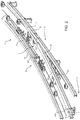
- Number 1 in Figure 1 indicates as a whole a cable transportation system for moving transportation units (not shown in the attached drawings) along a track 2 comprising a junction 3.
- Track 2 is defined by outer fixed guides 4 and 5, by inner fixed guides 6 and 7, and by a switch 8 between outer fixed guides 4 and 5.
- Cable transportation system 1 comprises two haul cables 9 and 10 moved in opposite directions D1 and D2; and the transportation units (not shown) are preferably attachable selectively to one of haul cables 9 and 10.
- Switch 8 comprises a movable guide 11 having one degree of freedom, along the operating plane P, between two given positions; a movable guide 12 having one degree of freedom, along the operating plane P, between two given positions; and a third and fourth movable guide 13 and 14 connected rigidly to each other and having one degree of freedom, along the operating plane P, between two given positions.
- movable guides 11, 12, 13 and 14 are designed so that movable guides 11 and 12 each define a continuation of movable guide 13 or 14.
- movable guide 11 defines an ideal continuation of movable guide 14.
- movable guide 12 defines an ideal continuation of movable guide 13.
- movable guide 11 has a free end adjacent to fixed guide 4. More specifically, fixed guide 4 and movable guide 11 are designed to form a shape fit.
- Movable guide 11 is mounted to rotate about an axis A1 perpendicular to operating plane P with respect to a fixed structure. Movable guide 11 is hinged about axis A1 at the opposite end to its free end.
- movable guide 12 has a free end adjacent to fixed guide 5. More specifically, fixed guide 5 and movable guide 12 are designed to form a shape fit.
- Movable guide 12 is mounted to rotate about an axis A2 perpendicular to operating plane P with respect to a fixed structure. Movable guide 12 is hinged about axis A2 at the opposite end to its free end.
- movable guides 13 and 14 are mounted to rotate about an axis A3 perpendicular to operating plane P.
- fixed guide 7 and movable guides 14 and 11 are aligned to define a section parallel to fixed guide 5.
- fixed guide 6 and movable guides 13 and 12 are aligned to define a section parallel to fixed guide 4.
- axes of rotation A1 and A2 are located along an arc of a circle centred around axis A3.
- cable transportation system 1 comprises an actuating assembly 15 for moving movable guides 11 and 12 between their respective given positions.
- Cable transportation system 1 comprises an actuating assembly 16 for moving movable guides 13 and 14 into their given positions.
- actuating assembly 15 comprises a rotary actuator 17; and a crank 18, which is rotated about an axis A4, perpendicular to operating plane P, by rotary actuator 17.
- Crank 18 is connected to both movable guides 11 and 12 by respective connecting rods 19 and 20, which are hinged at one end to crank 18, and at the other end to respective movable guides 11 and 12.
- Crank 18, movable guides 11 and 12, and connecting rods 19 and 20 define a mechanism with one degree of freedom and controlled by rotary actuator 17.
- the operating configurations of movable guide 11 and movable guide 12 correspond to two stable configurations of the mechanism, and to two limit stop positions of crank 18.
- 'stable configuration' is intended to mean a configuration that is unaffected by external forces acting on movable guides 11 and 12. Obviously, the force applied by crank 18 is not considered one external to the mechanism.
- crank 18 The stability of the mechanism is due to the limit stop positions of crank 18 being located slightly beyond the top dead centre position ( Figure 6 ) and bottom dead centre position ( Figure 4 ).
- crank 18 The opposite limit stops of crank 18 are defined by a fixed catch 21 engaged alternatively by latches 22 and 23 on crank 18.
- actuating assembly 16 comprises a rotary actuator 24; and a crank 25, which is rotated about an axis A5, perpendicular to operating plane P, by rotary actuator 24.
- Crank 25 is connected to movable guides 13 and 14 by a slot 26 engaged slidably by the free end of crank 25. Slot 26 extends between two opposite ends 27.
- Crank 25, movable guides 13 and 14, and the connecting rods define a mechanism with one degree of freedom and controlled by rotary actuator 24.
- the operating configurations of movable guides 13 and 14 correspond to two stable configurations of the mechanism, and to two limit stop positions of crank 25.
- 'stable configuration' is intended to mean a configuration that is unaffected by external forces acting on movable guides 13 and 14. Obviously, the force applied by crank 25 is not considered one external to the mechanism.
- crank 25 The stability of the mechanism is due to the limit stop positions of crank 25 being located slightly beyond the top dead centre position ( Figure 5 ) and bottom dead centre position ( Figure 3 ).
- crank 25 The opposite limit stops of crank 25 are defined by the crank engaging one end 27 of slot 26.
- the present invention makes it possible to form different types of mechanisms, and to operate a number of movable guides using one actuating assembly capable of assuming two stable positions.
Landscapes
- Engineering & Computer Science (AREA)
- Mechanical Engineering (AREA)
- Architecture (AREA)
- Civil Engineering (AREA)
- Structural Engineering (AREA)
- Transportation (AREA)
- Electric Cable Arrangement Between Relatively Moving Parts (AREA)
- Transmission Devices (AREA)
- Ropes Or Cables (AREA)
- Control And Safety Of Cranes (AREA)
Description
- The present invention relates to a cable transportation system for moving transportation units along a given track.
- Cable transportation systems of the above type are described in documents
CH 671,929 AT 404,010 US 5,582,109 ;EP 687,607 AT 405,269 EP 1,077,167 ;EP 1,088,729 ;IT 1,313,914 IT 1,317,169 IT 1,316,131 IT 1,326,531 WO 08/129,019 WO 2009/019,259 ;WO 2009/053,485 . - The tracks of cable transportation systems of the above type sometimes have at least one junction. One particular type of junction is where the track splits into two at a stop station for two vehicles travelling in opposite directions.
- Cable transportation system tracks may comprise two-way and one-way sections, along which the transportation units pass one another in opposite directions.
- Cable transportation systems of the above type comprise two haul cables, which are operated in opposite directions, extend parallel to the track, between two opposite guides, and are connected to the transportation units by clamps integral with the units.
- Cable transportation systems of the above type therefore require switches, which, in addition to ensuring continuity of the track, must also avoid interfering with the haul cable/s and clamps.
- One example of a switch for cable transportation systems of the above type is described in Patent
IT 1,326,531 - Though effective, this type of switch has the drawback of having a very large, extremely heavy moving part, which means switching tracks involves a good deal of travel and, therefore, time.
- Other types of cable transportation system switches are described in Patent Applications
EP 2,407,366 andEP 2,441,636 , in which at least one movable guide, with one degree of freedom along an operating plane, is moved between two given positions by an actuating system comprising a linear actuator. - The switch described in
EP 2,407,366 has the advantage of being extremely simple and minimizing the moving mass, but does not allow for switching tracks along curves. - Conversely, the switch described in
EP 2,441,636 has four movable guides for switching tracks along curves, but has a considerable moving mass that projects outwards of the track. In railways are used switches named switch-frog of the type disclosed inUS 908,037 . - It is an object of the present invention to provide a cable transportation system of the above type, designed to minimize the drawbacks of the known art.
- According to the present invention, there is provided a cable transportation system for moving transportation units along a given track, the cable transportation system comprising a switch in turn comprising a first movable guide having one degree of freedom, along an operating plane, between two given positions; a second movable guide having one degree of freedom, along the operating plane, between two given positions; and a third and a fourth movable guide connected rigidly to each other and having one degree of freedom, along the operating plane, between two given positions; the first, second, third and fourth movable guide being designed so that the first and second movable guide each define a continuation of the third or fourth movable guide, characterized by comprising an actuating assembly connected to the first and second movable guide to move the first and second movable guide between the respective given positions; a rotary actuator; and a crank which rotates, about a fourth axis, between two limit stops, and is connected to the first and second movable guide to define a mechanism movable between two stable positions; a further actuating assembly connected to the third and fourth movable guide to move the third and fourth movable guide between the respective given positions; a further rotary actuator; and a further crank which rotates, about a fifth axis, between two limit stops, and is connected to the third and fourth movable guide to define a mechanism movable between two stable positions.
- In other words, the movable guides are complementary in pairs. Using this principle, connected cornering switches of any design can be formed, by making relatively small movements of relatively short movable guides.
- One actuating assembly is thus capable of advantageously moving two movable guides. The stability of the mechanism positions eliminates the need for locking devices for locking the first and second movable guide in the respective operating configurations.
- In this case, too, the mechanism configuration ensures stability of the third and fourth movable guide operating configurations.
- Preferably, the system comprises an outer first and second fixed guide in the operating plane; the first, second, third and fourth movable guide being located between the first and second fixed guide.
- In no configuration, in fact, does the switch project outwards of the track. Which means the cable transportation system is especially advantageous in tight track space situations.
- Preferably, the first movable guide and the first fixed guide are designed to be positioned adjacent to each other in a first operating configuration.
- The same also applies to the second movable guide: the second movable guide and the second fixed guide are designed to be positioned adjacent to each other in a second operating configuration.
- This way, continuity of the track between fixed and movable guides is achieved.
- In a preferred embodiment, the first and second movable guide rotate respectively about a first and second axis, both perpendicular to the operating plane.
- This makes the movable guides extremely easy to operate.
- Preferably, the third and fourth movable guide rotate about a third axis perpendicular to the operating plane.
- This simplifies operation of the third and fourth movable guide. The system also comprises a third and fourth fixed guide located between the first and second fixed guide and converging towards the third axis. This way, the third fixed guide and third movable guide can be configured to form a continuation of each other.
- Likewise, the fourth fixed guide and fourth movable guide can be configured to form a continuation of each other.
- A non-limiting embodiment of the present invention will be described by way of example with reference to the attached drawings, in which :
-
Figure 1 shows a view in perspective, with parts removed for clarity, of a cable transportation system in accordance with the present invention and in a first operating position; -
Figure 2 shows a view in perspective, with parts removed for clarity, of theFigure 1 system in a second operating position; -
Figure 3 shows a smaller-scale plan view, with parts removed for clarity, of theFigure 1 system; -
Figure 4 shows a larger-scale plan view, with parts removed for clarity, of a detail of theFigure 3 system; -
Figure 5 shows a smaller-scale plan view, with parts removed for clarity, of theFigure 2 system; -
Figure 6 shows a larger-scale plan view, with parts removed for clarity, of a detail of theFigure 5 system. -
Number 1 inFigure 1 indicates as a whole a cable transportation system for moving transportation units (not shown in the attached drawings) along atrack 2 comprising ajunction 3.Track 2 is defined by outerfixed guides fixed guides 6 and 7, and by aswitch 8 between outerfixed guides -
Cable transportation system 1 comprises twohaul cables haul cables -
Switch 8 comprises amovable guide 11 having one degree of freedom, along the operating plane P, between two given positions; amovable guide 12 having one degree of freedom, along the operating plane P, between two given positions; and a third and fourthmovable guide movable guides movable guides movable guide Figure 1 ,movable guide 11 defines an ideal continuation ofmovable guide 14. - In
Figure 2 ,movable guide 12 defines an ideal continuation ofmovable guide 13. - In the
Figure 1 operating configuration,movable guide 11 has a free end adjacent tofixed guide 4. More specifically, fixedguide 4 andmovable guide 11 are designed to form a shape fit. -
Movable guide 11 is mounted to rotate about an axis A1 perpendicular to operating plane P with respect to a fixed structure.Movable guide 11 is hinged about axis A1 at the opposite end to its free end. - In the
Figure 2 operating configuration,movable guide 12 has a free end adjacent tofixed guide 5. More specifically, fixedguide 5 andmovable guide 12 are designed to form a shape fit. -
Movable guide 12 is mounted to rotate about an axis A2 perpendicular to operating plane P with respect to a fixed structure.Movable guide 12 is hinged about axis A2 at the opposite end to its free end. - As shown in
Figures 1 ,2 ,3 and5 ,movable guides - In the
Figure 1 and3 operating configuration, fixedguide 7 andmovable guides fixed guide 5. - In the
Figure 2 and5 operating configuration, fixed guide 6 andmovable guides guide 4. - Preferably, axes of rotation A1 and A2 are located along an arc of a circle centred around axis A3.
- With reference to
Figures 3 and5 ,cable transportation system 1 comprises anactuating assembly 15 for movingmovable guides -
Cable transportation system 1 comprises an actuatingassembly 16 for movingmovable guides - As shown more clearly in
Figures 4 and6 , actuatingassembly 15 comprises arotary actuator 17; and acrank 18, which is rotated about an axis A4, perpendicular to operating plane P, byrotary actuator 17. - Crank 18 is connected to both
movable guides rods crank 18, and at the other end to respectivemovable guides - Crank 18,
movable guides rods rotary actuator 17. - The operating configurations of
movable guide 11 andmovable guide 12 correspond to two stable configurations of the mechanism, and to two limit stop positions ofcrank 18. - The term 'stable configuration' is intended to mean a configuration that is unaffected by external forces acting on
movable guides crank 18 is not considered one external to the mechanism. - The stability of the mechanism is due to the limit stop positions of crank 18 being located slightly beyond the top dead centre position (
Figure 6 ) and bottom dead centre position (Figure 4 ). - The opposite limit stops of crank 18 are defined by a fixed
catch 21 engaged alternatively bylatches - With reference to
Figures 3 and5 , actuatingassembly 16 comprises arotary actuator 24; and acrank 25, which is rotated about an axis A5, perpendicular to operating plane P, byrotary actuator 24. -
Crank 25 is connected tomovable guides slot 26 engaged slidably by the free end ofcrank 25.Slot 26 extends between two opposite ends 27. - Crank 25,
movable guides rotary actuator 24. - The operating configurations of
movable guides crank 25. - The term 'stable configuration' is intended to mean a configuration that is unaffected by external forces acting on
movable guides crank 25 is not considered one external to the mechanism. - The stability of the mechanism is due to the limit stop positions of crank 25 being located slightly beyond the top dead centre position (
Figure 5 ) and bottom dead centre position (Figure 3 ). - The opposite limit stops of crank 25 are defined by the crank engaging one
end 27 ofslot 26. - The present invention makes it possible to form different types of mechanisms, and to operate a number of movable guides using one actuating assembly capable of assuming two stable positions.
- Clearly, changes may be made to the switch described without, however, departing from the scope of the accompanying Claims.
Claims (9)
- A cable transportation system for moving transportation units along a given track, the cable transportation system (1) comprising a switch (8) in turn comprising a first movable guide (11) having one degree of freedom, along an operating plane (P), between two given positions; a second movable guide (12) having one degree of freedom, along the operating plane (P), between two given positions; and a third and a fourth movable guide (13, 14) connected rigidly to each other and having one degree of freedom, along the operating plane (P), between two given positions; the first, second, third and fourth movable guide being designed so that the first and second movable guide (11, 12) each define a continuation of the third or fourth movable guide (13, 14), characterized by comprising an actuating assembly (15) connected to the first and second movable guide (11, 12) to move the first and second movable guide (11, 12) between the respective given positions; a rotary actuator (17); and a crank (18) which rotates, about a fourth axis (A4), between two limit stops, and is connected to the first and second movable guide (11, 12) to define a mechanism movable between two stable positions; a further actuating assembly (16) connected to the third and fourth movable guide (13, 14) to move the third and fourth movable guide (13, 14) between the respective given positions; a further rotary actuator (24); and a further crank (25) which rotates, about a fifth axis (A5), between two limit stops, and is connected to the third and fourth movable guide (13, 14) to define a mechanism movable between two stable positions.
- A system as claimed in Claim 1, and comprising an outer first and second fixed guide (4, 5) in the operating plane (P); the first, second, third and fourth movable guide (11, 12, 13, 14) being located between the first and second fixed guide (4, 5).
- A system as claimed in Claim 2, wherein the first movable guide (11) and the first fixed guide (4) are designed to be positioned adjacent to each other in a first operating configuration.
- A system as claimed in Claim 3, wherein the second movable guide (12) and the second fixed guide (5) are designed to be positioned adjacent to each other in a second operating configuration.
- A system as claimed in any one of the foregoing Claims, wherein the first and second movable guide (11, 12) rotate respectively about a first and second axis (A1, A2), both perpendicular to the operating plane (P).
- A system as claimed in any one of the foregoing Claims, wherein the third and fourth movable guide (13, 14) rotate about a third axis (A3) perpendicular to the operating plane (P).
- A system as claimed in Claim 6, wherein the switch comprises a third and fourth fixed guide (6, 7) located between the first and second fixed guide (4, 5) and converging towards the third axis (A3).
- A system as claimed in Claim 7, wherein the third fixed guide (6) and the third movable guide (13) are designed to define a continuation of each other.
- A system as claimed in Claim 7 or 8, wherein the fourth fixed guide (7) and the fourth movable guide (14) are designed to define a continuation of each other.
Applications Claiming Priority (1)
| Application Number | Priority Date | Filing Date | Title |
|---|---|---|---|
| IT000309A ITMI20130309A1 (en) | 2013-02-28 | 2013-02-28 | ROPE TRANSPORTATION SYSTEM FOR ADVANCED TRANSPORT UNIT ALONG A DETERMINED TRACK |
Publications (2)
| Publication Number | Publication Date |
|---|---|
| EP2772404A1 EP2772404A1 (en) | 2014-09-03 |
| EP2772404B1 true EP2772404B1 (en) | 2017-08-30 |
Family
ID=48096031
Family Applications (1)
| Application Number | Title | Priority Date | Filing Date |
|---|---|---|---|
| EP14157376.6A Active EP2772404B1 (en) | 2013-02-28 | 2014-02-28 | Cable transportation system for moving transportation units along a given track |
Country Status (6)
| Country | Link |
|---|---|
| US (1) | US9315948B2 (en) |
| EP (1) | EP2772404B1 (en) |
| CA (1) | CA2844267C (en) |
| ES (1) | ES2645476T3 (en) |
| IT (1) | ITMI20130309A1 (en) |
| PT (1) | PT2772404T (en) |
Families Citing this family (7)
| Publication number | Priority date | Publication date | Assignee | Title |
|---|---|---|---|---|
| JP5310784B2 (en) * | 2011-05-16 | 2013-10-09 | 村田機械株式会社 | Tracked cart system |
| KR101664630B1 (en) * | 2011-08-31 | 2016-10-11 | 미츠비시 쥬고교 가부시키가이샤 | Vehicle pick-up and delivery device and track-based transportation system provided therewith |
| GB201303948D0 (en) * | 2013-03-05 | 2013-04-17 | Embedded Rail Technology Ltd | Railway junction assembly |
| ITMI20130609A1 (en) * | 2013-04-12 | 2014-10-13 | Rolic Internat S A R L | TROLLEY FOR ROPE TRANSPORTATION SYSTEMS AND ROPE TRANSPORTATION SYSTEM INCLUDING THIS TROLLEY |
| US11097750B2 (en) * | 2017-12-22 | 2021-08-24 | Leitner S.P.A. | Cable transportation system and method for transporting people or goods and clamp for a vehicle of a cable transportation system |
| CN110396875B (en) * | 2018-04-25 | 2021-02-23 | 比亚迪股份有限公司 | Turnout beam driving device, turnout and track |
| CN110745161B (en) * | 2019-11-05 | 2021-08-06 | 重庆华渝重工机电有限公司 | Integral switch type monorail turnout driving method |
Family Cites Families (20)
| Publication number | Priority date | Publication date | Assignee | Title |
|---|---|---|---|---|
| US908037A (en) * | 1907-10-12 | 1908-12-29 | George A Robinson | Switch-frog. |
| US4109584A (en) * | 1976-12-22 | 1978-08-29 | Japan Airlines Co., Limited | Track switching device for two-rail type tracks |
| AT385007B (en) | 1986-04-07 | 1988-02-10 | Voest Alpine Ag | CHASSIS FOR A FUNCTIONAL CABLE CAR |
| AT404010B (en) | 1994-06-09 | 1998-07-27 | Waagner Biro Ag | Truck, in particular pivoted bogie for a rail vehicle such as the wagon of a funicular railway |
| IT1270234B (en) | 1994-06-16 | 1997-04-29 | Leitner Spa | RAILWAY AND TRAENT ROPE FUNICULAR SYSTEM, IN PARTICULAR FOR URBAN TRANSPORT, OF THE TYPE IN WHICH THE VEHICLES ARE EQUIPPED WITH A MOBILE JAW CLAMP FOR ATTACHING / RELEASING FROM THE TRACING ROPE |
| IT1270233B (en) | 1994-06-16 | 1997-04-29 | Leitner Spa | DOUBLE ACTION VICE FOR THE ROPE-RELEASE OF A FUNICULAR VEHICLE |
| AT405269B (en) | 1996-05-24 | 1999-06-25 | Waagner Biro Ag | Funicular railway |
| IT1313108B1 (en) | 1999-08-18 | 2002-06-17 | Leitner Spa | MOBILE JAW VICE PERFECTED FOR THE HOOKING AND RELEASING OF VEHICLES TO A ROPE BETWEEN A TRANSPORT SYSTEM |
| FR2799174A1 (en) * | 1999-09-30 | 2001-04-06 | Pomagalski Sa | DRIVE DEVICE FOR TRANSFER SYSTEM |
| IT1313914B1 (en) | 1999-10-01 | 2002-09-26 | Leitner Spa | PROCEDURE FOR COMMANDING VEHICLES OF A URBAN-DRIVEN TRANSPORT SYSTEM. |
| IT1313913B1 (en) | 1999-10-01 | 2002-09-26 | Leitner Spa | URBAN GUIDED TRANSPORT SYSTEM. |
| IT1317169B1 (en) | 2000-04-05 | 2003-05-27 | Leitner Spa | HORIZONTAL-VERTICAL PLANT FOR PUBLIC TRANSPORT OF PASSENGERS |
| IT1316131B1 (en) | 2000-05-18 | 2003-03-28 | High Technology Investiments B | FUNICULAR TRACTION SYSTEM FOR VEHICLES WITH COUPLING DEVICE AND DECOUPLING OF VEHICLES TO / FROM A ROPE |
| ITMI20070835A1 (en) | 2007-04-20 | 2008-10-21 | Rolic Invest Sarl | ROPE TRANSPORTATION SYSTEM AND METHOD OF OPERATION OF THE SAME |
| ITMI20071618A1 (en) | 2007-08-03 | 2009-02-04 | Rolic Invest Sarl | ROPE TRANSPORTATION SYSTEM AND METHOD OF OPERATION OF THE SAME |
| ITMI20072071A1 (en) | 2007-10-26 | 2009-04-27 | Rolic Invest Sarl | ROPE TRANSPORTATION SYSTEM AND METHOD OF OPERATION OF THE SAME |
| US8302536B1 (en) * | 2008-07-07 | 2012-11-06 | Rofa Rosenheimer Forderanlagen Gmbh | Rail system for a powered pallet conveyor |
| DE202008016678U1 (en) * | 2008-12-17 | 2009-03-12 | Rofa Rosenheimer Förderanlagen GmbH | Switch for an electric pallet railway |
| IT1401120B1 (en) | 2010-07-14 | 2013-07-12 | Rolic Invest Sarl | EXCHANGE FOR ROPE TRANSPORTATION SYSTEM AND ROPE TRANSPORTATION SYSTEM INCLUDING SUCH EXCHANGE. |
| AT12662U1 (en) * | 2010-10-18 | 2012-09-15 | Innova Patent Gmbh | APPENDIX FOR MOVING VEHICLES IN THE LENGTH OF TWO ROADWAYS |
-
2013
- 2013-02-28 IT IT000309A patent/ITMI20130309A1/en unknown
-
2014
- 2014-02-28 PT PT141573766T patent/PT2772404T/en unknown
- 2014-02-28 CA CA2844267A patent/CA2844267C/en active Active
- 2014-02-28 US US14/193,924 patent/US9315948B2/en active Active
- 2014-02-28 ES ES14157376.6T patent/ES2645476T3/en active Active
- 2014-02-28 EP EP14157376.6A patent/EP2772404B1/en active Active
Non-Patent Citations (1)
| Title |
|---|
| None * |
Also Published As
| Publication number | Publication date |
|---|---|
| CA2844267C (en) | 2021-05-11 |
| ES2645476T3 (en) | 2017-12-05 |
| US20140238260A1 (en) | 2014-08-28 |
| CA2844267A1 (en) | 2014-08-28 |
| ITMI20130309A1 (en) | 2014-08-29 |
| US9315948B2 (en) | 2016-04-19 |
| PT2772404T (en) | 2017-11-10 |
| EP2772404A1 (en) | 2014-09-03 |
Similar Documents
| Publication | Publication Date | Title |
|---|---|---|
| CA2844267C (en) | Cable transportation system for moving transportation units along a given track | |
| CA2882692C (en) | Cross-over switch for a monorail | |
| CN103221611B (en) | The Rail Transit System of turnout device and central guiding | |
| US8398031B2 (en) | Rail system, particularly for an electric pallet track | |
| CN1808773A (en) | Device for locking an electric apparatus onto a supporting rail | |
| US10156044B2 (en) | Intersecting track and switching device | |
| US10858788B2 (en) | Monorail switch using a gravity-assisted actuating mechanism | |
| US9410295B2 (en) | Rail system, in particular for an in-floor electric conveyer system | |
| CN112789378A (en) | Rail switch unit | |
| EP2407366B2 (en) | Cable transportation system switch and cable transportation system comprising such a switch | |
| EP2772403B1 (en) | Cable transportation system switch | |
| CN104029696A (en) | Turnout junction switch machine | |
| CA2754926C (en) | System for moving vehicles along two tracks | |
| EP2801503B1 (en) | Cable transportation system for moving transportation units along a given track | |
| CN112211046B (en) | Variable cross section switch beam and straddle type monorail switch with same | |
| CN203567758U (en) | Modular turnout switch machine | |
| CN106876190B (en) | Rotation auxiliary switch for middle voltage switch cabinet | |
| KR101038199B1 (en) | Brake for Line Changer | |
| US20090308713A1 (en) | Diverter | |
| CN108910735A (en) | A kind of electronics clutch driving mechanism and capstan winch | |
| HK40052633A (en) | Rail-switching unit | |
| ITMI20120870A1 (en) | DEVICE FOR THE IMPLEMENTATION OF AN EXCHANGE FOR RAILWAY MODEL | |
| ITFI930106A1 (en) | ACTUATION SYSTEM FOR SWITCH CASE INSIDE THE TRACK. |
Legal Events
| Date | Code | Title | Description |
|---|---|---|---|
| PUAI | Public reference made under article 153(3) epc to a published international application that has entered the european phase |
Free format text: ORIGINAL CODE: 0009012 |
|
| 17P | Request for examination filed |
Effective date: 20140228 |
|
| AK | Designated contracting states |
Kind code of ref document: A1 Designated state(s): AL AT BE BG CH CY CZ DE DK EE ES FI FR GB GR HR HU IE IS IT LI LT LU LV MC MK MT NL NO PL PT RO RS SE SI SK SM TR |
|
| AX | Request for extension of the european patent |
Extension state: BA ME |
|
| RAP1 | Party data changed (applicant data changed or rights of an application transferred) |
Owner name: ROPFIN B.V. |
|
| R17P | Request for examination filed (corrected) |
Effective date: 20150303 |
|
| RBV | Designated contracting states (corrected) |
Designated state(s): AL AT BE BG CH CY CZ DE DK EE ES FI FR GB GR HR HU IE IS IT LI LT LU LV MC MK MT NL NO PL PT RO RS SE SI SK SM TR |
|
| GRAP | Despatch of communication of intention to grant a patent |
Free format text: ORIGINAL CODE: EPIDOSNIGR1 |
|
| INTG | Intention to grant announced |
Effective date: 20170317 |
|
| GRAS | Grant fee paid |
Free format text: ORIGINAL CODE: EPIDOSNIGR3 |
|
| GRAA | (expected) grant |
Free format text: ORIGINAL CODE: 0009210 |
|
| AK | Designated contracting states |
Kind code of ref document: B1 Designated state(s): AL AT BE BG CH CY CZ DE DK EE ES FI FR GB GR HR HU IE IS IT LI LT LU LV MC MK MT NL NO PL PT RO RS SE SI SK SM TR |
|
| REG | Reference to a national code |
Ref country code: GB Ref legal event code: FG4D |
|
| REG | Reference to a national code |
Ref country code: CH Ref legal event code: EP |
|
| REG | Reference to a national code |
Ref country code: AT Ref legal event code: REF Ref document number: 923217 Country of ref document: AT Kind code of ref document: T Effective date: 20170915 |
|
| REG | Reference to a national code |
Ref country code: IE Ref legal event code: FG4D |
|
| REG | Reference to a national code |
Ref country code: DE Ref legal event code: R096 Ref document number: 602014013689 Country of ref document: DE |
|
| REG | Reference to a national code |
Ref country code: CH Ref legal event code: NV Representative=s name: FELBER UND PARTNER AG, CH |
|
| REG | Reference to a national code |
Ref country code: PT Ref legal event code: SC4A Ref document number: 2772404 Country of ref document: PT Date of ref document: 20171110 Kind code of ref document: T Free format text: AVAILABILITY OF NATIONAL TRANSLATION Effective date: 20171026 |
|
| REG | Reference to a national code |
Ref country code: ES Ref legal event code: FG2A Ref document number: 2645476 Country of ref document: ES Kind code of ref document: T3 Effective date: 20171205 |
|
| REG | Reference to a national code |
Ref country code: NL Ref legal event code: MP Effective date: 20170830 |
|
| REG | Reference to a national code |
Ref country code: LT Ref legal event code: MG4D |
|
| PG25 | Lapsed in a contracting state [announced via postgrant information from national office to epo] |
Ref country code: FI Free format text: LAPSE BECAUSE OF FAILURE TO SUBMIT A TRANSLATION OF THE DESCRIPTION OR TO PAY THE FEE WITHIN THE PRESCRIBED TIME-LIMIT Effective date: 20170830 Ref country code: NO Free format text: LAPSE BECAUSE OF FAILURE TO SUBMIT A TRANSLATION OF THE DESCRIPTION OR TO PAY THE FEE WITHIN THE PRESCRIBED TIME-LIMIT Effective date: 20171130 Ref country code: SE Free format text: LAPSE BECAUSE OF FAILURE TO SUBMIT A TRANSLATION OF THE DESCRIPTION OR TO PAY THE FEE WITHIN THE PRESCRIBED TIME-LIMIT Effective date: 20170830 Ref country code: HR Free format text: LAPSE BECAUSE OF FAILURE TO SUBMIT A TRANSLATION OF THE DESCRIPTION OR TO PAY THE FEE WITHIN THE PRESCRIBED TIME-LIMIT Effective date: 20170830 Ref country code: LT Free format text: LAPSE BECAUSE OF FAILURE TO SUBMIT A TRANSLATION OF THE DESCRIPTION OR TO PAY THE FEE WITHIN THE PRESCRIBED TIME-LIMIT Effective date: 20170830 |
|
| REG | Reference to a national code |
Ref country code: DE Ref legal event code: R082 Ref document number: 602014013689 Country of ref document: DE Representative=s name: MUELLER-BORE & PARTNER PATENTANWAELTE PARTG MB, DE Ref country code: DE Ref legal event code: R081 Ref document number: 602014013689 Country of ref document: DE Owner name: LEITNER S.P.A., VIPITENO, IT Free format text: FORMER OWNER: ROPFIN B.V., LEIMUIDEN, NL |
|
| REG | Reference to a national code |
Ref country code: CH Ref legal event code: NV Representative=s name: HEPP WENGER RYFFEL AG, CH Ref country code: CH Ref legal event code: PK Free format text: FELBER UND PARTNER AG WURDE IRRTUEMLICH ALS VERTRETER EINGETRAGEN. |
|
| REG | Reference to a national code |
Ref country code: FR Ref legal event code: PLFP Year of fee payment: 5 |
|
| PG25 | Lapsed in a contracting state [announced via postgrant information from national office to epo] |
Ref country code: GR Free format text: LAPSE BECAUSE OF FAILURE TO SUBMIT A TRANSLATION OF THE DESCRIPTION OR TO PAY THE FEE WITHIN THE PRESCRIBED TIME-LIMIT Effective date: 20171201 Ref country code: IS Free format text: LAPSE BECAUSE OF FAILURE TO SUBMIT A TRANSLATION OF THE DESCRIPTION OR TO PAY THE FEE WITHIN THE PRESCRIBED TIME-LIMIT Effective date: 20171230 Ref country code: BG Free format text: LAPSE BECAUSE OF FAILURE TO SUBMIT A TRANSLATION OF THE DESCRIPTION OR TO PAY THE FEE WITHIN THE PRESCRIBED TIME-LIMIT Effective date: 20171130 Ref country code: RS Free format text: LAPSE BECAUSE OF FAILURE TO SUBMIT A TRANSLATION OF THE DESCRIPTION OR TO PAY THE FEE WITHIN THE PRESCRIBED TIME-LIMIT Effective date: 20170830 Ref country code: LV Free format text: LAPSE BECAUSE OF FAILURE TO SUBMIT A TRANSLATION OF THE DESCRIPTION OR TO PAY THE FEE WITHIN THE PRESCRIBED TIME-LIMIT Effective date: 20170830 |
|
| RAP2 | Party data changed (patent owner data changed or rights of a patent transferred) |
Owner name: LEITNER S.P.A. |
|
| REG | Reference to a national code |
Ref country code: CH Ref legal event code: PUE Owner name: LEITNER S.P.A., IT Free format text: FORMER OWNER: ROPFIN B.V., NL |
|
| REG | Reference to a national code |
Ref country code: ES Ref legal event code: PC2A Owner name: LEITNER S.P.A. Effective date: 20180313 |
|
| REG | Reference to a national code |
Ref country code: GB Ref legal event code: 732E Free format text: REGISTERED BETWEEN 20180301 AND 20180307 |
|
| PG25 | Lapsed in a contracting state [announced via postgrant information from national office to epo] |
Ref country code: NL Free format text: LAPSE BECAUSE OF FAILURE TO SUBMIT A TRANSLATION OF THE DESCRIPTION OR TO PAY THE FEE WITHIN THE PRESCRIBED TIME-LIMIT Effective date: 20170830 |
|
| PG25 | Lapsed in a contracting state [announced via postgrant information from national office to epo] |
Ref country code: DK Free format text: LAPSE BECAUSE OF FAILURE TO SUBMIT A TRANSLATION OF THE DESCRIPTION OR TO PAY THE FEE WITHIN THE PRESCRIBED TIME-LIMIT Effective date: 20170830 Ref country code: PL Free format text: LAPSE BECAUSE OF FAILURE TO SUBMIT A TRANSLATION OF THE DESCRIPTION OR TO PAY THE FEE WITHIN THE PRESCRIBED TIME-LIMIT Effective date: 20170830 Ref country code: CZ Free format text: LAPSE BECAUSE OF FAILURE TO SUBMIT A TRANSLATION OF THE DESCRIPTION OR TO PAY THE FEE WITHIN THE PRESCRIBED TIME-LIMIT Effective date: 20170830 Ref country code: RO Free format text: LAPSE BECAUSE OF FAILURE TO SUBMIT A TRANSLATION OF THE DESCRIPTION OR TO PAY THE FEE WITHIN THE PRESCRIBED TIME-LIMIT Effective date: 20170830 |
|
| PG25 | Lapsed in a contracting state [announced via postgrant information from national office to epo] |
Ref country code: SM Free format text: LAPSE BECAUSE OF FAILURE TO SUBMIT A TRANSLATION OF THE DESCRIPTION OR TO PAY THE FEE WITHIN THE PRESCRIBED TIME-LIMIT Effective date: 20170830 Ref country code: SK Free format text: LAPSE BECAUSE OF FAILURE TO SUBMIT A TRANSLATION OF THE DESCRIPTION OR TO PAY THE FEE WITHIN THE PRESCRIBED TIME-LIMIT Effective date: 20170830 Ref country code: EE Free format text: LAPSE BECAUSE OF FAILURE TO SUBMIT A TRANSLATION OF THE DESCRIPTION OR TO PAY THE FEE WITHIN THE PRESCRIBED TIME-LIMIT Effective date: 20170830 |
|
| REG | Reference to a national code |
Ref country code: DE Ref legal event code: R097 Ref document number: 602014013689 Country of ref document: DE |
|
| REG | Reference to a national code |
Ref country code: AT Ref legal event code: PC Ref document number: 923217 Country of ref document: AT Kind code of ref document: T Owner name: LEITNER S.P.A., IT Effective date: 20180509 |
|
| PLBE | No opposition filed within time limit |
Free format text: ORIGINAL CODE: 0009261 |
|
| REG | Reference to a national code |
Ref country code: FR Ref legal event code: TP Owner name: LEITNER S.P.A., IT Effective date: 20180605 |
|
| STAA | Information on the status of an ep patent application or granted ep patent |
Free format text: STATUS: NO OPPOSITION FILED WITHIN TIME LIMIT |
|
| 26N | No opposition filed |
Effective date: 20180531 |
|
| PG25 | Lapsed in a contracting state [announced via postgrant information from national office to epo] |
Ref country code: SI Free format text: LAPSE BECAUSE OF FAILURE TO SUBMIT A TRANSLATION OF THE DESCRIPTION OR TO PAY THE FEE WITHIN THE PRESCRIBED TIME-LIMIT Effective date: 20170830 |
|
| PG25 | Lapsed in a contracting state [announced via postgrant information from national office to epo] |
Ref country code: MC Free format text: LAPSE BECAUSE OF FAILURE TO SUBMIT A TRANSLATION OF THE DESCRIPTION OR TO PAY THE FEE WITHIN THE PRESCRIBED TIME-LIMIT Effective date: 20170830 |
|
| REG | Reference to a national code |
Ref country code: IE Ref legal event code: MM4A |
|
| REG | Reference to a national code |
Ref country code: BE Ref legal event code: MM Effective date: 20180228 |
|
| PG25 | Lapsed in a contracting state [announced via postgrant information from national office to epo] |
Ref country code: LU Free format text: LAPSE BECAUSE OF NON-PAYMENT OF DUE FEES Effective date: 20180228 |
|
| PG25 | Lapsed in a contracting state [announced via postgrant information from national office to epo] |
Ref country code: IE Free format text: LAPSE BECAUSE OF NON-PAYMENT OF DUE FEES Effective date: 20180228 |
|
| PG25 | Lapsed in a contracting state [announced via postgrant information from national office to epo] |
Ref country code: BE Free format text: LAPSE BECAUSE OF NON-PAYMENT OF DUE FEES Effective date: 20180228 |
|
| REG | Reference to a national code |
Ref country code: AT Ref legal event code: UEP Ref document number: 923217 Country of ref document: AT Kind code of ref document: T Effective date: 20170830 |
|
| PG25 | Lapsed in a contracting state [announced via postgrant information from national office to epo] |
Ref country code: MT Free format text: LAPSE BECAUSE OF NON-PAYMENT OF DUE FEES Effective date: 20180228 |
|
| PG25 | Lapsed in a contracting state [announced via postgrant information from national office to epo] |
Ref country code: TR Free format text: LAPSE BECAUSE OF FAILURE TO SUBMIT A TRANSLATION OF THE DESCRIPTION OR TO PAY THE FEE WITHIN THE PRESCRIBED TIME-LIMIT Effective date: 20170830 |
|
| PGFP | Annual fee paid to national office [announced via postgrant information from national office to epo] |
Ref country code: PT Payment date: 20200207 Year of fee payment: 7 |
|
| PG25 | Lapsed in a contracting state [announced via postgrant information from national office to epo] |
Ref country code: HU Free format text: LAPSE BECAUSE OF FAILURE TO SUBMIT A TRANSLATION OF THE DESCRIPTION OR TO PAY THE FEE WITHIN THE PRESCRIBED TIME-LIMIT; INVALID AB INITIO Effective date: 20140228 |
|
| PGFP | Annual fee paid to national office [announced via postgrant information from national office to epo] |
Ref country code: CH Payment date: 20200225 Year of fee payment: 7 |
|
| PG25 | Lapsed in a contracting state [announced via postgrant information from national office to epo] |
Ref country code: MK Free format text: LAPSE BECAUSE OF NON-PAYMENT OF DUE FEES Effective date: 20170830 Ref country code: CY Free format text: LAPSE BECAUSE OF FAILURE TO SUBMIT A TRANSLATION OF THE DESCRIPTION OR TO PAY THE FEE WITHIN THE PRESCRIBED TIME-LIMIT Effective date: 20170830 |
|
| PG25 | Lapsed in a contracting state [announced via postgrant information from national office to epo] |
Ref country code: AL Free format text: LAPSE BECAUSE OF FAILURE TO SUBMIT A TRANSLATION OF THE DESCRIPTION OR TO PAY THE FEE WITHIN THE PRESCRIBED TIME-LIMIT Effective date: 20170830 |
|
| PG25 | Lapsed in a contracting state [announced via postgrant information from national office to epo] |
Ref country code: CH Free format text: LAPSE BECAUSE OF NON-PAYMENT OF DUE FEES Effective date: 20210228 Ref country code: LI Free format text: LAPSE BECAUSE OF NON-PAYMENT OF DUE FEES Effective date: 20210228 |
|
| PG25 | Lapsed in a contracting state [announced via postgrant information from national office to epo] |
Ref country code: PT Free format text: LAPSE BECAUSE OF NON-PAYMENT OF DUE FEES Effective date: 20210831 |
|
| PGFP | Annual fee paid to national office [announced via postgrant information from national office to epo] |
Ref country code: ES Payment date: 20230321 Year of fee payment: 10 |
|
| P01 | Opt-out of the competence of the unified patent court (upc) registered |
Effective date: 20230524 |
|
| REG | Reference to a national code |
Ref country code: ES Ref legal event code: FD2A Effective date: 20250404 |
|
| PG25 | Lapsed in a contracting state [announced via postgrant information from national office to epo] |
Ref country code: ES Free format text: LAPSE BECAUSE OF NON-PAYMENT OF DUE FEES Effective date: 20240301 |
|
| PGFP | Annual fee paid to national office [announced via postgrant information from national office to epo] |
Ref country code: GB Payment date: 20260223 Year of fee payment: 13 |
|
| PGFP | Annual fee paid to national office [announced via postgrant information from national office to epo] |
Ref country code: DE Payment date: 20260220 Year of fee payment: 13 |
|
| PGFP | Annual fee paid to national office [announced via postgrant information from national office to epo] |
Ref country code: AT Payment date: 20260218 Year of fee payment: 13 |
|
| PGFP | Annual fee paid to national office [announced via postgrant information from national office to epo] |
Ref country code: IT Payment date: 20260203 Year of fee payment: 13 |
|
| PGFP | Annual fee paid to national office [announced via postgrant information from national office to epo] |
Ref country code: FR Payment date: 20260227 Year of fee payment: 13 |