EP2772165A1 - Precision warming bowl - Google Patents
Precision warming bowl Download PDFInfo
- Publication number
- EP2772165A1 EP2772165A1 EP14156947.5A EP14156947A EP2772165A1 EP 2772165 A1 EP2772165 A1 EP 2772165A1 EP 14156947 A EP14156947 A EP 14156947A EP 2772165 A1 EP2772165 A1 EP 2772165A1
- Authority
- EP
- European Patent Office
- Prior art keywords
- heating
- disposed
- cradle
- heating element
- conductive
- Prior art date
- Legal status (The legal status is an assumption and is not a legal conclusion. Google has not performed a legal analysis and makes no representation as to the accuracy of the status listed.)
- Granted
Links
Images




Classifications
-
- A—HUMAN NECESSITIES
- A47—FURNITURE; DOMESTIC ARTICLES OR APPLIANCES; COFFEE MILLS; SPICE MILLS; SUCTION CLEANERS IN GENERAL
- A47J—KITCHEN EQUIPMENT; COFFEE MILLS; SPICE MILLS; APPARATUS FOR MAKING BEVERAGES
- A47J27/00—Cooking-vessels
- A47J27/004—Cooking-vessels with integral electrical heating means
-
- B—PERFORMING OPERATIONS; TRANSPORTING
- B01—PHYSICAL OR CHEMICAL PROCESSES OR APPARATUS IN GENERAL
- B01F—MIXING, e.g. DISSOLVING, EMULSIFYING OR DISPERSING
- B01F35/00—Accessories for mixers; Auxiliary operations or auxiliary devices; Parts or details of general application
- B01F35/90—Heating or cooling systems
- B01F35/92—Heating or cooling systems for heating the outside of the receptacle, e.g. heated jackets or burners
-
- A—HUMAN NECESSITIES
- A47—FURNITURE; DOMESTIC ARTICLES OR APPLIANCES; COFFEE MILLS; SPICE MILLS; SUCTION CLEANERS IN GENERAL
- A47J—KITCHEN EQUIPMENT; COFFEE MILLS; SPICE MILLS; APPARATUS FOR MAKING BEVERAGES
- A47J43/00—Implements for preparing or holding food, not provided for in other groups of this subclass
- A47J43/04—Machines for domestic use not covered elsewhere, e.g. for grinding, mixing, stirring, kneading, emulsifying, whipping or beating foodstuffs, e.g. power-driven
- A47J43/044—Machines for domestic use not covered elsewhere, e.g. for grinding, mixing, stirring, kneading, emulsifying, whipping or beating foodstuffs, e.g. power-driven with tools driven from the top side
-
- A—HUMAN NECESSITIES
- A47—FURNITURE; DOMESTIC ARTICLES OR APPLIANCES; COFFEE MILLS; SPICE MILLS; SUCTION CLEANERS IN GENERAL
- A47J—KITCHEN EQUIPMENT; COFFEE MILLS; SPICE MILLS; APPARATUS FOR MAKING BEVERAGES
- A47J36/00—Parts, details or accessories of cooking-vessels
- A47J36/24—Warming devices
- A47J36/2483—Warming devices with electrical heating means
-
- A—HUMAN NECESSITIES
- A47—FURNITURE; DOMESTIC ARTICLES OR APPLIANCES; COFFEE MILLS; SPICE MILLS; SUCTION CLEANERS IN GENERAL
- A47J—KITCHEN EQUIPMENT; COFFEE MILLS; SPICE MILLS; APPARATUS FOR MAKING BEVERAGES
- A47J43/00—Implements for preparing or holding food, not provided for in other groups of this subclass
- A47J43/04—Machines for domestic use not covered elsewhere, e.g. for grinding, mixing, stirring, kneading, emulsifying, whipping or beating foodstuffs, e.g. power-driven
- A47J43/07—Parts or details, e.g. mixing tools, whipping tools
- A47J43/0727—Mixing bowls
Definitions
- the present application generally relates to mixing bowls, and more specifically, to a mixing bowl with a precision heating feature.
- a warming container in one aspect, includes a mixing bowl and a heating cradle configured to receive the mixing bowl.
- the warming container also includes a shell having an inner-facing surface and which is coupled to a lower edge of the heating cradle at a seat.
- the seat is configured to receive a base of the mixing bowl.
- a cavity is defined between the heating cradle and the shell and a conductive heating structure is disposed within the cavity.
- the conductive heating structure includes a plurality of conductive longitudinal flanges.
- a wire heating element is disposed about the plurality of conductive longitudinal flanges, wherein the wire heating element is disposed about the conductive heating structure in a sinusoidal configuration. The wire heating element is in thermal communication with the heating cradle via the conductive longitudinal flanges.
- the warming container for a mixing bowl includes a heating cradle having a bottom edge and an outer surface.
- a conductive heating structure is disposed proximate the outer surface of the heating cradle and a heating element is coupled with the conductive heating structure, wherein the heating element is in thermal communication with the heating cradle.
- the warming container also includes a shell having an inner-facing surface and is coupled to the lower edge of the heating cradle.
- a cavity is defined between the outer surface of the heating cradle and the inner-facing surface of the shell, wherein the conductive heating structures and the heating element are disposed within the cavity.
- the warming container includes a mixing bowl and a heating cradle configured to receive the mixing bowl.
- a plurality of conductive longitudinal flanges is disposed about the heating cradle and a wire heating element is disposed about the plurality of conductive longitudinal flanges.
- the wire heating element is disposed about the plurality of conductive longitudinal flanges in a sinusoidal configuration, wherein the wire heating element is in thermal communication with the heating cradle via the plurality of conductive longitudinal flanges.
- the warming container also includes a shell coupled to a lower edge of the heating cradle at a seat. The seat is configured to receive a base of the mixing bowl, wherein the heating cradle is in selective thermal communication with the mixing bowl.
- a rim member is coupled to a top edge of the heating cradle and a top edge of the shell, and a cavity is defined between the rim member, the shell and the heating cradle, wherein the plurality of arcuate flanges and the wire heating element are disposed within the cavity.
- the reference numeral 10 generally refers to a warming container 10 that includes a mixing bowl 12 and a heating cradle 14 configured to receive the mixing bowl 12.
- a shell 16 having an inner-facing surface 18 is coupled to a lower edge 20 of the heating cradle 14 at a seat 22.
- the seat 22 is configured to receive a base 24 of the mixing bowl 12.
- a cavity 26 is defined between the heating cradle 14 and the shell 16 and a conductive heating structure is disposed within the cavity 26.
- the conductive heating structure includes a plurality of conductive longitudinal flanges 28.
- a wire heating element 30 is disposed about the plurality of conductive longitudinal flanges 28 in a sinusoidal configuration such that the wire heating element 30 is in thermal communication with the heating cradle 14 via the plurality of conductive longitudinal flanges 28.
- a rim member 40 is coupled with a top edge 42 of the shell 16 and an upper edge 44 of the heating cradle 14 to further define the cavity 26 between the shell 16, the heating cradle 14 and the rim member 40.
- the rim member 40 includes an inner wall 46 disposed proximate the upper edge 44 of the heating cradle 14, an outer wall 48 disposed proximate the top edge 42 of the shell 16, and a top wall 50 that extends between the inner wall 46 and the outer wall 48.
- the shell 16 includes an external surface 60 having a substantially hemispheric configuration, and including a service channel 62 that defines an expanded cavity portion 64 for housing electrical and mechanical aspects, that can include, but are not limited to, a control 66 and an electrical receptacle 68 for operating the various functions of the warming container 10.
- a plurality of orienting receptacles 70 and a switch opening 72 are defined within the service channel 62. As will be more fully described below, in alternate embodiments, the plurality of orienting receptacles 70 and the switch opening 72 can provide an external access point for the warming container 10 to be placed in operable communication with an appliance 74 (shown in FIGS. 11-14 ), or for a user to manipulate the control 66 to operate the various functions of the warming container 10.
- the service channel 62 is configured to receive the electrical receptacle 68, which is disposed proximate the seat 22.
- a receptacle opening 80 defined by the service channel 62 is configured to receive the electrical receptacle 68.
- the electrical receptacle 68 is configured to receive and be in communication with an electrical connector of the appliance 74 such that the warming container 10 can be placed in fluid communication with and receive electrical power from the appliance 74.
- the electrical receptacle 68 can be configured to receive an electrical connection from a different external power source, which can include, but is not limited to, a household or commercial grade electrical outlet.
- the electrical receptacle 68 can rotate within the receptacle opening 80 to account for movements of the warming container 10. In this manner, the warming container 10 can be shifted or otherwise moved small distances relative to the appliance 74 without disconnecting the electrical receptacle 68 from the electrical connector.
- first and second support members 90, 92 are disposed on the external surface 60 of the shell 16.
- the first and second support members 90, 92 are configured to be spaced approximately 180° apart.
- Each of the first and second support members 90, 92 includes a support receptacle 94 on an underside of each of the first and second support members 90, 92.
- Each support receptacle 94 is configured to engage a portion of the appliance 74 whereby the appliance 74 can support the warming container 10 in a fixed position proximate the appliance 74.
- the first and second support members 90, 92 can be separate pieces that are attached directly to the external surface 60 of the shell 16.
- first and second support members 90, 92 can include portions that are formed as part of the shell 16, where the support receptacles 94 are disposed within the first and second support members 90, 92.
- the shell 16 can include a handle disposed on the exterior surface 60 of the shell 16.
- the shell 16 of the warming container 10 can be made of a substantially formable material, including, but not limited to, metals, plastics, ceramics, or other formable material that is substantially sturdy and can support the weight of the warming container 10 and contents placed within the mixing bowl 12 of the warming container 10.
- the heating cradle 14 is disposed within the shell 16 and the lower edge 20 of the heating cradle 14 is coupled to a bottom edge 100 of the shell 16 to form the seat 22.
- the seat 22 defines an oculus 102 of the warming container 10 that is configured to receive the base 24 of the mixing bowl 12.
- the heating cradle 14 includes a flared bottom 104 that extends substantially downward from a concave wall 106 of the heating cradle 14.
- the flared bottom 104 couples proximate the bottom edge 100 of the shell 16, wherein the bottom edge 100 of the shell 16 includes a plurality of oculus protuberances 108 that are configured to receive the flared bottom 104 of the heating cradle 14.
- the flared bottom 104 of the heating cradle 14 has a thicker cross-sectional thickness than the concave wall 106 of the heating cradle 14. In this manner, the flared bottom 104 provides a widened base to support the heating cradle 14 on a plurality of oculus protuberances 108.
- the upper edge 44 of the heating cradle 14 is disposed proximate the top edge 42 of the shell 16, wherein the rim member 40 is coupled to the upper edge 44 of the heating cradle 14 and the top edge 42 of the shell 16 to define an upper surface 110 of the warming container 10.
- the cavity 26 is defined between the inner-facing surface 18 of the shell 16, an outer surface 112 of the heating cradle 14, and an inward surface 114 of the rim member 40.
- the upper edge 44 of the heating cradle 14 includes an upper flange 120 that extends from the concave wall 106 of the heating cradle 14 and defines an annular notch 122 that is configured to receive an annular edge 124 of the inner wall 46 of the rim member 40.
- the annular edge 124 of the rim member 40 is configured to engage at least a portion of the upper flange 120 of the heating cradle 14.
- the inner wall 46 of the rim member 40 extends substantially upward from the annular edge 124 to the top wall 50, wherein the top wall 50 extends orthogonally and outward from the inner wall 46 to the outer wall 48 of the rim member 40.
- the outer wall 48 extends orthogonally and downward from the top wall 50 and is configured to engage at least a portion of the external surface 60 of the shell 16.
- the rim member 40 can include an integrated pour spout that can work in cooperation with a pour spout of the mixing bowl 12.
- the rim member 40 can be made of substantially formable materials that are at least partially heat conductive. Such materials can include, but are not limited to, metals, glass, ceramics, plastics, and other at least partially heat conductive materials. In alternate embodiments, the rim member 40 can be made of substantially heat resistant materials.
- the plurality of conductive longitudinal flanges 28 are disposed within the cavity 26 and proximate the outer surface 112 of the heating cradle 14.
- the plurality of conductive longitudinal flanges 28 can have an arcuate shape that follows the curvature of the concave wall 106 of the heating cradle 14, and can be disposed about the outer surface 112 of the heating cradle 14.
- Each of the plurality of conductive longitudinal flanges 28 includes a first end 130 that is distal from the upper flange 120.
- Each of the plurality of longitudinal flanges 26 extends along the outer surface 112 of the heating cradle 14 and downward to a second end 132 that is disposed distal from the flared bottom 104 of the heating cradle 14.
- the plurality of conductive longitudinal flanges 28 are configured to be in thermal communication with the heating cradle 14.
- the first and second ends 130, 132 of the plurality of conductive longitudinal flanges 28 each define a spur 134 that is configured to receive at least a portion of the wire heating element 30.
- the wire heating element 30 can be wound about the plurality of conductive heating flanges 28 in an undulating pattern and held in place by each of the plurality of longitudinal flanges 28 by at least one spur 134 disposed on the first and second ends 130, 132 of each of the plurality of conductive longitudinal flanges 28.
- the conductive heating structure can include a plurality of arcuate flanges that are disposed longitudinally about the outer surface 112 of the heating cradle 14.
- the plurality of arcuate flanges can be configured to have a "T" cross-section or "L" cross-section that includes an outer flange.
- the outer flange can define the spur 134 around which the wire heating element 30 is disposed and secured to the outer surface 112 of the heating cradle 14.
- the heating cradle 14 can be made of a formable and thermally conductive material, such as metal.
- the plurality of conductive longitudinal flanges 28 can also be made of metal and can be formed as part of a heating cradle 14, or, in alternate embodiments, can be attached as separate elements to the outer surface 112 of the heating cradle 14.
- the heating cradle 14 may be made of other thermally conductive and formable materials that include, but are not limited to, glass, ceramics, or another thermally conductive material.
- the plurality of conductive longitudinal flanges 28 can also be integrally formed with the heating cradle 14 or can be separate members that are attached to the outer surface 112 of the heating cradle 14.
- the wire heating element 30 is disposed within the cavity 26 about the plurality of conductive longitudinal flanges 28, wherein the wire heating element 30 is disposed about the plurality of conductive longitudinal flanges 28 in a sinusoidal configuration.
- the wire heating element 30 is configured to be disposed about the heating cradle 14, such that the wire heating element 30 can provide consistent levels of heating throughout the heating cradle 14.
- the wire heating element 30 can include a resistance value of from 10-20 K ohms. In alternate embodiments, different resistance values can be used based upon various configurations of the warming container 10, and various electricity levels used during the operation of the warming container 10.
- the resistance of the wire heating element 30 is configured to achieve a wattage output of 16-17 W of power for each lineal foot of the wire heating element 30 or approximately 50 W/m output.
- the wire heating element 30 can contain approximately 2.6 m of wire, which will draw approximately 120-150 W of power.
- the input power provided to ingredients disposed within the mixing bowl 12 will be approximately 60-90 W of power.
- the wire heating element 30 can be configured to cooperate with the control 66 and the electrical receptacle 68 to provide stable levels of heating to the heating cradle 14.
- the conductive heating structure can include a plurality of lateral flange rings that extend outward from the outer surface 112 of the heating cradle 14.
- the wire heating element 30 would be wound laterally about the outer surface 112 of the heating cradle 14 and coupled to the flange rings to create a spiral pattern of the wire heating element 30 about the outer surface 112 of the heating cradle 14.
- a thermally conductive and adhesive foil membrane can be configured to engage the wire heating element 30 and dispose the wire heating element 30 to the outer surface 112 of the heating cradle 14, such that the foil membrane and the wire heating element 30 are in thermal communication with the heating cradle 14.
- the bottom edge 100 of the shell 16 and the lower edge 20 of the heating cradle 14 include the seat 22 which defines the oculus 102 into which the base 24 of the mixing bowl 12 can be disposed.
- the mixing bowl 12 is placed in selective thermal communication with an inner surface 150 of the heating cradle 14.
- the plurality of oculus protuberances 108 are disposed on the seat 22 proximate the bottom edge 100 of the shell 16.
- the plurality of oculus protuberances 108 selectively and matingly cooperate with a plurality of engagement protuberances 154 disposed proximate the base 24 of the mixing bowl 12.
- the plurality of oculus protuberances 108 and the plurality of engagement protuberances 154 are configured to couple the base 24 of the mixing bowl 12 within the oculus 102 defined by the seat 22 such that the mixing bowl 12 is secured within the warming container 10.
- the plurality of engagement protuberances 154 can include a substantially vertical portion 160 that is configured to be selectively disposed between the plurality of oculus protuberances 108.
- the plurality of engagement protuberances 154 can also include an inclined portion 162 that slidably engages the plurality of oculus protuberances 108 to upwardly bias the mixing bowl 12 and selectively secure the mixing bowl 12 within the warming container 10.
- the mixing bowl 12 includes a substantially hemispheric sidewall 170 connected to a bottom wall 172, wherein the bottom wall 172 includes a center protuberance 174 that extends from the bottom wall 172.
- the mixing bowl 12 can also include a flared lip 176 that selectively extends, at least partially, over the rim member 40 of the warming container 10, wherein the flared lip 176 can include a rolled member 178.
- the base 24 of the mixing bowl 12 is coupled to the mixing bowl 12 proximate the bottom wall 172 and includes an inner portion 190 having a top surface 192 that includes a secondary protuberance 194.
- the secondary protuberance 194 is configured to be matingly disposed proximate the center protuberance 174 of the bottom wall 172 of the mixing bowl 12.
- the base 24 of the mixing bowl 12 also includes a coupling ring 196 that surrounds and couples to the inner portion 190, wherein an outer member 198 of the coupling ring 196 includes the plurality of engagement protrusions 154.
- the coupling ring 196 is engaged proximate the sidewall 170 and the bottom wall 172 of the mixing bowl 12.
- the mixing bowl 12 can be made of materials that are substantially thermally conductive, and which include, but are not limited to, metals, glass, ceramics, and other thermally conductive materials.
- the control 66 is disposed within the expanded cavity portion 64 defined by the service channel 62 of the shell 16.
- the control 66 includes a switch 200 configured to be disposed through the switch opening 72 defined by the service channel 62, such that an external control can be coupled with the switch 200 and the plurality of orienting receptacles 70 and placed in communication with the switch 200 to permit the external control to selectively regulate the voltage provided to the wire heating element 30 and, in turn, regulate the amount of heating provided to the mixing bowl 12.
- the control 66 is configured to be in communication with the electrical receptacle 68 and the wire heating element 30, and the electrical receptacle 68 is configured to be in communication with the control 66 and the wire heating element 30.
- the control 66 includes an open loop infinite control, whereby the infinite control can selectively provide minor increases or decreases in the amount of voltage provided to the wire heating element 30 so as to provide a precise temperature control to regulate the temperature within the mixing bowl 12.
- a closed loop electronic control can be used to generate customer feedback to provide information which may include, but is not limited to, the temperature of items placed within the mixing bowl 12.
- a thermocouple 210 is disposed proximate the bottom wall 172 of the mixing bowl 12, wherein the thermocouple 210 is configured to be in selective communication with the heating cradle 14. In this manner, the thermocouple 210 can monitor the voltage provided to the wire heating element 30 as well as the temperature of items placed within the mixing bowl 12.
- the control 66 can also include a user interface 230 disposed in the external surface 60 of the shell 16, wherein the user interface 230 can control the various functions of the warming container 10, and also provide various information to the user as to the contents of the mixing bowl 12 and temperature information concerning the warming container 10 and contents disposed therein.
- the user interface 230 can include a temperature interface 232 that can include, but is not limited to, a dial, a click knob, a rotating ring, or other rotating interface that can be used to select the desired temperature of an interior 234 of the mixing bowl 12 (shown in FIG 1 ).
- Temperature indicia 236 relating to the selected temperature can include, but is not limited to, a color or tactile interface, or a visual interface surrounding the temperature interface 232, or visual indicia contained within a display 238, such as an LCD or digital display 238, disposed on the exterior surface 60 of the shell 16.
- the temperature interface 232 can also include touch controls, a rocker switch, or other selection method.
- a plurality of selection interfaces 240 can also be disposed in the user interface 230 that can include, but are not limited to, a power interface 242 for turning on and off the warming container 10, a mode interface 244 for selecting a predetermined heating configuration, an initiating/terminating interface 246 for beginning or ending a preselected and predetermined heating configuration, and a program interface 248 for selecting a predetermined heating program related to the amount or type of food that is disposed within the mixing bowl 12.
- the display 238 can also include indicia relating to the plurality of selection interfaces 240 described above.
- the warming container 10 can also include a scale feature 250, wherein the scale feature 250 is disposed proximate the first and second support members 90, 92, and in communication with the mixing bowl 12 and the user interface 230.
- the scale feature 250 monitors the additional pressure exerted on the first and second support members 90, 92 to determine the weight of food materials placed within the mixing bowl 12.
- the display 238 can be configured to provide scale indicia 252 related to the weight of the materials placed within the mixing bowl 12.
- Additional selection interfaces 240 can be included within the user interface 230, which can include, but are not limited to, a power interface 242 for the scale function 250, a units interface 254 to select the desired weight units to be displayed on the display interface 256, and a reset interface 256 that can be used to calibrate the scale function 250.
- the scale feature 250 can be included in a pour shield that is configured to be selectively disposed proximate the flared lip 176 of the mixing bowl 12.
- the pour shield is in communication with the electrical receptacle 68 and the first and second support members 90, 92.
- the scale feature can be, at least partially disposed in the appliance 74.
- all of the electrical functions included within the warming container 10 are in communication with the electrical receptacle 68 disposed within the receptacle opening 80 of the service channel 62 of the shell 16.
- the electrical receptacle 68 can receive electrical power from the appliance 74 that the warming container 10 is coupled with, or directly from an external source of electricity, such as a household or commercial grade electrical outlet.
- data can be transmitted between the warming container 10 and the appliance 74 via the electrical receptacle 68.
- the plurality of orienting receptacles 70 can be configured to be data input receptacles that can be in communication with the control 66.
- the term "coupled” in all of its forms, couple, coupling, coupled, etc. generally means the joining of two components (electrical or mechanical) directly or indirectly to one another. Such joining may be stationary in nature or movable in nature. Such joining may be achieved with the two components (electrical or mechanical) and any additional intermediate members being integrally formed as a single unitary body with one another or with the two components. Such joining may be permanent in nature or may be removable or releasable in nature unless otherwise stated.
Landscapes
- Engineering & Computer Science (AREA)
- Food Science & Technology (AREA)
- Mechanical Engineering (AREA)
- Chemical & Material Sciences (AREA)
- Chemical Kinetics & Catalysis (AREA)
- Devices For Medical Bathing And Washing (AREA)
- Food-Manufacturing Devices (AREA)
- Thermotherapy And Cooling Therapy Devices (AREA)
- Central Heating Systems (AREA)
Abstract
Description
- The present application generally relates to mixing bowls, and more specifically, to a mixing bowl with a precision heating feature.
- In one aspect, a warming container includes a mixing bowl and a heating cradle configured to receive the mixing bowl. The warming container also includes a shell having an inner-facing surface and which is coupled to a lower edge of the heating cradle at a seat. The seat is configured to receive a base of the mixing bowl. A cavity is defined between the heating cradle and the shell and a conductive heating structure is disposed within the cavity. The conductive heating structure includes a plurality of conductive longitudinal flanges. A wire heating element is disposed about the plurality of conductive longitudinal flanges, wherein the wire heating element is disposed about the conductive heating structure in a sinusoidal configuration. The wire heating element is in thermal communication with the heating cradle via the conductive longitudinal flanges.
- In another aspect, the warming container for a mixing bowl includes a heating cradle having a bottom edge and an outer surface. A conductive heating structure is disposed proximate the outer surface of the heating cradle and a heating element is coupled with the conductive heating structure, wherein the heating element is in thermal communication with the heating cradle. The warming container also includes a shell having an inner-facing surface and is coupled to the lower edge of the heating cradle. A cavity is defined between the outer surface of the heating cradle and the inner-facing surface of the shell, wherein the conductive heating structures and the heating element are disposed within the cavity.
- In yet another aspect, the warming container includes a mixing bowl and a heating cradle configured to receive the mixing bowl. A plurality of conductive longitudinal flanges is disposed about the heating cradle and a wire heating element is disposed about the plurality of conductive longitudinal flanges. The wire heating element is disposed about the plurality of conductive longitudinal flanges in a sinusoidal configuration, wherein the wire heating element is in thermal communication with the heating cradle via the plurality of conductive longitudinal flanges. The warming container also includes a shell coupled to a lower edge of the heating cradle at a seat. The seat is configured to receive a base of the mixing bowl, wherein the heating cradle is in selective thermal communication with the mixing bowl. A rim member is coupled to a top edge of the heating cradle and a top edge of the shell, and a cavity is defined between the rim member, the shell and the heating cradle, wherein the plurality of arcuate flanges and the wire heating element are disposed within the cavity.
- These and other features, advantages, and objects will be further understood and appreciated by those skilled in the art upon studying the following specification, claims, and appended drawings.
- In the drawings:
-
FIG. 1 is a top perspective view of one embodiment of the warming container; -
FIG. 2 is a bottom perspective view of the warming container ofFig. 1 ; -
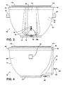
FIG. 3 is a first side elevational view of the warming container ofFig. 1 ; -
FIG. 4 is a second side elevational view of the warming container ofFig. 1 ; -
FIG. 5 is a bottom plan view of the warming container of theFig. 1 ; -
FIG. 6 is a top plan view of the warming container ofFig. 1 ; -
FIG. 7 is a cross-sectional view of the embodiment ofFig. 6 taken at line VII-VII; -
FIG. 8 is an enlarged detail view of the embodiment ofFig. 7 taken at area VIII -
FIG. 9 is a different enlarged detail view of the embodiment ofFig. 7 taken at area IX; -
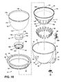
FIG. 10 is an exploded top perspective view of the embodiment ofFig. 1 ; -
FIG. 11 is a front elevational view of another embodiment of the warming container and user interface; -
FIG. 12 is a front elevational view of a different embodiment of the warming container and user interface; -
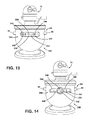
FIG. 13 is a front elevational view of a different embodiment of the warming container and user interface; and -
FIG. 14 is a front elevational view of a different embodiment of the warming container and user interface. - For purposes of description herein the terms "upper," "lower," "right," "left," "rear," "front," "vertical," "horizontal," and derivatives thereof shall relate to the application as oriented in
FIG. 1 . However, it is to be understood that the application may assume various alternative orientations and step sequences, except where expressly specified to the contrary. It is also to be understood that the specific devices and processes illustrated in the attached drawings, and described in the following specification are simply exemplary embodiments of the inventive concepts defined in the appended claims. Hence, specific dimensions and other physical characteristics relating to the embodiments disclosed herein are not to be considered as limiting, unless the claims expressly state otherwise. - As illustrated in
FIGS. 1, 2 and10 , thereference numeral 10 generally refers to awarming container 10 that includes amixing bowl 12 and aheating cradle 14 configured to receive themixing bowl 12. Ashell 16 having an inner-facingsurface 18 is coupled to alower edge 20 of theheating cradle 14 at aseat 22. Theseat 22 is configured to receive abase 24 of themixing bowl 12. Acavity 26 is defined between theheating cradle 14 and theshell 16 and a conductive heating structure is disposed within thecavity 26. The conductive heating structure includes a plurality of conductivelongitudinal flanges 28. Awire heating element 30 is disposed about the plurality of conductivelongitudinal flanges 28 in a sinusoidal configuration such that thewire heating element 30 is in thermal communication with theheating cradle 14 via the plurality of conductivelongitudinal flanges 28. - As illustrated in the embodiment of
FIGS. 1-4 ,6-7 , and9 , arim member 40 is coupled with atop edge 42 of theshell 16 and anupper edge 44 of theheating cradle 14 to further define thecavity 26 between theshell 16, theheating cradle 14 and therim member 40. Therim member 40 includes aninner wall 46 disposed proximate theupper edge 44 of theheating cradle 14, anouter wall 48 disposed proximate thetop edge 42 of theshell 16, and atop wall 50 that extends between theinner wall 46 and theouter wall 48. - As further illustrated in the embodiment of
FIGS. 1-4 ,7 and10 , theshell 16 includes anexternal surface 60 having a substantially hemispheric configuration, and including aservice channel 62 that defines an expandedcavity portion 64 for housing electrical and mechanical aspects, that can include, but are not limited to, acontrol 66 and anelectrical receptacle 68 for operating the various functions of thewarming container 10. A plurality oforienting receptacles 70 and aswitch opening 72 are defined within theservice channel 62. As will be more fully described below, in alternate embodiments, the plurality oforienting receptacles 70 and theswitch opening 72 can provide an external access point for thewarming container 10 to be placed in operable communication with an appliance 74 (shown inFIGS. 11-14 ), or for a user to manipulate thecontrol 66 to operate the various functions of thewarming container 10. - As shown in the embodiment of
FIGS. 2 ,5 and7 , theservice channel 62 is configured to receive theelectrical receptacle 68, which is disposed proximate theseat 22. Areceptacle opening 80 defined by theservice channel 62 is configured to receive theelectrical receptacle 68. Theelectrical receptacle 68 is configured to receive and be in communication with an electrical connector of theappliance 74 such that thewarming container 10 can be placed in fluid communication with and receive electrical power from theappliance 74. In alternate embodiments, theelectrical receptacle 68 can be configured to receive an electrical connection from a different external power source, which can include, but is not limited to, a household or commercial grade electrical outlet. - In alternate embodiments, the
electrical receptacle 68 can rotate within the receptacle opening 80 to account for movements of thewarming container 10. In this manner, thewarming container 10 can be shifted or otherwise moved small distances relative to theappliance 74 without disconnecting theelectrical receptacle 68 from the electrical connector. - Referring again to the embodiment illustrated in
FIGS. 1 and 2 , first andsecond support members external surface 60 of theshell 16. The first andsecond support members second support members support receptacle 94 on an underside of each of the first andsecond support members support receptacle 94 is configured to engage a portion of theappliance 74 whereby theappliance 74 can support thewarming container 10 in a fixed position proximate theappliance 74. The first andsecond support members external surface 60 of theshell 16. Alternatively, the first andsecond support members shell 16, where thesupport receptacles 94 are disposed within the first andsecond support members shell 16 can include a handle disposed on theexterior surface 60 of theshell 16. - As illustrated in the embodiment of
FIGS. 1-5 and7 , theshell 16 of the warmingcontainer 10 can be made of a substantially formable material, including, but not limited to, metals, plastics, ceramics, or other formable material that is substantially sturdy and can support the weight of the warmingcontainer 10 and contents placed within themixing bowl 12 of the warmingcontainer 10. - Referring now to the embodiment illustrated in
FIGS. 7 and 8 , theheating cradle 14 is disposed within theshell 16 and thelower edge 20 of theheating cradle 14 is coupled to abottom edge 100 of theshell 16 to form theseat 22. Theseat 22 defines anoculus 102 of the warmingcontainer 10 that is configured to receive thebase 24 of themixing bowl 12. - As further shown in the embodiment of
FIGS. 7 and 8 , theheating cradle 14 includes a flaredbottom 104 that extends substantially downward from aconcave wall 106 of theheating cradle 14. The flared bottom 104 couples proximate thebottom edge 100 of theshell 16, wherein thebottom edge 100 of theshell 16 includes a plurality ofoculus protuberances 108 that are configured to receive the flaredbottom 104 of theheating cradle 14. The flaredbottom 104 of theheating cradle 14 has a thicker cross-sectional thickness than theconcave wall 106 of theheating cradle 14. In this manner, the flaredbottom 104 provides a widened base to support theheating cradle 14 on a plurality ofoculus protuberances 108. - Referring a to the embodiment illustrated in
FIGS. 7 and 9 , theupper edge 44 of theheating cradle 14 is disposed proximate thetop edge 42 of theshell 16, wherein therim member 40 is coupled to theupper edge 44 of theheating cradle 14 and thetop edge 42 of theshell 16 to define anupper surface 110 of the warmingcontainer 10. In this manner, thecavity 26 is defined between the inner-facingsurface 18 of theshell 16, anouter surface 112 of theheating cradle 14, and aninward surface 114 of therim member 40. - Referring again to
FIG. 9 , in the illustrated embodiment, theupper edge 44 of theheating cradle 14 includes anupper flange 120 that extends from theconcave wall 106 of theheating cradle 14 and defines anannular notch 122 that is configured to receive anannular edge 124 of theinner wall 46 of therim member 40. Theannular edge 124 of therim member 40 is configured to engage at least a portion of theupper flange 120 of theheating cradle 14. Theinner wall 46 of therim member 40 extends substantially upward from theannular edge 124 to thetop wall 50, wherein thetop wall 50 extends orthogonally and outward from theinner wall 46 to theouter wall 48 of therim member 40. Theouter wall 48 extends orthogonally and downward from thetop wall 50 and is configured to engage at least a portion of theexternal surface 60 of theshell 16. In alternate embodiments, therim member 40 can include an integrated pour spout that can work in cooperation with a pour spout of themixing bowl 12. - Referring again to the embodiment of
FIGS. 6-10 , therim member 40 can be made of substantially formable materials that are at least partially heat conductive. Such materials can include, but are not limited to, metals, glass, ceramics, plastics, and other at least partially heat conductive materials. In alternate embodiments, therim member 40 can be made of substantially heat resistant materials. - Referring now to
FIGS. 7-10 , in the illustrated embodiment, the plurality of conductivelongitudinal flanges 28 are disposed within thecavity 26 and proximate theouter surface 112 of theheating cradle 14. The plurality of conductivelongitudinal flanges 28 can have an arcuate shape that follows the curvature of theconcave wall 106 of theheating cradle 14, and can be disposed about theouter surface 112 of theheating cradle 14. Each of the plurality of conductivelongitudinal flanges 28 includes afirst end 130 that is distal from theupper flange 120. Each of the plurality oflongitudinal flanges 26 extends along theouter surface 112 of theheating cradle 14 and downward to asecond end 132 that is disposed distal from the flaredbottom 104 of theheating cradle 14. The plurality of conductivelongitudinal flanges 28 are configured to be in thermal communication with theheating cradle 14. - As illustrated in the embodiment of
FIGS. 7-9 , the first and second ends 130, 132 of the plurality of conductivelongitudinal flanges 28 each define aspur 134 that is configured to receive at least a portion of thewire heating element 30. In this manner, thewire heating element 30 can be wound about the plurality ofconductive heating flanges 28 in an undulating pattern and held in place by each of the plurality oflongitudinal flanges 28 by at least onespur 134 disposed on the first and second ends 130, 132 of each of the plurality of conductivelongitudinal flanges 28. - In alternate embodiments, the conductive heating structure can include a plurality of arcuate flanges that are disposed longitudinally about the
outer surface 112 of theheating cradle 14. In other embodiments, the plurality of arcuate flanges can be configured to have a "T" cross-section or "L" cross-section that includes an outer flange. In this embodiment, the outer flange can define thespur 134 around which thewire heating element 30 is disposed and secured to theouter surface 112 of theheating cradle 14. - Referring again to the illustrated embodiment as shown in
FIGS. 7-10 , theheating cradle 14 can be made of a formable and thermally conductive material, such as metal. In such an embodiment, the plurality of conductivelongitudinal flanges 28 can also be made of metal and can be formed as part of aheating cradle 14, or, in alternate embodiments, can be attached as separate elements to theouter surface 112 of theheating cradle 14. - In other alternate embodiments, the
heating cradle 14 may be made of other thermally conductive and formable materials that include, but are not limited to, glass, ceramics, or another thermally conductive material. In such embodiments, the plurality of conductivelongitudinal flanges 28 can also be integrally formed with theheating cradle 14 or can be separate members that are attached to theouter surface 112 of theheating cradle 14. - Referring again to the embodiment illustrated in
FIGS. 7-10 , thewire heating element 30 is disposed within thecavity 26 about the plurality of conductivelongitudinal flanges 28, wherein thewire heating element 30 is disposed about the plurality of conductivelongitudinal flanges 28 in a sinusoidal configuration. Thewire heating element 30 is configured to be disposed about theheating cradle 14, such that thewire heating element 30 can provide consistent levels of heating throughout theheating cradle 14. In addition, thewire heating element 30 can include a resistance value of from 10-20 K ohms. In alternate embodiments, different resistance values can be used based upon various configurations of the warmingcontainer 10, and various electricity levels used during the operation of the warmingcontainer 10. In the illustrated embodiment, the resistance of thewire heating element 30 is configured to achieve a wattage output of 16-17 W of power for each lineal foot of thewire heating element 30 or approximately 50 W/m output. In this configuration, thewire heating element 30 can contain approximately 2.6 m of wire, which will draw approximately 120-150 W of power. In addition, based upon a heating efficiency of the warmingcontainer 10 of 50-60%, the input power provided to ingredients disposed within themixing bowl 12 will be approximately 60-90 W of power. As will be more fully described below, thewire heating element 30 can be configured to cooperate with thecontrol 66 and theelectrical receptacle 68 to provide stable levels of heating to theheating cradle 14. - In alternate embodiments, the conductive heating structure can include a plurality of lateral flange rings that extend outward from the
outer surface 112 of theheating cradle 14. In such an alternate embodiment, thewire heating element 30 would be wound laterally about theouter surface 112 of theheating cradle 14 and coupled to the flange rings to create a spiral pattern of thewire heating element 30 about theouter surface 112 of theheating cradle 14. - In other alternate embodiments, a thermally conductive and adhesive foil membrane can be configured to engage the
wire heating element 30 and dispose thewire heating element 30 to theouter surface 112 of theheating cradle 14, such that the foil membrane and thewire heating element 30 are in thermal communication with theheating cradle 14. - Referring again to the illustrated embodiment, as shown in
FIGS. 2 ,5 and7 , thebottom edge 100 of theshell 16 and thelower edge 20 of theheating cradle 14 include theseat 22 which defines theoculus 102 into which thebase 24 of themixing bowl 12 can be disposed. In this manner, themixing bowl 12 is placed in selective thermal communication with aninner surface 150 of theheating cradle 14. The plurality ofoculus protuberances 108 are disposed on theseat 22 proximate thebottom edge 100 of theshell 16. The plurality ofoculus protuberances 108 selectively and matingly cooperate with a plurality ofengagement protuberances 154 disposed proximate thebase 24 of themixing bowl 12. The plurality ofoculus protuberances 108 and the plurality ofengagement protuberances 154 are configured to couple thebase 24 of themixing bowl 12 within theoculus 102 defined by theseat 22 such that themixing bowl 12 is secured within the warmingcontainer 10. - As illustrated in the embodiment shown
FIG. 10 , the plurality ofengagement protuberances 154 can include a substantiallyvertical portion 160 that is configured to be selectively disposed between the plurality ofoculus protuberances 108. In addition, the plurality ofengagement protuberances 154 can also include aninclined portion 162 that slidably engages the plurality ofoculus protuberances 108 to upwardly bias themixing bowl 12 and selectively secure themixing bowl 12 within the warmingcontainer 10. - As illustrated in the embodiment of
FIGS. 1 and6-10 , themixing bowl 12 includes a substantiallyhemispheric sidewall 170 connected to abottom wall 172, wherein thebottom wall 172 includes acenter protuberance 174 that extends from thebottom wall 172. Themixing bowl 12 can also include a flaredlip 176 that selectively extends, at least partially, over therim member 40 of the warmingcontainer 10, wherein the flaredlip 176 can include a rolledmember 178. - As illustrated in the embodiment of
FIGS. 7, 8 , and10 , thebase 24 of themixing bowl 12 is coupled to themixing bowl 12 proximate thebottom wall 172 and includes aninner portion 190 having atop surface 192 that includes asecondary protuberance 194. Thesecondary protuberance 194 is configured to be matingly disposed proximate thecenter protuberance 174 of thebottom wall 172 of themixing bowl 12. Thebase 24 of themixing bowl 12 also includes acoupling ring 196 that surrounds and couples to theinner portion 190, wherein anouter member 198 of thecoupling ring 196 includes the plurality ofengagement protrusions 154. Thecoupling ring 196 is engaged proximate thesidewall 170 and thebottom wall 172 of themixing bowl 12. Themixing bowl 12 can be made of materials that are substantially thermally conductive, and which include, but are not limited to, metals, glass, ceramics, and other thermally conductive materials. - As illustrated in
FIGS. 7, 8 , and10 of the illustrated embodiment, thecontrol 66 is disposed within the expandedcavity portion 64 defined by theservice channel 62 of theshell 16. Thecontrol 66 includes aswitch 200 configured to be disposed through the switch opening 72 defined by theservice channel 62, such that an external control can be coupled with theswitch 200 and the plurality of orientingreceptacles 70 and placed in communication with theswitch 200 to permit the external control to selectively regulate the voltage provided to thewire heating element 30 and, in turn, regulate the amount of heating provided to themixing bowl 12. Thecontrol 66 is configured to be in communication with theelectrical receptacle 68 and thewire heating element 30, and theelectrical receptacle 68 is configured to be in communication with thecontrol 66 and thewire heating element 30. - As shown in the embodiment of
FIGS. 7-10 , thecontrol 66 includes an open loop infinite control, whereby the infinite control can selectively provide minor increases or decreases in the amount of voltage provided to thewire heating element 30 so as to provide a precise temperature control to regulate the temperature within themixing bowl 12. In alternate embodiments, a closed loop electronic control can be used to generate customer feedback to provide information which may include, but is not limited to, the temperature of items placed within themixing bowl 12. In such an embodiment, athermocouple 210 is disposed proximate thebottom wall 172 of themixing bowl 12, wherein thethermocouple 210 is configured to be in selective communication with theheating cradle 14. In this manner, thethermocouple 210 can monitor the voltage provided to thewire heating element 30 as well as the temperature of items placed within themixing bowl 12. - Referring now to the illustrated embodiment as shown in
FIGS. 11-14 , thecontrol 66 can also include auser interface 230 disposed in theexternal surface 60 of theshell 16, wherein theuser interface 230 can control the various functions of the warmingcontainer 10, and also provide various information to the user as to the contents of themixing bowl 12 and temperature information concerning the warmingcontainer 10 and contents disposed therein. Theuser interface 230 can include atemperature interface 232 that can include, but is not limited to, a dial, a click knob, a rotating ring, or other rotating interface that can be used to select the desired temperature of an interior 234 of the mixing bowl 12 (shown inFIG 1 ).Temperature indicia 236 relating to the selected temperature can include, but is not limited to, a color or tactile interface, or a visual interface surrounding thetemperature interface 232, or visual indicia contained within adisplay 238, such as an LCD ordigital display 238, disposed on theexterior surface 60 of theshell 16. In alternate embodiments, thetemperature interface 232 can also include touch controls, a rocker switch, or other selection method. A plurality ofselection interfaces 240 can also be disposed in theuser interface 230 that can include, but are not limited to, apower interface 242 for turning on and off the warmingcontainer 10, amode interface 244 for selecting a predetermined heating configuration, an initiating/terminatinginterface 246 for beginning or ending a preselected and predetermined heating configuration, and aprogram interface 248 for selecting a predetermined heating program related to the amount or type of food that is disposed within themixing bowl 12. Thedisplay 238 can also include indicia relating to the plurality of selection interfaces 240 described above. - As further illustrated in the embodiment of
FIGS. 11-14 , the warmingcontainer 10 can also include ascale feature 250, wherein thescale feature 250 is disposed proximate the first andsecond support members mixing bowl 12 and theuser interface 230. In this embodiment, as food materials are placed within themixing bowl 12, thescale feature 250 monitors the additional pressure exerted on the first andsecond support members mixing bowl 12. Thedisplay 238 can be configured to providescale indicia 252 related to the weight of the materials placed within themixing bowl 12. Additional selection interfaces 240 can be included within theuser interface 230, which can include, but are not limited to, apower interface 242 for thescale function 250, aunits interface 254 to select the desired weight units to be displayed on thedisplay interface 256, and areset interface 256 that can be used to calibrate thescale function 250. - In other alternate embodiments, the
scale feature 250 can be included in a pour shield that is configured to be selectively disposed proximate the flaredlip 176 of themixing bowl 12. In such an embodiment, the pour shield is in communication with theelectrical receptacle 68 and the first andsecond support members appliance 74. - In the various embodiments, as illustrated in
FIGS. 7-14 , all of the electrical functions included within the warmingcontainer 10 are in communication with theelectrical receptacle 68 disposed within thereceptacle opening 80 of theservice channel 62 of theshell 16. As discussed above, theelectrical receptacle 68 can receive electrical power from theappliance 74 that the warmingcontainer 10 is coupled with, or directly from an external source of electricity, such as a household or commercial grade electrical outlet. In additional, data can be transmitted between the warmingcontainer 10 and theappliance 74 via theelectrical receptacle 68. In such an embodiment, the plurality of orientingreceptacles 70 can be configured to be data input receptacles that can be in communication with thecontrol 66. - It will be understood by one having ordinary skill in the art that construction of the described application and other components is not limited to any specific material.
- For purposes of this disclosure, the term "coupled" (in all of its forms, couple, coupling, coupled, etc.) generally means the joining of two components (electrical or mechanical) directly or indirectly to one another. Such joining may be stationary in nature or movable in nature. Such joining may be achieved with the two components (electrical or mechanical) and any additional intermediate members being integrally formed as a single unitary body with one another or with the two components. Such joining may be permanent in nature or may be removable or releasable in nature unless otherwise stated.
- It is also important to note that the construction and arrangement of the elements of the application as shown in the exemplary embodiments is illustrative only.
Claims (15)
- A warming container (10) comprising:a mixing bowl (12);a heating cradle (14) configured to receive the mixing bowl (12);a shell (16) having an inner surface (18) and coupled to a lower edge (20) of the heating cradle (14) at a seat (22), wherein the seat is configured to receive a base (24) of the mixing bowl (12);a cavity (26) defined between the heating cradle (14) and the shell (16);a conductive heating structure disposed within the cavity (26), the conductive heating structure including a plurality of conductive longitudinal flanges (28); anda wire heating element (30) disposed about the plurality of conductive longitudinal flanges (28), wherein the wire heating element (30) is disposed about the conductive heating structure in a sinusoidal configuration, and wherein the wire heating element (30) is in thermal communication with the heating cradle (14) via the plurality of conductive longitudinal flanges (28).
- The warming container of claim 1, comprising:a rim member (40) coupled with a top edge (42) of the shell (16) and an upper edge (44) of the heating cradle (14), wherein the rim member (40) at least partially defines the cavity (26).
- The warming container of claim 1, comprising:a thermocouple disposed on an outer surface of the bowl, wherein the thermocouple is in selective fluid communication with the heating cradle (14).
- The warming container of claim 1, comprising:a control (66) at least partially disposed within the cavity proximate the shell (16), wherein the control (66) is in fluid communication with the wire heating element (30).
- The warming container of claim 4, comprising:an electrical receptacle (68) disposed at least partially within the shell (16), wherein the electrical receptacle is in fluid communication with the control (66) and the wire heating element (30), wherein the wire heating element including a resistance value of between 10 and 20 K ohms.
- A warming container of claim 1 wherein the conductive heating structure is disposed proximate the outer surface of the heating cradle (14); a heating element being coupled with the conductive heating structure, wherein the heating element is in thermal communication with the heating cradle (14); the conductive heating structures and the heating element being disposed within the cavity (26).
- The warming container of claim 6, wherein the conductive heating structure comprises a plurality of arcuate flanges disposed longitudinally about the outer surface (112) of the heating cradle (14).
- The warming container of claim 6, wherein the heating element is a wire heating element (30) disposed in an undulating pattern about the conductive heating structure.
- The warming container of claim 6, comprising:a thermocouple selectively removable from an inner facing surface (18) of the heating cradle (14).
- The warming container of claim 6, comprising:a rim member (40) coupled with a top edge (42) of the shell (16) and an upper edge (44) of the heating cradle (14), wherein the rim member at least partially defines the cavity (26).
- A warming container of claim 1, wherein the cavity (26) is defined between the rim member (40), the shell (16) and the heating cradle (14), the plurality of concave longitudinal flanges (28) and the wire heating element (30) being disposed within the cavity (26).
- The warming container of claim 11, wherein the wire heating element (30) includes a resistance value of between 10 and 20 K ohms.
- The warming container of claim 11, comprising:a thermocouple selectively removable from an inner facing surface (18) of the heating cradle (14).
- The warming container of claim 11, comprising:a control (66) at least partially disposed within the cavity (26) proximate the shell (16), wherein the control (66) is in communication with wire heating element (30), an electrical receptacle (68) being disposed on the shell (16), wherein the electrical receptacle (68) is in communication with the control (66) and the wire heating element (30).
- The warming container of claim 18, wherein the control (66) includes an infinite switch.
Applications Claiming Priority (1)
| Application Number | Priority Date | Filing Date | Title |
|---|---|---|---|
| US13/781,901 US9333472B2 (en) | 2013-03-01 | 2013-03-01 | Precision warming bowl |
Publications (2)
| Publication Number | Publication Date |
|---|---|
| EP2772165A1 true EP2772165A1 (en) | 2014-09-03 |
| EP2772165B1 EP2772165B1 (en) | 2015-07-01 |
Family
ID=50272281
Family Applications (1)
| Application Number | Title | Priority Date | Filing Date |
|---|---|---|---|
| EP14156947.5A Not-in-force EP2772165B1 (en) | 2013-03-01 | 2014-02-27 | Precision warming bowl |
Country Status (3)
| Country | Link |
|---|---|
| US (1) | US9333472B2 (en) |
| EP (1) | EP2772165B1 (en) |
| BR (1) | BR102014004624A2 (en) |
Cited By (2)
| Publication number | Priority date | Publication date | Assignee | Title |
|---|---|---|---|---|
| WO2017194877A1 (en) * | 2016-05-11 | 2017-11-16 | Seb S.A. | Heated bowl for an electrical household system |
| DE102017000418A1 (en) | 2017-01-11 | 2018-07-12 | Mussa Jani | Food processor with cooking function |
Families Citing this family (7)
| Publication number | Priority date | Publication date | Assignee | Title |
|---|---|---|---|---|
| US10660470B2 (en) * | 2016-03-02 | 2020-05-26 | Lam & Sons, Llc | Double walled domed electric roasting oven |
| US10568460B2 (en) * | 2017-10-03 | 2020-02-25 | Lam & Sons, Llc | Portable electric grill having a domed lid and method of use |
| US12029353B2 (en) | 2020-06-23 | 2024-07-09 | Whirlpool Corporation | Mixing bowl assembly |
| USD986678S1 (en) | 2021-06-21 | 2023-05-23 | Whirlpool Corporation | Mixing bowl assembly for a stand mixer |
| USD1011843S1 (en) | 2021-08-16 | 2024-01-23 | Whirlpool Corporation | Mixing bowl for a stand mixer |
| US12226744B2 (en) | 2021-08-16 | 2025-02-18 | Whirlpool Corporation | Mixing bowl for stand mixer with high tolerance pin hole location |
| USD1063505S1 (en) | 2022-10-25 | 2025-02-25 | Whirlpool Corporation | Stand mixer |
Citations (2)
| Publication number | Priority date | Publication date | Assignee | Title |
|---|---|---|---|---|
| EP0248490A2 (en) * | 1986-06-05 | 1987-12-09 | Philips S.p.A. | Automatic electric household appliance for making cheese and by-products thereof |
| US20080257168A1 (en) * | 2007-04-20 | 2008-10-23 | Amy Wolfe | Device for stirring and cooking food |
Family Cites Families (21)
| Publication number | Priority date | Publication date | Assignee | Title |
|---|---|---|---|---|
| US1468615A (en) * | 1923-05-18 | 1923-09-18 | Guttenstein Joseph | Heating attachment for cake mixers |
| US2187888A (en) * | 1936-05-21 | 1940-01-23 | Nachumsohn Irving | Cooking apparatus |
| US2818794A (en) | 1954-08-26 | 1958-01-07 | William C Aslesen | Food warming device |
| US2872562A (en) * | 1956-09-17 | 1959-02-03 | Mcnamara Jack | Cooking utensil |
| US3038058A (en) | 1959-06-25 | 1962-06-05 | Gen Electric | Food warming dish |
| US4024377A (en) * | 1975-09-10 | 1977-05-17 | Lincoln Manufacturing Company, Inc. | Hot well and method of heating |
| US4094446A (en) * | 1976-03-01 | 1978-06-13 | Wyott Corporation | Heated dispenser for hot toppings and the like |
| US4063068A (en) | 1976-08-12 | 1977-12-13 | Minnesota Mining And Manufacturing Company | Food heating and cooking receptacle |
| US4249069A (en) * | 1978-03-03 | 1981-02-03 | Hach Chemical Company | Flask heater assembly |
| SU1521453A1 (en) * | 1987-04-30 | 1989-11-15 | Московский институт народного хозяйства им.Г.В.Плеханова | Arrangement for whipping food products |
| CH674794A5 (en) * | 1988-05-17 | 1990-07-31 | Josef Manfred Seifner | |
| US6867394B2 (en) * | 2001-10-05 | 2005-03-15 | George T. C. Li | Roasting oven with dual heating elements |
| US6686569B2 (en) * | 2001-10-05 | 2004-02-03 | Acorne Enterprises, Llc | Roasting oven with dual heating elements |
| US7012221B2 (en) * | 2001-10-05 | 2006-03-14 | Li George T C | Roasting oven with dual heating elements |
| US6884971B2 (en) * | 2003-01-10 | 2005-04-26 | George T. C. Li | Slow cooker with dual heating elements |
| US7015423B2 (en) * | 2003-05-19 | 2006-03-21 | Joshua Friedman | Heating device for dental material |
| US20060044935A1 (en) * | 2004-08-25 | 2006-03-02 | Benelli Brandon P | Method and system for producing a temperature profile in a food preparation container |
| EP1772086A1 (en) | 2005-10-08 | 2007-04-11 | Electrical Investments Limited | A heated appliance having a removable bowl integrated with thermal sensors |
| US8813635B2 (en) * | 2008-01-17 | 2014-08-26 | Marinela Luminita Dragan | Steam-heat-only, food-preparation bowl structure and related methodology |
| US20090194522A1 (en) | 2008-02-01 | 2009-08-06 | Connolly Kevin P | Cordless warmer |
| US8998158B2 (en) * | 2010-10-28 | 2015-04-07 | Staybowlizer Inc. | Stabilizing device for a receptacle or spherical object |
-
2013
- 2013-03-01 US US13/781,901 patent/US9333472B2/en not_active Expired - Fee Related
-
2014
- 2014-02-26 BR BR102014004624A patent/BR102014004624A2/en not_active Application Discontinuation
- 2014-02-27 EP EP14156947.5A patent/EP2772165B1/en not_active Not-in-force
Patent Citations (2)
| Publication number | Priority date | Publication date | Assignee | Title |
|---|---|---|---|---|
| EP0248490A2 (en) * | 1986-06-05 | 1987-12-09 | Philips S.p.A. | Automatic electric household appliance for making cheese and by-products thereof |
| US20080257168A1 (en) * | 2007-04-20 | 2008-10-23 | Amy Wolfe | Device for stirring and cooking food |
Cited By (5)
| Publication number | Priority date | Publication date | Assignee | Title |
|---|---|---|---|---|
| WO2017194877A1 (en) * | 2016-05-11 | 2017-11-16 | Seb S.A. | Heated bowl for an electrical household system |
| FR3051107A1 (en) * | 2016-05-11 | 2017-11-17 | Seb Sa | HEATED BOWL FOR AN ELECTRICAL HOUSEHOLD SYSTEM |
| CN109068897A (en) * | 2016-05-11 | 2018-12-21 | Seb公司 | Heating bowl for appliance system |
| CN109068897B (en) * | 2016-05-11 | 2021-06-25 | Seb公司 | Heating bowl for household appliance system |
| DE102017000418A1 (en) | 2017-01-11 | 2018-07-12 | Mussa Jani | Food processor with cooking function |
Also Published As
| Publication number | Publication date |
|---|---|
| US9333472B2 (en) | 2016-05-10 |
| EP2772165B1 (en) | 2015-07-01 |
| BR102014004624A2 (en) | 2016-04-19 |
| US20140246420A1 (en) | 2014-09-04 |
Similar Documents
| Publication | Publication Date | Title |
|---|---|---|
| EP2772165B1 (en) | Precision warming bowl | |
| US10845774B2 (en) | Cooking device operable to sense an ingredient characteristic and a cooking environment | |
| TWI590794B (en) | Electrical kitchen machine | |
| TWI590795B (en) | Electrical kitchen machine | |
| EP2915411B1 (en) | Microwave oven | |
| CN101909493A (en) | jug and bottom | |
| CN104172899B (en) | The cooking appliance for being used to handle and prepare food with external user interface | |
| KR20190001339U (en) | Cooking System | |
| CN104896535A (en) | Control panel and microwave cooking tool | |
| JP2013075032A (en) | Cooking utensil and cooking utensil system | |
| US20090095732A1 (en) | Multi-Functional Cooker | |
| US11805940B2 (en) | Food processor for controlling another household appliance | |
| CN204541731U (en) | Intelligence cooking appliance | |
| US10226146B1 (en) | Electric cooking system and a cooking method using the same | |
| EP2454980A1 (en) | Food processor | |
| US20090194522A1 (en) | Cordless warmer | |
| KR101544341B1 (en) | A turner receptor for frying pan | |
| CN108209643A (en) | A kind of automatic rice-washing electric cooker | |
| CN208551391U (en) | Cooking apparatus | |
| CN205493512U (en) | Multifunctional electric cooker | |
| CN207561723U (en) | Split cooking apparatus | |
| CN208447209U (en) | cookware | |
| CN206596027U (en) | Control device, server, terminal and the food cooking machine of household electrical appliance | |
| RU152328U1 (en) | ELECTRONICALLY CONTROLLED COOKER AND CALORIC DETERMINATION | |
| CN116919178A (en) | Cooking appliance, control method of cooking appliance and computer readable storage medium |
Legal Events
| Date | Code | Title | Description |
|---|---|---|---|
| PUAI | Public reference made under article 153(3) epc to a published international application that has entered the european phase |
Free format text: ORIGINAL CODE: 0009012 |
|
| 17P | Request for examination filed |
Effective date: 20140227 |
|
| AK | Designated contracting states |
Kind code of ref document: A1 Designated state(s): AL AT BE BG CH CY CZ DE DK EE ES FI FR GB GR HR HU IE IS IT LI LT LU LV MC MK MT NL NO PL PT RO RS SE SI SK SM TR |
|
| AX | Request for extension of the european patent |
Extension state: BA ME |
|
| R17P | Request for examination filed (corrected) |
Effective date: 20150302 |
|
| RBV | Designated contracting states (corrected) |
Designated state(s): AL AT BE BG CH CY CZ DE DK EE ES FI FR GB GR HR HU IE IS IT LI LT LU LV MC MK MT NL NO PL PT RO RS SE SI SK SM TR |
|
| GRAP | Despatch of communication of intention to grant a patent |
Free format text: ORIGINAL CODE: EPIDOSNIGR1 |
|
| RIC1 | Information provided on ipc code assigned before grant |
Ipc: A47J 43/07 20060101AFI20150327BHEP Ipc: A47J 43/044 20060101ALI20150327BHEP |
|
| INTG | Intention to grant announced |
Effective date: 20150422 |
|
| GRAS | Grant fee paid |
Free format text: ORIGINAL CODE: EPIDOSNIGR3 |
|
| GRAA | (expected) grant |
Free format text: ORIGINAL CODE: 0009210 |
|
| AK | Designated contracting states |
Kind code of ref document: B1 Designated state(s): AL AT BE BG CH CY CZ DE DK EE ES FI FR GB GR HR HU IE IS IT LI LT LU LV MC MK MT NL NO PL PT RO RS SE SI SK SM TR |
|
| REG | Reference to a national code |
Ref country code: GB Ref legal event code: FG4D |
|
| REG | Reference to a national code |
Ref country code: AT Ref legal event code: REF Ref document number: 733430 Country of ref document: AT Kind code of ref document: T Effective date: 20150715 Ref country code: CH Ref legal event code: EP |
|
| REG | Reference to a national code |
Ref country code: IE Ref legal event code: FG4D |
|
| REG | Reference to a national code |
Ref country code: DE Ref legal event code: R096 Ref document number: 602014000058 Country of ref document: DE |
|
| REG | Reference to a national code |
Ref country code: AT Ref legal event code: MK05 Ref document number: 733430 Country of ref document: AT Kind code of ref document: T Effective date: 20150701 |
|
| REG | Reference to a national code |
Ref country code: NL Ref legal event code: MP Effective date: 20150701 |
|
| REG | Reference to a national code |
Ref country code: LT Ref legal event code: MG4D |
|
| REG | Reference to a national code |
Ref country code: FR Ref legal event code: PLFP Year of fee payment: 3 |
|
| PG25 | Lapsed in a contracting state [announced via postgrant information from national office to epo] |
Ref country code: GR Free format text: LAPSE BECAUSE OF FAILURE TO SUBMIT A TRANSLATION OF THE DESCRIPTION OR TO PAY THE FEE WITHIN THE PRESCRIBED TIME-LIMIT Effective date: 20151002 Ref country code: NO Free format text: LAPSE BECAUSE OF FAILURE TO SUBMIT A TRANSLATION OF THE DESCRIPTION OR TO PAY THE FEE WITHIN THE PRESCRIBED TIME-LIMIT Effective date: 20151001 Ref country code: LT Free format text: LAPSE BECAUSE OF FAILURE TO SUBMIT A TRANSLATION OF THE DESCRIPTION OR TO PAY THE FEE WITHIN THE PRESCRIBED TIME-LIMIT Effective date: 20150701 Ref country code: FI Free format text: LAPSE BECAUSE OF FAILURE TO SUBMIT A TRANSLATION OF THE DESCRIPTION OR TO PAY THE FEE WITHIN THE PRESCRIBED TIME-LIMIT Effective date: 20150701 Ref country code: LV Free format text: LAPSE BECAUSE OF FAILURE TO SUBMIT A TRANSLATION OF THE DESCRIPTION OR TO PAY THE FEE WITHIN THE PRESCRIBED TIME-LIMIT Effective date: 20150701 |
|
| PG25 | Lapsed in a contracting state [announced via postgrant information from national office to epo] |
Ref country code: SE Free format text: LAPSE BECAUSE OF FAILURE TO SUBMIT A TRANSLATION OF THE DESCRIPTION OR TO PAY THE FEE WITHIN THE PRESCRIBED TIME-LIMIT Effective date: 20150701 Ref country code: ES Free format text: LAPSE BECAUSE OF FAILURE TO SUBMIT A TRANSLATION OF THE DESCRIPTION OR TO PAY THE FEE WITHIN THE PRESCRIBED TIME-LIMIT Effective date: 20150701 Ref country code: PT Free format text: LAPSE BECAUSE OF FAILURE TO SUBMIT A TRANSLATION OF THE DESCRIPTION OR TO PAY THE FEE WITHIN THE PRESCRIBED TIME-LIMIT Effective date: 20151102 Ref country code: HR Free format text: LAPSE BECAUSE OF FAILURE TO SUBMIT A TRANSLATION OF THE DESCRIPTION OR TO PAY THE FEE WITHIN THE PRESCRIBED TIME-LIMIT Effective date: 20150701 Ref country code: PL Free format text: LAPSE BECAUSE OF FAILURE TO SUBMIT A TRANSLATION OF THE DESCRIPTION OR TO PAY THE FEE WITHIN THE PRESCRIBED TIME-LIMIT Effective date: 20150701 Ref country code: AT Free format text: LAPSE BECAUSE OF FAILURE TO SUBMIT A TRANSLATION OF THE DESCRIPTION OR TO PAY THE FEE WITHIN THE PRESCRIBED TIME-LIMIT Effective date: 20150701 Ref country code: IS Free format text: LAPSE BECAUSE OF FAILURE TO SUBMIT A TRANSLATION OF THE DESCRIPTION OR TO PAY THE FEE WITHIN THE PRESCRIBED TIME-LIMIT Effective date: 20151101 Ref country code: RS Free format text: LAPSE BECAUSE OF FAILURE TO SUBMIT A TRANSLATION OF THE DESCRIPTION OR TO PAY THE FEE WITHIN THE PRESCRIBED TIME-LIMIT Effective date: 20150701 |
|
| REG | Reference to a national code |
Ref country code: DE Ref legal event code: R097 Ref document number: 602014000058 Country of ref document: DE |
|
| PG25 | Lapsed in a contracting state [announced via postgrant information from national office to epo] |
Ref country code: DK Free format text: LAPSE BECAUSE OF FAILURE TO SUBMIT A TRANSLATION OF THE DESCRIPTION OR TO PAY THE FEE WITHIN THE PRESCRIBED TIME-LIMIT Effective date: 20150701 Ref country code: CZ Free format text: LAPSE BECAUSE OF FAILURE TO SUBMIT A TRANSLATION OF THE DESCRIPTION OR TO PAY THE FEE WITHIN THE PRESCRIBED TIME-LIMIT Effective date: 20150701 Ref country code: EE Free format text: LAPSE BECAUSE OF FAILURE TO SUBMIT A TRANSLATION OF THE DESCRIPTION OR TO PAY THE FEE WITHIN THE PRESCRIBED TIME-LIMIT Effective date: 20150701 Ref country code: SK Free format text: LAPSE BECAUSE OF FAILURE TO SUBMIT A TRANSLATION OF THE DESCRIPTION OR TO PAY THE FEE WITHIN THE PRESCRIBED TIME-LIMIT Effective date: 20150701 |
|
| PLBE | No opposition filed within time limit |
Free format text: ORIGINAL CODE: 0009261 |
|
| STAA | Information on the status of an ep patent application or granted ep patent |
Free format text: STATUS: NO OPPOSITION FILED WITHIN TIME LIMIT |
|
| PG25 | Lapsed in a contracting state [announced via postgrant information from national office to epo] |
Ref country code: BE Free format text: LAPSE BECAUSE OF NON-PAYMENT OF DUE FEES Effective date: 20160229 Ref country code: RO Free format text: LAPSE BECAUSE OF FAILURE TO SUBMIT A TRANSLATION OF THE DESCRIPTION OR TO PAY THE FEE WITHIN THE PRESCRIBED TIME-LIMIT Effective date: 20150701 |
|
| 26N | No opposition filed |
Effective date: 20160404 |
|
| PG25 | Lapsed in a contracting state [announced via postgrant information from national office to epo] |
Ref country code: SI Free format text: LAPSE BECAUSE OF FAILURE TO SUBMIT A TRANSLATION OF THE DESCRIPTION OR TO PAY THE FEE WITHIN THE PRESCRIBED TIME-LIMIT Effective date: 20150701 |
|
| PG25 | Lapsed in a contracting state [announced via postgrant information from national office to epo] |
Ref country code: MC Free format text: LAPSE BECAUSE OF FAILURE TO SUBMIT A TRANSLATION OF THE DESCRIPTION OR TO PAY THE FEE WITHIN THE PRESCRIBED TIME-LIMIT Effective date: 20150701 Ref country code: LU Free format text: LAPSE BECAUSE OF FAILURE TO SUBMIT A TRANSLATION OF THE DESCRIPTION OR TO PAY THE FEE WITHIN THE PRESCRIBED TIME-LIMIT Effective date: 20160227 |
|
| REG | Reference to a national code |
Ref country code: IE Ref legal event code: MM4A |
|
| PG25 | Lapsed in a contracting state [announced via postgrant information from national office to epo] |
Ref country code: BE Free format text: LAPSE BECAUSE OF FAILURE TO SUBMIT A TRANSLATION OF THE DESCRIPTION OR TO PAY THE FEE WITHIN THE PRESCRIBED TIME-LIMIT Effective date: 20150701 |
|
| REG | Reference to a national code |
Ref country code: FR Ref legal event code: PLFP Year of fee payment: 4 |
|
| PG25 | Lapsed in a contracting state [announced via postgrant information from national office to epo] |
Ref country code: IE Free format text: LAPSE BECAUSE OF NON-PAYMENT OF DUE FEES Effective date: 20160227 |
|
| PG25 | Lapsed in a contracting state [announced via postgrant information from national office to epo] |
Ref country code: NL Free format text: LAPSE BECAUSE OF FAILURE TO SUBMIT A TRANSLATION OF THE DESCRIPTION OR TO PAY THE FEE WITHIN THE PRESCRIBED TIME-LIMIT Effective date: 20150701 |
|
| PG25 | Lapsed in a contracting state [announced via postgrant information from national office to epo] |
Ref country code: MT Free format text: LAPSE BECAUSE OF FAILURE TO SUBMIT A TRANSLATION OF THE DESCRIPTION OR TO PAY THE FEE WITHIN THE PRESCRIBED TIME-LIMIT Effective date: 20150701 |
|
| REG | Reference to a national code |
Ref country code: CH Ref legal event code: PL |
|
| PG25 | Lapsed in a contracting state [announced via postgrant information from national office to epo] |
Ref country code: CH Free format text: LAPSE BECAUSE OF NON-PAYMENT OF DUE FEES Effective date: 20170228 Ref country code: LI Free format text: LAPSE BECAUSE OF NON-PAYMENT OF DUE FEES Effective date: 20170228 |
|
| REG | Reference to a national code |
Ref country code: FR Ref legal event code: PLFP Year of fee payment: 5 |
|
| PG25 | Lapsed in a contracting state [announced via postgrant information from national office to epo] |
Ref country code: SM Free format text: LAPSE BECAUSE OF FAILURE TO SUBMIT A TRANSLATION OF THE DESCRIPTION OR TO PAY THE FEE WITHIN THE PRESCRIBED TIME-LIMIT Effective date: 20150701 Ref country code: CY Free format text: LAPSE BECAUSE OF FAILURE TO SUBMIT A TRANSLATION OF THE DESCRIPTION OR TO PAY THE FEE WITHIN THE PRESCRIBED TIME-LIMIT Effective date: 20150701 Ref country code: HU Free format text: LAPSE BECAUSE OF FAILURE TO SUBMIT A TRANSLATION OF THE DESCRIPTION OR TO PAY THE FEE WITHIN THE PRESCRIBED TIME-LIMIT; INVALID AB INITIO Effective date: 20140227 |
|
| PG25 | Lapsed in a contracting state [announced via postgrant information from national office to epo] |
Ref country code: MK Free format text: LAPSE BECAUSE OF FAILURE TO SUBMIT A TRANSLATION OF THE DESCRIPTION OR TO PAY THE FEE WITHIN THE PRESCRIBED TIME-LIMIT Effective date: 20150701 Ref country code: MT Free format text: LAPSE BECAUSE OF FAILURE TO SUBMIT A TRANSLATION OF THE DESCRIPTION OR TO PAY THE FEE WITHIN THE PRESCRIBED TIME-LIMIT Effective date: 20160229 Ref country code: TR Free format text: LAPSE BECAUSE OF FAILURE TO SUBMIT A TRANSLATION OF THE DESCRIPTION OR TO PAY THE FEE WITHIN THE PRESCRIBED TIME-LIMIT Effective date: 20150701 |
|
| PG25 | Lapsed in a contracting state [announced via postgrant information from national office to epo] |
Ref country code: BG Free format text: LAPSE BECAUSE OF FAILURE TO SUBMIT A TRANSLATION OF THE DESCRIPTION OR TO PAY THE FEE WITHIN THE PRESCRIBED TIME-LIMIT Effective date: 20150701 |
|
| PG25 | Lapsed in a contracting state [announced via postgrant information from national office to epo] |
Ref country code: AL Free format text: LAPSE BECAUSE OF FAILURE TO SUBMIT A TRANSLATION OF THE DESCRIPTION OR TO PAY THE FEE WITHIN THE PRESCRIBED TIME-LIMIT Effective date: 20150701 |
|
| PGFP | Annual fee paid to national office [announced via postgrant information from national office to epo] |
Ref country code: GB Payment date: 20220106 Year of fee payment: 9 Ref country code: DE Payment date: 20220105 Year of fee payment: 9 |
|
| PGFP | Annual fee paid to national office [announced via postgrant information from national office to epo] |
Ref country code: IT Payment date: 20220111 Year of fee payment: 9 Ref country code: FR Payment date: 20220118 Year of fee payment: 9 |
|
| REG | Reference to a national code |
Ref country code: DE Ref legal event code: R119 Ref document number: 602014000058 Country of ref document: DE |
|
| GBPC | Gb: european patent ceased through non-payment of renewal fee |
Effective date: 20230227 |
|
| PG25 | Lapsed in a contracting state [announced via postgrant information from national office to epo] |
Ref country code: GB Free format text: LAPSE BECAUSE OF NON-PAYMENT OF DUE FEES Effective date: 20230227 |
|
| PG25 | Lapsed in a contracting state [announced via postgrant information from national office to epo] |
Ref country code: IT Free format text: LAPSE BECAUSE OF NON-PAYMENT OF DUE FEES Effective date: 20230227 Ref country code: GB Free format text: LAPSE BECAUSE OF NON-PAYMENT OF DUE FEES Effective date: 20230227 Ref country code: FR Free format text: LAPSE BECAUSE OF NON-PAYMENT OF DUE FEES Effective date: 20230228 Ref country code: DE Free format text: LAPSE BECAUSE OF NON-PAYMENT OF DUE FEES Effective date: 20230901 |