EP2771391B1 - Method of forming a release layer - Google Patents
Method of forming a release layer Download PDFInfo
- Publication number
- EP2771391B1 EP2771391B1 EP11781473.1A EP11781473A EP2771391B1 EP 2771391 B1 EP2771391 B1 EP 2771391B1 EP 11781473 A EP11781473 A EP 11781473A EP 2771391 B1 EP2771391 B1 EP 2771391B1
- Authority
- EP
- European Patent Office
- Prior art keywords
- primer
- substrate
- catalyst
- curable
- cured
- Prior art date
- Legal status (The legal status is an assumption and is not a legal conclusion. Google has not performed a legal analysis and makes no representation as to the accuracy of the status listed.)
- Not-in-force
Links
- 238000000034 method Methods 0.000 title claims description 28
- 239000000758 substrate Substances 0.000 claims description 51
- 229920001296 polysiloxane Polymers 0.000 claims description 50
- 239000003054 catalyst Substances 0.000 claims description 40
- BASFCYQUMIYNBI-UHFFFAOYSA-N platinum Chemical compound [Pt] BASFCYQUMIYNBI-UHFFFAOYSA-N 0.000 claims description 31
- 239000000203 mixture Substances 0.000 claims description 26
- 238000009472 formulation Methods 0.000 claims description 20
- 229920001971 elastomer Polymers 0.000 claims description 17
- 239000000463 material Substances 0.000 claims description 17
- 239000005060 rubber Substances 0.000 claims description 16
- RTAQQCXQSZGOHL-UHFFFAOYSA-N Titanium Chemical compound [Ti] RTAQQCXQSZGOHL-UHFFFAOYSA-N 0.000 claims description 15
- 229910052697 platinum Inorganic materials 0.000 claims description 15
- 150000001282 organosilanes Chemical class 0.000 claims description 14
- 238000007645 offset printing Methods 0.000 claims description 11
- 239000010936 titanium Substances 0.000 claims description 11
- 229910052719 titanium Inorganic materials 0.000 claims description 11
- 229920000800 acrylic rubber Polymers 0.000 claims description 9
- 229920000058 polyacrylate Polymers 0.000 claims description 9
- 238000007259 addition reaction Methods 0.000 claims description 7
- 239000003112 inhibitor Substances 0.000 claims description 6
- 125000000391 vinyl group Chemical group [H]C([*])=C([H])[H] 0.000 claims description 6
- 239000004971 Cross linker Substances 0.000 claims description 5
- 238000006482 condensation reaction Methods 0.000 claims description 5
- 229920002554 vinyl polymer Polymers 0.000 claims description 5
- BLRPTPMANUNPDV-UHFFFAOYSA-N Silane Chemical compound [SiH4] BLRPTPMANUNPDV-UHFFFAOYSA-N 0.000 claims description 4
- 239000013522 chelant Substances 0.000 claims description 4
- 239000006229 carbon black Substances 0.000 claims description 3
- 239000004205 dimethyl polysiloxane Substances 0.000 claims description 3
- 235000013870 dimethyl polysiloxane Nutrition 0.000 claims description 3
- 229920000435 poly(dimethylsiloxane) Polymers 0.000 claims description 3
- DNAJDTIOMGISDS-UHFFFAOYSA-N prop-2-enylsilane Chemical compound [SiH3]CC=C DNAJDTIOMGISDS-UHFFFAOYSA-N 0.000 claims description 3
- 150000004756 silanes Chemical class 0.000 claims description 3
- UKRDPEFKFJNXQM-UHFFFAOYSA-N vinylsilane Chemical compound [SiH3]C=C UKRDPEFKFJNXQM-UHFFFAOYSA-N 0.000 claims description 3
- -1 vinylsiloxane Chemical class 0.000 claims description 3
- VMAWODUEPLAHOE-UHFFFAOYSA-N 2,4,6,8-tetrakis(ethenyl)-2,4,6,8-tetramethyl-1,3,5,7,2,4,6,8-tetraoxatetrasilocane Chemical compound C=C[Si]1(C)O[Si](C)(C=C)O[Si](C)(C=C)O[Si](C)(C=C)O1 VMAWODUEPLAHOE-UHFFFAOYSA-N 0.000 claims description 2
- LFQSCWFLJHTTHZ-UHFFFAOYSA-N Ethanol Chemical compound CCO LFQSCWFLJHTTHZ-UHFFFAOYSA-N 0.000 claims description 2
- VYPSYNLAJGMNEJ-UHFFFAOYSA-N Silicium dioxide Chemical compound O=[Si]=O VYPSYNLAJGMNEJ-UHFFFAOYSA-N 0.000 claims description 2
- BITPLIXHRASDQB-UHFFFAOYSA-N ethenyl-[ethenyl(dimethyl)silyl]oxy-dimethylsilane Chemical compound C=C[Si](C)(C)O[Si](C)(C)C=C BITPLIXHRASDQB-UHFFFAOYSA-N 0.000 claims description 2
- 239000000945 filler Substances 0.000 claims description 2
- 239000003446 ligand Substances 0.000 claims description 2
- 229910052990 silicon hydride Inorganic materials 0.000 claims description 2
- 229920002545 silicone oil Polymers 0.000 claims description 2
- KAKZBPTYRLMSJV-UHFFFAOYSA-N vinyl-ethylene Natural products C=CC=C KAKZBPTYRLMSJV-UHFFFAOYSA-N 0.000 claims description 2
- 239000010410 layer Substances 0.000 description 59
- 238000003384 imaging method Methods 0.000 description 18
- 238000001723 curing Methods 0.000 description 13
- 238000007639 printing Methods 0.000 description 11
- 238000000576 coating method Methods 0.000 description 7
- FWDBOZPQNFPOLF-UHFFFAOYSA-N ethenyl(triethoxy)silane Chemical compound CCO[Si](OCC)(OCC)C=C FWDBOZPQNFPOLF-UHFFFAOYSA-N 0.000 description 7
- 101000801643 Homo sapiens Retinal-specific phospholipid-transporting ATPase ABCA4 Proteins 0.000 description 6
- 102100033617 Retinal-specific phospholipid-transporting ATPase ABCA4 Human genes 0.000 description 6
- 238000013006 addition curing Methods 0.000 description 5
- 239000007788 liquid Substances 0.000 description 5
- 229920000642 polymer Polymers 0.000 description 5
- NIXOWILDQLNWCW-UHFFFAOYSA-N acrylic acid group Chemical group C(C=C)(=O)O NIXOWILDQLNWCW-UHFFFAOYSA-N 0.000 description 4
- 238000010586 diagram Methods 0.000 description 4
- BPSIOYPQMFLKFR-UHFFFAOYSA-N trimethoxy-[3-(oxiran-2-ylmethoxy)propyl]silane Chemical compound CO[Si](OC)(OC)CCCOCC1CO1 BPSIOYPQMFLKFR-UHFFFAOYSA-N 0.000 description 4
- 229920000459 Nitrile rubber Polymers 0.000 description 3
- 238000005299 abrasion Methods 0.000 description 3
- 230000004888 barrier function Effects 0.000 description 3
- 238000006243 chemical reaction Methods 0.000 description 3
- 238000013005 condensation curing Methods 0.000 description 3
- 230000005764 inhibitory process Effects 0.000 description 3
- 239000000123 paper Substances 0.000 description 3
- 231100000572 poisoning Toxicity 0.000 description 3
- 230000000607 poisoning effect Effects 0.000 description 3
- 235000000177 Indigofera tinctoria Nutrition 0.000 description 2
- 239000011248 coating agent Substances 0.000 description 2
- 150000001875 compounds Chemical class 0.000 description 2
- NKSJNEHGWDZZQF-UHFFFAOYSA-N ethenyl(trimethoxy)silane Chemical compound CO[Si](OC)(OC)C=C NKSJNEHGWDZZQF-UHFFFAOYSA-N 0.000 description 2
- 229940097275 indigo Drugs 0.000 description 2
- COHYTHOBJLSHDF-UHFFFAOYSA-N indigo powder Natural products N1C2=CC=CC=C2C(=O)C1=C1C(=O)C2=CC=CC=C2N1 COHYTHOBJLSHDF-UHFFFAOYSA-N 0.000 description 2
- 238000004519 manufacturing process Methods 0.000 description 2
- 229920003225 polyurethane elastomer Polymers 0.000 description 2
- 230000008569 process Effects 0.000 description 2
- 229920002050 silicone resin Polymers 0.000 description 2
- 230000003068 static effect Effects 0.000 description 2
- YUYCVXFAYWRXLS-UHFFFAOYSA-N trimethoxysilane Chemical compound CO[SiH](OC)OC YUYCVXFAYWRXLS-UHFFFAOYSA-N 0.000 description 2
- POILWHVDKZOXJZ-ARJAWSKDSA-M (z)-4-oxopent-2-en-2-olate Chemical compound C\C([O-])=C\C(C)=O POILWHVDKZOXJZ-ARJAWSKDSA-M 0.000 description 1
- XDLMVUHYZWKMMD-UHFFFAOYSA-N 3-trimethoxysilylpropyl 2-methylprop-2-enoate Chemical compound CO[Si](OC)(OC)CCCOC(=O)C(C)=C XDLMVUHYZWKMMD-UHFFFAOYSA-N 0.000 description 1
- 229920000178 Acrylic resin Polymers 0.000 description 1
- 239000004925 Acrylic resin Substances 0.000 description 1
- 0 CC1*CCCC1 Chemical compound CC1*CCCC1 0.000 description 1
- OKTJSMMVPCPJKN-UHFFFAOYSA-N Carbon Chemical compound [C] OKTJSMMVPCPJKN-UHFFFAOYSA-N 0.000 description 1
- 239000004593 Epoxy Substances 0.000 description 1
- VPHKGCJQKBCQHF-UHFFFAOYSA-N NCC1C=CC1 Chemical compound NCC1C=CC1 VPHKGCJQKBCQHF-UHFFFAOYSA-N 0.000 description 1
- 229910018963 Pt(O) Inorganic materials 0.000 description 1
- 229910000831 Steel Inorganic materials 0.000 description 1
- 150000003863 ammonium salts Chemical class 0.000 description 1
- 238000010420 art technique Methods 0.000 description 1
- 230000008901 benefit Effects 0.000 description 1
- 230000015572 biosynthetic process Effects 0.000 description 1
- 230000008859 change Effects 0.000 description 1
- 238000004140 cleaning Methods 0.000 description 1
- 239000011247 coating layer Substances 0.000 description 1
- 238000009833 condensation Methods 0.000 description 1
- 230000005494 condensation Effects 0.000 description 1
- 238000010924 continuous production Methods 0.000 description 1
- 230000001627 detrimental effect Effects 0.000 description 1
- 238000001035 drying Methods 0.000 description 1
- 239000000806 elastomer Substances 0.000 description 1
- 230000005684 electric field Effects 0.000 description 1
- 238000005516 engineering process Methods 0.000 description 1
- 239000004744 fabric Substances 0.000 description 1
- 239000012530 fluid Substances 0.000 description 1
- NBVXSUQYWXRMNV-UHFFFAOYSA-N fluoromethane Chemical compound FC NBVXSUQYWXRMNV-UHFFFAOYSA-N 0.000 description 1
- 239000011888 foil Substances 0.000 description 1
- 238000001459 lithography Methods 0.000 description 1
- 230000007246 mechanism Effects 0.000 description 1
- 229910052751 metal Inorganic materials 0.000 description 1
- 239000002184 metal Substances 0.000 description 1
- 238000012986 modification Methods 0.000 description 1
- 230000004048 modification Effects 0.000 description 1
- 150000003961 organosilicon compounds Chemical class 0.000 description 1
- 239000002245 particle Substances 0.000 description 1
- 239000000049 pigment Substances 0.000 description 1
- 239000004033 plastic Substances 0.000 description 1
- 229920003023 plastic Polymers 0.000 description 1
- 150000003058 platinum compounds Chemical class 0.000 description 1
- 231100000614 poison Toxicity 0.000 description 1
- 230000007096 poisonous effect Effects 0.000 description 1
- 239000004814 polyurethane Substances 0.000 description 1
- 230000005855 radiation Effects 0.000 description 1
- 230000009467 reduction Effects 0.000 description 1
- 239000012858 resilient material Substances 0.000 description 1
- 230000000717 retained effect Effects 0.000 description 1
- 229920002631 room-temperature vulcanizate silicone Polymers 0.000 description 1
- 229910000077 silane Inorganic materials 0.000 description 1
- 229920005573 silicon-containing polymer Polymers 0.000 description 1
- 238000002791 soaking Methods 0.000 description 1
- 239000010959 steel Substances 0.000 description 1
- 239000000126 substance Substances 0.000 description 1
- 229920003051 synthetic elastomer Polymers 0.000 description 1
- 239000005061 synthetic rubber Substances 0.000 description 1
- 238000010023 transfer printing Methods 0.000 description 1
Images

Classifications
-
- C—CHEMISTRY; METALLURGY
- C08—ORGANIC MACROMOLECULAR COMPOUNDS; THEIR PREPARATION OR CHEMICAL WORKING-UP; COMPOSITIONS BASED THEREON
- C08J—WORKING-UP; GENERAL PROCESSES OF COMPOUNDING; AFTER-TREATMENT NOT COVERED BY SUBCLASSES C08B, C08C, C08F, C08G or C08H
- C08J7/00—Chemical treatment or coating of shaped articles made of macromolecular substances
- C08J7/04—Coating
- C08J7/043—Improving the adhesiveness of the coatings per se, e.g. forming primers
-
- B—PERFORMING OPERATIONS; TRANSPORTING
- B05—SPRAYING OR ATOMISING IN GENERAL; APPLYING FLUENT MATERIALS TO SURFACES, IN GENERAL
- B05D—PROCESSES FOR APPLYING FLUENT MATERIALS TO SURFACES, IN GENERAL
- B05D7/00—Processes, other than flocking, specially adapted for applying liquids or other fluent materials to particular surfaces or for applying particular liquids or other fluent materials
- B05D7/50—Multilayers
- B05D7/56—Three layers or more
- B05D7/58—No clear coat specified
- B05D7/582—No clear coat specified all layers being cured or baked together
-
- B—PERFORMING OPERATIONS; TRANSPORTING
- B05—SPRAYING OR ATOMISING IN GENERAL; APPLYING FLUENT MATERIALS TO SURFACES, IN GENERAL
- B05D—PROCESSES FOR APPLYING FLUENT MATERIALS TO SURFACES, IN GENERAL
- B05D7/00—Processes, other than flocking, specially adapted for applying liquids or other fluent materials to particular surfaces or for applying particular liquids or other fluent materials
- B05D7/50—Multilayers
- B05D7/56—Three layers or more
- B05D7/58—No clear coat specified
- B05D7/586—No clear coat specified each layer being cured, at least partially, separately
-
- C—CHEMISTRY; METALLURGY
- C08—ORGANIC MACROMOLECULAR COMPOUNDS; THEIR PREPARATION OR CHEMICAL WORKING-UP; COMPOSITIONS BASED THEREON
- C08J—WORKING-UP; GENERAL PROCESSES OF COMPOUNDING; AFTER-TREATMENT NOT COVERED BY SUBCLASSES C08B, C08C, C08F, C08G or C08H
- C08J7/00—Chemical treatment or coating of shaped articles made of macromolecular substances
- C08J7/04—Coating
- C08J7/042—Coating with two or more layers, where at least one layer of a composition contains a polymer binder
-
- C—CHEMISTRY; METALLURGY
- C08—ORGANIC MACROMOLECULAR COMPOUNDS; THEIR PREPARATION OR CHEMICAL WORKING-UP; COMPOSITIONS BASED THEREON
- C08J—WORKING-UP; GENERAL PROCESSES OF COMPOUNDING; AFTER-TREATMENT NOT COVERED BY SUBCLASSES C08B, C08C, C08F, C08G or C08H
- C08J7/00—Chemical treatment or coating of shaped articles made of macromolecular substances
- C08J7/04—Coating
- C08J7/046—Forming abrasion-resistant coatings; Forming surface-hardening coatings
-
- G—PHYSICS
- G03—PHOTOGRAPHY; CINEMATOGRAPHY; ANALOGOUS TECHNIQUES USING WAVES OTHER THAN OPTICAL WAVES; ELECTROGRAPHY; HOLOGRAPHY
- G03G—ELECTROGRAPHY; ELECTROPHOTOGRAPHY; MAGNETOGRAPHY
- G03G15/00—Apparatus for electrographic processes using a charge pattern
- G03G15/14—Apparatus for electrographic processes using a charge pattern for transferring a pattern to a second base
- G03G15/16—Apparatus for electrographic processes using a charge pattern for transferring a pattern to a second base of a toner pattern, e.g. a powder pattern, e.g. magnetic transfer
- G03G15/1605—Apparatus for electrographic processes using a charge pattern for transferring a pattern to a second base of a toner pattern, e.g. a powder pattern, e.g. magnetic transfer using at least one intermediate support
-
- G—PHYSICS
- G03—PHOTOGRAPHY; CINEMATOGRAPHY; ANALOGOUS TECHNIQUES USING WAVES OTHER THAN OPTICAL WAVES; ELECTROGRAPHY; HOLOGRAPHY
- G03G—ELECTROGRAPHY; ELECTROPHOTOGRAPHY; MAGNETOGRAPHY
- G03G15/00—Apparatus for electrographic processes using a charge pattern
- G03G15/14—Apparatus for electrographic processes using a charge pattern for transferring a pattern to a second base
- G03G15/16—Apparatus for electrographic processes using a charge pattern for transferring a pattern to a second base of a toner pattern, e.g. a powder pattern, e.g. magnetic transfer
- G03G15/1605—Apparatus for electrographic processes using a charge pattern for transferring a pattern to a second base of a toner pattern, e.g. a powder pattern, e.g. magnetic transfer using at least one intermediate support
- G03G15/162—Apparatus for electrographic processes using a charge pattern for transferring a pattern to a second base of a toner pattern, e.g. a powder pattern, e.g. magnetic transfer using at least one intermediate support details of the the intermediate support, e.g. chemical composition
-
- G—PHYSICS
- G03—PHOTOGRAPHY; CINEMATOGRAPHY; ANALOGOUS TECHNIQUES USING WAVES OTHER THAN OPTICAL WAVES; ELECTROGRAPHY; HOLOGRAPHY
- G03G—ELECTROGRAPHY; ELECTROPHOTOGRAPHY; MAGNETOGRAPHY
- G03G15/00—Apparatus for electrographic processes using a charge pattern
- G03G15/14—Apparatus for electrographic processes using a charge pattern for transferring a pattern to a second base
- G03G15/16—Apparatus for electrographic processes using a charge pattern for transferring a pattern to a second base of a toner pattern, e.g. a powder pattern, e.g. magnetic transfer
- G03G15/1625—Apparatus for electrographic processes using a charge pattern for transferring a pattern to a second base of a toner pattern, e.g. a powder pattern, e.g. magnetic transfer on a base other than paper
-
- B—PERFORMING OPERATIONS; TRANSPORTING
- B41—PRINTING; LINING MACHINES; TYPEWRITERS; STAMPS
- B41M—PRINTING, DUPLICATING, MARKING, OR COPYING PROCESSES; COLOUR PRINTING
- B41M2205/00—Printing methods or features related to printing methods; Location or type of the layers
- B41M2205/10—Post-imaging transfer of imaged layer; transfer of the whole imaged layer
-
- B—PERFORMING OPERATIONS; TRANSPORTING
- B41—PRINTING; LINING MACHINES; TYPEWRITERS; STAMPS
- B41M—PRINTING, DUPLICATING, MARKING, OR COPYING PROCESSES; COLOUR PRINTING
- B41M2205/00—Printing methods or features related to printing methods; Location or type of the layers
- B41M2205/38—Intermediate layers; Layers between substrate and imaging layer
-
- C—CHEMISTRY; METALLURGY
- C08—ORGANIC MACROMOLECULAR COMPOUNDS; THEIR PREPARATION OR CHEMICAL WORKING-UP; COMPOSITIONS BASED THEREON
- C08J—WORKING-UP; GENERAL PROCESSES OF COMPOUNDING; AFTER-TREATMENT NOT COVERED BY SUBCLASSES C08B, C08C, C08F, C08G or C08H
- C08J2333/00—Characterised by the use of homopolymers or copolymers of compounds having one or more unsaturated aliphatic radicals, each having only one carbon-to-carbon double bond, and only one being terminated by only one carboxyl radical, or of salts, anhydrides, esters, amides, imides, or nitriles thereof; Derivatives of such polymers
- C08J2333/04—Characterised by the use of homopolymers or copolymers of compounds having one or more unsaturated aliphatic radicals, each having only one carbon-to-carbon double bond, and only one being terminated by only one carboxyl radical, or of salts, anhydrides, esters, amides, imides, or nitriles thereof; Derivatives of such polymers esters
- C08J2333/06—Characterised by the use of homopolymers or copolymers of compounds having one or more unsaturated aliphatic radicals, each having only one carbon-to-carbon double bond, and only one being terminated by only one carboxyl radical, or of salts, anhydrides, esters, amides, imides, or nitriles thereof; Derivatives of such polymers esters of esters containing only carbon, hydrogen, and oxygen, the oxygen atom being present only as part of the carboxyl radical
- C08J2333/08—Homopolymers or copolymers of acrylic acid esters
-
- C—CHEMISTRY; METALLURGY
- C08—ORGANIC MACROMOLECULAR COMPOUNDS; THEIR PREPARATION OR CHEMICAL WORKING-UP; COMPOSITIONS BASED THEREON
- C08J—WORKING-UP; GENERAL PROCESSES OF COMPOUNDING; AFTER-TREATMENT NOT COVERED BY SUBCLASSES C08B, C08C, C08F, C08G or C08H
- C08J2483/00—Characterised by the use of macromolecular compounds obtained by reactions forming in the main chain of the macromolecule a linkage containing silicon with or without sulfur, nitrogen, oxygen, or carbon only; Derivatives of such polymers
- C08J2483/04—Polysiloxanes
-
- Y—GENERAL TAGGING OF NEW TECHNOLOGICAL DEVELOPMENTS; GENERAL TAGGING OF CROSS-SECTIONAL TECHNOLOGIES SPANNING OVER SEVERAL SECTIONS OF THE IPC; TECHNICAL SUBJECTS COVERED BY FORMER USPC CROSS-REFERENCE ART COLLECTIONS [XRACs] AND DIGESTS
- Y10—TECHNICAL SUBJECTS COVERED BY FORMER USPC
- Y10T—TECHNICAL SUBJECTS COVERED BY FORMER US CLASSIFICATION
- Y10T428/00—Stock material or miscellaneous articles
- Y10T428/31504—Composite [nonstructural laminate]
- Y10T428/31652—Of asbestos
- Y10T428/31663—As siloxane, silicone or silane
Definitions
- the HP Indigo line of digital printing presses is based on digital offset color technology, which combines ink-on-paper quality with multicolor printing on a wide range of paper, foil and plastic substrates. These digital printing presses offer cost-effective short-run printing, on-demand service and on-the-fly color switching.
- a digital offset printing system works by using digitally controlled lasers to create a latent image in the charged surface of a photo imaging plate (PIP).
- the lasers are controlled according to digital instructions from a digital image file.
- Digital instructions typically include one or more of the following parameters: image color, image spacing, image intensity, order of the color layers, etc.
- Special ink is then applied to the partially-charged surface of the PIP, recreating the desired image.
- the image is then transferred from the PIP to a heated blanket cylinder, and from the blanket cylinder to the desired substrate, which is placed into contact with the blanket cylinder by means of an impression cylinder.
- the ink is fluid on the heated blanket. Because of its role in transferring an image from the PIP to the ultimate substrate, the blanket may sometimes be referred to as an "intermediate transfer member" (ITM).
- ITM intermediate transfer member
- the blanket In order to apply pressure evenly in the course of transferring the ink and to accommodate slight variations in the surface of the substrate, the blanket is typically formed from a resilient material, such as synthetic rubber. Silicone is usually preferred, however, for the outermost layer of the blanket, because of its exceptional ink release properties. Such a silicone layer is an example of a release layer known in the art.
- Patent document EP 0 776 928 A1 discloses an intermediate transfer member comprising a silicone resin release layer to be used as thermal transfer printing donor comprising a substrate layer, a primer layer containing at least one ethylenically unsaturated group, and a silicone resin coating layer on the surface of the primer layer.
- Patent document EP 0 781 823 A1 discloses a primer composition comprising: an organosilicon compound or mild hydrolyzates of the organosilicon, a platinum compound and an organic titanic acid ester.
- the international patent application WO 2008/073788 A1 discloses a method for producing an intermediate transfer member for digital offset printing comprising the coating the rubber layer on a body portion with a primer comprising an organosilane, a photoinitiator, and a catalyst, coating the primer with a release condensation type silicone and applying UV radiation at the end of the coating processes, after the silicone release layer has been applied.
- the primer composition comprises an epoxy silane and 3-methacryloxypropyltrimethoxysilane in the presence of an acetylacetonate titanate chelate as a catalyst and a photoinitiator.
- silicone release layer when forming a silicone release layer using for example a platinum catalyst in an addition-cure reaction, compounds from the underlying rubber layer or the body of the blanket cylinder under the blanket can inhibit or stop the curing reaction, by poisoning the catalyst. This is detrimental to the quality of the resulting silicone release layer.
- the international patent application WO 2008/013521 A1 discloses an intermediate transfer member comprising an acrylic rubber layer, a primer layer disposed on the acrylic layer which includes an epoxyalkylalkoxysilane, an alkenylsilane and a titanium catalyst, and an addition cure RTV silicone layer disposed on the rubber layer.
- Such primer ensures a sufficient anchorage between the acrylic substrate and the cure silicone layer and at the same time acts as a barrier to the poisoning species on the surface of the acrylic rubber layer.
- the present invention provides a method of forming a silicone release layer (156) on a substrate (152), for an intermediate transfer member of a digital offset printing system, the method including: a) providing a curable first primer on the substrate; b) providing a curable second primer on the substrate; c) providing a curable silicone release formulation on the curable first and second primers; and then d) curing the first primer, the second primer and the release formulation; characterised in that the first primer comprises an organosilane and a first catalyst, which comprises titanium; the second primer comprises an organosilane and a second catalyst, which comprises platinum; the substrate is a rubber layer; and the first primer is curable by a condensation reaction and the second primer is curable by an addition reaction.
- an intermediate transfer member for a digital offset printing system obtainable by the method of the present invention, comprising a substrate (152), a primer layer (154) on the substrate, the primer layer comprising a cured first primer material and a cured second primer material, and a cured silicone release layer (156) on the primer layer, characterised in that the first primer material comprises titanium and an organosilane; the second primer material comprises platinum and an organosilane; the substrate comprises a rubber layer; and the first primer has been cured by a condensation reaction and the second primer has been cured by an addition reaction.
- Fig. 1 is a diagram of an illustrative digital offset printing system (100), which in this example is a digital Liquid Electro Photographic (LEP) printing system.
- LEP digital Liquid Electro Photographic
- the term "Liquid Electro Photographic” or “LEP” refers to a process of printing in which a liquid toner is applied onto a surface having a pattern of electrostatic charge, to form a pattern of liquid toner corresponding with the electrostatic charge pattern. This pattern of liquid toner is then transferred to at least one intermediate surface, and then to a print medium.
- ink images are formed on the surface of a photo-imaging cylinder. These ink images are transferred to a heated blanket cylinder and then to a print medium. The photo-imaging cylinder continues to rotate, passing through various stations to form the next image.
- the desired image is communicated to the printing system (100) in digital form.
- the desired image may include any combination of text, graphics and images.
- the desired image is initially formed on the photo-imaging cylinder (105), transferred to a blanket (122) on the outside of the blanket cylinder (120), and then transferred to the print medium (140).
- the blanket (122) may otherwise be referred to as an intermediate transfer member (ITM).
- an image is formed on the photo-imaging cylinder (105) by rotating a clean, bare segment of the photo-imaging cylinder (105) under the photo charging unit (110).
- the photo charging unit (110) includes a charging device such as corona wire, charge roller, or other charging device and a laser imaging portion.
- a uniform static charge is deposited on the photo-imaging cylinder (105) by the photo charging unit (110).
- the photo-imaging cylinder (105) continues to rotate, it passes the laser imaging portion of the photo charging unit (110) that dissipates the static charges in selected portions of the image area to leave an invisible electrostatic charge pattern that represents the image to be printed.
- Ink is transferred onto the photo-imaging cylinder (105) by Binary Ink Developer (BID) units (115). There is one BID unit (115) for each ink color.
- BID Binary Ink Developer
- the appropriate BID unit is engaged with the photo-imaging cylinder (105).
- the engaged BID unit presents a uniform film of ink to the photo-imaging cylinder (105).
- the ink contains electrically charged pigment particles which are attracted to the opposing electrical fields on the image areas of the photo-imaging cylinder (105).
- the ink is repelled from the uncharged, non-image areas.
- the photo-imaging cylinder (105) now has a single color ink image on its surface.
- the photo-imaging cylinder (105) continues to rotate and transfers the ink image to the ITM (122) of the blanket cylinder (120) which is heatable.
- the blanket cylinder transfers the image from the ITM to a sheet of media wrapped around the impression cylinder (130). As will be further described below, this process may be repeated for each of the colored ink layers to be included in the final image.
- the print medium (140) enters the printing system (100) from the right, passes over a feed tray (125), and is wrapped onto the impression cylinder (130). As the print medium (140) contacts the ITM (122) of the blanket cylinder (120), the single color ink image is transferred to the print medium (140).
- the creation, transfer, and cleaning of the photo-imaging cylinder (105) is a continuous process, with hundreds of images being created and transferred per minute.
- nip refers to a region between two rollers where the rollers are in closest proximity.
- the photo charging unit (110) forms a second pattern on the photo-imaging cylinder (105) which receives the second ink color from a second BID unit (115).
- this second ink pattern is transferred to the ITM (122) and impressed onto the print medium (140) as it continues to rotate with the impression cylinder (130). This continues until the desired image with all four color planes is formed on the print medium.
- the print medium (140) can exit the machine or be duplexed to create a second image on the opposite surface of the print medium (140). Because the printing system is digital, the operator can change the image being printed at any time and without manual reconfiguration.
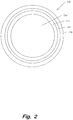
- Fig. 2 is a cross sectional diagram of an example of a blanket cylinder including an ITM in accordance with an example of the invention.
- the blanket cylinder (120) includes a base (150), for example a metal cylinder.
- the ITM comprises a rubber layer (152) disposed on the base (150), a primer layer (154) disposed on the rubber layer (152), and a silicone release layer (156) disposed on the primer layer (154).
- the rubber layer is referred to as a substrate (152).
- the rubber layer (152) may comprise an acrylic rubber comprising a blend of an acrylic resin Hi-Temp 4051 EP (Zeon Europe GmbH, Niederkasseler Lohweg 177, 40547 Düsseldorf, Germany) filled with carbon black pearls 130 (Cabot, Two Seaport Lane, Suite 1300, Boston, MA 02210, USA) and a curing system, which may comprise, for example, NPC-50 accelerator (ammonium derivative from Zeon).
- Hi-Temp 4051 EP Zeon Europe GmbH, Niederkasseler Lohweg 177, 40547 Düsseldorf, Germany
- carbon black pearls 130 Cabot, Two Seaport Lane, Suite 1300, Boston, MA 02210, USA
- NPC-50 accelerator ammonium derivative from Zeon
- Any suitable rubber can be used for the rubber layer 152, including but not limited to any of nitrile rubber (NBR), hydrogenated nitrile rubber (HNBR), polyurethane elastomer (PU), fluorocarbon elastomer, and fluorosilicone.
- NBR nitrile rubber
- HNBR hydrogenated nitrile rubber
- PU polyurethane elastomer
- fluorocarbon elastomer fluorosilicone
- the method is suitable for, but not limited to an ITM for a digital offset printing system.
- the method of the present invention may be for providing a silicone release layer on a different substrate, which is not for an ITM. Following the illustrative example, specific examples are described.
- a first primer which is curable, is provided on the substrate, for example the outer surface of an acrylic rubber layer.
- the first primer may be applied using a rod coating process.
- the first primer comprises an organosilane and a first catalyst comprising titanium, for example an organic titanate or a titanium chelate.
- the organosilane is an epoxysilane, for example 3-glycidoxypropyl trimethoxysilane (available from ABCR GmbH & Co. KG, Im Schlehert 10 D-76187, Düsseldorf, Germany, product code SIG5840) and the first catalyst is for example Tyzor ® AA75 (available from DuPont, 1007 Market St., Wilmington, Delaware, USA).
- the first primer is curable by a condensation reaction.
- a second primer which is curable, is also provided on the substrate.
- a rod coating process may be used.
- the second primer comprises an organosilane and a second catalyst.
- the second catalyst is different from the first catalyst and comprises platinum, and is for example a Karstedt catalyst with for example 9% platinum in solution (available from Johnson Matthey, 5th Floor, 25 Farringdon Street, London EC4A 4AB, United Kingdom) or SIP6831.2 catalyst (available from Gelest, 11 East Steel Road, Morrisville, PA 19067, USA).
- the organosilane is a vinyl silane, for example vinyltriethoxysilane (VTEO, available from Evonik, Kirschenallee, Darmstadt, 64293, Germany), vinyltriethoxysilane, an allyl silane or an unsaturated silane.
- the second primer may comprise a further organosilane, for example an epoxysilane such as 3-glycidoxypropyl trimethoxysilane (available from ABCR GmbH & Co. KG).
- the second primer is curable by an addition reaction, and is therefore cured by a different mechanism from the first primer.
- the second primer is provided on the first primer already applied to the substrate. Therefore, the second primer is supported by the substrate, and is considered to be on the substrate despite not adjoining the substrate.
- the second primer may be applied directly onto the substrate and the first primer may then be applied on the second primer; in that case the first primer is on the substrate but does not adjoin the substrate.
- the first primer and the second primer may be mixed together and then applied as a mixture of the first and second primers to the substrate. The substrate is uncured when the first and second primers are provided thereon.
- a silicone release formulation is provided on the first and second primers.
- a rod coating process may be used.
- the substrate may be uncured at this time.
- the first and second primers after being provided on the substrate may be at least partly absorbed in the uncured substrate material.
- the silicone release formulation is provided for example with a layer thickness of from 1.5 to 12 micrometres.
- the silicone release formulation comprises a vinyl silicone oil and a silicon hydride crosslinker.
- the silicone release layer may also comprise at least one of: a catalyst comprising platinum, for example a Karstedt type catalyst or a Pt(O) complex with vinylsiloxane ligands; an inhibitor, for example an acetylenic alcohol, tetramethyltetravinylcyclotetrasiloxane or tetramethyldivinyldisiloxane; and a filler, for example amorphous silica or carbon black.
- a catalyst comprising platinum, for example a Karstedt type catalyst or a Pt(O) complex with vinylsiloxane ligands
- an inhibitor for example an acetylenic alcohol, tetramethyltetravinylcyclotetrasiloxane or tetramethyldivinyldisiloxane
- a filler for example amorphous silica or carbon black.
- the silicone release layer comprises a vinyl-terminated polydimethyl siloxane, for example Polymer VS 500 having a viscosity at 25°C of 500 mPa ⁇ S, and a vinyl content of 0.14 mmol/g (available from Hanse Chemie, Charlottenburger Straße 9, 21502 Geesthacht, Germany); a vinyl-terminated with in-chain vinyl functionality polydimethyl siloxane, for example Polymer XPRV 5000 having a viscosity at 25°C of 3000 mPa ⁇ S, and a vinyl content of 0.4 mmol/g (available from Hanse Chemie); a silicone polymer containing silicon-hydride groups, for example Crosslinker 210 with a SiH content of 4.2 mmol/g (available from Hanse Chemie); a divinyl tetramethyl disiloxane-platinum(0) complex, for example Catalyst 510 (available from Hanse Chemie); and an alkinol, for example Polymer VS 500 having
- the first primer, the second primer and the silicone release formulation are cured.
- the curing may be performed simultaneously, for example by leaving the substrate with the applied first primer, second primer and silicone release formulation for 15 minutes at Room Temperature, followed by curing for 1 hour at 120°C.
- the curing for 1 hour at 120°C cures the substrate material, for example the acrylic rubber.
- the substrate (152) has thereby been provided with the silicone release layer (156), adhered by the primer layer (154) comprising a first primer material which is the cured first primer and a second primer material which is the cured second primer.
- the first primer material comprises titanium and the second primer material comprises platinum as a consequence of the first and second catalysts in the first and second primers.
- the method of providing the silicone release layer of the invention is advantageous.
- the resulting silicone release layer has excellent adhesion to the underlying substrate.
- the method of the invention reduces or stops inhibition of curing of the silicone release formulation, by limiting or preventing catalyst poisoning compounds from the body or substrate of the blanket cylinder from reaching the second primer catalyst, which could otherwise limit or stop curing of the silicone release formulation.
- the consequent providing of the first and then second primers provides the excellent adhesion and forms a barrier against the poisonous inhibitors.
- the combination of using different first and second catalysts and/or a different curing reaction in the first and second primers is believed to contribute to the excellent adhesion and inhibition reduction properties.
- the effectiveness of the barrier to reduce inhibition may be controlled. Furthermore, by curing the first primer, the second primer and the silicone release formulation in one method step, a more efficient method of providing a silicone release layer on a substrate is provided, compared with prior art techniques requiring curing or drying of a primer before applying a silicone relase layer.
- the primer (P17 see table 1.1 below) was coated on an uncured acrylic layer substrate.
- the first primer and the second primer are mixed together for applying to the substrate.
- An addition cure silicone release formulation (RL26 see table 1.2 below) was then coated on the applied primer mixture.
- the applied primer and silicone release formulation can be left for 15 minutes at Room Temperature (RT) to allow the condensation cure to start.
- RT Room Temperature
- the resulting ITM was then fully cured for 1 hour at 120°C.
- the adhesion of the silicone release layer on the substrate was then tested with a wet abrasion test, involving soaking the ITM in isopar for 1 minute at RT and then abrading with a cloth. A score of 4/4 was obtained, marked using the scale from 1 to 4 below.
- the first and second primers are applied separately on the acrylic rubber substrate.
- the first primer is a condensation cure system that contains a titanium condensation cure catalyst (Tyzor AA75); see table 3.1.
- the second primer is applied afterwards and uses a platinum catalyst for an addition cure system; see table 3.2.
- An addition cure silicone release formulation (see table 3.3) was then coated afterwards.
- the blanket was then fully cured for 1 hour at 120°C.
- the adhesion of the silicone release layer on the substrate was tested with the wet abrasion test, achieving a score of 4/4.
- silicone release formulation of example 3 has a very long pot life (several days), allowing it to be stored separately and reused easily.
- Table 3.1 Primer 1 supplier Wt% 3Glycidoxypropyltrimethoxysilane ABCR (SIG 5840) 82 Tyzor AA75 Dupont 18
- Table 3.2 Primer 2 supplier Wt% 3Glycidoxypropyltrimethoxysilane ABCR (SIG 5840) 73 Vinyltrimethoxysilane (VTMO) Evonik 23 Karstedt Catalyst (9% Platinum) Johnson Matthey 4
Landscapes
- Chemical & Material Sciences (AREA)
- Medicinal Chemistry (AREA)
- Health & Medical Sciences (AREA)
- Chemical Kinetics & Catalysis (AREA)
- Polymers & Plastics (AREA)
- Organic Chemistry (AREA)
- Physics & Mathematics (AREA)
- General Physics & Mathematics (AREA)
- Wood Science & Technology (AREA)
- Engineering & Computer Science (AREA)
- Life Sciences & Earth Sciences (AREA)
- Printing Plates And Materials Therefor (AREA)
- Laminated Bodies (AREA)
Description
- The HP Indigo line of digital printing presses is based on digital offset color technology, which combines ink-on-paper quality with multicolor printing on a wide range of paper, foil and plastic substrates. These digital printing presses offer cost-effective short-run printing, on-demand service and on-the-fly color switching.
- A digital offset printing system works by using digitally controlled lasers to create a latent image in the charged surface of a photo imaging plate (PIP). The lasers are controlled according to digital instructions from a digital image file. Digital instructions typically include one or more of the following parameters: image color, image spacing, image intensity, order of the color layers, etc. Special ink is then applied to the partially-charged surface of the PIP, recreating the desired image. The image is then transferred from the PIP to a heated blanket cylinder, and from the blanket cylinder to the desired substrate, which is placed into contact with the blanket cylinder by means of an impression cylinder. The ink is fluid on the heated blanket. Because of its role in transferring an image from the PIP to the ultimate substrate, the blanket may sometimes be referred to as an "intermediate transfer member" (ITM).
- A detailed description of the operation of a typical digital offset printer is described in Hewlett-Packard (HP) White Paper Publication, "Digital Offset Color vs. Xerography and Lithography", for example. Specifically, an example of a digital printer that can be used to create the disclosed printed articles is HP's digital printing press Indigo Press.TM. 1000, 2000, 4000, or newer, presses, manufactured by and commercially available from Hewlett-Packard Company of Palo Alto, California, USA.
- In order to apply pressure evenly in the course of transferring the ink and to accommodate slight variations in the surface of the substrate, the blanket is typically formed from a resilient material, such as synthetic rubber. Silicone is usually preferred, however, for the outermost layer of the blanket, because of its exceptional ink release properties. Such a silicone layer is an example of a release layer known in the art.
- Patent document
EP 0 776 928 A1 discloses an intermediate transfer member comprising a silicone resin release layer to be used as thermal transfer printing donor comprising a substrate layer, a primer layer containing at least one ethylenically unsaturated group, and a silicone resin coating layer on the surface of the primer layer. - Patent document
EP 0 781 823 A1 discloses a primer composition comprising: an organosilicon compound or mild hydrolyzates of the organosilicon, a platinum compound and an organic titanic acid ester. - It is difficult to apply a silicone release layer on a rubber underlayer, however, because the desirable release properties of silicone and the properties of rubber also make it difficult to form chemical bonds at their respective surfaces. Known methods include applying a primer layer on the rubber, waiting for the primer to dry, or curing the primer, before then applying the silicone release layer. This is time-consuming and not an efficient method of manufacture.
- The international patent application
WO 2008/073788 A1 discloses a method for producing an intermediate transfer member for digital offset printing comprising the coating the rubber layer on a body portion with a primer comprising an organosilane, a photoinitiator, and a catalyst, coating the primer with a release condensation type silicone and applying UV radiation at the end of the coating processes, after the silicone release layer has been applied. The primer composition comprises an epoxy silane and 3-methacryloxypropyltrimethoxysilane in the presence of an acetylacetonate titanate chelate as a catalyst and a photoinitiator. - Moreover, when forming a silicone release layer using for example a platinum catalyst in an addition-cure reaction, compounds from the underlying rubber layer or the body of the blanket cylinder under the blanket can inhibit or stop the curing reaction, by poisoning the catalyst. This is detrimental to the quality of the resulting silicone release layer.
- The international patent application
WO 2008/013521 A1 discloses an intermediate transfer member comprising an acrylic rubber layer, a primer layer disposed on the acrylic layer which includes an epoxyalkylalkoxysilane, an alkenylsilane and a titanium catalyst, and an addition cure RTV silicone layer disposed on the rubber layer. Such primer ensures a sufficient anchorage between the acrylic substrate and the cure silicone layer and at the same time acts as a barrier to the poisoning species on the surface of the acrylic rubber layer. - The accompanying drawing illustrates an example of the principles described herein and are a part of the specification. The illustrated example is merely an example and does not limit the scope of the claims.
-
Fig.1 is a diagram of an illustrative digital offset printing system; and -
Fig. 2 is a cross sectional diagram of an example of an intermediate transfer member in accordance with an example of the invention. - In the following description, for purposes of explanation, numerous specific details are set forth in order to provide a thorough understanding of the present systems and methods. It will be apparent, however, to one skilled in the art that the present apparatus, systems and methods may be practiced without these specific details. Reference in the specification to "an example" or similar language means that a particular feature, structure, or characteristic described in connection with the example is included in at least that one example, but not necessarily in other examples.
- The present invention provides a method of forming a silicone release layer (156) on a substrate (152), for an intermediate transfer member of a digital offset printing system, the method including: a) providing a curable first primer on the substrate; b) providing a curable second primer on the substrate; c) providing a curable silicone release formulation on the curable first and second primers; and then d) curing the first primer, the second primer and the release formulation; characterised in that the first primer comprises an organosilane and a first catalyst, which comprises titanium; the second primer comprises an organosilane and a second catalyst, which comprises platinum; the substrate is a rubber layer; and the first primer is curable by a condensation reaction and the second primer is curable by an addition reaction.
- Furthermore the present invention discloses an intermediate transfer member for a digital offset printing system obtainable by the method of the present invention, comprising a substrate (152), a primer layer (154) on the substrate, the primer layer comprising a cured first primer material and a cured second primer material, and a cured silicone release layer (156) on the primer layer, characterised in that the first primer material comprises titanium and an organosilane; the second primer material comprises platinum and an organosilane; the substrate comprises a rubber layer; and the first primer has been cured by a condensation reaction and the second primer has been cured by an addition reaction.
- An example of such a digital offset printing system will first be described.
-
Fig. 1 is a diagram of an illustrative digital offset printing system (100), which in this example is a digital Liquid Electro Photographic (LEP) printing system. The term "Liquid Electro Photographic" or "LEP" refers to a process of printing in which a liquid toner is applied onto a surface having a pattern of electrostatic charge, to form a pattern of liquid toner corresponding with the electrostatic charge pattern. This pattern of liquid toner is then transferred to at least one intermediate surface, and then to a print medium. During the operation of a digital LEP system, ink images are formed on the surface of a photo-imaging cylinder. These ink images are transferred to a heated blanket cylinder and then to a print medium. The photo-imaging cylinder continues to rotate, passing through various stations to form the next image. - In the illustrative digital LEP system (100), the desired image is communicated to the printing system (100) in digital form. The desired image may include any combination of text, graphics and images. The desired image is initially formed on the photo-imaging cylinder (105), transferred to a blanket (122) on the outside of the blanket cylinder (120), and then transferred to the print medium (140). The blanket (122) may otherwise be referred to as an intermediate transfer member (ITM).
- According to one illustrative example, an image is formed on the photo-imaging cylinder (105) by rotating a clean, bare segment of the photo-imaging cylinder (105) under the photo charging unit (110). The photo charging unit (110) includes a charging device such as corona wire, charge roller, or other charging device and a laser imaging portion. A uniform static charge is deposited on the photo-imaging cylinder (105) by the photo charging unit (110). As the photo-imaging cylinder (105) continues to rotate, it passes the laser imaging portion of the photo charging unit (110) that dissipates the static charges in selected portions of the image area to leave an invisible electrostatic charge pattern that represents the image to be printed.
- Ink is transferred onto the photo-imaging cylinder (105) by Binary Ink Developer (BID) units (115). There is one BID unit (115) for each ink color. During printing, the appropriate BID unit is engaged with the photo-imaging cylinder (105). The engaged BID unit presents a uniform film of ink to the photo-imaging cylinder (105). The ink contains electrically charged pigment particles which are attracted to the opposing electrical fields on the image areas of the photo-imaging cylinder (105). The ink is repelled from the uncharged, non-image areas. The photo-imaging cylinder (105) now has a single color ink image on its surface.
- The photo-imaging cylinder (105) continues to rotate and transfers the ink image to the ITM (122) of the blanket cylinder (120) which is heatable. The blanket cylinder transfers the image from the ITM to a sheet of media wrapped around the impression cylinder (130). As will be further described below, this process may be repeated for each of the colored ink layers to be included in the final image.
- The print medium (140) enters the printing system (100) from the right, passes over a feed tray (125), and is wrapped onto the impression cylinder (130). As the print medium (140) contacts the ITM (122) of the blanket cylinder (120), the single color ink image is transferred to the print medium (140). The creation, transfer, and cleaning of the photo-imaging cylinder (105) is a continuous process, with hundreds of images being created and transferred per minute.
- To form a single color image (such as a black and white image), one pass of the print medium (140) through the impression cylinder (130) and the blanket cylinder (120) completes the desired image. For a color image, the print medium (140) is retained on the impression cylinder (130) and makes multiple contacts with the blanket cylinder (120) as it passes through the nip (127). At each contact, an additional color plane may be placed on the print medium (140). The term nip refers to a region between two rollers where the rollers are in closest proximity. When a media sheet or other material passes through the nip, the distance between the two rollers can be adjusted to produce pressure on the media.
- For example, to generate a four color image, the photo charging unit (110) forms a second pattern on the photo-imaging cylinder (105) which receives the second ink color from a second BID unit (115). As described above, this second ink pattern is transferred to the ITM (122) and impressed onto the print medium (140) as it continues to rotate with the impression cylinder (130). This continues until the desired image with all four color planes is formed on the print medium. Following the complete formation of the desired image on the print medium (140), the print medium (140) can exit the machine or be duplexed to create a second image on the opposite surface of the print medium (140). Because the printing system is digital, the operator can change the image being printed at any time and without manual reconfiguration.
-
Fig. 2 is a cross sectional diagram of an example of a blanket cylinder including an ITM in accordance with an example of the invention. The blanket cylinder (120) includes a base (150), for example a metal cylinder. The ITM comprises a rubber layer (152) disposed on the base (150), a primer layer (154) disposed on the rubber layer (152), and a silicone release layer (156) disposed on the primer layer (154). The rubber layer is referred to as a substrate (152). In some examples, the rubber layer (152) may comprise an acrylic rubber comprising a blend of an acrylic resin Hi-Temp 4051 EP (Zeon Europe GmbH, Niederkasseler Lohweg 177, 40547 Düsseldorf, Germany) filled with carbon black pearls 130 (Cabot, Two Seaport Lane, Suite 1300, Boston, MA 02210, USA) and a curing system, which may comprise, for example, NPC-50 accelerator (ammonium derivative from Zeon). The acrylic rubber is at least partly cured. - Any suitable rubber can be used for the
rubber layer 152, including but not limited to any of nitrile rubber (NBR), hydrogenated nitrile rubber (HNBR), polyurethane elastomer (PU), fluorocarbon elastomer, and fluorosilicone. - An illustrative example of a method of providing the silicone release layer on the substrate will now be described. The method is suitable for, but not limited to an ITM for a digital offset printing system. For example, the method of the present invention may be for providing a silicone release layer on a different substrate, which is not for an ITM. Following the illustrative example, specific examples are described.
- A first primer, which is curable, is provided on the substrate, for example the outer surface of an acrylic rubber layer. The first primer may be applied using a rod coating process. The first primer comprises an organosilane and a first catalyst comprising titanium, for example an organic titanate or a titanium chelate. In an illustrative example the organosilane is an epoxysilane, for example 3-glycidoxypropyl trimethoxysilane (available from ABCR GmbH & Co. KG, Im Schlehert 10 D-76187, Karlsruhe, Germany, product code SIG5840) and the first catalyst is for example Tyzor® AA75 (available from DuPont, 1007 Market St., Wilmington, Delaware, USA). The first primer is curable by a condensation reaction.
- A second primer, which is curable, is also provided on the substrate. A rod coating process may be used. The second primer comprises an organosilane and a second catalyst. The second catalyst is different from the first catalyst and comprises platinum, and is for example a Karstedt catalyst with for example 9% platinum in solution (available from Johnson Matthey, 5th Floor, 25 Farringdon Street, London EC4A 4AB, United Kingdom) or SIP6831.2 catalyst (available from Gelest, 11 East Steel Road, Morrisville, PA 19067, USA). In an illustrative example the organosilane is a vinyl silane, for example vinyltriethoxysilane (VTEO, available from Evonik, Kirschenallee, Darmstadt, 64293, Germany), vinyltriethoxysilane, an allyl silane or an unsaturated silane. In some examples the second primer may comprise a further organosilane, for example an epoxysilane such as 3-glycidoxypropyl trimethoxysilane (available from ABCR GmbH & Co. KG). The second primer is curable by an addition reaction, and is therefore cured by a different mechanism from the first primer.
- In this example, the second primer is provided on the first primer already applied to the substrate. Therefore, the second primer is supported by the substrate, and is considered to be on the substrate despite not adjoining the substrate. In other examples, the second primer may be applied directly onto the substrate and the first primer may then be applied on the second primer; in that case the first primer is on the substrate but does not adjoin the substrate. In other examples, the first primer and the second primer may be mixed together and then applied as a mixture of the first and second primers to the substrate. The substrate is uncured when the first and second primers are provided thereon.
- A silicone release formulation is provided on the first and second primers. A rod coating process may be used. The substrate may be uncured at this time. The first and second primers after being provided on the substrate may be at least partly absorbed in the uncured substrate material. The silicone release formulation is provided for example with a layer thickness of from 1.5 to 12 micrometres. In this example the silicone release formulation comprises a vinyl silicone oil and a silicon hydride crosslinker. The silicone release layer may also comprise at least one of: a catalyst comprising platinum, for example a Karstedt type catalyst or a Pt(O) complex with vinylsiloxane ligands; an inhibitor, for example an acetylenic alcohol, tetramethyltetravinylcyclotetrasiloxane or tetramethyldivinyldisiloxane; and a filler, for example amorphous silica or carbon black. In an illustrative example the silicone release layer comprises a vinyl-terminated polydimethyl siloxane, for example Polymer VS 500 having a viscosity at 25°C of 500 mPa·S, and a vinyl content of 0.14 mmol/g (available from Hanse Chemie, Charlottenburger Straße 9, 21502 Geesthacht, Germany); a vinyl-terminated with in-chain vinyl functionality polydimethyl siloxane, for example Polymer XPRV 5000 having a viscosity at 25°C of 3000 mPa·S, and a vinyl content of 0.4 mmol/g (available from Hanse Chemie); a silicone polymer containing silicon-hydride groups, for example Crosslinker 210 with a SiH content of 4.2 mmol/g (available from Hanse Chemie); a divinyl tetramethyl disiloxane-platinum(0) complex, for example Catalyst 510 (available from Hanse Chemie); and an alkinol, for example Inhibitor 600 (available from Hanse Chemie). The silicone release formulation is for example curable by an addition reaction.
- After providing the silicone release formulation, the first primer, the second primer and the silicone release formulation are cured. The curing may be performed simultaneously, for example by leaving the substrate with the applied first primer, second primer and silicone release formulation for 15 minutes at Room Temperature, followed by curing for 1 hour at 120°C. The curing for 1 hour at 120°C cures the substrate material, for example the acrylic rubber.
- After curing, the substrate (152) has thereby been provided with the silicone release layer (156), adhered by the primer layer (154) comprising a first primer material which is the cured first primer and a second primer material which is the cured second primer. The first primer material comprises titanium and the second primer material comprises platinum as a consequence of the first and second catalysts in the first and second primers.
- The method of providing the silicone release layer of the invention is advantageous. The resulting silicone release layer has excellent adhesion to the underlying substrate. Moreover, the method of the invention reduces or stops inhibition of curing of the silicone release formulation, by limiting or preventing catalyst poisoning compounds from the body or substrate of the blanket cylinder from reaching the second primer catalyst, which could otherwise limit or stop curing of the silicone release formulation. Without being limited to any theory, it is believed that the consequent providing of the first and then second primers provides the excellent adhesion and forms a barrier against the poisonous inhibitors. The combination of using different first and second catalysts and/or a different curing reaction in the first and second primers is believed to contribute to the excellent adhesion and inhibition reduction properties. It is envisaged that, by changing the amount of catalyst in the first or second primer, the effectiveness of the barrier to reduce inhibition may be controlled. Furthermore, by curing the first primer, the second primer and the silicone release formulation in one method step, a more efficient method of providing a silicone release layer on a substrate is provided, compared with prior art techniques requiring curing or drying of a primer before applying a silicone relase layer.
- Specific examples of the method of providing a silicone release layer according to the invention will now be described.
- Using a rod coating process, the primer (P17 see table 1.1 below) was coated on an uncured acrylic layer substrate. In this example the first primer and the second primer are mixed together for applying to the substrate. An addition cure silicone release formulation (RL26 see table 1.2 below) was then coated on the applied primer mixture.
Table 1.1 Primer (P17) Supplier Wt% 3Glycidoxypropyl) trimethoxysilane (SIG 5840) ABCR 50 Vinyltriethoxysilane (VTEO) Evonik 35 Tyzor AA75 Dupont 10 SIP6831.2 (Platinum Catalyst) Gelest 5 Table 1.2 Release (RL26) Supplier Wt% Polymer VS 500 Hanse Chemie 69.3 Polymer XPRV 5000 Hanse Chemie 17.3 Crosslinker 210 Hanse Chemie 8.7 Catalyst 510 Hanse Chemie 0.4 Inhibitor 600 Hanse Chemie 4.3 - The applied primer and silicone release formulation can be left for 15 minutes at Room Temperature (RT) to allow the condensation cure to start. The resulting ITM was then fully cured for 1 hour at 120°C.
- The adhesion of the silicone release layer on the substrate was then tested with a wet abrasion test, involving soaking the ITM in isopar for 1 minute at RT and then abrading with a cloth. A score of 4/4 was obtained, marked using the scale from 1 to 4 below.
- Scores for wet abrasion test:
- 1 Easy - Release is easily removed without any effort;
- 2 Medium - the silicone release layer is removed under small effort;
- 3 Good - the silicone release layer is removed after a great effort; and
- 4 Excellent - the silicone release layer cannot be removed.
- The same primer and method was used as in Example 1, but using another platinum catalyst from Johnson Matthey; see Table 2. Excellent adhesion of the silicone release layer on the acrylic substrate was obtained, scoring 4/4.
Table 2 Primer supplier Wt% 3Glycidoxypropyl) ABCR trimethoxysilane (SIG 5840) 54 Vinyltriethoxysilane (VTEO) Evonik 35 Tyzor AA75 Dupont 10 Karstedt Catalyst (9% Platinum)) Johnson Matthey 1 - In this example the first and second primers are applied separately on the acrylic rubber substrate. The first primer is a condensation cure system that contains a titanium condensation cure catalyst (Tyzor AA75); see table 3.1. The second primer is applied afterwards and uses a platinum catalyst for an addition cure system; see table 3.2. An addition cure silicone release formulation (see table 3.3) was then coated afterwards.
- The blanket was then fully cured for 1 hour at 120°C. The adhesion of the silicone release layer on the substrate was tested with the wet abrasion test, achieving a score of 4/4.
- An advantage of the silicone release formulation of example 3 is that it has a very long pot life (several days), allowing it to be stored separately and reused easily.
Table 3.1 Primer 1 supplier Wt% 3Glycidoxypropyltrimethoxysilane ABCR (SIG 5840) 82 Tyzor AA75 Dupont 18 Table 3.2 Primer 2 supplier Wt% 3Glycidoxypropyltrimethoxysilane ABCR (SIG 5840) 73 Vinyltrimethoxysilane (VTMO) Evonik 23 Karstedt Catalyst (9% Platinum) Johnson Matthey 4 Table 3.3 Release supplier Wt% Polymer VS 2000 Hanse Chemie 93.5 Crosslinker 101 Hanse Chemie 4.7 Inhibitor 600 Hanse Chemie 1.8 - The preceding description has been presented only to illustrate and describe examples of the principles described. This description is not intended to be exhaustive or to limit these principles to any precise form disclosed. Many modifications and variations are possible in light of the above teaching.
Claims (11)
- A method of forming a silicone release layer (156) on a substrate (152), for an intermediate transfer member of a digital offset printing system, the method including:a) providing a curable first primer on the substrate;b) providing a curable second primer on the substrate;c) providing a curable silicone release formulation on the curable first and second primers; and thend) curing the first primer, the second primer and the release formulation;characterised in that
the first primer comprises an organosilane and a first catalyst, which comprises titanium;
the second primer comprises an organosilane and a second catalyst which comprises platinum;
the substrate is a rubber layer; and
the first primer is curable by a condensation reaction and the second primer is curable by an addition reaction. - A method according to claim 1, wherein the first primer comprises an epoxysilane, and the first catalyst comprises an organic titanate or a titanium chelate.
- A method according to claim 1, wherein the second primer comprises at least one of a vinyl silane, an allyl silane and an unsaturated silane, and the second catalyst comprises a Karstedt catalyst.
- A method according to claim 1, wherein the silicone release formulation comprises at least one of a vinyl silicone oil, a silicon hydride crosslinker, a Karstedt catalyst, a catalyst comprising a Pt(0) complex with vinylsiloxane ligands, an inhibitor, an acetylenic alcohol, tetramethyltetravinylcyclotetrasiloxane, tetramethyldivinyldisiloxane, a filler, amorphous silica, carbon black, a vinyl-terminated polydimethyl siloxane, a vinyl silicone, a divinyl tetramethyl disiloxane-platinum(0) complex, and an alkinol.
- A method according to claim 1, wherein the silicone release formulation is curable by an addition reaction using a catalyst comprising platinum.
- A method according to claim 1, wherein in steps a), b) and c) the substrate comprises an uncured acrylic rubber which is cured after performing steps a), b) and c).
- A method according to claim 1, wherein the curable first primer and the curable second primer are provided in steps a) and b) together as a mixture of the curable first and second primers.
- An intermediate transfer member for a digital offset printing system, comprising a substrate (152), a primer layer (154) on the substrate, the primer layer comprising a cured first primer material and a cured second primer material, and a cured silicone release layer (156) on the primer layer,
characterised in that:the first primer material comprises titanium and an organosilane;the second primer material comprises platinum and an organosilane;the substrate comprises a rubber layer; andthe first primer has been cured by a condensation reaction and the second primer has been cured by an addition reaction,wherein the intermediate transfer member is obtainable by the method of claim 1. - An intermediate transfer member according to claim 8, wherein the first primer material comprises an epoxysilane cured with a first catalyst comprising an organic titanate or a titanium chelate, and the second primer material comprises at least one of a vinyl silane, an allyl silane and an unsaturated silane cured with a second catalyst comprising a Karstedt catalyst.
- An intermediate transfer member according to claim 9, wherein the substrate comprises an acrylic rubber.
- A digital offset printing system comprising an intermediate transfer member in accordance with claim 9.
Applications Claiming Priority (1)
| Application Number | Priority Date | Filing Date | Title |
|---|---|---|---|
| PCT/EP2011/068918 WO2013060377A1 (en) | 2011-10-27 | 2011-10-27 | Method of forming a release layer |
Publications (2)
| Publication Number | Publication Date |
|---|---|
| EP2771391A1 EP2771391A1 (en) | 2014-09-03 |
| EP2771391B1 true EP2771391B1 (en) | 2017-01-11 |
Family
ID=44925508
Family Applications (1)
| Application Number | Title | Priority Date | Filing Date |
|---|---|---|---|
| EP11781473.1A Not-in-force EP2771391B1 (en) | 2011-10-27 | 2011-10-27 | Method of forming a release layer |
Country Status (3)
| Country | Link |
|---|---|
| US (1) | US9333534B2 (en) |
| EP (1) | EP2771391B1 (en) |
| WO (1) | WO2013060377A1 (en) |
Cited By (1)
| Publication number | Priority date | Publication date | Assignee | Title |
|---|---|---|---|---|
| WO2021141589A1 (en) * | 2020-01-09 | 2021-07-15 | Hewlett-Packard Development Company, L.P. | Methods for forming structured images and related aspects |
Families Citing this family (41)
| Publication number | Priority date | Publication date | Assignee | Title |
|---|---|---|---|---|
| US10632740B2 (en) | 2010-04-23 | 2020-04-28 | Landa Corporation Ltd. | Digital printing process |
| US10569534B2 (en) | 2012-03-05 | 2020-02-25 | Landa Corporation Ltd. | Digital printing system |
| DE202013012736U1 (en) | 2012-03-05 | 2018-12-20 | Landa Corporation Ltd. | Ink film constructions |
| US10642198B2 (en) | 2012-03-05 | 2020-05-05 | Landa Corporation Ltd. | Intermediate transfer members for use with indirect printing systems and protonatable intermediate transfer members for use with indirect printing systems |
| US9498946B2 (en) | 2012-03-05 | 2016-11-22 | Landa Corporation Ltd. | Apparatus and method for control or monitoring of a printing system |
| US10190012B2 (en) | 2012-03-05 | 2019-01-29 | Landa Corporation Ltd. | Treatment of release layer and inkjet ink formulations |
| US9902147B2 (en) | 2012-03-05 | 2018-02-27 | Landa Corporation Ltd. | Digital printing system |
| US9643403B2 (en) | 2012-03-05 | 2017-05-09 | Landa Corporation Ltd. | Printing system |
| BR112014021786B1 (en) | 2012-03-05 | 2021-06-08 | Landa Corporation Ltd | paint film structures |
| EP2822778B1 (en) | 2012-03-05 | 2019-05-08 | Landa Corporation Ltd. | Digital printing process |
| US10434761B2 (en) | 2012-03-05 | 2019-10-08 | Landa Corporation Ltd. | Digital printing process |
| US9517618B2 (en) | 2012-03-15 | 2016-12-13 | Landa Corporation Ltd. | Endless flexible belt for a printing system |
| JP6066906B2 (en) * | 2012-03-29 | 2017-01-25 | キヤノン株式会社 | Electrophotographic member manufacturing method and coating solution |
| WO2015036864A1 (en) | 2013-09-11 | 2015-03-19 | Landa Corporation Ltd. | Treatment of release layer |
| GB201401173D0 (en) | 2013-09-11 | 2014-03-12 | Landa Corp Ltd | Ink formulations and film constructions thereof |
| US10295935B2 (en) | 2014-10-31 | 2019-05-21 | Hp Indigo B.V. | Electrostatic printing apparatus and intermediate transfer members |
| US20170329261A1 (en) * | 2014-10-31 | 2017-11-16 | Hewlett-Packard Indigo B.V. | Electrostatic printing apparatus and intermediate transfer members |
| JP6519201B2 (en) * | 2015-01-27 | 2019-05-29 | 富士ゼロックス株式会社 | Cylindrical member, cylindrical member unit, and image forming apparatus |
| GB2536489B (en) | 2015-03-20 | 2018-08-29 | Landa Corporation Ltd | Indirect printing system |
| GB2537813A (en) | 2015-04-14 | 2016-11-02 | Landa Corp Ltd | Apparatus for threading an intermediate transfer member of a printing system |
| CN108780292A (en) * | 2016-04-18 | 2018-11-09 | 惠普印迪戈股份公司 | Liquid electrophotographic printing equipment and intermediate transfer member |
| GB201609463D0 (en) | 2016-05-30 | 2016-07-13 | Landa Labs 2012 Ltd | Method of manufacturing a multi-layer article |
| DE112017002714T5 (en) | 2016-05-30 | 2019-02-28 | Landa Corporation Ltd. | Digital printing process |
| US10768553B2 (en) | 2017-04-18 | 2020-09-08 | Hp Indigo B.V. | Layers for resistance to adhesion of ink |
| CN111212736B (en) | 2017-10-19 | 2021-11-23 | 兰达公司 | Endless flexible belt for a printing system |
| WO2019097464A1 (en) | 2017-11-19 | 2019-05-23 | Landa Corporation Ltd. | Digital printing system |
| US11511536B2 (en) | 2017-11-27 | 2022-11-29 | Landa Corporation Ltd. | Calibration of runout error in a digital printing system |
| US11707943B2 (en) | 2017-12-06 | 2023-07-25 | Landa Corporation Ltd. | Method and apparatus for digital printing |
| US11679615B2 (en) | 2017-12-07 | 2023-06-20 | Landa Corporation Ltd. | Digital printing process and method |
| EP3714333A4 (en) * | 2018-06-12 | 2021-02-24 | Hewlett-Packard Development Company, L.P. | INTERMEDIATE TRANSMISSION ELEMENT AND METHOD OF MANUFACTURING THEREOF |
| IL279556B2 (en) | 2018-06-26 | 2024-06-01 | Landa Corp Ltd | An intermediate transfer member for a digital printing system |
| US10994528B1 (en) | 2018-08-02 | 2021-05-04 | Landa Corporation Ltd. | Digital printing system with flexible intermediate transfer member |
| US12001902B2 (en) | 2018-08-13 | 2024-06-04 | Landa Corporation Ltd. | Correcting distortions in digital printing by implanting dummy pixels in a digital image |
| US11318734B2 (en) | 2018-10-08 | 2022-05-03 | Landa Corporation Ltd. | Friction reduction means for printing systems and method |
| CN113272144B (en) | 2018-12-24 | 2023-04-04 | 兰达公司 | Digital printing system and method |
| WO2020202145A1 (en) | 2019-03-31 | 2020-10-08 | Landa Corporation Ltd | Systems and methods for preventing or minimizing printing defects in printing processes |
| WO2021105806A1 (en) | 2019-11-25 | 2021-06-03 | Landa Corporation Ltd. | Drying ink in digital printing using infrared radiation absorbed by particles embedded inside itm |
| US11321028B2 (en) | 2019-12-11 | 2022-05-03 | Landa Corporation Ltd. | Correcting registration errors in digital printing |
| CN114868087A (en) | 2019-12-29 | 2022-08-05 | 兰达公司 | Printing method and system |
| CN112318893B (en) * | 2020-10-19 | 2022-06-28 | 广西北海跃达玻璃钢制品有限公司 | Preparation method of glass fiber reinforced plastic sand inclusion pipe |
| JP2024506561A (en) | 2021-02-02 | 2024-02-14 | ランダ コーポレイション リミテッド | Reduce distortion in printed images |
Citations (2)
| Publication number | Priority date | Publication date | Assignee | Title |
|---|---|---|---|---|
| EP0781823A1 (en) * | 1995-11-28 | 1997-07-02 | Dow Corning Toray Silicone Company, Limited | Primer composition and adhesion method |
| WO2012102412A1 (en) * | 2011-01-28 | 2012-08-02 | Dow Corning Toray Co., Ltd. | Primer composition and laminate |
Family Cites Families (9)
| Publication number | Priority date | Publication date | Assignee | Title |
|---|---|---|---|---|
| US5672428A (en) | 1995-10-17 | 1997-09-30 | Hoechst Celanese Corporation | Silicone release coated polyester film and a process for coating the film |
| GB9523764D0 (en) * | 1995-11-21 | 1996-01-24 | Ici Plc | Polymeric film |
| US6551716B1 (en) | 1997-06-03 | 2003-04-22 | Indigo N.V. | Intermediate transfer blanket and method of producing the same |
| KR100454563B1 (en) | 1999-08-09 | 2004-11-03 | 에스케이씨 주식회사 | Silicon-based coating composition and the polyester release film coated thereby |
| JP2002265922A (en) | 2001-03-08 | 2002-09-18 | Konishi Co Ltd | Automotive glass adhesive |
| US6838140B1 (en) | 2003-06-13 | 2005-01-04 | Xerox Corporation | Fuser member having platinum catalyzed addition cured silicone layer |
| DE10328843A1 (en) | 2003-06-26 | 2005-01-27 | Wacker-Chemie Gmbh | Primer for silicone rubber |
| US10072181B2 (en) | 2006-07-25 | 2018-09-11 | Hewlett-Packard Development Company, L.P. | Laser printer systems, intermediate transfer members, primer layers for intermediate transfer members, and primer layer compositions |
| US7754298B2 (en) * | 2006-12-11 | 2010-07-13 | Hewlett-Packard Development Company, L.P. | Intermediate transfer member and method for making same |
-
2011
- 2011-10-27 US US14/354,202 patent/US9333534B2/en active Active
- 2011-10-27 EP EP11781473.1A patent/EP2771391B1/en not_active Not-in-force
- 2011-10-27 WO PCT/EP2011/068918 patent/WO2013060377A1/en not_active Ceased
Patent Citations (3)
| Publication number | Priority date | Publication date | Assignee | Title |
|---|---|---|---|---|
| EP0781823A1 (en) * | 1995-11-28 | 1997-07-02 | Dow Corning Toray Silicone Company, Limited | Primer composition and adhesion method |
| WO2012102412A1 (en) * | 2011-01-28 | 2012-08-02 | Dow Corning Toray Co., Ltd. | Primer composition and laminate |
| JP2012158619A (en) * | 2011-01-28 | 2012-08-23 | Dow Corning Toray Co Ltd | Primer composition and laminate |
Cited By (1)
| Publication number | Priority date | Publication date | Assignee | Title |
|---|---|---|---|---|
| WO2021141589A1 (en) * | 2020-01-09 | 2021-07-15 | Hewlett-Packard Development Company, L.P. | Methods for forming structured images and related aspects |
Also Published As
| Publication number | Publication date |
|---|---|
| EP2771391A1 (en) | 2014-09-03 |
| US9333534B2 (en) | 2016-05-10 |
| CN104136510A (en) | 2014-11-05 |
| US20140369722A1 (en) | 2014-12-18 |
| WO2013060377A1 (en) | 2013-05-02 |
Similar Documents
| Publication | Publication Date | Title |
|---|---|---|
| US9333534B2 (en) | Method of forming a release layer | |
| US7754298B2 (en) | Intermediate transfer member and method for making same | |
| US8041275B2 (en) | Release layer | |
| EP2683556B1 (en) | Intermediate transfer members | |
| CN102555450A (en) | Coating apparatus and image forming apparatus | |
| CA2875529C (en) | Methods for ink-based digital printing with high ink transfer efficiency | |
| JP6470663B2 (en) | Image marking apparatus, image forming method on image receiving medium substrate, and image forming system | |
| US8931412B2 (en) | Method for printing of a recording | |
| CN102612672B (en) | Release layer of intermediate transfer member | |
| CN108780293A (en) | Releasing layer | |
| US20200125009A1 (en) | Intermediate transfer member and method of production thereof | |
| CN104136510B (en) | The method of forming the release layer | |
| US8764179B2 (en) | Methods for radiation curable gel ink leveling and direct-to-substrate digital radiation curable gel ink printing, apparatus and systems having pressure member with hydrophobic surface | |
| JP2019507911A (en) | Liquid electrophotographic printing apparatus and intermediate transfer member | |
| EP3241076B1 (en) | Release layer | |
| US20220050406A1 (en) | Method of refurbishing an intermediate transfer member | |
| US20230118543A1 (en) | Intermediate transfer member and method of production thereof | |
| JP2016150456A (en) | Recording device | |
| WO2014005655A1 (en) | Printing system | |
| JP2005189558A (en) | Developing roller or its manufacturing method |
Legal Events
| Date | Code | Title | Description |
|---|---|---|---|
| PUAI | Public reference made under article 153(3) epc to a published international application that has entered the european phase |
Free format text: ORIGINAL CODE: 0009012 |
|
| 17P | Request for examination filed |
Effective date: 20140430 |
|
| AK | Designated contracting states |
Kind code of ref document: A1 Designated state(s): AL AT BE BG CH CY CZ DE DK EE ES FI FR GB GR HR HU IE IS IT LI LT LU LV MC MK MT NL NO PL PT RO RS SE SI SK SM TR |
|
| DAX | Request for extension of the european patent (deleted) | ||
| 17Q | First examination report despatched |
Effective date: 20150317 |
|
| GRAP | Despatch of communication of intention to grant a patent |
Free format text: ORIGINAL CODE: EPIDOSNIGR1 |
|
| INTG | Intention to grant announced |
Effective date: 20160916 |
|
| GRAS | Grant fee paid |
Free format text: ORIGINAL CODE: EPIDOSNIGR3 |
|
| GRAA | (expected) grant |
Free format text: ORIGINAL CODE: 0009210 |
|
| RIN1 | Information on inventor provided before grant (corrected) |
Inventor name: SORIA, MEIR Inventor name: GUSLITZER, REGINA Inventor name: SLIVNIAK, RAIA Inventor name: RUDOY, YEVGENIA Inventor name: RAVIV, OSHRA |
|
| AK | Designated contracting states |
Kind code of ref document: B1 Designated state(s): AL AT BE BG CH CY CZ DE DK EE ES FI FR GB GR HR HU IE IS IT LI LT LU LV MC MK MT NL NO PL PT RO RS SE SI SK SM TR |
|
| REG | Reference to a national code |
Ref country code: GB Ref legal event code: FG4D |
|
| REG | Reference to a national code |
Ref country code: CH Ref legal event code: EP |
|
| REG | Reference to a national code |
Ref country code: AT Ref legal event code: REF Ref document number: 861221 Country of ref document: AT Kind code of ref document: T Effective date: 20170115 |
|
| REG | Reference to a national code |
Ref country code: IE Ref legal event code: FG4D |
|
| REG | Reference to a national code |
Ref country code: DE Ref legal event code: R096 Ref document number: 602011034301 Country of ref document: DE |
|
| REG | Reference to a national code |
Ref country code: LT Ref legal event code: MG4D |
|
| REG | Reference to a national code |
Ref country code: NL Ref legal event code: MP Effective date: 20170111 |
|
| REG | Reference to a national code |
Ref country code: AT Ref legal event code: MK05 Ref document number: 861221 Country of ref document: AT Kind code of ref document: T Effective date: 20170111 |
|
| PG25 | Lapsed in a contracting state [announced via postgrant information from national office to epo] |
Ref country code: NL Free format text: LAPSE BECAUSE OF FAILURE TO SUBMIT A TRANSLATION OF THE DESCRIPTION OR TO PAY THE FEE WITHIN THE PRESCRIBED TIME-LIMIT Effective date: 20170111 |
|
| PG25 | Lapsed in a contracting state [announced via postgrant information from national office to epo] |
Ref country code: IS Free format text: LAPSE BECAUSE OF FAILURE TO SUBMIT A TRANSLATION OF THE DESCRIPTION OR TO PAY THE FEE WITHIN THE PRESCRIBED TIME-LIMIT Effective date: 20170511 Ref country code: LT Free format text: LAPSE BECAUSE OF FAILURE TO SUBMIT A TRANSLATION OF THE DESCRIPTION OR TO PAY THE FEE WITHIN THE PRESCRIBED TIME-LIMIT Effective date: 20170111 Ref country code: FI Free format text: LAPSE BECAUSE OF FAILURE TO SUBMIT A TRANSLATION OF THE DESCRIPTION OR TO PAY THE FEE WITHIN THE PRESCRIBED TIME-LIMIT Effective date: 20170111 Ref country code: HR Free format text: LAPSE BECAUSE OF FAILURE TO SUBMIT A TRANSLATION OF THE DESCRIPTION OR TO PAY THE FEE WITHIN THE PRESCRIBED TIME-LIMIT Effective date: 20170111 Ref country code: GR Free format text: LAPSE BECAUSE OF FAILURE TO SUBMIT A TRANSLATION OF THE DESCRIPTION OR TO PAY THE FEE WITHIN THE PRESCRIBED TIME-LIMIT Effective date: 20170412 Ref country code: NO Free format text: LAPSE BECAUSE OF FAILURE TO SUBMIT A TRANSLATION OF THE DESCRIPTION OR TO PAY THE FEE WITHIN THE PRESCRIBED TIME-LIMIT Effective date: 20170411 |
|
| PG25 | Lapsed in a contracting state [announced via postgrant information from national office to epo] |
Ref country code: RS Free format text: LAPSE BECAUSE OF FAILURE TO SUBMIT A TRANSLATION OF THE DESCRIPTION OR TO PAY THE FEE WITHIN THE PRESCRIBED TIME-LIMIT Effective date: 20170111 Ref country code: AT Free format text: LAPSE BECAUSE OF FAILURE TO SUBMIT A TRANSLATION OF THE DESCRIPTION OR TO PAY THE FEE WITHIN THE PRESCRIBED TIME-LIMIT Effective date: 20170111 Ref country code: ES Free format text: LAPSE BECAUSE OF FAILURE TO SUBMIT A TRANSLATION OF THE DESCRIPTION OR TO PAY THE FEE WITHIN THE PRESCRIBED TIME-LIMIT Effective date: 20170111 Ref country code: SE Free format text: LAPSE BECAUSE OF FAILURE TO SUBMIT A TRANSLATION OF THE DESCRIPTION OR TO PAY THE FEE WITHIN THE PRESCRIBED TIME-LIMIT Effective date: 20170111 Ref country code: PL Free format text: LAPSE BECAUSE OF FAILURE TO SUBMIT A TRANSLATION OF THE DESCRIPTION OR TO PAY THE FEE WITHIN THE PRESCRIBED TIME-LIMIT Effective date: 20170111 Ref country code: BG Free format text: LAPSE BECAUSE OF FAILURE TO SUBMIT A TRANSLATION OF THE DESCRIPTION OR TO PAY THE FEE WITHIN THE PRESCRIBED TIME-LIMIT Effective date: 20170411 Ref country code: PT Free format text: LAPSE BECAUSE OF FAILURE TO SUBMIT A TRANSLATION OF THE DESCRIPTION OR TO PAY THE FEE WITHIN THE PRESCRIBED TIME-LIMIT Effective date: 20170511 Ref country code: LV Free format text: LAPSE BECAUSE OF FAILURE TO SUBMIT A TRANSLATION OF THE DESCRIPTION OR TO PAY THE FEE WITHIN THE PRESCRIBED TIME-LIMIT Effective date: 20170111 |
|
| REG | Reference to a national code |
Ref country code: FR Ref legal event code: PLFP Year of fee payment: 7 |
|
| REG | Reference to a national code |
Ref country code: DE Ref legal event code: R097 Ref document number: 602011034301 Country of ref document: DE |
|
| PG25 | Lapsed in a contracting state [announced via postgrant information from national office to epo] |
Ref country code: IT Free format text: LAPSE BECAUSE OF FAILURE TO SUBMIT A TRANSLATION OF THE DESCRIPTION OR TO PAY THE FEE WITHIN THE PRESCRIBED TIME-LIMIT Effective date: 20170111 Ref country code: EE Free format text: LAPSE BECAUSE OF FAILURE TO SUBMIT A TRANSLATION OF THE DESCRIPTION OR TO PAY THE FEE WITHIN THE PRESCRIBED TIME-LIMIT Effective date: 20170111 Ref country code: CZ Free format text: LAPSE BECAUSE OF FAILURE TO SUBMIT A TRANSLATION OF THE DESCRIPTION OR TO PAY THE FEE WITHIN THE PRESCRIBED TIME-LIMIT Effective date: 20170111 Ref country code: SK Free format text: LAPSE BECAUSE OF FAILURE TO SUBMIT A TRANSLATION OF THE DESCRIPTION OR TO PAY THE FEE WITHIN THE PRESCRIBED TIME-LIMIT Effective date: 20170111 Ref country code: RO Free format text: LAPSE BECAUSE OF FAILURE TO SUBMIT A TRANSLATION OF THE DESCRIPTION OR TO PAY THE FEE WITHIN THE PRESCRIBED TIME-LIMIT Effective date: 20170111 |
|
| PLBE | No opposition filed within time limit |
Free format text: ORIGINAL CODE: 0009261 |
|
| STAA | Information on the status of an ep patent application or granted ep patent |
Free format text: STATUS: NO OPPOSITION FILED WITHIN TIME LIMIT |
|
| PG25 | Lapsed in a contracting state [announced via postgrant information from national office to epo] |
Ref country code: DK Free format text: LAPSE BECAUSE OF FAILURE TO SUBMIT A TRANSLATION OF THE DESCRIPTION OR TO PAY THE FEE WITHIN THE PRESCRIBED TIME-LIMIT Effective date: 20170111 Ref country code: SM Free format text: LAPSE BECAUSE OF FAILURE TO SUBMIT A TRANSLATION OF THE DESCRIPTION OR TO PAY THE FEE WITHIN THE PRESCRIBED TIME-LIMIT Effective date: 20170111 |
|
| 26N | No opposition filed |
Effective date: 20171012 |
|
| PG25 | Lapsed in a contracting state [announced via postgrant information from national office to epo] |
Ref country code: SI Free format text: LAPSE BECAUSE OF FAILURE TO SUBMIT A TRANSLATION OF THE DESCRIPTION OR TO PAY THE FEE WITHIN THE PRESCRIBED TIME-LIMIT Effective date: 20170111 |
|
| PG25 | Lapsed in a contracting state [announced via postgrant information from national office to epo] |
Ref country code: MC Free format text: LAPSE BECAUSE OF FAILURE TO SUBMIT A TRANSLATION OF THE DESCRIPTION OR TO PAY THE FEE WITHIN THE PRESCRIBED TIME-LIMIT Effective date: 20170111 |
|
| REG | Reference to a national code |
Ref country code: CH Ref legal event code: PL |
|
| REG | Reference to a national code |
Ref country code: IE Ref legal event code: MM4A |
|
| PG25 | Lapsed in a contracting state [announced via postgrant information from national office to epo] |
Ref country code: LI Free format text: LAPSE BECAUSE OF NON-PAYMENT OF DUE FEES Effective date: 20171031 Ref country code: CH Free format text: LAPSE BECAUSE OF NON-PAYMENT OF DUE FEES Effective date: 20171031 Ref country code: LU Free format text: LAPSE BECAUSE OF NON-PAYMENT OF DUE FEES Effective date: 20171027 |
|
| REG | Reference to a national code |
Ref country code: BE Ref legal event code: MM Effective date: 20171031 |
|
| PG25 | Lapsed in a contracting state [announced via postgrant information from national office to epo] |
Ref country code: BE Free format text: LAPSE BECAUSE OF NON-PAYMENT OF DUE FEES Effective date: 20171031 |
|
| REG | Reference to a national code |
Ref country code: FR Ref legal event code: PLFP Year of fee payment: 8 |
|
| PG25 | Lapsed in a contracting state [announced via postgrant information from national office to epo] |
Ref country code: MT Free format text: LAPSE BECAUSE OF NON-PAYMENT OF DUE FEES Effective date: 20171027 |
|
| PG25 | Lapsed in a contracting state [announced via postgrant information from national office to epo] |
Ref country code: IE Free format text: LAPSE BECAUSE OF NON-PAYMENT OF DUE FEES Effective date: 20171027 |
|
| PG25 | Lapsed in a contracting state [announced via postgrant information from national office to epo] |
Ref country code: HU Free format text: LAPSE BECAUSE OF FAILURE TO SUBMIT A TRANSLATION OF THE DESCRIPTION OR TO PAY THE FEE WITHIN THE PRESCRIBED TIME-LIMIT; INVALID AB INITIO Effective date: 20111027 |
|
| PG25 | Lapsed in a contracting state [announced via postgrant information from national office to epo] |
Ref country code: CY Free format text: LAPSE BECAUSE OF NON-PAYMENT OF DUE FEES Effective date: 20170111 |
|
| PG25 | Lapsed in a contracting state [announced via postgrant information from national office to epo] |
Ref country code: MK Free format text: LAPSE BECAUSE OF FAILURE TO SUBMIT A TRANSLATION OF THE DESCRIPTION OR TO PAY THE FEE WITHIN THE PRESCRIBED TIME-LIMIT Effective date: 20170111 |
|
| PG25 | Lapsed in a contracting state [announced via postgrant information from national office to epo] |
Ref country code: TR Free format text: LAPSE BECAUSE OF FAILURE TO SUBMIT A TRANSLATION OF THE DESCRIPTION OR TO PAY THE FEE WITHIN THE PRESCRIBED TIME-LIMIT Effective date: 20170111 |
|
| PG25 | Lapsed in a contracting state [announced via postgrant information from national office to epo] |
Ref country code: AL Free format text: LAPSE BECAUSE OF FAILURE TO SUBMIT A TRANSLATION OF THE DESCRIPTION OR TO PAY THE FEE WITHIN THE PRESCRIBED TIME-LIMIT Effective date: 20170111 |
|
| PGFP | Annual fee paid to national office [announced via postgrant information from national office to epo] |
Ref country code: FR Payment date: 20210922 Year of fee payment: 11 |
|
| PGFP | Annual fee paid to national office [announced via postgrant information from national office to epo] |
Ref country code: GB Payment date: 20210922 Year of fee payment: 11 |
|
| PGFP | Annual fee paid to national office [announced via postgrant information from national office to epo] |
Ref country code: DE Payment date: 20210921 Year of fee payment: 11 |
|
| REG | Reference to a national code |
Ref country code: DE Ref legal event code: R119 Ref document number: 602011034301 Country of ref document: DE |
|
| GBPC | Gb: european patent ceased through non-payment of renewal fee |
Effective date: 20221027 |
|
| PG25 | Lapsed in a contracting state [announced via postgrant information from national office to epo] |
Ref country code: FR Free format text: LAPSE BECAUSE OF NON-PAYMENT OF DUE FEES Effective date: 20221031 Ref country code: DE Free format text: LAPSE BECAUSE OF NON-PAYMENT OF DUE FEES Effective date: 20230503 |
|
| PG25 | Lapsed in a contracting state [announced via postgrant information from national office to epo] |
Ref country code: GB Free format text: LAPSE BECAUSE OF NON-PAYMENT OF DUE FEES Effective date: 20221027 |