EP2771285B1 - Control valve assembly - Google Patents
Control valve assembly Download PDFInfo
- Publication number
- EP2771285B1 EP2771285B1 EP12842968.5A EP12842968A EP2771285B1 EP 2771285 B1 EP2771285 B1 EP 2771285B1 EP 12842968 A EP12842968 A EP 12842968A EP 2771285 B1 EP2771285 B1 EP 2771285B1
- Authority
- EP
- European Patent Office
- Prior art keywords
- fluid
- control valve
- valve assembly
- fault
- supply
- Prior art date
- Legal status (The legal status is an assumption and is not a legal conclusion. Google has not performed a legal analysis and makes no representation as to the accuracy of the status listed.)
- Revoked
Links
Images


Classifications
-
- C—CHEMISTRY; METALLURGY
- C02—TREATMENT OF WATER, WASTE WATER, SEWAGE, OR SLUDGE
- C02F—TREATMENT OF WATER, WASTE WATER, SEWAGE, OR SLUDGE
- C02F1/00—Treatment of water, waste water, or sewage
- C02F1/008—Control or steering systems not provided for elsewhere in subclass C02F
-
- F—MECHANICAL ENGINEERING; LIGHTING; HEATING; WEAPONS; BLASTING
- F16—ENGINEERING ELEMENTS AND UNITS; GENERAL MEASURES FOR PRODUCING AND MAINTAINING EFFECTIVE FUNCTIONING OF MACHINES OR INSTALLATIONS; THERMAL INSULATION IN GENERAL
- F16K—VALVES; TAPS; COCKS; ACTUATING-FLOATS; DEVICES FOR VENTING OR AERATING
- F16K11/00—Multiple-way valves, e.g. mixing valves; Pipe fittings incorporating such valves
- F16K11/02—Multiple-way valves, e.g. mixing valves; Pipe fittings incorporating such valves with all movable sealing faces moving as one unit
- F16K11/06—Multiple-way valves, e.g. mixing valves; Pipe fittings incorporating such valves with all movable sealing faces moving as one unit comprising only sliding valves, i.e. sliding closure elements
- F16K11/065—Multiple-way valves, e.g. mixing valves; Pipe fittings incorporating such valves with all movable sealing faces moving as one unit comprising only sliding valves, i.e. sliding closure elements with linearly sliding closure members
- F16K11/07—Multiple-way valves, e.g. mixing valves; Pipe fittings incorporating such valves with all movable sealing faces moving as one unit comprising only sliding valves, i.e. sliding closure elements with linearly sliding closure members with cylindrical slides
- F16K11/0712—Multiple-way valves, e.g. mixing valves; Pipe fittings incorporating such valves with all movable sealing faces moving as one unit comprising only sliding valves, i.e. sliding closure elements with linearly sliding closure members with cylindrical slides comprising particular spool-valve sealing means
-
- C—CHEMISTRY; METALLURGY
- C02—TREATMENT OF WATER, WASTE WATER, SEWAGE, OR SLUDGE
- C02F—TREATMENT OF WATER, WASTE WATER, SEWAGE, OR SLUDGE
- C02F1/00—Treatment of water, waste water, or sewage
- C02F1/46—Treatment of water, waste water, or sewage by electrochemical methods
- C02F1/469—Treatment of water, waste water, or sewage by electrochemical methods by electrochemical separation, e.g. by electro-osmosis, electrodialysis, electrophoresis
-
- F—MECHANICAL ENGINEERING; LIGHTING; HEATING; WEAPONS; BLASTING
- F16—ENGINEERING ELEMENTS AND UNITS; GENERAL MEASURES FOR PRODUCING AND MAINTAINING EFFECTIVE FUNCTIONING OF MACHINES OR INSTALLATIONS; THERMAL INSULATION IN GENERAL
- F16K—VALVES; TAPS; COCKS; ACTUATING-FLOATS; DEVICES FOR VENTING OR AERATING
- F16K11/00—Multiple-way valves, e.g. mixing valves; Pipe fittings incorporating such valves
- F16K11/02—Multiple-way valves, e.g. mixing valves; Pipe fittings incorporating such valves with all movable sealing faces moving as one unit
- F16K11/06—Multiple-way valves, e.g. mixing valves; Pipe fittings incorporating such valves with all movable sealing faces moving as one unit comprising only sliding valves, i.e. sliding closure elements
- F16K11/065—Multiple-way valves, e.g. mixing valves; Pipe fittings incorporating such valves with all movable sealing faces moving as one unit comprising only sliding valves, i.e. sliding closure elements with linearly sliding closure members
- F16K11/07—Multiple-way valves, e.g. mixing valves; Pipe fittings incorporating such valves with all movable sealing faces moving as one unit comprising only sliding valves, i.e. sliding closure elements with linearly sliding closure members with cylindrical slides
- F16K11/0716—Multiple-way valves, e.g. mixing valves; Pipe fittings incorporating such valves with all movable sealing faces moving as one unit comprising only sliding valves, i.e. sliding closure elements with linearly sliding closure members with cylindrical slides with fluid passages through the valve member
-
- F—MECHANICAL ENGINEERING; LIGHTING; HEATING; WEAPONS; BLASTING
- F16—ENGINEERING ELEMENTS AND UNITS; GENERAL MEASURES FOR PRODUCING AND MAINTAINING EFFECTIVE FUNCTIONING OF MACHINES OR INSTALLATIONS; THERMAL INSULATION IN GENERAL
- F16K—VALVES; TAPS; COCKS; ACTUATING-FLOATS; DEVICES FOR VENTING OR AERATING
- F16K37/00—Special means in or on valves or other cut-off apparatus for indicating or recording operation thereof, or for enabling an alarm to be given
- F16K37/0075—For recording or indicating the functioning of a valve in combination with test equipment
-
- C—CHEMISTRY; METALLURGY
- C02—TREATMENT OF WATER, WASTE WATER, SEWAGE, OR SLUDGE
- C02F—TREATMENT OF WATER, WASTE WATER, SEWAGE, OR SLUDGE
- C02F1/00—Treatment of water, waste water, or sewage
- C02F1/46—Treatment of water, waste water, or sewage by electrochemical methods
- C02F1/469—Treatment of water, waste water, or sewage by electrochemical methods by electrochemical separation, e.g. by electro-osmosis, electrodialysis, electrophoresis
- C02F1/4691—Capacitive deionisation
-
- C—CHEMISTRY; METALLURGY
- C02—TREATMENT OF WATER, WASTE WATER, SEWAGE, OR SLUDGE
- C02F—TREATMENT OF WATER, WASTE WATER, SEWAGE, OR SLUDGE
- C02F1/00—Treatment of water, waste water, or sewage
- C02F1/46—Treatment of water, waste water, or sewage by electrochemical methods
- C02F1/469—Treatment of water, waste water, or sewage by electrochemical methods by electrochemical separation, e.g. by electro-osmosis, electrodialysis, electrophoresis
- C02F1/4693—Treatment of water, waste water, or sewage by electrochemical methods by electrochemical separation, e.g. by electro-osmosis, electrodialysis, electrophoresis electrodialysis
- C02F1/4695—Treatment of water, waste water, or sewage by electrochemical methods by electrochemical separation, e.g. by electro-osmosis, electrodialysis, electrophoresis electrodialysis electrodeionisation
-
- C—CHEMISTRY; METALLURGY
- C02—TREATMENT OF WATER, WASTE WATER, SEWAGE, OR SLUDGE
- C02F—TREATMENT OF WATER, WASTE WATER, SEWAGE, OR SLUDGE
- C02F2201/00—Apparatus for treatment of water, waste water or sewage
- C02F2201/002—Construction details of the apparatus
- C02F2201/005—Valves
-
- C—CHEMISTRY; METALLURGY
- C02—TREATMENT OF WATER, WASTE WATER, SEWAGE, OR SLUDGE
- C02F—TREATMENT OF WATER, WASTE WATER, SEWAGE, OR SLUDGE
- C02F2201/00—Apparatus for treatment of water, waste water or sewage
- C02F2201/46—Apparatus for electrochemical processes
- C02F2201/461—Electrolysis apparatus
- C02F2201/46105—Details relating to the electrolytic devices
- C02F2201/4612—Controlling or monitoring
- C02F2201/46145—Fluid flow
-
- C—CHEMISTRY; METALLURGY
- C02—TREATMENT OF WATER, WASTE WATER, SEWAGE, OR SLUDGE
- C02F—TREATMENT OF WATER, WASTE WATER, SEWAGE, OR SLUDGE
- C02F2209/00—Controlling or monitoring parameters in water treatment
- C02F2209/02—Temperature
-
- C—CHEMISTRY; METALLURGY
- C02—TREATMENT OF WATER, WASTE WATER, SEWAGE, OR SLUDGE
- C02F—TREATMENT OF WATER, WASTE WATER, SEWAGE, OR SLUDGE
- C02F2209/00—Controlling or monitoring parameters in water treatment
- C02F2209/03—Pressure
-
- C—CHEMISTRY; METALLURGY
- C02—TREATMENT OF WATER, WASTE WATER, SEWAGE, OR SLUDGE
- C02F—TREATMENT OF WATER, WASTE WATER, SEWAGE, OR SLUDGE
- C02F2209/00—Controlling or monitoring parameters in water treatment
- C02F2209/05—Conductivity or salinity
-
- C—CHEMISTRY; METALLURGY
- C02—TREATMENT OF WATER, WASTE WATER, SEWAGE, OR SLUDGE
- C02F—TREATMENT OF WATER, WASTE WATER, SEWAGE, OR SLUDGE
- C02F2209/00—Controlling or monitoring parameters in water treatment
- C02F2209/40—Liquid flow rate
-
- C—CHEMISTRY; METALLURGY
- C02—TREATMENT OF WATER, WASTE WATER, SEWAGE, OR SLUDGE
- C02F—TREATMENT OF WATER, WASTE WATER, SEWAGE, OR SLUDGE
- C02F2301/00—General aspects of water treatment
- C02F2301/04—Flow arrangements
- C02F2301/043—Treatment of partial or bypass streams
-
- Y—GENERAL TAGGING OF NEW TECHNOLOGICAL DEVELOPMENTS; GENERAL TAGGING OF CROSS-SECTIONAL TECHNOLOGIES SPANNING OVER SEVERAL SECTIONS OF THE IPC; TECHNICAL SUBJECTS COVERED BY FORMER USPC CROSS-REFERENCE ART COLLECTIONS [XRACs] AND DIGESTS
- Y10—TECHNICAL SUBJECTS COVERED BY FORMER USPC
- Y10T—TECHNICAL SUBJECTS COVERED BY FORMER US CLASSIFICATION
- Y10T137/00—Fluid handling
- Y10T137/7722—Line condition change responsive valves
- Y10T137/7758—Pilot or servo controlled
- Y10T137/7761—Electrically actuated valve
-
- Y—GENERAL TAGGING OF NEW TECHNOLOGICAL DEVELOPMENTS; GENERAL TAGGING OF CROSS-SECTIONAL TECHNOLOGIES SPANNING OVER SEVERAL SECTIONS OF THE IPC; TECHNICAL SUBJECTS COVERED BY FORMER USPC CROSS-REFERENCE ART COLLECTIONS [XRACs] AND DIGESTS
- Y10—TECHNICAL SUBJECTS COVERED BY FORMER USPC
- Y10T—TECHNICAL SUBJECTS COVERED BY FORMER US CLASSIFICATION
- Y10T137/00—Fluid handling
- Y10T137/8593—Systems
- Y10T137/86493—Multi-way valve unit
- Y10T137/86574—Supply and exhaust
- Y10T137/8667—Reciprocating valve
- Y10T137/86694—Piston valve
-
- Y—GENERAL TAGGING OF NEW TECHNOLOGICAL DEVELOPMENTS; GENERAL TAGGING OF CROSS-SECTIONAL TECHNOLOGIES SPANNING OVER SEVERAL SECTIONS OF THE IPC; TECHNICAL SUBJECTS COVERED BY FORMER USPC CROSS-REFERENCE ART COLLECTIONS [XRACs] AND DIGESTS
- Y10—TECHNICAL SUBJECTS COVERED BY FORMER USPC
- Y10T—TECHNICAL SUBJECTS COVERED BY FORMER US CLASSIFICATION
- Y10T137/00—Fluid handling
- Y10T137/8593—Systems
- Y10T137/86493—Multi-way valve unit
- Y10T137/86879—Reciprocating valve unit
-
- Y—GENERAL TAGGING OF NEW TECHNOLOGICAL DEVELOPMENTS; GENERAL TAGGING OF CROSS-SECTIONAL TECHNOLOGIES SPANNING OVER SEVERAL SECTIONS OF THE IPC; TECHNICAL SUBJECTS COVERED BY FORMER USPC CROSS-REFERENCE ART COLLECTIONS [XRACs] AND DIGESTS
- Y10—TECHNICAL SUBJECTS COVERED BY FORMER USPC
- Y10T—TECHNICAL SUBJECTS COVERED BY FORMER US CLASSIFICATION
- Y10T137/00—Fluid handling
- Y10T137/8593—Systems
- Y10T137/87249—Multiple inlet with multiple outlet
Definitions
- Valves are used in a wide variety of applications to generally control and/or direct the flow of fluids.
- valves are used to control the flow of water through water treatment systems installed in residential and/or commercial settings. These water treatment systems include, for instance, water treatment devices such as water filters and conditioners that extract and/or replace undesirable constituents in the supplied water.
- capacitive deionization device can be used to remove electrically-charged impurities, such as ions, from a water supply.
- a stream of water passes through one or more flow-through capacitors that include pairs of polarized electrode plates.
- a voltage potential is established between the electrode plates that causes many impurities in the supply water to be attracted to and (at least temporarily) retained on one of the electrode plates, while the comparatively purified water flows from the capacitor.
- the efficiency and capacity of the electrode plates are reduced during use as impurities extracted from the supply water increasingly saturate the electrode plates.
- the flow-through capacitor can be set to discharge the captured impurities by removing the voltage potential or by temporarily applying a voltage potential in an opposite polarity to the voltage potential established during purification.
- the effluent water carrying the impurities is typically routed to a drain line.
- operation of most water treatment devices includes some form of a service/cleaning cycle.
- One or more valves can be used to adjust the water treatment device between a service state and a cleaning state. If the cycle is interrupted (e.g., a loss of line power or fluid pressure to the water treatment device), the effectiveness and efficiency of a particular cycle or of the overall device can be reduced.
- Sophisticated water treatment devices such as capacitive deionization devices, arc susceptible to malfunction if operated. under certain conditions (e.g., without adequate fluid flow, without proper regeneration cycles, etc.). Operation of water treatment devices relies, at least in part, on adequate control of fluid to, through, and from the water treatment device, even when fault conditions are encountered.
- WO 2011/061310 A1 discloses a water supply and monitoring system comprising a first water pipe; a particle sensor for sensing particles in the water at a first location in said pipe; a second pipe, in fluid communication with the first pipe by means of a first valve disposed at a second location on the first pipe downstream of the first location; a third pipe, in fluid communication with the first pipe at a location between the first and second locations; a second valve allowing water conveyed by the first pipe to flow into the third pipe.
- a method using said arrangement comprising determining a content of particles in the water in the first pipe; triggering closure of the first valve and opening of the second valve when the determined content of particles is higher than a predetermined level, whereby water flowing in the first pipe is diverted from second pipe into third pipe.
- US 2007/262024 A1 discloses a method for fluid treatment that provides alternative regeneration cycles within the same fluid treatment device.
- a second alternative regeneration cycle is available within the same device, which has independent cycles or processes from the first regeneration cycle.
- the first and second regeneration cycles can be programmed at the same time and be programmed to alternatively run based upon the number of individual cycles run, the time the cycles have run, the amount of fluid that has passed through the device, or the concentration of brine and/or chlorine in the fluid within the device.
- a control valve assembly as defined in claim 1.
- an electrochemical deionization system including an electrochemical deionization device and the control valve assembly of the first aspect, as defined in claim 6.
- a method of fault detection for a control valve assembly as defined in claim 7.
- control valve assembly 10 One embodiment of a control valve assembly with multi-port blending (“control valve assembly 10") is described in the context of a fluid treatment device.
- the fluid treatment device is shown and described in the form of a capacitive deionization device 12.
- the embodiments described herein can be incorporated into other suitable types of fluid treatment devices, such as an electrodeionization device, a continuous electrodeionization device, an electrodialysis device, a capacitive deionization device including a flow-through capacitor, a carbon filter device, a reverse osmosis device, or a water softener device (e.g., including a resin bed).
- an electrodeionization device performs a process that uses electrically active media and electrical potential to influence ion movement within a liquid.
- Electrodeionization devices can include media that has a permanent or a temporary charge and is operated to cause electrochemical reactions, with or without electrically active membranes (e.g., semi-permeable ion exchange or bipolar membranes).
- Continuous electrodeionization devices incorporate a process typically including alternating electroactive semi-permeable anion and cation exchange membranes. Fluid flows between the membranes and a DC electrical field is supplied to attract ions to respective electrodes.
- Electrode compartments can be included to separate reaction product from the other flow compartments.
- embodiments of the invention can be incorporated into a fluid treatment system that is susceptible to fluctuating demands for treated water.
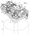
- FIG. 1 illustrates the control valve assembly 10 in fluid communication with the capacitive deionization device 12.
- the control valve assembly 10 is configured to control the flow of supply fluid and treated fluid through the control valve assembly in response to fluctuating fluid demands.
- the capacitive deionization device 12 includes a container 14 that houses the various water treatment components (e.g., flow-through capacitors).
- the container 14 tappers to an upper neck 16 that defines an outer, circular treatment inlet port 18 and an inner, circular treatment outlet port 20 that is nested radially inward of the treatment inlet port 18.
- various other fluid treatment devices can be configured in fluid communication with the control valve assembly 10, and the structure of the control valve assembly 10 can be modified to establish the application specific fluid communication.
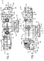
- FIGS. 2 and 3 illustrate that the control valve assembly 10 is coupled to the upper neck 16 by a collar 22.
- the collar 22 is sized to receive the upper neck 16 of the container 14 and is coupled to an annular lip of the upper neck 16 by a split lock ring 24.
- the lock ring 24 has circumferentially spaced tabs 26 that extend radially inward from an outer band 28 of the split lock ring 24. When seated, the tabs 26 extend through aligned rectangular slots 29 formed through the collar 22 and engage the annular lip of the upper neck 16, thus inhibiting removal of the control valve assembly 10 from the capacitive deionization device 12.
- One or more seals can be arranged between the upper neck 16 and the collar 22 to prevent undesirable fluid leakage at the coupling.
- control valve assembly 10 Coupling the control valve assembly 10 to the capacitive deionization device 12 places respective ports of the control valve assembly 10 into fluid communication with the treatment inlet port J 8 and the treatment outlet port 20, thus establishing passageways for fluid communication.
- the control valve assembly 10 includes an inner tube 32 that is coaxially aligned with an outer tube 34 defined by the collar 22. When the control valve assembly 10 is seated on the upper neck 16, the inner tube 32 is brought into fluid communication with the treatment outlet port 20 and the outer tube 34 is similarly brought into fluid communication with the treatment inlet port 18.
- the inner tube 32 is sealed with the treatment outlet port 20 so that a supply fluid flowing from the control valve assembly 10 into the capacitive deionization device 12 is inhibited from mixing with a treated fluid flowing out of the capacitive deionization device 12.
- a flow path is defined from the outer tube 34 of the control valve assembly 10, into the treatment inlet port 18, through the capacitive deionization device 12, out of the treatment outlet port 20, and into the inner tube 32 of the control valve assembly 10.
- the collar 22, the outer tube 34, and the inner tube 32 extend from a valve body 38 of the control valve assembly 10.
- the valve body 38 defines an outlet port 40 and an inlet port 42 that both provide fluid communication into a valve chamber 44 (as also shown in FIGS. 12 and 14-21 .
- the outlet port 40 also establishes fluid communication with the outer tube 34 and the corresponding treatment inlet port 18; similarly, the inlet port 42 establishes fluid communication with the inner tube 32 and corresponding treatment outlet port 20.
- the treatment inlet port 18 will receive a supply fluid from the control valve assembly 10.
- the supply fluid can flow through the balance of the capacitive deionization device 12 to be treated.
- a treated fluid can then flow out of the capacitive deionization device 12 through the treatment outlet port 20 back into the control valve assembly 10.
- the control valve assembly 10 can be in fluid communication with a point of entry (e.g., a residential or commercial water source, such as a well, pressure tank, municipal connection, an upstream fluid treatment device, etc.) that provides the supply fluid, and a point of use (e.g., a residential or commercial water service, such as a water heater, potable water spigot, a downstream fluid treatment device, etc.) that receives the fluid (e.g., treated, untreated, partially treated, blended, etc.) that flows from the control valve assembly 10.
- a point of entry e.g., a residential or commercial water source, such as a well, pressure tank, municipal connection, an upstream fluid treatment device, etc.
- a point of use e.g., a residential or commercial water service, such as a water heater, potable water spigot, a downstream fluid treatment device, etc.
- receives the fluid e.g., treated, untreated, partially treated, blended, etc.
- the valve body 38 of the control valve assembly 10 defines a supply port 46 and a service port 48 that provide the fluid communication between the control valve assembly 10 and the respective point of entry and point of use.
- the valve body 38 can be made, for example, from brass, stainless steel, plastics, or composites, and can be constructed, for instance, by casting, machining, or molding.
- FIGS. 4-8 illustrate a manual bypass body 50 that is coupled to the control valve assembly 10 and connects to a supply conduit and a service conduit.
- the manual bypass body 50 is generally H-shaped and defines a cylindrical external supply port 52 and a cylindrical external service port 54, which are configured to couple with the supply conduit and the service conduits, respectively.
- the external supply port 52 defines a supply chamber 56 and the external service port 54 defines a similar service chamber 58.
- a bypass chamber 60 extends between the supply chamber 56 and the service chamber 58, so that fluid can be directed through the bypass chamber 60 when a supply valve 62 and a service valve 64 are oriented accordingly.
- the supply valve 62 is rotatably seated within the supply chamber 56 so that the supply valve 62 can be rotated ninety-degrees between a flow-through position (shown in FIG. 7 ) and a divert position.
- a flow-through position shown in FIG. 7
- a divert position fluid is allowed to pass though the supply chamber 56 and into the supply port 46 of the control valve assembly 10; in the divert position, fluid is inhibited by the supply valve 62 from flowing into the supply port 46 and is instead redirected into the bypass chamber 60.
- the service valve 64 is rotatably seated within the service chamber 58 so that the service valve 64 can be rotated ninety-degrees between a flow-through position (shown in FIG. 7 ) and a divert position.
- the supply chamber 56 also defines an auxiliary port 66 (shown covered by a cap 68) that can be connected in fluid communication with an auxiliary device (e.g., a drain).
- auxiliary device e.g., a drain
- the manual bypass body 50 further includes a cylindrical supply tube 70 and a cylindrical service tube 72 that are coupled to the valve body 38 by U-clips 74, 76.
- the supply tube 70 is slid over the supply port 46 and the service tube 72 is slid over the service port 48, then the respective U-clips 74, 76 are inserted into openings 78 through the manual bypass body 50 to seat in a series of cylindrical openings 80 formed in the valve body 38.
- the engagement between the U-clips 74, 76, the manual bypass body 50, and the valve body 38 restrains the manual bypass body 50.
- the manual bypass body 50 can be made, for example, from brass, stainless steel, plastics, or composites, and can be constructed, for instance, by casting, machining, or molding. In other embodiments, the manual bypass body 50 (and/or its function) can be integral with the valve body 38.
- the control valve assembly 10 also includes a series of sensors that are positioned within the valve body 38 to monitor various properties of the fluid flowing into, through, and/or out of the control valve assembly 10.
- Other sensors can be incorporated in the overall fluid treatment system to monitor additional properties of the system, such as an ambient temperature and a fluid level or pressure within a treated water storage vessel.
- the sensors monitor aspects of operation and communicate parameters indicative of operation to a controller (e.g., a computer, programmable logic controller, a microcontroller, etc.).
- the controller can control the operation of the control valve assembly 10 in response to and in view of those sensed parameters, as is described below in more detail.
- the controller can be monitoring sensors for parameters that indicate the fluid demand is or will likely exceed the real-time flow capacity of the fluid treatment device.
- the controller can operate the control valve assembly 10 to move the control valve assembly 10 into a position, so that the fluid demand is fulfilled, albeit with partially treated (or blended) fluid.
- Many other control logics can be implemented and tailored to the specific application, including the specifications of the fluid treatment device and other devices incorporated into the overall fluid treatment system.
- a supply pressure sensor 86, a service pressure sensor 88, a supply conductivity sensor 82, and a service conductivity sensor 84 are seated in respective sensor ports 94, 96, 90, 92 formed in the valve body 38.
- the sensor ports 94, 96, 90, 92 extend into desired locations of a manifold 98 that is defined within the valve body 38, and the control logic related to the sensors is discussed in greater detail bellow.
- the supply conductivity sensor 82 and the service conductivity sensor 84 are coupled to respective ports 90, 92 by individual multi-prong clips 100, 102.
- each multi-prong clip 100, 102 includes resilient arms 104, 106 that are inserted into slots 108, 110 formed in respective port collars 112, 114 that extend from the valve body 38. As the multi-prong clips 100, 102 are slid into engagement with the slots 108, 110, the resilient arms 104, 106 flex about the respective bodies 116, 118 of the supply conductivity sensor 82 and the service conductivity sensor 84 until arcuate surfaces 120, 122 conform to a circumferential groove 124, 126 in the bodies 116, 118. Each multi-prong clip 100, 102 also includes a central split prong 128, 130 that seats into a central slot 132, 134 formed in the respective port collar 112, 114.
- each port collar 136, 138 defines a pair of standoffs 140, 142 that define respective cylindrical openings 144, 146 into which U-shaped clips 148, 150 are inserted.
- the U-shaped clips 148, 150 include opposing arms 152, 154 that extend into circumferential grooves 156, 158 formed in bodies 160, 162 of the supply pressure sensor 86 and the service pressure sensor 88.
- the communication connections are not shown in FIG. 8 for clarity, however, the supply pressure sensor 86, the service pressure sensor 88, the supply conductivity sensor 82, and the service conductivity sensor 84 can be in communication (e.g., wired, wireless, one-way, two-way, etc.) with a controller, so that a representative parameter is provided by each sensor to the controller.
- the supply pressure sensor 86 and the service pressure sensor 88 can be part number 2066 manufactured by Marquardt of Rietheim-Weilheim, Germany, and the supply conductivity sensor 82 and the service conductivity sensor 84 can be any suitable conductivity sensor having specifications that accommodate the particular application requirements.
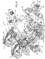
- FIGS. 7 and 9 illustrate an additional sensor and a flow control device being incorporated into the control valve assembly 10 (the manual bypass body 50 has been removed in FIG. 9 for clarity).
- a flow meter 164 is seated within the supply port 46 and includes an outer shell 166 that houses a series of guide vanes 168 and a rotatable blade ring 170.
- the flow meter 164 can be part number GL3027839 manufactured by Pentair Residential Filtration, LLC of Milwaukee, Wisconsin.
- the valve body 38 defines a mount 172 in which a pickup is secured; the pickup can be in communication with the controller to communicate a parameter indicating the flow of the supply fluid into the supply port 46 (e.g., flow or no flow, flow rate, etc.).
- a check valve 174 is seated within the service port 48 to inhibit backflow through the service port 48 into the manifold 98 of the control valve assembly 10.
- the check valve 174 can be part number NV25-25M manufactured by Neoperl, Inc. of Waterbury, Connecticut.
- the manual bypass body 50 captures the flow meter 164 and the check valve 174 within the respective supply port 46 and the respective service port 48 when the manual bypass body 50 is secured to valve body 38, as described above and illustrated in FIG. 7 .
- a controller executing predefined logic can be configured to adjust the operation of the control valve assembly 10 to alter how fluid flows (or is inhibited from flowing) through the manifold 98 of the valve body 38.
- a motor in the form of an electric motor 176 e.g., a direct current electric motor having a magnetic Hall effect pickup in communication with the controller
- the electric motor 176 can be a DC motor, an AC motor, a stepper motor, and the like, such as part number GLBDC-1227-01 manufactured by Global.
- the electric motor 176 and a gear train 178 are mounted to the valve body 38 so that, in some embodiments, rotational movement of the electric motor 176 results in translation of a valve 180.
- the valve 180 is seated within the valve body 38 intersecting the manifold 98 to alter or adjust the operation of the control valve assembly 10.
- the valve body 38 forms a cylindrical mounting flange 182 with a series of fastener bores 184.
- a generally rectangular mounting plate 186 is secured to the mounting flange 182 with several fasteners 188, and a cover 190 is positioned over the gear train 178 and secured to the mounting plate 186 by additional fasteners 192.
- the cover 190 both shields the gear train 178 and provides a mounting location for the electric motor 176.
- the cover 190 forms a cylindrical receptacle 194 having resilient arms 196 that extend from the cover 190 to capture the electric motor 176 to the cover 190.
- the resilient arms 196 define beveled tips 198 that cam against the electric motor 176 during installation and undercuts 200 that engage an end face 202 of the electric motor 176 when fully seated in the cylindrical receptacle 194, thus capturing the electric motor 176.
- the mounting plate 186 and the cover 190 can be made, for example, from brass, stainless steel, plastics, or composites, and can be constructed, for instance, by casting, machining, or molding.
- FIG. 10 illustrates the gear train 178 with the cover 190 removed.
- the electric motor 176 includes a drive motor gear 204 that is rotatably fixed to an output shaft of the electric motor 176.
- the drive motor gear 204 includes teeth 206 that mesh with a first stacked transfer gear 208.
- the first stacked transfer gear 208 includes an outer gear 210 adjacent to an inner gear 212, which is fixed to the outer gear 210, so that the teeth 206 of the drive motor gear 204 are positioned to mesh with the outer gear 210.
- the first stacked transfer gear 208 is rotatably secured to a first spindle standoff 214 extending from the mounting plate 186.
- a second stacked gear 216 supported by a second spindle standoff 218 meshes with both the first stacked transfer gear 208 and a third stacked gear 220 supported by a third spindle standoff 222.
- the third stacked gear 220 meshes with a fourth stacked gear 224 supported by a forth spindle standoff 226, and the fourth stacked gear 224 is in turn meshed with a fifth stacked gear 228 supported by a fifth spindle standoff 230.
- the gear train 178 transfers the rotational movement of the electric motor 176 (in either rotational direction) to a positioning gear 232.
- the various gears can be, for instance, machined, cast, formed from powder metal, or injection molded.
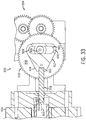
- the positioning gear 232 works in combination with a longitudinal drive gear 242 to convert rotational motion of the electric motor 176 to translational movement of the valve 180.
- the positioning gear 232 is fixed from translation and includes external gear teeth 234 that are engaged by the fifth stacked gear 228 and defines helical threads 236 within a central bore 238.
- the helical threads 236 are configured to engage mating external threads 240 on the longitudinal drive gear 242 that is rotationally fixed. The relative rotation of the positioning gear 232 will cause the longitudinal drive gear 242 to translate through the central bore 238 of the positioning gear 232.
- FIGS. 11, 12 , 14 , and 15 illustrate the interaction between the positioning gear 232, the longitudinal drive gear 242, and the valve 180.
- the positioning gear 232 is inhibited from axial movement but is allowed to rotate.
- the positioning gear 232 is axially restrained or laterally fixed as it is positioned between the cover 190 and a ringshaped bushing 244 seated on a ledge 246 defined by the mounting plate 186 (as shown in FIGS. 14 and 15 ).
- the cover 190 includes an annular, arcuate projection 248 that engages a mating annular, arcuate recess 250 formed on an outside face 252 of the positioning gear 232.
- the bushing 244 defines an annular, arcuate projection 254 that engages another mating annular, arcuate recess 256 formed on an inside face 258 of the positioning gear 232.
- the sliding, rotational engagement between the projections 248, 254 and the recesses 250, 256 allows the positioning gear 232 to rotate and also inhibits translation along a valve axis 260.
- Rotation of the longitudinal drive gear 242 is restrained due to engagement between opposing slots 274 formed axially along the longitudinal drive gear 242 (one of which is shown in FIG. 11 ) and pairs of mating rectangular protrusions 276, 277 (as shown in FIG. 15 ) that extend from an internal surface 278, 279 of the cover 190 and the mounting plate 186, respectively, into the respective slots 274.
- a rod 262 connects the longitudinal drive gear 242 to a piston 264 that is slidably seated within a cartridge cage 266.
- a drive end 268 of the rod 262 defines a groove 270 and a head 272 that is captured to the longitudinal drive gear 242.
- the longitudinal drive gear 242 includes a pair of resilient arms 280 with fingers 282 that extend radially inward toward the groove 270 to capture the rod 262.
- the rod 262 extends from the drive end 268 through an opening 284 in the mounting plate 186 and into the valve chamber 44.
- the mounting plate 186 further includes a cylindrical plug 286 that seats within an end 288 of the valve chamber 44.
- the cylindrical plug 286 includes an annular groove 290 formed in an exterior annular surface 292 in which an o-ring 294 is seated.
- the o-ring 294 seals between the groove 290 and an interior surface 296 of the valve chamber 44.
- An end cup 298 is seated in the cylindrical plug 286 and includes a smaller diameter nipple 300 that extends into a smaller diameter cavity 302 in the cylindrical plug 286 to capture another o-ring 304.
- This o-ring 304 is sized to engage the rod 262 as the rod 262 is translated through the opening 284.
- the rod 262 further defines a valve end 306 that is opposite to the drive end 268 and configured to be captured to the piston 264.
- the piston z-164 can be moved within the cartridge cage 266 along a piston axis 308, which is generally collinear with the valve axis 260.
- the piston 264 is generally cylindrical and extends from a trip end 310 to a base end 312.
- three resilient arms 314 are circumferentially spaced about the base end 312 and are canted radially inward whereat the resilient arms 314 are coupled by a split ring 316.
- the resilient arms 314 and the split ring 316 define an opening 318 that captures another head 320 formed near the valve end 306 of the rod 262.
- the piston 264 is moveable within the cartridge cage 266 to various positions that adjust the flow of fluid through the control valve assembly 10.
- the cartridge cage 266 is seated within the valve chamber 44 and the piston 264 is sized to slidably seat within the cartridge cage 266.
- the cartridge cage 266 includes multiple external seals 322 to seal against an interior cylindrical surface 324 of the valve chamber 44 and additional internal seal 326 to slidably seal against an exterior surface 328 of the piston 264.
- the cartridge cage 266 includes multiple disc ⁇ shaped segments that are snap-fit together to establish seats for the various external seals 322 and the internal seals 326.
- a circular end cap 330 is seated in the valve chamber 44 adjacent to an end wall 332 of the valve chamber 44.
- Resilient tabs 334 extend axially from an interior face 335 of the end cap 330 and include interlocking tips 336 (e.g., an undercut) to engage an adjacent flow disc 338.
- a series of flow discs 338 are interlocked with one or more adjacent flow discs 338.
- Each flow disc 338 includes offset, first and second parallel plates 340, 342 connected by a series of longitudinal spokes 344 proximate interior rims 346, 348 of each plate 340, 342.
- Radial openings 350 are defined between the plates 340, 342 and the spokes 344.
- an annular lip 351 extends axially from the second plate 342 to define a partial seat for an external seal 322 and an internal seal 326. A full seat is formed when adjacent flow discs 338 are coupled.
- the resilient tabs 334 of a first flow disc 338 are aligned with and inserted into arcuate openings 352 (as shown in FIG. 15 ) formed in the first plate 340 of an adjacent flow disc 338, so that the interlocking tips 336 of the first flow disc 338 are engaged with the first plate 340 of the adjacent flow disc 338.
- An end spool 354 includes a first plate 356 similar to the first plates 340 of the flow discs 338, but includes a solid second plate 358 that is coupled to the first plate 356 by a solid cylindrical wall 360,
- the bushing 244, the rod 262, the piston 264, the end cap 330, the flow disc 338, and the end spool 354 can be manufactured from a variety of materials and by numerous techniques.
- the end cap 330, the flow disc 338, and the end spool 354 can be cast from non-corroding metal or injection molded from plastic.
- the rod 262 and the piston 264 can be made from a plastic or metal coated with a friction reducing materials, such as polytetrafluoroethlylene under the trademark Teflon sold by DuPont.
- a friction reducing materials such as polytetrafluoroethlylene under the trademark Teflon sold by DuPont.
- the cartridge cage 266 can include a single sleeve or multiple disc-shaped segments that are not coupled to adjacent segments.
- the end cap 330, the flow discs 338, and the end spool 354 can be integrally formed or abut (without coupling).
- the cartridge cage 266 can be eliminated, such as by integrating the seals into the valve chamber 44 (e.g., o-rings seated in annular recesses formed in an interior surface of the valve chamber 44).
- contours about the exterior surface 328 of the piston 264 influence the available flow area and, in conjunction with the manifold 98, establish or inhibit flow passageway through the valve body 38.
- the piston 264 further defines several flow zones and surfaces between the tip end 310 and the base end 312.
- a tip flow zone 364 is near the tip end 310 and includes three stepped rings 366, 368, 370 of increasing diameter (moving away from the tip end 310 along the piston axis 308).
- a skewed ring 372 having the shape of a conical frustum is adjacent to the final stepped ring 370.
- Adjusting the position of the stepped rings 366, 368, 370 and skewed ring 372 relative to the internal seals 326 will alter the area and hence flow rate of fluid flowing between the tip flow zone 364 and the valve chamber 44. For instance, a larger annular gap between a particular stepped ring 366, 368, 370 and a particular internal seal 326 will allow increased fluid flow through the annular gap, provided other factors remain constant.
- a cylindrically shaped tip seal surface 374 extends from an edge of the skewed ring 372 toward an intermediate flow zone 376.
- the tip seal surface 374 is sized to selectively engage at least one of the internal seals 326 when the piston 264 is seated within the valve chamber 44.
- the intermediate flow zone 376 includes opposing beveled rim 378, 380 and two stepped rings 382, 384. Again, the relative position of the stepped rings 382, 384 can influence the flow of fluid through the intermediate low zone 376.
- a cylindrically shaped intermediate seal surface 386 extends between the intermediate flow zone 376 and a cylindrically shaped base flow zone 388. Similarly to the tip seal surface 374, the intermediate seal surface 386 is sized to selectively engage at once of the internal seals 326 when the piston 264 is seated within the valve chamber 44.
- the base flow zone 388 includes opposing beveled rims 390, 392 bridged by several fingers 394 that extend axially to couple the intermediate seal surface 386 and a base seal surface 396.
- the fingers 394 define circumferentially spaced gaps 398 that allow fluid to flow through the gaps 398 into an interior chamber 400 defined within the piston 264 and along the piston axes 308.
- the base seal surface 396 is further configured to selectively engage at least one of the internal seals 326 when the piston 264 is seated within the valve chamber 44.
- FIG. 13B illustrates a second embodiment of a piston 402 defining a tip flow zone 404 having a generally conical form factor that expands radially outward from a tip end 406 toward a trip seal surface 408.
- the tip flow zone 404 defines a first segment 404A with a first slope and a second segment 404B with a second slope that is less than the first slope of the first segment 404A, thus, the initial and subsequent flow of fluid can be metered.
- An intermediate flow zone 410 includes a beveled rim 412 adjacent to a necked cylindrical portion 414. Another conical surface 416 flares radially outward from the cylindrical portion 414 to another beveled rim 418 having a lesser slope than that defined by the conical surface 416. The beveled rim 418 is adjacent to a cylindrical intermediate seal surface 420, and the balance of the piston 402 is similar to the piston 264 shown in FIG. 13A .
- FIG. 13C illustrates a third embodiment of a piston 422 with a trip flow zone 424 similar to that shown in FIG. 13C .
- the tip flow zone 424 of the piston 422 defines a conical form factor with a generally uniform slope.
- An intermediate flow zone 426 is similar to the stepped version shown in FIG. 13A .
- a fourth embodiment of a piston 428 is shown in FIG. 13D and includes a tip flow zone 430 that incorporates a series of geometric openings 432 circumferentially spaced about the piston 428 near a tip end 434 of the piston 428. As shown in FIG.
- the geometric openings 432 are in the form of an equilateral triangle having a peak 436 proximate to the tip end 434 and a base 440 oriented perpendicular to a piston axis 442 of the piston 428.
- An intermediate flow zone 444 is similar to the piston 402 shown in Fig. 13B.
- FIG. 13E illustrates a fifth embodiment of a piston 446 having a geometric opening 447 in a trip flow zone 450 oriented so that a base 452 of the geometric opening 447 (e.g., in the form of a triangle) is proximate a tip end 455 and perpendicular to the orientation of a piston axis 456.
- An intermediate flow zone 458 is similar to the piston 264 shown in FIG. 13A .
- valve 180 can be manipulated to adjust the internal passageways available through the manifold 98 defined within the valve body 38.
- the position of the piston 264 within the valve chamber 44 adjusts the control valve assembly 10 in to or out of an off position (as shown in FIGS. 14 and 15 ), a service position (as shown in FIGS. 16 and 17 ), a blend position (as shown in FIGS. 18 and 19 ), and a drain position (as shown in FIGS. 20 and 21 .
- control valve assembly 10 can further influence the flow rate of fluid, such as by controlling the size of the passageway through which the fluid flows (e.g., an annular space between the piston 264 and the internal seals 326).
- the various operational modes of the control valve assembly 10 are described below with reference to FIGS. 14-22 .
- FIGS. 14-21 the flow of fluid in each position is generally illustrated with flow arrows and the manual bypass body 50 is not shown in the drawings for clarity.
- the control valve assembly 10 is in an off position at which the valve 180 is configured to inhibit fluid communication between the supply port 46 and the service port 48. Specifically, fluid (e.g., treated fluid) flowing from the treatment outlet port 20 of the capacitive deionization device 12 into the inlet port 42 of the valve body 38 is inhibited from flowing into the valve chamber 44, and thus through the valve chamber 44 into the service port 48.
- fluid e.g., treated fluid
- the point of entry is coupled to the control valve assembly 10 and is configured to provide a supply fluid to the manifold 98 of the control valve assembly 10
- the supply fluid is directed to the supply port 46 and into a supply passageway 460 of the manifold 98.
- the supply conductivity sensor 82 secured to the valve body 38 extends into the supply passageway 460 and provides a conductivity parameter to a controller that is indicative of the fluid conductivity within the supply passageway 460.
- the supply passageway 460 includes arcuate walls 463 that curve toward the valve chamber 44.
- the supply passageway 460 further includes an opening 465 through the valve body 38 into which the supply pressure sensor 86 extends and provides a pressure parameter to a controller that is indicative of a pressure of the supply fluid.
- the base seal surface 396 of the piston 264 is configured to seal with the internal seals 326D, 326E captured in the cartridge cage 266, in order to inhibit the supply fluid within the supply passageway 460 from entering the valve chamber 44.
- the supply passageway 460 establishes a ring-shaped portion 462 about the base seal surface 396 into and through which the supply fluid can flow. With the valve 180 in the off position, supply fluid within the supply passageway 460 can flow out of the manifold 98 through the generally oval outlet port 40, and between the inner tube 32 and the outer tube 34 into the treatment inlet port 18 of the capacitive deionization device 12.
- any fluid (e.g., treated fluid) within the capacitive deionization device 12 is also inhibited front flowing into the valve chamber 44.
- treated fluid entering the manifold 98 through the inlet port 42 which is in fluid communication with the treatment outlet port 20 via the inner tube 32, flows into a treated passageway 464.
- the treated passageway 464 establishes a ring-shaped portion 466 about the tip seal surface 374 and the intermediate sea! surface 386.
- the tip seal surface 374 and the intermediate seal surface 386 are engaged by respective internal seals 326A, 326B to inhibit treated fluid from entering the valve chamber 44.
- a drain passageway 448 is also formed within the manifold 98 and extends from a drain port 449 (as best shown in FIGS. 2 and 4 ) to the valve chamber 44.
- the drain passageway 448 established a ring-shaped portion 451 about the intermediate seal surface 386.
- the intermediate seal surface 386 of the piston 264 seals against the internal seals 326B, 326C to inhibit fluid from flowing between the valve chamber 44 and the drain passageway 448.
- any fluid within a service passageway 454, which is in fluid communication with the service port 48, is hallowed to flow into the valve chamber 44 through the interior chamber 400.
- the fluid can flow through the gaps 398 and past the base end 312 of the piston 264. Fluid flowing through the gaps 398 is directed into an annular compartment 457 that is defined and sealed by external seals 322C, 322D engaged against the valve chamber 44, and internal seal 326C engaged against the intermediate seal surface 386 and internal seal 326D engaged against the base steal surface 396. Fluid flowing past the base end 312 is inhibited from flowing out of the valve chamber 44 by the internal seal 326E, the external seal thy o-ring 304, and the o-ring 294.
- fluid e.g., supply fluid, treated fluid, blended fluid
- the check valve 174 further inhibits fluid from flowing into the manifold 98.
- valve 180 If the valve 180 is not in the off thy electric motor 176 can be actuated by, for instance, a controller to drive the valve 180 to the off position via the gear train 178. Specifically, the rotation of the positioning gear 232 will cause translation of the longitudinal drive gear 242 to the off position illustrated in FIGS. 14 and 15 .
- the actuation of the electric motor 176 is orchestrated by the controller. For instance, the controller can monitor a magnet embedded in, or otherwise fixed to, the first stacked transfer gear 208, so that the controller can monitors rotation of the magnet to "count" the number of rotations of the first stacked transfer gear 208. Given the known gear ratios, each rotation of the first stacked transfer gear 208 corresponds to a linear movement of the longitudinal drive gear 242. In one embodiment, full travel of the piston 264 corresponds to approximately one thousand rotations of the first stacked transfer gear 208, representing approximately one thousand pulses monitored by the controller.
- control valve assembly 10 is configured so that an axial end face 467 of the longitudinal drive gear 242 engages a stop surface 470 formed in a cylindrical cavity 472 of the mounting plate 186.
- the engagement between the stop surface 470 and the axial end face 467 ultimately limits translation of the coupled piston 264, thus not imparting any additional stresses on the piston 264 when positioned in the off position.
- control valve assembly 10 is illustrated in a service position, at which the valve 180 is configured to direct supply fluid flowing into the supply port 46 into the capacitive deionization device 12 and to direct treated fluid flowing from the capacitive deionization device 12 out of the service port 48.
- the control valve assembly 10 provides fluid communication through the manifold 98 to direct supply fluid in the supply port 46 through the supply passageway 460 and into the outlet port 40 that is in fluid communication with the treatment inlet port 18.
- Treated fluid is also directed from the treatment outlet port 20 into the inlet port 42, through the treated passageway 464 into the valve chamber 44, from the valve chamber 44 into the service passageway 454, and ultimately out of the service port 48 to a point of use.
- the service position directs supply fluid into the supply passageway 460 of the manifold 98 where the base seal surface 396 of the piston 264 remains in sealing engagement with the internal seals 326D, 326E, in order to inhibit the supply fluid within the supply passageway 460 from entering the valve chamber 44.
- Supply fluid within the supply passageway 460 flows out of the manifold 98 through the outlet port 40 and into the treatment inlet port 18 of the capacitive deionization device 12. While the relative position of the piston 264 has slid rightward (as shown in FIG.
- flow from the valve chamber 44 through the drain passageway 448 also remains restricted as the intermediate seal surface 386 of the piston 264 seals against the internal seal 326C and the tip seal surface 374 seals against the internal seal 326B, in order to inhibit fluid from flowing between the valve chamber 44 and the drain passageway 448.
- the contoured tip flow zone 364 will be gradually positioned adjacent to the internal seal 326A). Treated fluid will begin to flow through the treated passageway 464, between the internal seal 326A) and the tip flow zone 364, into the valve chamber 44, and along the service passageway 454.
- the skewed ring 372 of the trip flow zone 364 can be positioned relative to the internal seal 326A) to meter the flow of treated fluid.
- the stepped rings 366, 368, 370 of varying diameter can also be positioned relative to the internal seal 326A) to achieve the desired flow rate as the available fluid flow area is adjusted.
- fluid within the service passageway 454 is allowed to flow into the valve chamber 44 through the interior chamber 400.
- the fluid can flow through the gaps 398 and past the base end 312 of the piston 264, but remains sealed in the annular compartment 457 and the valve chamber 44.
- the service conductivity sensor 84 secured to the valve body 38 extends into the service passageway 454 and provides a conductivity parameter to a controller that is indicative of the fluid conductivity within the service passageway 454.
- the service passageway 454 further includes an opening 474 through the valve body 38 into which the service pressure sensor 88 extends (as discussed above) and provides a pressure parameter to a controller that is indicative of a pressure of the treated fluid (when the control valve assembly 10 is in the service position).
- a controller can monitor a flow rate parameter provided by the flow meter 164 and adjust the position of the valve 180 to achieve a desired flow rate.
- a controller can monitor and compare a supply pressure parameter and a service pressure parameter, and adjust the position of the valve 180 to maintain a desired pressure differential.
- the service conductivity sensor 84 can be monitored, so that when the properties of the service fluid exceed a predetermined threshold, the valve 180 can be positioned in the blend position to mix supply fluid with the service fluid thereby adjusting the propertied of the blended fluid within a preferred range.
- the control valve assembly 10 is in a blend position at which the valve 180 is configured to direct a portion of the supply fluid flowing into the supply port 46 toward the capacitive deionization device 12, to direct treated fluid flowing from the capacitive deionization device 12 out of the service port 48, and to direct a portion of the supply fluid to bypass the capacitive deionization device 12 and into the service port 48.
- the control valve assembly 10 provides fluid communication through the manifold 98 to direct supply fluid in the supply port 46 through the supply passageway 460 and into the outlet port 40 that is in fluid communication with the treatment inlet port 18.
- Treated fluid is also directed from the treatment outlet port 20 into the inlet port 42, through the treated passageway 464, into the valve chamber 44, from the valve chamber 44 into the service passageway 454, and ultimately out of the service port 48 to a point of use.
- These two flow paths are similar to those established when the control valve assembly 10 is in the service position.
- the blend position defines an additional flow path that allows the supply fluid and the treated fluid to mix in various ratios to establish a blended fluid that flows from the service port 48.
- the piston 264 In the blend position, the piston 264 is slid further rightward from the service position shown in FIGS. 16 and 17 . As the piston 264 approaches the blend position, the base flow zone 388 moves adjacent to the internal seal 326D), ultimately providing fluid communication between the ring-shaped portion 462 of the supply passageway 460 and the valve chamber 44 through which the supply fluid can flow. Specifically, the supply fluid flows through the gaps 398 into the interior chamber 400 defined within the piston 264. The supply fluid then can flow along the interior chamber 400 toward the service passageway 454 where the supply fluid ultimately mixes with treated fluid entering the valve chamber 44 via the treated passageway 464.
- a controller can receive and use parameters from the supply pressure sensor 86, the supply conductivity sensor 82, the service pressure sensor 88, and the service conductivity sensor 84 to determine the desired position of the valve 180 required to maintain the blended fluid within, for instance, a range of conductivity.
- the service pressure sensor 88 can provide a service pressure parameter that indicates a fluid pressure in the service passageway 454 that is at or below a minimum threshold.
- the controller can determine that the service fluid demands require an increase in fluid pressure and flow. Thus, moving the valve 180 to the blend position will allow additional supply fluid to, at least temporarily, meet the service demands placed on the control valve assembly 10.
- valve 180 can be positioned in the service position or the drain position (discussed below) to allow, for instance, regeneration of the capacitive deionization device 12.
- FIGS. 20 , 21, and 22 illustrate the control valve assembly 10 in a drain position.
- the drain position can be implemented to achieve a variety of functions, such as cleaning the manifold 98 and/or the fluid treatment device 12, regeneration of the fluid treatment device 12, and/or directing waste from the manifold 98 and/or the fluid treatment device 12.
- the piston 264 is positioned to direct supply fluid into the capacitive deionization device 12 via the communication between the outlet port 40 in the valve body 38 and the treatment inlet port 18 in the capacitive deionization device 12, similar to the configuration illustrates for the off position.
- the piston 264 has been slid or translated to generally position the intermediate flow zone 376 of the piston 264 adjacent to the internal sea!
- the drain position in addition to being usable during regeneration of the capacitive deionization device 12 or other water treatment device (e.g., a filter having a filter media), is also useable for cleaning and draining purpose.
- the flow rate is adjusted to be above a minimum level required to prevent scaling and at or below a maximum level required to achieve the desired function (e.g., regeneration-flowing more, fluid than required to regenerate the capacitive deionization device 12 is an inefficient use of fluid, which is preferably avoided).
- FIGS. 23-29 illustrate one alternative control valve assembly 476.
- the control valve assembly 476 includes a generally cubic valve body 478 defining a series of ports, including a supply port 480, a drain port 482, a service port 484, an outlet port 486, and an inlet port 488.
- a point of entry providing a supply fluid can be coupled in fluid communication with the supply port 480 and a point of use can be coupled in fluid communication with the service port 484.
- the outlet port 486 and the inlet port 488 can be configured in fluid communication with respective inlet and outlet ports of a water treatment device (e.g., a capacitive deionization device).
- the control valve assembly 476 is configured to provide selective fluid communication to direct fluid (e.g., supply fluid, treated fluid, blended fluid, drain fluid) between desired ports and to establish multi-port bending.
- a valve chamber 490 is formed within the valve body 478 to house a valve 492.
- the valve 492 includes a piston 494 slidably seated within a cartridge cage 496, which is seated within the valve chamber 490.
- the cartridge cage 496 further includes external seals 498 in engagement with the valve chamber 490 and internal seals 500 in engagement with the piston 494, As the piston 494 slides along a valve axis 502 within the valve chamber 490, the internal seals 500 wipe against the piston 494 to establish various flow passageways through a manifold 504 defined within the valve body 478.
- the piston 494 can be moved between various positions by a similar arrangement described above with reference to the piston 264 or by any other appropriate construction.
- FIG. 25 illustrates the alternative control valve assembly 476 in an off position at which fluid entering the inlet port 488 is inhibited from flowing out of the service port 484.
- a supply fluid enters the supply port 480 and flows through a supply passageway 506 toward the valve chamber 490.
- the internal seals 500D, 500E seal against a base seal surface 508 of the piston 494 to inhibit supply fluid from entering the valve chamber 490.
- the supply fluid also flows along an elongated outlet passageway 510 to the coupled fluid treatment device. Fluid can enter the manifold 504 via the inlet port 488 where if flows along an inlet passageway 512 toward the valve chamber 490.
- sealing engagement between the internal seal 500A and a tip seal surface 514, and between the internal seal 500C and an internal seal surface 524 directs the fluid toward the drain port 482.
- Fluid within a service passageway 516 can flow through gaps 518 in a base flow zone 520 into a fluid receptacle 522, which is defined by internal seals 500C, 500D engaged with the internal seal surface 524 and the base seal surface 508, respectively.
- Fluid flowing toward a base end 526 of the piston 494 can be contained in a similar manner described with reference to the control valve assembly 10.
- FIG. 26 illustrates the control valve assembly 476 in a service position at which supply fluid is in fluid communication with the fluid treatment device and treated fluid is in fluid communication with the service port 484. Specifically, supply fluid is directed as described when the control valve assembly 476 is in the off position, but the piston 494 is moved to the position shown in FIG. 26 . In the service position, treated fluid entering the inlet port 488 flows through the inlet passageway 512 to the valve chamber 490. The treated fluid then flows along a tip flow zone 528 between the piston 494 and the internal seal 500A into the service passageway 516.
- the tip flow zone 528 includes tapered steps 530 that transition to a necked portion 532 that can be positioned to adjust the flow rate of fluid passing through the tip flow zone 528.
- the necked portion 532 is adjacent to a beveled rim 534 that flares radially outward toward a bypass seal surface 536 (describe below).
- Internal seal 500B seals against the tip seal surface 514 to inhibit fluid from flowing along a drain passageway 538 to the drain port 482. Fluid flowing through the gaps 518 in the base flow zone 520 continues to be directed into the fluid receptacle 522.
- FIG. 27 illustrates the control valve assembly 476 in a blend position at which a blended fluid is directed from the service port 484.
- the piston 494 directs the supply fluid both through the outlet passageway 510 for treatment by the fluide treatment device and through the valve chamber 490 where it is mixed with treated water flowing through the inlet passageway 512.
- supply fluid is directed through the gaps 518 in the base flow zone 520 toward the service passageway 516.
- Supply fluid is also directed along the outlet passageway 510, through the outlet port 486, and in to the fluid treatment device.
- Treated fluid from the fluid treatment device enters the valve body 478 via the inlet port 488 and flows along the inlet passageway 512 toward the valve chamber 490.
- the tip flow zone 528 is positioned to extend across the internal seal 500A so that treated fluid can flow between the internal seal 500A and the necked portion 532 toward the service passageway 516.
- the treated fluid and the supply fluid mix to establish a blended fluid that then is directed from the service port 484.
- the control valve assembly 476 further includes a bypass position (as shown in FIG. 28 ) at which supply fluid is directed from the supply port 480, through the valve chamber 490, and from the service port 484, without mixing with treated fluid provided by a fluid treatment device.
- the piston 494 is positioned so that the base now zone 520 is adjacent to the supply passageway 506.
- Supply fluid flows through the gaps 518 and along the valve axis 502 toward the service passageway 516.
- Supply fluid can flow through the outlet passageway 510, however, internal seals 500A, 500B engage the bypass seal surface 536 and the tip seal surface 514, respectively, to inhibit treated fluid from entering the service passageway 516.
- the supple fluid bypasses the fluid treatment device and is directed downstream to the service port 484.
- the control valve assembly 476 includes a drain position, as shown in FIG. 29 .
- the control valve assembly 476 directs supply fluid though the outlet passageway 510 and directs fluid in the inlet passageway 512 through the valve chamber 490, to the drain passageway 538, and ultimately out of the drain port 482.
- fluid enters the inlet port 488 and flows along the inlet passageway 512 to the valve chamber 490.
- the piston 494 is slid within the valve chamber 490 to the position shown in FIG. 29 to align an intermediate flow zone 542 and the internal seal 500B. The alignment results in fluid flowing between the piston 494 and the internal seal 500B toward the drain passageway 538 (as shown in FIG. 24 ).
- the intermediate flow zone 542 further includes stepped rings 544, 546 that can be positioned relative to the internal seal 500B to meter or adjust the flow of fluid as the size and form of the opening is altered.
- FIG. 30 illustrates a control valve assembly 548 in communication with a controller 550 to control the movement of the control valve assembly 548 between various positions (e.g., an off position, a service position, a blend position, a bypass position, a drain position, etc.). While the controller 550 can operate without receiving parameters from sensors (e.g., such as by adjusting the position based on timers, temporal schedules, direct input from a user, etc.), the controller 550 is illustrated as being in communication with a supply sensor 552, a service sensor 554, and a system sensor 556.
- a supply sensor 552 e.g., a service sensor 554, and a system sensor 556.
- the controller 550 is configured to adjust (e.g., translate) the control valve assembly 548 to direct fluid from and between a point of entry 558, a fluid treatment device 560, a point of use 562, and a drain 564.
- the control valve assembly 548 includes a supply port 566 in fluid communication with the point of entry 558, an outlet port 568 in fluid communication with a treatment inlet port 570, an inlet port 572 in fluid communication with a treatment outlet port 574, a service port 576 in fluid communication with the point of use 562, and a drain port 578 in communication with the drain 564.
- the controller 550 can monitor the service sensor 554 (e.g., a pressure sensor) so that when the service pressure is below a minimum level (indicating that a demand for fluid exists), the controller 550 can adjust the control valve assembly 548 from the off position to the service position.
- the service sensor 554 e.g., a pressure sensor
- the controller 550 can monitor the system sensor 556 for a parameter indicative of the fluid level or pressure in a treated water storage tank. If the controller 550 determines that the demand for treated water (as indicated by a low fluid level or slow pressure within the treated water storage tank) exceeds the throughput capacity of the fluid treatment device 560, the controller 550 can adjust the valve to the blend position. Specifically, a motor can be operatively coupled to the valve and the controller 550. The controller 550 communicates with the motor to energize the motor and thus adjust the control valve assembly 548 to the blend position, or a particular position within a range of blend positions depending on the calculated fluid demand.
- both the supply fluid and the treated fluid are directed through the service port 576 so that a blended fluid (comprising the supply fluid and the treated fluid) is directed from the valve body to the point of use 562, either directly or indirectly via a treated water storage tank.
- the controller 550 can adjust the control valve assembly 548 to the bypass position, so that supply fluid is routed from the supply port 566 to the service port 576, without being inhibited by the limited throughput of the fluid treatment device 560. Fluid communication with the fluid treatment device 560 can be restored, for instance, when the service sensor 554 (e.g., a flow meter) monitored by the controller 550 indicates a reduced demand that will allow the fluid treatment device 560 to again treat at least a portion of the supply fluide entering the control valve assembly 548.
- the service sensor 554 e.g., a flow meter
- the service sensor 554 can include a conductivity sensor providing a parameter indicative of the conductivity of the fluid flowing through the service port 576. If the controller 550 monitoring the service sensor 554 determines that the conductivity of the service fluid is outside of an acceptable range, the controller 550 can actuate the control valve assembly 548 to the blend position or the service position, in order to maintain the integrity of the service fluid at the expense of decreased fluid throughput. In another example, if the controller 550 monitoring the service sensor 554 determines that the conductivity of the service fluid is outside of an acceptable range, the controller 550 can determine that regeneration of the fluid treatment device 560 is required and move the control valve assembly 548 to the drain position.
- the supply sensor 552 connected to the controller 550 communicates a supply parameter to the controller 550
- the service sensor 554 which is also connected to the controller 550 communicates a service parameter to the controller 550.
- the controller 550 is configured to monitor the supply parameter and the service parameter of the blended fluid, and to determine or calculate a difference between the supply parameter and the service parameter. The difference is then compared to a threshold or desired level and the position of the control valve assembly 548 is adjusted to alter the blend position accordingly to target the threshold.
- this logic can define a control loop carried out by the controller 550 as a technique to monitor and maintain the properties of the fluid exiting the control valve assembly 548 at a threshold, a level, or within a range.
- the controller 550 can be configured to communicate with a variety of sensor types.
- the supply sensor 552, the service sensor 554, and the system sensor 556 can include one or more of the following types of sensors: a system temperature sensor (e.g., to sense the ambient temperature), a system pressure sensor (e.g., to sense the pressure within a system storage tank.), a system fluid volume sensor (e.g., to sense the fluid volume or level within a system storage tank), a fluid temperature sensor (e.g., to sense the temperature of the supply fluid), a flow sensor (e.g., to sense the flow rate of fluid entering or exiting the control valve assembly 548), a flow pressure sensor (e.g., to sense the pressure of the fluid entering or exiting the control valve assembly 548), a conductivity sensor (e.g., to sense the conductivity of the fluid flowing through the control valve assembly 548), and a pH sensor (e.g., to sense the pH of the fluid flowing through the control valve assembly 548).
- a system temperature sensor e
- the controller 550 can monitor the sensors and adjust the position of the control valve assembly 548 in response to the sensed parameters. For instance, the controller 550 can monitor an ambient temperature sensor and adjust the control valve assembly 548 from an off position to a drain position if the ambient temperature exceeds a threshold, in order to use the supply fluid as a heat sink to extract heat from the control valve assembly 548 and/or the fluid treatment device 560. In other embodiments, the controller 550 can monitor a temperature of the supply fluid and adjust the control valve assembly 548 if the temperature of the supply fluid exceeds a threshold, in order to prevent supply fluid having an excessive temperature from flowing through the fluid treatment device 560 and potentially damaging the fluid treatment device 560.
- the controller 550 can monitor a flow meter for a parameter indicative of slow supply fluid flow or fast service fluid flow, and adjust the position of the control valve assembly 548 to direct additional fluid through the control valve assembly 548 as needed.
- the parameter can also be indicative of a no flow condition, at which power to the fluid treatment device 560 can be reduced or turned off until fluid demand is again indicated.
- FIG. 31 shows a simplified schematic of another embodiment of a control valve assembly 600.
- a controller 602 is in communication with a sensor 604, a motor 606, and an energy reserve 608.
- the motor 606 is coupled to a valve 610 that is seated within a valve body 612. Energizing the motor 606 can selectively move the valve 610 between an operating position and a fault position.
- the control valve assembly 600 can be in, for instance, the service position, the blend position, the bypass position, or the drain position discussed above.
- the fault position can be, for instance, the off position, the service position, the blend position, the bypass position, or the drain position.
- the position of the valve 610 that is associated with the operating position and the service position can be selected depending on, for instance, the type of water treatment system the control valve assembly 600 is coupled to and/or the type of fault condition encountered by the control valve assembly 600.
- the energy reserve 608 is shown operationally coupled to the controller 602, the sensor 604, and the motor 606. As a result, the energy reserve 608 can provide energy to operate the coupled devices if the control valve assembly 600 experiences a fault condition in the form of a line energy loss (e.g., line power to the controller 602 is interrupted temporarily or for an extended period).
- the energy reserve 608 can include various energy storage devices, such as a battery or a capacitor that are of sufficient capacity (e.g., amp-hours) to power at least one of the controller 602, the motor 606, and the sensor 604 to move the valve 610 to the desired fault position after a loss of line energy.
- the sensor 604 can be any suitable type of sensor (e.g., a line energy sensor, a valve position sensor, a temperature sensor, a flow sensor, a current sensor, a pressure sensor, etc.) that senses some property 614 of the control valve assembly 600 or the overall water treatment system that the control valve assembly 600 is integrated into.
- the controller 602 monitors the sensor 604 to receive a fault signal from the sensor 604 that indicates a fault condition of the control valve assembly 600 or the overall water treatment system.
- the controller 602 can energize the motor 606 (e.g., an electric motor or a hydraulically actuated motor) to drive the valve 610 to the fault position.
- the motor 606 e.g., an electric motor or a hydraulically actuated motor
- the senor 604 can be a conductivity sensor that provides a fault signal when the conductivity sensor fails to communicate (or indicates a fault in the conductivity sensor).
- the controller 602 in response to the fault signal, actuates the motor 606 to drive the valve 610 to the blend position (i.e., one type of fault position), and can also indicate (e.g., via a display, audible tone, etc.) that a fault of the control valve assembly 600 has occurred.
- the blend position a blended fluid including the supply fluid and the treated fluid is directed from the valve body 612 to the point of use.
- the senor 604 can include a line energy sensor that provides a fault signal indicative of a loss of line energy to the control valve assembly 600.
- the energy reserve 608 can be electrically integrated to provide near continuous (i.e., substantially uninterrupted) power to the controller 602, the sensor 604, and the motor 606.
- the controller 602 can control the motor 606 to drive the valve 610 to the fault position, such as a bypass position, by drawing on powder supplied by the energy reserve 608.
- the control valve assembly 600 can be moved to the bypass position via energy provided by the energy reserve 608, so that fluid can pass through the control valve assembly 600 to the point of use even if the control valve assembly 600 is without line power.
- FIG. 31 schematically shows the energy reserve 608 and the sensor 604 as separate from the controller 602, one or both can be integral with the controller 602.
- the energy reserve 608 is integral with the controller 602 (e.g., an on-board capacitor or battery).
- Other embodiments of the control valve assembly 600 include a motor having a sensor (e.g., a Hall effect sensor) that is in communication with the controller 602 and also operationally coupled to the energy reserve 608.
- the controller 602 can monitor the sensor to adjust the position of the valve 610 from an operating position to the desired fault position, even in situations of line energy loss.
- FIG. 32 is a flow chart showing an example fault control loop executed by the controller 602.
- the controller 602 monitors the sensor 604 at Step 616 for a fault signal indicating a fault condition (e.g., excess motor temperature, line energy loss, no fluid flow, etc.). If no fault condition is identified at Step 618, the controller 602 returns to monitoring the sensor 604 for a fault signal at Step 616. If a fault condition is identified at Step 618, the controller 602 moves the valve 610 to the fault position at Step 620.
- the fault position can be predetermined or selected in accordance with logic that factors the specific type of water treatment device and the instant fault condition.
- the controller 602 can adjust the position of the valve 610 by energizing the motor 606 to drive the valve 610 from the operating position to the appropriate fault position.
- the controller 602 continues to monitor the sensor 604 to determine if the fault condition has been corrected. If the fault conditions remains, the valve 610 is maintained in the fault position. If the fault condition was indicative of a loss of line energy, the controller 602 can be configured to shut down once the valve 610 is in the fault position (e.g., the bypass position). If the fault condition has been corrected, the controller 602 can be configured to move the valve 610 to the operating position at Step 624. The controller 602 then resumes monitoring the sensor 604 at Step 616.
- the fault condition may also be remedied with user interaction.
- the controller 602 can include a display that provides information regarding the fault condition and an input device that required that a user acknowledge or take additional action to remedy the fault before the controller 602 resumes operation of the control valve assembly 600.
- the controller 602 can compare a current position of the valve 610 to the desired fault position (e.g., a blend position) and adjust the position of the valve 610 from the current position to the fault position.
- the controller 602 can monitor the current position of the valve 610 using various techniques, including a magnetic pickup with pulses corresponding to linear movement of the valve 610, optical sensors, and other position sensors.
- the controller 602 can also include application-specific logic that is tailored to the type of system (e.g., electrochemical deionization device, capacitive deionization device, water softener, water filter, etc.) that the control valve assembly 600 is in communication with. For instance, if the system includes an electrochemical deionization device and the fault condition indicates a line energy loss, the controller 602 can control the motor 606 to move the valve 610 to the bypass position to allow supply fluid to flow uninhibited through the control valve assembly 600 to the point of use. Alternatively, if the system includes a water filter, the controller 602 can control the motor 606 to move the valve 610 to a service position when a jammed valve 610 fault condition is indicated in order to maintain some level of filtration.
- application-specific logic that is tailored to the type of system (e.g., electrochemical deionization device, capacitive deionization device, water softener, water filter, etc.) that the control valve assembly 600 is in communication with. For instance, if the
- the sensor 604 can be monitoring a variety of aspects of the overall water treatment system.
- the sensors 604 can include a flow meter within the valve body 612, at the point of entry, or at the point of use that can be monitored by the controller 602 to determine if there is an unexpected flow of fluid (e.g., flow to the point of use when the valve 610 is in the off position).
- the controller 602 may include a timer that monitors the elapsed time to move the valve 610 a full stroke or cycle. This elapsed time can be compared to a predetermined or a typical elapsed time.
- a fault condition e.g., indicative of a binding/jammed valve, a motor fault, etc.
- the controller 602 moving the valve 610 to the associated fault position (e.g., the off position) where the control valve assembly 600 can be serviced.
- the controller 602 can move the valve 610 to a nominal position at the beginning of a cycle (e.g., at initial power up of the control valve assembly 600, after a drain cycle, etc.). The controller 602 can then move the valve 610 to a first position while monitoring the sensor 604. For instance, the controller 602 may monitor a flow meter and control the motor 606 to drive the valve from an off position to a service position. If the controller 602 receives a fault signal from the flow meter (e.g., a no-flow signal), despite the presumed movement of the valve 610 into the service position, the controller 602 can move the valve 610 to a fault position (e.g., an off position).
- a fault position e.g., an off position
- the communication between the controller 602 and the sensor 604 allows the control valve assembly 600 to establish the desired operating conditions and provides a point of reference to allow the valve 610 to be positioned for flow control, which benefits from accurate positioning.
- the controller 602 can also be programmed to recalibrate the position of the valve 610 at specific times or intervals (e.g., number of cycles, point in cycle, etc.).
- FIG. 33 illustrates an alternative drive configuration.
- An eccentric drive arrangement 900 includes a drive gear 902 that is engaged by, for example, an electric motor via a gear train 904.
- the drive gear 902 includes an eccentric mount 906 that protrudes from a side face 908 of the drive gear 902.
- the eccentric mount 906 is sized to slidably engage a slot 910 formed in a triangular yoke 912.
- a tapered end 914 of the yoke 912 is fixed coupled to an end 916 of a rod 918.
- a piston 920 is engaged with an opposite end 922 of the rod 918.
- the mechanics of the eccentric drive arrangement 900 cause translation off the piston 920 in response to rotation of the drive gear 902. Specifically, as the eccentric mount 906 on the drive gear 902 traverses a circular path relative to a stationary valve body 924, the yoke 912 is translated along a valve axis 926 as the eccentric mount 906 oscillates between ends 928, 930 of the slot 910. The translation of the yoke 912 results in translation of the attached rod 918 and piston 920, allowing the position of the piston 920 to be adjusted.
- Alternative motors can also be incorporated into the control valve assembly concept. For instance, hydraulically actuated motors chamber and bellows) can be configured to move a piston of an alternative control valve assembly.
- FIG. 34 shows an embodiment of a control valve assembly 800 mounted to an embodiment of a capacitive deionization device 802. Similar to the control valve assembly 10, the control valve assembly 800 is in fluid communication with the capacitive deionization device 802.
- the capacitive deionization device 802 includes a vessel 804 that defines a chamber 806.
- a series of flow-through capacitors 808 are seated within the chamber 806 on a floor 810 of the chamber 806. The series of flow-through capacitors 808 are compressed between the floor 810 and a compression element 812.
- the flow-through capacitor 808 includes a stack of individual fluid processing cells. Each cell in the stack includes one or more of a combination of the following elements: electrode pairs, cation membranes, anion membranes, and flow spacers, which are typically made of a plastic mesh. While the cation and anion membranes may be used to provide improved attachment and storage of the constituents on the electrodes, the membranes are not required and the cells can be manufactured without them. Additionally, the electrode may be constructed to have a two-part electrode construction including a carbon adsorptive electrode layer and a current collector.
- each of these cell elements is in the form of a relatively thin layer (with a central opening) that is disposed in parallel with the other layers and stacked upon one another in a repeating pattern of first electrode / cation membrane / spacer / anion membrane / second electrode / anion membrane / spacer / cation membrane. After the last cation membrane, there can be another first electrode and the pattern can be repeated. Since any flux of charged constituents occurs as the result of a voltage difference created between the first and the second electrodes, electrode layers can form the bottommost and topmost layers of the stack.
- the flow-through capacitor 808 includes many electrode pairs.
- each electrode pair includes a first electrode (which during treatment acts as a cathode) and a second electrode (which during treatment acts as an anode).
- the electrodes may be constructed from high-surface area electrically conducting materials such as, for example, activated carbon, carbon black, carbon aerogels, carbon nanofibers, carbon nanotubes, graphite, graphene, or mixtures thereof.
- the electrodes can be placed as a separate layer on top of a current collector or can alternatively be coated directly onto the current collector.
- the electrodes are configured and electrically connected relative to each other to establish a voltage difference or potential there between.
- the first electrodes in the flow-through capacitor 808 can be connected to one another and are then connected to a power supply.
- the second electrodes in the flow-through capacitor 808 can be connected to one another and are then connected to the power supply.
- the electrodes can be connected to one another at their outer edges using peripheral tabs that contact one another or using other forms of connection.
- the stack can be arranged so that nearest neighbor electrodes will be of different kinds (i.e., the first electrodes will be disposed between the second electrodes and vise-versa),
- the various electrode sets may be interleaved with one another and arranged so as to place multiple electrode pairs in series with one another.
- first and second electrodes can be differently charged from one another to establish a voltage potential across the electrodes pairs.
- This voltage potential can be used to either draw charged constituents out of the fluid toward the electrodes (such as during treatment) or release the collected constituents back into the fluid (such as during regeneration, discharge, or cleaning).
- Cation membranes and anion membranes are positioned adjacent to the first electrode and the second electrode, respectively. The cation membrane and the anion membrane act as charge barriers that can be placed between the electrodes and the centrally-disposed flow spacer.
- charge barrier refers to a layer of material that can hold an electric charge and that is permeable or semi-permeable for ions.
- a charge barrier may allow an increase in ion removal efficiency as well as a reduction in the overall energy consumption for ion removal.
- the plastic mesh flow spacer is disposed between the cation membrane and the anion membrane (and the corresponding electrode pair).
- This mesh spacer has a pattern similar to a window screen and also has some sections that are thicker than others sections in the height dimension (the height dimension is generally perpendicular to the direction of flow through the spacers) so that, when the spacer layer is lightly compressed between two other layers (e.g., the cation membrane and the anion membrane) fluid is able or permitted to flow across the spacer layer and between the corresponding pairs of electrodes.
- a flow-through capacitor will likely include tens or hundreds of electrode pairs to provide an appropriate amount of surface area for deionization of a usable amount of treated fluid.
- multiple modules or trays of cell components can be constructed containing a number of electrode pairs that are stacked on one another and the trays separately or aggregately compressed. Additionally, the various layers of the stack are compressed to control the amount of space between the cell components, thereby establishing a cross-section area through which the fluid can flow through the stack. This compression may be done in a number of ways.
- a pressure plate e.g., compression element 812
- at the top of the flow-through capacitor can compress the cell components or layers in a direction perpendicular to the direction of fluid flow through the stack.
- a pressure plate can apply a variable compressive force by mechanical fastening (e.g., employing a threaded screw element which may be tightened or loosened to adjust compressive force).
- mechanical fastening e.g., employing a threaded screw element which may be tightened or loosened to adjust compressive force.
- the stack may be divided into multiple portions with each portion being separately compressible.
- the control valve assembly 800 shown in FIG. 34 includes a valve body 814 with a collar 816 that is mounted on the vessel 804.
- An outlet port 818 of the control valve assembly 800 is in fluid communication with a treatment inlet port 820 of the capacitive deionization device 802, and an inlet port 822 is in fluid communication with the treatment outlet port 824 of the capacitive deionization device 802.
- control valve assembly 800 When the control valve assembly 800 is in the service position or the blend position, supply fluid flowing from the control valve assembly 800 flows through the outlet port 818, into the treatment inlet port 820, and into the chamber 806 of the vessel 804.
- the supply fluid flows radially inward through the flow-through capacitors 808 toward a central column 826. Treated fluid then flows along the central column 826 a toward passageway 828 formed through the compression element 812.
- the passageway 828 defines the treatment outlet port 824 that is in fluid communication with the inlet port 822 of the control valve assembly 800. Treated fluid flows into the inlet port 822 and is directed through the control valve assembly 800 to the point of use. In some instances or operational cycles, fluid can be directed through the flow-through capacitor 808 in a reverse direction.
- the flow-through capacitor 808 there can be multiple water inlets or structures that promote an even or otherwise desirable fluid flow pattern through the flow spacers in the stack. There can be additional structural elements that are used to position, electrically connect, and/or compress some or all of the cell elements in the stack.
Description
- Valves are used in a wide variety of applications to generally control and/or direct the flow of fluids. In one example application, valves are used to control the flow of water through water treatment systems installed in residential and/or commercial settings. These water treatment systems include, for instance, water treatment devices such as water filters and conditioners that extract and/or replace undesirable constituents in the supplied water.
- One type of water treatment device, generally referred to as a capacitive deionization device, can be used to remove electrically-charged impurities, such as ions, from a water supply. In capacitive deionization devices, a stream of water passes through one or more flow-through capacitors that include pairs of polarized electrode plates. To remove impurities from the supply water passing between the electrode plates, a voltage potential is established between the electrode plates that causes many impurities in the supply water to be attracted to and (at least temporarily) retained on one of the electrode plates, while the comparatively purified water flows from the capacitor.
- The efficiency and capacity of the electrode plates are reduced during use as impurities extracted from the supply water increasingly saturate the electrode plates. To regenerate the capacity of a flow-through capacitor, the flow-through capacitor can be set to discharge the captured impurities by removing the voltage potential or by temporarily applying a voltage potential in an opposite polarity to the voltage potential established during purification. During discharge, the effluent water carrying the impurities is typically routed to a drain line.
- In general, operation of most water treatment devices includes some form of a service/cleaning cycle. One or more valves can be used to adjust the water treatment device between a service state and a cleaning state. If the cycle is interrupted (e.g., a loss of line power or fluid pressure to the water treatment device), the effectiveness and efficiency of a particular cycle or of the overall device can be reduced. Sophisticated water treatment devices, such as capacitive deionization devices, arc susceptible to malfunction if operated. under certain conditions (e.g., without adequate fluid flow, without proper regeneration cycles, etc.). Operation of water treatment devices relies, at least in part, on adequate control of fluid to, through, and from the water treatment device, even when fault conditions are encountered.
WO 2011/061310 A1 discloses a water supply and monitoring system comprising a first water pipe; a particle sensor for sensing particles in the water at a first location in said pipe; a second pipe, in fluid communication with the first pipe by means of a first valve disposed at a second location on the first pipe downstream of the first location; a third pipe, in fluid communication with the first pipe at a location between the first and second locations; a second valve allowing water conveyed by the first pipe to flow into the third pipe. A method using said arrangement, comprising determining a content of particles in the water in the first pipe; triggering closure of the first valve and opening of the second valve when the determined content of particles is higher than a predetermined level, whereby water flowing in the first pipe is diverted from second pipe into third pipe.
US 2007/262024 A1 discloses a method for fluid treatment that provides alternative regeneration cycles within the same fluid treatment device. A second alternative regeneration cycle is available within the same device, which has independent cycles or processes from the first regeneration cycle. The first and second regeneration cycles can be programmed at the same time and be programmed to alternatively run based upon the number of individual cycles run, the time the cycles have run, the amount of fluid that has passed through the device, or the concentration of brine and/or chlorine in the fluid within the device. - In light of at least the above, a need exists for a control valve assembly incorporating an improved design concept that can accommodate the unreliable and fluctuating operating conditions in which water treatment systems encounter fault conditions.
- In accordance with a first aspect of the present invention there is provided a control valve assembly as defined in claim 1.
In accordance with a second aspect of the present invention there is provided an electrochemical deionization system including an electrochemical deionization device and the control valve assembly of the first aspect, as defined in claim 6.
In accordance with a third aspect of the present invention there is provided a method of fault detection for a control valve assembly as defined inclaim 7. -
-
FIG. 1 is an isometric view of an example control valve assembly coupled to an example water treatment device. -
FIG. 2 is a bottom isometric view of the example control valve assembly. -
FIG. 3 is a bottom plan view of the example control valve assembly, -
FIG. 4 is an end plan view of the example control valve assembly. -
FIG. 5 is a left side plan view of the example control valve assembly. -
FIG. 6 is a right side plan view of the example control valve assembly -
FIG. 7 is a top plan, partial section view of the example control valve assembly. -
FIG. 8 is a partially exploded, isometric view of the example control valve assembly illustrating example pressure sensors and example conductivity sensors. -
FIG. 9 is a partially exploded, isometric view of the example control valve assembly illustrating an example check valve and an example flow meter. -
FIG. 10 is a partial isometric view of an example gear train of the example control valve assembly. -
FIG. 11 is an isometric view of a portion of the example control valve assembly. -
FIG. 12 is a section view along line 12-12 shown inFIG. 11 illustrating the portion of the example control valve assembly in an example valve chamber. -
FIG. 13A is a plan view of an example piston shown inFIGS. 11 and 12 . -
FIG. 13B-13E are partial plan views of alternative example pistons. -
FIG. 14 is a section view along line 14-14 shown inFIG. 4 illustrating the example control valve assembly in an off position. -
FIG. 15 is a section view along line 15-15 shown inFIG. 4 illustrating the example control valve assembly in the off position shown inFIG. 14 . -
FIG. 16 is a section view illustrating the example control valve assembly in a service position. -
FIG. 17 is a section view illustrating the example control valve assembly in the service position shown inFIG. 16 . -
FIG. 18 is a section view illustrating the example control valve assembly in a blend position. -
FIG. 19 is a section view illustrating the example control valve assembly in the blend position shown inFIG. 18 . -
FIG. 20 is a section view illustrating the example control valve assembly in a drain position. -
FIG. 21 is a section view illustrating the example control valve assembly in the drain position shown inFIG. 20 . -
FIG. 22 is a detail view of the portion ofFIG. 21 circumscribed by arc 22-22 shown inFIG. 21 . -
FIG. 23 is an isometric view of an alternative example control valve assembly. -
FIG. 24 is a partial section view along line 24-24 shown inFIG. 23 of the alternative example control valve assembly. -
FIG. 25 is a partial section view of the alternative example control valve assembly in an off position. -
FIG. 26 is a partial section view of the alternative example control valve assembly in a service position. -
FIG. 27 is a partial section view of the alternative example control valve assembly in a blend position. -
FIG. 28 is a partial section view of the alternative example control valve assembly in a bypass position. -
FIG. 29 is a partial section view of the alternative example control valve assembly in a drain position. -
FIG. 30 is a schematic of an example fluid treatment system. -
FIG. 31 is a schematic of an example control valve assembly. -
FIG. 32 is a flow chart illustrating operation of an example control valve assembly. -
FIG. 33 is a partial cross section view of an alternative motor configuration. -
FIG. 34 is a partial section view of an example capacitive deionization device including an example control valve assembly. - Before any embodiments of the invention are explained in detail, it is to be understood that the invention is not limited in its application to the details of construction and the arrangement of components set forth in the following description or illustrated in the following drawings. The invention is capable of other embodiments and of being practiced or of being carried out in various ways. Also, it is to be understood that the phraseology and terminology used herein is for the purpose of description and should not be regarded as limiting. The use of "including," "comprising," or "having" and variations thereof herein is meant to encompass the items listed thereafter and equivalents thereof as well as additional items. Unless specified or limited otherwise, the terms "mounted," "connected," "supported," and "coupled" and variations thereof are used broadly and encompass both direct and indirect mountings, connections, supports, and couplings. Further, "connected" and "coupled" are not restricted to physical or mechanical connections or couplings.
- The following discussion is presented to enable a person skilled in the art to make and use embodiments of the invention. Various modifications to the illustrated embodiments will be readily apparent to those skilled in the art, and the generic principles herein can be applied to other embodiments and applications without departing from embodiments of the invention. Thus, embodiments of the invention are not intended to be limited to embodiments shown, but are to be accorded the wildest scope consistent with the principles and features disclosed herein. The following detailed description is to be read with reference to the figures, in which like elements in different figures have like reference numerals. The figures, which are not necessarily to scale, depict selected embodiments and are not intended to limit the scope of embodiments of the invention. Skilled artisans will recognize the examples provided herein have many useful alternatives and fall within the scope of embodiments of the invention.
- One embodiment of a control valve assembly with multi-port blending ("control
valve assembly 10") is described in the context of a fluid treatment device. The fluid treatment device is shown and described in the form of acapacitive deionization device 12. However, the embodiments described herein can be incorporated into other suitable types of fluid treatment devices, such as an electrodeionization device, a continuous electrodeionization device, an electrodialysis device, a capacitive deionization device including a flow-through capacitor, a carbon filter device, a reverse osmosis device, or a water softener device (e.g., including a resin bed). In one embodiment, an electrodeionization device performs a process that uses electrically active media and electrical potential to influence ion movement within a liquid. Electrodeionization devices can include media that has a permanent or a temporary charge and is operated to cause electrochemical reactions, with or without electrically active membranes (e.g., semi-permeable ion exchange or bipolar membranes). Continuous electrodeionization devices incorporate a process typically including alternating electroactive semi-permeable anion and cation exchange membranes. Fluid flows between the membranes and a DC electrical field is supplied to attract ions to respective electrodes. Electrode compartments can be included to separate reaction product from the other flow compartments. In general, embodiments of the invention can be incorporated into a fluid treatment system that is susceptible to fluctuating demands for treated water. -
FIG. 1 illustrates thecontrol valve assembly 10 in fluid communication with thecapacitive deionization device 12. Thecontrol valve assembly 10 is configured to control the flow of supply fluid and treated fluid through the control valve assembly in response to fluctuating fluid demands. Thecapacitive deionization device 12 includes acontainer 14 that houses the various water treatment components (e.g., flow-through capacitors). Thecontainer 14 tappers to anupper neck 16 that defines an outer, circulartreatment inlet port 18 and an inner, circulartreatment outlet port 20 that is nested radially inward of thetreatment inlet port 18. Alternatively, various other fluid treatment devices can be configured in fluid communication with thecontrol valve assembly 10, and the structure of thecontrol valve assembly 10 can be modified to establish the application specific fluid communication. -
FIGS. 2 and3 illustrate that thecontrol valve assembly 10 is coupled to theupper neck 16 by acollar 22. Thecollar 22 is sized to receive theupper neck 16 of thecontainer 14 and is coupled to an annular lip of theupper neck 16 by asplit lock ring 24. Thelock ring 24 has circumferentially spacedtabs 26 that extend radially inward from anouter band 28 of thesplit lock ring 24. When seated, thetabs 26 extend through alignedrectangular slots 29 formed through thecollar 22 and engage the annular lip of theupper neck 16, thus inhibiting removal of thecontrol valve assembly 10 from thecapacitive deionization device 12. One or more seals can be arranged between theupper neck 16 and thecollar 22 to prevent undesirable fluid leakage at the coupling. - Coupling the
control valve assembly 10 to thecapacitive deionization device 12 places respective ports of thecontrol valve assembly 10 into fluid communication with the treatment inlet port J 8 and thetreatment outlet port 20, thus establishing passageways for fluid communication. As shown inFIGS. 2 and3 , thecontrol valve assembly 10 includes aninner tube 32 that is coaxially aligned with anouter tube 34 defined by thecollar 22. When thecontrol valve assembly 10 is seated on theupper neck 16, theinner tube 32 is brought into fluid communication with thetreatment outlet port 20 and theouter tube 34 is similarly brought into fluid communication with thetreatment inlet port 18. Theinner tube 32 is sealed with thetreatment outlet port 20 so that a supply fluid flowing from thecontrol valve assembly 10 into thecapacitive deionization device 12 is inhibited from mixing with a treated fluid flowing out of thecapacitive deionization device 12. A flow path is defined from theouter tube 34 of thecontrol valve assembly 10, into thetreatment inlet port 18, through thecapacitive deionization device 12, out of thetreatment outlet port 20, and into theinner tube 32 of thecontrol valve assembly 10. - The
collar 22, theouter tube 34, and theinner tube 32 extend from avalve body 38 of thecontrol valve assembly 10. As shown inFIG. 3 , thevalve body 38 defines anoutlet port 40 and aninlet port 42 that both provide fluid communication into a valve chamber 44 (as also shown inFIGS. 12 and14-21 . Furthermore, theoutlet port 40 also establishes fluid communication with theouter tube 34 and the correspondingtreatment inlet port 18; similarly, theinlet port 42 establishes fluid communication with theinner tube 32 and correspondingtreatment outlet port 20. As a result, in one mode of operation, thetreatment inlet port 18 will receive a supply fluid from thecontrol valve assembly 10. The supply fluid can flow through the balance of thecapacitive deionization device 12 to be treated. A treated fluid can then flow out of thecapacitive deionization device 12 through thetreatment outlet port 20 back into thecontrol valve assembly 10. - The
control valve assembly 10 can be in fluid communication with a point of entry (e.g., a residential or commercial water source, such as a well, pressure tank, municipal connection, an upstream fluid treatment device, etc.) that provides the supply fluid, and a point of use (e.g., a residential or commercial water service, such as a water heater, potable water spigot, a downstream fluid treatment device, etc.) that receives the fluid (e.g., treated, untreated, partially treated, blended, etc.) that flows from thecontrol valve assembly 10. As shown inFIGS. 4 ,7 ,14 ,16 ,18 , and20 , thevalve body 38 of thecontrol valve assembly 10 defines asupply port 46 and aservice port 48 that provide the fluid communication between thecontrol valve assembly 10 and the respective point of entry and point of use. In some embodiments, thevalve body 38 can be made, for example, from brass, stainless steel, plastics, or composites, and can be constructed, for instance, by casting, machining, or molding. -
FIGS. 4-8 illustrate amanual bypass body 50 that is coupled to thecontrol valve assembly 10 and connects to a supply conduit and a service conduit. Themanual bypass body 50 is generally H-shaped and defines a cylindricalexternal supply port 52 and a cylindricalexternal service port 54, which are configured to couple with the supply conduit and the service conduits, respectively. Theexternal supply port 52 defines asupply chamber 56 and theexternal service port 54 defines asimilar service chamber 58. Abypass chamber 60 extends between thesupply chamber 56 and theservice chamber 58, so that fluid can be directed through thebypass chamber 60 when asupply valve 62 and aservice valve 64 are oriented accordingly. - The
supply valve 62 is rotatably seated within thesupply chamber 56 so that thesupply valve 62 can be rotated ninety-degrees between a flow-through position (shown inFIG. 7 ) and a divert position. When thesupply valve 62 is in the flow-through position, fluid is allowed to pass though thesupply chamber 56 and into thesupply port 46 of thecontrol valve assembly 10; in the divert position, fluid is inhibited by thesupply valve 62 from flowing into thesupply port 46 and is instead redirected into thebypass chamber 60. Similarly, theservice valve 64 is rotatably seated within theservice chamber 58 so that theservice valve 64 can be rotated ninety-degrees between a flow-through position (shown inFIG. 7 ) and a divert position. When theservice valve 64 is in the flow-through position, fluid is allowed to pass though theservice chamber 58 from theservice port 54 of thecontrol valve assembly 10; in the divert position, fluid is inhibited by theservice valve 64 from flowing from theservice port 54 but fluid within thebypass chamber 60 is directed into theservice chamber 58. Thesupply chamber 56 also defines an auxiliary port 66 (shown covered by a cap 68) that can be connected in fluid communication with an auxiliary device (e.g., a drain). - The
manual bypass body 50 further includes acylindrical supply tube 70 and acylindrical service tube 72 that are coupled to thevalve body 38 by U-clips 74, 76. Thesupply tube 70 is slid over thesupply port 46 and theservice tube 72 is slid over theservice port 48, then the respective U-clips 74, 76 are inserted intoopenings 78 through themanual bypass body 50 to seat in a series ofcylindrical openings 80 formed in thevalve body 38. The engagement between the U-clips 74, 76, themanual bypass body 50, and thevalve body 38 restrains themanual bypass body 50. - The
manual bypass body 50 can be made, for example, from brass, stainless steel, plastics, or composites, and can be constructed, for instance, by casting, machining, or molding. In other embodiments, the manual bypass body 50 (and/or its function) can be integral with thevalve body 38. - The
control valve assembly 10 also includes a series of sensors that are positioned within thevalve body 38 to monitor various properties of the fluid flowing into, through, and/or out of thecontrol valve assembly 10. Other sensors can be incorporated in the overall fluid treatment system to monitor additional properties of the system, such as an ambient temperature and a fluid level or pressure within a treated water storage vessel. The sensors monitor aspects of operation and communicate parameters indicative of operation to a controller (e.g., a computer, programmable logic controller, a microcontroller, etc.). In some embodiments, the controller can control the operation of thecontrol valve assembly 10 in response to and in view of those sensed parameters, as is described below in more detail. In one embodiment, the controller can be monitoring sensors for parameters that indicate the fluid demand is or will likely exceed the real-time flow capacity of the fluid treatment device. The controller can operate thecontrol valve assembly 10 to move thecontrol valve assembly 10 into a position, so that the fluid demand is fulfilled, albeit with partially treated (or blended) fluid. Many other control logics can be implemented and tailored to the specific application, including the specifications of the fluid treatment device and other devices incorporated into the overall fluid treatment system. - As shown in
FIG. 8 , asupply pressure sensor 86, aservice pressure sensor 88, asupply conductivity sensor 82, and aservice conductivity sensor 84 are seated inrespective sensor ports valve body 38. Thesensor ports valve body 38, and the control logic related to the sensors is discussed in greater detail bellow. Thesupply conductivity sensor 82 and theservice conductivity sensor 84 are coupled torespective ports multi-prong clips multi-prong clip resilient arms slots respective port collars valve body 38. As themulti-prong clips slots resilient arms respective bodies supply conductivity sensor 82 and theservice conductivity sensor 84 untilarcuate surfaces circumferential groove bodies multi-prong clip central split prong central slot respective port collar - Similarly, the
supply pressure sensor 86 and theservice pressure sensor 88 are coupled torespective port collars valve body 38. Eachport collar standoffs cylindrical openings U-shaped clips U-shaped clips arms circumferential grooves bodies supply pressure sensor 86 and theservice pressure sensor 88. - The communication connections are not shown in
FIG. 8 for clarity, however, thesupply pressure sensor 86, theservice pressure sensor 88, thesupply conductivity sensor 82, and theservice conductivity sensor 84 can be in communication (e.g., wired, wireless, one-way, two-way, etc.) with a controller, so that a representative parameter is provided by each sensor to the controller. Thesupply pressure sensor 86 and theservice pressure sensor 88 can be part number 2066 manufactured by Marquardt of Rietheim-Weilheim, Germany, and thesupply conductivity sensor 82 and theservice conductivity sensor 84 can be any suitable conductivity sensor having specifications that accommodate the particular application requirements. -
FIGS. 7 and9 illustrate an additional sensor and a flow control device being incorporated into the control valve assembly 10 (themanual bypass body 50 has been removed inFIG. 9 for clarity). Aflow meter 164 is seated within thesupply port 46 and includes anouter shell 166 that houses a series ofguide vanes 168 and arotatable blade ring 170. Theflow meter 164 can be part number GL3027839 manufactured by Pentair Residential Filtration, LLC of Milwaukee, Wisconsin. Thevalve body 38 defines amount 172 in which a pickup is secured; the pickup can be in communication with the controller to communicate a parameter indicating the flow of the supply fluid into the supply port 46 (e.g., flow or no flow, flow rate, etc.). Acheck valve 174 is seated within theservice port 48 to inhibit backflow through theservice port 48 into themanifold 98 of thecontrol valve assembly 10. Thecheck valve 174 can be part number NV25-25M manufactured by Neoperl, Inc. of Waterbury, Connecticut. Themanual bypass body 50 captures theflow meter 164 and thecheck valve 174 within therespective supply port 46 and therespective service port 48 when themanual bypass body 50 is secured tovalve body 38, as described above and illustrated inFIG. 7 . - A controller executing predefined logic can be configured to adjust the operation of the
control valve assembly 10 to alter how fluid flows (or is inhibited from flowing) through themanifold 98 of thevalve body 38. In thecontrol valve assembly 10, a motor in the form of an electric motor 176 (e.g., a direct current electric motor having a magnetic Hall effect pickup in communication with the controller) is incorporated to ultimately adjust the available flow passageways through thecontrol valve assembly 10. Theelectric motor 176 can be a DC motor, an AC motor, a stepper motor, and the like, such as part number GLBDC-1227-01 manufactured by Global. - As shown in
FIGS. 2 and10 , theelectric motor 176 and agear train 178 are mounted to thevalve body 38 so that, in some embodiments, rotational movement of theelectric motor 176 results in translation of avalve 180. Thevalve 180 is seated within thevalve body 38 intersecting the manifold 98 to alter or adjust the operation of thecontrol valve assembly 10. Thevalve body 38 forms a cylindrical mountingflange 182 with a series of fastener bores 184. A generally rectangular mountingplate 186 is secured to the mountingflange 182 withseveral fasteners 188, and acover 190 is positioned over thegear train 178 and secured to the mountingplate 186 byadditional fasteners 192. Thecover 190 both shields thegear train 178 and provides a mounting location for theelectric motor 176. As shown inFIGS. 2 and8 , thecover 190 forms acylindrical receptacle 194 havingresilient arms 196 that extend from thecover 190 to capture theelectric motor 176 to thecover 190. Theresilient arms 196 definebeveled tips 198 that cam against theelectric motor 176 during installation and undercuts 200 that engage anend face 202 of theelectric motor 176 when fully seated in thecylindrical receptacle 194, thus capturing theelectric motor 176. The mountingplate 186 and thecover 190 can be made, for example, from brass, stainless steel, plastics, or composites, and can be constructed, for instance, by casting, machining, or molding. -
FIG. 10 illustrates thegear train 178 with thecover 190 removed. Theelectric motor 176 includes adrive motor gear 204 that is rotatably fixed to an output shaft of theelectric motor 176. Thedrive motor gear 204 includesteeth 206 that mesh with a firststacked transfer gear 208. The firststacked transfer gear 208 includes anouter gear 210 adjacent to aninner gear 212, which is fixed to theouter gear 210, so that theteeth 206 of thedrive motor gear 204 are positioned to mesh with theouter gear 210. The firststacked transfer gear 208 is rotatably secured to afirst spindle standoff 214 extending from the mountingplate 186. In a similar manner, a secondstacked gear 216 supported by asecond spindle standoff 218 meshes with both the firststacked transfer gear 208 and a thirdstacked gear 220 supported by athird spindle standoff 222. The thirdstacked gear 220 meshes with a fourthstacked gear 224 supported by aforth spindle standoff 226, and the fourthstacked gear 224 is in turn meshed with a fifthstacked gear 228 supported by afifth spindle standoff 230. As a result, thegear train 178 transfers the rotational movement of the electric motor 176 (in either rotational direction) to apositioning gear 232. The various gears can be, for instance, machined, cast, formed from powder metal, or injection molded. - The
positioning gear 232 works in combination with alongitudinal drive gear 242 to convert rotational motion of theelectric motor 176 to translational movement of thevalve 180. Thepositioning gear 232 is fixed from translation and includesexternal gear teeth 234 that are engaged by the fifthstacked gear 228 and defineshelical threads 236 within acentral bore 238. Thehelical threads 236 are configured to engage matingexternal threads 240 on thelongitudinal drive gear 242 that is rotationally fixed. The relative rotation of thepositioning gear 232 will cause thelongitudinal drive gear 242 to translate through thecentral bore 238 of thepositioning gear 232. -
FIGS. 11, 12 ,14 , and15 illustrate the interaction between thepositioning gear 232, thelongitudinal drive gear 242, and thevalve 180. Thepositioning gear 232 is inhibited from axial movement but is allowed to rotate. Thepositioning gear 232 is axially restrained or laterally fixed as it is positioned between thecover 190 and aringshaped bushing 244 seated on aledge 246 defined by the mounting plate 186 (as shown inFIGS. 14 and15 ). Thecover 190 includes an annular,arcuate projection 248 that engages a mating annular,arcuate recess 250 formed on anoutside face 252 of thepositioning gear 232. Similarly, thebushing 244 defines an annular,arcuate projection 254 that engages another mating annular,arcuate recess 256 formed on aninside face 258 of thepositioning gear 232. The sliding, rotational engagement between theprojections recesses positioning gear 232 to rotate and also inhibits translation along avalve axis 260. Rotation of thelongitudinal drive gear 242 is restrained due to engagement between opposingslots 274 formed axially along the longitudinal drive gear 242 (one of which is shown inFIG. 11 ) and pairs of matingrectangular protrusions 276, 277 (as shown inFIG. 15 ) that extend from aninternal surface cover 190 and the mountingplate 186, respectively, into therespective slots 274. - As the
positioning gear 232 is rotationally driven by theelectric motor 176 through thegear train 178, the internalhelical threads 236 cam against theexternal threads 240 on thelongitudinal drive gear 242, thus translating thelongitudinal drive gear 242 along thevalve axis 260. In order to move thevalve 180 within thevalve chamber 44, arod 262 connects thelongitudinal drive gear 242 to apiston 264 that is slidably seated within acartridge cage 266. Specifically, adrive end 268 of therod 262 defines agroove 270 and ahead 272 that is captured to thelongitudinal drive gear 242. Thelongitudinal drive gear 242 includes a pair ofresilient arms 280 withfingers 282 that extend radially inward toward thegroove 270 to capture therod 262. Therod 262 extends from thedrive end 268 through anopening 284 in the mountingplate 186 and into thevalve chamber 44. The mountingplate 186 further includes acylindrical plug 286 that seats within anend 288 of thevalve chamber 44. Thecylindrical plug 286 includes anannular groove 290 formed in an exteriorannular surface 292 in which an o-ring 294 is seated. The o-ring 294 seals between thegroove 290 and aninterior surface 296 of thevalve chamber 44. Anend cup 298 is seated in thecylindrical plug 286 and includes asmaller diameter nipple 300 that extends into asmaller diameter cavity 302 in thecylindrical plug 286 to capture another o-ring 304. This o-ring 304 is sized to engage therod 262 as therod 262 is translated through theopening 284. - The
rod 262 further defines avalve end 306 that is opposite to thedrive end 268 and configured to be captured to thepiston 264. When seated, the piston z-164 can be moved within thecartridge cage 266 along apiston axis 308, which is generally collinear with thevalve axis 260. As shown inFIG. 13A , thepiston 264 is generally cylindrical and extends from atrip end 310 to abase end 312. At thebase end 312, threeresilient arms 314 are circumferentially spaced about thebase end 312 and are canted radially inward whereat theresilient arms 314 are coupled by asplit ring 316. Theresilient arms 314 and thesplit ring 316 define anopening 318 that captures anotherhead 320 formed near thevalve end 306 of therod 262. - In the
control valve assembly 10, thepiston 264 is moveable within thecartridge cage 266 to various positions that adjust the flow of fluid through thecontrol valve assembly 10. In order to define the various flow passageway, thecartridge cage 266 is seated within thevalve chamber 44 and thepiston 264 is sized to slidably seat within thecartridge cage 266. Thecartridge cage 266 includes multiple external seals 322 to seal against an interiorcylindrical surface 324 of thevalve chamber 44 and additional internal seal 326 to slidably seal against anexterior surface 328 of thepiston 264. - The
cartridge cage 266 includes multiple disc∼shaped segments that are snap-fit together to establish seats for the various external seals 322 and the internal seals 326. Specifically, acircular end cap 330 is seated in thevalve chamber 44 adjacent to anend wall 332 of thevalve chamber 44.Resilient tabs 334 extend axially from aninterior face 335 of theend cap 330 and include interlocking tips 336 (e.g., an undercut) to engage anadjacent flow disc 338. A series offlow discs 338 are interlocked with one or moreadjacent flow discs 338. Eachflow disc 338 includes offset, first and secondparallel plates longitudinal spokes 344 proximateinterior rims plate Radial openings 350 are defined between theplates spokes 344. In addition, anannular lip 351 extends axially from thesecond plate 342 to define a partial seat for an external seal 322 and an internal seal 326. A full seat is formed whenadjacent flow discs 338 are coupled. To couple theadjacent flow discs 338, theresilient tabs 334 of afirst flow disc 338 are aligned with and inserted into arcuate openings 352 (as shown inFIG. 15 ) formed in thefirst plate 340 of anadjacent flow disc 338, so that the interlockingtips 336 of thefirst flow disc 338 are engaged with thefirst plate 340 of theadjacent flow disc 338. Anend spool 354 includes afirst plate 356 similar to thefirst plates 340 of theflow discs 338, but includes a solidsecond plate 358 that is coupled to thefirst plate 356 by a solidcylindrical wall 360, - The
bushing 244, therod 262, thepiston 264, theend cap 330, theflow disc 338, and theend spool 354 can be manufactured from a variety of materials and by numerous techniques. For instance, theend cap 330, theflow disc 338, and theend spool 354 can be cast from non-corroding metal or injection molded from plastic. Therod 262 and thepiston 264 can be made from a plastic or metal coated with a friction reducing materials, such as polytetrafluoroethlylene under the trademark Teflon sold by DuPont. In addition, given the benefit of this disclosure, one skilled in the art will appreciate that the various components can be modified (e.g., integrated with each other), yet the modified structures remain within the scope of the control valve assembly concept. - Given the benefit of this disclosure, one skilled in the art will appreciate that the
cartridge cage 266 can include a single sleeve or multiple disc-shaped segments that are not coupled to adjacent segments. For instance, theend cap 330, theflow discs 338, and theend spool 354 can be integrally formed or abut (without coupling). Inv alternative constructions, thecartridge cage 266 can be eliminated, such as by integrating the seals into the valve chamber 44 (e.g., o-rings seated in annular recesses formed in an interior surface of the valve chamber 44). - As the
piston 264 is translated within thecartridge cage 266, contours about theexterior surface 328 of thepiston 264 influence the available flow area and, in conjunction with the manifold 98, establish or inhibit flow passageway through thevalve body 38. As shown inFIG. 13A , thepiston 264 further defines several flow zones and surfaces between thetip end 310 and thebase end 312. Atip flow zone 364 is near thetip end 310 and includes three steppedrings tip end 310 along the piston axis 308). A skewedring 372 having the shape of a conical frustum is adjacent to the final steppedring 370. Adjusting the position of the stepped rings 366, 368, 370 and skewedring 372 relative to the internal seals 326 will alter the area and hence flow rate of fluid flowing between thetip flow zone 364 and thevalve chamber 44. For instance, a larger annular gap between a particular steppedring - A cylindrically shaped
tip seal surface 374 extends from an edge of the skewedring 372 toward anintermediate flow zone 376. Thetip seal surface 374 is sized to selectively engage at least one of the internal seals 326 when thepiston 264 is seated within thevalve chamber 44. Theintermediate flow zone 376 includes opposingbeveled rim rings low zone 376. - A cylindrically shaped
intermediate seal surface 386 extends between theintermediate flow zone 376 and a cylindrically shapedbase flow zone 388. Similarly to thetip seal surface 374, theintermediate seal surface 386 is sized to selectively engage at once of the internal seals 326 when thepiston 264 is seated within thevalve chamber 44. Continuing toward thebase end 312 of thepiston 264, thebase flow zone 388 includes opposing beveledrims several fingers 394 that extend axially to couple theintermediate seal surface 386 and abase seal surface 396. Thefingers 394 define circumferentially spacedgaps 398 that allow fluid to flow through thegaps 398 into aninterior chamber 400 defined within thepiston 264 and along the piston axes 308. Again, thebase seal surface 396 is further configured to selectively engage at least one of the internal seals 326 when thepiston 264 is seated within thevalve chamber 44. - While the specific operation of the
piston 264 will be described in connection with thecontrol valve assembly 10, there are alternative configurations available for thepiston 264. Several alternative embodiments are illustrated inFIGS. 13B, 13C, 13D, and 13E. FIG. 13B illustrates a second embodiment of apiston 402 defining atip flow zone 404 having a generally conical form factor that expands radially outward from atip end 406 toward atrip seal surface 408. Thetip flow zone 404 defines afirst segment 404A with a first slope and asecond segment 404B with a second slope that is less than the first slope of thefirst segment 404A, thus, the initial and subsequent flow of fluid can be metered. Anintermediate flow zone 410 includes abeveled rim 412 adjacent to a neckedcylindrical portion 414. Anotherconical surface 416 flares radially outward from thecylindrical portion 414 to anotherbeveled rim 418 having a lesser slope than that defined by theconical surface 416. Thebeveled rim 418 is adjacent to a cylindricalintermediate seal surface 420, and the balance of thepiston 402 is similar to thepiston 264 shown inFIG. 13A . -
FIG. 13C illustrates a third embodiment of apiston 422 with atrip flow zone 424 similar to that shown inFIG. 13C . Thetip flow zone 424 of thepiston 422, however, defines a conical form factor with a generally uniform slope. Anintermediate flow zone 426 is similar to the stepped version shown inFIG. 13A . A fourth embodiment of apiston 428 is shown inFIG. 13D and includes atip flow zone 430 that incorporates a series ofgeometric openings 432 circumferentially spaced about thepiston 428 near atip end 434 of thepiston 428. As shown inFIG. 13D , thegeometric openings 432 are in the form of an equilateral triangle having a peak 436 proximate to thetip end 434 and a base 440 oriented perpendicular to apiston axis 442 of thepiston 428. Anintermediate flow zone 444 is similar to thepiston 402 shown inFig. 13B. FIG. 13E illustrates a fifth embodiment of apiston 446 having ageometric opening 447 in atrip flow zone 450 oriented so that abase 452 of the geometric opening 447 (e.g., in the form of a triangle) is proximate atip end 455 and perpendicular to the orientation of apiston axis 456. Anintermediate flow zone 458 is similar to thepiston 264 shown inFIG. 13A . - Returning to the overall operation of the
control valve assembly 10, thevalve 180 can be manipulated to adjust the internal passageways available through the manifold 98 defined within thevalve body 38. The position of thepiston 264 within thevalve chamber 44 adjusts thecontrol valve assembly 10 in to or out of an off position (as shown inFIGS. 14 and15 ), a service position (as shown inFIGS. 16 and17 ), a blend position (as shown inFIGS. 18 and19 ), and a drain position (as shown inFIGS. 20 and21 . In addition to directing the flow of fluid through the manifold 98, thecontrol valve assembly 10 can further influence the flow rate of fluid, such as by controlling the size of the passageway through which the fluid flows (e.g., an annular space between thepiston 264 and the internal seals 326). The various operational modes of thecontrol valve assembly 10 are described below with reference toFIGS. 14-22 . InFIGS. 14-21 , the flow of fluid in each position is generally illustrated with flow arrows and themanual bypass body 50 is not shown in the drawings for clarity. - As shown in
FIGS. 14 and15 , thecontrol valve assembly 10 is in an off position at which thevalve 180 is configured to inhibit fluid communication between thesupply port 46 and theservice port 48. Specifically, fluid (e.g., treated fluid) flowing from thetreatment outlet port 20 of thecapacitive deionization device 12 into theinlet port 42 of thevalve body 38 is inhibited from flowing into thevalve chamber 44, and thus through thevalve chamber 44 into theservice port 48. When the point of entry is coupled to thecontrol valve assembly 10 and is configured to provide a supply fluid to themanifold 98 of thecontrol valve assembly 10, the supply fluid is directed to thesupply port 46 and into asupply passageway 460 of the manifold 98. Thesupply conductivity sensor 82 secured to thevalve body 38 extends into thesupply passageway 460 and provides a conductivity parameter to a controller that is indicative of the fluid conductivity within thesupply passageway 460. Thesupply passageway 460 includesarcuate walls 463 that curve toward thevalve chamber 44. Thesupply passageway 460 further includes anopening 465 through thevalve body 38 into which thesupply pressure sensor 86 extends and provides a pressure parameter to a controller that is indicative of a pressure of the supply fluid. - As also shown in
FIGS. 14 and15 , thebase seal surface 396 of thepiston 264 is configured to seal with theinternal seals cartridge cage 266, in order to inhibit the supply fluid within thesupply passageway 460 from entering thevalve chamber 44. Thesupply passageway 460 establishes a ring-shapedportion 462 about thebase seal surface 396 into and through which the supply fluid can flow. With thevalve 180 in the off position, supply fluid within thesupply passageway 460 can flow out of the manifold 98 through the generallyoval outlet port 40, and between theinner tube 32 and theouter tube 34 into thetreatment inlet port 18 of thecapacitive deionization device 12. - Any fluid (e.g., treated fluid) within the
capacitive deionization device 12 is also inhibited front flowing into thevalve chamber 44. Specifically, treated fluid entering the manifold 98 through theinlet port 42, which is in fluid communication with thetreatment outlet port 20 via theinner tube 32, flows into a treatedpassageway 464. The treatedpassageway 464 establishes a ring-shapedportion 466 about thetip seal surface 374 and the intermediate sea!surface 386. Thetip seal surface 374 and theintermediate seal surface 386 are engaged by respectiveinternal seals valve chamber 44. - A
drain passageway 448 is also formed within the manifold 98 and extends from a drain port 449 (as best shown inFIGS. 2 and4 ) to thevalve chamber 44. Thedrain passageway 448 established a ring-shapedportion 451 about theintermediate seal surface 386. Theintermediate seal surface 386 of thepiston 264 seals against theinternal seals valve chamber 44 and thedrain passageway 448. - Lastly, any fluid within a
service passageway 454, which is in fluid communication with theservice port 48, is hallowed to flow into thevalve chamber 44 through theinterior chamber 400. The fluid can flow through thegaps 398 and past thebase end 312 of thepiston 264. Fluid flowing through thegaps 398 is directed into anannular compartment 457 that is defined and sealed byexternal seals valve chamber 44, andinternal seal 326C engaged against theintermediate seal surface 386 andinternal seal 326D engaged against thebase steal surface 396. Fluid flowing past thebase end 312 is inhibited from flowing out of thevalve chamber 44 by theinternal seal 326E, the external seal thy o-ring 304, and the o-ring 294. Therefore, when thevalve 180 is in the off position, fluid (e.g., supply fluid, treated fluid, blended fluid) is inhibited from flowing through the manifold 98 and being urged from theservice port 48. Thecheck valve 174 further inhibits fluid from flowing into themanifold 98. - If the
valve 180 is not in the off thyelectric motor 176 can be actuated by, for instance, a controller to drive thevalve 180 to the off position via thegear train 178. Specifically, the rotation of thepositioning gear 232 will cause translation of thelongitudinal drive gear 242 to the off position illustrated inFIGS. 14 and15 . The actuation of theelectric motor 176 is orchestrated by the controller. For instance, the controller can monitor a magnet embedded in, or otherwise fixed to, the firststacked transfer gear 208, so that the controller can monitors rotation of the magnet to "count" the number of rotations of the firststacked transfer gear 208. Given the known gear ratios, each rotation of the firststacked transfer gear 208 corresponds to a linear movement of thelongitudinal drive gear 242. In one embodiment, full travel of thepiston 264 corresponds to approximately one thousand rotations of the firststacked transfer gear 208, representing approximately one thousand pulses monitored by the controller. - As shown in
FIG. 12 , thecontrol valve assembly 10 is configured so that anaxial end face 467 of thelongitudinal drive gear 242 engages astop surface 470 formed in acylindrical cavity 472 of the mountingplate 186. The engagement between thestop surface 470 and theaxial end face 467 ultimately limits translation of the coupledpiston 264, thus not imparting any additional stresses on thepiston 264 when positioned in the off position. - As shown in
FIGS. 16 and17 , thecontrol valve assembly 10 is illustrated in a service position, at which thevalve 180 is configured to direct supply fluid flowing into thesupply port 46 into thecapacitive deionization device 12 and to direct treated fluid flowing from thecapacitive deionization device 12 out of theservice port 48. In one embodiment, thecontrol valve assembly 10 provides fluid communication through the manifold 98 to direct supply fluid in thesupply port 46 through thesupply passageway 460 and into theoutlet port 40 that is in fluid communication with thetreatment inlet port 18. Treated fluid is also directed from thetreatment outlet port 20 into theinlet port 42, through the treatedpassageway 464 into thevalve chamber 44, from thevalve chamber 44 into theservice passageway 454, and ultimately out of theservice port 48 to a point of use. - Similar to when the
control valve assembly 10 is in the off position, the service position directs supply fluid into thesupply passageway 460 of the manifold 98 where thebase seal surface 396 of thepiston 264 remains in sealing engagement with theinternal seals supply passageway 460 from entering thevalve chamber 44. Supply fluid within thesupply passageway 460 flows out of the manifold 98 through theoutlet port 40 and into thetreatment inlet port 18 of thecapacitive deionization device 12. While the relative position of thepiston 264 has slid rightward (as shown inFIG. 16 ), flow from thevalve chamber 44 through thedrain passageway 448 also remains restricted as theintermediate seal surface 386 of thepiston 264 seals against theinternal seal 326C and thetip seal surface 374 seals against theinternal seal 326B, in order to inhibit fluid from flowing between thevalve chamber 44 and thedrain passageway 448. - As the
piston 264 is slid along thevalve axis 260 within thevalve chamber 44, the contouredtip flow zone 364 will be gradually positioned adjacent to theinternal seal 326A). Treated fluid will begin to flow through the treatedpassageway 464, between theinternal seal 326A) and thetip flow zone 364, into thevalve chamber 44, and along theservice passageway 454. The skewedring 372 of thetrip flow zone 364 can be positioned relative to theinternal seal 326A) to meter the flow of treated fluid. Similarly, the stepped rings 366, 368, 370 of varying diameter can also be positioned relative to theinternal seal 326A) to achieve the desired flow rate as the available fluid flow area is adjusted. - Similar to the configuration described when the
control valve assembly 10 is in the off position, fluid within theservice passageway 454 is allowed to flow into thevalve chamber 44 through theinterior chamber 400. The fluid can flow through thegaps 398 and past thebase end 312 of thepiston 264, but remains sealed in theannular compartment 457 and thevalve chamber 44. - The
service conductivity sensor 84 secured to thevalve body 38 extends into theservice passageway 454 and provides a conductivity parameter to a controller that is indicative of the fluid conductivity within theservice passageway 454. Theservice passageway 454 further includes anopening 474 through thevalve body 38 into which theservice pressure sensor 88 extends (as discussed above) and provides a pressure parameter to a controller that is indicative of a pressure of the treated fluid (when thecontrol valve assembly 10 is in the service position). - Again, the positioning of the
valve 180 is accomplished via a controller actuating theelectric motor 176, which in turn drives thegear train 178 coupled to thepositioning gear 232 resulting in translation of thelongitudinal drive gear 242 and the coupledpiston 264. In one form, a controller can monitor a flow rate parameter provided by theflow meter 164 and adjust the position of thevalve 180 to achieve a desired flow rate. In other forms, a controller can monitor and compare a supply pressure parameter and a service pressure parameter, and adjust the position of thevalve 180 to maintain a desired pressure differential. In other forms, theservice conductivity sensor 84 can be monitored, so that when the properties of the service fluid exceed a predetermined threshold, thevalve 180 can be positioned in the blend position to mix supply fluid with the service fluid thereby adjusting the propertied of the blended fluid within a preferred range. - As shown in
FIGS. 18 and19 , thecontrol valve assembly 10 is in a blend position at which thevalve 180 is configured to direct a portion of the supply fluid flowing into thesupply port 46 toward thecapacitive deionization device 12, to direct treated fluid flowing from thecapacitive deionization device 12 out of theservice port 48, and to direct a portion of the supply fluid to bypass thecapacitive deionization device 12 and into theservice port 48. In one embodiment, thecontrol valve assembly 10 provides fluid communication through the manifold 98 to direct supply fluid in thesupply port 46 through thesupply passageway 460 and into theoutlet port 40 that is in fluid communication with thetreatment inlet port 18. Treated fluid is also directed from thetreatment outlet port 20 into theinlet port 42, through the treatedpassageway 464, into thevalve chamber 44, from thevalve chamber 44 into theservice passageway 454, and ultimately out of theservice port 48 to a point of use. These two flow paths are similar to those established when thecontrol valve assembly 10 is in the service position. The blend position defines an additional flow path that allows the supply fluid and the treated fluid to mix in various ratios to establish a blended fluid that flows from theservice port 48. - In the blend position, the
piston 264 is slid further rightward from the service position shown inFIGS. 16 and17 . As thepiston 264 approaches the blend position, thebase flow zone 388 moves adjacent to theinternal seal 326D), ultimately providing fluid communication between the ring-shapedportion 462 of thesupply passageway 460 and thevalve chamber 44 through which the supply fluid can flow. Specifically, the supply fluid flows through thegaps 398 into theinterior chamber 400 defined within thepiston 264. The supply fluid then can flow along theinterior chamber 400 toward theservice passageway 454 where the supply fluid ultimately mixes with treated fluid entering thevalve chamber 44 via the treatedpassageway 464. - In the
control valve assembly 10, a controller can receive and use parameters from thesupply pressure sensor 86, thesupply conductivity sensor 82, theservice pressure sensor 88, and theservice conductivity sensor 84 to determine the desired position of thevalve 180 required to maintain the blended fluid within, for instance, a range of conductivity. As another embodiment, theservice pressure sensor 88 can provide a service pressure parameter that indicates a fluid pressure in theservice passageway 454 that is at or below a minimum threshold. In response, the controller can determine that the service fluid demands require an increase in fluid pressure and flow. Thus, moving thevalve 180 to the blend position will allow additional supply fluid to, at least temporarily, meet the service demands placed on thecontrol valve assembly 10. Once the increased demand has been met (e.g., pressure in theservice passageway 454 exceeds a threshold), thevalve 180 can be positioned in the service position or the drain position (discussed below) to allow, for instance, regeneration of thecapacitive deionization device 12. - In the blend position, fluid remains inhibited from flowing from the
valve chamber 44 into thedrain passageway 448. Specifically, the tip sea!surface 374 abuts with theinternal seal 326B and theintermediate seal surface 386 abuts with theinternal seal 326C. -
FIGS. 20 ,21, and 22 illustrate thecontrol valve assembly 10 in a drain position. The drain position can be implemented to achieve a variety of functions, such as cleaning the manifold 98 and/or thefluid treatment device 12, regeneration of thefluid treatment device 12, and/or directing waste from the manifold 98 and/or thefluid treatment device 12. In thecontrol valve assembly 10, thepiston 264 is positioned to direct supply fluid into thecapacitive deionization device 12 via the communication between theoutlet port 40 in thevalve body 38 and thetreatment inlet port 18 in thecapacitive deionization device 12, similar to the configuration illustrates for the off position. However, as shown inFIG. 22 , thepiston 264 has been slid or translated to generally position theintermediate flow zone 376 of thepiston 264 adjacent to the internal sea! 326B). As a result, fluid exiting thecapacitive deionization device 12 and entering the manifold 98 via theinlet port 42 flows through the treated passageway 464 (even though the fluid may be waste fluid) where it is directed into and through theintermediate flow zone 376 toward thedrain passageway 448. The relative positioning of theintermediate flow zone 376, and specifically the opposingbeveled rims passageway 464 and thedrain passageway 448. - The drain position, in addition to being usable during regeneration of the
capacitive deionization device 12 or other water treatment device (e.g., a filter having a filter media), is also useable for cleaning and draining purpose. In some forms, the flow rate is adjusted to be above a minimum level required to prevent scaling and at or below a maximum level required to achieve the desired function (e.g., regeneration-flowing more, fluid than required to regenerate thecapacitive deionization device 12 is an inefficient use of fluid, which is preferably avoided). -
FIGS. 23-29 illustrate one alternativecontrol valve assembly 476. As shown inFIGS. 23 and24 , thecontrol valve assembly 476 includes a generallycubic valve body 478 defining a series of ports, including asupply port 480, adrain port 482, aservice port 484, anoutlet port 486, and aninlet port 488. A point of entry providing a supply fluid can be coupled in fluid communication with thesupply port 480 and a point of use can be coupled in fluid communication with theservice port 484. Also, theoutlet port 486 and theinlet port 488 can be configured in fluid communication with respective inlet and outlet ports of a water treatment device (e.g., a capacitive deionization device). Thecontrol valve assembly 476 is configured to provide selective fluid communication to direct fluid (e.g., supply fluid, treated fluid, blended fluid, drain fluid) between desired ports and to establish multi-port bending. - A
valve chamber 490 is formed within thevalve body 478 to house avalve 492. Thevalve 492 includes apiston 494 slidably seated within acartridge cage 496, which is seated within thevalve chamber 490. Thecartridge cage 496 further includes external seals 498 in engagement with thevalve chamber 490 and internal seals 500 in engagement with thepiston 494, As thepiston 494 slides along avalve axis 502 within thevalve chamber 490, the internal seals 500 wipe against thepiston 494 to establish various flow passageways through a manifold 504 defined within thevalve body 478. Thepiston 494 can be moved between various positions by a similar arrangement described above with reference to thepiston 264 or by any other appropriate construction. -
FIG. 25 illustrates the alternativecontrol valve assembly 476 in an off position at which fluid entering theinlet port 488 is inhibited from flowing out of theservice port 484. Specifically, a supply fluid enters thesupply port 480 and flows through asupply passageway 506 toward thevalve chamber 490. Theinternal seals base seal surface 508 of thepiston 494 to inhibit supply fluid from entering thevalve chamber 490. The supply fluid also flows along anelongated outlet passageway 510 to the coupled fluid treatment device. Fluid can enter the manifold 504 via theinlet port 488 where if flows along aninlet passageway 512 toward thevalve chamber 490. However, sealing engagement between theinternal seal 500A and atip seal surface 514, and between theinternal seal 500C and aninternal seal surface 524 directs the fluid toward thedrain port 482. Fluid within aservice passageway 516 can flow throughgaps 518 in abase flow zone 520 into afluid receptacle 522, which is defined byinternal seals internal seal surface 524 and thebase seal surface 508, respectively. Fluid flowing toward abase end 526 of thepiston 494 can be contained in a similar manner described with reference to thecontrol valve assembly 10. -
FIG. 26 illustrates thecontrol valve assembly 476 in a service position at which supply fluid is in fluid communication with the fluid treatment device and treated fluid is in fluid communication with theservice port 484. Specifically, supply fluid is directed as described when thecontrol valve assembly 476 is in the off position, but thepiston 494 is moved to the position shown inFIG. 26 . In the service position, treated fluid entering theinlet port 488 flows through theinlet passageway 512 to thevalve chamber 490. The treated fluid then flows along atip flow zone 528 between thepiston 494 and theinternal seal 500A into theservice passageway 516. Thetip flow zone 528 includes tapered steps 530 that transition to anecked portion 532 that can be positioned to adjust the flow rate of fluid passing through thetip flow zone 528. Thenecked portion 532 is adjacent to abeveled rim 534 that flares radially outward toward a bypass seal surface 536 (describe below).Internal seal 500B seals against thetip seal surface 514 to inhibit fluid from flowing along adrain passageway 538 to thedrain port 482. Fluid flowing through thegaps 518 in thebase flow zone 520 continues to be directed into thefluid receptacle 522. -
FIG. 27 illustrates thecontrol valve assembly 476 in a blend position at which a blended fluid is directed from theservice port 484. Thepiston 494 directs the supply fluid both through theoutlet passageway 510 for treatment by the fluide treatment device and through thevalve chamber 490 where it is mixed with treated water flowing through theinlet passageway 512. Specifically, supply fluid is directed through thegaps 518 in thebase flow zone 520 toward theservice passageway 516. Supply fluid is also directed along theoutlet passageway 510, through theoutlet port 486, and in to the fluid treatment device. Treated fluid from the fluid treatment device enters thevalve body 478 via theinlet port 488 and flows along theinlet passageway 512 toward thevalve chamber 490. In the blend position, thetip flow zone 528, specifically thenecked portion 532, is positioned to extend across theinternal seal 500A so that treated fluid can flow between theinternal seal 500A and thenecked portion 532 toward theservice passageway 516. The treated fluid and the supply fluid mix to establish a blended fluid that then is directed from theservice port 484. - The
control valve assembly 476 further includes a bypass position (as shown inFIG. 28 ) at which supply fluid is directed from thesupply port 480, through thevalve chamber 490, and from theservice port 484, without mixing with treated fluid provided by a fluid treatment device. Thepiston 494 is positioned so that the base now zone 520 is adjacent to thesupply passageway 506. Supply fluid flows through thegaps 518 and along thevalve axis 502 toward theservice passageway 516. Supply fluid can flow through theoutlet passageway 510, however,internal seals bypass seal surface 536 and thetip seal surface 514, respectively, to inhibit treated fluid from entering theservice passageway 516. As a result, the supple fluid bypasses the fluid treatment device and is directed downstream to theservice port 484. - Similar to the
control valve assembly 10, thecontrol valve assembly 476 includes a drain position, as shown inFIG. 29 . In the drain position, thecontrol valve assembly 476 directs supply fluid though theoutlet passageway 510 and directs fluid in theinlet passageway 512 through thevalve chamber 490, to thedrain passageway 538, and ultimately out of thedrain port 482. Specifically, fluid enters theinlet port 488 and flows along theinlet passageway 512 to thevalve chamber 490. Thepiston 494 is slid within thevalve chamber 490 to the position shown inFIG. 29 to align anintermediate flow zone 542 and theinternal seal 500B. The alignment results in fluid flowing between thepiston 494 and theinternal seal 500B toward the drain passageway 538 (as shown inFIG. 24 ). Theintermediate flow zone 542 further includes steppedrings internal seal 500B to meter or adjust the flow of fluid as the size and form of the opening is altered. - Operation of the control valve assembly concept (e.g., adjusting the position of the valve) can be partially or completely automated.
FIG. 30 illustrates acontrol valve assembly 548 in communication with acontroller 550 to control the movement of thecontrol valve assembly 548 between various positions (e.g., an off position, a service position, a blend position, a bypass position, a drain position, etc.). While thecontroller 550 can operate without receiving parameters from sensors (e.g., such as by adjusting the position based on timers, temporal schedules, direct input from a user, etc.), thecontroller 550 is illustrated as being in communication with asupply sensor 552, aservice sensor 554, and asystem sensor 556. - The
controller 550 is configured to adjust (e.g., translate) thecontrol valve assembly 548 to direct fluid from and between a point ofentry 558, afluid treatment device 560, a point ofuse 562, and adrain 564. In particular, thecontrol valve assembly 548 includes asupply port 566 in fluid communication with the point ofentry 558, anoutlet port 568 in fluid communication with atreatment inlet port 570, aninlet port 572 in fluid communication with atreatment outlet port 574, aservice port 576 in fluid communication with the point ofuse 562, and adrain port 578 in communication with thedrain 564. As one example adjustment, when thecontrol valve assembly 548 is in the off position, thecontroller 550 can monitor the service sensor 554 (e.g., a pressure sensor) so that when the service pressure is below a minimum level (indicating that a demand for fluid exists), thecontroller 550 can adjust thecontrol valve assembly 548 from the off position to the service position. - In one embodiment, the
controller 550 can monitor thesystem sensor 556 for a parameter indicative of the fluid level or pressure in a treated water storage tank. If thecontroller 550 determines that the demand for treated water (as indicated by a low fluid level or slow pressure within the treated water storage tank) exceeds the throughput capacity of thefluid treatment device 560, thecontroller 550 can adjust the valve to the blend position. Specifically, a motor can be operatively coupled to the valve and thecontroller 550. Thecontroller 550 communicates with the motor to energize the motor and thus adjust thecontrol valve assembly 548 to the blend position, or a particular position within a range of blend positions depending on the calculated fluid demand. In the blend position, both the supply fluid and the treated fluid are directed through theservice port 576 so that a blended fluid (comprising the supply fluid and the treated fluid) is directed from the valve body to the point ofuse 562, either directly or indirectly via a treated water storage tank. - If the
controller 550 determines that the blend position is still insufficient to meet or maintain current fluid demands, thecontroller 550 can adjust thecontrol valve assembly 548 to the bypass position, so that supply fluid is routed from thesupply port 566 to theservice port 576, without being inhibited by the limited throughput of thefluid treatment device 560. Fluid communication with thefluid treatment device 560 can be restored, for instance, when the service sensor 554 (e.g., a flow meter) monitored by thecontroller 550 indicates a reduced demand that will allow thefluid treatment device 560 to again treat at least a portion of the supply fluide entering thecontrol valve assembly 548. - Alternatively, the
service sensor 554 can include a conductivity sensor providing a parameter indicative of the conductivity of the fluid flowing through theservice port 576. If thecontroller 550 monitoring theservice sensor 554 determines that the conductivity of the service fluid is outside of an acceptable range, thecontroller 550 can actuate thecontrol valve assembly 548 to the blend position or the service position, in order to maintain the integrity of the service fluid at the expense of decreased fluid throughput. In another example, if thecontroller 550 monitoring theservice sensor 554 determines that the conductivity of the service fluid is outside of an acceptable range, thecontroller 550 can determine that regeneration of thefluid treatment device 560 is required and move thecontrol valve assembly 548 to the drain position. - In some embodiments, when the
control valve assembly 548 is in the blend position, thesupply sensor 552 connected to thecontroller 550 communicates a supply parameter to thecontroller 550, and theservice sensor 554, which is also connected to thecontroller 550, communicates a service parameter to thecontroller 550. Thecontroller 550 is configured to monitor the supply parameter and the service parameter of the blended fluid, and to determine or calculate a difference between the supply parameter and the service parameter. The difference is then compared to a threshold or desired level and the position of thecontrol valve assembly 548 is adjusted to alter the blend position accordingly to target the threshold. In some forms, this logic can define a control loop carried out by thecontroller 550 as a technique to monitor and maintain the properties of the fluid exiting thecontrol valve assembly 548 at a threshold, a level, or within a range. - The
controller 550 can be configured to communicate with a variety of sensor types. For instance, thesupply sensor 552, theservice sensor 554, and thesystem sensor 556 can include one or more of the following types of sensors: a system temperature sensor (e.g., to sense the ambient temperature), a system pressure sensor (e.g., to sense the pressure within a system storage tank.), a system fluid volume sensor (e.g., to sense the fluid volume or level within a system storage tank), a fluid temperature sensor (e.g., to sense the temperature of the supply fluid), a flow sensor (e.g., to sense the flow rate of fluid entering or exiting the control valve assembly 548), a flow pressure sensor (e.g., to sense the pressure of the fluid entering or exiting the control valve assembly 548), a conductivity sensor (e.g., to sense the conductivity of the fluid flowing through the control valve assembly 548), and a pH sensor (e.g., to sense the pH of the fluid flowing through the control valve assembly 548). - In some embodiments, the
controller 550 can monitor the sensors and adjust the position of thecontrol valve assembly 548 in response to the sensed parameters. For instance, thecontroller 550 can monitor an ambient temperature sensor and adjust thecontrol valve assembly 548 from an off position to a drain position if the ambient temperature exceeds a threshold, in order to use the supply fluid as a heat sink to extract heat from thecontrol valve assembly 548 and/or thefluid treatment device 560. In other embodiments, thecontroller 550 can monitor a temperature of the supply fluid and adjust thecontrol valve assembly 548 if the temperature of the supply fluid exceeds a threshold, in order to prevent supply fluid having an excessive temperature from flowing through thefluid treatment device 560 and potentially damaging thefluid treatment device 560. In yet other embodiments, thecontroller 550 can monitor a flow meter for a parameter indicative of slow supply fluid flow or fast service fluid flow, and adjust the position of thecontrol valve assembly 548 to direct additional fluid through thecontrol valve assembly 548 as needed. The parameter can also be indicative of a no flow condition, at which power to thefluid treatment device 560 can be reduced or turned off until fluid demand is again indicated. -
FIG. 31 shows a simplified schematic of another embodiment of acontrol valve assembly 600. Acontroller 602 is in communication with asensor 604, amotor 606, and anenergy reserve 608. Themotor 606 is coupled to avalve 610 that is seated within avalve body 612. Energizing themotor 606 can selectively move thevalve 610 between an operating position and a fault position. In the operating position, thecontrol valve assembly 600 can be in, for instance, the service position, the blend position, the bypass position, or the drain position discussed above. Similarly, depending on the application requirements, the fault position can be, for instance, the off position, the service position, the blend position, the bypass position, or the drain position. The position of thevalve 610 that is associated with the operating position and the service position can be selected depending on, for instance, the type of water treatment system thecontrol valve assembly 600 is coupled to and/or the type of fault condition encountered by thecontrol valve assembly 600. - The
energy reserve 608 is shown operationally coupled to thecontroller 602, thesensor 604, and themotor 606. As a result, theenergy reserve 608 can provide energy to operate the coupled devices if thecontrol valve assembly 600 experiences a fault condition in the form of a line energy loss (e.g., line power to thecontroller 602 is interrupted temporarily or for an extended period). Theenergy reserve 608 can include various energy storage devices, such as a battery or a capacitor that are of sufficient capacity (e.g., amp-hours) to power at least one of thecontroller 602, themotor 606, and thesensor 604 to move thevalve 610 to the desired fault position after a loss of line energy. - The
sensor 604 can be any suitable type of sensor (e.g., a line energy sensor, a valve position sensor, a temperature sensor, a flow sensor, a current sensor, a pressure sensor, etc.) that senses someproperty 614 of thecontrol valve assembly 600 or the overall water treatment system that thecontrol valve assembly 600 is integrated into. Thecontroller 602 monitors thesensor 604 to receive a fault signal from thesensor 604 that indicates a fault condition of thecontrol valve assembly 600 or the overall water treatment system. In response to the fault signal, thecontroller 602 can energize the motor 606 (e.g., an electric motor or a hydraulically actuated motor) to drive thevalve 610 to the fault position. - In one embodiment, the
sensor 604 can be a conductivity sensor that provides a fault signal when the conductivity sensor fails to communicate (or indicates a fault in the conductivity sensor). Thecontroller 602, in response to the fault signal, actuates themotor 606 to drive thevalve 610 to the blend position (i.e., one type of fault position), and can also indicate (e.g., via a display, audible tone, etc.) that a fault of thecontrol valve assembly 600 has occurred. In the blend position, a blended fluid including the supply fluid and the treated fluid is directed from thevalve body 612 to the point of use. - In another embodiment, the
sensor 604 can include a line energy sensor that provides a fault signal indicative of a loss of line energy to thecontrol valve assembly 600. Theenergy reserve 608 can be electrically integrated to provide near continuous (i.e., substantially uninterrupted) power to thecontroller 602, thesensor 604, and themotor 606. In response to the fault signal, thecontroller 602 can control themotor 606 to drive thevalve 610 to the fault position, such as a bypass position, by drawing on powder supplied by theenergy reserve 608. When line energy to thecontrol valve assembly 600 is interrupted, thecontrol valve assembly 600 can be moved to the bypass position via energy provided by theenergy reserve 608, so that fluid can pass through thecontrol valve assembly 600 to the point of use even if thecontrol valve assembly 600 is without line power. - While
FIG. 31 schematically shows theenergy reserve 608 and thesensor 604 as separate from thecontroller 602, one or both can be integral with thecontroller 602. In one embodiment, theenergy reserve 608 is integral with the controller 602 (e.g., an on-board capacitor or battery). Other embodiments of thecontrol valve assembly 600 include a motor having a sensor (e.g., a Hall effect sensor) that is in communication with thecontroller 602 and also operationally coupled to theenergy reserve 608. Thecontroller 602 can monitor the sensor to adjust the position of thevalve 610 from an operating position to the desired fault position, even in situations of line energy loss. -
FIG. 32 is a flow chart showing an example fault control loop executed by thecontroller 602. Thecontroller 602 monitors thesensor 604 atStep 616 for a fault signal indicating a fault condition (e.g., excess motor temperature, line energy loss, no fluid flow, etc.). If no fault condition is identified atStep 618, thecontroller 602 returns to monitoring thesensor 604 for a fault signal atStep 616. If a fault condition is identified atStep 618, thecontroller 602 moves thevalve 610 to the fault position atStep 620. The fault position can be predetermined or selected in accordance with logic that factors the specific type of water treatment device and the instant fault condition. Thecontroller 602 can adjust the position of thevalve 610 by energizing themotor 606 to drive thevalve 610 from the operating position to the appropriate fault position. - At
Step 622, thecontroller 602 continues to monitor thesensor 604 to determine if the fault condition has been corrected. If the fault conditions remains, thevalve 610 is maintained in the fault position. If the fault condition was indicative of a loss of line energy, thecontroller 602 can be configured to shut down once thevalve 610 is in the fault position (e.g., the bypass position). If the fault condition has been corrected, thecontroller 602 can be configured to move thevalve 610 to the operating position atStep 624. Thecontroller 602 then resumes monitoring thesensor 604 atStep 616. The fault condition may also be remedied with user interaction. For instance, thecontroller 602 can include a display that provides information regarding the fault condition and an input device that required that a user acknowledge or take additional action to remedy the fault before thecontroller 602 resumes operation of thecontrol valve assembly 600. - In some embodiments, the
controller 602 can compare a current position of thevalve 610 to the desired fault position (e.g., a blend position) and adjust the position of thevalve 610 from the current position to the fault position. Thecontroller 602 can monitor the current position of thevalve 610 using various techniques, including a magnetic pickup with pulses corresponding to linear movement of thevalve 610, optical sensors, and other position sensors. - The
controller 602 can also include application-specific logic that is tailored to the type of system (e.g., electrochemical deionization device, capacitive deionization device, water softener, water filter, etc.) that thecontrol valve assembly 600 is in communication with. For instance, if the system includes an electrochemical deionization device and the fault condition indicates a line energy loss, thecontroller 602 can control themotor 606 to move thevalve 610 to the bypass position to allow supply fluid to flow uninhibited through thecontrol valve assembly 600 to the point of use. Alternatively, if the system includes a water filter, thecontroller 602 can control themotor 606 to move thevalve 610 to a service position when ajammed valve 610 fault condition is indicated in order to maintain some level of filtration. - The
sensor 604 can be monitoring a variety of aspects of the overall water treatment system. For instance, thesensors 604 can include a flow meter within thevalve body 612, at the point of entry, or at the point of use that can be monitored by thecontroller 602 to determine if there is an unexpected flow of fluid (e.g., flow to the point of use when thevalve 610 is in the off position). In another embodiment, thecontroller 602 may include a timer that monitors the elapsed time to move the valve 610 a full stroke or cycle. This elapsed time can be compared to a predetermined or a typical elapsed time. If the monitored time exceeds the expected time, a fault condition (e.g., indicative of a binding/jammed valve, a motor fault, etc.) can result in thecontroller 602 moving thevalve 610 to the associated fault position (e.g., the off position) where thecontrol valve assembly 600 can be serviced. - In other embodiments, the
controller 602 can move thevalve 610 to a nominal position at the beginning of a cycle (e.g., at initial power up of thecontrol valve assembly 600, after a drain cycle, etc.). Thecontroller 602 can then move thevalve 610 to a first position while monitoring thesensor 604. For instance, thecontroller 602 may monitor a flow meter and control themotor 606 to drive the valve from an off position to a service position. If thecontroller 602 receives a fault signal from the flow meter (e.g., a no-flow signal), despite the presumed movement of thevalve 610 into the service position, thecontroller 602 can move thevalve 610 to a fault position (e.g., an off position). The communication between thecontroller 602 and thesensor 604 allows thecontrol valve assembly 600 to establish the desired operating conditions and provides a point of reference to allow thevalve 610 to be positioned for flow control, which benefits from accurate positioning. Thecontroller 602 can also be programmed to recalibrate the position of thevalve 610 at specific times or intervals (e.g., number of cycles, point in cycle, etc.). - In some alternative embodiments a control valve assembly can incorporate multiple valves, with one valve being adjusted to direct the flow of fluid and another valve being adjusted to influence the flow rate of the fluid.
FIG. 33 illustrates an alternative drive configuration. Aneccentric drive arrangement 900 includes adrive gear 902 that is engaged by, for example, an electric motor via agear train 904. Thedrive gear 902 includes aneccentric mount 906 that protrudes from aside face 908 of thedrive gear 902. Theeccentric mount 906 is sized to slidably engage aslot 910 formed in atriangular yoke 912. Atapered end 914 of theyoke 912 is fixed coupled to anend 916 of arod 918. Apiston 920 is engaged with anopposite end 922 of therod 918. - The mechanics of the
eccentric drive arrangement 900 cause translation off thepiston 920 in response to rotation of thedrive gear 902. Specifically, as theeccentric mount 906 on thedrive gear 902 traverses a circular path relative to astationary valve body 924, theyoke 912 is translated along avalve axis 926 as theeccentric mount 906 oscillates between ends 928, 930 of theslot 910. The translation of theyoke 912 results in translation of the attachedrod 918 andpiston 920, allowing the position of thepiston 920 to be adjusted. Alternative motors can also be incorporated into the control valve assembly concept. For instance, hydraulically actuated motors chamber and bellows) can be configured to move a piston of an alternative control valve assembly. -
FIG. 34 shows an embodiment of acontrol valve assembly 800 mounted to an embodiment of acapacitive deionization device 802. Similar to thecontrol valve assembly 10, thecontrol valve assembly 800 is in fluid communication with thecapacitive deionization device 802. Thecapacitive deionization device 802 includes avessel 804 that defines achamber 806. A series of flow-throughcapacitors 808 are seated within thechamber 806 on afloor 810 of thechamber 806. The series of flow-throughcapacitors 808 are compressed between thefloor 810 and acompression element 812. - The flow-through
capacitor 808 includes a stack of individual fluid processing cells. Each cell in the stack includes one or more of a combination of the following elements: electrode pairs, cation membranes, anion membranes, and flow spacers, which are typically made of a plastic mesh. While the cation and anion membranes may be used to provide improved attachment and storage of the constituents on the electrodes, the membranes are not required and the cells can be manufactured without them. Additionally, the electrode may be constructed to have a two-part electrode construction including a carbon adsorptive electrode layer and a current collector. - In the embodiment shown in
FIG. 34 , each of these cell elements is in the form of a relatively thin layer (with a central opening) that is disposed in parallel with the other layers and stacked upon one another in a repeating pattern of first electrode / cation membrane / spacer / anion membrane / second electrode / anion membrane / spacer / cation membrane. After the last cation membrane, there can be another first electrode and the pattern can be repeated. Since any flux of charged constituents occurs as the result of a voltage difference created between the first and the second electrodes, electrode layers can form the bottommost and topmost layers of the stack. - The flow-through
capacitor 808 includes many electrode pairs. In one embodiment, each electrode pair includes a first electrode (which during treatment acts as a cathode) and a second electrode (which during treatment acts as an anode). The electrodes may be constructed from high-surface area electrically conducting materials such as, for example, activated carbon, carbon black, carbon aerogels, carbon nanofibers, carbon nanotubes, graphite, graphene, or mixtures thereof. In some embodiments, the electrodes can be placed as a separate layer on top of a current collector or can alternatively be coated directly onto the current collector. The electrodes are configured and electrically connected relative to each other to establish a voltage difference or potential there between. The first electrodes in the flow-throughcapacitor 808 can be connected to one another and are then connected to a power supply. Similarly, the second electrodes in the flow-throughcapacitor 808 can be connected to one another and are then connected to the power supply. The electrodes can be connected to one another at their outer edges using peripheral tabs that contact one another or using other forms of connection. The stack can be arranged so that nearest neighbor electrodes will be of different kinds (i.e., the first electrodes will be disposed between the second electrodes and vise-versa), In some embodiments, the various electrode sets may be interleaved with one another and arranged so as to place multiple electrode pairs in series with one another. - Regardless of the specific electrical arrangement and connectivity of the electrodes, during operation these first and second electrodes can be differently charged from one another to establish a voltage potential across the electrodes pairs. This voltage potential can be used to either draw charged constituents out of the fluid toward the electrodes (such as during treatment) or release the collected constituents back into the fluid (such as during regeneration, discharge, or cleaning). Cation membranes and anion membranes are positioned adjacent to the first electrode and the second electrode, respectively. The cation membrane and the anion membrane act as charge barriers that can be placed between the electrodes and the centrally-disposed flow spacer. The term "charge barrier" as used herein refers to a layer of material that can hold an electric charge and that is permeable or semi-permeable for ions. Ions with the same charge signs as that in the charge barrier cannot pass through the charge barrier to the corresponding electrode. As a result, ions that are present in the electrode compartment adjacent to the charge barrier and that have the same charge sign as the charge in the charge barrier are at least temporarily retained or trapped in the electrode compartment. A charge barrier may allow an increase in ion removal efficiency as well as a reduction in the overall energy consumption for ion removal.
- The plastic mesh flow spacer is disposed between the cation membrane and the anion membrane (and the corresponding electrode pair). This mesh spacer has a pattern similar to a window screen and also has some sections that are thicker than others sections in the height dimension (the height dimension is generally perpendicular to the direction of flow through the spacers) so that, when the spacer layer is lightly compressed between two other layers (e.g., the cation membrane and the anion membrane) fluid is able or permitted to flow across the spacer layer and between the corresponding pairs of electrodes.
- A flow-through capacitor will likely include tens or hundreds of electrode pairs to provide an appropriate amount of surface area for deionization of a usable amount of treated fluid. Moreover, as shown in
FIG. 34 , multiple modules or trays of cell components can be constructed containing a number of electrode pairs that are stacked on one another and the trays separately or aggregately compressed. Additionally, the various layers of the stack are compressed to control the amount of space between the cell components, thereby establishing a cross-section area through which the fluid can flow through the stack. This compression may be done in a number of ways. In one embodiment, a pressure plate (e.g., compression element 812) at the top of the flow-through capacitor can compress the cell components or layers in a direction perpendicular to the direction of fluid flow through the stack. A pressure plate can apply a variable compressive force by mechanical fastening (e.g., employing a threaded screw element which may be tightened or loosened to adjust compressive force). In other embodiments, the stack may be divided into multiple portions with each portion being separately compressible. - The
control valve assembly 800 shown inFIG. 34 includes avalve body 814 with acollar 816 that is mounted on thevessel 804. Anoutlet port 818 of thecontrol valve assembly 800 is in fluid communication with atreatment inlet port 820 of thecapacitive deionization device 802, and aninlet port 822 is in fluid communication with thetreatment outlet port 824 of thecapacitive deionization device 802. - When the
control valve assembly 800 is in the service position or the blend position, supply fluid flowing from thecontrol valve assembly 800 flows through theoutlet port 818, into thetreatment inlet port 820, and into thechamber 806 of thevessel 804. The supply fluid flows radially inward through the flow-throughcapacitors 808 toward acentral column 826. Treated fluid then flows along the central column 826 a towardpassageway 828 formed through thecompression element 812. Thepassageway 828 defines thetreatment outlet port 824 that is in fluid communication with theinlet port 822 of thecontrol valve assembly 800. Treated fluid flows into theinlet port 822 and is directed through thecontrol valve assembly 800 to the point of use. In some instances or operational cycles, fluid can be directed through the flow-throughcapacitor 808 in a reverse direction. In some embodiments, to achieve a desired flow pattern within the flow-throughcapacitor 808, there can be multiple water inlets or structures that promote an even or otherwise desirable fluid flow pattern through the flow spacers in the stack. There can be additional structural elements that are used to position, electrically connect, and/or compress some or all of the cell elements in the stack. - It will be appreciated by those skilled in the art that while the invention has been described above in connection with particular embodiments and examples, the invention is not necessarily so limited, and that numerous other embodiments, examples, uses, modifications, and departures from the embodiments, examples, and uses are intended to be encompassed by the claims attached hereto. Various features and advantages of the invention are set forth in the following claims.
Claims (10)
- A control valve assembly (600) capable of being in fluid communication with a point of entry, a point of use, and a fluid treatment device (12), the point of entry providing a supply fluid, the fluid treatment device (12) including a treatment inlet port (18) for receiving the supply fluid and a treatment outlet port (20) for supplying a treated fluid, the control valve assembly (600) comprising:a controller (602);a valve body (612);a valve (610) seated within the valve body (612) and movable between an operating position and a fault position;a motor (606) in communication with the controller (602) and coupled to the valve (610) to move the valve (610) between the operating position and the fault position; anda sensor (604) in communication with the controller (602), the sensor (604) providing a fault signal to the controller (602) indicating a fault condition of the control valve assembly (600); andwherein the valve body (612) includes:a supply port (46) in fluid communication with the point of entry to direct the supply fluid from the point of entry to the valve body (612);an outlet port (40) in fluid communication with the treatment inlet port (18) to direct the supply fluid from the valve body (612) to the fluid treatment device (12);an inlet port (42) in fluid communication with the treatment outlet port (20) to direct the treated fluid from the fluid treatment device (12) to the valve body (612); anda service port (48) in fluid communication with the point of use to direct at least one of the supply fluid and the treated fluid from the valve body (612) to the point of use;wherein the operating position includes a blend position at which both the supply fluid and the treated fluid are directed through the service port (48) so that a blended fluid including the supply fluid and the treated fluid is directed from the valve body (612) to the point of use;characterized in that the control valve assembly comprises an energy reserve (608) coupled to at least one of the controller (602) and the motor (606); wherein the fault signal is adapted to indicate a line energy loss to the control valve assembly and the energy reserve (608) is adapted to supply energy to the controller (602) and the motor (606) so that the controller (602) controls the motor (606) to drive the valve (610) to the fault position; andwherein the controller (602) operates the motor (606) to drive the valve (610) to the fault position in response to the fault signal, the controller (602) monitoring the sensor (604) during the fault condition and operating the motor to drive the valve (610) to the operating position if the fault condition has been corrected.
- The control valve assembly of claim 1 wherein:the energy reserve (608) is at least one of a battery and a capacitor; andthe motor (606) is at least one of an electrically actuated motor (606) and a hydraulically actuated motor (606).
- The control valve assembly of claim 1 wherein the energy reserve (608) and the sensor (604) are integral with the controller (602).
- The control valve assembly of claim 1 wherein the sensor (604) is at least one of a line energy sensor, a valve position sensor, a temperature sensor, a flow sensor, a motor current sensor, and a pressure sensor.
- The control valve assembly of claim 1 wherein the fault position is one of an off position, a bypass position, a service position, a blend position, and a drain position.
- An electrochemical deionization system including an electrochemical deionization device (12) between a point of entry and a point of use, and the control valve assembly (600) of any of claims 1 to 5, wherein:the valve body (612) is coupled to the electrochemical deionization device (12); andthe sensor (604) provides a fault signal to the controller (602) indicating a fault condition of the electrochemical deionization system (12).
- A method of fault detection for a control valve assembly (600) capable of being in fluid communication with a point of entry, a point of use, and a fluid treatment device (12), the point of entry providing a supply fluid, the fluid treatment device (12) including a treatment inlet port (18) for receiving the supply fluid and a treatment outlet port (20) for supplying a treated fluid, the control valve assembly comprising:a controller (602);a valve body (612) including:a supply port (46) in fluid communication with the point of entry to direct the supply fluid from the point of entry to the valve body (612);an outlet port (40) in fluid communication with the treatment inlet port (18) to direct the supply fluid from the valve body (612) to the fluid treatment device (12);an inlet port (42) in fluid communication with the treatment outlet port (20) to direct the treated fluid from the fluid treatment device (12) to the valve body (612); anda service port (48) in fluid communication with the point of use to direct at least one of the supply fluid and the treated fluid from the valve body (612) to the point of use;the method comprising:monitoring a sensor for a fault signal indicating a fault condition;adjusting a position of a valve (610) within the valve body (612) between an operating position and a fault position in response to the fault signal;monitoring the sensor during the fault condition for the fault signal; andadjusting the position of the valve (610) within the valve body (612) from the fault position to the operating position if the fault condition has been corrected;monitoring the sensor (604) and energizing a motor (606) coupled to the valve (610) to adjust the position of the valve (610) between the operating position and the fault position in response to the fault signal; andsupplying an energy reserve (608) coupled to at least one of the controller (602) and the motor (606) so that when the fault signal indicates a line energy loss the energy reserve (608) supplies energy to the controller (602) or the motor (606) to drive the valve (610) to the fault position;wherein adjusting the valve (610) to the operating position includes adjusting the valve (610) to a blend position at which both the supply fluid and the treated fluid are directed through the service port (48) so that a blended fluid including the supply fluid and the treated fluid is directed from the valve body (612) to the point of use.
- The method of claim 7 further comprising shutting down the control valve assembly when the valve (610) is in the fault position.
- The method of claim 7 further comprising comparing a current position of the valve (610) to the fault position and adjusting the position of the valve (610) to the fault position.
- The method of claim 7 wherein adjusting the valve (610) to the fault position includes adjusting the valve (610) to one of a service position, a bypass position, and a drain position, and, optionally or preferably, further comprising adjusting the valve (610) to the bypass position when the fault condition is a line energy loss to the control valve assembly.
Applications Claiming Priority (2)
| Application Number | Priority Date | Filing Date | Title |
|---|---|---|---|
| US13/283,189 US9010361B2 (en) | 2011-10-27 | 2011-10-27 | Control valve assembly |
| PCT/US2012/062429 WO2013063576A1 (en) | 2011-10-27 | 2012-10-29 | Control valve assembly |
Publications (3)
| Publication Number | Publication Date |
|---|---|
| EP2771285A1 EP2771285A1 (en) | 2014-09-03 |
| EP2771285A4 EP2771285A4 (en) | 2015-07-01 |
| EP2771285B1 true EP2771285B1 (en) | 2017-05-10 |
Family
ID=48168646
Family Applications (1)
| Application Number | Title | Priority Date | Filing Date |
|---|---|---|---|
| EP12842968.5A Revoked EP2771285B1 (en) | 2011-10-27 | 2012-10-29 | Control valve assembly |
Country Status (4)
| Country | Link |
|---|---|
| US (2) | US9010361B2 (en) |
| EP (1) | EP2771285B1 (en) |
| CN (1) | CN104203837B (en) |
| WO (1) | WO2013063576A1 (en) |
Families Citing this family (13)
| Publication number | Priority date | Publication date | Assignee | Title |
|---|---|---|---|---|
| US9010361B2 (en) | 2011-10-27 | 2015-04-21 | Pentair Residential Filtration, Llc | Control valve assembly |
| WO2014006127A1 (en) * | 2012-07-05 | 2014-01-09 | Brita Professional Gmbh & Co. Kg | Method and device for forming a fluid treatment system |
| US9854781B2 (en) | 2014-04-17 | 2018-01-02 | Alpha Technology U.S.A. Corporation | Threaded gear assembly and a hand-held applicator to clean teats of a milk-producing animal |
| US10612670B2 (en) | 2015-10-23 | 2020-04-07 | Culligan International Company | Control valve for fluid treatment apparatus |
| EP3430260A4 (en) | 2016-03-14 | 2020-01-22 | Pentair Residential Filtration, LLC | Shuttle valve for water softener system and method |
| TWI759431B (en) * | 2017-02-28 | 2022-04-01 | 美商庫利根國際公司 | Control valve assembly for fluid treatment apparatus |
| EP3619477B1 (en) | 2017-05-01 | 2024-03-13 | Johnson Controls Tyco IP Holdings LLP | Flow control device for an hvac system |
| EP3421849A1 (en) * | 2017-06-30 | 2019-01-02 | VAT Holding AG | Vacuum valve with temperature sensor |
| GB201808925D0 (en) * | 2018-05-31 | 2018-07-18 | Johnson Electric Sa | Multi-channel disc valve assembly |
| DE102018115289A1 (en) * | 2018-06-26 | 2019-05-23 | Eisenmann Se | Dip painting system and method for operating such |
| US20200011197A1 (en) * | 2018-07-03 | 2020-01-09 | Pentair Residential Filtration, Llc | Valve Controller System and Method |
| CN110779219B (en) * | 2019-11-05 | 2021-02-12 | 宁波方太厨具有限公司 | Water heater and water temperature control method thereof |
| US11781662B2 (en) * | 2021-05-28 | 2023-10-10 | Hanon Systems Efp Deutschland Gmbh | Multi-port rotary actuated valve assembly |
Citations (17)
| Publication number | Priority date | Publication date | Assignee | Title |
|---|---|---|---|---|
| GB2192504A (en) | 1986-06-20 | 1988-01-13 | Potterton Int Ltd | Motor apparatus for a control valve |
| US5045187A (en) | 1989-10-30 | 1991-09-03 | Essef Corporation | Regeneration system for water conditioners such as water softeners |
| US5278454A (en) | 1992-06-22 | 1994-01-11 | National Environmental Products Ltd., Inc. | Emergency capacitive energy source and circuit for damper motors and actuator motors |
| US5744923A (en) | 1996-11-22 | 1998-04-28 | National Environmental Products, Ltd., Inc. | Microprocessor-based controller for actuator motors with capacitive power backup and method therefor |
| EP1433513A2 (en) | 2002-12-12 | 2004-06-30 | Judo Wasseraufbereitung GmbH | Method and device for monitoring a water treatment unit |
| US20050109703A1 (en) | 2003-11-13 | 2005-05-26 | Culligan International Company | Flow-through tank for water treatment |
| US20060096899A1 (en) | 2002-09-04 | 2006-05-11 | Raymond Lillback | Control valve assembly |
| WO2007044609A1 (en) | 2005-10-06 | 2007-04-19 | Pionetics Corporation | Electrochemical ion exchange treatment of fluids |
| WO2007092109A2 (en) | 2006-02-08 | 2007-08-16 | Ge Osmonics, Inc. | Two part valve body for a water treatment system |
| DE102007013203A1 (en) | 2006-03-17 | 2007-09-20 | Aquis Wasser-Luft-Systeme Gmbh, Lindau, Zweigniederlassung Rebstein | Water purification device for softening, decarbonization or demineralization of water, comprises housing, water inlet and outlet lines connectable with external water pipeline, a sensor element, and replaceable/rechargeable energy storage |
| US20070262024A1 (en) | 2006-02-21 | 2007-11-15 | Guy Gruett | Methods and systems for fluid treatment having multiple cycles |
| WO2008007058A2 (en) | 2006-07-10 | 2008-01-17 | Rotork Controls Limited | Improvements to valve actuators |
| US20100007301A1 (en) | 2006-05-24 | 2010-01-14 | Belimo Holding Ag | Safety drive for a flap or a valve |
| WO2010017792A1 (en) | 2008-08-09 | 2010-02-18 | Judo Wasseraufbereitung Gmbh | Retrofittable control unit for a softening apparatus |
| WO2010025697A1 (en) | 2008-09-02 | 2010-03-11 | Judo Wasseraufbereitung Gmbh | Interruption of measured variable analyses in an automatic water softening system when defined operating situations are present |
| GB2469435A (en) | 2009-01-30 | 2010-10-20 | Touchtile Ltd | A Fluid Regulation device |
| WO2011061310A1 (en) | 2009-11-19 | 2011-05-26 | Predect Ab | Method and arrangement for monitoring water quality |
Family Cites Families (320)
| Publication number | Priority date | Publication date | Assignee | Title |
|---|---|---|---|---|
| US1131859A (en) | 1915-03-16 | Clifton A Parks | Electrolytic apparatus. | |
| US1022523A (en) | 1910-04-02 | 1912-04-09 | Gen Electric | Concentration of solids in liquids. |
| US1117185A (en) | 1914-04-27 | 1914-11-17 | M O Hackett | Electrolytic cell. |
| US1769192A (en) | 1920-07-24 | 1930-07-01 | Gas Res Co | Gas producer |
| US1919232A (en) * | 1932-02-08 | 1933-07-25 | Ludlow Valve Mfg Company | Valve |
| US1919233A (en) * | 1932-02-19 | 1933-07-25 | Ludlow Valve Mfg Company | Valve |
| US1929973A (en) * | 1933-04-22 | 1933-10-10 | William A Hardy & Sons Co | Valve construction |
| US2322486A (en) | 1940-08-03 | 1943-06-22 | Corn Prod Refining Co | Process of curing zein |
| US2485504A (en) * | 1945-11-28 | 1949-10-18 | Morgan Construction Co | Reciprocable valve |
| NL95176C (en) | 1955-07-30 | |||
| US2788319A (en) | 1956-02-07 | 1957-04-09 | Clayton Manufacturing Co | Ion exchange method and apparatus |
| USRE25265E (en) | 1957-10-22 | 1962-10-16 | Kollsman | |
| GB840470A (en) | 1957-12-19 | 1960-07-06 | Permutit Co Ltd | Improvements relating to electrodialytic cells |
| GB879181A (en) | 1958-02-03 | 1961-10-04 | Permutit Co Ltd | Improvements relating to the removal of dissolved solids from liquids |
| US3223606A (en) | 1959-05-22 | 1965-12-14 | American Mach & Foundry | Electrodialysis device and method of operation |
| NL133594C (en) | 1960-11-28 | |||
| US3251763A (en) | 1961-03-28 | 1966-05-17 | Aluminium Lab Ltd | Construction of continuous electrode for a reduction cell |
| US3243157A (en) * | 1961-06-14 | 1966-03-29 | Zimmer Verfahrenstechnik | Reducing valves |
| US3287251A (en) | 1962-04-02 | 1966-11-22 | Horne | Bi-polar electrochemical cell |
| US3341441A (en) | 1964-01-07 | 1967-09-12 | Ionics | Method for preventing scale buildup during electrodialysis operation |
| US3544436A (en) | 1964-10-19 | 1970-12-01 | Foremost Mckesson | Electrodialysis process and apparatus |
| SE218441C1 (en) | 1965-07-21 | 1968-01-23 | Dialysis device for purification of blood or other fluids | |
| US3411538A (en) * | 1966-04-16 | 1968-11-19 | Honeywell Gmbh | Fluid diverting valve |
| US3398091A (en) | 1966-08-09 | 1968-08-20 | Ionics | Membrane separation apparatus and process |
| US3585122A (en) | 1968-05-09 | 1971-06-15 | Arthur S King | Apparatus for treatment of fluids with electric fields |
| US3630378A (en) | 1968-05-24 | 1971-12-28 | Dow Chemical Co | Novel water treating and storage apparatus |
| US3590874A (en) * | 1969-11-21 | 1971-07-06 | David Y Rice Co | Valve design |
| US3755134A (en) | 1970-05-21 | 1973-08-28 | Patent Technology | Electrodialysis apparatus |
| US3669267A (en) | 1970-07-07 | 1972-06-13 | Shriver & Co Inc T | Filter press plate process and apparatus |
| US3878086A (en) | 1972-05-01 | 1975-04-15 | Process Research Inc | Electrodialysis stack and spacer for use therein |
| US3872004A (en) * | 1972-09-14 | 1975-03-18 | Sta Rite Industries | Control unit for a water softener |
| US3838774A (en) | 1973-01-02 | 1974-10-01 | N Ball | Apparatus for monitoring water purification system |
| US3867961A (en) * | 1973-11-16 | 1975-02-25 | Calgon Corp | Control valve for water conditioners |
| GB1462483A (en) | 1974-01-25 | 1977-01-26 | Asahi Glass Co Ltd | Electrodialysis apparatus |
| FR2265685A1 (en) | 1974-03-29 | 1975-10-24 | Delabie Sa | Distributor supplying water with adjusted total hardness - with internal sliding plugs and valves |
| US3874412A (en) * | 1974-04-29 | 1975-04-01 | Fleckenstein A J | Timing motor drive mechanism for water softener valves |
| US3985636A (en) | 1975-09-26 | 1976-10-12 | Aqua-Chem, Inc. | Electrodialysis apparatus electrode system |
| DE2556210C3 (en) | 1975-12-13 | 1978-12-21 | Gesellschaft Fuer Kernenergieverwertung In Schiffbau Und Schiffahrt Mbh, 2000 Hamburg | Device for water desalination by reverse osmosis |
| US4104165A (en) * | 1976-06-24 | 1978-08-01 | Braswell John W | Water softening system |
| US4102752A (en) | 1976-07-09 | 1978-07-25 | Rugh Ii John L | Municipal water supply system |
| JPS5388671A (en) | 1977-01-14 | 1978-08-04 | Hitachi Ltd | Regenerating method for ion exchange membrane in electrodialysis |
| US4187086A (en) | 1977-06-15 | 1980-02-05 | General Electric Company | Packaged membrane system and replenishment method |
| DE2802780C2 (en) | 1978-01-23 | 1980-09-18 | Gkss - Forschungszentrum Geesthacht Gmbh, 2000 Hamburg | Device for water desalination and purification by reverse osmosis and ultranitration |
| NL7809298A (en) | 1978-09-13 | 1980-03-17 | Electrochem Energieconversie | METHOD FOR MANUFACTURING AN ELECTROCHEMICAL CELL OR BATTERY. |
| US4450868A (en) * | 1978-11-13 | 1984-05-29 | Duval Eugene F | Freeze protection apparatus for solar collectors |
| DE2907319A1 (en) | 1979-02-24 | 1980-09-18 | Bayer Ag | MODULE BLOCK FOR OSMOTIC SEPARATION METHODS |
| US4256284A (en) * | 1979-04-04 | 1981-03-17 | Consolidated Controls Corporation | High energy loss fluid flow control device |
| SE418508B (en) | 1979-04-20 | 1981-06-09 | Svenska Utvecklings Ab | ELECTRICAL PACKAGE PROVIDED TO BE USED IN A CELL, WHICH AN ELECTROCHEMICAL REACTION IS CARRIED OUT AND USED BY THE SAME IN A MEMBRAN CELL IN AN ELECTROLYSOR CELL OF FILTER PRESSURE TYPE |
| US4255012A (en) | 1979-06-25 | 1981-03-10 | Ionics, Incorporated | Corrosion resistant electrode connector assembly |
| US4345009A (en) | 1979-08-17 | 1982-08-17 | United Technologies Corporation | Fuel cell stack compressive loading system |
| US4290451A (en) * | 1979-10-30 | 1981-09-22 | L. W. Fleckenstein, Inc. | Water conditioning system controls |
| US4539091A (en) | 1980-03-26 | 1985-09-03 | Babcock-Hitachi, Ltd. | Electrodialysis desalination process and system for seawater |
| US4319978A (en) | 1980-12-30 | 1982-03-16 | Lea Manufacturing Company | Spacer for electrodialysis stack |
| US4465573A (en) | 1981-05-12 | 1984-08-14 | Hare Harry M O | Method and apparatus for the purification of water |
| DK149687C (en) | 1981-05-20 | 1987-03-30 | Danske Sukkerfab | DEVICE FOR DIVISION OF A FLUID IN TWO FRACTIONS |
| US4466457A (en) | 1982-02-18 | 1984-08-21 | Brane Earl P | Bypass and hard water mix valve |
| US4755305A (en) | 1982-03-15 | 1988-07-05 | Champion International Corporation | Continuous dewatering method |
| US4503884A (en) * | 1982-06-22 | 1985-03-12 | Spils Richard W | Angle globe valve |
| US4427549A (en) | 1982-08-19 | 1984-01-24 | Kinetico, Inc. | Deionization method and apparatus |
| US4426294A (en) * | 1982-08-27 | 1984-01-17 | Autotrol Corporation | Microcomputer controlled demand/scheduled water softener |
| IL68773A0 (en) | 1983-05-24 | 1983-12-30 | Yeda Res & Dev | Modular electrodialysis device |
| DE3327431A1 (en) | 1983-07-29 | 1985-02-14 | Wilhelm 2000 Hamburg Heine | DEVICE FOR FILTERING AND SEPARATING FLOW MEDIA, ESPECIALLY FOR WATER DESALINATION AND WATER PURIFICATION BY REVERSE OSMOSIS AND ULTRAFILTRATION |
| JPS60132693A (en) | 1983-12-20 | 1985-07-15 | Nippon Paint Co Ltd | Washing method of granular ion exchange resin with ultra-pure water and preparation of ultra-pure water |
| US4519913A (en) | 1984-06-01 | 1985-05-28 | Kerr-Mcgee Corporation | Process for the removal and recovery of selenium from aqueous solutions |
| DE3568946D1 (en) | 1984-07-09 | 1989-04-27 | Millipore Corp | Improved electrodeionization apparatus and method |
| US5154809A (en) | 1984-07-09 | 1992-10-13 | Millipore Corporation | Process for purifying water |
| US4931160A (en) | 1987-05-11 | 1990-06-05 | Millipore Corporation | Electrodeionization method and apparatus |
| US4925541B1 (en) | 1984-07-09 | 1994-08-02 | Millipore Corp | Electrodeionization apparatus and method |
| US4752373A (en) | 1985-01-14 | 1988-06-21 | Morton Thiokol, Inc. | Electrodialysis apparatus for the chemical maintenance of electroless copper plating baths |
| JPS61181589A (en) | 1985-02-06 | 1986-08-14 | Nippon Paint Co Ltd | Producing device for deionized pure water |
| US4622123A (en) | 1985-06-17 | 1986-11-11 | Ionics, Incorporated | Device for compressing a pair of plates |
| CA1258654A (en) | 1986-04-22 | 1989-08-22 | Donald L. Ball | Method for the removal of monovalent ions from znso.sub.4 electrolyte by electrodialysis |
| US4849073A (en) | 1986-08-15 | 1989-07-18 | Olin Corporation | Direct electrochemical reduction of nitric acid to hydroxylamine nitrate |
| US4804451A (en) | 1986-10-01 | 1989-02-14 | Millipore Corporation | Depletion compartment for deionization apparatus and method |
| US4747929A (en) | 1986-10-01 | 1988-05-31 | Millipore Corporation | Depletion compartment and spacer construction for electrodeionization apparatus |
| US4728585A (en) | 1986-12-24 | 1988-03-01 | International Fuel Cells Corporation | Fuel cell stack with combination end-pressure plates |
| JPS63166658A (en) * | 1986-12-27 | 1988-07-09 | Nissan Motor Co Ltd | Hydraulic controller for power steering |
| US4808287A (en) | 1987-12-21 | 1989-02-28 | Hark Ernst F | Water purification process |
| US4871431A (en) | 1988-07-11 | 1989-10-03 | Ionics, Incorporated | Apparatus for the removal of dissolved solids from liquids using bipolar membranes |
| CH677325A5 (en) | 1989-04-28 | 1991-05-15 | Asea Brown Boveri | |
| US5503735A (en) | 1989-06-26 | 1996-04-02 | Water Factory Systems | Membrane filtration system with control valves for optimizing flow rates |
| US5026465A (en) | 1989-08-03 | 1991-06-25 | Ionics, Incorporated | Electrodeionization polarity reversal apparatus and process |
| US5073255A (en) | 1989-10-05 | 1991-12-17 | Culligan International Company | Water treatment apparatus |
| US5006216A (en) | 1989-12-07 | 1991-04-09 | Eltech Systems Corporation | Metal removal apparatus |
| US5132094A (en) | 1990-03-02 | 1992-07-21 | Sievers Instruments, Inc. | Method and apparatus for the determination of dissolved carbon in water |
| US5089140A (en) | 1990-03-15 | 1992-02-18 | Wm. R. Hague, Inc. | Comprehensive water treatment system |
| US5203976A (en) | 1990-03-19 | 1993-04-20 | Ionics, Incorporated | Introducing and removing ion-exchange and other particulates rom an assembled electrodeionization stack |
| US5066375A (en) | 1990-03-19 | 1991-11-19 | Ionics, Incorporated | Introducing and removing ion-exchange and other particulates from an assembled electrodeionization stack |
| US5120416A (en) | 1990-03-19 | 1992-06-09 | Ionics, Incorporated | Introducing and removing ion-exchange and other particulates from an assembled electrodeionization stack |
| US5360540A (en) | 1990-04-23 | 1994-11-01 | Andelman Marc D | Chromatography system |
| US5192432A (en) | 1990-04-23 | 1993-03-09 | Andelman Marc D | Flow-through capacitor |
| US5196115A (en) | 1990-04-23 | 1993-03-23 | Andelman Marc D | Controlled charge chromatography system |
| US5620597A (en) | 1990-04-23 | 1997-04-15 | Andelman; Marc D. | Non-fouling flow-through capacitor |
| FR2662114B1 (en) | 1990-05-15 | 1994-04-29 | Eurodia Sa | METHOD FOR MANUFACTURING A SEPARATOR FRAME FOR STACKING IN AN EXCHANGE DEVICE. |
| US5057214A (en) * | 1990-06-06 | 1991-10-15 | Morris Carl F | Filtration and backwash control system for water filters associated with spigot faucets |
| JP3078565B2 (en) | 1990-06-28 | 2000-08-21 | 株式会社ファインクレイ | Suspension ion exchange equipment |
| US5200046A (en) | 1990-12-12 | 1993-04-06 | Allied-Signal Inc. | Apparatus and method for electrodialytic treatment of salts to produce acid and/or base of improved purity |
| JP3009221B2 (en) | 1990-12-17 | 2000-02-14 | ユー・エス・フィルター/アイオンピュア・インコーポレーテッド | Electrodeionization equipment |
| FR2678260B1 (en) | 1991-06-26 | 1994-02-18 | Otv Sa | SURFACE WATER TREATMENT CHAIN WITH SECURITY BARRIER, SECURITY BARRIER, AND APPLICATIONS THEREOF. |
| US5316740A (en) | 1992-03-26 | 1994-05-31 | Los Alamos Technical Associates, Inc. | Electrolytic cell for generating sterilization solutions having increased ozone content |
| US5292422A (en) | 1992-09-15 | 1994-03-08 | Ip Holding Company | Modules for electrodeionization apparatus |
| IT1270878B (en) | 1993-04-30 | 1997-05-13 | Permelec Spa Nora | IMPROVED ELECTROCHEMISTRY CELL USING ION EXCHANGE MEMBRANES AND METAL BIPOLAR PLATES |
| US5538611A (en) | 1993-05-17 | 1996-07-23 | Marc D. Andelman | Planar, flow-through, electric, double-layer capacitor and a method of treating liquids with the capacitor |
| US5431788A (en) | 1993-06-28 | 1995-07-11 | Cominco Engineering Services Ltd. | Chloride assisted hydrometallurgical copper extraction |
| JP3187629B2 (en) | 1993-12-16 | 2001-07-11 | オルガノ株式会社 | Reverse osmosis membrane treatment method |
| US5580444A (en) | 1994-03-14 | 1996-12-03 | Hydrotechnology, Inc. | Water quality monitor for a water purification system |
| US5503729A (en) | 1994-04-25 | 1996-04-02 | Ionics Incorporated | Electrodialysis including filled cell electrodialysis (electrodeionization) |
| US6309532B1 (en) | 1994-05-20 | 2001-10-30 | Regents Of The University Of California | Method and apparatus for capacitive deionization and electrochemical purification and regeneration of electrodes |
| JPH10500617A (en) | 1994-05-20 | 1998-01-20 | ユー・エス・フィルター/アイオンピュア・インコーポレーテッド | Electrode-ionization devices with polarity reversal and double reversal and their use |
| US5425858A (en) | 1994-05-20 | 1995-06-20 | The Regents Of The University Of California | Method and apparatus for capacitive deionization, electrochemical purification, and regeneration of electrodes |
| US5538746A (en) | 1994-06-17 | 1996-07-23 | Levy; Ehud | Process for filtering water prior to carbonation |
| US20030038089A1 (en) | 1994-06-17 | 2003-02-27 | Ehud Levy | Method of reducing contaminants in drinking water |
| US6241893B1 (en) | 1994-06-17 | 2001-06-05 | Ehud Levy | Water filtration media, apparatus and processes |
| US6926878B2 (en) | 1994-12-08 | 2005-08-09 | Peter F. Santina | Method for removing toxic substances in water |
| IT1273492B (en) | 1995-02-03 | 1997-07-08 | Solvay | BOX OF THE END OF AN ELECTRODIALIZER, ELECTRODIALIZER EQUIPPED WITH SUCH A BOX AND USE OF SAID ELECTRODIALIZER |
| JPH11502764A (en) | 1995-03-23 | 1999-03-09 | アイオニクス インコーポレイテッド | Improvement of membrane treatment including electrodialysis |
| US5756874A (en) | 1995-10-10 | 1998-05-26 | Eosystems, Inc. | Electrochemical cell for processing organic wastes |
| GB9600633D0 (en) | 1996-01-12 | 1996-03-13 | Glegg Water Conditioning Inc | Elecrodeionization apparatus having geometric arrangement of ion exchange material |
| US5718828A (en) | 1996-01-26 | 1998-02-17 | Hydromatix Inc. | Method for minimizing wastewater discharge |
| GB9602625D0 (en) | 1996-02-09 | 1996-04-10 | Clegg Water Conditioning Inc | Modular apparatus for the demineralisation of liquids |
| US5751598A (en) * | 1996-02-22 | 1998-05-12 | Culligan International Company | Water softening apparatus with microprocessor control |
| ATE227162T1 (en) | 1996-03-21 | 2002-11-15 | Asahi Glass Co Ltd | METHOD AND APPARATUS FOR PRODUCING DEIONIZED WATER |
| US5779911A (en) | 1996-04-10 | 1998-07-14 | Haug; Irving M. | Aqueous fluid purification monitoring and control system and process |
| US5681438A (en) | 1996-05-31 | 1997-10-28 | Millipore Corporation | Membrane module assembly |
| US5716503A (en) | 1996-07-31 | 1998-02-10 | United Technologies Corporation | Center post electrochemical cell stack |
| US6657546B2 (en) | 1996-10-04 | 2003-12-02 | Pablo F. Navarro | Integrated water treatment control system with probe failure detection |
| US5879559A (en) * | 1996-10-07 | 1999-03-09 | Erie Manufacturing Company | Valve controller for water conditioning system |
| JPH10128338A (en) | 1996-10-29 | 1998-05-19 | Ebara Corp | Method and device for preventing scale from being deposited in electric regeneration type continuous desalting apparatus |
| US5837110A (en) | 1996-12-17 | 1998-11-17 | United Technologies Corporation | Spherical section electrochemical cell stack |
| US5762774A (en) | 1996-12-20 | 1998-06-09 | Glegg Water Conditioning, Inc. | Apparatus for the purification of liquids and a method of manufacturing and of operating same |
| US6123823A (en) | 1997-01-17 | 2000-09-26 | Archer Daniels Midland Company | Gasket and apparatus for electrodeionization |
| US5788826A (en) | 1997-01-28 | 1998-08-04 | Pionetics Corporation | Electrochemically assisted ion exchange |
| US5925240A (en) | 1997-05-20 | 1999-07-20 | United States Filter Corporation | Water treatment system having dosing control |
| US5919373A (en) * | 1997-09-16 | 1999-07-06 | Naaktgeboren; C. Lee | Method and system for purification of potable water |
| US5925230A (en) | 1997-10-06 | 1999-07-20 | Southeastern Trading, Llp | Deionization apparatus having non-sacrificial electrodes of different types |
| US6096179A (en) | 1997-10-06 | 2000-08-01 | Southeastern Trading, Llp | Carbon-reinforced electrode and method of making same |
| EP1024885B1 (en) | 1997-10-09 | 2002-12-18 | Millipore Corporation | Methods for producing solid subassemblies of fluidic particulate ion exchange material |
| AU9645198A (en) | 1997-10-21 | 1999-05-10 | Organo Corporation | Apparatus for electrically producing deionized water |
| US6017433A (en) | 1997-11-12 | 2000-01-25 | Archer Daniels Midland Company | Desalting aqueous streams via filled cell electrodialysis |
| US6040072A (en) | 1997-11-19 | 2000-03-21 | Lynntech, Inc. | Apparatus and method for compressing a stack of electrochemical cells |
| US5943204A (en) | 1998-01-12 | 1999-08-24 | Eaton Coroporation | Electronic trip unit with dedicated override current sensor |
| US5980718A (en) | 1998-05-04 | 1999-11-09 | The Regents Of The University Of California | Means for limiting and ameliorating electrode shorting |
| US6056878A (en) | 1998-08-03 | 2000-05-02 | E-Cell Corporation | Method and apparatus for reducing scaling in electrodeionization systems and for improving efficiency thereof |
| US6413409B1 (en) | 1998-09-08 | 2002-07-02 | Biosource, Inc. | Flow-through capacitor and method of treating liquids with it |
| US6149788A (en) | 1998-10-16 | 2000-11-21 | E-Cell Corporation | Method and apparatus for preventing scaling in electrodeionization units |
| JP4472050B2 (en) | 1998-10-20 | 2010-06-02 | 日東電工株式会社 | Fresh water generator and fresh water generation method |
| NL1010562C2 (en) * | 1998-11-16 | 2000-05-17 | Stork Bp & L Bv | Fill valve. |
| US6190553B1 (en) | 1998-12-01 | 2001-02-20 | Sangeul Lee | Purification system for disposal of polluted or waste water using water plants |
| US6346187B1 (en) | 1999-01-21 | 2002-02-12 | The Regents Of The University Of California | Alternating-polarity operation for complete regeneration of electrochemical deionization system |
| JP3385553B2 (en) | 1999-03-25 | 2003-03-10 | オルガノ株式会社 | Electric deionized water production apparatus and deionized water production method |
| US6214214B1 (en) | 1999-03-29 | 2001-04-10 | Kinetico Incorporated | Water treatment system with purge valve responsive to fluid signals |
| GB9907848D0 (en) | 1999-04-07 | 1999-06-02 | Shipley Co Llc | Processes and apparatus for removal of copper from fluids |
| US6482304B1 (en) | 1999-05-07 | 2002-11-19 | Otv Societe Anonyme | Apparatus and method of recirculating electrodeionization |
| US6235166B1 (en) | 1999-06-08 | 2001-05-22 | E-Cell Corporation | Sealing means for electrically driven water purification units |
| JP5322361B2 (en) | 1999-06-08 | 2013-10-23 | ジーイー ウォーター アンド プロセス テクノロジーズ カナダ | Sealing means for electrically driven water purification unit and method for producing the same |
| JP3389889B2 (en) | 1999-07-13 | 2003-03-24 | 栗田工業株式会社 | Electric deionizer |
| US6379518B1 (en) | 1999-08-11 | 2002-04-30 | Kurita Water Industries Ltd. | Electrodeionization apparatus and pure water producing apparatus |
| JP3570304B2 (en) | 1999-08-11 | 2004-09-29 | 栗田工業株式会社 | Sterilization method of deionized water production apparatus and method of producing deionized water |
| US6187162B1 (en) | 1999-09-13 | 2001-02-13 | Leon Mir | Electrodeionization apparatus with scaling control |
| US6296751B1 (en) | 1999-09-13 | 2001-10-02 | Leon Mir | Electrodeionization apparatus with scaling control |
| JP3721883B2 (en) | 1999-09-22 | 2005-11-30 | 栗田工業株式会社 | Electrodeionization equipment |
| US6258265B1 (en) | 1999-10-15 | 2001-07-10 | James Phillip Jones | Water purifying apparatus having a plurality of purifying stages and modular ion exchange media containers |
| IT1313862B1 (en) | 1999-11-11 | 2002-09-24 | Solvay | EXTREMITY BOX OF AN ELECTRODIALIZER, ELECTRODIALIZER THAT INCLUDES SUCH EXTREMITY BOX AND PROCEDURE OF |
| EP1129765A1 (en) | 2000-03-02 | 2001-09-05 | Asahi Glass Company Ltd. | Method for producing deionized water |
| US6694998B1 (en) * | 2000-03-22 | 2004-02-24 | Kelsey-Hayes Company | Micromachined structure usable in pressure regulating microvalve and proportional microvalve |
| US6569298B2 (en) | 2000-06-05 | 2003-05-27 | Walter Roberto Merida-Donis | Apparatus for integrated water deionization, electrolytic hydrogen production, and electrochemical power generation |
| US6365023B1 (en) | 2000-06-22 | 2002-04-02 | Millipore Corporation | Electrodeionization process |
| NO314344B1 (en) | 2000-07-03 | 2003-03-10 | Bernt Thorstensen | Filter or filter element for modified electro-dialysis (MED) purposes |
| US6391178B1 (en) | 2000-07-13 | 2002-05-21 | Millipore Corporation | Electrodeionization system |
| US6628505B1 (en) | 2000-07-29 | 2003-09-30 | Biosource, Inc. | Flow-through capacitor, system and method |
| US7662267B2 (en) | 2000-08-11 | 2010-02-16 | Ionics, Incorporated | Device and method for electrodialysis |
| US6461756B1 (en) | 2000-08-11 | 2002-10-08 | Fuelcell Energy, Inc. | Retention system for fuel-cell stack manifolds |
| US6645383B1 (en) | 2000-08-25 | 2003-11-11 | Usf Consumer & Commercial Watergroup, Inc. | Process and apparatus for blending product liquid from different TFC membranes |
| AU2001292662A1 (en) | 2000-09-14 | 2002-03-26 | Hydromatix, Inc. | Electrophoretic cross-flow membrane filter system |
| US6402944B1 (en) * | 2000-09-21 | 2002-06-11 | Clack Corporation | Water softener control valve with removable seal stack |
| US6444127B1 (en) | 2000-09-21 | 2002-09-03 | Clack Corportion | Water conditioning unit control valve |
| US20020182472A1 (en) | 2000-09-27 | 2002-12-05 | Molter Trent M. | Apparatus and method for maintaining compression of the active area in an electrochemical cell |
| WO2002027846A2 (en) | 2000-09-27 | 2002-04-04 | Proton Energy Systems, Inc. | Method and apparatus for improved fluid flow within an electrochemical cell |
| US7147785B2 (en) | 2000-09-28 | 2006-12-12 | Usfilter Corporation | Electrodeionization device and methods of use |
| US20020144954A1 (en) | 2000-09-28 | 2002-10-10 | Arba John W. | Electrodeionization device and methods of use |
| AU2002221564B2 (en) | 2000-12-12 | 2005-06-16 | Carlsberg A/S | A method and apparatus for isolation of ionic species by electrodialysis |
| EP1343923B1 (en) | 2000-12-12 | 2005-02-23 | Lynntech International, Ltd. | Electrochemical apparatus with retractable electrode |
| US7276160B2 (en) | 2001-01-03 | 2007-10-02 | The Boc Group, Inc. | Method and apparatus for metal removal by ion exchange |
| US6580598B2 (en) | 2001-02-15 | 2003-06-17 | Luxon Energy Devices Corporation | Deionizers with energy recovery |
| US6462935B1 (en) | 2001-09-07 | 2002-10-08 | Lih-Ren Shiue | Replaceable flow-through capacitors for removing charged species from liquids |
| CA2431238C (en) | 2001-03-27 | 2009-09-01 | Global Thermoelectric Inc. | Sofc stack with thermal compression |
| KR20030016291A (en) | 2001-04-13 | 2003-02-26 | 오르가노 가부시키가이샤 | Ion Exchanger |
| US6709560B2 (en) | 2001-04-18 | 2004-03-23 | Biosource, Inc. | Charge barrier flow-through capacitor |
| US6607647B2 (en) | 2001-04-25 | 2003-08-19 | United States Filter Corporation | Electrodeionization apparatus with expanded conductive mesh electrode and method |
| US6761823B2 (en) | 2001-05-21 | 2004-07-13 | W. B. Solutions, Inc. | System and method for removing contaminants from water |
| US7233097B2 (en) | 2001-05-22 | 2007-06-19 | Sri International | Rolled electroactive polymers |
| US6649037B2 (en) | 2001-05-29 | 2003-11-18 | United States Filter Corporation | Electrodeionization apparatus and method |
| JP4507270B2 (en) | 2001-06-26 | 2010-07-21 | 三浦工業株式会社 | Water softening device and regeneration control method thereof |
| US6607668B2 (en) | 2001-08-17 | 2003-08-19 | Technology Ventures, Inc. | Water purifier |
| ITTO20010836A1 (en) | 2001-08-28 | 2003-02-28 | Olpidurr Spa | ELECTRODEPOSITION AND ELECTRODIALYSIS CELL. |
| US6644349B2 (en) * | 2001-08-31 | 2003-11-11 | Usf Consumer & Commercial Watergroup, Inc. | In-tank water conditioner valve |
| US6795298B2 (en) | 2001-09-07 | 2004-09-21 | Luxon Energy Devices Corporation | Fully automatic and energy-efficient deionizer |
| US20060254919A1 (en) | 2001-09-14 | 2006-11-16 | Juzer Jangbarwala | Electrophoretic cross-flow filtration and electrodeionization method for treating effluent waste and apparatus for use therewith |
| WO2003031034A1 (en) | 2001-10-05 | 2003-04-17 | Ionics, Incorporated | Control of water treatment system with low level boron detection |
| US6866757B2 (en) | 2001-10-12 | 2005-03-15 | F. William Gilmore | Electrocoagulation reaction chamber and method |
| AU2002337876A1 (en) | 2001-10-15 | 2003-04-28 | United States Filter Corporation | Apparatus for fluid purification and methods of manufacture and use thereof |
| DE60202512T2 (en) | 2001-10-31 | 2005-12-22 | Kurita Water Industries, Ltd. | Device for electrodeionization |
| EP1440041B1 (en) | 2001-11-05 | 2009-10-14 | Bionomics Ltd. | Apparatus and method for producing purified water having high microbiological purity by using a reverse osmosis membrane assembly |
| CN101070200A (en) | 2001-12-20 | 2007-11-14 | 水技术国际公司 | Fractional deionization process |
| GB2383275A (en) | 2001-12-22 | 2003-06-25 | Plc Accentus | Ion exchange column regeneration by electrodialysis |
| US7252752B2 (en) | 2002-01-03 | 2007-08-07 | Herbert William Holland | Method and apparatus for removing contaminants from conduits and fluid columns |
| US6793801B2 (en) | 2002-01-03 | 2004-09-21 | Herbert W. Holland | Method and apparatus for removing contaminants from conduits and fluid columns |
| US7094325B2 (en) | 2002-02-02 | 2006-08-22 | Ionics, Incorporated | EDI and related stacks and method and apparatus for preparing such |
| JP3781361B2 (en) | 2002-02-08 | 2006-05-31 | オルガノ株式会社 | Electric deionized water production equipment |
| US20030155243A1 (en) | 2002-02-21 | 2003-08-21 | Eet Corporation | Multi-path split cell spacer and electrodialysis stack design |
| GB0205893D0 (en) | 2002-03-13 | 2002-04-24 | Otv Sa | Water purification apparatus |
| US6745903B2 (en) | 2002-03-14 | 2004-06-08 | Peter Grandics | Methods for the on-line, on-demand preparation of sterile, water-for-injection grade water |
| US6758954B2 (en) | 2002-04-11 | 2004-07-06 | U.S. Filter Corporation | Electrodeionization apparatus with resilient endblock |
| JP3773190B2 (en) | 2002-05-15 | 2006-05-10 | オルガノ株式会社 | Electric deionized water production equipment |
| US7037618B2 (en) | 2002-06-05 | 2006-05-02 | Lynntech, Inc. | Apparatus and method for compressing a stack of electrochemical cells |
| JP3864891B2 (en) | 2002-07-01 | 2007-01-10 | 栗田工業株式会社 | Electric deionizer |
| JP3794354B2 (en) | 2002-07-08 | 2006-07-05 | 栗田工業株式会社 | Electrodeionization equipment |
| US7097752B2 (en) | 2002-07-30 | 2006-08-29 | Zhejiang Omex Environmental Engineering, Ltd. | EDI device with resin seepage-proof inserts |
| CN2565531Y (en) | 2002-08-07 | 2003-08-13 | 浙江欧美环境工程有限公司 | Roll type electric salt remover with constant current output dc power supply |
| DE10240350B4 (en) | 2002-08-28 | 2005-05-12 | Atotech Deutschland Gmbh | Apparatus and method for regenerating an electroless plating bath |
| US6764787B2 (en) | 2002-09-10 | 2004-07-20 | Utc Fuel Cells, Llc | One piece sleeve gas manifold for cell stack assemblies such as fuel cells |
| KR20050072089A (en) | 2002-09-12 | 2005-07-08 | 이오닉스 인코포레이티드 | Sparse media edi apparatus and method |
| JP3956836B2 (en) | 2002-11-15 | 2007-08-08 | 栗田工業株式会社 | Electrodeionization equipment |
| DE10253483A1 (en) | 2002-11-18 | 2004-05-27 | Bayer Ag | Assembly for membrane electrophoresis of dissolved/dispersed substances using micro filtration membranes, maintains a pressure difference at the membranes to reduce electro osmotic flows |
| CA2413467A1 (en) | 2002-11-29 | 2004-05-29 | Ian Glenn Towe | Spacer for electrically driven membrane process apparatus |
| US7206189B2 (en) | 2002-12-20 | 2007-04-17 | Advanced Energy Technology Inc. | Composite electrode and current collectors and processes for making the same |
| US20040118780A1 (en) | 2002-12-20 | 2004-06-24 | Barnstead/Thermolyne Corporation | Water purification system and method |
| US6830595B2 (en) | 2002-12-20 | 2004-12-14 | Advanced Energy Technology Inc. | Method of making composite electrode and current collectors |
| WO2004085042A1 (en) | 2003-02-06 | 2004-10-07 | Zhejiang Omex Environmental Engineering Ltd. | Serviceable electrodeionization apparatus and method for resin refill |
| FR2852310B1 (en) | 2003-03-13 | 2005-06-03 | Millipore Corp | METHOD AND SYSTEM FOR PURIFYING WATER, AND MODULE FOR SUCH A SYSTEM |
| US6929748B2 (en) | 2003-03-28 | 2005-08-16 | Chemitreat Pte Ltd | Apparatus and method for continuous electrodeionization |
| US7763157B2 (en) | 2003-04-11 | 2010-07-27 | Millipore Corporation | Electrodeionization device |
| KR20030038621A (en) | 2003-04-22 | 2003-05-16 | 강봉규 | The deionization and purification of glycelin solution using electrodeionization system |
| JP2006527067A (en) | 2003-04-30 | 2006-11-30 | 株式会社荏原製作所 | Wastewater treatment method and apparatus |
| KR100521628B1 (en) | 2003-05-30 | 2005-10-12 | 웅진코웨이주식회사 | Water purifier having electrodeionization system |
| JP4363587B2 (en) | 2003-06-09 | 2009-11-11 | オルガノ株式会社 | Operation method of electric deionized water production apparatus and electric deionized water production apparatus |
| US7144735B2 (en) | 2003-09-05 | 2006-12-05 | Metara, Inc. | Electrodialysis method and apparatus for trace metal analysis |
| US7326325B2 (en) | 2003-09-19 | 2008-02-05 | Siemens Water Technologies Holding Corp. | Apparatus and method for connecting water treatment devices |
| JP4222177B2 (en) * | 2003-10-16 | 2009-02-12 | 株式会社デンソー | Oil flow control valve |
| US7862700B2 (en) | 2003-11-13 | 2011-01-04 | Siemens Water Technologies Holding Corp. | Water treatment system and method |
| US7846340B2 (en) | 2003-11-13 | 2010-12-07 | Siemens Water Technologies Corp. | Water treatment system and method |
| US7582198B2 (en) | 2003-11-13 | 2009-09-01 | Siemens Water Technologies Holding Corp. | Water treatment system and method |
| US7083733B2 (en) | 2003-11-13 | 2006-08-01 | Usfilter Corporation | Water treatment system and method |
| US8377279B2 (en) | 2003-11-13 | 2013-02-19 | Siemens Industry, Inc. | Water treatment system and method |
| US7563351B2 (en) | 2003-11-13 | 2009-07-21 | Siemens Water Technologies Holding Corp. | Water treatment system and method |
| US7604725B2 (en) | 2003-11-13 | 2009-10-20 | Siemens Water Technologies Holding Corp. | Water treatment system and method |
| US20050103717A1 (en) | 2003-11-13 | 2005-05-19 | United States Filter Corporation | Water treatment system and method |
| JP4222205B2 (en) * | 2003-12-25 | 2009-02-12 | 株式会社デンソー | Solenoid spool valve |
| US7632406B2 (en) | 2004-04-20 | 2009-12-15 | Lawrence Livermore National Security, Llc | Smart membranes for nitrate removal, water purification, and selective ion transportation |
| US7470366B2 (en) | 2004-05-07 | 2008-12-30 | Ge Mobile Water, Inc. | Water purification system and method using reverse osmosis reject stream in an electrodeionization unit |
| US7300569B2 (en) * | 2004-05-10 | 2007-11-27 | New Aqua, Llc D/B/A Agua Systems | Water treatment system |
| US7329358B2 (en) | 2004-05-27 | 2008-02-12 | Siemens Water Technologies Holding Corp. | Water treatment process |
| JP4444052B2 (en) | 2004-09-22 | 2010-03-31 | 株式会社東芝 | Desalination equipment |
| US7306709B2 (en) | 2004-10-20 | 2007-12-11 | Ge Osmonics, Inc. | Spiral electrodeionization device with flow distribution profiling |
| JP2008525163A (en) | 2004-11-02 | 2008-07-17 | ザ ウォーター カンパニー エルエルシー | Relevant components and apparatus for deionization and electrochemical purification and electrode regeneration methods |
| US8083942B2 (en) | 2004-12-06 | 2011-12-27 | Board of Regents of the Nevada System of Higher Education, on Behalf of the Universary of Nevada, Reno | Systems and methods for purification of liquids |
| JP4453972B2 (en) * | 2004-12-22 | 2010-04-21 | オルガノ株式会社 | Electrodeionization apparatus and operation method of electrodeionization apparatus |
| US7501064B2 (en) | 2005-01-06 | 2009-03-10 | Eet | Integrated electro-pressure membrane deionization system |
| CN1333190C (en) | 2005-01-18 | 2007-08-22 | 陈恺瑞 | Three-position and five-way angular valve and automatic watersupply treating system controlled it |
| US8072343B2 (en) * | 2005-03-31 | 2011-12-06 | Saudi Arabian Oil Company | Local emergency isolation valve controller with diagnostic testing and trouble indicator |
| US20060231406A1 (en) | 2005-04-13 | 2006-10-19 | Usfilter Corporation | Regeneration of adsorption media within electrical purification apparatuses |
| US7658828B2 (en) | 2005-04-13 | 2010-02-09 | Siemens Water Technologies Holding Corp. | Regeneration of adsorption media within electrical purification apparatuses |
| US20060231403A1 (en) | 2005-04-14 | 2006-10-19 | Riviello John M | Chambered electrodeionization apparatus with uniform current density, and method of use |
| JP2007014827A (en) | 2005-06-09 | 2007-01-25 | Ebara Corp | Electrodialyzer, waste water treatment method and fluorine treatment system |
| EP1746680A1 (en) | 2005-07-20 | 2007-01-24 | Vlaamse Instelling Voor Technologisch Onderzoek (Vito) | Combination of a desalination plant and a salinity gradient power reverse electrodialysis plant and use thereof |
| US7891235B2 (en) | 2005-11-14 | 2011-02-22 | Predect Ab | Method for monitoring water quality |
| US20070209942A1 (en) | 2006-03-08 | 2007-09-13 | Shyu Wen S | Device for separating anolyte from catholyte in electrolyzer |
| EP1834927B8 (en) | 2006-03-17 | 2019-06-26 | Aquis Wasser-Luft-Systeme GmbH, Lindau, Zweigniederlassung Rebstein | Apparatus for water treatment comprising a blending device |
| US20080035548A1 (en) | 2006-08-01 | 2008-02-14 | Quos, Inc. | Multi-functional filtration and ultra-pure water generator |
| US20080073288A1 (en) | 2006-04-21 | 2008-03-27 | Qinbai Fan | Multifunctional filtration and water purification systems |
| US20080029395A1 (en) | 2006-08-01 | 2008-02-07 | Gas Technology Institute | Multi-functional filtration and ultra-pure water generator |
| US20070272550A1 (en) | 2006-05-24 | 2007-11-29 | Advanced Desalination Inc. | Total solution for water treatments |
| US7427342B2 (en) | 2006-06-02 | 2008-09-23 | General Electric Company | Method and apparatus for shifting current distribution in electrodeionization systems |
| US7820024B2 (en) | 2006-06-23 | 2010-10-26 | Siemens Water Technologies Corp. | Electrically-driven separation apparatus |
| JP5295110B2 (en) | 2006-07-17 | 2013-09-18 | ヴェセナジー エーギル エルエルシー | Microscale capacitive deionizer |
| US20080023400A1 (en) | 2006-07-27 | 2008-01-31 | Kloos Steven D | Water treatment system and method with a continuous partial flow bypass path |
| JP4978098B2 (en) | 2006-08-02 | 2012-07-18 | 栗田工業株式会社 | Electrodeionization equipment |
| US20080057398A1 (en) | 2006-09-06 | 2008-03-06 | General Electric Company | Non-faraday based systems, devices and methods for removing ionic species from liquid |
| US8066860B2 (en) | 2006-09-22 | 2011-11-29 | General Electric Company | Arrangement of ion exchange material within an electrodeionization apparatus |
| US20080078672A1 (en) | 2006-09-29 | 2008-04-03 | Atlas Robert D | Hybrid Capacitive Deionization and Electro-Deionization (CDI-EDI) Electrochemical Cell for Fluid Purification |
| US8097130B2 (en) | 2006-10-18 | 2012-01-17 | Balboa Instruments, Inc. | Integrated water treatment system |
| JP2008100180A (en) | 2006-10-19 | 2008-05-01 | Hakatako Kanri Kk | Water treatment apparatus |
| US7813106B2 (en) | 2006-12-19 | 2010-10-12 | General Electric Company | High current efficiency supercapacitor desalination devices and methods of making the same |
| CN100450937C (en) | 2007-01-11 | 2009-01-14 | 常州爱思特净化设备有限公司 | Liquid treatment module |
| JP2010516446A (en) | 2007-01-22 | 2010-05-20 | シーメンス ウォーター テクノロジース コーポレイション | Wet air oxidation method using recirculation catalyst |
| US20080185294A1 (en) | 2007-02-01 | 2008-08-07 | General Electric Company | Liquid management method and system |
| US7974076B2 (en) | 2007-02-01 | 2011-07-05 | General Electric Company | Desalination device and associated method |
| US20080198531A1 (en) | 2007-02-15 | 2008-08-21 | Lih-Ren Shiue | Capacitive deionization system for water treatment |
| EP2144694A4 (en) | 2007-04-19 | 2012-04-25 | Trovion Pte Ltd | Methods and apparatus for electrodeionization |
| WO2009005916A2 (en) * | 2007-06-15 | 2009-01-08 | Tescom Corporation | 3-way high-pressure air operated valve |
| US8006718B2 (en) * | 2007-06-21 | 2011-08-30 | Denso Corporation | Electric spool valve |
| US20100059378A1 (en) | 2007-07-18 | 2010-03-11 | The Water Company Llc | Apparatus and method for removal of ions from a porous electrode that is part of a deionization system |
| JP2010533587A (en) | 2007-07-18 | 2010-10-28 | ザ ウォーター カンパニー エルエルシー | Apparatus and method for separating ions from a porous electrode that is part of a deionization system |
| US20090045048A1 (en) | 2007-08-15 | 2009-02-19 | Roy Joseph Bourcier | Capacitive deionization system |
| US7582216B2 (en) | 2007-08-22 | 2009-09-01 | Imbrium Systems Corp. | Water treatment and bypass system |
| US7766981B2 (en) | 2007-11-30 | 2010-08-03 | Corning Incorporated | Electrode stack for capacitive device |
| JP5346038B2 (en) | 2007-12-17 | 2013-11-20 | ベン グリオン ユニバーシティ オブ ザ ネジェブ リサーチ アンド ディベラップメント オーソリティ | Apparatus and system for deionization |
| WO2009097369A2 (en) | 2008-01-28 | 2009-08-06 | Everpure, Llc | Reverse osmosis system |
| KR20090093323A (en) | 2008-02-29 | 2009-09-02 | 삼성전자주식회사 | Deionization apparatus and method of producing the same |
| KR101290728B1 (en) | 2008-03-07 | 2013-07-26 | 삼성전자주식회사 | Electrode module and deionization apparatus using the same |
| US8328162B2 (en) * | 2008-03-12 | 2012-12-11 | R.E. Prescott Co., Inc. | Pivotable control valve assembly for water treatment device |
| TWI381996B (en) | 2008-04-10 | 2013-01-11 | Gainia Intellectual Asset Services Inc | Capacitive deionization using hybrid polar electrodes |
| US20100006438A1 (en) | 2008-07-11 | 2010-01-14 | Biological Targets, Inc. | Water purification process |
| CA2637865A1 (en) | 2008-07-15 | 2010-01-15 | 1755610 Ontario Inc. | Electrolyser module |
| US8398840B2 (en) | 2008-07-31 | 2013-03-19 | Lawrence Livermore National Security, Llc | Capacitive de-ionization electrode |
| WO2010030383A1 (en) | 2008-09-15 | 2010-03-18 | Gore Enterprise Holdings, Inc. | Method of regenerating a capacitive deionization cell |
| US20100065439A1 (en) | 2008-09-15 | 2010-03-18 | Sullivan James P | Method of Operating a Capacitive Deionization Cell Using a Relatively Slow Discharge Flow Rate |
| EP2344423B1 (en) | 2008-09-15 | 2014-06-11 | Voltea B.V. | Capacitive deionization cell with balanced electrodes |
| KR20100036495A (en) | 2008-09-30 | 2010-04-08 | 삼성전자주식회사 | Deionization apparatus and electrode module using thereof, and manufacturing method the same |
| US20100140095A1 (en) | 2008-10-31 | 2010-06-10 | Jacob Telepciak | On-demand intermittent high purity water production system |
| DE102008059013A1 (en) * | 2008-11-26 | 2010-05-27 | Schaeffler Kg | Electromagnetic actuator |
| ES2407480T3 (en) | 2008-12-31 | 2013-06-12 | Emd Millipore Corporation | Electrodeionization device with hydrodynamic flow separation |
| JP2012516764A (en) * | 2009-01-30 | 2012-07-26 | ペンテア レジデンシャル フィルトレイション リミテッド ライアビリティ カンパニー | System and method for water treatment regeneration stage |
| JP4796639B2 (en) | 2009-02-26 | 2011-10-19 | 本田技研工業株式会社 | Electrochemical equipment |
| JP5388671B2 (en) | 2009-04-22 | 2014-01-15 | キヤノン株式会社 | Imaging apparatus and image conversion method |
| US7767097B1 (en) | 2009-05-12 | 2010-08-03 | Campbell Robert L | Ozonated capacitive deionization process & product water |
| US8375982B2 (en) | 2009-09-28 | 2013-02-19 | The United States Of America, As Represented By The Administrator Of The U.S. Environmental Protection Agency | Hydraulic circuit and manifold with multifunction valve |
| EP2322486B1 (en) | 2009-11-04 | 2014-01-22 | Voltea B.V. | An apparatus and method for removal of ions |
| US9346689B2 (en) * | 2009-12-22 | 2016-05-24 | Hellenbrand, Inc. | Method of water discharge management |
| US9010361B2 (en) | 2011-10-27 | 2015-04-21 | Pentair Residential Filtration, Llc | Control valve assembly |
-
2011
- 2011-10-27 US US13/283,189 patent/US9010361B2/en active Active
-
2012
- 2012-10-29 EP EP12842968.5A patent/EP2771285B1/en not_active Revoked
- 2012-10-29 CN CN201280064758.0A patent/CN104203837B/en active Active
- 2012-10-29 WO PCT/US2012/062429 patent/WO2013063576A1/en active Application Filing
-
2015
- 2015-03-19 US US14/663,150 patent/US9903485B2/en active Active
Patent Citations (18)
| Publication number | Priority date | Publication date | Assignee | Title |
|---|---|---|---|---|
| GB2192504A (en) | 1986-06-20 | 1988-01-13 | Potterton Int Ltd | Motor apparatus for a control valve |
| US5045187A (en) | 1989-10-30 | 1991-09-03 | Essef Corporation | Regeneration system for water conditioners such as water softeners |
| US5278454A (en) | 1992-06-22 | 1994-01-11 | National Environmental Products Ltd., Inc. | Emergency capacitive energy source and circuit for damper motors and actuator motors |
| US5278454B1 (en) | 1992-06-22 | 1995-05-23 | Nat Environment Products Ltd | Emergency capacitive energy source and circuit for damper motors and actuator motors |
| US5744923A (en) | 1996-11-22 | 1998-04-28 | National Environmental Products, Ltd., Inc. | Microprocessor-based controller for actuator motors with capacitive power backup and method therefor |
| US20060096899A1 (en) | 2002-09-04 | 2006-05-11 | Raymond Lillback | Control valve assembly |
| EP1433513A2 (en) | 2002-12-12 | 2004-06-30 | Judo Wasseraufbereitung GmbH | Method and device for monitoring a water treatment unit |
| US20050109703A1 (en) | 2003-11-13 | 2005-05-26 | Culligan International Company | Flow-through tank for water treatment |
| WO2007044609A1 (en) | 2005-10-06 | 2007-04-19 | Pionetics Corporation | Electrochemical ion exchange treatment of fluids |
| WO2007092109A2 (en) | 2006-02-08 | 2007-08-16 | Ge Osmonics, Inc. | Two part valve body for a water treatment system |
| US20070262024A1 (en) | 2006-02-21 | 2007-11-15 | Guy Gruett | Methods and systems for fluid treatment having multiple cycles |
| DE102007013203A1 (en) | 2006-03-17 | 2007-09-20 | Aquis Wasser-Luft-Systeme Gmbh, Lindau, Zweigniederlassung Rebstein | Water purification device for softening, decarbonization or demineralization of water, comprises housing, water inlet and outlet lines connectable with external water pipeline, a sensor element, and replaceable/rechargeable energy storage |
| US20100007301A1 (en) | 2006-05-24 | 2010-01-14 | Belimo Holding Ag | Safety drive for a flap or a valve |
| WO2008007058A2 (en) | 2006-07-10 | 2008-01-17 | Rotork Controls Limited | Improvements to valve actuators |
| WO2010017792A1 (en) | 2008-08-09 | 2010-02-18 | Judo Wasseraufbereitung Gmbh | Retrofittable control unit for a softening apparatus |
| WO2010025697A1 (en) | 2008-09-02 | 2010-03-11 | Judo Wasseraufbereitung Gmbh | Interruption of measured variable analyses in an automatic water softening system when defined operating situations are present |
| GB2469435A (en) | 2009-01-30 | 2010-10-20 | Touchtile Ltd | A Fluid Regulation device |
| WO2011061310A1 (en) | 2009-11-19 | 2011-05-26 | Predect Ab | Method and arrangement for monitoring water quality |
Non-Patent Citations (5)
| Title |
|---|
| "Control Valve Selection and Sizing", INSTRUMENT ENGINEER'S HANDBOOK , 4TH ED., VOL- UME II PROCESS CONTROL AND OPTIMIZATION, vol. II, 2006, Boca Raton, pages 1045 - 1123, XP055463083 |
| "Process Control Engineering", 1994, Weinheim, pages: 185 - 215, XP055463060 |
| "The NALCO Water Handbook", 1988, New York, pages: 15.1 - 15.20, XP002322297 |
| HANDBOOK OF VALVES AND ACTUATORS, 2007, Oxford, pages 279 - 310, XP055199128 |
| LETHERMAN, K.M., AUTOMATIC CONTROLS FOR HEATING AND AIR CONDI- TIONING, 1981, Oxford, pages 28, XP055463088 |
Also Published As
| Publication number | Publication date |
|---|---|
| US20150192210A1 (en) | 2015-07-09 |
| WO2013063576A1 (en) | 2013-05-02 |
| CN104203837A (en) | 2014-12-10 |
| EP2771285A4 (en) | 2015-07-01 |
| US9010361B2 (en) | 2015-04-21 |
| US9903485B2 (en) | 2018-02-27 |
| CN104203837B (en) | 2017-11-17 |
| US20130105326A1 (en) | 2013-05-02 |
| EP2771285A1 (en) | 2014-09-03 |
Similar Documents
| Publication | Publication Date | Title |
|---|---|---|
| EP2771285B1 (en) | Control valve assembly | |
| US8671985B2 (en) | Control valve assembly | |
| US11534707B2 (en) | Electrically enhanced filter cartridge and methods for its use | |
| CN106082407B (en) | Water treatment equipment | |
| US8746003B2 (en) | Water filter assembly and refrigerator and water purifier having the same | |
| US7563351B2 (en) | Water treatment system and method | |
| CN1333190C (en) | Three-position and five-way angular valve and automatic watersupply treating system controlled it | |
| CA2905924A1 (en) | Electrochemical water treatment system and method | |
| KR101948006B1 (en) | Water purifier | |
| US9790101B2 (en) | Multi-port flow switching valve | |
| KR20130107041A (en) | Water purifier | |
| KR102301795B1 (en) | Household water purifier comprising carbon electrode filter | |
| CN106090295B (en) | A kind of intelligent control valve and purifier | |
| CN205978606U (en) | Intelligent control valve and purifier | |
| EP3681615B1 (en) | System and method for a filter system | |
| CN114162935B (en) | Water purification system, control method thereof and water purification equipment | |
| CN203469623U (en) | Fluid purification device | |
| KR20090018261A (en) | Suppesition high a clean water |
Legal Events
| Date | Code | Title | Description |
|---|---|---|---|
| PUAI | Public reference made under article 153(3) epc to a published international application that has entered the european phase |
Free format text: ORIGINAL CODE: 0009012 |
|
| 17P | Request for examination filed |
Effective date: 20140522 |
|
| AK | Designated contracting states |
Kind code of ref document: A1 Designated state(s): AL AT BE BG CH CY CZ DE DK EE ES FI FR GB GR HR HU IE IS IT LI LT LU LV MC MK MT NL NO PL PT RO RS SE SI SK SM TR |
|
| DAX | Request for extension of the european patent (deleted) | ||
| RIN1 | Information on inventor provided before grant (corrected) |
Inventor name: ELLIS, GEORGE SHOEMAKER Inventor name: AVERBECK, DAVID, J. |
|
| RA4 | Supplementary search report drawn up and despatched (corrected) |
Effective date: 20150601 |
|
| RIC1 | Information provided on ipc code assigned before grant |
Ipc: C02F 1/469 20060101AFI20150526BHEP |
|
| GRAP | Despatch of communication of intention to grant a patent |
Free format text: ORIGINAL CODE: EPIDOSNIGR1 |
|
| STAA | Information on the status of an ep patent application or granted ep patent |
Free format text: STATUS: GRANT OF PATENT IS INTENDED |
|
| INTG | Intention to grant announced |
Effective date: 20161111 |
|
| GRAS | Grant fee paid |
Free format text: ORIGINAL CODE: EPIDOSNIGR3 |
|
| GRAJ | Information related to disapproval of communication of intention to grant by the applicant or resumption of examination proceedings by the epo deleted |
Free format text: ORIGINAL CODE: EPIDOSDIGR1 |
|
| GRAL | Information related to payment of fee for publishing/printing deleted |
Free format text: ORIGINAL CODE: EPIDOSDIGR3 |
|
| STAA | Information on the status of an ep patent application or granted ep patent |
Free format text: STATUS: REQUEST FOR EXAMINATION WAS MADE |
|
| GRAR | Information related to intention to grant a patent recorded |
Free format text: ORIGINAL CODE: EPIDOSNIGR71 |
|
| RAP1 | Party data changed (applicant data changed or rights of an application transferred) |
Owner name: PENTAIR RESIDENTIAL FILTRATION, LLC |
|
| STAA | Information on the status of an ep patent application or granted ep patent |
Free format text: STATUS: GRANT OF PATENT IS INTENDED |
|
| GRAA | (expected) grant |
Free format text: ORIGINAL CODE: 0009210 |
|
| STAA | Information on the status of an ep patent application or granted ep patent |
Free format text: STATUS: THE PATENT HAS BEEN GRANTED |
|
| INTC | Intention to grant announced (deleted) | ||
| INTG | Intention to grant announced |
Effective date: 20170329 |
|
| AK | Designated contracting states |
Kind code of ref document: B1 Designated state(s): AL AT BE BG CH CY CZ DE DK EE ES FI FR GB GR HR HU IE IS IT LI LT LU LV MC MK MT NL NO PL PT RO RS SE SI SK SM TR |
|
| REG | Reference to a national code |
Ref country code: GB Ref legal event code: FG4D |
|
| REG | Reference to a national code |
Ref country code: AT Ref legal event code: REF Ref document number: 892129 Country of ref document: AT Kind code of ref document: T Effective date: 20170515 Ref country code: CH Ref legal event code: EP |
|
| REG | Reference to a national code |
Ref country code: IE Ref legal event code: FG4D |
|
| REG | Reference to a national code |
Ref country code: DE Ref legal event code: R096 Ref document number: 602012032378 Country of ref document: DE |
|
| REG | Reference to a national code |
Ref country code: NL Ref legal event code: MP Effective date: 20170510 |
|
| REG | Reference to a national code |
Ref country code: LT Ref legal event code: MG4D |
|
| REG | Reference to a national code |
Ref country code: AT Ref legal event code: MK05 Ref document number: 892129 Country of ref document: AT Kind code of ref document: T Effective date: 20170510 |
|
| REG | Reference to a national code |
Ref country code: FR Ref legal event code: PLFP Year of fee payment: 6 |
|
| PG25 | Lapsed in a contracting state [announced via postgrant information from national office to epo] |
Ref country code: LT Free format text: LAPSE BECAUSE OF FAILURE TO SUBMIT A TRANSLATION OF THE DESCRIPTION OR TO PAY THE FEE WITHIN THE PRESCRIBED TIME-LIMIT Effective date: 20170510 Ref country code: HR Free format text: LAPSE BECAUSE OF FAILURE TO SUBMIT A TRANSLATION OF THE DESCRIPTION OR TO PAY THE FEE WITHIN THE PRESCRIBED TIME-LIMIT Effective date: 20170510 Ref country code: FI Free format text: LAPSE BECAUSE OF FAILURE TO SUBMIT A TRANSLATION OF THE DESCRIPTION OR TO PAY THE FEE WITHIN THE PRESCRIBED TIME-LIMIT Effective date: 20170510 Ref country code: NO Free format text: LAPSE BECAUSE OF FAILURE TO SUBMIT A TRANSLATION OF THE DESCRIPTION OR TO PAY THE FEE WITHIN THE PRESCRIBED TIME-LIMIT Effective date: 20170810 Ref country code: ES Free format text: LAPSE BECAUSE OF FAILURE TO SUBMIT A TRANSLATION OF THE DESCRIPTION OR TO PAY THE FEE WITHIN THE PRESCRIBED TIME-LIMIT Effective date: 20170510 Ref country code: GR Free format text: LAPSE BECAUSE OF FAILURE TO SUBMIT A TRANSLATION OF THE DESCRIPTION OR TO PAY THE FEE WITHIN THE PRESCRIBED TIME-LIMIT Effective date: 20170811 Ref country code: AT Free format text: LAPSE BECAUSE OF FAILURE TO SUBMIT A TRANSLATION OF THE DESCRIPTION OR TO PAY THE FEE WITHIN THE PRESCRIBED TIME-LIMIT Effective date: 20170510 |
|
| PG25 | Lapsed in a contracting state [announced via postgrant information from national office to epo] |
Ref country code: NL Free format text: LAPSE BECAUSE OF FAILURE TO SUBMIT A TRANSLATION OF THE DESCRIPTION OR TO PAY THE FEE WITHIN THE PRESCRIBED TIME-LIMIT Effective date: 20170510 Ref country code: RS Free format text: LAPSE BECAUSE OF FAILURE TO SUBMIT A TRANSLATION OF THE DESCRIPTION OR TO PAY THE FEE WITHIN THE PRESCRIBED TIME-LIMIT Effective date: 20170510 Ref country code: LV Free format text: LAPSE BECAUSE OF FAILURE TO SUBMIT A TRANSLATION OF THE DESCRIPTION OR TO PAY THE FEE WITHIN THE PRESCRIBED TIME-LIMIT Effective date: 20170510 Ref country code: IS Free format text: LAPSE BECAUSE OF FAILURE TO SUBMIT A TRANSLATION OF THE DESCRIPTION OR TO PAY THE FEE WITHIN THE PRESCRIBED TIME-LIMIT Effective date: 20170910 Ref country code: SE Free format text: LAPSE BECAUSE OF FAILURE TO SUBMIT A TRANSLATION OF THE DESCRIPTION OR TO PAY THE FEE WITHIN THE PRESCRIBED TIME-LIMIT Effective date: 20170510 Ref country code: PL Free format text: LAPSE BECAUSE OF FAILURE TO SUBMIT A TRANSLATION OF THE DESCRIPTION OR TO PAY THE FEE WITHIN THE PRESCRIBED TIME-LIMIT Effective date: 20170510 Ref country code: BG Free format text: LAPSE BECAUSE OF FAILURE TO SUBMIT A TRANSLATION OF THE DESCRIPTION OR TO PAY THE FEE WITHIN THE PRESCRIBED TIME-LIMIT Effective date: 20170810 |
|
| PG25 | Lapsed in a contracting state [announced via postgrant information from national office to epo] |
Ref country code: RO Free format text: LAPSE BECAUSE OF FAILURE TO SUBMIT A TRANSLATION OF THE DESCRIPTION OR TO PAY THE FEE WITHIN THE PRESCRIBED TIME-LIMIT Effective date: 20170510 Ref country code: CZ Free format text: LAPSE BECAUSE OF FAILURE TO SUBMIT A TRANSLATION OF THE DESCRIPTION OR TO PAY THE FEE WITHIN THE PRESCRIBED TIME-LIMIT Effective date: 20170510 Ref country code: SK Free format text: LAPSE BECAUSE OF FAILURE TO SUBMIT A TRANSLATION OF THE DESCRIPTION OR TO PAY THE FEE WITHIN THE PRESCRIBED TIME-LIMIT Effective date: 20170510 Ref country code: DK Free format text: LAPSE BECAUSE OF FAILURE TO SUBMIT A TRANSLATION OF THE DESCRIPTION OR TO PAY THE FEE WITHIN THE PRESCRIBED TIME-LIMIT Effective date: 20170510 Ref country code: EE Free format text: LAPSE BECAUSE OF FAILURE TO SUBMIT A TRANSLATION OF THE DESCRIPTION OR TO PAY THE FEE WITHIN THE PRESCRIBED TIME-LIMIT Effective date: 20170510 |
|
| PGFP | Annual fee paid to national office [announced via postgrant information from national office to epo] |
Ref country code: DE Payment date: 20171027 Year of fee payment: 6 |
|
| REG | Reference to a national code |
Ref country code: DE Ref legal event code: R026 Ref document number: 602012032378 Country of ref document: DE |
|
| PLBI | Opposition filed |
Free format text: ORIGINAL CODE: 0009260 |
|
| PG25 | Lapsed in a contracting state [announced via postgrant information from national office to epo] |
Ref country code: IT Free format text: LAPSE BECAUSE OF FAILURE TO SUBMIT A TRANSLATION OF THE DESCRIPTION OR TO PAY THE FEE WITHIN THE PRESCRIBED TIME-LIMIT Effective date: 20170510 Ref country code: SM Free format text: LAPSE BECAUSE OF FAILURE TO SUBMIT A TRANSLATION OF THE DESCRIPTION OR TO PAY THE FEE WITHIN THE PRESCRIBED TIME-LIMIT Effective date: 20170510 |
|
| PLAX | Notice of opposition and request to file observation + time limit sent |
Free format text: ORIGINAL CODE: EPIDOSNOBS2 |
|
| 26 | Opposition filed |
Opponent name: BRITA GMBH Effective date: 20180209 |
|
| PG25 | Lapsed in a contracting state [announced via postgrant information from national office to epo] |
Ref country code: SI Free format text: LAPSE BECAUSE OF FAILURE TO SUBMIT A TRANSLATION OF THE DESCRIPTION OR TO PAY THE FEE WITHIN THE PRESCRIBED TIME-LIMIT Effective date: 20170510 Ref country code: MC Free format text: LAPSE BECAUSE OF FAILURE TO SUBMIT A TRANSLATION OF THE DESCRIPTION OR TO PAY THE FEE WITHIN THE PRESCRIBED TIME-LIMIT Effective date: 20170510 |
|
| REG | Reference to a national code |
Ref country code: CH Ref legal event code: PL |
|
| REG | Reference to a national code |
Ref country code: IE Ref legal event code: MM4A |
|
| PG25 | Lapsed in a contracting state [announced via postgrant information from national office to epo] |
Ref country code: CH Free format text: LAPSE BECAUSE OF NON-PAYMENT OF DUE FEES Effective date: 20171031 Ref country code: LU Free format text: LAPSE BECAUSE OF NON-PAYMENT OF DUE FEES Effective date: 20171029 Ref country code: LI Free format text: LAPSE BECAUSE OF NON-PAYMENT OF DUE FEES Effective date: 20171031 |
|
| REG | Reference to a national code |
Ref country code: BE Ref legal event code: MM Effective date: 20171031 |
|
| PG25 | Lapsed in a contracting state [announced via postgrant information from national office to epo] |
Ref country code: BE Free format text: LAPSE BECAUSE OF NON-PAYMENT OF DUE FEES Effective date: 20171031 |
|
| PG25 | Lapsed in a contracting state [announced via postgrant information from national office to epo] |
Ref country code: MT Free format text: LAPSE BECAUSE OF NON-PAYMENT OF DUE FEES Effective date: 20171029 |
|
| PG25 | Lapsed in a contracting state [announced via postgrant information from national office to epo] |
Ref country code: IE Free format text: LAPSE BECAUSE OF NON-PAYMENT OF DUE FEES Effective date: 20171029 |
|
| RDAF | Communication despatched that patent is revoked |
Free format text: ORIGINAL CODE: EPIDOSNREV1 |
|
| REG | Reference to a national code |
Ref country code: DE Ref legal event code: R064 Ref document number: 602012032378 Country of ref document: DE Ref country code: DE Ref legal event code: R103 Ref document number: 602012032378 Country of ref document: DE |
|
| RDAG | Patent revoked |
Free format text: ORIGINAL CODE: 0009271 |
|
| STAA | Information on the status of an ep patent application or granted ep patent |
Free format text: STATUS: PATENT REVOKED |
|
| 27W | Patent revoked |
Effective date: 20181129 |
|
| GBPR | Gb: patent revoked under art. 102 of the ep convention designating the uk as contracting state |
Effective date: 20181129 |
|
| PGFP | Annual fee paid to national office [announced via postgrant information from national office to epo] |
Ref country code: FR Payment date: 20190125 Year of fee payment: 7 Ref country code: GB Payment date: 20190128 Year of fee payment: 7 |
|
| PG25 | Lapsed in a contracting state [announced via postgrant information from national office to epo] |
Ref country code: MK Free format text: LAPSE BECAUSE OF FAILURE TO SUBMIT A TRANSLATION OF THE DESCRIPTION OR TO PAY THE FEE WITHIN THE PRESCRIBED TIME-LIMIT Effective date: 20170510 |
|
| PG25 | Lapsed in a contracting state [announced via postgrant information from national office to epo] |
Ref country code: CY Free format text: LAPSE BECAUSE OF FAILURE TO SUBMIT A TRANSLATION OF THE DESCRIPTION OR TO PAY THE FEE WITHIN THE PRESCRIBED TIME-LIMIT Effective date: 20170510 Ref country code: PT Free format text: LAPSE BECAUSE OF FAILURE TO SUBMIT A TRANSLATION OF THE DESCRIPTION OR TO PAY THE FEE WITHIN THE PRESCRIBED TIME-LIMIT Effective date: 20170510 |
|
| PG25 | Lapsed in a contracting state [announced via postgrant information from national office to epo] |
Ref country code: AL Free format text: LAPSE BECAUSE OF FAILURE TO SUBMIT A TRANSLATION OF THE DESCRIPTION OR TO PAY THE FEE WITHIN THE PRESCRIBED TIME-LIMIT Effective date: 20170510 |
|
| PG25 | Lapsed in a contracting state [announced via postgrant information from national office to epo] |
Ref country code: TR Free format text: LAPSE BECAUSE OF FAILURE TO SUBMIT A TRANSLATION OF THE DESCRIPTION OR TO PAY THE FEE WITHIN THE PRESCRIBED TIME-LIMIT Effective date: 20170510 |