EP2771246B1 - Container with pour spout - Google Patents
Container with pour spout Download PDFInfo
- Publication number
- EP2771246B1 EP2771246B1 EP12767144.4A EP12767144A EP2771246B1 EP 2771246 B1 EP2771246 B1 EP 2771246B1 EP 12767144 A EP12767144 A EP 12767144A EP 2771246 B1 EP2771246 B1 EP 2771246B1
- Authority
- EP
- European Patent Office
- Prior art keywords
- container
- set forth
- spout
- neck finish
- sidewall
- Prior art date
- Legal status (The legal status is an assumption and is not a legal conclusion. Google has not performed a legal analysis and makes no representation as to the accuracy of the status listed.)
- Active
Links
Images



Classifications
-
- B—PERFORMING OPERATIONS; TRANSPORTING
- B65—CONVEYING; PACKING; STORING; HANDLING THIN OR FILAMENTARY MATERIAL
- B65D—CONTAINERS FOR STORAGE OR TRANSPORT OF ARTICLES OR MATERIALS, e.g. BAGS, BARRELS, BOTTLES, BOXES, CANS, CARTONS, CRATES, DRUMS, JARS, TANKS, HOPPERS, FORWARDING CONTAINERS; ACCESSORIES, CLOSURES, OR FITTINGS THEREFOR; PACKAGING ELEMENTS; PACKAGES
- B65D1/00—Rigid or semi-rigid containers having bodies formed in one piece, e.g. by casting metallic material, by moulding plastics, by blowing vitreous material, by throwing ceramic material, by moulding pulped fibrous material or by deep-drawing operations performed on sheet material
- B65D1/02—Bottles or similar containers with necks or like restricted apertures, designed for pouring contents
- B65D1/0223—Bottles or similar containers with necks or like restricted apertures, designed for pouring contents characterised by shape
- B65D1/023—Neck construction
-
- B—PERFORMING OPERATIONS; TRANSPORTING
- B65—CONVEYING; PACKING; STORING; HANDLING THIN OR FILAMENTARY MATERIAL
- B65D—CONTAINERS FOR STORAGE OR TRANSPORT OF ARTICLES OR MATERIALS, e.g. BAGS, BARRELS, BOTTLES, BOXES, CANS, CARTONS, CRATES, DRUMS, JARS, TANKS, HOPPERS, FORWARDING CONTAINERS; ACCESSORIES, CLOSURES, OR FITTINGS THEREFOR; PACKAGING ELEMENTS; PACKAGES
- B65D23/00—Details of bottles or jars not otherwise provided for
- B65D23/06—Integral drip catchers or drip-preventing means
-
- B—PERFORMING OPERATIONS; TRANSPORTING
- B65—CONVEYING; PACKING; STORING; HANDLING THIN OR FILAMENTARY MATERIAL
- B65D—CONTAINERS FOR STORAGE OR TRANSPORT OF ARTICLES OR MATERIALS, e.g. BAGS, BARRELS, BOTTLES, BOXES, CANS, CARTONS, CRATES, DRUMS, JARS, TANKS, HOPPERS, FORWARDING CONTAINERS; ACCESSORIES, CLOSURES, OR FITTINGS THEREFOR; PACKAGING ELEMENTS; PACKAGES
- B65D23/00—Details of bottles or jars not otherwise provided for
- B65D23/10—Handles
- B65D23/102—Gripping means formed in the walls, e.g. roughening, cavities, projections
-
- B—PERFORMING OPERATIONS; TRANSPORTING
- B65—CONVEYING; PACKING; STORING; HANDLING THIN OR FILAMENTARY MATERIAL
- B65D—CONTAINERS FOR STORAGE OR TRANSPORT OF ARTICLES OR MATERIALS, e.g. BAGS, BARRELS, BOTTLES, BOXES, CANS, CARTONS, CRATES, DRUMS, JARS, TANKS, HOPPERS, FORWARDING CONTAINERS; ACCESSORIES, CLOSURES, OR FITTINGS THEREFOR; PACKAGING ELEMENTS; PACKAGES
- B65D2203/00—Decoration means, markings, information elements, contents indicators
-
- B—PERFORMING OPERATIONS; TRANSPORTING
- B65—CONVEYING; PACKING; STORING; HANDLING THIN OR FILAMENTARY MATERIAL
- B65D—CONTAINERS FOR STORAGE OR TRANSPORT OF ARTICLES OR MATERIALS, e.g. BAGS, BARRELS, BOTTLES, BOXES, CANS, CARTONS, CRATES, DRUMS, JARS, TANKS, HOPPERS, FORWARDING CONTAINERS; ACCESSORIES, CLOSURES, OR FITTINGS THEREFOR; PACKAGING ELEMENTS; PACKAGES
- B65D2501/00—Containers having bodies formed in one piece
- B65D2501/0009—Bottles or similar containers with necks or like restricted apertures designed for pouring contents
- B65D2501/009—Necks of non-circular cross-section
Definitions
- the present disclosure is directed to containers and, more particularly, to a container with a pour spout.
- Containers often include a body and a neck finish extending axially from the body to accept a closure.
- the body usually includes a base, a sidewall extending axially away from the base, and a shoulder between the sidewall and the neck finish.
- the neck finish typically includes circumferentially extending threads or lugs to cooperate with corresponding features of the closure.
- U.S. Patents that illustrate glass containers of this type include 2,688,823 and 3,738,524 .
- US 2007/0235477 discloses a container according to the preamble of claim 1.
- US 2059910 discloses a through for pouring in a bottle mouth.
- a general object of the present disclosure in accordance with one aspect of the disclosure, is to provide a container having a pour spout to direct flow of product through the pour spout and out of the container.
- the present disclosure embodies a number of aspects that can be implemented separately from or in combination with each other.
- a container in accordance with one aspect of the disclosure includes a body and a neck finish for securement of a closure, the neck finish including a lower portion adjacent to the body, and a non-cylindrical portion remote from the body with laterally opposed indents forming a pour spout.
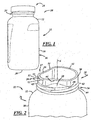
- FIG. 1 illustrates a package 20 including a container 22, and a closure 24 that is coupled to the container 22.
- the package 20 may be used to package pickles, baby food, salsa, peppers, spaghetti sauces, jams, or any other food products.
- the package 20 also may be used to package other types of products including but not limited to liquids, gels, powders, particles, and the like.
- the container 22 may be composed of glass, or any other material suitable for containing food products.
- the container 22 may be provided in any suitable sizes, and may be a wide mouth type of container.
- the container 22 includes a body 26 including a base 28, and a sidewall 30 extending in a direction axially away from the base 28.
- the body 26 also may include a shoulder 32 extending from the sidewall 30, as illustrated in the Figures. In other embodiments, however, the container body 26 need not include a shoulder.
- directional words such as top, bottom, upper, lower, radial, circumferential, lateral, longitudinal, transverse, vertical, horizontal, and the like are employed by way of description and not limitation.
- the container 22 also has a first, longitudinal axis A, and includes a neck finish 34 extending from the body 26. More particularly, the neck finish 34 may extend from the shoulder 32 of the sidewall 30. In other embodiments, however, where the container body 26 does not include a shoulder, the neck finish 34 may extend directly from the sidewall 30.
- the neck finish 34 includes a lower portion 36 and an upper portion 38 remote from the body 26 and extending from the lower portion 36.
- the lower portion 36 may be cylindrical, and the upper portion 38 is non-cylindrical.
- the lower portion 36 extends completely circumferentially around the neck finish 34, and has an outer surface 40 and one or more closure engagement features that may include lugs, bayonets, thread segments 42, or any other suitable features, on the outer surface 40.
- thread segment includes whole, partial, multiple, and/or an interrupted thread and/or thread segment.
- the thread segments 42 may include two, three, four, or any suitable quantity of thread segments 42. In any case, the thread segments 42 may extend completely circumferentially around the neck finish 34.
- the lower portion 36 also may include a capping flange 44 extending completely circumferentially around the neck finish 34 and disposed axially between the thread segments 42 and the body shoulder 32.
- the upper portion 38 includes indents or spout walls 46 disposed radially inwardly with respect to the lower portion 36 and laterally opposed from one another on either side of a second, radial axis B ( FIG. 5 ).
- the upper portion 38 also may include shoulders or ledges 48 disposed between the spout walls 46 formed as indents and the outer surface 40 of the lower portion 36.
- ledge generally includes a portion extending transversely to the axis A and adjacent to the higher, more prominent, spout walls 46.
- the upper portion 38 also may include a rear wall 50 extending between the spout walls 46 at rear ends of the spout walls 46.
- the rear wall 50 may be semi-circular or semi-cylindrical in shape and may be an extension of a corresponding portion of the lower portion 36 of the neck finish 34.
- the upper portion 38 further may include a trough wall 52 extending circumferentially between the spout walls 46 at forward ends of the spout walls 46, and disposed on an opposite side of a third, transverse radial axis C from the rear wall 50.
- the trough wall 52 also may be semi-circular or semi-cylindrical in shape and may extend axially from a corresponding part of the lower portion 36 of the neck finish 34.
- the trough wall 52 may include a lip or projection 51 and a recessed portion 53, for example, to aid in pouring contents from the container 22 in a clean or anti-drip manner.
- the projection 51 may extend from the sealing surface 54 in an axial direction toward the thread segments 42.
- the recessed portion 53 may be disposed axially between the projection 51 and the thread segment(s) 42, and the recessed portion 53 may be disposed radially inward of a radially outermost portion of the projection 51.
- a radially outer surface of the projection 51 may have the same radial dimension as a corresponding radially outer surface of the rear wall 50, whereas a radially outer surface of the recessed portion 53 may have a radial dimension that is smaller than the radially outer surfaces of the projection 51 and/or the rear wall 50.
- the rear and trough walls 50, 52 may be of any other suitable shapes.
- the spout walls 46 alone or together with other portions of the container 22 may form a pour spout 47.
- the walls 46, 50, 52 of the upper portion 38 of the neck finish 34 may terminate in a planar sealing surface 54. At least for the reason that the spout walls 46 may be disposed radially inwardly of the rear wall 50, the planar sealing surface 54 may be non-circular. In particular, the spout walls 46 may be incurvate with respect to the first axis A. Also, the upper portion 38 may be clamshell-shaped when viewed from above the upper portion 38 along the axis A.
- One or more of the thread segments 42 may be disposed in a circumferential overlapping relationship with the spout walls 46, the rear wall 50, and the trough wall 52. Accordingly, the securement of the closure 24 may be symmetrical, and uninterrupted or continuous, around the container 22.
- the container 22 may include an interior 56, a sidewall interior surface 58 of the body sidewall 30, a shoulder interior surface 60 of the body shoulder 32, a rear wall interior surface 62 of the neck finish 34 at a location corresponding to the rear wall 50, and a trough wall interior surface 64 of the neck finish 34 at a location corresponding to the trough wall 52.
- an inside diameter between the rear and trough walls 50, 52, or an inside radius of the interior surface 62 of the neck finish 34 may be greatest at the sealing surface 54 and may be smallest at the lower portion 36 ( FIG. 4 ).
- the radial wall thickness of the neck finish 34 at locations corresponding to the rear and trough walls 50, 52 may be the same and may be symmetrical.
- the container 22 also includes thickened wall portions 66.
- the thickened wall portions 66 correspond with the spout walls 46 and are circumferentially spaced apart. Also, the thickened wall portions 66 form an internal trough to direct flow of product toward the pour spout between the spout walls 46.
- the thickened wall portions 66 are disposed beneath the spout walls 46 or axially between the spout walls 46 and the base 28 of the container 22. Also, the thickened wall portions 66 are circumferentially aligned with the spout walls 46.
- the thickened wall portions 66 may extend from the neck finish 34 to the shoulder 32, and may also extend to the sidewall 30.
- the container 22 also includes interior surfaces 68 of the container neck finish 34 at locations corresponding to the spout walls 46.
- the thickened wall portions 66 may include those interior surfaces 68.
- the thickened wall portions 66 may form interior surfaces 58' of a thickened body sidewall portion 30' that are disposed radially inward of the interior surfaces 58 of the sidewall 30.
- the thickened wall portions 66 also may form interior surfaces 60' of a thickened body shoulder portion 32' that are disposed radially inward of the interior surfaces 60 of the shoulder 32.
- the thickened wall portions 66 extend radially inwardly, for example toward the axis A with respect to one or more of the interior surfaces 58, 60, 62, 64, to form an internal trough to direct flow of product toward the pour spout.
- FIGS. 11 through 13 illustrate another illustrative embodiment of a container 122. This embodiment is similar in many respects to the embodiments of FIGS. 1-10 and like numerals between the embodiments generally designate like or corresponding elements throughout the several views of the drawing figures. Accordingly, the descriptions of the embodiments are incorporated into one another. Additionally, the description of the common subject matter generally may not be repeated here.
- the container 122 includes a body 126 including a base 128, a sidewall 130 extending in a direction axially away from the base 128, and a shoulder 132.
- the container 122 also has a first, longitudinal axis A, and includes a neck finish 134 extending from the shoulder 132 of the body 126.
- the neck finish 134 may be the same as that described above with respect to FIGS. 1-10 and, thus, includes a pour spout 147 and may accept the closure 24 illustrated in FIG. 1 .
- the sidewall 130 includes a spout indicator 149 circumferentially corresponding to the pour spout 147, for instance, to indicate to a user the location of the pour spout 147 when a closure (not shown) applied to the container 122 obscures the circumferential orientation of the pour spout 147. Accordingly, when using the container 122, a user first may see the spout indicator 149 and then grip the container 122 in a suitable location and manner to enable the user to remove the closure and pour contents from the container 122 without having to adjust the user's grip to reorient the pour spout 147.
- the spout indicator 149 may be circumferentially aligned with the pour spout 147.
- the spout indicator 149 may be provided in any suitable manner.
- the spout indicator 149 may be formed from the same material as the rest of the sidewall 130. More specifically, the spout indicator 149 and the rest of the sidewall 130 may be formed of glass in a glass container manufacturing process. In other examples, the spout indicator 149 may be a separate component separately applied to the sidewall 130.
- the sidewall 130 may include a grip 155, for instance, to facilitate a good grip of the container 122 and further visually distinguish the spout indicator 149 so as to further enhance a user's ability to quickly spot the spout indicator 149 and begin using the container 122.
- the grip 155 may extend circumferentially partially around the body 126, may be indented or radially recessed, and may have circumferential ends 155a, 155b that may define or establish corresponding circumferential portions 149a, 149b of the spout indicator 149.
- the circumferential ends 155a, 155b of the grip 155 may be excurvate in a circumferential direction and the corresponding ends 149a, 149b of the indicator 149 may be incurvate in a circumferential direction, or vice-versa, or the ends may be straight or of any other suitable shape.
- the sidewall 130 may include a first portion 129 extending axially from the base 128 and a second portion 131 extending axially between the first portion 129 and the neck finish 134, wherein the second portion 131 may include the spout indicator 149 and the grip 155.
- the shoulder 132 may extend between the grip 155 and the neck finish 134.
- the first portion 129 may have a cylindrical outer surface that may be recessed as shown, for instance, to accept a product label, whereas the second portion 131 may have an outer surface that is incurvate in a radial direction, for instance for good gripping by a user.
- FIGS. 14 through 17 illustrate another illustrative embodiment of a container 222.
- This embodiment is similar in many respects to the embodiments of FIGS. 1-13 and like numerals between the embodiments generally designate like or corresponding elements throughout the several views of the drawing figures. Accordingly, the descriptions of the embodiments are incorporated into one another. Additionally, the description of the common subject matter generally may not be repeated here.
- the container 222 includes a body 226 including a base 228, a sidewall 230 extending from the base 228, and a shoulder 232 extending from the sidewall 230, as illustrated in the Figures.
- the container 222 also may include a neck finish 234 extending from the shoulder 232 of the sidewall 230 of the body 226.
- the sidewall 230 may include a spout indicator 249 circumferentially corresponding to the pour spout 247.
- the spout indicator 249 may be circumferentially aligned with the pour spout 247.
- the spout indicator 249 may be provided on the shoulder 232.
- the spout indicator 249 may be generally triangular, for instance, with radiused vertices, as illustrated.
- the spout indicator 249 may be of the same smooth surface finish as the rest of the body 226 or, as shown, may be textured to provide a surface finish that is coarser than rest of the body 226.
- the sidewall 230 also may include a circumferentially extending grip 255:
- the grip 255 may extend continuously, circumferentially, entirely around the container 222 and may be radially recessed.
- the grip 255 may be of the same smooth surface finish as the rest of the body 226 or, as shown, may be textured to provide a surface finish that is coarser than rest of the body 226.
- the grip 255 may be a relatively narrow band, for example, having a width or height less than one-quarter of the height of the body 226. In a more particular example, the height of the grip 255 may be less than one-inch.
- the grip 255 may be bordered by transitions between the outer surface of the sidewall 230 and the grip 255.
- the shape of the transitions may correspond to the shape of the grip 255 itself.
- the texture of the transitions may be the same as that of the sidewall 230 in general.
- the container 222 also includes thickened wall portions 266.
- the thickened wall portions 266 correspond with spout walls 246 and are circumferentially spaced apart to form an internal trough to direct flow of product toward the pour spout 247 between spout walls 246.
- the thickened wall portions 266 are similar to those described and shown in the previous embodiments, however, they may extend from the spout walls 246 into the neck finish 234 but do not extend below the shoulder 232 down along the sidewall 230 of the body 226. Otherwise, the thickened wall portions 266 may be identical to the previously described thickened wall portions 66.
- FIGS. 18 through 21 illustrate another illustrative embodiment of a container 322. This embodiment is similar in many respects to the embodiments of FIGS. 1-17 and like numerals between the embodiments generally designate like or corresponding elements throughout the several views of the drawing figures. Accordingly, the descriptions of the embodiments are incorporated into one another. Additionally, the description of the common subject matter generally may not be repeated here.
- the container 322 includes a body 326 including a base 328, a sidewall 330 extending from the base 328, and a shoulder 332 extending from the sidewall 330, as illustrated in the Figures.
- the container 322 also includes a neck finish 334 extending from the shoulder 332 of the sidewall 330 of the body 326.
- the sidewall 330 may include the spout indicator 249 described above with respect to FIGS. 14-17 .
- the sidewall 330 may include a grip, which may include multiple grip portions, for example, two discrete or individual grip portions 355a, 355b.
- the grip portions 355a, 355b may be disposed on opposite sides of the container body 326, for instance, diametrically opposed from one another on either side of radial axis B as best shown in FIGS. 19 and 20 .
- the grip portions 355a, 355b may be of the same smooth surface finish as the rest of the body 326 or, as shown, may be textured to provide a surface finish that is coarser than rest of the body 326.
- the grip portions 355a, 355b may be generally oval-shaped, for instance, egg-shaped, ellipse-shaped, oblong, or the like, and/or may correspond to an index finger placement and a thumb placement.
- the grip portions 355a, 355b may be bordered by transitions 357a, 357b between the outer surface of the sidewall 330 and the grip portions 355a, 355b.
- the shape of the transitions 357a, 357b may correspond to the shape of the grip portions 355a, 355b.
- the texture of the transitions 357a, 357b may be the same as that of the sidewall 330 in general.
- the sidewall 330 may have an outer surface portion 329 that may be recessed as shown, for instance, to accept a product label.
- the grip portions 355a, 355b may be provided in the recessed portion 329.
Landscapes
- Engineering & Computer Science (AREA)
- Mechanical Engineering (AREA)
- Ceramic Engineering (AREA)
- Closures For Containers (AREA)
- Containers Having Bodies Formed In One Piece (AREA)
- Details Of Rigid Or Semi-Rigid Containers (AREA)
- Packages (AREA)
Description
- The present disclosure is directed to containers and, more particularly, to a container with a pour spout.
- Containers often include a body and a neck finish extending axially from the body to accept a closure. The body usually includes a base, a sidewall extending axially away from the base, and a shoulder between the sidewall and the neck finish. The neck finish typically includes circumferentially extending threads or lugs to cooperate with corresponding features of the closure.
U.S. Patents that illustrate glass containers of this type include 2,688,823 and3,738,524 .US 2007/0235477 discloses a container according to the preamble ofclaim 1.US 2059910 discloses a through for pouring in a bottle mouth. - A general object of the present disclosure, in accordance with one aspect of the disclosure, is to provide a container having a pour spout to direct flow of product through the pour spout and out of the container.
- The present disclosure embodies a number of aspects that can be implemented separately from or in combination with each other.
- A container in accordance with one aspect of the disclosure includes a body and a neck finish for securement of a closure, the neck finish including a lower portion adjacent to the body, and a non-cylindrical portion remote from the body with laterally opposed indents forming a pour spout.
- The disclosure, together with additional objects, features, advantages and aspects thereof, will be best understood from the following description, the appended claims and the accompanying drawings, in which:
-
FIG. 1 is an elevational view of a package including a container and a closure in accordance with an illustrative embodiment of the present disclosure; -
FIG. 2 is an enlarged fragmentary perspective view of the container ofFIG. 1 ; -
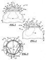
FIG. 3 is an enlarged fragmentary front view of the container ofFIG. 1 ; -
FIG. 4 is an enlarged fragmentary side view of the container ofFIG. 1 ; -
FIG. 5 is an enlarged top view of the container ofFIG. 1 ; -
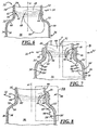
FIG. 6 is a fragmentary sectional view of the container ofFIG. 1 , taken substantially along line 6-6 ofFIG. 5 ; -
FIG. 7 is a fragmentary sectional view of the container ofFIG. 1 , taken substantially along line 7-7 ofFIG. 5 ; -
FIG. 8 is a fragmentary sectional view of the container ofFIG. 1 , taken substantially along line 8-8 ofFIG. 5 ; -
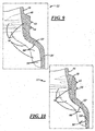
FIG. 9 is an enlarged fragmentary sectional view of a portion of the container ofFIG. 1 , taken from box 9 ofFIG. 7 ; -
FIG. 10 is an enlarged fragmentary sectional view of a portion of the container ofFIG. 1 , taken frombox 10 ofFIG. 8 ; -
FIG. 11 is a perspective view of a container in accordance with another illustrative embodiment of the present disclosure; -
FIG. 12 is a side view of the container ofFIG. 11 ; -
FIG. 13 is a front view of the container ofFIG. 11 ; -
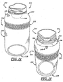
FIG. 14 is a side perspective view of a container in accordance with a further illustrative embodiment of the present disclosure; -
FIG. 15 is a front perspective view of the container ofFIG. 14 ; -
FIG. 16 is an enlarged fragmentary front view of the container ofFIG. 14 ; -
FIG. 17 is a fragmentary sectional view of the container ofFIG. 14 ; -
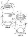
FIG. 18 is a side perspective view of a container in accordance with an additional illustrative embodiment of the present disclosure; -
FIG. 19 is a front perspective view of the container ofFIG. 18 ; -
FIG. 20 is a front view of the container ofFIG. 18 ; and -
FIG. 21 is a side view of the container ofFIG. 18 . -
FIG. 1 illustrates apackage 20 including acontainer 22, and aclosure 24 that is coupled to thecontainer 22. Thepackage 20 may be used to package pickles, baby food, salsa, peppers, spaghetti sauces, jams, or any other food products. Thepackage 20 also may be used to package other types of products including but not limited to liquids, gels, powders, particles, and the like. - The
container 22 may be composed of glass, or any other material suitable for containing food products. Thecontainer 22 may be provided in any suitable sizes, and may be a wide mouth type of container. Thecontainer 22 includes abody 26 including abase 28, and asidewall 30 extending in a direction axially away from thebase 28. Thebody 26 also may include ashoulder 32 extending from thesidewall 30, as illustrated in the Figures. In other embodiments, however, thecontainer body 26 need not include a shoulder. As used herein, directional words such as top, bottom, upper, lower, radial, circumferential, lateral, longitudinal, transverse, vertical, horizontal, and the like are employed by way of description and not limitation. - Referring to
FIGS. 2 through 4 , thecontainer 22 also has a first, longitudinal axis A, and includes aneck finish 34 extending from thebody 26. More particularly, theneck finish 34 may extend from theshoulder 32 of thesidewall 30. In other embodiments, however, where thecontainer body 26 does not include a shoulder, theneck finish 34 may extend directly from thesidewall 30. Theneck finish 34 includes alower portion 36 and anupper portion 38 remote from thebody 26 and extending from thelower portion 36. Thelower portion 36 may be cylindrical, and theupper portion 38 is non-cylindrical. - The
lower portion 36 extends completely circumferentially around theneck finish 34, and has anouter surface 40 and one or more closure engagement features that may include lugs, bayonets,thread segments 42, or any other suitable features, on theouter surface 40. As used herein, the term thread segment includes whole, partial, multiple, and/or an interrupted thread and/or thread segment. Thethread segments 42 may include two, three, four, or any suitable quantity ofthread segments 42. In any case, thethread segments 42 may extend completely circumferentially around theneck finish 34. Thelower portion 36 also may include acapping flange 44 extending completely circumferentially around theneck finish 34 and disposed axially between thethread segments 42 and thebody shoulder 32. - The
upper portion 38 includes indents orspout walls 46 disposed radially inwardly with respect to thelower portion 36 and laterally opposed from one another on either side of a second, radial axis B (FIG. 5 ). Theupper portion 38 also may include shoulders orledges 48 disposed between thespout walls 46 formed as indents and theouter surface 40 of thelower portion 36. As used herein the term "ledge" generally includes a portion extending transversely to the axis A and adjacent to the higher, more prominent,spout walls 46. - The
upper portion 38 also may include arear wall 50 extending between thespout walls 46 at rear ends of thespout walls 46. Therear wall 50 may be semi-circular or semi-cylindrical in shape and may be an extension of a corresponding portion of thelower portion 36 of theneck finish 34. - The
upper portion 38 further may include atrough wall 52 extending circumferentially between thespout walls 46 at forward ends of thespout walls 46, and disposed on an opposite side of a third, transverse radial axis C from therear wall 50. Thetrough wall 52 also may be semi-circular or semi-cylindrical in shape and may extend axially from a corresponding part of thelower portion 36 of theneck finish 34. Thetrough wall 52 may include a lip orprojection 51 and arecessed portion 53, for example, to aid in pouring contents from thecontainer 22 in a clean or anti-drip manner. Theprojection 51 may extend from thesealing surface 54 in an axial direction toward thethread segments 42. Therecessed portion 53 may be disposed axially between theprojection 51 and the thread segment(s) 42, and therecessed portion 53 may be disposed radially inward of a radially outermost portion of theprojection 51. For example, a radially outer surface of theprojection 51 may have the same radial dimension as a corresponding radially outer surface of therear wall 50, whereas a radially outer surface of therecessed portion 53 may have a radial dimension that is smaller than the radially outer surfaces of theprojection 51 and/or therear wall 50. - In other embodiments, the rear and
trough walls spout walls 46 alone or together with other portions of the container 22 (e.g. the trough wall 52) may form a pourspout 47. - The
walls upper portion 38 of theneck finish 34 may terminate in aplanar sealing surface 54. At least for the reason that thespout walls 46 may be disposed radially inwardly of therear wall 50, theplanar sealing surface 54 may be non-circular. In particular, thespout walls 46 may be incurvate with respect to the first axis A. Also, theupper portion 38 may be clamshell-shaped when viewed from above theupper portion 38 along the axis A. - One or more of the
thread segments 42 may be disposed in a circumferential overlapping relationship with thespout walls 46, therear wall 50, and thetrough wall 52. Accordingly, the securement of theclosure 24 may be symmetrical, and uninterrupted or continuous, around thecontainer 22. - Referring to
FIG. 6 , thecontainer 22 may include an interior 56, a sidewallinterior surface 58 of thebody sidewall 30, a shoulderinterior surface 60 of thebody shoulder 32, a rear wall interior surface 62 of theneck finish 34 at a location corresponding to therear wall 50, and a trough wallinterior surface 64 of theneck finish 34 at a location corresponding to thetrough wall 52. As shown inFIG. 6 , an inside diameter between the rear andtrough walls neck finish 34, may be greatest at the sealingsurface 54 and may be smallest at the lower portion 36 (FIG. 4 ). Also as shown inFIG. 6 , the radial wall thickness of theneck finish 34 at locations corresponding to the rear andtrough walls - Referring to
FIGS. 7-10 , thecontainer 22 also includes thickenedwall portions 66. The thickenedwall portions 66 correspond with thespout walls 46 and are circumferentially spaced apart. Also, the thickenedwall portions 66 form an internal trough to direct flow of product toward the pour spout between thespout walls 46. The thickenedwall portions 66 are disposed beneath thespout walls 46 or axially between thespout walls 46 and thebase 28 of thecontainer 22. Also, the thickenedwall portions 66 are circumferentially aligned with thespout walls 46. The thickenedwall portions 66 may extend from theneck finish 34 to theshoulder 32, and may also extend to thesidewall 30. - The
container 22 also includesinterior surfaces 68 of thecontainer neck finish 34 at locations corresponding to thespout walls 46. The thickenedwall portions 66 may include those interior surfaces 68. In addition, the thickenedwall portions 66 may form interior surfaces 58' of a thickened body sidewall portion 30' that are disposed radially inward of the interior surfaces 58 of thesidewall 30. The thickenedwall portions 66 also may form interior surfaces 60' of a thickened body shoulder portion 32' that are disposed radially inward of the interior surfaces 60 of theshoulder 32. In any case, the thickenedwall portions 66 extend radially inwardly, for example toward the axis A with respect to one or more of the interior surfaces 58, 60, 62, 64, to form an internal trough to direct flow of product toward the pour spout. -
FIGS. 11 through 13 illustrate another illustrative embodiment of acontainer 122. This embodiment is similar in many respects to the embodiments ofFIGS. 1-10 and like numerals between the embodiments generally designate like or corresponding elements throughout the several views of the drawing figures. Accordingly, the descriptions of the embodiments are incorporated into one another. Additionally, the description of the common subject matter generally may not be repeated here. - The
container 122 includes abody 126 including abase 128, asidewall 130 extending in a direction axially away from thebase 128, and ashoulder 132. Thecontainer 122 also has a first, longitudinal axis A, and includes aneck finish 134 extending from theshoulder 132 of thebody 126. Theneck finish 134 may be the same as that described above with respect toFIGS. 1-10 and, thus, includes a pourspout 147 and may accept theclosure 24 illustrated inFIG. 1 . - The
sidewall 130 includes aspout indicator 149 circumferentially corresponding to the pourspout 147, for instance, to indicate to a user the location of the pourspout 147 when a closure (not shown) applied to thecontainer 122 obscures the circumferential orientation of the pourspout 147. Accordingly, when using thecontainer 122, a user first may see thespout indicator 149 and then grip thecontainer 122 in a suitable location and manner to enable the user to remove the closure and pour contents from thecontainer 122 without having to adjust the user's grip to reorient the pourspout 147. Thespout indicator 149 may be circumferentially aligned with the pourspout 147. - The
spout indicator 149 may be provided in any suitable manner. For example, thespout indicator 149 may be formed from the same material as the rest of thesidewall 130. More specifically, thespout indicator 149 and the rest of thesidewall 130 may be formed of glass in a glass container manufacturing process. In other examples, thespout indicator 149 may be a separate component separately applied to thesidewall 130. - Referring to
FIG. 13 , thesidewall 130 may include agrip 155, for instance, to facilitate a good grip of thecontainer 122 and further visually distinguish thespout indicator 149 so as to further enhance a user's ability to quickly spot thespout indicator 149 and begin using thecontainer 122. Thegrip 155 may extend circumferentially partially around thebody 126, may be indented or radially recessed, and may have circumferential ends 155a, 155b that may define or establish correspondingcircumferential portions spout indicator 149. The circumferential ends 155a, 155b of thegrip 155 may be excurvate in a circumferential direction and the corresponding ends 149a, 149b of theindicator 149 may be incurvate in a circumferential direction, or vice-versa, or the ends may be straight or of any other suitable shape. - In the embodiment of
FIGS. 11-13 , thesidewall 130 may include afirst portion 129 extending axially from thebase 128 and asecond portion 131 extending axially between thefirst portion 129 and theneck finish 134, wherein thesecond portion 131 may include thespout indicator 149 and thegrip 155. Theshoulder 132 may extend between thegrip 155 and theneck finish 134. Also, thefirst portion 129 may have a cylindrical outer surface that may be recessed as shown, for instance, to accept a product label, whereas thesecond portion 131 may have an outer surface that is incurvate in a radial direction, for instance for good gripping by a user. -
FIGS. 14 through 17 illustrate another illustrative embodiment of acontainer 222. This embodiment is similar in many respects to the embodiments ofFIGS. 1-13 and like numerals between the embodiments generally designate like or corresponding elements throughout the several views of the drawing figures. Accordingly, the descriptions of the embodiments are incorporated into one another. Additionally, the description of the common subject matter generally may not be repeated here. - With reference to
FIGS. 14 and 15 , thecontainer 222 includes abody 226 including abase 228, asidewall 230 extending from thebase 228, and ashoulder 232 extending from thesidewall 230, as illustrated in the Figures. Thecontainer 222 also may include aneck finish 234 extending from theshoulder 232 of thesidewall 230 of thebody 226. - The
sidewall 230 may include aspout indicator 249 circumferentially corresponding to the pourspout 247. For example, as best shown inFIG. 15 , thespout indicator 249 may be circumferentially aligned with the pourspout 247. Also, thespout indicator 249 may be provided on theshoulder 232. Thespout indicator 249 may be generally triangular, for instance, with radiused vertices, as illustrated. Thespout indicator 249 may be of the same smooth surface finish as the rest of thebody 226 or, as shown, may be textured to provide a surface finish that is coarser than rest of thebody 226. - The
sidewall 230 also may include a circumferentially extending grip 255: Thegrip 255 may extend continuously, circumferentially, entirely around thecontainer 222 and may be radially recessed. Thegrip 255 may be of the same smooth surface finish as the rest of thebody 226 or, as shown, may be textured to provide a surface finish that is coarser than rest of thebody 226. Thegrip 255 may be a relatively narrow band, for example, having a width or height less than one-quarter of the height of thebody 226. In a more particular example, the height of thegrip 255 may be less than one-inch. - As shown in
FIGS..14 and 15 , thegrip 255 may be bordered by transitions between the outer surface of thesidewall 230 and thegrip 255. The shape of the transitions may correspond to the shape of thegrip 255 itself. The texture of the transitions may be the same as that of thesidewall 230 in general. - With reference also to
FIGS. 16 and 17 , thecontainer 222 also includes thickenedwall portions 266. The thickenedwall portions 266 correspond withspout walls 246 and are circumferentially spaced apart to form an internal trough to direct flow of product toward the pourspout 247 betweenspout walls 246. The thickenedwall portions 266 are similar to those described and shown in the previous embodiments, however, they may extend from thespout walls 246 into theneck finish 234 but do not extend below theshoulder 232 down along thesidewall 230 of thebody 226. Otherwise, the thickenedwall portions 266 may be identical to the previously described thickenedwall portions 66. -
FIGS. 18 through 21 illustrate another illustrative embodiment of acontainer 322. This embodiment is similar in many respects to the embodiments ofFIGS. 1-17 and like numerals between the embodiments generally designate like or corresponding elements throughout the several views of the drawing figures. Accordingly, the descriptions of the embodiments are incorporated into one another. Additionally, the description of the common subject matter generally may not be repeated here. - With reference to
FIGS. 18 and 19 , thecontainer 322 includes abody 326 including abase 328, asidewall 330 extending from thebase 328, and ashoulder 332 extending from thesidewall 330, as illustrated in the Figures. Thecontainer 322 also includes aneck finish 334 extending from theshoulder 332 of thesidewall 330 of thebody 326. Thesidewall 330 may include thespout indicator 249 described above with respect toFIGS. 14-17 . - Also, the
sidewall 330 may include a grip, which may include multiple grip portions, for example, two discrete orindividual grip portions grip portions container body 326, for instance, diametrically opposed from one another on either side of radial axis B as best shown inFIGS. 19 and20 . Thegrip portions body 326 or, as shown, may be textured to provide a surface finish that is coarser than rest of thebody 326. Thegrip portions grip portions transitions sidewall 330 and thegrip portions transitions grip portions transitions sidewall 330 in general. - The
sidewall 330 may have anouter surface portion 329 that may be recessed as shown, for instance, to accept a product label. Thegrip portions portion 329. - There thus has been disclosed containers that may provide improved product flow and that fully satisfies all of the objects and aims previously set forth. The disclosure has been presented in conjunction with several illustrative embodiments, and additional modifications and variations have been discussed. Other modifications and variations readily will suggest themselves to persons of ordinary skill in the art in view of the foregoing discussion.
Claims (14)
- A container (22, 122, 222, 322) having a body (26, 126, 226, 326) and a neck finish (34, 134, 234, 334) for securement of a closure, said neck finish (34, 134, 234, 334) including a lower portion (36) adjacent to said body (26, 126, 226, 326), and a non-cylindrical upper portion (38) remote from said body (26, 126, 226, 326) with laterally opposed indents (46, 246) forming a pour spout (47, 147, 247),
characterized in that
said lower portion (36) of said neck finish (34, 134, 234, 334) is thicker axially beneath said indents (46, 246) than circumferentially spaced from said indents (46, 246), said thicker lower portion enhancing operation of said pour spout (47, 147, 247). - The container (22, 122, 222, 322) set forth in claim 1 wherein said lower portion (36) includes a cylindrical outer surface and at least one closure engagement feature (42).
- The container (22, 122, 222, 322) set forth in claim 1 wherein said body (26, 126, 226, 326) includes a base (28, 128, 228, 328); a sidewall extending from said base (28, 128, 228, 328), and a shoulder (32, 132, 232, 332) adjacent to said neck finish (34, 134, 234, 334), and wherein said thicker lower portion extends into said shoulder (32, 132, 232, 332) of said container (22, 122, 222, 322).
- The container (22, 122, 222, 322) set forth in claim 1 wherein said body (26, 125, 226, 326) includes a base (28, 128, 228, 328) and a sidewall extending from said base (28, 128, 228, 328), and wherein said thicker lower portion extends down along interior surfaces of said sidewall of said container (22, 122, 222, 322).
- The container (22, 122, 222, 322) set forth in claim 1 wherein said upper portion (38) of said neck finish (34, 134, 234, 334) has a planar non-circular sealing surface remote from said body (26, 126, 226, 326).
- The container (22, 122, 222, 322) set forth in claim 2 wherein said spout (47, 147, 247) includes said indents (46, 246), and said non-cylindrical upper portion (38) includes a trough wall (52) which extends circumferentially between ends of said indents (46, 246), extends axially from a corresponding part of said lower portion (36) of said neck finish (34, 134, 234, 334), and includes a projection (51) and a recessed portion (53) disposed axially between said projection (51) and said at least one closure engagement feature (42) and radially inward with respect to said projection (51).
- The container (22, 122) set forth in claim 1 wherein said body (126, 226) includes a spout indicator (149, 249) circumferentially corresponding to said pour spout (147, 247).
- The container (22, 122) set forth in claim 7 wherein said spout indicator (149, 249) is circumferential ly aligned with said pour spout (147, 247).
- The container (222) set forth in claim 7 wherein said body (226) includes a sidewall, and a shoulder (232) from which said neck finish (234) extends, and wherein said spout indicator (249) is on said shoulder (232).
- The container (222) set forth in claim 7 wherein said spout indicator (249) is triangular,
- The container (222) set forth in claim 7 wherein said spout indicator (249) is textured to provide a surface finish that is coarser than the rest of said body (226).
- The container (122) set forth in claim 1 wherein said body (126) includes a grip (155) that is radially recessed, extends circumferentially partially around said body (126), and has circumferential ends (155a, 155b) establishing a spout indicator (149).
- The container (122) set forth in claim 12 wherein said grip (155) is textured to provide a surface finish coarser than that of the rest of the body (126).
- The container (122, 222) set forth in claim 1 wherein said sidewall of said body (126, 226) has a recessed outer surface portion (155, 255), and grip portions are provided in said recessed outer surface portion.
Priority Applications (5)
| Application Number | Priority Date | Filing Date | Title |
|---|---|---|---|
| DK16189195.7T DK3124389T3 (en) | 2011-10-28 | 2012-08-30 | CONTAINER WITH PILLOW SPOIL. |
| PL16189195T PL3124389T3 (en) | 2011-10-28 | 2012-08-30 | Container with pouring spout |
| HRP20161683TT HRP20161683T1 (en) | 2011-10-28 | 2012-08-30 | SPLIT TANK |
| EP16189195.7A EP3124389B1 (en) | 2011-10-28 | 2012-08-30 | Container with pour spout |
| PL12767144T PL2771246T3 (en) | 2011-10-28 | 2012-08-30 | Container with pour spout |
Applications Claiming Priority (2)
| Application Number | Priority Date | Filing Date | Title |
|---|---|---|---|
| US13/284,520 US9108757B2 (en) | 2011-10-28 | 2011-10-28 | Container with pour spout |
| PCT/US2012/053075 WO2013062671A1 (en) | 2011-10-28 | 2012-08-30 | Container with pour spout |
Related Child Applications (2)
| Application Number | Title | Priority Date | Filing Date |
|---|---|---|---|
| EP16189195.7A Division-Into EP3124389B1 (en) | 2011-10-28 | 2012-08-30 | Container with pour spout |
| EP16189195.7A Division EP3124389B1 (en) | 2011-10-28 | 2012-08-30 | Container with pour spout |
Publications (2)
| Publication Number | Publication Date |
|---|---|
| EP2771246A1 EP2771246A1 (en) | 2014-09-03 |
| EP2771246B1 true EP2771246B1 (en) | 2016-11-02 |
Family
ID=46968356
Family Applications (2)
| Application Number | Title | Priority Date | Filing Date |
|---|---|---|---|
| EP16189195.7A Active EP3124389B1 (en) | 2011-10-28 | 2012-08-30 | Container with pour spout |
| EP12767144.4A Active EP2771246B1 (en) | 2011-10-28 | 2012-08-30 | Container with pour spout |
Family Applications Before (1)
| Application Number | Title | Priority Date | Filing Date |
|---|---|---|---|
| EP16189195.7A Active EP3124389B1 (en) | 2011-10-28 | 2012-08-30 | Container with pour spout |
Country Status (26)
| Country | Link |
|---|---|
| US (1) | US9108757B2 (en) |
| EP (2) | EP3124389B1 (en) |
| CN (1) | CN103889844B (en) |
| AR (1) | AR088506A1 (en) |
| AU (1) | AU2012329370B2 (en) |
| BR (2) | BR112014010121B1 (en) |
| CA (1) | CA2850420C (en) |
| CL (1) | CL2014001067A1 (en) |
| CO (1) | CO6930335A2 (en) |
| DK (2) | DK3124389T3 (en) |
| EC (1) | ECSP14013321A (en) |
| ES (2) | ES2614002T3 (en) |
| HR (2) | HRP20161683T1 (en) |
| HU (2) | HUE031560T2 (en) |
| MX (1) | MX346978B (en) |
| MY (1) | MY164139A (en) |
| PE (1) | PE20141422A1 (en) |
| PH (1) | PH12014500792A1 (en) |
| PL (2) | PL2771246T3 (en) |
| PT (2) | PT2771246T (en) |
| RU (1) | RU2014121495A (en) |
| SG (1) | SG11201401840SA (en) |
| TR (1) | TR201902610T4 (en) |
| TW (1) | TW201332849A (en) |
| WO (1) | WO2013062671A1 (en) |
| ZA (1) | ZA201402291B (en) |
Families Citing this family (15)
| Publication number | Priority date | Publication date | Assignee | Title |
|---|---|---|---|---|
| US9656772B2 (en) | 2011-10-28 | 2017-05-23 | Owens-Brockway Glass Container Inc. | Container with pour spout |
| USD698646S1 (en) | 2011-10-28 | 2014-02-04 | Owens-Brockway Glass Container Inc. | Container |
| USD713252S1 (en) | 2012-04-11 | 2014-09-16 | Owens-Brockway Glass Container Inc. | Container finish |
| CA2911091C (en) * | 2013-05-01 | 2021-01-12 | Owens-Brockway Glass Container Inc. | Container with pour spout |
| USD725473S1 (en) | 2013-12-06 | 2015-03-31 | Owens-Brockway Glass Container Inc. | Container |
| GB2526347B (en) * | 2014-05-22 | 2019-05-29 | Rpc Group Plc | Container |
| USD762323S1 (en) * | 2015-02-12 | 2016-07-26 | Bocci Design and Manufacturing Inc. | Glass pendant for decorative light fixtures |
| USD754911S1 (en) * | 2015-03-05 | 2016-04-26 | Bocci Design and Manufacturing Inc | Glass pendant for decorative light fixtures |
| CA3014532C (en) * | 2016-02-12 | 2020-12-15 | The Sherwin-Williams Company | Storage container |
| EP3532392A1 (en) * | 2016-10-31 | 2019-09-04 | Graham Packaging Company, L.P. | Plastic container with integrated spout for directional pour |
| US11203457B2 (en) | 2018-11-09 | 2021-12-21 | Graham Packaging Company, L.P. | Blow molded plastic container with integrated spout |
| TWI769716B (en) * | 2021-02-25 | 2022-07-01 | 聯華食品工業股份有限公司 | Food container filling kit and filling method thereof |
| US11794938B2 (en) * | 2021-09-02 | 2023-10-24 | Graham Packaging Company, L.P. | Container finish having improved rim planarity |
| JP7814821B2 (en) * | 2022-10-31 | 2026-02-17 | 株式会社吉野工業所 | Refill containers and preforms |
| US20250042595A1 (en) * | 2023-08-04 | 2025-02-06 | Canon Kabushiki Kaisha | Liquid storage bottle |
Citations (1)
| Publication number | Priority date | Publication date | Assignee | Title |
|---|---|---|---|---|
| US2059910A (en) * | 1935-12-26 | 1936-11-03 | Abbott Lab | Bottle finish |
Family Cites Families (47)
| Publication number | Priority date | Publication date | Assignee | Title |
|---|---|---|---|---|
| USRE20427E (en) | 1937-06-29 | Container | ||
| US507410A (en) * | 1893-10-24 | Thirds to hugh h | ||
| US1108023A (en) | 1913-12-16 | 1914-08-18 | Charles H Texter | Milk-bottle. |
| US1421696A (en) * | 1921-07-12 | 1922-07-04 | Capstan Glass Co | Pitcher, tumbler, and package |
| US1814659A (en) | 1929-01-21 | 1931-07-14 | Henry Barroll & Co Inc | Pouring nozzle |
| US1925913A (en) * | 1932-08-20 | 1933-09-05 | Robert F Kerkam | Drip preventing means |
| US2039345A (en) * | 1932-10-31 | 1936-05-05 | Edward A Ravenscroft | Bottle mouth |
| US2035877A (en) * | 1933-01-18 | 1936-03-31 | Gerald K Geerlings | Container |
| US2057745A (en) * | 1934-04-24 | 1936-10-20 | Scheyer Sophie | Liquid container |
| US2075776A (en) | 1935-03-06 | 1937-03-30 | Owens Illinois Glass Co | Container |
| US2099043A (en) * | 1936-08-03 | 1937-11-16 | Raymond R Wicklein | Crucible |
| US2135330A (en) | 1937-02-01 | 1938-11-01 | Owens Illinois Glass Co | Dispensing container |
| US2428588A (en) * | 1943-07-07 | 1947-10-07 | Harry E Schroeder | Jar or container |
| US2521523A (en) * | 1945-05-26 | 1950-09-05 | Robert J Kemper | Dripless pouring device |
| US2688823A (en) | 1950-11-20 | 1954-09-14 | Owens Illinois Glass Co | Method and apparatus for forming glass parisons |
| US3022916A (en) | 1960-09-08 | 1962-02-27 | Spooner Daniel | Containers or jars |
| US3235111A (en) | 1964-04-07 | 1966-02-15 | American Hospital Supply Corp | Container |
| US3400846A (en) * | 1966-08-31 | 1968-09-10 | Haskon Inc | Container construction |
| US3391838A (en) * | 1967-02-06 | 1968-07-09 | George L. Gundel | Container having anti-drip means |
| US3537498A (en) * | 1968-10-14 | 1970-11-03 | American Hospital Supply Corp | Thermoplastic bottle for sterile medical liquids |
| US3700146A (en) * | 1970-03-25 | 1972-10-24 | Gen Foods Corp | Cup with pour spout and circular finish |
| US3738524A (en) | 1971-03-31 | 1973-06-12 | Owens Illinois Inc | Plastic covered glass container |
| US4630761A (en) * | 1984-03-12 | 1986-12-23 | Little Rapids Corp. | Container with pouring spout and removable cover |
| US5065908A (en) * | 1991-01-16 | 1991-11-19 | Continental Plastics, Inc. | Dispensing fitment and container therefore |
| AU1339792A (en) * | 1991-01-17 | 1992-08-27 | Get A Gripp Ii, Inc. | Beverage bottle with grip |
| ES2090578T3 (en) * | 1991-12-12 | 1996-10-16 | Tetra Laval Holdings & Finance | CLOSING CAPSULE. |
| USD391159S (en) * | 1996-04-29 | 1998-02-24 | Vincent T. Brady | Molded bottle having integral pouring spout |
| US5964383A (en) | 1997-04-22 | 1999-10-12 | Graham Packaging Company, L.P. | Pinch neck pour spout container |
| US5988460A (en) * | 1998-03-30 | 1999-11-23 | Owens-Brockway Plastic Products Inc. | Molded plastic container and container package with integral pour spout |
| US6085949A (en) | 1998-05-05 | 2000-07-11 | Liquid Container L.P. | Container with molded-in directional pour guide |
| US6059153A (en) * | 1998-10-09 | 2000-05-09 | Kraft Foods, Inc. | Container for pourable food products |
| FR2797251B1 (en) * | 1999-08-06 | 2001-10-12 | Sidel Sa | PLASTIC BOTTLE HAVING REINFORCEMENT MEANS |
| ATE404446T1 (en) * | 2001-04-18 | 2008-08-15 | Sherwin Williams Co | IMPROVED CONTAINER AND LID ARRANGEMENT |
| US7036693B2 (en) * | 2001-12-05 | 2006-05-02 | Masterchem Industries Llc | Paint container |
| US6609638B1 (en) * | 2002-07-22 | 2003-08-26 | W. Gerald Lott | Flow promoter for hoppers |
| US6814248B2 (en) * | 2002-08-08 | 2004-11-09 | Dtl Technology Limited Partnership | Plastics container with recessed handgrip features and associated method and apparatus for manufacture thereof |
| KR100587537B1 (en) | 2003-01-24 | 2006-06-13 | 문광열 | Beverage container |
| US6994233B2 (en) * | 2003-07-16 | 2006-02-07 | Ring Container Technologies, Inc. | Vented plastic bottle |
| AR048477A1 (en) * | 2004-11-19 | 2006-05-03 | Alusud Argentina S R L | PICO VERTEDOR OF THE TYPE EMPLOYED IN BOTTLES CONTAINERS OF LIQUID SUBSTANCES WITH VARIABLE VISCOSITY DEGREE |
| US20070210123A1 (en) * | 2006-03-07 | 2007-09-13 | Penny Michael E | Container having blown pour spout |
| US20070235477A1 (en) * | 2006-04-11 | 2007-10-11 | Penny Michael E | Container having blown pour spout |
| US7870979B2 (en) * | 2006-04-13 | 2011-01-18 | The Quaker Oats Company | Container with a scoopable and pourable spout |
| US7770745B2 (en) | 2006-06-19 | 2010-08-10 | Amcor Limited | Wide mouth jar with integral scraper |
| AU2008201002A1 (en) | 2007-03-20 | 2008-10-09 | Henry Enahoro | Vessel |
| US8567625B2 (en) * | 2007-08-31 | 2013-10-29 | Toyo Seikan Kaisha, Ltd. | Synthetic resin container having a rectangular cylindrical part and a round cylindrical narrow part |
| US20100181278A1 (en) | 2008-12-12 | 2010-07-22 | Martin Steven W | Free flowing bottle |
| US8714417B1 (en) * | 2010-11-09 | 2014-05-06 | Plastek Industries, Inc. | Injection molded jar with pour feature |
-
2011
- 2011-10-28 US US13/284,520 patent/US9108757B2/en active Active
-
2012
- 2012-08-30 CN CN201280052984.7A patent/CN103889844B/en active Active
- 2012-08-30 SG SG11201401840SA patent/SG11201401840SA/en unknown
- 2012-08-30 HU HUE12767144A patent/HUE031560T2/en unknown
- 2012-08-30 ES ES12767144.4T patent/ES2614002T3/en active Active
- 2012-08-30 HR HRP20161683TT patent/HRP20161683T1/en unknown
- 2012-08-30 HU HUE16189195A patent/HUE043315T2/en unknown
- 2012-08-30 EP EP16189195.7A patent/EP3124389B1/en active Active
- 2012-08-30 TR TR2019/02610T patent/TR201902610T4/en unknown
- 2012-08-30 PL PL12767144T patent/PL2771246T3/en unknown
- 2012-08-30 MY MYPI2014000831A patent/MY164139A/en unknown
- 2012-08-30 PL PL16189195T patent/PL3124389T3/en unknown
- 2012-08-30 EP EP12767144.4A patent/EP2771246B1/en active Active
- 2012-08-30 DK DK16189195.7T patent/DK3124389T3/en active
- 2012-08-30 AU AU2012329370A patent/AU2012329370B2/en active Active
- 2012-08-30 PH PH1/2014/500792A patent/PH12014500792A1/en unknown
- 2012-08-30 PT PT127671444T patent/PT2771246T/en unknown
- 2012-08-30 ES ES16189195T patent/ES2726284T3/en active Active
- 2012-08-30 PE PE2014000610A patent/PE20141422A1/en active IP Right Grant
- 2012-08-30 DK DK12767144.4T patent/DK2771246T3/en active
- 2012-08-30 PT PT16189195T patent/PT3124389T/en unknown
- 2012-08-30 RU RU2014121495/12A patent/RU2014121495A/en not_active Application Discontinuation
- 2012-08-30 BR BR112014010121-3A patent/BR112014010121B1/en active IP Right Grant
- 2012-08-30 BR BR122019024697-1A patent/BR122019024697B1/en active IP Right Grant
- 2012-08-30 MX MX2014004584A patent/MX346978B/en active IP Right Grant
- 2012-08-30 WO PCT/US2012/053075 patent/WO2013062671A1/en not_active Ceased
- 2012-08-30 CA CA2850420A patent/CA2850420C/en active Active
- 2012-10-19 TW TW101138617A patent/TW201332849A/en unknown
- 2012-10-24 AR ARP120103970A patent/AR088506A1/en active IP Right Grant
-
2014
- 2014-03-27 ZA ZA2014/02291A patent/ZA201402291B/en unknown
- 2014-04-09 CO CO14077172A patent/CO6930335A2/en unknown
- 2014-04-25 EC ECSP14013321 patent/ECSP14013321A/en unknown
- 2014-04-25 CL CL2014001067A patent/CL2014001067A1/en unknown
-
2019
- 2019-10-22 HR HRP20191921TT patent/HRP20191921T1/en unknown
Patent Citations (1)
| Publication number | Priority date | Publication date | Assignee | Title |
|---|---|---|---|---|
| US2059910A (en) * | 1935-12-26 | 1936-11-03 | Abbott Lab | Bottle finish |
Also Published As
Similar Documents
| Publication | Publication Date | Title |
|---|---|---|
| CA2850420C (en) | Container with pour spout | |
| US11623794B2 (en) | Container with pour spout | |
| EP3272664B1 (en) | Wide mouth food jar having primary and secondary support surfaces | |
| CA2892558C (en) | Bottle with bridge and fluid channel | |
| EP2991909B1 (en) | Container with pour spout | |
| NZ622930B2 (en) | Container with pour spout | |
| US20090250427A1 (en) | Viscous Product Bottle | |
| CN101189164A (en) | Containers with textured grips and enhanced wall integrity |
Legal Events
| Date | Code | Title | Description |
|---|---|---|---|
| PUAI | Public reference made under article 153(3) epc to a published international application that has entered the european phase |
Free format text: ORIGINAL CODE: 0009012 |
|
| 17P | Request for examination filed |
Effective date: 20140513 |
|
| AK | Designated contracting states |
Kind code of ref document: A1 Designated state(s): AL AT BE BG CH CY CZ DE DK EE ES FI FR GB GR HR HU IE IS IT LI LT LU LV MC MK MT NL NO PL PT RO RS SE SI SK SM TR |
|
| DAX | Request for extension of the european patent (deleted) | ||
| REG | Reference to a national code |
Ref country code: DE Ref legal event code: R079 Ref document number: 602012024896 Country of ref document: DE Free format text: PREVIOUS MAIN CLASS: B65D0001020000 Ipc: B65D0085200000 |
|
| GRAP | Despatch of communication of intention to grant a patent |
Free format text: ORIGINAL CODE: EPIDOSNIGR1 |
|
| RIC1 | Information provided on ipc code assigned before grant |
Ipc: B65D 85/20 20060101AFI20151002BHEP |
|
| INTG | Intention to grant announced |
Effective date: 20151022 |
|
| GRAP | Despatch of communication of intention to grant a patent |
Free format text: ORIGINAL CODE: EPIDOSNIGR1 |
|
| INTG | Intention to grant announced |
Effective date: 20160506 |
|
| GRAS | Grant fee paid |
Free format text: ORIGINAL CODE: EPIDOSNIGR3 |
|
| GRAA | (expected) grant |
Free format text: ORIGINAL CODE: 0009210 |
|
| AK | Designated contracting states |
Kind code of ref document: B1 Designated state(s): AL AT BE BG CH CY CZ DE DK EE ES FI FR GB GR HR HU IE IS IT LI LT LU LV MC MK MT NL NO PL PT RO RS SE SI SK SM TR |
|
| REG | Reference to a national code |
Ref country code: GB Ref legal event code: FG4D |
|
| REG | Reference to a national code |
Ref country code: SE Ref legal event code: TRGR Ref country code: AT Ref legal event code: REF Ref document number: 841599 Country of ref document: AT Kind code of ref document: T Effective date: 20161115 Ref country code: CH Ref legal event code: NV Representative=s name: BOVARD AG, CH Ref country code: CH Ref legal event code: EP |
|
| REG | Reference to a national code |
Ref country code: IE Ref legal event code: FG4D |
|
| REG | Reference to a national code |
Ref country code: PT Ref legal event code: SC4A Ref document number: 2771246 Country of ref document: PT Date of ref document: 20161207 Kind code of ref document: T Free format text: AVAILABILITY OF NATIONAL TRANSLATION Effective date: 20161128 |
|
| REG | Reference to a national code |
Ref country code: HR Ref legal event code: TUEP Ref document number: P20161683 Country of ref document: HR |
|
| REG | Reference to a national code |
Ref country code: DE Ref legal event code: R096 Ref document number: 602012024896 Country of ref document: DE |
|
| REG | Reference to a national code |
Ref country code: EE Ref legal event code: FG4A Ref document number: E012818 Country of ref document: EE Effective date: 20161111 |
|
| REG | Reference to a national code |
Ref country code: RO Ref legal event code: EPE |
|
| REG | Reference to a national code |
Ref country code: NL Ref legal event code: FP |
|
| REG | Reference to a national code |
Ref country code: DK Ref legal event code: T3 Effective date: 20170209 |
|
| REG | Reference to a national code |
Ref country code: HR Ref legal event code: T1PR Ref document number: P20161683 Country of ref document: HR |
|
| PG25 | Lapsed in a contracting state [announced via postgrant information from national office to epo] |
Ref country code: LV Free format text: LAPSE BECAUSE OF FAILURE TO SUBMIT A TRANSLATION OF THE DESCRIPTION OR TO PAY THE FEE WITHIN THE PRESCRIBED TIME-LIMIT Effective date: 20161102 |
|
| REG | Reference to a national code |
Ref country code: LT Ref legal event code: MG4D |
|
| PG25 | Lapsed in a contracting state [announced via postgrant information from national office to epo] |
Ref country code: NO Free format text: LAPSE BECAUSE OF FAILURE TO SUBMIT A TRANSLATION OF THE DESCRIPTION OR TO PAY THE FEE WITHIN THE PRESCRIBED TIME-LIMIT Effective date: 20170202 Ref country code: LT Free format text: LAPSE BECAUSE OF FAILURE TO SUBMIT A TRANSLATION OF THE DESCRIPTION OR TO PAY THE FEE WITHIN THE PRESCRIBED TIME-LIMIT Effective date: 20161102 |
|
| REG | Reference to a national code |
Ref country code: ES Ref legal event code: FG2A Ref document number: 2614002 Country of ref document: ES Kind code of ref document: T3 Effective date: 20170529 |
|
| PG25 | Lapsed in a contracting state [announced via postgrant information from national office to epo] |
Ref country code: RS Free format text: LAPSE BECAUSE OF FAILURE TO SUBMIT A TRANSLATION OF THE DESCRIPTION OR TO PAY THE FEE WITHIN THE PRESCRIBED TIME-LIMIT Effective date: 20161102 Ref country code: FI Free format text: LAPSE BECAUSE OF FAILURE TO SUBMIT A TRANSLATION OF THE DESCRIPTION OR TO PAY THE FEE WITHIN THE PRESCRIBED TIME-LIMIT Effective date: 20161102 Ref country code: IS Free format text: LAPSE BECAUSE OF FAILURE TO SUBMIT A TRANSLATION OF THE DESCRIPTION OR TO PAY THE FEE WITHIN THE PRESCRIBED TIME-LIMIT Effective date: 20170302 |
|
| REG | Reference to a national code |
Ref country code: HU Ref legal event code: AG4A Ref document number: E031560 Country of ref document: HU |
|
| REG | Reference to a national code |
Ref country code: DE Ref legal event code: R097 Ref document number: 602012024896 Country of ref document: DE |
|
| REG | Reference to a national code |
Ref country code: FR Ref legal event code: PLFP Year of fee payment: 6 |
|
| PG25 | Lapsed in a contracting state [announced via postgrant information from national office to epo] |
Ref country code: SM Free format text: LAPSE BECAUSE OF FAILURE TO SUBMIT A TRANSLATION OF THE DESCRIPTION OR TO PAY THE FEE WITHIN THE PRESCRIBED TIME-LIMIT Effective date: 20161102 |
|
| PLBE | No opposition filed within time limit |
Free format text: ORIGINAL CODE: 0009261 |
|
| STAA | Information on the status of an ep patent application or granted ep patent |
Free format text: STATUS: NO OPPOSITION FILED WITHIN TIME LIMIT |
|
| 26N | No opposition filed |
Effective date: 20170803 |
|
| PG25 | Lapsed in a contracting state [announced via postgrant information from national office to epo] |
Ref country code: SI Free format text: LAPSE BECAUSE OF FAILURE TO SUBMIT A TRANSLATION OF THE DESCRIPTION OR TO PAY THE FEE WITHIN THE PRESCRIBED TIME-LIMIT Effective date: 20161102 |
|
| PG25 | Lapsed in a contracting state [announced via postgrant information from national office to epo] |
Ref country code: MC Free format text: LAPSE BECAUSE OF FAILURE TO SUBMIT A TRANSLATION OF THE DESCRIPTION OR TO PAY THE FEE WITHIN THE PRESCRIBED TIME-LIMIT Effective date: 20161102 |
|
| PG25 | Lapsed in a contracting state [announced via postgrant information from national office to epo] |
Ref country code: LU Free format text: LAPSE BECAUSE OF NON-PAYMENT OF DUE FEES Effective date: 20170830 |
|
| REG | Reference to a national code |
Ref country code: FR Ref legal event code: PLFP Year of fee payment: 7 |
|
| PG25 | Lapsed in a contracting state [announced via postgrant information from national office to epo] |
Ref country code: MT Free format text: LAPSE BECAUSE OF NON-PAYMENT OF DUE FEES Effective date: 20170830 |
|
| REG | Reference to a national code |
Ref country code: AT Ref legal event code: UEP Ref document number: 841599 Country of ref document: AT Kind code of ref document: T Effective date: 20161102 |
|
| REG | Reference to a national code |
Ref country code: HR Ref legal event code: ODRP Ref document number: P20161683 Country of ref document: HR Payment date: 20190807 Year of fee payment: 8 |
|
| PG25 | Lapsed in a contracting state [announced via postgrant information from national office to epo] |
Ref country code: CY Free format text: LAPSE BECAUSE OF FAILURE TO SUBMIT A TRANSLATION OF THE DESCRIPTION OR TO PAY THE FEE WITHIN THE PRESCRIBED TIME-LIMIT Effective date: 20161102 |
|
| PG25 | Lapsed in a contracting state [announced via postgrant information from national office to epo] |
Ref country code: MK Free format text: LAPSE BECAUSE OF FAILURE TO SUBMIT A TRANSLATION OF THE DESCRIPTION OR TO PAY THE FEE WITHIN THE PRESCRIBED TIME-LIMIT Effective date: 20161102 |
|
| PG25 | Lapsed in a contracting state [announced via postgrant information from national office to epo] |
Ref country code: AL Free format text: LAPSE BECAUSE OF FAILURE TO SUBMIT A TRANSLATION OF THE DESCRIPTION OR TO PAY THE FEE WITHIN THE PRESCRIBED TIME-LIMIT Effective date: 20161102 |
|
| REG | Reference to a national code |
Ref country code: HR Ref legal event code: ODRP Ref document number: P20161683 Country of ref document: HR Payment date: 20200806 Year of fee payment: 9 |
|
| PGFP | Annual fee paid to national office [announced via postgrant information from national office to epo] |
Ref country code: GR Payment date: 20200826 Year of fee payment: 9 Ref country code: RO Payment date: 20200812 Year of fee payment: 9 Ref country code: DK Payment date: 20200827 Year of fee payment: 9 Ref country code: SK Payment date: 20200731 Year of fee payment: 9 Ref country code: TR Payment date: 20200810 Year of fee payment: 9 Ref country code: IE Payment date: 20200827 Year of fee payment: 9 |
|
| PGFP | Annual fee paid to national office [announced via postgrant information from national office to epo] |
Ref country code: BE Payment date: 20200827 Year of fee payment: 9 Ref country code: BG Payment date: 20200824 Year of fee payment: 9 Ref country code: CH Payment date: 20200903 Year of fee payment: 9 Ref country code: AT Payment date: 20200803 Year of fee payment: 9 Ref country code: SE Payment date: 20200827 Year of fee payment: 9 |
|
| PGFP | Annual fee paid to national office [announced via postgrant information from national office to epo] |
Ref country code: HR Payment date: 20200806 Year of fee payment: 9 |
|
| REG | Reference to a national code |
Ref country code: HR Ref legal event code: PBON Ref document number: P20161683 Country of ref document: HR Effective date: 20210830 |
|
| REG | Reference to a national code |
Ref country code: DK Ref legal event code: EBP Effective date: 20210831 |
|
| REG | Reference to a national code |
Ref country code: SE Ref legal event code: EUG |
|
| REG | Reference to a national code |
Ref country code: CH Ref legal event code: PL |
|
| REG | Reference to a national code |
Ref country code: AT Ref legal event code: MM01 Ref document number: 841599 Country of ref document: AT Kind code of ref document: T Effective date: 20210830 |
|
| REG | Reference to a national code |
Ref country code: BE Ref legal event code: MM Effective date: 20210831 |
|
| REG | Reference to a national code |
Ref country code: SK Ref legal event code: MM4A Ref document number: E 23273 Country of ref document: SK Effective date: 20210830 |
|
| PG25 | Lapsed in a contracting state [announced via postgrant information from national office to epo] |
Ref country code: LI Free format text: LAPSE BECAUSE OF NON-PAYMENT OF DUE FEES Effective date: 20210831 Ref country code: CH Free format text: LAPSE BECAUSE OF NON-PAYMENT OF DUE FEES Effective date: 20210831 Ref country code: BG Free format text: LAPSE BECAUSE OF NON-PAYMENT OF DUE FEES Effective date: 20220228 Ref country code: AT Free format text: LAPSE BECAUSE OF NON-PAYMENT OF DUE FEES Effective date: 20210830 |
|
| PG25 | Lapsed in a contracting state [announced via postgrant information from national office to epo] |
Ref country code: SE Free format text: LAPSE BECAUSE OF NON-PAYMENT OF DUE FEES Effective date: 20210831 Ref country code: RO Free format text: LAPSE BECAUSE OF NON-PAYMENT OF DUE FEES Effective date: 20210830 Ref country code: GR Free format text: LAPSE BECAUSE OF NON-PAYMENT OF DUE FEES Effective date: 20220308 |
|
| PG25 | Lapsed in a contracting state [announced via postgrant information from national office to epo] |
Ref country code: SK Free format text: LAPSE BECAUSE OF NON-PAYMENT OF DUE FEES Effective date: 20210830 Ref country code: IE Free format text: LAPSE BECAUSE OF NON-PAYMENT OF DUE FEES Effective date: 20210830 Ref country code: HR Free format text: LAPSE BECAUSE OF NON-PAYMENT OF DUE FEES Effective date: 20210830 Ref country code: DK Free format text: LAPSE BECAUSE OF NON-PAYMENT OF DUE FEES Effective date: 20210831 Ref country code: BE Free format text: LAPSE BECAUSE OF NON-PAYMENT OF DUE FEES Effective date: 20210831 |
|
| P01 | Opt-out of the competence of the unified patent court (upc) registered |
Effective date: 20230510 |
|
| PGFP | Annual fee paid to national office [announced via postgrant information from national office to epo] |
Ref country code: PT Payment date: 20240805 Year of fee payment: 13 |
|
| PGFP | Annual fee paid to national office [announced via postgrant information from national office to epo] |
Ref country code: EE Payment date: 20240805 Year of fee payment: 13 |
|
| PGFP | Annual fee paid to national office [announced via postgrant information from national office to epo] |
Ref country code: HU Payment date: 20240805 Year of fee payment: 13 |
|
| PGFP | Annual fee paid to national office [announced via postgrant information from national office to epo] |
Ref country code: NL Payment date: 20250826 Year of fee payment: 14 |
|
| PGFP | Annual fee paid to national office [announced via postgrant information from national office to epo] |
Ref country code: ES Payment date: 20250901 Year of fee payment: 14 |
|
| PGFP | Annual fee paid to national office [announced via postgrant information from national office to epo] |
Ref country code: DE Payment date: 20250827 Year of fee payment: 14 |
|
| PGFP | Annual fee paid to national office [announced via postgrant information from national office to epo] |
Ref country code: PL Payment date: 20250731 Year of fee payment: 14 Ref country code: IT Payment date: 20250820 Year of fee payment: 14 |
|
| PGFP | Annual fee paid to national office [announced via postgrant information from national office to epo] |
Ref country code: GB Payment date: 20250827 Year of fee payment: 14 |
|
| PGFP | Annual fee paid to national office [announced via postgrant information from national office to epo] |
Ref country code: FR Payment date: 20250825 Year of fee payment: 14 |
|
| PGFP | Annual fee paid to national office [announced via postgrant information from national office to epo] |
Ref country code: CZ Payment date: 20250807 Year of fee payment: 14 |
|
| PG25 | Lapsed in a contracting state [announced via postgrant information from national office to epo] |
Ref country code: HU Free format text: LAPSE BECAUSE OF NON-PAYMENT OF DUE FEES Effective date: 20250831 |
|
| PG25 | Lapsed in a contracting state [announced via postgrant information from national office to epo] |
Ref country code: PT Free format text: LAPSE BECAUSE OF NON-PAYMENT OF DUE FEES Effective date: 20260302 |
|
| PG25 | Lapsed in a contracting state [announced via postgrant information from national office to epo] |
Ref country code: EE Free format text: LAPSE BECAUSE OF NON-PAYMENT OF DUE FEES Effective date: 20250831 |
|
| PG25 | Lapsed in a contracting state [announced via postgrant information from national office to epo] |
Ref country code: TR Free format text: LAPSE BECAUSE OF NON-PAYMENT OF DUE FEES Effective date: 20210830 |