EP2770728A2 - Image distortion correction of a camera with a rolling shutter - Google Patents
Image distortion correction of a camera with a rolling shutter Download PDFInfo
- Publication number
- EP2770728A2 EP2770728A2 EP14275028.0A EP14275028A EP2770728A2 EP 2770728 A2 EP2770728 A2 EP 2770728A2 EP 14275028 A EP14275028 A EP 14275028A EP 2770728 A2 EP2770728 A2 EP 2770728A2
- Authority
- EP
- European Patent Office
- Prior art keywords
- image
- ego
- previous
- camera
- points
- Prior art date
- Legal status (The legal status is an assumption and is not a legal conclusion. Google has not performed a legal analysis and makes no representation as to the accuracy of the status listed.)
- Withdrawn
Links
Images

Classifications
-
- H—ELECTRICITY
- H04—ELECTRIC COMMUNICATION TECHNIQUE
- H04N—PICTORIAL COMMUNICATION, e.g. TELEVISION
- H04N23/00—Cameras or camera modules comprising electronic image sensors; Control thereof
- H04N23/60—Control of cameras or camera modules
- H04N23/68—Control of cameras or camera modules for stable pick-up of the scene, e.g. compensating for camera body vibrations
-
- H—ELECTRICITY
- H04—ELECTRIC COMMUNICATION TECHNIQUE
- H04N—PICTORIAL COMMUNICATION, e.g. TELEVISION
- H04N23/00—Cameras or camera modules comprising electronic image sensors; Control thereof
- H04N23/60—Control of cameras or camera modules
- H04N23/68—Control of cameras or camera modules for stable pick-up of the scene, e.g. compensating for camera body vibrations
- H04N23/681—Motion detection
- H04N23/6811—Motion detection based on the image signal
-
- H—ELECTRICITY
- H04—ELECTRIC COMMUNICATION TECHNIQUE
- H04N—PICTORIAL COMMUNICATION, e.g. TELEVISION
- H04N23/00—Cameras or camera modules comprising electronic image sensors; Control thereof
- H04N23/60—Control of cameras or camera modules
- H04N23/68—Control of cameras or camera modules for stable pick-up of the scene, e.g. compensating for camera body vibrations
- H04N23/682—Vibration or motion blur correction
- H04N23/683—Vibration or motion blur correction performed by a processor, e.g. controlling the readout of an image memory
-
- H—ELECTRICITY
- H04—ELECTRIC COMMUNICATION TECHNIQUE
- H04N—PICTORIAL COMMUNICATION, e.g. TELEVISION
- H04N23/00—Cameras or camera modules comprising electronic image sensors; Control thereof
- H04N23/60—Control of cameras or camera modules
- H04N23/68—Control of cameras or camera modules for stable pick-up of the scene, e.g. compensating for camera body vibrations
- H04N23/689—Motion occurring during a rolling shutter mode
Definitions
- the present disclosure relates to correction for distortions arising from use of a rolling shutter, and more particularly for use in a camera based driver assistance/control system.
- Rolling shutter is a method of image acquisition in which each frame is recorded not from a snapshot of a single point in time, but rather by scanning across the image frame, for instance row by row. With a rolling shutter, not all parts of the image are recorded at exactly the same time, even though the whole frame may be displayed at the same time during playback. The rolling shutter is in contrast with a global shutter where the entire frame is exposed for the same time window.
- Ego-motion refers to the translation and orientation (e.g. yaw, pitch and roll) in time of moving camera.
- a measure of ego-motion or of the camera mounted in a vehicle is important for driver assistance and/or vehicle control systems in order to accurately detect, recognize and avoid false positive detections of: other vehicles, obstacles, lights, street signs, lane markers and/or guard rails in the road environment.
- Structure-from-Motion refers to methods for recovering three-dimensional information of a scene that has been projected onto the focal plane(s) of a moving camera or multiple cameras.
- the structural information derived from a SfM algorithm may take the form of a set of projection matrices, one projection matrix per image frame, representing the relationship between a specific two-dimensional point in the image plane and its corresponding three-dimensional point.
- SfM algorithms rely on tracking specific image features from image frame to image frame to determine structural information concerning the scene.
- aspects of the present invention seek to provide an improved method for correcting image distortion and system.
- Various systems and methods are disclosed herein for correcting image distortion during camera motion using a system including a processor and a camera having a rolling shutter.
- Multiple image frames are captured by the camera equipped with the rolling shutter.
- the captured image frames include a base image frame and a previous image frame.
- Multiple time stamps are recorded respectively for multiple corresponding image points in the previous and base image frames.
- multiple ego-motions are computed responsive to the time stamps or capture times of the corresponding image points of the base image frame and the previous image frame to correct the image distortion caused by the rolling shutter.
- the computation of the ego-motions may be performed using image data from the image frames of the camera.
- the corresponding image points of the base image frame and the previous image frame are image points of the same object point.
- the computation of the ego-motions may be responsive to the time stamp difference between the corresponding image points.
- Image disparities may be computed based on the ego-motions.
- Distance to an object being imaged may be computed based on the ego-motions.
- the ego-motions may be determined by using an iterative process wherein an optimization goal is to minimize the distances between the epipolar lines corresponding to the image points in the previous image and the matching image points in the base image.
- embodiments of the present invention are based on ego-motion computations from the image data of a moving camera.
- ego-motion computations are available as in driver assistance systems and/or vehicle control systems, computational resources may be saved by using the available ego-motion information.
- a structure from motion (SfM) algorithm may use an ego motion matrix C which describes the ego-motion of a camera moving in real space while capturing a pair of image frames ("base" and "previous”).
- the SfM algorithm may use the ego motion matrix C and image point correspondences between the pair of image frames to calculate real space distances to objects being imaged.
- Such an ego motion matrix C describes the camera motion while capturing two image frames in which all pixels of each image frame are sampled at the same time.
- a rolling shutter renders the use of a single ego motion matrix C inadequate, as the motion of the camera is different for each pair of corresponding image points. Therefore, in order to fully describe the motion of the camera between two image frames, as many ego motion matrix matrices C are required as the number of corresponding pixel pairs. Such an approach would be computationally prohibitive for use in driver assistance and control systems which are required to respond in real time.
- the timestamps between rows may be used to compute the real ego motion between capture times of image points.
- the captured image undergoes (e.g. distortion from optical system and/or camera calibration distortion)
- a different time stamp for each pixel may be obtained and used rather than a time stamp per row.
- the other distortions may be considered in addition to the rolling shutter distortion by adjusting the time stamp according to the known distortion per pixel.
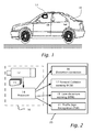
- Figures 1 and 2 illustrate a system 16 including a camera or image sensor 12 with a rolling shutter mountable in a vehicle 18, according to an embodiment of the present invention.
- Image sensor 12 imaging a field of view in the forward direction typically captures in real time a time series of image frames 15.
- An image processor 14 may be used to process image frames 15 simultaneously and/or in parallel to serve a number of driver assistance and/or control systems.
- Image sensor 12 may be monochrome or black-white, i.e. without color separation.
- image frames 15 may be used to serve a monitor/control system 23 which may include collision warning 17, lane departure warning 19, traffic sign recognition (TSR) 21 and structure from motion (SfM) with rolling shutter distortion correction 30 according to embodiments of the present invention.
- Structure from motion may include for example presenting three dimensional imagery on a display to the driver, measuring distance to objects being imaged or the detection of three dimensional structures including curbs, guard rails, structural barriers, e.g. concrete lane divider.
- Embodiments of the present invention may include exchange of information between SfM 30 and other driver assistance functions and/or systems including but not limited by FCW 17 and LDW 19.
- a Lane Departure Warning (LDW) 19 as part of warning system 23, may respond more strongly to a lane departure towards a guard rail or a barrier rather than a lane marker or even a white line.
- a Forward Collision Warning (FCW) system 19 may trigger sooner if the path to either side of in-path vehicle is blocked by a guard rail or another vehicle.
- image sensor refers to an object in real space being viewed by a camera.
- object refers to an object in real space being viewed by a camera.
- a guard rail along the edge of a road and a lane marker in the road are examples of objects.
- image refers to the image of one or more objects in image space at the focal plane of camera 12.
- Image coordinates (x,y) in small letters refer to image space and may be in arbitrary units or numbers of picture elements in the horizontal and vertical directions with the pixel dimensions assumed.
- image point refers to a point (x,y) in image space.
- pixel short for "picture element” and “image point” are used herein interchangeably.
- corresponding as used herein in the context of " corresponding” image points refers to image points of different image frames of a time sequence which have been found to be image points of the same object point.
- corresponding image points and “matching” image points are used herein interchangeably.
- time stamp refers to a point in time relative to a reference time which may be selected during a time sequence of image frames.
- time stamp as used herein is a capture time of an image point or image row of the rolling shutter. The time stamp may be further adjusted to correct for another known distortion in the camera other than that caused by the rolling shutter in which case the time stamp used is not strictly the capture time of the image point.
- image motion refers to motion of an image of an object in image space. From image frame 15 to a subsequent image frame 15 the points of the image of the object may map from one set of coordinates (x1,y1) to a different set of coordinates (x2,y2).
- image motion refers to the mapping of coordinates of an image from image frame to image frame or a function of the mapping.
- projection or “projecting” as used herein refers to camera or perspective projection unless otherwise indicated by the context.
- Figure 3 illustrates a simplified method 30, according to embodiments of the present invention for image distortion correction using a rolling shutter. Image frames are captured (step 703 ) with a camera equipped with a rolling shutter.
- Time stamps 70 are recorded (step 707 ) for multiple rows in the previous and base image frames or for multiple pixels per row in both.
- ego-motion is computed on a row by row or pixel by pixel basis responsive to time stamps 70, and more particularly the ego-motion may be responsive to the difference in time stamps 70 of corresponding pixels in the previous and base image frames.
- Ego-motion results 71 of the rows and/or of the pixels for corresponding rows and pixels. Ego-motion results may be represented by corrections to a global ego-motion matrix which would be valid for all pixels with the use of a global shutter instead of a rolling shutter.
- the corrected ego-motion results may be used pixel by pixel or row by row for further image processing such as computation in step 711 of image disparities for providing or displaying structure from motion (SfM).
- SfM image disparities for providing or displaying structure from motion
- an SfM algorithm using a global ego-motion computation assumes that all the pixels in image frame 15 are sampled simultaneously. However, when camera 12 has a rolling shutter, the assumption of simultaneous sampling for all pixels in a single image frame 15 is no longer valid. The rolling shutter therefore produces an image distortion, which affects performance of structure from motion (SfM) algorithm.
- a correction to the image distortion may be applied in two stages to the original structure from motion (SfM) algorithm: A. distance estimation correction and B. ego-motion correction.
- the distance correction for the rolling shutter effect of camera 12 is presented here in four main steps.
- the inputs include the structure from motion (SfM) distance estimation, the ego motion matrix C, time stamps approximation and time difference between the base and previous images.
- SfM motion
- C ego motion matrix
- time stamps approximation and time difference between the base and previous images Each of the following steps may be performed for every pixel of the base and previous images; or multiple pixels or multiple rows of the base and previous images:
- the input C is the ego motion matrix that describes the real-space motion of camera 12 while capturing the previous and base image frames 15 when the rolling shutter effect is not taken into account.
- ego motion matrix C describes the hypothetical situation in which camera 12 does not have a rolling shutter and all the pixels are simultaneously sampled.
- the term “simultaneous” abbreviated as “sim” is used to describe the situation when all the pixels are sampled simultaneously. So the ego motion matrix C describes ego-motion from previous-sim image to base-sim image.
- the term “rolling shutter”, abbreviated “RS” is used to describe the situation when all the pixels are not sampled exactly at the same moment or not sampled simultaneously, i.e camera 12 has a rolling shutter.
- the ego motion from previous-RS image frame 15 to base-RS image frame 15 is used.
- the desired ego motion matrix be denoted C d .
- a polynomial approximation may be used of ego-motion variation due to the rolling shutter.
- the power of the ego motion matrix C is calculated approximately, using a first order Taylor expansion.
- the distance is recalculated in the following way:
- the exact distance Z new to each object point imaged by an image point in the base image may be obtained, in real time, which is the real distance at the exact moment in which the image point was recorded.
- the real distance to each object point imaged by an image point in the exact moment in which the image point was recorded is not the distance sought. Instead it is desired to cancel the effect of the rolling shutting while camera 12 is moving d. What is needed is the distance obtained if camera 12 had no rolling shutter.
- the time stamp of the base pixel is used, to get the following ego motion matrix under assumption of the rolling shutter: C - t b dt
- the corrected ego motion matrices under assumption of the rolling shutter may be used in equations of section A1 to determine the previous image coordinates.
- the previous image coordinates may be used to determine the distances and disparities under assumption of a rolling shutter from the equations in section A3 above.
- the original structure from motion (SfM) algorithm includes a stage in which the ego motion matrix C is calculated.
- the matrix which describes the camera 12 movement from previous-RS to base-RS would be C ⁇
- the rolling shutter effect correction is applied to this stage by replacing the ego motion matrix C with C ⁇ pixel by pixel or row by row and adjusting all the equations previously presented accordingly.
- the structure from motion (SfM) algorithm uses an iterative process where the optimization goal is to minimize the distances between the epipolar lines corresponding to the previous points and the matching base points.
- Each iteration includes the following steps:
- v be a point in the base image, and let u be the corresponding point in the previous image (these points are the result of an earlier point matching stage).
- v and ⁇ be these points in the coordinate systems of the rotated cameras (step B1).
- D 0 is an equation with five unknowns ( r, y, p, a, b); so there are as many such equations as the number of point pairs. Neglecting second-order terms, new R and t are obtained by solving a system of linear equations.
Landscapes
- Engineering & Computer Science (AREA)
- Multimedia (AREA)
- Signal Processing (AREA)
- Image Processing (AREA)
- Image Analysis (AREA)
- Studio Devices (AREA)
- Closed-Circuit Television Systems (AREA)
Abstract
Description
- The present disclosure relates to correction for distortions arising from use of a rolling shutter, and more particularly for use in a camera based driver assistance/control system.
- Rolling shutter is a method of image acquisition in which each frame is recorded not from a snapshot of a single point in time, but rather by scanning across the image frame, for instance row by row. With a rolling shutter, not all parts of the image are recorded at exactly the same time, even though the whole frame may be displayed at the same time during playback. The rolling shutter is in contrast with a global shutter where the entire frame is exposed for the same time window.
- Ego-motion "self-motion" refers to the translation and orientation (e.g. yaw, pitch and roll) in time of moving camera. A measure of ego-motion or of the camera mounted in a vehicle is important for driver assistance and/or vehicle control systems in order to accurately detect, recognize and avoid false positive detections of: other vehicles, obstacles, lights, street signs, lane markers and/or guard rails in the road environment.
- Structure-from-Motion (SfM) refers to methods for recovering three-dimensional information of a scene that has been projected onto the focal plane(s) of a moving camera or multiple cameras. The structural information derived from a SfM algorithm may take the form of a set of projection matrices, one projection matrix per image frame, representing the relationship between a specific two-dimensional point in the image plane and its corresponding three-dimensional point. SfM algorithms rely on tracking specific image features from image frame to image frame to determine structural information concerning the scene.
- Aspects of the present invention seek to provide an improved method for correcting image distortion and system.
- According to an aspect of the invention, there is provided a method as in claim 1.
- According to an aspect of the invention, there is provided a system as in claim 8.
- Various systems and methods are disclosed herein for correcting image distortion during camera motion using a system including a processor and a camera having a rolling shutter. Multiple image frames are captured by the camera equipped with the rolling shutter. The captured image frames include a base image frame and a previous image frame. Multiple time stamps are recorded respectively for multiple corresponding image points in the previous and base image frames. For the corresponding image points, multiple ego-motions are computed responsive to the time stamps or capture times of the corresponding image points of the base image frame and the previous image frame to correct the image distortion caused by the rolling shutter. The computation of the ego-motions may be performed using image data from the image frames of the camera. The corresponding image points of the base image frame and the previous image frame are image points of the same object point. The computation of the ego-motions may be responsive to the time stamp difference between the corresponding image points. Image disparities may be computed based on the ego-motions. Distance to an object being imaged may be computed based on the ego-motions. The ego-motions may be determined by using an iterative process wherein an optimization goal is to minimize the distances between the epipolar lines corresponding to the image points in the previous image and the matching image points in the base image.
- The invention is herein described, by way of example only, with reference to the accompanying drawings, wherein:
-
Figures 1 and 2 illustrate a system including a camera with a rolling shutter mountable in a vehicle, according to an embodiment of the present invention. -
Figure 3 illustrates a simplified method , according to embodiments of the present invention. - The foregoing and/or other aspects will become apparent from the following detailed description when considered in conjunction with the accompanying drawing figures.
- Reference will now be made in detail to embodiments of the present invention, examples of which are illustrated in the accompanying drawings, wherein like reference numerals refer to the like elements throughout. The embodiments are described below to explain the present invention by referring to the figures.
- Before explaining embodiments of the invention in detail, it is to be understood that the invention is not limited in its application to the details of design and the arrangement of the components set forth in the following description or illustrated in the drawings. The invention is capable of other embodiments or of being practiced or carried out in various ways. Also, it is to be understood that the phraseology and terminology employed herein is for the purpose of description and should not be regarded as limiting.
- By way of introduction, embodiments of the present invention are based on ego-motion computations from the image data of a moving camera. When ego-motion computations are available as in driver assistance systems and/or vehicle control systems, computational resources may be saved by using the available ego-motion information. By way of example, a structure from motion (SfM) algorithm may use an ego motion matrix C which describes the ego-motion of a camera moving in real space while capturing a pair of image frames ("base" and "previous"). The SfM algorithm may use the ego motion matrix C and image point correspondences between the pair of image frames to calculate real space distances to objects being imaged. Such an ego motion matrix C describes the camera motion while capturing two image frames in which all pixels of each image frame are sampled at the same time. A rolling shutter renders the use of a single ego motion matrix C inadequate, as the motion of the camera is different for each pair of corresponding image points. Therefore, in order to fully describe the motion of the camera between two image frames, as many ego motion matrix matrices C are required as the number of corresponding pixel pairs. Such an approach would be computationally prohibitive for use in driver assistance and control systems which are required to respond in real time.
- However, assuming that the ego motion matrix C between points sampled at time t=0 is known, and that the characteristics of the camera motion did not change considerably between the two image frames, the timestamps between rows may be used to compute the real ego motion between capture times of image points. In practice, because of various other distortions the captured image undergoes (e.g. distortion from optical system and/or camera calibration distortion), a different time stamp for each pixel may be obtained and used rather than a time stamp per row. In this way, the other distortions may be considered in addition to the rolling shutter distortion by adjusting the time stamp according to the known distortion per pixel.
- Referring now to the drawings, reference is now made to
Figures 1 and 2 which illustrate asystem 16 including a camera orimage sensor 12 with a rolling shutter mountable in avehicle 18, according to an embodiment of the present invention.Image sensor 12, imaging a field of view in the forward direction typically captures in real time a time series ofimage frames 15. Animage processor 14 may be used to processimage frames 15 simultaneously and/or in parallel to serve a number of driver assistance and/or control systems.Image sensor 12 may be monochrome or black-white, i.e. without color separation. By way of example inFigure 2 ,image frames 15 may be used to serve a monitor/control system 23 which may includecollision warning 17,lane departure warning 19, traffic sign recognition (TSR) 21 and structure from motion (SfM) with rollingshutter distortion correction 30 according to embodiments of the present invention. Structure from motion may include for example presenting three dimensional imagery on a display to the driver, measuring distance to objects being imaged or the detection of three dimensional structures including curbs, guard rails, structural barriers, e.g. concrete lane divider. Embodiments of the present invention may include exchange of information between SfM 30 and other driver assistance functions and/or systems including but not limited by FCW 17 and LDW 19. For example, a Lane Departure Warning (LDW) 19 as part ofwarning system 23, may respond more strongly to a lane departure towards a guard rail or a barrier rather than a lane marker or even a white line. A Forward Collision Warning (FCW)system 19 may trigger sooner if the path to either side of in-path vehicle is blocked by a guard rail or another vehicle. - The terms "camera" and "image sensor" are used herein interchangeably. The term "object" as used herein refers to an object in real space being viewed by a camera. A guard rail along the edge of a road and a lane marker in the road are examples of objects. The term "image" refers to the image of one or more objects in image space at the focal plane of
camera 12. Image coordinates (x,y) in small letters refer to image space and may be in arbitrary units or numbers of picture elements in the horizontal and vertical directions with the pixel dimensions assumed. - The term "image point" as used herein refers to a point (x,y) in image space. The term "pixel" short for "picture element" and "image point" are used herein interchangeably. The term "corresponding" as used herein in the context of " corresponding" image points refers to image points of different image frames of a time sequence which have been found to be image points of the same object point. The terms "corresponding" image points and "matching" image points are used herein interchangeably.
- The term "time stamp" as used herein refers to a point in time relative to a reference time which may be selected during a time sequence of image frames. The term "time stamp" as used herein is a capture time of an image point or image row of the rolling shutter. The time stamp may be further adjusted to correct for another known distortion in the camera other than that caused by the rolling shutter in which case the time stamp used is not strictly the capture time of the image point.
- The term "image motion" refers to motion of an image of an object in image space. From
image frame 15 to asubsequent image frame 15 the points of the image of the object may map from one set of coordinates (x1,y1) to a different set of coordinates (x2,y2). The term "image motion" refers to the mapping of coordinates of an image from image frame to image frame or a function of the mapping. The term "projection" or "projecting" as used herein refers to camera or perspective projection unless otherwise indicated by the context. Reference is now also made toFigure 3 which illustrates asimplified method 30, according to embodiments of the present invention for image distortion correction using a rolling shutter. Image frames are captured (step 703) with a camera equipped with a rolling shutter.Time stamps 70 are recorded (step 707) for multiple rows in the previous and base image frames or for multiple pixels per row in both. Instep 709, ego-motion is computed on a row by row or pixel by pixel basis responsive totime stamps 70, and more particularly the ego-motion may be responsive to the difference intime stamps 70 of corresponding pixels in the previous and base image frames. Ego-motion results 71 of the rows and/or of the pixels for corresponding rows and pixels. Ego-motion results may be represented by corrections to a global ego-motion matrix which would be valid for all pixels with the use of a global shutter instead of a rolling shutter. The corrected ego-motion results may be used pixel by pixel or row by row for further image processing such as computation instep 711 of image disparities for providing or displaying structure from motion (SfM). In the description that follows,method 30 is described in further detail with SfM as an example. - As previously stated, an SfM algorithm using a global ego-motion computation assumes that all the pixels in
image frame 15 are sampled simultaneously. However, whencamera 12 has a rolling shutter, the assumption of simultaneous sampling for all pixels in asingle image frame 15 is no longer valid.. The rolling shutter therefore produces an image distortion, which affects performance of structure from motion (SfM) algorithm. - A correction to the image distortion may be applied in two stages to the original structure from motion (SfM) algorithm: A. distance estimation correction and B. ego-motion correction.
- The distance correction for the rolling shutter effect of
camera 12 is presented here in four main steps. The inputs include the structure from motion (SfM) distance estimation, the ego motion matrix C, time stamps approximation and time difference between the base and previous images. Each of the following steps may be performed for every pixel of the base and previous images; or multiple pixels or multiple rows of the base and previous images: - The following equations relate the image coordinates of the base image to the image coordinates of the previous image when the global ego-motion of
camera 12 is known.


where b refers to base image and p refers to the previous image, x,y are image coordinates, f is the focal length ofcamera 12 and X,Y,Z are real-space Cartesian coordinates of the object point being imaged relative to the camera coordinates. X is the horizontal coordinate, Y is the vertical coordinate and Z is the distance to the object in the forward direction. C is an ego-motion matrix under the assumption of a global shutter.
C-1 is the inverse of ego-motion matrix C. - The input C is the ego motion matrix that describes the real-space motion of
camera 12 while capturing the previous and base image frames 15 when the rolling shutter effect is not taken into account. In other words, ego motion matrix C describes the hypothetical situation in whichcamera 12 does not have a rolling shutter and all the pixels are simultaneously sampled. The term "simultaneous" abbreviated as "sim" is used to describe the situation when all the pixels are sampled simultaneously. So the ego motion matrix C describes ego-motion from previous-sim image to base-sim image. The term "rolling shutter", abbreviated "RS" is used to describe the situation when all the pixels are not sampled exactly at the same moment or not sampled simultaneously,i.e camera 12 has a rolling shutter. - In order to correct the effect of the rolling shutter, the ego motion from previous-
RS image frame 15 to base-RS image frame 15 is used. Let the desired ego motion matrix be denoted Cd. Given that the time difference between the previous and base images is dt, we obtain the following expression for the desired ego-motion matrix Cd :
where tb and tp are the base point and previous point's time stamps respectively. - To obtain a representation of the time stamp of a pixel, a polynomial approximation may be used of ego-motion variation due to the rolling shutter. The power of the ego motion matrix C is calculated approximately, using a first order Taylor expansion. The first order Taylor expansion is linear where approximation of Cε , for ε is small, yields the following result:


where R is a rotation matrix and I is an identity matrix. - The distance is recalculated in the following way:
- 1. The previous coordinates xp,yp of the previous image frame are rotated to match the base coordinate xb,yb of the base image frame so that
camera 12 recording the previous image andcamera 12 recording the base image are parallel and have the same focus of expansion (FOE)). - 2. The focus of expansion FOE is calculated by the following equation:

where tx,ty,tz are the translation vector components. - 3. The disparity, d, is calculated: d = rb - rp, where rb is the distance from the pixel to the FOE in the base image and rp is the same for the previous image.
- 4. Finally, the distance is calculated:

- By now the exact distance Znew to each object point imaged by an image point in the base image may be obtained, in real time, which is the real distance at the exact moment in which the image point was recorded. The real distance to each object point imaged by an image point in the exact moment in which the image point was recorded is not the distance sought. Instead it is desired to cancel the effect of the rolling shutting while
camera 12 is moving d. What is needed is the distance obtained ifcamera 12 had no rolling shutter. To get the distance ifcamera 12 had no rolling shutter, the time stamp of the base pixel is used, to get the following ego motion matrix under assumption of the rolling shutter:
- Multiplying the ego motion matrix in the new base world point found, gets the final world point and the desired distance from it. The corrected ego motion matrices under assumption of the rolling shutter may be used in equations of section A1 to determine the previous image coordinates. The previous image coordinates may be used to determine the distances and disparities under assumption of a rolling shutter from the equations in section A3 above.
- As stated previously, the original structure from motion (SfM) algorithm includes a stage in which the ego motion matrix C is calculated. As explained in the previous section, in the presence of rolling shutter distortions, the matrix which describes the
camera 12 movement from previous-RS to base-RS would be Cα , where the ego motion matrix C is the camera matrix from previous-sim image to base-sim image is: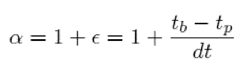
and therefore ε is small. In essence, the rolling shutter effect correction is applied to this stage by replacing the ego motion matrix C with Cα pixel by pixel or row by row and adjusting all the equations previously presented accordingly. - In order to find the ego motion matrix, the structure from motion (SfM) algorithm uses an iterative process where the optimization goal is to minimize the distances between the epipolar lines corresponding to the previous points and the matching base points. Each iteration includes the following steps:
- 1. Both cameras 12 (previous and
base camera 12 orientations) are rotated so that the line connecting their centers would be perpendicular to both image planes. This rotation is done assuming that the matrix Rp and translation vector tp obtained in the previous iteration (or given as the initial guess) describe the motion from previous to base. - 2. In this position the new rotation matrix would be approximately I and the translation vector would be close to:

- Thus, after the rotation is done in the first step, the rotation matrix and translation vector between the cameras may be written as:

and
where r, y, p, a, b are unknown parameters assumed to be small. 3. Let v be a point in the base image, and let u be the corresponding point in the previous image (these points are the result of an earlier point matching stage). Let v and ũ be these points in the coordinate systems of the rotated cameras (step B1). The distance between v and the epipolar line determined by ũ is: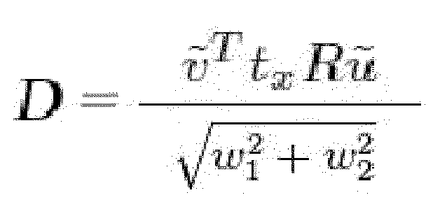
where
- D = 0 is an equation with five unknowns (r, y, p, a, b); so there are as many such equations as the number of point pairs. Neglecting second-order terms, new R and t are obtained by solving a system of linear equations.
- Having no rolling shutter effects, the ego motion matrix from base image to previous image is:

where the first and last matrices describe the rotation of the cameras back to their original position,
and translation vector t and rotation matrix R describe the motion between the parallel cameras-after step B1). - Considering the rolling shutter effect, the corrected ego motion matrix would be

and thus:
- Expanding this expression and using first order Taylor expansions gives the corrected expressions for the translation and rotation matrices, and a new equation (D=0) with the same five unknowns is obtained, only here it incorporates the time stamp difference between pixels caused by the rolling shutter.
- The indefinite articles "a" and "an" is used herein, such as "a camera", "an image frame " have the meaning of "one or more" that is "one or more cameras" or "one or more image frames".
- Although selected embodiments of the present invention have been shown and described, it is to be understood the present invention is not limited to the described embodiments. Instead, it is to be appreciated that changes may be made to these embodiments, the scope of which is defined by the claims..
- All optional and preferred features and modifications of the described embodiments and dependent claims are usable in all aspects of the invention taught herein. Furthermore, the individual features of the dependent claims, as well as all optional and preferred features and modifications of the described embodiments are combinable and interchangeable with one another.
- The disclosures in United States patent application number
61/767,332
Claims (14)
- A method for correcting image distortion during camera motion using a system including a processor and a camera having a rolling shutter, the method including:capturing a plurality of image frames by the camera equipped with the rolling shutter, wherein the captured image frames include a base image frame and a previous image frame;recording a plurality of time stamps respectively for a plurality of corresponding image points in the previous and base image frames; andfor the corresponding image points, computing a plurality of ego-motions responsive to the time stamps of the corresponding image points of the base image frame and the previous image frame thereby correcting the image distortion caused by the rolling shutter.
- The method of claim 1, wherein said computing said ego-motions is performed using image data from the image frames of the camera.
- The method according to any of claims 1-2, wherein the corresponding image points of the base image frame and the previous image frame are image points of the same object point.
- The method of according to any of claims 1-3, wherein said computing said ego-motions is responsive to the time stamp difference between the corresponding image points
- The method according to any of claims 1-4, further including:computing image disparities based on the ego-motions.
- The method according to any of claims 1-5, further including:computing distance to an object being imaged based on the ego-motions.
- The method of according to any of claims 1-6, further including:determining the ego-motions by using an iterative process wherein an optimization goal is to minimize the distances between the epipolar lines corresponding to the image points in the previous image and the matching image points in the base image.
- A system for correcting image distortion during camera motion, the system including a processor and a camera having a rolling shutter, the system operable to:capture a plurality of image frames by the camera equipped with the rolling shutter, wherein the captured image frames include a base image frame and a previous image frame;record a plurality of time stamps respectively for a plurality of corresponding image points in the previous and base image frames; andfor the corresponding image points, compute a plurality of ego-motions responsive to the time stamps of the corresponding image points of the base image frame and the previous image frame and correct thereby the image distortion caused by the rolling shutter.
- The system of claim 8, further operable to compute the ego-motions from image data from the image frames of the camera.
- The system according to any of claims 8-9, wherein the corresponding image points of the base image frame and the previous image frame are image points of the same object point.
- The system according to any of claims 8-10, wherein the computation of the ego-motions is responsive to the time stamp difference between the corresponding image points
- The system according to any of claims 8-11, further operable to
compute image disparities based on the ego-motions. - The system according to any of claims 8-12, further operable to
compute distance to an object being imaged based on the ego-motions. - The system according to any of claims 8-13, further operable to:determine the ego-motions by using an iterative process wherein an optimization goal is to minimize the image distances between the epipolar lines corresponding to the image points in the previous image and the matching image points in the base image.
Applications Claiming Priority (1)
| Application Number | Priority Date | Filing Date | Title |
|---|---|---|---|
| US201361767332P | 2013-02-21 | 2013-02-21 |
Publications (2)
| Publication Number | Publication Date |
|---|---|
| EP2770728A2 true EP2770728A2 (en) | 2014-08-27 |
| EP2770728A3 EP2770728A3 (en) | 2016-09-07 |
Family
ID=50193407
Family Applications (1)
| Application Number | Title | Priority Date | Filing Date |
|---|---|---|---|
| EP14275028.0A Withdrawn EP2770728A3 (en) | 2013-02-21 | 2014-02-21 | Image distortion correction of a camera with a rolling shutter |
Country Status (2)
| Country | Link |
|---|---|
| US (4) | US9277132B2 (en) |
| EP (1) | EP2770728A3 (en) |
Cited By (1)
| Publication number | Priority date | Publication date | Assignee | Title |
|---|---|---|---|---|
| US10079975B2 (en) | 2013-02-21 | 2018-09-18 | Mobileye Vision Technologies Ltd. | Image distortion correction of a camera with a rolling shutter |
Families Citing this family (80)
| Publication number | Priority date | Publication date | Assignee | Title |
|---|---|---|---|---|
| CN104364608B (en) * | 2013-04-15 | 2017-11-24 | 松下知识产权经营株式会社 | Distnace determination device and method for measuring distance |
| CN104954631B (en) * | 2014-03-25 | 2018-02-27 | 腾讯科技(深圳)有限公司 | A kind of method for processing video frequency, device and system |
| US9727967B2 (en) * | 2014-06-23 | 2017-08-08 | Samsung Electronics Co., Ltd. | Methods for determining estimated depth in an image and systems thereof |
| JP6385212B2 (en) * | 2014-09-09 | 2018-09-05 | キヤノン株式会社 | Image processing apparatus and method, imaging apparatus, and image generation apparatus |
| US20170374256A1 (en) * | 2016-06-24 | 2017-12-28 | Qualcomm Incorporated | Method and apparatus for rolling shutter compensation |
| DE102016124089B4 (en) | 2016-12-12 | 2024-09-19 | Valeo Schalter Und Sensoren Gmbh | Method for detecting an object in the environment of a motor vehicle using an image received by a camera with determination of a detection time, image processing device, camera system and motor vehicle |
| US10255507B2 (en) * | 2016-12-19 | 2019-04-09 | Canon Kabushiki Kaisha | Detection of an object in a distorted image |
| US10067509B1 (en) | 2017-03-10 | 2018-09-04 | TuSimple | System and method for occluding contour detection |
| US10671873B2 (en) | 2017-03-10 | 2020-06-02 | Tusimple, Inc. | System and method for vehicle wheel detection |
| US11587304B2 (en) | 2017-03-10 | 2023-02-21 | Tusimple, Inc. | System and method for occluding contour detection |
| US10147193B2 (en) | 2017-03-10 | 2018-12-04 | TuSimple | System and method for semantic segmentation using hybrid dilated convolution (HDC) |
| US9953236B1 (en) | 2017-03-10 | 2018-04-24 | TuSimple | System and method for semantic segmentation using dense upsampling convolution (DUC) |
| US10311312B2 (en) | 2017-08-31 | 2019-06-04 | TuSimple | System and method for vehicle occlusion detection |
| US10710592B2 (en) | 2017-04-07 | 2020-07-14 | Tusimple, Inc. | System and method for path planning of autonomous vehicles based on gradient |
| US10471963B2 (en) | 2017-04-07 | 2019-11-12 | TuSimple | System and method for transitioning between an autonomous and manual driving mode based on detection of a drivers capacity to control a vehicle |
| US9952594B1 (en) | 2017-04-07 | 2018-04-24 | TuSimple | System and method for traffic data collection using unmanned aerial vehicles (UAVs) |
| US10552691B2 (en) | 2017-04-25 | 2020-02-04 | TuSimple | System and method for vehicle position and velocity estimation based on camera and lidar data |
| US10558864B2 (en) | 2017-05-18 | 2020-02-11 | TuSimple | System and method for image localization based on semantic segmentation |
| US10481044B2 (en) | 2017-05-18 | 2019-11-19 | TuSimple | Perception simulation for improved autonomous vehicle control |
| US10474790B2 (en) | 2017-06-02 | 2019-11-12 | TuSimple | Large scale distributed simulation for realistic multiple-agent interactive environments |
| US10762635B2 (en) | 2017-06-14 | 2020-09-01 | Tusimple, Inc. | System and method for actively selecting and labeling images for semantic segmentation |
| US10303522B2 (en) | 2017-07-01 | 2019-05-28 | TuSimple | System and method for distributed graphics processing unit (GPU) computation |
| US10493988B2 (en) | 2017-07-01 | 2019-12-03 | TuSimple | System and method for adaptive cruise control for defensive driving |
| US10752246B2 (en) | 2017-07-01 | 2020-08-25 | Tusimple, Inc. | System and method for adaptive cruise control with proximate vehicle detection |
| US10737695B2 (en) | 2017-07-01 | 2020-08-11 | Tusimple, Inc. | System and method for adaptive cruise control for low speed following |
| US10308242B2 (en) | 2017-07-01 | 2019-06-04 | TuSimple | System and method for using human driving patterns to detect and correct abnormal driving behaviors of autonomous vehicles |
| US11029693B2 (en) | 2017-08-08 | 2021-06-08 | Tusimple, Inc. | Neural network based vehicle dynamics model |
| US10360257B2 (en) | 2017-08-08 | 2019-07-23 | TuSimple | System and method for image annotation |
| US10816354B2 (en) | 2017-08-22 | 2020-10-27 | Tusimple, Inc. | Verification module system and method for motion-based lane detection with multiple sensors |
| US10762673B2 (en) | 2017-08-23 | 2020-09-01 | Tusimple, Inc. | 3D submap reconstruction system and method for centimeter precision localization using camera-based submap and LiDAR-based global map |
| US10303956B2 (en) | 2017-08-23 | 2019-05-28 | TuSimple | System and method for using triplet loss for proposal free instance-wise semantic segmentation for lane detection |
| US10565457B2 (en) | 2017-08-23 | 2020-02-18 | Tusimple, Inc. | Feature matching and correspondence refinement and 3D submap position refinement system and method for centimeter precision localization using camera-based submap and LiDAR-based global map |
| US10678234B2 (en) | 2017-08-24 | 2020-06-09 | Tusimple, Inc. | System and method for autonomous vehicle control to minimize energy cost |
| US10783381B2 (en) | 2017-08-31 | 2020-09-22 | Tusimple, Inc. | System and method for vehicle occlusion detection |
| US10649458B2 (en) | 2017-09-07 | 2020-05-12 | Tusimple, Inc. | Data-driven prediction-based system and method for trajectory planning of autonomous vehicles |
| US10953880B2 (en) | 2017-09-07 | 2021-03-23 | Tusimple, Inc. | System and method for automated lane change control for autonomous vehicles |
| US10782694B2 (en) | 2017-09-07 | 2020-09-22 | Tusimple, Inc. | Prediction-based system and method for trajectory planning of autonomous vehicles |
| US10782693B2 (en) | 2017-09-07 | 2020-09-22 | Tusimple, Inc. | Prediction-based system and method for trajectory planning of autonomous vehicles |
| US10953881B2 (en) | 2017-09-07 | 2021-03-23 | Tusimple, Inc. | System and method for automated lane change control for autonomous vehicles |
| US10656644B2 (en) | 2017-09-07 | 2020-05-19 | Tusimple, Inc. | System and method for using human driving patterns to manage speed control for autonomous vehicles |
| US10552979B2 (en) | 2017-09-13 | 2020-02-04 | TuSimple | Output of a neural network method for deep odometry assisted by static scene optical flow |
| US10671083B2 (en) | 2017-09-13 | 2020-06-02 | Tusimple, Inc. | Neural network architecture system for deep odometry assisted by static scene optical flow |
| US10733465B2 (en) | 2017-09-20 | 2020-08-04 | Tusimple, Inc. | System and method for vehicle taillight state recognition |
| US10387736B2 (en) | 2017-09-20 | 2019-08-20 | TuSimple | System and method for detecting taillight signals of a vehicle |
| US10962979B2 (en) | 2017-09-30 | 2021-03-30 | Tusimple, Inc. | System and method for multitask processing for autonomous vehicle computation and control |
| US10768626B2 (en) | 2017-09-30 | 2020-09-08 | Tusimple, Inc. | System and method for providing multiple agents for decision making, trajectory planning, and control for autonomous vehicles |
| US10970564B2 (en) | 2017-09-30 | 2021-04-06 | Tusimple, Inc. | System and method for instance-level lane detection for autonomous vehicle control |
| US10410055B2 (en) | 2017-10-05 | 2019-09-10 | TuSimple | System and method for aerial video traffic analysis |
| US10666730B2 (en) | 2017-10-28 | 2020-05-26 | Tusimple, Inc. | Storage architecture for heterogeneous multimedia data |
| US10812589B2 (en) | 2017-10-28 | 2020-10-20 | Tusimple, Inc. | Storage architecture for heterogeneous multimedia data |
| US10739775B2 (en) * | 2017-10-28 | 2020-08-11 | Tusimple, Inc. | System and method for real world autonomous vehicle trajectory simulation |
| US10657390B2 (en) | 2017-11-27 | 2020-05-19 | Tusimple, Inc. | System and method for large-scale lane marking detection using multimodal sensor data |
| US10528851B2 (en) | 2017-11-27 | 2020-01-07 | TuSimple | System and method for drivable road surface representation generation using multimodal sensor data |
| US10528823B2 (en) | 2017-11-27 | 2020-01-07 | TuSimple | System and method for large-scale lane marking detection using multimodal sensor data |
| US10877476B2 (en) | 2017-11-30 | 2020-12-29 | Tusimple, Inc. | Autonomous vehicle simulation system for analyzing motion planners |
| US10860018B2 (en) | 2017-11-30 | 2020-12-08 | Tusimple, Inc. | System and method for generating simulated vehicles with configured behaviors for analyzing autonomous vehicle motion planners |
| EP4283430A3 (en) | 2018-01-09 | 2024-01-24 | Tusimple, Inc. | Real-time remote control of vehicles with high redundancy |
| CN111989716B (en) | 2018-01-11 | 2022-11-15 | 图森有限公司 | Monitoring system for autonomous vehicle operation |
| US12270661B2 (en) | 2018-02-14 | 2025-04-08 | Tusimple, Inc. | Lane marking localization and fusion |
| US11009365B2 (en) | 2018-02-14 | 2021-05-18 | Tusimple, Inc. | Lane marking localization |
| US11009356B2 (en) | 2018-02-14 | 2021-05-18 | Tusimple, Inc. | Lane marking localization and fusion |
| US10685244B2 (en) | 2018-02-27 | 2020-06-16 | Tusimple, Inc. | System and method for online real-time multi-object tracking |
| US10685239B2 (en) | 2018-03-18 | 2020-06-16 | Tusimple, Inc. | System and method for lateral vehicle detection |
| CN110378184A (en) | 2018-04-12 | 2019-10-25 | 北京图森未来科技有限公司 | A kind of image processing method applied to automatic driving vehicle, device |
| CN110458854B (en) | 2018-05-02 | 2022-11-15 | 北京图森未来科技有限公司 | Road edge detection method and device |
| US11104334B2 (en) | 2018-05-31 | 2021-08-31 | Tusimple, Inc. | System and method for proximate vehicle intention prediction for autonomous vehicles |
| US10839234B2 (en) | 2018-09-12 | 2020-11-17 | Tusimple, Inc. | System and method for three-dimensional (3D) object detection |
| CN118289018A (en) | 2018-09-13 | 2024-07-05 | 图森有限公司 | Remote safe driving method and system |
| US10796402B2 (en) | 2018-10-19 | 2020-10-06 | Tusimple, Inc. | System and method for fisheye image processing |
| US11132586B2 (en) * | 2018-10-29 | 2021-09-28 | Nec Corporation | Rolling shutter rectification in images/videos using convolutional neural networks with applications to SFM/SLAM with rolling shutter images/videos |
| US10942271B2 (en) | 2018-10-30 | 2021-03-09 | Tusimple, Inc. | Determining an angle between a tow vehicle and a trailer |
| CN111366938B (en) | 2018-12-10 | 2023-03-14 | 北京图森智途科技有限公司 | Method, device and vehicle for measuring trailer angle |
| CN111319629B (en) | 2018-12-14 | 2021-07-16 | 北京图森智途科技有限公司 | A method, device and system for forming an autonomous vehicle fleet |
| US10893201B2 (en) * | 2019-05-16 | 2021-01-12 | Pelco, Inc. | Video stabilization method with non-linear frame motion correction in three axes |
| CN110198415B (en) * | 2019-05-26 | 2021-08-24 | 初速度(苏州)科技有限公司 | Method and device for determining image timestamp |
| CN112889271B (en) * | 2019-05-29 | 2022-06-07 | 华为技术有限公司 | Image processing method and device |
| US11823460B2 (en) | 2019-06-14 | 2023-11-21 | Tusimple, Inc. | Image fusion for autonomous vehicle operation |
| WO2021091608A2 (en) | 2019-10-08 | 2021-05-14 | Massachusetts Institute Of Technology | Wide-area motion imaging systems and methods |
| EP3893150A1 (en) | 2020-04-09 | 2021-10-13 | Tusimple, Inc. | Camera pose estimation techniques |
| AU2021203567A1 (en) | 2020-06-18 | 2022-01-20 | Tusimple, Inc. | Angle and orientation measurements for vehicles with multiple drivable sections |
Family Cites Families (15)
| Publication number | Priority date | Publication date | Assignee | Title |
|---|---|---|---|---|
| US6307959B1 (en) * | 1999-07-14 | 2001-10-23 | Sarnoff Corporation | Method and apparatus for estimating scene structure and ego-motion from multiple images of a scene using correlation |
| US20050140670A1 (en) * | 2003-11-20 | 2005-06-30 | Hong Wu | Photogrammetric reconstruction of free-form objects with curvilinear structures |
| JP3922245B2 (en) * | 2003-11-20 | 2007-05-30 | 日産自動車株式会社 | Vehicle periphery monitoring apparatus and method |
| JP4509917B2 (en) * | 2005-11-21 | 2010-07-21 | 株式会社メガチップス | Image processing apparatus and camera system |
| US8488895B2 (en) | 2006-05-31 | 2013-07-16 | Indiana University Research And Technology Corp. | Laser scanning digital camera with pupil periphery illumination and potential for multiply scattered light imaging |
| US8169519B1 (en) * | 2007-12-26 | 2012-05-01 | Google Inc. | System and method for reducing motion blur using CCD charge shifting |
| US8456517B2 (en) | 2008-07-09 | 2013-06-04 | Primesense Ltd. | Integrated processor for 3D mapping |
| TWI425445B (en) * | 2009-09-29 | 2014-02-01 | Nat Univ Tsing Hua | Method and detecting system for determining quantity of self-motion of a moving platform |
| US8964041B2 (en) * | 2011-04-07 | 2015-02-24 | Fr Vision Ab | System and method for video stabilization of rolling shutter cameras |
| US8744169B2 (en) * | 2011-05-31 | 2014-06-03 | Toyota Motor Europe Nv/Sa | Voting strategy for visual ego-motion from stereo |
| WO2012175703A1 (en) | 2011-06-24 | 2012-12-27 | Trident Microsystems, Inc. | Method and system for reliable reflective object detection using display light scene illumination |
| US8786716B2 (en) * | 2011-08-15 | 2014-07-22 | Apple Inc. | Rolling shutter reduction based on motion sensors |
| US8913140B2 (en) * | 2011-08-15 | 2014-12-16 | Apple Inc. | Rolling shutter reduction based on motion sensors |
| US9460495B2 (en) | 2012-04-06 | 2016-10-04 | Microsoft Technology Licensing, Llc | Joint video stabilization and rolling shutter correction on a generic platform |
| US9277132B2 (en) * | 2013-02-21 | 2016-03-01 | Mobileye Vision Technologies Ltd. | Image distortion correction of a camera with a rolling shutter |
-
2014
- 2014-02-20 US US14/185,217 patent/US9277132B2/en active Active
- 2014-02-21 EP EP14275028.0A patent/EP2770728A3/en not_active Withdrawn
-
2016
- 2016-02-29 US US15/055,723 patent/US10079975B2/en active Active
-
2018
- 2018-09-17 US US16/132,730 patent/US20190089888A1/en not_active Abandoned
-
2019
- 2019-08-05 US US16/531,425 patent/US10834324B2/en active Active
Non-Patent Citations (1)
| Title |
|---|
| None |
Cited By (2)
| Publication number | Priority date | Publication date | Assignee | Title |
|---|---|---|---|---|
| US10079975B2 (en) | 2013-02-21 | 2018-09-18 | Mobileye Vision Technologies Ltd. | Image distortion correction of a camera with a rolling shutter |
| US10834324B2 (en) | 2013-02-21 | 2020-11-10 | Mobileye Vision Technologies Ltd. | Image distortion correction of a camera with a rolling shutter |
Also Published As
| Publication number | Publication date |
|---|---|
| US20160182793A1 (en) | 2016-06-23 |
| US9277132B2 (en) | 2016-03-01 |
| US10079975B2 (en) | 2018-09-18 |
| US20190356830A1 (en) | 2019-11-21 |
| US20140232887A1 (en) | 2014-08-21 |
| US20190089888A1 (en) | 2019-03-21 |
| US10834324B2 (en) | 2020-11-10 |
| EP2770728A3 (en) | 2016-09-07 |
Similar Documents
| Publication | Publication Date | Title |
|---|---|---|
| US10834324B2 (en) | Image distortion correction of a camera with a rolling shutter | |
| US11763571B2 (en) | Monocular cued detection of three-dimensional structures from depth images | |
| US10685424B2 (en) | Dense structure from motion | |
| JP6896044B2 (en) | Road vertical contour detection | |
| US10097812B2 (en) | Stereo auto-calibration from structure-from-motion | |
| US8102427B2 (en) | Camera egomotion estimation from an infra-red image sequence for night vision | |
| US8385595B2 (en) | Motion detection method, apparatus and system | |
| JP6779365B2 (en) | Object detection device and vehicle | |
| KR101544021B1 (en) | Apparatus and method for generating 3d map | |
| US10192141B2 (en) | Determining scale of three dimensional information | |
| KR20190134303A (en) | Apparatus and method for image recognition | |
| KR100574227B1 (en) | Apparatus and method for extracting object motion that compensates for camera movement | |
| EP4016444A1 (en) | Method for rectification of images and/or image points, camera-based system and vehicle | |
| JP4696925B2 (en) | Image processing device | |
| CN117274670A (en) | Point cloud annotation method and device, computer-readable storage medium, terminal |
Legal Events
| Date | Code | Title | Description |
|---|---|---|---|
| PUAI | Public reference made under article 153(3) epc to a published international application that has entered the european phase |
Free format text: ORIGINAL CODE: 0009012 |
|
| 17P | Request for examination filed |
Effective date: 20140221 |
|
| AK | Designated contracting states |
Kind code of ref document: A2 Designated state(s): AL AT BE BG CH CY CZ DE DK EE ES FI FR GB GR HR HU IE IS IT LI LT LU LV MC MK MT NL NO PL PT RO RS SE SI SK SM TR |
|
| AX | Request for extension of the european patent |
Extension state: BA ME |
|
| RAP1 | Party data changed (applicant data changed or rights of an application transferred) |
Owner name: MOBILEYE VISION TECHNOLOGIES LTD. |
|
| PUAL | Search report despatched |
Free format text: ORIGINAL CODE: 0009013 |
|
| AK | Designated contracting states |
Kind code of ref document: A3 Designated state(s): AL AT BE BG CH CY CZ DE DK EE ES FI FR GB GR HR HU IE IS IT LI LT LU LV MC MK MT NL NO PL PT RO RS SE SI SK SM TR |
|
| AX | Request for extension of the european patent |
Extension state: BA ME |
|
| RIC1 | Information provided on ipc code assigned before grant |
Ipc: H04N 5/232 20060101AFI20160802BHEP |
|
| STAA | Information on the status of an ep patent application or granted ep patent |
Free format text: STATUS: REQUEST FOR EXAMINATION WAS MADE |
|
| STAA | Information on the status of an ep patent application or granted ep patent |
Free format text: STATUS: THE APPLICATION IS DEEMED TO BE WITHDRAWN |
|
| 18D | Application deemed to be withdrawn |
Effective date: 20170308 |