EP2770479B1 - Electronic device and method of operating electronic device - Google Patents
Electronic device and method of operating electronic device Download PDFInfo
- Publication number
- EP2770479B1 EP2770479B1 EP14155011.1A EP14155011A EP2770479B1 EP 2770479 B1 EP2770479 B1 EP 2770479B1 EP 14155011 A EP14155011 A EP 14155011A EP 2770479 B1 EP2770479 B1 EP 2770479B1
- Authority
- EP
- European Patent Office
- Prior art keywords
- unit
- tracking
- image data
- movement
- amount
- Prior art date
- Legal status (The legal status is an assumption and is not a legal conclusion. Google has not performed a legal analysis and makes no representation as to the accuracy of the status listed.)
- Active
Links
Images



Classifications
-
- G—PHYSICS
- G06—COMPUTING OR CALCULATING; COUNTING
- G06T—IMAGE DATA PROCESSING OR GENERATION, IN GENERAL
- G06T7/00—Image analysis
- G06T7/20—Analysis of motion
-
- G—PHYSICS
- G06—COMPUTING OR CALCULATING; COUNTING
- G06T—IMAGE DATA PROCESSING OR GENERATION, IN GENERAL
- G06T7/00—Image analysis
- G06T7/20—Analysis of motion
- G06T7/246—Analysis of motion using feature-based methods, e.g. the tracking of corners or segments
-
- G—PHYSICS
- G06—COMPUTING OR CALCULATING; COUNTING
- G06T—IMAGE DATA PROCESSING OR GENERATION, IN GENERAL
- G06T2207/00—Indexing scheme for image analysis or image enhancement
- G06T2207/20—Special algorithmic details
- G06T2207/20004—Adaptive image processing
-
- H—ELECTRICITY
- H04—ELECTRIC COMMUNICATION TECHNIQUE
- H04N—PICTORIAL COMMUNICATION, e.g. TELEVISION
- H04N19/00—Methods or arrangements for coding, decoding, compressing or decompressing digital video signals
- H04N19/10—Methods or arrangements for coding, decoding, compressing or decompressing digital video signals using adaptive coding
- H04N19/102—Methods or arrangements for coding, decoding, compressing or decompressing digital video signals using adaptive coding characterised by the element, parameter or selection affected or controlled by the adaptive coding
- H04N19/103—Selection of coding mode or of prediction mode
- H04N19/109—Selection of coding mode or of prediction mode among a plurality of temporal predictive coding modes
-
- H—ELECTRICITY
- H04—ELECTRIC COMMUNICATION TECHNIQUE
- H04N—PICTORIAL COMMUNICATION, e.g. TELEVISION
- H04N19/00—Methods or arrangements for coding, decoding, compressing or decompressing digital video signals
- H04N19/10—Methods or arrangements for coding, decoding, compressing or decompressing digital video signals using adaptive coding
- H04N19/102—Methods or arrangements for coding, decoding, compressing or decompressing digital video signals using adaptive coding characterised by the element, parameter or selection affected or controlled by the adaptive coding
- H04N19/127—Prioritisation of hardware or computational resources
-
- H—ELECTRICITY
- H04—ELECTRIC COMMUNICATION TECHNIQUE
- H04N—PICTORIAL COMMUNICATION, e.g. TELEVISION
- H04N19/00—Methods or arrangements for coding, decoding, compressing or decompressing digital video signals
- H04N19/10—Methods or arrangements for coding, decoding, compressing or decompressing digital video signals using adaptive coding
- H04N19/134—Methods or arrangements for coding, decoding, compressing or decompressing digital video signals using adaptive coding characterised by the element, parameter or criterion affecting or controlling the adaptive coding
- H04N19/136—Incoming video signal characteristics or properties
- H04N19/137—Motion inside a coding unit, e.g. average field, frame or block difference
- H04N19/139—Analysis of motion vectors, e.g. their magnitude, direction, variance or reliability
-
- H—ELECTRICITY
- H04—ELECTRIC COMMUNICATION TECHNIQUE
- H04N—PICTORIAL COMMUNICATION, e.g. TELEVISION
- H04N19/00—Methods or arrangements for coding, decoding, compressing or decompressing digital video signals
- H04N19/10—Methods or arrangements for coding, decoding, compressing or decompressing digital video signals using adaptive coding
- H04N19/134—Methods or arrangements for coding, decoding, compressing or decompressing digital video signals using adaptive coding characterised by the element, parameter or criterion affecting or controlling the adaptive coding
- H04N19/156—Availability of hardware or computational resources, e.g. encoding based on power-saving criteria
-
- H—ELECTRICITY
- H04—ELECTRIC COMMUNICATION TECHNIQUE
- H04N—PICTORIAL COMMUNICATION, e.g. TELEVISION
- H04N19/00—Methods or arrangements for coding, decoding, compressing or decompressing digital video signals
- H04N19/20—Methods or arrangements for coding, decoding, compressing or decompressing digital video signals using video object coding
- H04N19/23—Methods or arrangements for coding, decoding, compressing or decompressing digital video signals using video object coding with coding of regions that are present throughout a whole video segment, e.g. sprites, background or mosaic
-
- H—ELECTRICITY
- H04—ELECTRIC COMMUNICATION TECHNIQUE
- H04N—PICTORIAL COMMUNICATION, e.g. TELEVISION
- H04N19/00—Methods or arrangements for coding, decoding, compressing or decompressing digital video signals
- H04N19/50—Methods or arrangements for coding, decoding, compressing or decompressing digital video signals using predictive coding
- H04N19/503—Methods or arrangements for coding, decoding, compressing or decompressing digital video signals using predictive coding involving temporal prediction
- H04N19/51—Motion estimation or motion compensation
-
- H—ELECTRICITY
- H04—ELECTRIC COMMUNICATION TECHNIQUE
- H04N—PICTORIAL COMMUNICATION, e.g. TELEVISION
- H04N19/00—Methods or arrangements for coding, decoding, compressing or decompressing digital video signals
- H04N19/90—Methods or arrangements for coding, decoding, compressing or decompressing digital video signals using coding techniques not provided for in groups H04N19/10-H04N19/85, e.g. fractals
- H04N19/97—Matching pursuit coding
Definitions
- the present disclosure relates to an electronic device and a method of operating the electronic device. More particularly, the present disclosure relates to an electronic device and a method of operating the electronic device, which can stably track an object in image data in the electronic device.
- Augmented Reality is a technology, in which a real world object viewed through a user's own eyes and a virtual object are overlapped and are then displayed. Since a video obtained by adding a virtual world, having additional information, to a real world image is shown in real time, the AR may refer to Mixed Reality (MR).
- MR Mixed Reality
- the AR which is a concept for complementing the real world through the virtual world, uses a virtual environment made by computer graphics, the leading role of AR is a real world environment.
- the computer graphics serve to additionally provide necessary information to the real world environment.
- the virtual reality technology allows a user to concentrate in the virtual environment, so that the user cannot see real world environment.
- the AR technology which is implemented by mixing the real environment and a virtual object, allows a user to see the real environment, so as to provide a better sense of reality and additional information.
- US 7095786 B1 discusses tracking an object in a video sequence of frames by object masks generated for frames in the sequence.
- an aspect of the present disclosure is to provide an electronic device and a method of operating the electronic device, which can stably track an object in image data in the electronic device.
- Augmented Reality is frequently developed for execution in a portable electronic device. Since people can easily carry the portable electronic device, situations, where an interesting object is rapidly moving, occur frequently. In this case, since blurring may occur in image data, it is difficult to track the interesting object, so that 3 Dimensional (3D) information, which is synthesized, may disappear.
- 3D 3 Dimensional
- an electronic device and a method of operating the electronic device which can stably track an object in image data in the electronic device is provided.
- an electronic device includes a memory configured to store a plurality of digital images and a processor, wherein the processor tracks movement of an object recognized in the plurality of digital images, and the processor detects an amount of movement between the plurality of digital images.
- the processor tracks the object on an input image using a descriptor matching method.
- the processor tracks the object on the input image using a patch matching method, determines if the tracking of the object succeeds, and when the tracking the object using the patch matching method fails, the processor tracks the object on the input image data using the descriptor matching method.
- the descriptor matching method uses one of a Scale Invariant Feature Transform (SIFT) algorithm, a Speed Up Robust Features (SURF) algorithm, or a Binary Robust Independent Elementary Features (BRIEF) algorithm, extracts features of an area around an interest point and uses the extracted features to perform matching, and the patch matching method performs matching by using a local area around the interest point without processing the local area before performing matching.
- SIFT Scale Invariant Feature Transform
- SURF Speed Up Robust Features
- BRIEF Binary Robust Independent Elementary Features
- a method of operating an electronic device includes tracking movement of an object recognized from a plurality of digital images.
- the tracking of the movement comprises: detecting an amount of movement between the plurality of digital images; when the amount of the movement is greater than a threshold, tracking the object on an input image using a descriptor matching method; and when the amount of the movement is not greater than the threshold, tracking the object on the input image using a patch matching method, determining if the tracking of the object succeeds, and when tracking the object using the patch matching method fails the method further comprises tracking the object on the input image data using the descriptor matching method.
- the descriptor matching method uses one of a Scale Invariant Feature Transform (SIFT) algorithm, a Speed Up Robust Features (SURF) algorithm, or a Binary Robust Independent Elementary Features (BRIEF) algorithm, extracts features of an area around an interest point and uses the extracted features to perform matching and the patch matching method performs matching by using a local area around the interest point without processing the local area before performing matching.
- SIFT Scale Invariant Feature Transform
- SURF Speed Up Robust Features
- BRIEF Binary Robust Independent Elementary Features
- An electronic device may be a device including a communication function.
- the electronic device may be a combination of one or more of a smartphone, a tablet personal computer, a mobile phone, a video phone, an e-book reader, a desktop personal computer, a laptop personal computer, a netbook computer, a Personal Digital Assistant (PDA), a Portable Multimedia Player (PMP), an MP3 player, a mobile medical device, an electronic bracelet, an electronic necklace, an electronic appcessory, a camera, a wearable device, an electronic clock, a wrist watch, a home appliance (e.g.
- a refrigerator an air conditioner, a cleaner, an oven, a microwave oven, a washing machine, a vacuum cleaner, etc.
- an artificial intelligent robot e.g. a TeleVision (TV), a Digital Video Disk (DVD) player, an audio player, various medical machines (e.g. a Magnetic Resonance Angiography (MRA), a Magnetic Resonance Imaging (MRI), a Computed Tomography (CT), a tomography camera, a ultra sonography, etc.), a navigation device, a Global Positioning System (GPS) receiver, an Event Data Recorder (EDR), a Flight Data Recorder (FDR), a set-top box, a TV box (e.g.
- MRA Magnetic Resonance Angiography
- MRI Magnetic Resonance Imaging
- CT Computed Tomography
- FDR Flight Data Recorder
- a vehicle infotainment device electronic equipment for a ship (e.g. navigation equipment for a ship, a gyrocompass, etc.), avionics equipment, a security device, an electronic cloth, an electronic key, a camcorder, a game console, a Head-Mounted Display (HMD), a flat panel display device, an electronic frame, an electronic album, a piece of furniture or a part of a building or structure including a communication function, an electronic board, an electronic signature receiving device, a wearable device, and a projector.
- HMD Head-Mounted Display
- FIG. 1 illustrates a configuration of an electronic device 100 according to an embodiment of the present disclosure.
- a power supply unit 110 may supply electric power to one or a plurality of batteries (not illustrated) disposed in a housing of the electronic device 100 under the control of a power supply management unit 111.
- the one or more batteries (not illustrated) may supply electric power to the electronic device 100.
- the power supply unit 110 may supply electric power input from an external power source (not illustrated) through a wired cable connected to a connector of the electronic device 100. Further, the power supply unit 110 may supply electric power wirelessly input from the external power source through a wireless charging technology, to the electronic device 100.
- the power supply management unit 111 may perform a control to supply electric power of the power supply unit 110 to the electronic device 100, or to supply electric power input from the external power source to the power supply unit 110, under the control of a processor 115.
- a communication unit 112 allows the electronic device 100 to be connected to an external device through mobile communication by using one or a plurality of antennas (not illustrated) under the control of the processor 115.
- the communication unit 112 may include at least one of a wireless Local Area Network (LAN) unit and a short distance communication unit.
- the communication unit 112 may include only the wireless LAN unit, only the short distance communication unit, or both the wireless LAN unit and the short distance communication unit.
- the wireless LAN unit may access the Internet in a place where a wireless Access Point (AP) (not illustrated) is installed, under the control of the processor 115.
- the wireless LAN unit may support a wireless LAN standard IEEE802.11x of the Institute of Electrical and Electronics Engineers (IEEE).
- the short distance communication unit may wirelessly perform short distance communication under the control of the processor 115.
- the short distance communication scheme may include Bluetooth, Infrared Data Association (IrDA) communication, WiFi-Direct communication, Near Field Communication (NFC), etc.
- the communication unit 112 may include a GPS unit, and the GPS unit may calculate a location of the electronic device 100 by receiving a radio wave from a plurality of GPS satellites (not illustrated) in Earth's orbit and using times of arrival from the GPS satellites (not illustrated) to the electronic device 100.
- An RF unit 113 may transmit/receive a wireless signal for voice call, video call, a Short Message Service (SMS), or Multimedia Message Service (MMS) to/from a portable phone (not illustrated), a smart phone (not illustrated), a tablet PC, or other devices (not illustrated) of which the phone number is input to the electronic device 100.
- SMS Short Message Service
- MMS Multimedia Message Service
- the processor 115 may include a Read-Only Memory (ROM) for storing a control program for controlling a Central Processing Unit (CPU), a Graphics Processing Unit (GPU), and the electronic device 100, and a Random Access Memory (RAM) for storing a signal or data input from the outside of the electronic device 100 or being used as a memory area for an operation performed in the electronic device 100.
- the CPU may include a single core, a dual core, a triple core, or a quadruple core.
- the CPU, the ROM, and the RAM may be connected with each other through internal buses.
- the processor 115 may control the power supply unit 110, the power supply management unit 111, the communication unit 112, the RF unit 113, a first memory 116, a second memory 117, an audio processing unit 118, an input unit 119, a display unit 120, a camera unit 121, and a sensor unit 122.
- the processor 115 may include an Augmented Reality (AR) unit 200 for processing input data into AR data, and the AR unit 200 may not be included in the processor 115 and may be separately configured.
- AR Augmented Reality
- a configuration of the AR unit 200 will be described in detail below with reference to FIGS. 2 to 5 .
- the processor 115 may process image data stored in the first memory 116 into 3D image data which can be displayed in an AR mode, according to various embodiments of the present disclosure.
- the processor 115 may detect an amount of movement between the image data, and select one among a plurality of object tracking methods, based on at least a part of the amount of the movement, according to an embodiment of the present disclosure.
- the plurality of object tracking methods may include a first object tracking method and a second object tracking method, and the first object tracking method may require a calculation amount more than that of the second tracking method.
- the first object tracking method may include a descriptor matching method
- the second object tracking method may include a patch matching method
- the processor 115 may be configured to omit the tracking of an object when the amount of the movement is equal to or similar to zero, according to various embodiments of the present disclosure.
- the processor 115 may determine whether the image data satisfies one or more first conditions and/or whether a state of the electronic device satisfies one or more second conditions, and select one among the plurality of object tracking methods, based on at least a part of the determined result, according to another embodiment of the present disclosure.
- the processor 115 may include a configuration for determining whether an amount of movement and/or an illuminance of the image data are higher than a selected threshold value or selected threshold values, as the first condition, according to another embodiment of the present disclosure.
- the processor 115 may include a configuration for determining whether a remaining amount of electric charge of a battery included in the electronic device and/or an illuminance measured by the electronic device is higher than a selected threshold value or selected threshold values, as the second condition, according to another embodiment of the present disclosure.
- the first memory 116 may store a signal or data input/output in correspondence with operations of the communication unit 112, the RF unit 113, the input unit 119, the camera unit 121, the sensor unit 122, and the display unit 120 used as a touch screen unit, under the control of the processor 115.
- the first memory 116 may store a control program for controlling the electronic device 100 or the processor 115, and applications.
- the first memory 116 may store digital image data.
- the second memory 117 corresponds to an external memory which can be extracted from or inserted into the electronic device 100, and may store a signal or data input/output in correspondence with operations of the communication unit 112, the RF unit 113, the input unit 119, the camera unit 121, the sensor unit 122, and the display unit 120 used as a touch screen unit, under the control of the processor 115.
- the audio processing unit 118 may include a transmitter for encoding and modulating a signal to be transmitted and a receiver for decoding and demodulating a signal to be received, and may be configured by a Modulator/Demodulator (MODEM) and a Coder/Decoder (CODEC).
- the CODEC may include a data CODEC for processing packet data and an audio CODEC for processing an audio signal such as voice.
- the audio processing unit 118 may output a reception audio signal output from the audio CODEC to a speaker or an earphone connected to the electronic device, or may transmit a transmission audio signal generated by a microphone or a receiver to the processor 115 through the audio CODEC.
- the input unit 119 may perform a touch input which is input to the display unit used as the touch screen unit by a user and a touch input using a touch pen.
- the input unit 119 may receive a key input from a user in order to control the electronic device 100.
- the input unit 119 may include a physical keypad (not illustrated) formed in the electronic device 100 and a virtual keypad (not illustrated) displayed on the display unit 120 used as the touch screen unit.
- the physical keypad (not illustrated) formed in the electronic device 100 may be excluded according to a performance or a structure of the electronic device 100.
- the display unit 120 may employ a Liquid Crystal Display (LCD) panel, in which case the display unit 120 may include an LCD controller, a memory for storing video data, an LCD element, etc.
- LCD Liquid Crystal Display
- the display unit 120 may operate as an input unit, and at this time, a virtual keypad may be displayed on the display unit 120.
- the touch screen unit may be formed by a Touch Screen Panel (TSP) including a plurality of sensor panels, and the plurality of sensor panels may include a capacitive sensor panel which can recognize a hand touch and an electromagnetic sensor panel which can detect a minute touch of a touch pen.
- TSP Touch Screen Panel
- the camera unit 121 corresponds to a device for generating an image, and may include at least one of a first camera and a second camera for photographing a still image or video under the control of the processor 115. Further, the first camera or the second camera may include an auxiliary light source (e.g. a flash (not illustrated)) for providing an amount of light needed for photographing.
- the first camera may be disposed on a front surface of the electronic device 100, and the second camera may be disposed on a rear surface of the electronic device 100.
- the first camera and the second camera are disposed adjacent to each other (e.g. a space between the first camera and the second camera is wider than 1 cm and narrower than 8 cm), so as to photograph a 3D still image or a 3D video.
- the sensor unit 122 may include at least one sensor for detecting a state of the electronic device 100.
- the sensor unit 122 may include a proximity sensor for detecting whether a user approaches the electronic device 100, an illumination sensor (not illustrated) for detecting an amount of ambient light of the electronic device 100, a motion sensor (not illustrated) for detecting an operation (e.g. a rotation of the electronic device 100, or an acceleration or a vibration applied to the electronic device 00) of the electronic device 100, a geo-magnetic sensor (not illustrated) for detecting a point of the compass by using the Earth's magnetic field, a gravity sensor for detecting an action direction of the gravity, or an altimeter for measuring an atmospheric pressure to detect an altitude.
- At least one sensor may detect the state, generate a signal corresponding to the detection, and transmit the generated signal to the processor 115.
- the sensors of the sensor unit 122 may be added or deleted according to the performance of the electronic device 100.
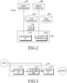
- FIG. 2 illustrates a configuration of an AR system according to an embodiment of the present disclosure.
- the system may include an AR unit 200 including an AR processing unit 210 and an AR content management unit 220.
- the AR processing unit 210 corresponds to a main unit of the system, and may receive input data from at least one of the camera unit, the media unit, the audio unit, or the sensor unit included in the electronic device 100.
- the AR processing unit 210 may use other components of the electronic device 100, e.g. a memory, a CPU, or a GPU, in order to perform AR processing for the input data.
- the AR processing unit 210 may process the input data and output data for the result obtained by processing the input data to the AR content management unit 220, by using a cache 230, a local reference DataBase (DB) 250, or a remote reference DB 270 in which reference data is stored.
- DB Local reference DataBase
- the AR processing unit 210 may process image data received from the camera unit 121, image data and audio data received from the media unit, and audio data received from the audio unit into data for the AR.
- the AR processing unit 210 may generate a vibration while converting an execution mode of the electronic device 100 into an AR mode by detecting movement of the electronic device 100 or while outputting image data and audio data in the AR mode, according to types of sensor data received from the sensor unit 122.
- the data for the result obtained by processing the input data may include recognition information and local information for the target of the input data.
- the local information may be used in order to determine a 2D pose or a 3D pose, and the recognition information may be used in order to determine types of the target.
- the AR content management unit 220 may detect contents corresponding to the data for the result obtained by processing the input data, in a local content DB 260 or a remote content DB 280, based on the data for the result obtained by processing the input data, and may configure video and audio output data based on the detected contents to output the video and audio output data.
- the AR processing unit provides input image data received through the camera unit as AR image data.
- the processor may perform the same function as that of the AR unit.
- FIG. 3 illustrates a configuration of an AR processing unit according to an embodiment of the present disclosure.
- the AR processing unit 210 may include a recognition unit 311, an initial pose calculation unit 312, and a tracking unit 313.
- Input image data may be output to the recognition unit 311 or the tracking unit 313, and the outputting may be performed by the recognition unit 311 and the tracking unit 313 in parallel.
- the recognition unit 311 may identify an object on the input image data, based on at least a part of reference image data.
- the recognition unit 311 may use reference image data stored in an internal storage device or an external storage device of the electronic device 100, in order to recognize the object.
- face recognition may need an external reference face database in order to recognize authenticated faces and recognize faces different the authenticated faces.
- QR code recognition only some specific rules are needed, and in general cases, the rules need not to be dynamically updated.
- internal reference data of the electronic device for the QR code may be provided.
- the initial pose calculation unit 312 may calculate an initial pose of an object identified through detecting an interest point in the input image data.
- the tracking unit 313 may dynamically track a change in a pose of an object in each of one or more pieces of input image data which is sequentially received through the camera unit.
- the tracking unit 313 may acquire initial information by which the initial pose of the object of the input image data may be tracked, from the initial pose calculation unit 312. Thereafter, the tracking unit 313 may dynamically calculate the change in the pose of the object by consistently tracking the object in each of the input image data received sequentially.
- the tracking unit 313 may output recognition information indicating types of the object and local information indicating the pose of the object, the object existing in the input image data received sequentially.
- the tracking unit 313 may detect an amount of movement between the image data and select one among a plurality of object tracking methods, based on at least a part of the amount of the movement, according to an embodiment of the present disclosure.
- the plurality of object tracking methods may include a first object tracking method and a second object tracking method, and the first object tracking method may require a calculation amount more than that of the second tracking method.
- the first object tracking method may include a descriptor matching method
- the second object tracking method may include a patch matching method
- the descriptor matching method corresponds to a method which extracts features irrelevant to various changes of an area around an interest point, e.g. blurring, a change in a view point, and a change in illuminance; uses the extracted features to perform matching; and is strong in rapid movement or a change in illuminance.
- Representative algorithms of the descriptor matching method may include a Scale Invariant Feature Transform (SIFT) algorithm, a Speed Up Robust Features (SURF) algorithm, a Binary Robust Independent Elementary Features (BRIEF) algorithm, etc.
- SIFT Scale Invariant Feature Transform
- SURF Speed Up Robust Features
- BRIEF Binary Robust Independent Elementary Features
- the patch matching method corresponds to a method which does not process a local area around an interest point, and performs matching by using the local area as it is, so as to have higher accuracy.
- the matching since the local area of reference image data is used as it is, the matching may be performed between the current image data and the reference image data with considerable accuracy.
- interest points of the current image data and interest points of the reference image data are accurately matched through the patch matching method, a 3D location of the reference image data to be calculated later may be accurate and a shaking level may be low.
- the patch matching method may improve a performance of the matching through performing affine warping or projective warping of the local area by using an anticipated pose.
- a matching process of the patch matching method may be performed between the reference image data and currently-input image data, or between previously-input image data and the currently-input image data.
- the tracking unit 313 may select the first object tracking method, or else the tracking unit 313 may select the second object tracking method, according to an embodiment of the present disclosure.
- the tracking unit 313 may be configured to omit the tracking of an object when the amount of the movement is equal to or similar to zero, according to an embodiment of the present disclosure.
- a configuration of the tracking unit which selects one among the plurality of object tracking methods to track an object in image data, based on at least a part of the amount of the movement, will be described below with reference to FIG. 4 .
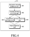
- FIG. 4 illustrates a configuration of a tracking unit for tracking an object in image data in an electronic device according to an embodiment of the present disclosure.
- the tracking unit 313 may include a pose anticipation unit (not illustrated), a movement amount estimation unit 401, a tracking method selection unit 402, a descriptor matching unit 403, a patch matching unit 404, and a pose estimation unit 405.
- the pose anticipation unit may anticipate a pose of an object in image data to be input later through a pose of an object estimated from each of one or more pieces of the previously-input input image data.
- the movement amount estimation unit 401 may measure an amount of movement of an object between currently-input image data and previously-input image data, and transmit the measured amount of the movement to the tracking method selection unit 402.
- the amount of the movement of the object may be measured in various methods.
- the amount of the movement may be obtained by phase correlation calculation using Fourier transform for the previous-input image data and the currently-input image data.
- the amount of the movement may be calculated by a change in a measurement value of a motion sensor (e.g. an accelerometer sensor, a gyro sensor, and a compass sensor) of the electronic device, and may be obtained by optical flow calculation.
- a motion sensor e.g. an accelerometer sensor, a gyro sensor, and a compass sensor
- the amount of movement may be also calculated for the whole image data, and the amount of movement data may be calculated as being limited to only an object of the whole image. Further, for example, when various interest objects are included in one image data, the amount of the movement may be separately calculated while the image data is divided into partial image data for each of the objects.
- the tracking method selection unit 402 may select the descriptor matching method as the first object tracking method, or the patch matching method as the second object tracking method, according to the amount of the movement received from the movement amount estimation unit 401.
- the tracking method selection unit 402 may omit a tracking operation for the object when the amount of the movement is equal to or similar to zero.
- the tracking method selection unit 402 may select the descriptor matching method when the amount of the movement is higher than a threshold value Mt previously selected for comparison of the amount of the movement. Further, the tracking method selection unit 402 may select the patch matching method when the amount of the movement is not higher than the previously-selected threshold value Mt.
- the tracking method selection unit 402 may select the descriptor matching method to perform a tracking operation for an object on the input image data when failing to track the object on the input image data by using the patch matching method.
- the descriptor matching unit 403 may track an object on the input image data through the descriptor matching method.
- the patch matching unit 404 may track an object on the input image data through the patch matching method.
- the pose estimation unit 405 may calculate a position and a pose of an object on the currently-input image data, based on the result obtained by performing the matching through the descriptor matching unit 403 or the patch matching unit 404.
- FIG. 5 is a flowchart illustrating an operation for tracking an object in image data in an electronic device according to an embodiment of the present disclosure.
- the movement amount estimation unit 401 may measure an amount of movement of an object between currently-input image data and previously-input image data and may transmit the measured amount to the tracking method selection unit 402, in operation 503.
- the tracking method selection unit 402 may compare the measured amount of the movement with the threshold value Mt, in operation 507. In operation 507, when it is determined that the measured amount of the movement is higher than the threshold value Mt, the tracking method selection unit 402 may request the descriptor matching unit 403 to perform an operation of tracking an object on the input image data.
- the descriptor matching unit 403 may track an object on the input image data by using the descriptor matching method, and may transmit the object tracking result to the pose estimation unit 405.
- the pose estimation unit 405 may calculate a pose of the object on the input image data, based on the object tracking result received from the descriptor matching unit 403.
- the tracking method selection unit 402 may request the patch matching unit 404 to perform an operation of tracking an object on the input image data.
- the patch matching unit 404 may track an object on the input image data through the patch matching method.
- the patch matching unit 404 informs the tracking method selection unit 402 of the failure of the object tracking. Thereafter, the tracking method selection unit 402 may request the descriptor matching unit 403 to perform an operation of tracking an object on the input image data at operation 509.
- the patch matching unit 404 may transmit the object tracking result to the pose estimation unit 405.
- the pose estimation unit 405 may calculate a pose of the object on the input image data, based on the object tracking result received from the patch matching unit 404.
- the tracking method selection unit 402 may omit the operation of tracking the object on the image data, and may transmit the measured amount of the movement to the pose estimation unit 405 at operation 511.
- the pose estimation unit 405 may calculate a pose of an object on the previously-input image data as the pose of the object on the input image data, through the measured amount of the movement received from the tracking method selection unit 402.
- the tracking unit 313 may determine whether the image data satisfies one or more first conditions and/or whether a state of the electronic device satisfies one or more second conditions, and select one among the plurality of object tracking methods, based on at least a part of the determined result, according to another embodiment of the present disclosure.
- the plurality of object tracking methods may include a first object tracking method and a second object tracking method, and the first object tracking method may require a calculation amount more than that of the second tracking method.
- the first object tracking method may include a descriptor matching method
- the second object tracking method may include a patch matching method
- the tracking unit 313 may include a configuration for determining whether an amount of movement and/or an illuminance of the image data are higher than a selected threshold value or selected threshold values, as the first condition.
- the tracking unit 313 may include a configuration for determining whether a remaining amount of electric charge of a battery included in the electronic device and/or an illuminance measured by the electronic device is higher than a selected threshold value or selected threshold values, as the second condition.
- a configuration of the tracking unit which selects one among the plurality of object tracking methods to track an object in image data, based on the first condition for the image data and the second condition for a state of the electronic device, will be described below with reference to FIG. 6 .
- FIG. 6 illustrates a configuration of a tracking unit for tracking an object in image data in an electronic device according to an embodiment of the present disclosure.
- the tracking unit 313 may include a pose anticipation unit (not illustrated), an illuminance estimation unit 601, a movement amount estimation unit 602, a battery estimation unit 603, a tracking method selection unit 604, a descriptor matching unit 605, a patch matching unit 606, and a pose estimation unit 607.
- the pose anticipation unit, the movement amount estimation unit 602, the descriptor matching unit 605, the patch matching unit 606, and the pose estimation unit 607 perform the same function as that of the pose anticipation unit, the movement amount estimation unit 401, the descriptor matching unit 403, the patch matching unit 404, and the pose estimation unit 405 illustrated in FIG. 4 , so that descriptions thereof will be omitted.
- the illuminance estimation unit 601 may illuminance which is a brightness of an environment in which image data is currently being photographed.
- the illuminance tracking unit 601 may calculate the illuminance even by a measured value of an illuminance sensor of the electronic device 100, and may calculate the illuminance even by an average value of a brightness value which is extracted from pixels constituting image data.
- the battery estimation unit 603 may measure a current remaining amount of electric charge of a battery of the electronic device 100.
- the tracking method selection unit 604 may select the descriptor matching method.
- the tracking method selection unit 604 may select the descriptor matching method.
- the tracking method selection unit 604 may select the descriptor matching method.
- the tracking method selection unit 604 may select the patch matching method.
- the tracking method selection unit 604 may select the patch matching method.
- the tracking method selection unit 604 may omit a tracking operation for the object when the amount of the movement is equal to or similar to zero.
- the tracking method selection unit 604 may select the descriptor matching method to perform a tracking operation for an object on the input image data when failing to track the object on the input image data by using the patch matching method.
- FIG. 7 is a flowchart illustrating an operation of tracking an object in image data by using a remaining amount of a battery and an amount of movement in the electronic device according to an embodiment of the present disclosure.
- the battery estimation unit 603 may measure a remaining amount of electric charge of a battery of the electronic device 100, and may transmit the measured amount to the tracking method selection unit 604, in operation 703.
- the tracking method selection unit 604 may compare the measured remaining amount of electric charge of the battery with the threshold value Bt.
- the tracking method selection unit 604 may wait to receive the amount of the movement from the movement amount estimation unit 602.
- the movement amount estimation unit 602 may measure an amount of movement of an object between currently-input image data and previously-input image data, and transmit the measured amount of the movement to the tracking method selection unit 604.
- the tracking method selection unit 604 may compare the measured amount of the movement with the threshold value Mt, in operation 711. In operation 711, when it is determined that the measured amount of the movement is higher than the threshold value Mt, the tracking method selection unit 604 may request the descriptor matching unit 605 to perform an operation of tracking an object on the input image data.
- the descriptor matching unit 605 may track an object on the input image data by using the descriptor matching method, and may transmit the object tracking result to the pose estimation unit 607.
- the pose estimation unit 607 may calculate a pose of the object on the input image data, based on the object tracking result received from the descriptor matching unit 605.
- the tracking method selection unit 604 may request the patch matching unit 606 to perform an operation of tracking an object on the input image data.
- the tracking method selection unit 604 may request the patch matching unit 606 to perform an operation of tracking an object on the input image data.
- the patch matching unit 606 may track an object on the input image data through the patch matching method.
- the patch matching unit 606 informs the tracking method selection unit 604 of the failure of the object tracking.
- the tracking method selection unit 604 may request the descriptor matching unit 605 to perform an operation of tracking an object on the input image data at operation 713.
- the patch matching unit 606 may transmit the object tracking result to the pose estimation unit 607 at operation 715.
- the pose estimation unit 607 may calculate a pose of the object on the input image data, based on the object tracking result received from the patch matching unit 606.
- the tracking method selection unit 604 may omit the operation of tracking the object on the image data, and may transmit the measured amount of the movement to the pose estimation unit 607.
- the pose estimation unit 607 may calculate a pose of an object on the previously-input image data as the pose of the object on the input image data, through the measured amount of the movement received from the tracking method selection unit 604.
- FIG. 8 is a flowchart illustrating an operation of tracking an object in image data by using an illuminance and an amount of movement in an electronic device according to an embodiment of the present disclosure.
- the illuminance estimation unit 601 may measure an illuminance which is a brightness of an environment in which image data is currently being photographed through the electronic device 100, and may transmit the measured illuminance to the tracking method selection unit 604, in operation 803.
- the tracking method selection unit 604 may compare the measured illuminance with the threshold value It.
- the tracking method selection unit 604 may wait to receive the amount of the movement from the movement amount estimation unit 602.
- the movement amount estimation unit 602 may measure an amount of movement of an object between currently-input image data and previously-input image data, and transmit the measured amount of the movement to the tracking method selection unit 604.
- the tracking method selection unit 604 may compare the measured amount of the movement with the threshold value Mt, in operation 811. In operation 811, when it is determined that the measured amount of the movement is higher than the threshold value Mt, the tracking method selection unit 604 may request the descriptor matching unit 605 to perform an operation of tracking an object on the input image data.
- the descriptor matching unit 605 may track an object on the input image data by using the descriptor matching method, and may transmit the object tracking result to the pose estimation unit 607.
- the pose estimation unit 607 may calculate a pose of the object on the input image data, based on the object tracking result received from the descriptor matching unit 605.
- the tracking method selection unit 604 may request the patch matching unit 606 to perform an operation of tracking an object on the input image data at operation 817.
- the tracking method selection unit 604 may request the patch matching unit 606 to perform an operation of tracking an object on the input image data at operation 817.
- the patch matching unit 606 may track an object on the input image data through the patch matching method.
- the patch matching unit 606 informs the tracking method selection unit 604 of the failure of the object tracking.
- the tracking method selection unit 402 may request the descriptor matching unit 605 to perform an operation of tracking an object on the input image data.
- the patch matching unit 606 may transmit the object tracking result to the pose estimation unit 607 .
- the pose estimation unit 607 may calculate a pose of the object on the input image data, based on the object tracking result received from the patch matching unit 606.
- the tracking method selection unit 604 may omit the operation of tracking the object on the image data, and may transmit the measured amount of the movement to the pose estimation unit 607.
- the pose estimation unit 607 may calculate a pose of an object on the previously-input image data as the pose of the object on the input image data, through the measured amount of the movement received from the tracking method selection unit 604.
- FIG. 9 is a flowchart illustrating an operation of tracking an object in image data by using a remaining amount of electric charge of a battery, an illuminance, and an amount of movement in an electronic device according to an embodiment of the present disclosure.
- the battery estimation unit 603 may measure a remaining amount of electric charge of a battery of the electronic device 100, and may transmit the measured amount to the tracking method selection unit 604, in operation 903.
- the tracking method selection unit 604 may compare the measured remaining amount of electric charge of the battery with the threshold value Bt.
- the tracking method selection unit 604 may wait to receive the measured illuminance from the illuminance estimation unit 601.
- the illuminance estimation unit 601 may measure an illuminance which is a brightness of an environment in which image data is currently being photographed through the electronic device 100, and may transmit the measured illuminance to the tracking method selection unit 604.
- the tracking method selection unit 604 may compare the measured illuminance with the threshold value It.
- the tracking method selection unit 604 may wait to receive the amount of the movement from the movement amount estimation unit 602.
- the movement amount estimation unit 602 may measure an amount of movement of an object between currently-input image data and previously-input image data, and transmit the measured amount of the movement to the tracking method selection unit 604.
- the tracking method selection unit 604 may compare the measured amount of the movement with the threshold value Mt, in operation 915. In operation 915, when it is determined that the measured amount of the movement is higher than the threshold value Mt, the tracking method selection unit 604 may request the descriptor matching unit 605 to perform an operation of tracking an object on the input image data.
- the descriptor matching unit 605 may track an object on the input image data by using the descriptor matching method, and may transmit the object tracking result to the pose estimation unit 607.
- the pose estimation unit 607 may calculate a pose of the object on the input image data, based on the object tracking result received from the descriptor matching unit 605.
- the tracking method selection unit 604 may request the patch matching unit 606 to perform an operation of tracking an object on the input image data at operation 921.
- the tracking method selection unit 604 may request the patch matching unit 606 to perform an operation of tracking an object on the input image data.
- the tracking method selection unit 604 may request the patch matching unit 606 to perform an operation of tracking an object on the input image data at operation 921.
- the patch matching unit 606 may track an object on the input image data through the patch matching method.
- the patch matching unit 606 informs the tracking method selection unit 604 of the failure of the object tracking.
- the tracking method selection unit 604 may request the descriptor matching unit 605 to perform an operation of tracking an object on the input image data at operation 917.
- the patch matching unit 606 may transmit the object tracking result to the pose estimation unit 607 at operation 915.
- the pose estimation unit 607 may calculate a pose of the object on the input image data, based on the object tracking result received from the patch matching unit 606.
- the tracking method selection unit 604 may omit the operation of tracking the object on the image data, and may transmit the measured amount of the movement to the pose estimation unit 607.
- the pose estimation unit 607 may calculate a pose of an object on the previously-input image data as the pose of the object on the input image data, through the measured amount of the movement received from the tracking method selection unit 604.
- the electronic device and the method of operating the electronic device according to various embodiments of the present disclosure may be realized by a computer-readable code in a computer-readable recording medium.
- the computer-readable recording medium includes all the types of recording devices in which data readable by a computer system are stored.
- a recording medium for example, a ROM, a RAM, an optical disc, a magnetic tape, a floppy disc, a hard disc, and a non-volatile memory may be used.
Landscapes
- Engineering & Computer Science (AREA)
- Multimedia (AREA)
- Computer Vision & Pattern Recognition (AREA)
- Physics & Mathematics (AREA)
- General Physics & Mathematics (AREA)
- Theoretical Computer Science (AREA)
- User Interface Of Digital Computer (AREA)
- Image Analysis (AREA)
Description
- The present disclosure relates to an electronic device and a method of operating the electronic device. More particularly, the present disclosure relates to an electronic device and a method of operating the electronic device, which can stably track an object in image data in the electronic device.
- Augmented Reality (AR) is a technology, in which a real world object viewed through a user's own eyes and a virtual object are overlapped and are then displayed. Since a video obtained by adding a virtual world, having additional information, to a real world image is shown in real time, the AR may refer to Mixed Reality (MR). Although the AR, which is a concept for complementing the real world through the virtual world, uses a virtual environment made by computer graphics, the leading role of AR is a real world environment. The computer graphics serve to additionally provide necessary information to the real world environment. The virtual reality technology allows a user to concentrate in the virtual environment, so that the user cannot see real world environment. However, the AR technology, which is implemented by mixing the real environment and a virtual object, allows a user to see the real environment, so as to provide a better sense of reality and additional information.
- Accordingly there is a need for an electronic device and a method of operating the electronic device, which can stably track an object in image data in the electronic device.
-
US 7095786 B1 discusses tracking an object in a video sequence of frames by object masks generated for frames in the sequence. - The above information is presented as background information only to assist with an understanding of the present disclosure. No determination has been made, and no assertion is made, as to whether any of the above might be applicable as prior art with regard to the present disclosure.
- Aspects of the present disclosure are to address at least the above-mentioned problems and/or disadvantages and to provide at least the advantages described below. Accordingly, an aspect of the present disclosure is to provide an electronic device and a method of operating the electronic device, which can stably track an object in image data in the electronic device.
- Augmented Reality (AR) is frequently developed for execution in a portable electronic device. Since people can easily carry the portable electronic device, situations, where an interesting object is rapidly moving, occur frequently. In this case, since blurring may occur in image data, it is difficult to track the interesting object, so that 3 Dimensional (3D) information, which is synthesized, may disappear.
- In accordance with an aspect of the present disclosure, an electronic device and a method of operating the electronic device, which can stably track an object in image data in the electronic device is provided.
- In accordance with another aspect of the present disclosure, an electronic device is provided. The electronic device includes a memory configured to store a plurality of digital images and a processor, wherein the processor tracks movement of an object recognized in the plurality of digital images, and the processor detects an amount of movement between the plurality of digital images. When the amount of the movement is greater than a threshold, the processor tracks the object on an input image using a descriptor matching method. When the amount of the movement is not greater than the threshold the processor tracks the object on the input image using a patch matching method, determines if the tracking of the object succeeds, and when the tracking the object using the patch matching method fails, the processor tracks the object on the input image data using the descriptor matching method. The descriptor matching method, using one of a Scale Invariant Feature Transform (SIFT) algorithm, a Speed Up Robust Features (SURF) algorithm, or a Binary Robust Independent Elementary Features (BRIEF) algorithm, extracts features of an area around an interest point and uses the extracted features to perform matching, and the patch matching method performs matching by using a local area around the interest point without processing the local area before performing matching.
- In accordance with another aspect of the present disclosure, a method of operating an electronic device is provided. The method includes tracking movement of an object recognized from a plurality of digital images. The tracking of the movement comprises: detecting an amount of movement between the plurality of digital images; when the amount of the movement is greater than a threshold, tracking the object on an input image using a descriptor matching method; and when the amount of the movement is not greater than the threshold, tracking the object on the input image using a patch matching method, determining if the tracking of the object succeeds, and when tracking the object using the patch matching method fails the method further comprises tracking the object on the input image data using the descriptor matching method. The descriptor matching method, using one of a Scale Invariant Feature Transform (SIFT) algorithm, a Speed Up Robust Features (SURF) algorithm, or a Binary Robust Independent Elementary Features (BRIEF) algorithm, extracts features of an area around an interest point and uses the extracted features to perform matching and the patch matching method performs matching by using a local area around the interest point without processing the local area before performing matching.
- Other aspects, advantages, and salient features of the disclosure will become apparent to those skilled in the art from the following detailed description, which, taken in conjunction with the annexed drawings, discloses various embodiments of the present disclosure.
- The above and other aspects, features, and advantages of certain embodiments of the present disclosure will be more apparent from the following description taken in conjunction with the accompanying drawings, in which:
-
FIG. 1 illustrates a configuration of an electronic device according to an embodiment of the present disclosure; -
FIG. 2 illustrates a configuration of an Augmented Reality (AR) system according to an embodiment of the present disclosure; -
FIG. 3 illustrates a configuration of an AR processing unit according to an embodiment of the present disclosure; -
FIG. 4 illustrates a configuration of a tracking unit for tracking an object in image data in an electronic device according to an embodiment of the present disclosure; -
FIG. 5 is a flowchart illustrating an operation for tracking an object in image data in an electronic device according to an embodiment of the present disclosure; -
FIG. 6 illustrates a configuration of a tracking unit for tracking an object in image data in an electronic device according to an embodiment of the present disclosure; and -
FIGS. 7 ,8 , and9 are flowcharts illustrating operations for tracking an object in image data in an electronic device according to various embodiments of the present disclosure. - Throughout the drawings, it should be noted that like reference numbers are used to depict the same or similar elements, features, and structures.
- The following description with reference with the accompanying drawings is provided to assist in a comprehensive understanding of various embodiments of the present disclosure as defined by the claims.
- The terms and words used in the following description and claims are not limited to the bibliographical meanings, but, are merely used by the inventor to enable a clear and consistent understanding of the present disclosure. Accordingly, it should be apparent to those skilled in the art that the following description of various embodiments of the present disclosure is provided for illustration purpose only and not for the purpose of limiting the present disclosure as defined by the appended claims and their equivalents.
- It is to be understood that the singular forms "a," "an," and "the" include plural referents unless the context clearly dictates otherwise. Thus, for example, reference to "a component surface" includes reference to one or more of such surfaces.
- An electronic device according to various embodiments of the present disclosure may be a device including a communication function. For example, the electronic device may be a combination of one or more of a smartphone, a tablet personal computer, a mobile phone, a video phone, an e-book reader, a desktop personal computer, a laptop personal computer, a netbook computer, a Personal Digital Assistant (PDA), a Portable Multimedia Player (PMP), an MP3 player, a mobile medical device, an electronic bracelet, an electronic necklace, an electronic appcessory, a camera, a wearable device, an electronic clock, a wrist watch, a home appliance (e.g. a refrigerator, an air conditioner, a cleaner, an oven, a microwave oven, a washing machine, a vacuum cleaner, etc.), an artificial intelligent robot, a TeleVision (TV), a Digital Video Disk (DVD) player, an audio player, various medical machines (e.g. a Magnetic Resonance Angiography (MRA), a Magnetic Resonance Imaging (MRI), a Computed Tomography (CT), a tomography camera, a ultra sonography, etc.), a navigation device, a Global Positioning System (GPS) receiver, an Event Data Recorder (EDR), a Flight Data Recorder (FDR), a set-top box, a TV box (e.g. SamSung HomeSync™, Apple TV™, or Google TV™), an electronic dictionary, a vehicle infotainment device, electronic equipment for a ship (e.g. navigation equipment for a ship, a gyrocompass, etc.), avionics equipment, a security device, an electronic cloth, an electronic key, a camcorder, a game console, a Head-Mounted Display (HMD), a flat panel display device, an electronic frame, an electronic album, a piece of furniture or a part of a building or structure including a communication function, an electronic board, an electronic signature receiving device, a wearable device, and a projector. It is obvious to those skilled in the art that the electronic device according to various embodiments of the present disclosure is not limited to the above-mentioned devices.
-
FIG. 1 illustrates a configuration of an electronic device 100 according to an embodiment of the present disclosure. - Referring to
FIG. 1 , apower supply unit 110 may supply electric power to one or a plurality of batteries (not illustrated) disposed in a housing of the electronic device 100 under the control of a powersupply management unit 111. The one or more batteries (not illustrated) may supply electric power to the electronic device 100. - Further, the
power supply unit 110 may supply electric power input from an external power source (not illustrated) through a wired cable connected to a connector of the electronic device 100. Further, thepower supply unit 110 may supply electric power wirelessly input from the external power source through a wireless charging technology, to the electronic device 100. - The power
supply management unit 111 may perform a control to supply electric power of thepower supply unit 110 to the electronic device 100, or to supply electric power input from the external power source to thepower supply unit 110, under the control of aprocessor 115. - A
communication unit 112 allows the electronic device 100 to be connected to an external device through mobile communication by using one or a plurality of antennas (not illustrated) under the control of theprocessor 115. - The
communication unit 112 may include at least one of a wireless Local Area Network (LAN) unit and a short distance communication unit. For example, thecommunication unit 112 may include only the wireless LAN unit, only the short distance communication unit, or both the wireless LAN unit and the short distance communication unit. The wireless LAN unit may access the Internet in a place where a wireless Access Point (AP) (not illustrated) is installed, under the control of theprocessor 115. The wireless LAN unit may support a wireless LAN standard IEEE802.11x of the Institute of Electrical and Electronics Engineers (IEEE). The short distance communication unit may wirelessly perform short distance communication under the control of theprocessor 115. The short distance communication scheme may include Bluetooth, Infrared Data Association (IrDA) communication, WiFi-Direct communication, Near Field Communication (NFC), etc. - The
communication unit 112 may include a GPS unit, and the GPS unit may calculate a location of the electronic device 100 by receiving a radio wave from a plurality of GPS satellites (not illustrated) in Earth's orbit and using times of arrival from the GPS satellites (not illustrated) to the electronic device 100. - An
RF unit 113 may transmit/receive a wireless signal for voice call, video call, a Short Message Service (SMS), or Multimedia Message Service (MMS) to/from a portable phone (not illustrated), a smart phone (not illustrated), a tablet PC, or other devices (not illustrated) of which the phone number is input to the electronic device 100. - The
processor 115 may include a Read-Only Memory (ROM) for storing a control program for controlling a Central Processing Unit (CPU), a Graphics Processing Unit (GPU), and the electronic device 100, and a Random Access Memory (RAM) for storing a signal or data input from the outside of the electronic device 100 or being used as a memory area for an operation performed in the electronic device 100. The CPU may include a single core, a dual core, a triple core, or a quadruple core. The CPU, the ROM, and the RAM may be connected with each other through internal buses. - The
processor 115 may control thepower supply unit 110, the powersupply management unit 111, thecommunication unit 112, theRF unit 113, afirst memory 116, asecond memory 117, anaudio processing unit 118, aninput unit 119, adisplay unit 120, acamera unit 121, and asensor unit 122. - The
processor 115 may include an Augmented Reality (AR)unit 200 for processing input data into AR data, and theAR unit 200 may not be included in theprocessor 115 and may be separately configured. A configuration of theAR unit 200 will be described in detail below with reference toFIGS. 2 to 5 . - The
processor 115 may process image data stored in thefirst memory 116 into 3D image data which can be displayed in an AR mode, according to various embodiments of the present disclosure. - The
processor 115 may detect an amount of movement between the image data, and select one among a plurality of object tracking methods, based on at least a part of the amount of the movement, according to an embodiment of the present disclosure. - The plurality of object tracking methods may include a first object tracking method and a second object tracking method, and the first object tracking method may require a calculation amount more than that of the second tracking method.
- In various embodiments of the present disclosure, the first object tracking method may include a descriptor matching method, and the second object tracking method may include a patch matching method.
- The
processor 115 may be configured to omit the tracking of an object when the amount of the movement is equal to or similar to zero, according to various embodiments of the present disclosure. - The
processor 115 may determine whether the image data satisfies one or more first conditions and/or whether a state of the electronic device satisfies one or more second conditions, and select one among the plurality of object tracking methods, based on at least a part of the determined result, according to another embodiment of the present disclosure. - The
processor 115 may include a configuration for determining whether an amount of movement and/or an illuminance of the image data are higher than a selected threshold value or selected threshold values, as the first condition, according to another embodiment of the present disclosure. - The
processor 115 may include a configuration for determining whether a remaining amount of electric charge of a battery included in the electronic device and/or an illuminance measured by the electronic device is higher than a selected threshold value or selected threshold values, as the second condition, according to another embodiment of the present disclosure. - The
first memory 116 may store a signal or data input/output in correspondence with operations of thecommunication unit 112, theRF unit 113, theinput unit 119, thecamera unit 121, thesensor unit 122, and thedisplay unit 120 used as a touch screen unit, under the control of theprocessor 115. Thefirst memory 116 may store a control program for controlling the electronic device 100 or theprocessor 115, and applications. Thefirst memory 116 may store digital image data. - The
second memory 117 corresponds to an external memory which can be extracted from or inserted into the electronic device 100, and may store a signal or data input/output in correspondence with operations of thecommunication unit 112, theRF unit 113, theinput unit 119, thecamera unit 121, thesensor unit 122, and thedisplay unit 120 used as a touch screen unit, under the control of theprocessor 115. - The
audio processing unit 118 may include a transmitter for encoding and modulating a signal to be transmitted and a receiver for decoding and demodulating a signal to be received, and may be configured by a Modulator/Demodulator (MODEM) and a Coder/Decoder (CODEC). The CODEC may include a data CODEC for processing packet data and an audio CODEC for processing an audio signal such as voice. Theaudio processing unit 118 may output a reception audio signal output from the audio CODEC to a speaker or an earphone connected to the electronic device, or may transmit a transmission audio signal generated by a microphone or a receiver to theprocessor 115 through the audio CODEC. - The
input unit 119 may perform a touch input which is input to the display unit used as the touch screen unit by a user and a touch input using a touch pen. - The
input unit 119 may receive a key input from a user in order to control the electronic device 100. Theinput unit 119 may include a physical keypad (not illustrated) formed in the electronic device 100 and a virtual keypad (not illustrated) displayed on thedisplay unit 120 used as the touch screen unit. The physical keypad (not illustrated) formed in the electronic device 100 may be excluded according to a performance or a structure of the electronic device 100. - The
display unit 120 may employ a Liquid Crystal Display (LCD) panel, in which case thedisplay unit 120 may include an LCD controller, a memory for storing video data, an LCD element, etc. When the LCD is realized in a touch screen scheme, thedisplay unit 120 may operate as an input unit, and at this time, a virtual keypad may be displayed on thedisplay unit 120. Further, when thedisplay unit 120 is realized in the touch screen scheme so that thedisplay unit 120 is used as the touch screen unit, the touch screen unit may be formed by a Touch Screen Panel (TSP) including a plurality of sensor panels, and the plurality of sensor panels may include a capacitive sensor panel which can recognize a hand touch and an electromagnetic sensor panel which can detect a minute touch of a touch pen. - The
camera unit 121 corresponds to a device for generating an image, and may include at least one of a first camera and a second camera for photographing a still image or video under the control of theprocessor 115. Further, the first camera or the second camera may include an auxiliary light source (e.g. a flash (not illustrated)) for providing an amount of light needed for photographing. The first camera may be disposed on a front surface of the electronic device 100, and the second camera may be disposed on a rear surface of the electronic device 100. As another scheme, the first camera and the second camera are disposed adjacent to each other (e.g. a space between the first camera and the second camera is wider than 1 cm and narrower than 8 cm), so as to photograph a 3D still image or a 3D video. - The
sensor unit 122 may include at least one sensor for detecting a state of the electronic device 100. For example, thesensor unit 122 may include a proximity sensor for detecting whether a user approaches the electronic device 100, an illumination sensor (not illustrated) for detecting an amount of ambient light of the electronic device 100, a motion sensor (not illustrated) for detecting an operation (e.g. a rotation of the electronic device 100, or an acceleration or a vibration applied to the electronic device 00) of the electronic device 100, a geo-magnetic sensor (not illustrated) for detecting a point of the compass by using the Earth's magnetic field, a gravity sensor for detecting an action direction of the gravity, or an altimeter for measuring an atmospheric pressure to detect an altitude. At least one sensor may detect the state, generate a signal corresponding to the detection, and transmit the generated signal to theprocessor 115. The sensors of thesensor unit 122 may be added or deleted according to the performance of the electronic device 100. -
FIG. 2 illustrates a configuration of an AR system according to an embodiment of the present disclosure. - Referring to
FIG. 2 , the system may include anAR unit 200 including anAR processing unit 210 and an ARcontent management unit 220. - The
AR processing unit 210 corresponds to a main unit of the system, and may receive input data from at least one of the camera unit, the media unit, the audio unit, or the sensor unit included in the electronic device 100. TheAR processing unit 210 may use other components of the electronic device 100, e.g. a memory, a CPU, or a GPU, in order to perform AR processing for the input data. In order to recognize a target in the input data, theAR processing unit 210 may process the input data and output data for the result obtained by processing the input data to the ARcontent management unit 220, by using acache 230, a local reference DataBase (DB) 250, or aremote reference DB 270 in which reference data is stored. - The
AR processing unit 210 may process image data received from thecamera unit 121, image data and audio data received from the media unit, and audio data received from the audio unit into data for the AR. TheAR processing unit 210 may generate a vibration while converting an execution mode of the electronic device 100 into an AR mode by detecting movement of the electronic device 100 or while outputting image data and audio data in the AR mode, according to types of sensor data received from thesensor unit 122. - The data for the result obtained by processing the input data may include recognition information and local information for the target of the input data.
- When the target is image data, the local information may be used in order to determine a 2D pose or a 3D pose, and the recognition information may be used in order to determine types of the target.
- The AR
content management unit 220 may detect contents corresponding to the data for the result obtained by processing the input data, in alocal content DB 260 or aremote content DB 280, based on the data for the result obtained by processing the input data, and may configure video and audio output data based on the detected contents to output the video and audio output data. - In various embodiments of the present disclosure, it may be described as an example that the AR processing unit provides input image data received through the camera unit as AR image data.
- In the electronic device according to various embodiments of the present disclosure, although it has been described as an example that the AR unit included in the processor performs AR processing, the processor may perform the same function as that of the AR unit.
-
FIG. 3 illustrates a configuration of an AR processing unit according to an embodiment of the present disclosure. - Referring to
FIG. 3 , theAR processing unit 210 may include arecognition unit 311, an initialpose calculation unit 312, and atracking unit 313. Input image data may be output to therecognition unit 311 or thetracking unit 313, and the outputting may be performed by therecognition unit 311 and thetracking unit 313 in parallel. - The
recognition unit 311 may identify an object on the input image data, based on at least a part of reference image data. Therecognition unit 311 may use reference image data stored in an internal storage device or an external storage device of the electronic device 100, in order to recognize the object. For example, face recognition may need an external reference face database in order to recognize authenticated faces and recognize faces different the authenticated faces. - Meanwhile, generally, for QR code recognition, only some specific rules are needed, and in general cases, the rules need not to be dynamically updated. Thus, internal reference data of the electronic device for the QR code may be provided.
- The initial
pose calculation unit 312 may calculate an initial pose of an object identified through detecting an interest point in the input image data. - The
tracking unit 313 may dynamically track a change in a pose of an object in each of one or more pieces of input image data which is sequentially received through the camera unit. - The
tracking unit 313 may acquire initial information by which the initial pose of the object of the input image data may be tracked, from the initialpose calculation unit 312. Thereafter, thetracking unit 313 may dynamically calculate the change in the pose of the object by consistently tracking the object in each of the input image data received sequentially. - The
tracking unit 313 may output recognition information indicating types of the object and local information indicating the pose of the object, the object existing in the input image data received sequentially. - The
tracking unit 313 may detect an amount of movement between the image data and select one among a plurality of object tracking methods, based on at least a part of the amount of the movement, according to an embodiment of the present disclosure. - The plurality of object tracking methods may include a first object tracking method and a second object tracking method, and the first object tracking method may require a calculation amount more than that of the second tracking method.
- In various embodiments of the present disclosure, the first object tracking method may include a descriptor matching method, and the second object tracking method may include a patch matching method.
- The descriptor matching method corresponds to a method which extracts features irrelevant to various changes of an area around an interest point, e.g. blurring, a change in a view point, and a change in illuminance; uses the extracted features to perform matching; and is strong in rapid movement or a change in illuminance.
- Representative algorithms of the descriptor matching method may include a Scale Invariant Feature Transform (SIFT) algorithm, a Speed Up Robust Features (SURF) algorithm, a Binary Robust Independent Elementary Features (BRIEF) algorithm, etc. In the descriptor matching method, since the reference image data is processed to be strong in various changes, the matching may be performed at a correct location between current image data and reference image data or a peripheral location therebetween.
- The patch matching method corresponds to a method which does not process a local area around an interest point, and performs matching by using the local area as it is, so as to have higher accuracy. In the patch matching method, since the local area of reference image data is used as it is, the matching may be performed between the current image data and the reference image data with considerable accuracy. When interest points of the current image data and interest points of the reference image data are accurately matched through the patch matching method, a 3D location of the reference image data to be calculated later may be accurate and a shaking level may be low. The patch matching method may improve a performance of the matching through performing affine warping or projective warping of the local area by using an anticipated pose.
- A matching process of the patch matching method may be performed between the reference image data and currently-input image data, or between previously-input image data and the currently-input image data.
- When the amount of the movement is higher than a first threshold value, the
tracking unit 313 may select the first object tracking method, or else thetracking unit 313 may select the second object tracking method, according to an embodiment of the present disclosure. - The
tracking unit 313 may be configured to omit the tracking of an object when the amount of the movement is equal to or similar to zero, according to an embodiment of the present disclosure. - A configuration of the tracking unit, which selects one among the plurality of object tracking methods to track an object in image data, based on at least a part of the amount of the movement, will be described below with reference to
FIG. 4 . -
FIG. 4 illustrates a configuration of a tracking unit for tracking an object in image data in an electronic device according to an embodiment of the present disclosure. - Referring to
FIG. 4 , thetracking unit 313 may include a pose anticipation unit (not illustrated), a movementamount estimation unit 401, a trackingmethod selection unit 402, adescriptor matching unit 403, apatch matching unit 404, and apose estimation unit 405. - The pose anticipation unit may anticipate a pose of an object in image data to be input later through a pose of an object estimated from each of one or more pieces of the previously-input input image data.
- The movement
amount estimation unit 401 may measure an amount of movement of an object between currently-input image data and previously-input image data, and transmit the measured amount of the movement to the trackingmethod selection unit 402. The amount of the movement of the object may be measured in various methods. For example, the amount of the movement may be obtained by phase correlation calculation using Fourier transform for the previous-input image data and the currently-input image data. Further, for example, the amount of the movement may be calculated by a change in a measurement value of a motion sensor (e.g. an accelerometer sensor, a gyro sensor, and a compass sensor) of the electronic device, and may be obtained by optical flow calculation. Further, for example, when a measurement value is obtained by calculation using image data, the amount of movement may be also calculated for the whole image data, and the amount of movement data may be calculated as being limited to only an object of the whole image. Further, for example, when various interest objects are included in one image data, the amount of the movement may be separately calculated while the image data is divided into partial image data for each of the objects. - The tracking
method selection unit 402 may select the descriptor matching method as the first object tracking method, or the patch matching method as the second object tracking method, according to the amount of the movement received from the movementamount estimation unit 401. - The tracking
method selection unit 402 may omit a tracking operation for the object when the amount of the movement is equal to or similar to zero. The trackingmethod selection unit 402 may select the descriptor matching method when the amount of the movement is higher than a threshold value Mt previously selected for comparison of the amount of the movement. Further, the trackingmethod selection unit 402 may select the patch matching method when the amount of the movement is not higher than the previously-selected threshold value Mt. - The tracking
method selection unit 402 may select the descriptor matching method to perform a tracking operation for an object on the input image data when failing to track the object on the input image data by using the patch matching method. - The
descriptor matching unit 403 may track an object on the input image data through the descriptor matching method. - The
patch matching unit 404 may track an object on the input image data through the patch matching method. - The
pose estimation unit 405 may calculate a position and a pose of an object on the currently-input image data, based on the result obtained by performing the matching through thedescriptor matching unit 403 or thepatch matching unit 404. - An operation of tracking an object in image data in the electronic device including the tracking unit illustrated in
FIG. 4 will be described in detail with reference toFIG. 5 . -
FIG. 5 is a flowchart illustrating an operation for tracking an object in image data in an electronic device according to an embodiment of the present disclosure. - Referring to
FIG. 5 , when image data is input inoperation 501, the movementamount estimation unit 401 may measure an amount of movement of an object between currently-input image data and previously-input image data and may transmit the measured amount to the trackingmethod selection unit 402, inoperation 503. - When it is determined in
operation 505 that the measured amount of the movement is not equal to or similar to zero, the trackingmethod selection unit 402 may compare the measured amount of the movement with the threshold value Mt, inoperation 507. Inoperation 507, when it is determined that the measured amount of the movement is higher than the threshold value Mt, the trackingmethod selection unit 402 may request thedescriptor matching unit 403 to perform an operation of tracking an object on the input image data. - In
operation 509, thedescriptor matching unit 403 may track an object on the input image data by using the descriptor matching method, and may transmit the object tracking result to thepose estimation unit 405. - In
operation 511, thepose estimation unit 405 may calculate a pose of the object on the input image data, based on the object tracking result received from thedescriptor matching unit 403. - In
operation 507, when it is determined that the measured amount of the movement is not higher than the threshold value Mt, the trackingmethod selection unit 402 may request thepatch matching unit 404 to perform an operation of tracking an object on the input image data. - In
operation 513, thepatch matching unit 404 may track an object on the input image data through the patch matching method. Inoperation 515, when it is determined that the tracking of the object on the image data using the patch matching method fails, thepatch matching unit 404 informs the trackingmethod selection unit 402 of the failure of the object tracking. Thereafter, the trackingmethod selection unit 402 may request thedescriptor matching unit 403 to perform an operation of tracking an object on the input image data atoperation 509. - In
operation 515, when it is determined that the tracking of the object on the image data using the patch matching method succeeds, thepatch matching unit 404 may transmit the object tracking result to thepose estimation unit 405. - In
operation 511, thepose estimation unit 405 may calculate a pose of the object on the input image data, based on the object tracking result received from thepatch matching unit 404. - In
operation 505, when it is determined that the measured amount of the movement is equal to or similar to zero, the trackingmethod selection unit 402 may omit the operation of tracking the object on the image data, and may transmit the measured amount of the movement to thepose estimation unit 405 atoperation 511. Inoperation 511, thepose estimation unit 405 may calculate a pose of an object on the previously-input image data as the pose of the object on the input image data, through the measured amount of the movement received from the trackingmethod selection unit 402. - The
tracking unit 313 may determine whether the image data satisfies one or more first conditions and/or whether a state of the electronic device satisfies one or more second conditions, and select one among the plurality of object tracking methods, based on at least a part of the determined result, according to another embodiment of the present disclosure. - The plurality of object tracking methods may include a first object tracking method and a second object tracking method, and the first object tracking method may require a calculation amount more than that of the second tracking method.
- In various embodiments of the present disclosure, the first object tracking method may include a descriptor matching method, and the second object tracking method may include a patch matching method.
- The
tracking unit 313 may include a configuration for determining whether an amount of movement and/or an illuminance of the image data are higher than a selected threshold value or selected threshold values, as the first condition. - The
tracking unit 313 may include a configuration for determining whether a remaining amount of electric charge of a battery included in the electronic device and/or an illuminance measured by the electronic device is higher than a selected threshold value or selected threshold values, as the second condition. - A configuration of the tracking unit, which selects one among the plurality of object tracking methods to track an object in image data, based on the first condition for the image data and the second condition for a state of the electronic device, will be described below with reference to
FIG. 6 . -
FIG. 6 illustrates a configuration of a tracking unit for tracking an object in image data in an electronic device according to an embodiment of the present disclosure. - Referring to
FIG. 6 , thetracking unit 313 may include a pose anticipation unit (not illustrated), anilluminance estimation unit 601, a movementamount estimation unit 602, abattery estimation unit 603, a trackingmethod selection unit 604, adescriptor matching unit 605, apatch matching unit 606, and apose estimation unit 607. - The pose anticipation unit, the movement
amount estimation unit 602, thedescriptor matching unit 605, thepatch matching unit 606, and thepose estimation unit 607 perform the same function as that of the pose anticipation unit, the movementamount estimation unit 401, thedescriptor matching unit 403, thepatch matching unit 404, and thepose estimation unit 405 illustrated inFIG. 4 , so that descriptions thereof will be omitted. - The
illuminance estimation unit 601 may illuminance which is a brightness of an environment in which image data is currently being photographed. Theilluminance tracking unit 601 may calculate the illuminance even by a measured value of an illuminance sensor of the electronic device 100, and may calculate the illuminance even by an average value of a brightness value which is extracted from pixels constituting image data. - The
battery estimation unit 603 may measure a current remaining amount of electric charge of a battery of the electronic device 100. - When the remaining amount of electric charge of the battery measured through the
battery estimation unit 603 is higher than a threshold value Bt previously selected for comparison of remaining amounts of electric charge of batteries, and an amount of movement of an object in the currently-input image data measured through the movementamount estimation unit 602 is higher than a threshold value Mt previously selected for comparison of amounts of movement, the trackingmethod selection unit 604 may select the descriptor matching method. - When the illuminance measured through the
illuminance estimation unit 601 is higher than a threshold value It previously selected for comparison of illuminance, and an amount of movement of an object on the currently-input image data measured through the movementamount estimation unit 602 is higher than a threshold value Mt previously selected for comparison of amounts of movement, the trackingmethod selection unit 604 may select the descriptor matching method. - When the remaining amount of electric charge of the battery measured through the
battery estimation unit 603 is higher than a threshold value Bt previously selected for comparison of remaining amounts of electric charge of batteries, the illuminance measured through theilluminance estimation unit 601 is higher than a threshold value It previously selected for comparison of illuminance, and the amount of movement of an object on the currently-input image data measured through the movementamount estimation unit 602 is higher than a threshold value Mt previously selected for comparison of amounts of movement, the trackingmethod selection unit 604 may select the descriptor matching method. - When the remaining amount of electric charge of the battery measured through the
battery estimation unit 603 is not higher than the threshold value Bt, or the amount of the movement measured through the movementamount estimation unit 602 is not higher than the threshold value Mt, the trackingmethod selection unit 604 may select the patch matching method. - When the remaining amount of electric charge of the battery measured through the
battery estimation unit 603 is not higher than the threshold value Bt, the illuminance measured through theilluminance estimation unit 601 is not higher than the threshold value IT, or the amount of the movement measured through the movementamount estimation unit 602 is not higher than the threshold value Mt, the trackingmethod selection unit 604 may select the patch matching method. - The tracking
method selection unit 604 may omit a tracking operation for the object when the amount of the movement is equal to or similar to zero. - The tracking
method selection unit 604 may select the descriptor matching method to perform a tracking operation for an object on the input image data when failing to track the object on the input image data by using the patch matching method. - An operation of tracking an object in image data in the electronic device including the tracking unit illustrated in
FIG. 6 will be described in detail with reference toFIGS. 7 to 9 . -
FIG. 7 is a flowchart illustrating an operation of tracking an object in image data by using a remaining amount of a battery and an amount of movement in the electronic device according to an embodiment of the present disclosure. - Referring to
FIG. 7 , when image data is input inoperation 701, thebattery estimation unit 603 may measure a remaining amount of electric charge of a battery of the electronic device 100, and may transmit the measured amount to the trackingmethod selection unit 604, inoperation 703. - In
operation 705, the trackingmethod selection unit 604 may compare the measured remaining amount of electric charge of the battery with the threshold value Bt. - In
operation 705, when the measured remaining amount of electric charge of the battery is higher than the threshold value Bt, the trackingmethod selection unit 604 may wait to receive the amount of the movement from the movementamount estimation unit 602. - In
operation 707, the movementamount estimation unit 602 may measure an amount of movement of an object between currently-input image data and previously-input image data, and transmit the measured amount of the movement to the trackingmethod selection unit 604. - When it is determined in
operation 709 that the measured amount of the movement is not equal to or similar to zero, the trackingmethod selection unit 604 may compare the measured amount of the movement with the threshold value Mt, inoperation 711. Inoperation 711, when it is determined that the measured amount of the movement is higher than the threshold value Mt, the trackingmethod selection unit 604 may request thedescriptor matching unit 605 to perform an operation of tracking an object on the input image data. - In
operation 713, thedescriptor matching unit 605 may track an object on the input image data by using the descriptor matching method, and may transmit the object tracking result to thepose estimation unit 607. - In
operation 715, thepose estimation unit 607 may calculate a pose of the object on the input image data, based on the object tracking result received from thedescriptor matching unit 605. - In
operation 705, when it is determined that the measured remaining amount of electric charge of the battery is not higher than the threshold value Bt, the trackingmethod selection unit 604 may request thepatch matching unit 606 to perform an operation of tracking an object on the input image data. - Further, in
operation 711, when it is determined that the measured amount of the movement is not higher than the threshold value Mt, the trackingmethod selection unit 604 may request thepatch matching unit 606 to perform an operation of tracking an object on the input image data. - In
operation 717, thepatch matching unit 606 may track an object on the input image data through the patch matching method. - In
operation 719, when it is determined that the tracking of the object on the image data using the patch matching method fails, thepatch matching unit 606 informs the trackingmethod selection unit 604 of the failure of the object tracking. - Thereafter, the tracking
method selection unit 604 may request thedescriptor matching unit 605 to perform an operation of tracking an object on the input image data atoperation 713. - In
operation 719, when it is determined that the tracking of the object on the image data using the patch matching method succeeds, thepatch matching unit 606 may transmit the object tracking result to thepose estimation unit 607 atoperation 715. - In
operation 715, thepose estimation unit 607 may calculate a pose of the object on the input image data, based on the object tracking result received from thepatch matching unit 606. - In
operation 709, when it is determined that the measured amount of the movement is equal to or similar to zero, the trackingmethod selection unit 604 may omit the operation of tracking the object on the image data, and may transmit the measured amount of the movement to thepose estimation unit 607. Inoperation 715, thepose estimation unit 607 may calculate a pose of an object on the previously-input image data as the pose of the object on the input image data, through the measured amount of the movement received from the trackingmethod selection unit 604. -
FIG. 8 is a flowchart illustrating an operation of tracking an object in image data by using an illuminance and an amount of movement in an electronic device according to an embodiment of the present disclosure. - Referring to
FIG. 8 , when image data is input inoperation 801, theilluminance estimation unit 601 may measure an illuminance which is a brightness of an environment in which image data is currently being photographed through the electronic device 100, and may transmit the measured illuminance to the trackingmethod selection unit 604, inoperation 803. - In
operation 805, the trackingmethod selection unit 604 may compare the measured illuminance with the threshold value It. - In
operation 805, when the measured illuminance is not higher than the threshold value It, the trackingmethod selection unit 604 may wait to receive the amount of the movement from the movementamount estimation unit 602. - In
operation 807, the movementamount estimation unit 602 may measure an amount of movement of an object between currently-input image data and previously-input image data, and transmit the measured amount of the movement to the trackingmethod selection unit 604. - When it is determined in
operation 809 that the measured amount of the movement is not equal to or similar to zero, the trackingmethod selection unit 604 may compare the measured amount of the movement with the threshold value Mt, inoperation 811. Inoperation 811, when it is determined that the measured amount of the movement is higher than the threshold value Mt, the trackingmethod selection unit 604 may request thedescriptor matching unit 605 to perform an operation of tracking an object on the input image data. - In
operation 813, thedescriptor matching unit 605 may track an object on the input image data by using the descriptor matching method, and may transmit the object tracking result to thepose estimation unit 607. - In
operation 815, thepose estimation unit 607 may calculate a pose of the object on the input image data, based on the object tracking result received from thedescriptor matching unit 605. - In
operation 805, when it is determined that the measured illuminance is higher than the threshold value It, the trackingmethod selection unit 604 may request thepatch matching unit 606 to perform an operation of tracking an object on the input image data atoperation 817. - Further, in
operation 811, when it is determined that the measured amount of the movement is not higher than the threshold value Mt, the trackingmethod selection unit 604 may request thepatch matching unit 606 to perform an operation of tracking an object on the input image data atoperation 817. - In
operation 817, thepatch matching unit 606 may track an object on the input image data through the patch matching method. - In
operation 819, when it is determined that the tracking of the object on the image data using the patch matching method fails, thepatch matching unit 606 informs the trackingmethod selection unit 604 of the failure of the object tracking. - Thereafter, the tracking
method selection unit 402 may request thedescriptor matching unit 605 to perform an operation of tracking an object on the input image data. - In
operation 819, when it is determined that the tracking of the object on the image data using the patch matching method succeeds, thepatch matching unit 606 may transmit the object tracking result to thepose estimation unit 607 . - In
operation 815, thepose estimation unit 607 may calculate a pose of the object on the input image data, based on the object tracking result received from thepatch matching unit 606. - In
operation 809, when it is determined that the measured amount of the movement is equal to or similar to zero, the trackingmethod selection unit 604 may omit the operation of tracking the object on the image data, and may transmit the measured amount of the movement to thepose estimation unit 607. Inoperation 815, thepose estimation unit 607 may calculate a pose of an object on the previously-input image data as the pose of the object on the input image data, through the measured amount of the movement received from the trackingmethod selection unit 604. -
FIG. 9 is a flowchart illustrating an operation of tracking an object in image data by using a remaining amount of electric charge of a battery, an illuminance, and an amount of movement in an electronic device according to an embodiment of the present disclosure. - Referring to
FIG. 9 , when image data is input inoperation 901, thebattery estimation unit 603 may measure a remaining amount of electric charge of a battery of the electronic device 100, and may transmit the measured amount to the trackingmethod selection unit 604, inoperation 903. - In
operation 905, the trackingmethod selection unit 604 may compare the measured remaining amount of electric charge of the battery with the threshold value Bt. - In
operation 905, when the measured remaining amount of electric charge of the battery is higher than the threshold value Bt, the trackingmethod selection unit 604 may wait to receive the measured illuminance from theilluminance estimation unit 601. - In
operation 907, theilluminance estimation unit 601 may measure an illuminance which is a brightness of an environment in which image data is currently being photographed through the electronic device 100, and may transmit the measured illuminance to the trackingmethod selection unit 604. - In
operation 909, the trackingmethod selection unit 604 may compare the measured illuminance with the threshold value It. - In
operation 909, when it is determined that the measured illuminance is not higher than the threshold value It, the trackingmethod selection unit 604 may wait to receive the amount of the movement from the movementamount estimation unit 602. - In
operation 911, the movementamount estimation unit 602 may measure an amount of movement of an object between currently-input image data and previously-input image data, and transmit the measured amount of the movement to the trackingmethod selection unit 604. - When it is determined in
operation 913 that the measured amount of the movement is not equal to or similar to zero, the trackingmethod selection unit 604 may compare the measured amount of the movement with the threshold value Mt, inoperation 915. Inoperation 915, when it is determined that the measured amount of the movement is higher than the threshold value Mt, the trackingmethod selection unit 604 may request thedescriptor matching unit 605 to perform an operation of tracking an object on the input image data. - In
operation 917, thedescriptor matching unit 605 may track an object on the input image data by using the descriptor matching method, and may transmit the object tracking result to thepose estimation unit 607. - In
operation 919, thepose estimation unit 607 may calculate a pose of the object on the input image data, based on the object tracking result received from thedescriptor matching unit 605. - In
operation 905, when it is determined that the measured remaining amount of electric charge of the battery is not higher than the threshold value Bt, the trackingmethod selection unit 604 may request thepatch matching unit 606 to perform an operation of tracking an object on the input image data atoperation 921. - Further, in
operation 909, when it is determined that the measured illuminance is higher than the threshold value It, the trackingmethod selection unit 604 may request thepatch matching unit 606 to perform an operation of tracking an object on the input image data. - Further, in
operation 915, when it is determined that the measured amount of the movement is not higher than the threshold value Mt, the trackingmethod selection unit 604 may request thepatch matching unit 606 to perform an operation of tracking an object on the input image data atoperation 921. - In
operation 921, thepatch matching unit 606 may track an object on the input image data through the patch matching method. - In
operation 923, when it is determined that the tracking of the object on the image data using the patch matching method fails, thepatch matching unit 606 informs the trackingmethod selection unit 604 of the failure of the object tracking. - Thereafter, the tracking
method selection unit 604 may request thedescriptor matching unit 605 to perform an operation of tracking an object on the input image data atoperation 917. - In
operation 923, when it is determined that the tracking of the object on the image data using the patch matching method succeeds, thepatch matching unit 606 may transmit the object tracking result to thepose estimation unit 607 atoperation 915. - In
operation 919, thepose estimation unit 607 may calculate a pose of the object on the input image data, based on the object tracking result received from thepatch matching unit 606. - In
operation 913, when it is determined that the measured amount of the movement is equal to or similar to zero, the trackingmethod selection unit 604 may omit the operation of tracking the object on the image data, and may transmit the measured amount of the movement to thepose estimation unit 607. Inoperation 919, thepose estimation unit 607 may calculate a pose of an object on the previously-input image data as the pose of the object on the input image data, through the measured amount of the movement received from the trackingmethod selection unit 604. - The electronic device and the method of operating the electronic device according to various embodiments of the present disclosure may be realized by a computer-readable code in a computer-readable recording medium. The computer-readable recording medium includes all the types of recording devices in which data readable by a computer system are stored. As for such a recording medium, for example, a ROM, a RAM, an optical disc, a magnetic tape, a floppy disc, a hard disc, and a non-volatile memory may be used.
- The invention is set out in the appended set of claims.
Claims (2)
- An electronic device (100) comprising:a memory (116, 117) configured to store a plurality of digital images; anda processor (115),wherein the processor tracks movement of an object recognized in the plurality of digital images, and
the processor detects an amount of movement between the plurality of digital images,
wherein when the amount of the movement is greater than a threshold, the processor tracks the object on an input image using a descriptor matching method,
wherein when the amount of the movement is not greater than the threshold, the processor tracks the object on the input image using a patch matching method, determines if the tracking of the object succeeds, and when the tracking the object using the patch matching method fails, the processor tracks the object on the input image data using the descriptor matching method, and
wherein the descriptor matching method, using one of a Scale Invariant Feature Transform, SIFT, algorithm, a Speed Up Robust Features, SURF, algorithm, or a Binary Robust Independent Elementary Features, BRIEF, algorithm, extracts features of an area around an interest point and uses the extracted features to perform matching, and the patch matching method performs matching by using a local area around the interest point without processing the local area before performing matching. - A method of operating an electronic device, the method comprising:
tracking movement of an object recognized from a plurality of digital images (503),
wherein the tracking of the movement comprises:detecting an amount of movement between the plurality of digital images;when the amount of the movement is greater than a threshold (507), tracking the object on an input image using a descriptor matching method (509); andwhen the amount of the movement is not greater than the threshold (507), tracking the object on the input image using a patch matching method (513), determining if the tracking of the object succeeds (515), and when tracking the object using the patch matching method fails the method further comprises tracking the object on the input image data using the descriptor matching method (509),wherein the descriptor matching method, using one of a Scale Invariant Feature Transform, SIFT, algorithm, a Speed Up Robust Features, SURF, algorithm, or a Binary Robust Independent Elementary Features, BRIEF, algorithm, extracts features of an area around an interest point and uses the extracted features to perform matching, and the patch matching method performs matching by using a local area around the interest point without processing the local area before performing matching.
Applications Claiming Priority (2)
| Application Number | Priority Date | Filing Date | Title |
|---|---|---|---|
| US201361767406P | 2013-02-21 | 2013-02-21 | |
| KR1020130166600A KR102223313B1 (en) | 2013-02-21 | 2013-12-30 | Electronic device and method for operating an electronic device |
Publications (3)
| Publication Number | Publication Date |
|---|---|
| EP2770479A2 EP2770479A2 (en) | 2014-08-27 |
| EP2770479A3 EP2770479A3 (en) | 2017-08-09 |
| EP2770479B1 true EP2770479B1 (en) | 2021-04-28 |
Family
ID=50112754
Family Applications (1)
| Application Number | Title | Priority Date | Filing Date |
|---|---|---|---|
| EP14155011.1A Active EP2770479B1 (en) | 2013-02-21 | 2014-02-13 | Electronic device and method of operating electronic device |
Country Status (3)
| Country | Link |
|---|---|
| US (1) | US9406143B2 (en) |
| EP (1) | EP2770479B1 (en) |
| CN (1) | CN104007815B (en) |
Families Citing this family (8)
| Publication number | Priority date | Publication date | Assignee | Title |
|---|---|---|---|---|
| KR102310130B1 (en) * | 2014-09-01 | 2021-10-08 | 삼성전자주식회사 | A wearable electronic devcie |
| KR102309281B1 (en) | 2014-11-07 | 2021-10-08 | 삼성전자주식회사 | Direction Based Device for Displaying Object and Method Thereof |
| SG10202108336PA (en) * | 2016-01-24 | 2021-08-30 | Syed Hasan | Computer security based on artificial intelligence |
| US10796185B2 (en) * | 2017-11-03 | 2020-10-06 | Facebook, Inc. | Dynamic graceful degradation of augmented-reality effects |
| EP3480789B1 (en) * | 2017-11-03 | 2020-04-22 | Facebook, Inc. | Dynamic graceful degradation of augmented-reality effects |
| US10963750B2 (en) * | 2018-01-04 | 2021-03-30 | IAS Machine, LLC | Procedural language and content generation environment for use in augmented reality/mixed reality systems to support laboratory and related operations |
| US11132590B2 (en) | 2019-12-12 | 2021-09-28 | Lablightar Inc. | Augmented camera for improved spatial localization and spatial orientation determination |
| US11398089B1 (en) * | 2021-02-17 | 2022-07-26 | Adobe Inc. | Image processing techniques to quickly find a desired object among other objects from a captured video scene |
Family Cites Families (18)
| Publication number | Priority date | Publication date | Assignee | Title |
|---|---|---|---|---|
| JP3512992B2 (en) * | 1997-01-07 | 2004-03-31 | 株式会社東芝 | Image processing apparatus and image processing method |
| EP1120976A4 (en) * | 1999-07-29 | 2006-03-29 | Mitsubishi Electric Corp | METHOD FOR DETECTING MOTION VECTOR |
| US6831632B2 (en) * | 2001-04-09 | 2004-12-14 | I. C. + Technologies Ltd. | Apparatus and methods for hand motion tracking and handwriting recognition |
| US7372999B2 (en) * | 2002-09-09 | 2008-05-13 | Ricoh Company, Ltd. | Image coder and image decoder capable of power-saving control in image compression and decompression |
| US7095786B1 (en) * | 2003-01-11 | 2006-08-22 | Neo Magic Corp. | Object tracking using adaptive block-size matching along object boundary and frame-skipping when object motion is low |
| CN100456832C (en) * | 2003-01-29 | 2009-01-28 | Nxp股份有限公司 | Video encoding method and encoder for handheld device |
| US7929728B2 (en) * | 2004-12-03 | 2011-04-19 | Sri International | Method and apparatus for tracking a movable object |
| WO2007056711A2 (en) * | 2005-11-04 | 2007-05-18 | Clean Earth Technologies, Llc | Tracking using an elastic cluster of trackers |
| JP5054063B2 (en) * | 2009-05-07 | 2012-10-24 | パナソニック株式会社 | Electronic camera, image processing apparatus, and image processing method |
| US8218818B2 (en) * | 2009-09-01 | 2012-07-10 | Behavioral Recognition Systems, Inc. | Foreground object tracking |
| US9135514B2 (en) | 2010-05-21 | 2015-09-15 | Qualcomm Incorporated | Real time tracking/detection of multiple targets |
| EP2591460A1 (en) * | 2010-06-22 | 2013-05-15 | Nokia Corp. | Method, apparatus and computer program product for providing object tracking using template switching and feature adaptation |
| US8842735B2 (en) | 2010-10-26 | 2014-09-23 | Sony Corporation | Method to improve detection of motion with phase correlation |
| US20120288140A1 (en) * | 2011-05-13 | 2012-11-15 | Carnegie Mellon University | Method and system for selecting a video analysis method based on available video representation features |
| US8582821B1 (en) * | 2011-05-23 | 2013-11-12 | A9.Com, Inc. | Tracking objects between images |
| US9019340B2 (en) * | 2012-03-28 | 2015-04-28 | Intel Corporation | Content aware selective adjusting of motion estimation |
| KR20130117303A (en) | 2012-04-18 | 2013-10-25 | 삼성전자주식회사 | Method for displaying augmented reality image and an electronic device thereof |
| KR20140102038A (en) * | 2013-02-13 | 2014-08-21 | 삼성전자주식회사 | Video matching device and video matching method |
-
2014
- 2014-02-10 US US14/176,663 patent/US9406143B2/en active Active
- 2014-02-13 EP EP14155011.1A patent/EP2770479B1/en active Active
- 2014-02-21 CN CN201410060045.8A patent/CN104007815B/en not_active Expired - Fee Related
Non-Patent Citations (1)
| Title |
|---|
| BROX T ET AL: "Combined Region and Motion-Based 3D Tracking of Rigid and Articulated Objects", IEEE TRANSACTIONS ON PATTERN ANALYSIS AND MACHINE INTELLIGENCE, IEEE COMPUTER SOCIETY, USA, vol. 32, no. 3, 1 March 2010 (2010-03-01), pages 402 - 415, XP011321489, ISSN: 0162-8828, DOI: 10.1109/TPAMI.2009.32 * |
Also Published As
| Publication number | Publication date |
|---|---|
| EP2770479A2 (en) | 2014-08-27 |
| US9406143B2 (en) | 2016-08-02 |
| CN104007815A (en) | 2014-08-27 |
| US20140233798A1 (en) | 2014-08-21 |
| CN104007815B (en) | 2018-09-14 |
| EP2770479A3 (en) | 2017-08-09 |
Similar Documents
| Publication | Publication Date | Title |
|---|---|---|
| CN103996016B (en) | Electronic device and method for determining descriptor | |
| US9406143B2 (en) | Electronic device and method of operating electronic device | |
| US11276183B2 (en) | Relocalization method and apparatus in camera pose tracking process, device, and storage medium | |
| US11189037B2 (en) | Repositioning method and apparatus in camera pose tracking process, device, and storage medium | |
| US11205282B2 (en) | Relocalization method and apparatus in camera pose tracking process and storage medium | |
| CN109947886B (en) | Image processing method, image processing device, electronic equipment and storage medium | |
| EP3813014A1 (en) | Camera localization method and apparatus, and terminal and storage medium | |
| US9367761B2 (en) | Electronic device and object recognition method in electronic device | |
| CN115699096B (en) | Tracking augmented reality devices | |
| US9224064B2 (en) | Electronic device, electronic device operating method, and computer readable recording medium recording the method | |
| CN108537845A (en) | Pose determination method, device and storage medium | |
| CN105283905A (en) | Robust tracking using point and line features | |
| US20140232748A1 (en) | Device, method and computer readable recording medium for operating the same | |
| EP2950273A2 (en) | Image processing method and electronic device implementing the same | |
| CN111753606B (en) | A method and device for upgrading an intelligent model | |
| CN108682037A (en) | Method for relocating, device, equipment and the storage medium of camera posture tracing process | |
| KR20140103043A (en) | Electronic device, method and computer readable recording medium for operating the electronic device | |
| KR102223313B1 (en) | Electronic device and method for operating an electronic device | |
| CN113033590B (en) | Image feature matching method, device, image processing equipment and storage medium | |
| KR102209447B1 (en) | Electronic device and method for recogniting object in electronic device | |
| KR20250134711A (en) | Virtual selfie-stick selfie | |
| KR102127673B1 (en) | Electronic device and method for determining descriptor in electronic device | |
| CN114093020A (en) | Motion capture method, motion capture device, electronic device and storage medium | |
| CN113409235B (en) | Vanishing point estimation method and apparatus | |
| KR20140103058A (en) | Electronic device, method and computer readable recording medium for operating the electronic device |
Legal Events
| Date | Code | Title | Description |
|---|---|---|---|
| PUAI | Public reference made under article 153(3) epc to a published international application that has entered the european phase |
Free format text: ORIGINAL CODE: 0009012 |
|
| 17P | Request for examination filed |
Effective date: 20140213 |
|
| AK | Designated contracting states |
Kind code of ref document: A2 Designated state(s): AL AT BE BG CH CY CZ DE DK EE ES FI FR GB GR HR HU IE IS IT LI LT LU LV MC MK MT NL NO PL PT RO RS SE SI SK SM TR |
|
| AX | Request for extension of the european patent |
Extension state: BA ME |
|
| RIC1 | Information provided on ipc code assigned before grant |
Ipc: G06T 7/20 20170101AFI20170328BHEP |
|
| PUAL | Search report despatched |
Free format text: ORIGINAL CODE: 0009013 |
|
| AK | Designated contracting states |
Kind code of ref document: A3 Designated state(s): AL AT BE BG CH CY CZ DE DK EE ES FI FR GB GR HR HU IE IS IT LI LT LU LV MC MK MT NL NO PL PT RO RS SE SI SK SM TR |
|
| AX | Request for extension of the european patent |
Extension state: BA ME |
|
| RIC1 | Information provided on ipc code assigned before grant |
Ipc: G06T 7/20 20170101AFI20170704BHEP |
|
| STAA | Information on the status of an ep patent application or granted ep patent |
Free format text: STATUS: REQUEST FOR EXAMINATION WAS MADE |
|
| R17P | Request for examination filed (corrected) |
Effective date: 20171214 |
|
| STAA | Information on the status of an ep patent application or granted ep patent |
Free format text: STATUS: EXAMINATION IS IN PROGRESS |
|
| 17Q | First examination report despatched |
Effective date: 20180404 |
|
| GRAP | Despatch of communication of intention to grant a patent |
Free format text: ORIGINAL CODE: EPIDOSNIGR1 |
|
| STAA | Information on the status of an ep patent application or granted ep patent |
Free format text: STATUS: GRANT OF PATENT IS INTENDED |
|
| RIC1 | Information provided on ipc code assigned before grant |
Ipc: G06T 7/20 20170101AFI20201123BHEP Ipc: H04N 19/156 20140101ALN20201123BHEP Ipc: H04N 19/127 20140101ALN20201123BHEP Ipc: H04N 19/51 20140101ALN20201123BHEP Ipc: H04N 19/139 20140101ALN20201123BHEP Ipc: H04N 19/97 20140101ALN20201123BHEP Ipc: H04N 19/109 20140101ALN20201123BHEP Ipc: G06T 7/246 20170101ALI20201123BHEP Ipc: H04N 19/23 20140101ALN20201123BHEP |
|
| RIC1 | Information provided on ipc code assigned before grant |
Ipc: H04N 19/127 20140101ALN20201201BHEP Ipc: H04N 19/23 20140101ALN20201201BHEP Ipc: H04N 19/109 20140101ALN20201201BHEP Ipc: G06T 7/20 20170101AFI20201201BHEP Ipc: H04N 19/97 20140101ALN20201201BHEP Ipc: H04N 19/51 20140101ALN20201201BHEP Ipc: G06T 7/246 20170101ALI20201201BHEP Ipc: H04N 19/156 20140101ALN20201201BHEP Ipc: H04N 19/139 20140101ALN20201201BHEP |
|
| INTG | Intention to grant announced |
Effective date: 20201223 |
|
| GRAS | Grant fee paid |
Free format text: ORIGINAL CODE: EPIDOSNIGR3 |
|
| GRAA | (expected) grant |
Free format text: ORIGINAL CODE: 0009210 |
|
| STAA | Information on the status of an ep patent application or granted ep patent |
Free format text: STATUS: THE PATENT HAS BEEN GRANTED |
|
| AK | Designated contracting states |
Kind code of ref document: B1 Designated state(s): AL AT BE BG CH CY CZ DE DK EE ES FI FR GB GR HR HU IE IS IT LI LT LU LV MC MK MT NL NO PL PT RO RS SE SI SK SM TR |
|
| REG | Reference to a national code |
Ref country code: GB Ref legal event code: FG4D |
|
| REG | Reference to a national code |
Ref country code: CH Ref legal event code: EP |
|
| REG | Reference to a national code |
Ref country code: DE Ref legal event code: R096 Ref document number: 602014076927 Country of ref document: DE |
|
| REG | Reference to a national code |
Ref country code: AT Ref legal event code: REF Ref document number: 1387945 Country of ref document: AT Kind code of ref document: T Effective date: 20210515 |
|
| REG | Reference to a national code |
Ref country code: IE Ref legal event code: FG4D |
|
| REG | Reference to a national code |
Ref country code: LT Ref legal event code: MG9D |
|
| REG | Reference to a national code |
Ref country code: AT Ref legal event code: MK05 Ref document number: 1387945 Country of ref document: AT Kind code of ref document: T Effective date: 20210428 |
|
| PG25 | Lapsed in a contracting state [announced via postgrant information from national office to epo] |
Ref country code: HR Free format text: LAPSE BECAUSE OF FAILURE TO SUBMIT A TRANSLATION OF THE DESCRIPTION OR TO PAY THE FEE WITHIN THE PRESCRIBED TIME-LIMIT Effective date: 20210428 Ref country code: FI Free format text: LAPSE BECAUSE OF FAILURE TO SUBMIT A TRANSLATION OF THE DESCRIPTION OR TO PAY THE FEE WITHIN THE PRESCRIBED TIME-LIMIT Effective date: 20210428 Ref country code: NL Free format text: LAPSE BECAUSE OF FAILURE TO SUBMIT A TRANSLATION OF THE DESCRIPTION OR TO PAY THE FEE WITHIN THE PRESCRIBED TIME-LIMIT Effective date: 20210428 Ref country code: LT Free format text: LAPSE BECAUSE OF FAILURE TO SUBMIT A TRANSLATION OF THE DESCRIPTION OR TO PAY THE FEE WITHIN THE PRESCRIBED TIME-LIMIT Effective date: 20210428 Ref country code: BG Free format text: LAPSE BECAUSE OF FAILURE TO SUBMIT A TRANSLATION OF THE DESCRIPTION OR TO PAY THE FEE WITHIN THE PRESCRIBED TIME-LIMIT Effective date: 20210728 Ref country code: AT Free format text: LAPSE BECAUSE OF FAILURE TO SUBMIT A TRANSLATION OF THE DESCRIPTION OR TO PAY THE FEE WITHIN THE PRESCRIBED TIME-LIMIT Effective date: 20210428 |
|
| PG25 | Lapsed in a contracting state [announced via postgrant information from national office to epo] |
Ref country code: LV Free format text: LAPSE BECAUSE OF FAILURE TO SUBMIT A TRANSLATION OF THE DESCRIPTION OR TO PAY THE FEE WITHIN THE PRESCRIBED TIME-LIMIT Effective date: 20210428 Ref country code: IS Free format text: LAPSE BECAUSE OF FAILURE TO SUBMIT A TRANSLATION OF THE DESCRIPTION OR TO PAY THE FEE WITHIN THE PRESCRIBED TIME-LIMIT Effective date: 20210828 Ref country code: GR Free format text: LAPSE BECAUSE OF FAILURE TO SUBMIT A TRANSLATION OF THE DESCRIPTION OR TO PAY THE FEE WITHIN THE PRESCRIBED TIME-LIMIT Effective date: 20210729 Ref country code: NO Free format text: LAPSE BECAUSE OF FAILURE TO SUBMIT A TRANSLATION OF THE DESCRIPTION OR TO PAY THE FEE WITHIN THE PRESCRIBED TIME-LIMIT Effective date: 20210728 Ref country code: PL Free format text: LAPSE BECAUSE OF FAILURE TO SUBMIT A TRANSLATION OF THE DESCRIPTION OR TO PAY THE FEE WITHIN THE PRESCRIBED TIME-LIMIT Effective date: 20210428 Ref country code: PT Free format text: LAPSE BECAUSE OF FAILURE TO SUBMIT A TRANSLATION OF THE DESCRIPTION OR TO PAY THE FEE WITHIN THE PRESCRIBED TIME-LIMIT Effective date: 20210830 Ref country code: ES Free format text: LAPSE BECAUSE OF FAILURE TO SUBMIT A TRANSLATION OF THE DESCRIPTION OR TO PAY THE FEE WITHIN THE PRESCRIBED TIME-LIMIT Effective date: 20210428 Ref country code: RS Free format text: LAPSE BECAUSE OF FAILURE TO SUBMIT A TRANSLATION OF THE DESCRIPTION OR TO PAY THE FEE WITHIN THE PRESCRIBED TIME-LIMIT Effective date: 20210428 Ref country code: SE Free format text: LAPSE BECAUSE OF FAILURE TO SUBMIT A TRANSLATION OF THE DESCRIPTION OR TO PAY THE FEE WITHIN THE PRESCRIBED TIME-LIMIT Effective date: 20210428 |
|
| REG | Reference to a national code |
Ref country code: NL Ref legal event code: MP Effective date: 20210428 |
|
| PG25 | Lapsed in a contracting state [announced via postgrant information from national office to epo] |
Ref country code: RO Free format text: LAPSE BECAUSE OF FAILURE TO SUBMIT A TRANSLATION OF THE DESCRIPTION OR TO PAY THE FEE WITHIN THE PRESCRIBED TIME-LIMIT Effective date: 20210428 Ref country code: EE Free format text: LAPSE BECAUSE OF FAILURE TO SUBMIT A TRANSLATION OF THE DESCRIPTION OR TO PAY THE FEE WITHIN THE PRESCRIBED TIME-LIMIT Effective date: 20210428 Ref country code: CZ Free format text: LAPSE BECAUSE OF FAILURE TO SUBMIT A TRANSLATION OF THE DESCRIPTION OR TO PAY THE FEE WITHIN THE PRESCRIBED TIME-LIMIT Effective date: 20210428 Ref country code: DK Free format text: LAPSE BECAUSE OF FAILURE TO SUBMIT A TRANSLATION OF THE DESCRIPTION OR TO PAY THE FEE WITHIN THE PRESCRIBED TIME-LIMIT Effective date: 20210428 Ref country code: SK Free format text: LAPSE BECAUSE OF FAILURE TO SUBMIT A TRANSLATION OF THE DESCRIPTION OR TO PAY THE FEE WITHIN THE PRESCRIBED TIME-LIMIT Effective date: 20210428 Ref country code: SM Free format text: LAPSE BECAUSE OF FAILURE TO SUBMIT A TRANSLATION OF THE DESCRIPTION OR TO PAY THE FEE WITHIN THE PRESCRIBED TIME-LIMIT Effective date: 20210428 |
|
| REG | Reference to a national code |
Ref country code: DE Ref legal event code: R097 Ref document number: 602014076927 Country of ref document: DE |
|
| PLBE | No opposition filed within time limit |
Free format text: ORIGINAL CODE: 0009261 |
|
| STAA | Information on the status of an ep patent application or granted ep patent |
Free format text: STATUS: NO OPPOSITION FILED WITHIN TIME LIMIT |
|
| 26N | No opposition filed |
Effective date: 20220131 |
|
| PG25 | Lapsed in a contracting state [announced via postgrant information from national office to epo] |
Ref country code: IS Free format text: LAPSE BECAUSE OF FAILURE TO SUBMIT A TRANSLATION OF THE DESCRIPTION OR TO PAY THE FEE WITHIN THE PRESCRIBED TIME-LIMIT Effective date: 20210828 Ref country code: AL Free format text: LAPSE BECAUSE OF FAILURE TO SUBMIT A TRANSLATION OF THE DESCRIPTION OR TO PAY THE FEE WITHIN THE PRESCRIBED TIME-LIMIT Effective date: 20210428 |
|
| PG25 | Lapsed in a contracting state [announced via postgrant information from national office to epo] |
Ref country code: IT Free format text: LAPSE BECAUSE OF FAILURE TO SUBMIT A TRANSLATION OF THE DESCRIPTION OR TO PAY THE FEE WITHIN THE PRESCRIBED TIME-LIMIT Effective date: 20210428 |
|
| PG25 | Lapsed in a contracting state [announced via postgrant information from national office to epo] |
Ref country code: MC Free format text: LAPSE BECAUSE OF FAILURE TO SUBMIT A TRANSLATION OF THE DESCRIPTION OR TO PAY THE FEE WITHIN THE PRESCRIBED TIME-LIMIT Effective date: 20210428 |
|
| REG | Reference to a national code |
Ref country code: CH Ref legal event code: PL |
|
| REG | Reference to a national code |
Ref country code: BE Ref legal event code: MM Effective date: 20220228 |
|
| GBPC | Gb: european patent ceased through non-payment of renewal fee |
Effective date: 20220213 |
|
| PG25 | Lapsed in a contracting state [announced via postgrant information from national office to epo] |
Ref country code: LU Free format text: LAPSE BECAUSE OF NON-PAYMENT OF DUE FEES Effective date: 20220213 |
|
| PG25 | Lapsed in a contracting state [announced via postgrant information from national office to epo] |
Ref country code: FR Free format text: LAPSE BECAUSE OF NON-PAYMENT OF DUE FEES Effective date: 20220228 |
|
| PG25 | Lapsed in a contracting state [announced via postgrant information from national office to epo] |
Ref country code: LI Free format text: LAPSE BECAUSE OF NON-PAYMENT OF DUE FEES Effective date: 20220228 Ref country code: IE Free format text: LAPSE BECAUSE OF NON-PAYMENT OF DUE FEES Effective date: 20220213 Ref country code: GB Free format text: LAPSE BECAUSE OF NON-PAYMENT OF DUE FEES Effective date: 20220213 Ref country code: CH Free format text: LAPSE BECAUSE OF NON-PAYMENT OF DUE FEES Effective date: 20220228 |
|
| PG25 | Lapsed in a contracting state [announced via postgrant information from national office to epo] |
Ref country code: BE Free format text: LAPSE BECAUSE OF NON-PAYMENT OF DUE FEES Effective date: 20220228 |
|
| PG25 | Lapsed in a contracting state [announced via postgrant information from national office to epo] |
Ref country code: HU Free format text: LAPSE BECAUSE OF FAILURE TO SUBMIT A TRANSLATION OF THE DESCRIPTION OR TO PAY THE FEE WITHIN THE PRESCRIBED TIME-LIMIT; INVALID AB INITIO Effective date: 20140213 |
|
| PG25 | Lapsed in a contracting state [announced via postgrant information from national office to epo] |
Ref country code: MK Free format text: LAPSE BECAUSE OF FAILURE TO SUBMIT A TRANSLATION OF THE DESCRIPTION OR TO PAY THE FEE WITHIN THE PRESCRIBED TIME-LIMIT Effective date: 20210428 Ref country code: CY Free format text: LAPSE BECAUSE OF FAILURE TO SUBMIT A TRANSLATION OF THE DESCRIPTION OR TO PAY THE FEE WITHIN THE PRESCRIBED TIME-LIMIT Effective date: 20210428 |
|
| PG25 | Lapsed in a contracting state [announced via postgrant information from national office to epo] |
Ref country code: TR Free format text: LAPSE BECAUSE OF FAILURE TO SUBMIT A TRANSLATION OF THE DESCRIPTION OR TO PAY THE FEE WITHIN THE PRESCRIBED TIME-LIMIT Effective date: 20210428 |
|
| PG25 | Lapsed in a contracting state [announced via postgrant information from national office to epo] |
Ref country code: MT Free format text: LAPSE BECAUSE OF FAILURE TO SUBMIT A TRANSLATION OF THE DESCRIPTION OR TO PAY THE FEE WITHIN THE PRESCRIBED TIME-LIMIT Effective date: 20210428 |
|
| PGFP | Annual fee paid to national office [announced via postgrant information from national office to epo] |
Ref country code: DE Payment date: 20250120 Year of fee payment: 12 |