EP2770357A1 - Optical fiber tape core wire and optical fiber cable housing optical fiber tape core wire - Google Patents
Optical fiber tape core wire and optical fiber cable housing optical fiber tape core wire Download PDFInfo
- Publication number
- EP2770357A1 EP2770357A1 EP12842552.7A EP12842552A EP2770357A1 EP 2770357 A1 EP2770357 A1 EP 2770357A1 EP 12842552 A EP12842552 A EP 12842552A EP 2770357 A1 EP2770357 A1 EP 2770357A1
- Authority
- EP
- European Patent Office
- Prior art keywords
- optical fiber
- optical fibers
- fiber ribbon
- ribbon
- adjacent
- Prior art date
- Legal status (The legal status is an assumption and is not a legal conclusion. Google has not performed a legal analysis and makes no representation as to the accuracy of the status listed.)
- Granted
Links
Images




Classifications
-
- G—PHYSICS
- G02—OPTICS
- G02B—OPTICAL ELEMENTS, SYSTEMS OR APPARATUS
- G02B6/00—Light guides; Structural details of arrangements comprising light guides and other optical elements, e.g. couplings
- G02B6/44—Mechanical structures for providing tensile strength and external protection for fibres, e.g. optical transmission cables
- G02B6/4401—Optical cables
- G02B6/4403—Optical cables with ribbon structure
-
- G—PHYSICS
- G02—OPTICS
- G02B—OPTICAL ELEMENTS, SYSTEMS OR APPARATUS
- G02B6/00—Light guides; Structural details of arrangements comprising light guides and other optical elements, e.g. couplings
- G02B6/44—Mechanical structures for providing tensile strength and external protection for fibres, e.g. optical transmission cables
- G02B6/4401—Optical cables
- G02B6/4403—Optical cables with ribbon structure
- G02B6/4404—Multi-podded
-
- G—PHYSICS
- G02—OPTICS
- G02B—OPTICAL ELEMENTS, SYSTEMS OR APPARATUS
- G02B6/00—Light guides; Structural details of arrangements comprising light guides and other optical elements, e.g. couplings
- G02B6/24—Coupling light guides
- G02B6/255—Splicing of light guides, e.g. by fusion or bonding
- G02B6/2551—Splicing of light guides, e.g. by fusion or bonding using thermal methods, e.g. fusion welding by arc discharge, laser beam, plasma torch
-
- G—PHYSICS
- G02—OPTICS
- G02B—OPTICAL ELEMENTS, SYSTEMS OR APPARATUS
- G02B6/00—Light guides; Structural details of arrangements comprising light guides and other optical elements, e.g. couplings
- G02B6/24—Coupling light guides
- G02B6/255—Splicing of light guides, e.g. by fusion or bonding
- G02B6/2555—Alignment or adjustment devices for aligning prior to splicing
-
- G—PHYSICS
- G02—OPTICS
- G02B—OPTICAL ELEMENTS, SYSTEMS OR APPARATUS
- G02B6/00—Light guides; Structural details of arrangements comprising light guides and other optical elements, e.g. couplings
- G02B6/44—Mechanical structures for providing tensile strength and external protection for fibres, e.g. optical transmission cables
- G02B6/4401—Optical cables
- G02B6/4405—Optical cables with longitudinally spaced waveguide clamping
-
- G—PHYSICS
- G02—OPTICS
- G02B—OPTICAL ELEMENTS, SYSTEMS OR APPARATUS
- G02B6/00—Light guides; Structural details of arrangements comprising light guides and other optical elements, e.g. couplings
- G02B6/44—Mechanical structures for providing tensile strength and external protection for fibres, e.g. optical transmission cables
- G02B6/4479—Manufacturing methods of optical cables
- G02B6/448—Ribbon cables
-
- G—PHYSICS
- G02—OPTICS
- G02B—OPTICAL ELEMENTS, SYSTEMS OR APPARATUS
- G02B6/00—Light guides; Structural details of arrangements comprising light guides and other optical elements, e.g. couplings
- G02B6/44—Mechanical structures for providing tensile strength and external protection for fibres, e.g. optical transmission cables
- G02B6/4479—Manufacturing methods of optical cables
- G02B6/4482—Code or colour marking
-
- G—PHYSICS
- G02—OPTICS
- G02B—OPTICAL ELEMENTS, SYSTEMS OR APPARATUS
- G02B6/00—Light guides; Structural details of arrangements comprising light guides and other optical elements, e.g. couplings
- G02B6/24—Coupling light guides
- G02B6/36—Mechanical coupling means
- G02B6/3628—Mechanical coupling means for mounting fibres to supporting carriers
- G02B6/3632—Mechanical coupling means for mounting fibres to supporting carriers characterised by the cross-sectional shape of the mechanical coupling means
- G02B6/3636—Mechanical coupling means for mounting fibres to supporting carriers characterised by the cross-sectional shape of the mechanical coupling means the mechanical coupling means being grooves
-
- G—PHYSICS
- G02—OPTICS
- G02B—OPTICAL ELEMENTS, SYSTEMS OR APPARATUS
- G02B6/00—Light guides; Structural details of arrangements comprising light guides and other optical elements, e.g. couplings
- G02B6/44—Mechanical structures for providing tensile strength and external protection for fibres, e.g. optical transmission cables
- G02B6/4401—Optical cables
- G02B6/441—Optical cables built up from sub-bundles
-
- G—PHYSICS
- G02—OPTICS
- G02B—OPTICAL ELEMENTS, SYSTEMS OR APPARATUS
- G02B6/00—Light guides; Structural details of arrangements comprising light guides and other optical elements, e.g. couplings
- G02B6/44—Mechanical structures for providing tensile strength and external protection for fibres, e.g. optical transmission cables
- G02B6/4479—Manufacturing methods of optical cables
- G02B6/4489—Manufacturing methods of optical cables of central supporting members of lobe structure
Definitions
- the present invention relates to an optical fiber ribbon having an intermittent fixing structure in which adjacent optical fibers are intermittently connected together via connecting portions, and relates to an optical fiber cable housing the optical fiber ribbon.
- An optical fiber ribbon using this method has a structure in which a plurality of optical fibers each having the outer diameter of 200 ⁇ m or smaller are arranged in parallel, and the entire circumference of the optical fibers is covered with ultraviolet curable resin.
- Patent Literature 2 teaches an optical fiber ribbon capable of solving these problems.
- This optical fiber ribbon does not have a structure in which optical fibers are entirely covered with resin, but has an intermittent fixing structure in which adjacent two optical fibers of three or more of optical fibers arranged in parallel are connected together with resin.
- the intermittent fixing structure of the optical fiber ribbon described in Patent Literature 2 contributes to easy intermediate branching operation and has the advantage of higher density since the number of connecting portions is smaller than that in the structure of Patent Literature 1.
- bare optical fibers glass optical fibers
- bare optical fibers from which the cover layer made of resin is removed may be hard to be set in a fusion machine having plural V-shaped grooves formed at a predetermined pitch to be independently placed in the V-shaped grooves. Failure in placing the optical fibers in the V-shaped grooves in the fusion machine requires extra work to forcibly place the optical fibers in the V-shaped grooves.
- An object of the present invention is to provide an optical fiber ribbon capable of achieving higher density and reduction in diameter and accurately placing optical fibers in V-shape grooves in a fusion machine without failure, and provide an optical fiber cable housing the optical fiber ribbon.
- Claim 1 recites an optical fiber ribbon comprising three or more of optical fibers arranged in parallel and connecting portions connecting adjacent two optical fibers together, the connecting portions being intermittently provided in each of a ribbon longitudinal direction and a ribbon width direction, wherein an outer diameter dimension of the optical fibers is set to smaller than or equal to 220 ⁇ m, and a distance between centers of the adjacent two optical fibers is set to 250 ⁇ m with a margin of plus or minus 30 ⁇ m.
- Claim 2 recites the optical fiber ribbon according to claim 1, wherein the connecting portions are each formed in such a manner as to fill resin into a gap between adjacent two optical fibers, and both surfaces of the respective connecting portions are each formed into a recess curved toward a center of the gap to separate from lines each connecting contact points of the optical fibers when being placed on a horizontal surface.
- Claim 3 recites the optical fiber ribbon according to claim 1, wherein the connecting portions are each formed in such a manner as to fill resin into a gap between adjacent two optical fibers and cover a periphery of the respective optical fibers with the resin, and a resin thickness of the periphery covered with the resin is set to smaller than or equal to 15 ⁇ m.
- Claim 4 recites the optical fiber ribbon according to any one of claims 1 to 3, wherein an outermost layer of the respective optical fibers is colored.
- Claim 5 recites an optical fiber cable housing the optical fiber ribbon according to any one of claims 1 to 4 therein.
- the optical fiber ribbon is easily bent due to the intermittent fixing structure thereof in which the connecting portions for connecting adjacent two optical fibers are intermittently provided in each of the ribbon longitudinal direction and the ribbon width direction and due to the reduced outer diameter dimension of the optical fibers which is set to smaller than or equal to 220 ⁇ m.
- the connecting portions for connecting adjacent two optical fibers are intermittently provided in each of the ribbon longitudinal direction and the ribbon width direction and due to the reduced outer diameter dimension of the optical fibers which is set to smaller than or equal to 220 ⁇ m.
- the distance between the centers of adjacent two optical fibers is set to 250 ⁇ 30 ⁇ m, which is equal to a distance between the centers of adjacent two optical fibers of an optical fiber ribbon commonly distributed, so as to accurately place the respective optical fibers in the corresponding V-shape grooves in the fusion machine without falling out of the V-shaped grooves.
- FIG. 1 shows an example of an optical fiber ribbon having an intermittent fixing structure according to the present embodiment
- FIG. 2 shows an enlarged cross section of a connecting portion of the optical fiber ribbon of FIG. 1
- the optical fiber ribbon 1 according to the present embodiment has a structure in which three or more of optical fibers 2 are arranged in parallel, the adjacent two optical fibers 2 are connected together via connecting portions 3, and the connecting portions 3 are intermittently located in each of a ribbon longitudinal direction (in the X-arrow direction in FIG. 1 ) and a ribbon width direction (in the Y-arrow direction in FIG. 1 ).
- the optical fiber ribbon 1 is composed of the n optical fibers 2 in total, and the adjacent two optical fibers 2 of the n optical fibers 2 are intermittently connected together via the connecting portions 3 in each of the ribbon longitudinal direction and the ribbon width direction.
- the connecting portions 3 connecting the adjacent two optical fibers 2 together are formed in the ribbon longitudinal direction at a fixed pitch P1, and have a shorter length than unconnected portions each located therebetween. Namely, the length of each connecting portion 3 is shorter than that of each unconnected portion in the ribbon longitudinal direction.
- only one connecting portion 3 is formed in the ribbon width direction to connect the adjacent two optical fibers 2.
- the connecting portion 3 is not located on the same line in the ribbon width direction as the other connecting portion 3 connecting other adjacent two optical fibers 2 but located in the offset position from the other connecting portion 3 in the ribbon longitudinal direction. Therefore, the connecting portions 3 formed in the optical fiber ribbon 1 are arranged in a zigzag manner as a whole.
- the arrangement of the connecting portions 3 is not limited to that shown in FIG. 1 and may be other configurations.
- the arrangement shown in FIG. 1 is merely an example.
- two or more connecting portions 3 may be formed in the ribbon width direction in a manner such that at least one unconnected portion is located between the connecting portions 3
- the connecting portion 3 connects the adjacent two optical fibers 2 together in such a manner as to fill the gap S between the adjacent two optical fibers 2 with resin (for example, ultraviolet curable resin) and then cure it.
- resin for example, ultraviolet curable resin
- Both surfaces 3a and 3b of the connecting portion 3 are respectively positioned on the same lines as lines 4 and 5 each connecting the contact points of the respective optical fibers 2 when being placed on the horizontal surface. Therefore, the inner half circumferences of the optical fibers 2 facing the gap S are covered with the resin composing the connecting portion 3, but the outer half circumferences on the opposite side of the gap S are not covered with the resin.
- the two surfaces 3 a and 3b of the connecting portion 3 shown in FIG. 2(B) are each formed into a recess having a concave shape curved toward the center of the gap S to separate from the lines 4 and 5 each connecting the contact points of the respective optical fibers 2 when being placed on the horizontal surface.
- the amount of the resin composing the connecting portion 3 is smaller than that in FIG. 2(A) , and the resin is locally concentrated in the central portion of the gap S between the two optical fibers 2.
- the optical fiber ribbon connected with the connecting portions 3 having such a configuration is more easily bent since the amount of the resin used is smaller than that of the connecting portion 3 shown in FIG. 2(A) , so that the number of the optical fiber ribbons to be housed in a cable further increases.
- Each of the optical fibers 2 includes a bare glass optical fiber 6 provided in the center thereof, a first cover layer 7 covering the periphery of the glass optical fiber 6, and a second cover layer 8 further covering the periphery of the first cover layer 7.
- the glass optical fiber 6 has a diameter of 125 ⁇ m.
- the first cover layer 7 is a relatively soft resin layer to absorb lateral pressure applied to the glass.
- the second cover layer 8 is a relatively hard resin layer to protect against external damage.
- the second cover layer 8 may be further covered with a colored layer so that the respective optical fibers 2 can be discriminated therebetween.
- the colored layer is formed as an outermost layer so as to easily differentiate the respective optical fibers 2 visually.
- the outer diameter dimension of the optical fibers 2 (the entire diameter including the outermost layer) H is set to smaller than or equal to 220 ⁇ m, and the distance L between the centers of the adjacent two optical fibers 2 is set to 250 ⁇ 30 ⁇ m.
- the optical fiber 2 of the present embodiment is a size smaller than the optical fiber 2 conventionally used which has the outer diameter dimension H of 250 ⁇ m.
- the distance L between the centers of the adjacent two optical fibers in the optical fiber ribbon conventionally used is 250 ⁇ m.
- the present embodiment sets the distance L to 250 ⁇ m with a margin of plus or minus 30 ⁇ m.
- the connecting portion 3 shown in FIG. 2(A) has a thickness which is the same as the outer diameter dimension H of the optical fibers 2.
- the connecting portion 3 shown in FIG. 2(B) has a thickness which is smaller than the outer diameter dimension H of the optical fibers 2.
- the optical fiber ribbon 1 has an intermittent fixing structure in which the connecting portions 3 are intermittently provided in each of the ribbon longitudinal direction and the ribbon width direction to connect the adjacent two optical fibers 2 together, and has a configuration in which the optical fibers 2 have the outer diameter dimension H of smaller than or equal to 220 ⁇ m which is smaller than that of the conventionally-used optical fibers, which contributes to decreasing the diameter of the optical fibers 2 and easily bending the ribbon.
- a larger number of the optical fiber ribbons 1 can be housed in a cable compared with optical fiber ribbons having a conventional structure so as to increase the packaging density thereof.
- the optical fiber ribbon according to the present embodiment has a configuration in which the optical fibers 2 have the outer diameter dimension H of smaller than or equal to 220 ⁇ m which is smaller than that of the conventionally-used optical fibers, the volume of the optical fibers can be reduced by 20% or greater compared with the optical fibers having a conventional configuration. Accordingly, the entire diameter of the optical fiber ribbon can be decreased so as to further increase the packaging density thereof.
- the connecting portions 3 are not limited to the configurations shown in FIG. 2(A) and FIG. 2(B) in which the connecting portions 3 are formed only in the gap S between the adjacent two optical fibers 2, but may have the configurations shown in FIG. 3(A) and FIG. 3(B) .
- the connecting portions 3 shown in FIG. 3 are formed in such a manner as to fill resin into the gap S between the adjacent two optical fibers 2 and cover the peripheries of the optical fibers 2 with the resin.
- the resin thickness T on the outer half circumference of each optical fiber 2 covered with the connecting portion 3 is set to smaller than or equal to 15 ⁇ m.
- optical fiber ribbons (4-core ribbons).
- the manufacture of connecting portions and unconnected portions employed the method disclosed in Japanese Unexamined Patent Application Publication No. 2010-033010 (Japanese Patent Application No. 2009-082778 ).
- the pitch adjustment between the optical fibers employed the method disclosed in Japanese Unexamined Patent Application Publication No. 08-146239 (Japanese Patent Application No. 06-163292 ). Note that all optical fibers in one optical fiber ribbon have the same outer diameter dimension.
- the operation process was as follows. First, the optical fiber ribbon was held with a holder, the first cover layers 7 and the second cover layers 8 covering the respective optical fibers were removed by use of Hot Jacket Stripper to obtain the bare glass optical fibers 6, and side surfaces of the bare glass optical fibers 6 thus obtained were cut with a fiber cutter. Subsequently, the respective glass optical fibers 6 in the optical fiber ribbon held with the holder were placed on a fusion machine 10 having V-shaped grooves 9 formed at a fixed pitch P2 shown in FIG. 4 .
- the evaluation was performed in such a manner as to determine whether the respective glass optical fibers 6 were placed in the corresponding V-shaped grooves 9.
- the case where the glass optical fibers 6 were placed in the V-shaped grooves 9 was defined as OK, and the case where the glass optical fibers 6 deviated from the V-shaped grooves 9 was defined as NG.
- Hot Jacket Stripper used was HJS-02 manufactured by Fujikura Ltd.
- the fiber cutter used was CT-30 manufactured by Fujikura Ltd.
- the fusion machine used was FSM-60R also manufactured by Fujikura Ltd.
- the pitch P between the respective V-shaped grooves 9 in the fusion machine 10 is 250 ⁇ m. The operation under the conditions described above was repeated 10 times and the number of NG was then counted. Table 1 shows the evaluation thereof.
- FIG 5 shows an example of a center tube-type optical fiber cable housing the optical fiber cable according to the present embodiment therein.
- the center tube-type optical fiber cable 11 has a configuration in which the optical fiber cable 1 of the present embodiment is formed into a cable core 12 in a manner such that the optical fibers 2 are rolled in the ribbon width direction and assembled into a bundle as indicated by a dashed and double-dotted line in FIG. 5 , thermoplastic resin is extruded over the periphery of the cable core 12 thus obtained so as to form a tube 13 thereon, and the tube 13 is further covered with polyethylene so as to form a sheath 14 thereon.
- FIG. 6 shows an example of an SZ-slotted optical fiber cable housing the optical fiber ribbon according to the present embodiment therein.
- the SZ-slotted optical fiber cable 15 has a configuration in which a plurality of slots 18 having a U-shape in cross section are formed on the outer periphery of a slot core 17 including a tension member 16 in the center thereof extending in the ribbon longitudinal direction, the optical fiber ribbon 1 according to the present embodiment is rolled in the ribbon width direction into a bundle and housed in each of the slots 18, the peripheral surface of the slot core 17 including the openings of the slots 18 is covered with a press winding tape 19, and a sheath 20 is further formed thereon by extrusion.
- FIG. 7 shows an example of a C-slotted optical fiber cable housing the optical fiber ribbon according to the present embodiment therein.
- the C-slotted optical fiber cable 21 has a configuration in which the optical fiber ribbon 1 according to the present embodiment is rolled in the ribbon width direction into a bundle and housed in a slot groove 24 of a slot core 23 having a C-shape in cross section including tension members 22 therein, and the entire slot core is covered with a sheath 26 via a press winding tape 25 interposed therebetween.
- optical fiber ribbon 1 shown in each of FIG. 5, FIG. 6 and FIG. 7 according to the present embodiment is rolled in the ribbon width direction into a bundle and housed in the cable
- the optical fiber ribbon 1 according to the present embodiment may be folded in layers in the vertical direction and housed in the cable.
- a plurality of the optical fiber ribbons 1 may be stacked on top of one another to have a stacked structure and then housed in the cable.
- the optical fiber cables 11, 15 and 21 according to the present embodiment each use the optical fibers 2 having the reduced outer diameter dimension of smaller than or equal to 220 ⁇ m. Therefore, a larger number of the optical fibers 2 can be housed in the cable, compared with the conventionally-used optical fibers 2 having the outer diameter dimension of 250 ⁇ m, so as to ensure higher density. Further, the optical fiber cables 11, 15 and 21 according to the present embodiment can house the optical fiber ribbon 1 having an intermittent fixing structure in any state in a manner such that the optical fiber ribbon 1 is bent and rolled into a cylindrical shape or folded to be stacked in any direction.
- the optical fiber cables 11, 15 and 21 according to the present embodiment can easily separate the respective optical fibers 2 from each other so as to improve single-core separation workability at the time of terminal leading to extract the optical fibers 2 from the terminals of the cable or at the time of connecting operation to connect a connector to the extracted optical fibers 2, since the optical fiber cables 11, 15 and 21 each use the optical fiber ribbon 1 including the connecting portions 3 intermittently formed in each of the ribbon longitudinal direction and the ribbon width direction to connect the adjacent two optical fibers 2 together.
- the present invention is applicable to the optical fiber ribbon having an intermittent fixing structure to intermittently connect the adjacent optical fibers together via the connecting portions.
Landscapes
- Physics & Mathematics (AREA)
- General Physics & Mathematics (AREA)
- Optics & Photonics (AREA)
- Engineering & Computer Science (AREA)
- Plasma & Fusion (AREA)
- Manufacturing & Machinery (AREA)
- Mechanical Coupling Of Light Guides (AREA)
- Light Guides In General And Applications Therefor (AREA)
- Optical Fibers, Optical Fiber Cores, And Optical Fiber Bundles (AREA)
Abstract
Description
- The present invention relates to an optical fiber ribbon having an intermittent fixing structure in which adjacent optical fibers are intermittently connected together via connecting portions, and relates to an optical fiber cable housing the optical fiber ribbon.
- There has been an increased demand for higher density and reduction in diameter in the technical field of optical fiber cables. As an example of a method for achieving higher density and reduction in diameter, there is proposed a method for reducing the outer diameter of optical fibers from 250 µm, which is a presently-used size, to 200 µm or smaller (for example, described in Patent Literature 1). An optical fiber ribbon using this method has a structure in which a plurality of optical fibers each having the outer diameter of 200 µm or smaller are arranged in parallel, and the entire circumference of the optical fibers is covered with ultraviolet curable resin.
- With the optical fiber ribbon described in
Patent Literature 1, however, an intermediate branching operation is difficult when laying optical fibers into residences of subscribers. In order to lay the optical fibers into the residences of subscribers, a cover layer entirely covered with the ultraviolet curable resin is required to be removed in the middle of the cable so that particular optical fibers are only extracted from the plurality of optical fibers. Since the entire circumference of the plural optical fibers is covered with the ultraviolet curable resin, the removal of the ultraviolet curable resin is difficult and the particular optical fibers are not easily removed from the other optical fibers. Further, in the optical fiber ribbon described inPatent Literature 1, the entirely-covered cover layer increases the thickness of the optical fiber ribbon by the thickness of the cover layer, which decreases the packaging density thereof. -
Patent Literature 2 teaches an optical fiber ribbon capable of solving these problems. This optical fiber ribbon does not have a structure in which optical fibers are entirely covered with resin, but has an intermittent fixing structure in which adjacent two optical fibers of three or more of optical fibers arranged in parallel are connected together with resin. The intermittent fixing structure of the optical fiber ribbon described inPatent Literature 2 contributes to easy intermediate branching operation and has the advantage of higher density since the number of connecting portions is smaller than that in the structure ofPatent Literature 1. -
- Patent Literature 1: Japanese Patent No.
3058203 - Patent Literature 2: Japanese Patent No.
4143651 - However, when the optical fiber ribbon described in
Patent Literature 1 is fused and connected with another optical fiber ribbon, bare optical fibers (glass optical fibers) from which the cover layer made of resin is removed may be hard to be set in a fusion machine having plural V-shaped grooves formed at a predetermined pitch to be independently placed in the V-shaped grooves. Failure in placing the optical fibers in the V-shaped grooves in the fusion machine requires extra work to forcibly place the optical fibers in the V-shaped grooves. - An object of the present invention is to provide an optical fiber ribbon capable of achieving higher density and reduction in diameter and accurately placing optical fibers in V-shape grooves in a fusion machine without failure, and provide an optical fiber cable housing the optical fiber ribbon.
-
Claim 1 recites an optical fiber ribbon comprising three or more of optical fibers arranged in parallel and connecting portions connecting adjacent two optical fibers together, the connecting portions being intermittently provided in each of a ribbon longitudinal direction and a ribbon width direction, wherein an outer diameter dimension of the optical fibers is set to smaller than or equal to 220 µm, and a distance between centers of the adjacent two optical fibers is set to 250 µm with a margin of plus or minus 30 µm. -
Claim 2 recites the optical fiber ribbon according toclaim 1, wherein the connecting portions are each formed in such a manner as to fill resin into a gap between adjacent two optical fibers, and both surfaces of the respective connecting portions are each formed into a recess curved toward a center of the gap to separate from lines each connecting contact points of the optical fibers when being placed on a horizontal surface. -
Claim 3 recites the optical fiber ribbon according toclaim 1, wherein the connecting portions are each formed in such a manner as to fill resin into a gap between adjacent two optical fibers and cover a periphery of the respective optical fibers with the resin, and a resin thickness of the periphery covered with the resin is set to smaller than or equal to 15 µm. -
Claim 4 recites the optical fiber ribbon according to any one ofclaims 1 to 3, wherein an outermost layer of the respective optical fibers is colored. -
Claim 5 recites an optical fiber cable housing the optical fiber ribbon according to any one ofclaims 1 to 4 therein. - According to the present invention, a reduction in diameter of the optical fibers is achieved and the optical fiber ribbon is easily bent due to the intermittent fixing structure thereof in which the connecting portions for connecting adjacent two optical fibers are intermittently provided in each of the ribbon longitudinal direction and the ribbon width direction and due to the reduced outer diameter dimension of the optical fibers which is set to smaller than or equal to 220 µm. As a result, a larger number of the optical fiber ribbons can be housed in the cable so as to improve the packaging density.
- According to the present invention, the distance between the centers of adjacent two optical fibers is set to 250±30 µm, which is equal to a distance between the centers of adjacent two optical fibers of an optical fiber ribbon commonly distributed, so as to accurately place the respective optical fibers in the corresponding V-shape grooves in the fusion machine without falling out of the V-shaped grooves.
-
- [
FIG. 1] FIG. 1 is a top perspective view showing an example of an optical fiber ribbon having an intermittent fixing structure according to the present embodiment. - [
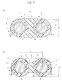
FIG. 2] FIG. 2 is an enlarged cross-sectional view of a connecting portion of the optical fiber ribbon ofFIG. 1 .FIG. 2(A) is a structural example of the connecting portion, andFIG. 2(B) is another structural example of the connecting portion. - [
FIG. 3] FIG. 3 is an enlarged cross-sectional view of a connecting portion of the optical fiber ribbon having another structure ofFIG. 1 .FIG. 3(A) is a structural example of the connecting portion, andFIG. 3(B) is another structural example of the connecting portion. - [
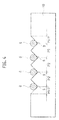
FIG. 4] FIG. 4 is a view showing a state where glass optical fibers in the optical fiber ribbon according to the present embodiment from which covering is removed, are placed in V-shaped grooves of a fusion machine. - [
FIG 5] FIG. 5 is a cross-sectional view of a center tube-type optical fiber cable housing the optical fiber ribbon according to the present embodiment therein. - [
FIG. 6] FIG. 6 is a cross-sectional view of an SZ-slotted optical fiber cable housing the optical fiber ribbon according to the present embodiment therein. - [
FIG. 7] FIG. 7 is a cross-sectional view of a C-slotted optical fiber cable housing the optical fiber ribbon according to the present embodiment therein. - Hereinafter, a specific embodiment of the present invention will be explained in detail with reference to the drawings.
-
FIG. 1 shows an example of an optical fiber ribbon having an intermittent fixing structure according to the present embodiment, andFIG. 2 shows an enlarged cross section of a connecting portion of the optical fiber ribbon ofFIG. 1 . As shown inFIG. 1 , theoptical fiber ribbon 1 according to the present embodiment has a structure in which three or more ofoptical fibers 2 are arranged in parallel, the adjacent twooptical fibers 2 are connected together via connectingportions 3, and the connectingportions 3 are intermittently located in each of a ribbon longitudinal direction (in the X-arrow direction inFIG. 1 ) and a ribbon width direction (in the Y-arrow direction inFIG. 1 ). - As shown in
FIG. 1 , theoptical fiber ribbon 1 is composed of the noptical fibers 2 in total, and the adjacent twooptical fibers 2 of the noptical fibers 2 are intermittently connected together via the connectingportions 3 in each of the ribbon longitudinal direction and the ribbon width direction. The connectingportions 3 connecting the adjacent twooptical fibers 2 together are formed in the ribbon longitudinal direction at a fixed pitch P1, and have a shorter length than unconnected portions each located therebetween. Namely, the length of each connectingportion 3 is shorter than that of each unconnected portion in the ribbon longitudinal direction. - Further, only one connecting
portion 3 is formed in the ribbon width direction to connect the adjacent twooptical fibers 2. The connectingportion 3 is not located on the same line in the ribbon width direction as the other connectingportion 3 connecting other adjacent twooptical fibers 2 but located in the offset position from the other connectingportion 3 in the ribbon longitudinal direction. Therefore, the connectingportions 3 formed in theoptical fiber ribbon 1 are arranged in a zigzag manner as a whole. Note that the arrangement of the connectingportions 3 is not limited to that shown inFIG. 1 and may be other configurations. The arrangement shown inFIG. 1 is merely an example. Here, in addition to the arrangement in which only one connectingportion 3 is provided in the ribbon width direction, two or more connectingportions 3 may be formed in the ribbon width direction in a manner such that at least one unconnected portion is located between the connectingportions 3 - As shown in
FIG. 2(A) , the connectingportion 3 connects the adjacent twooptical fibers 2 together in such a manner as to fill the gap S between the adjacent twooptical fibers 2 with resin (for example, ultraviolet curable resin) and then cure it. Bothsurfaces portion 3 are respectively positioned on the same lines aslines optical fibers 2 when being placed on the horizontal surface. Therefore, the inner half circumferences of theoptical fibers 2 facing the gap S are covered with the resin composing the connectingportion 3, but the outer half circumferences on the opposite side of the gap S are not covered with the resin. - The two
surfaces portion 3 shown inFIG. 2(B) are each formed into a recess having a concave shape curved toward the center of the gap S to separate from thelines optical fibers 2 when being placed on the horizontal surface. InFIG. 2(B) , the amount of the resin composing the connectingportion 3 is smaller than that inFIG. 2(A) , and the resin is locally concentrated in the central portion of the gap S between the twooptical fibers 2. The optical fiber ribbon connected with the connectingportions 3 having such a configuration is more easily bent since the amount of the resin used is smaller than that of the connectingportion 3 shown inFIG. 2(A) , so that the number of the optical fiber ribbons to be housed in a cable further increases. - Each of the
optical fibers 2 includes a bare glassoptical fiber 6 provided in the center thereof, afirst cover layer 7 covering the periphery of the glassoptical fiber 6, and asecond cover layer 8 further covering the periphery of thefirst cover layer 7. The glassoptical fiber 6 has a diameter of 125 µm. Thefirst cover layer 7 is a relatively soft resin layer to absorb lateral pressure applied to the glass. Thesecond cover layer 8 is a relatively hard resin layer to protect against external damage. Thesecond cover layer 8 may be further covered with a colored layer so that the respectiveoptical fibers 2 can be discriminated therebetween. The colored layer is formed as an outermost layer so as to easily differentiate the respectiveoptical fibers 2 visually. - According to the present embodiment, the outer diameter dimension of the optical fibers 2 (the entire diameter including the outermost layer) H is set to smaller than or equal to 220 µm, and the distance L between the centers of the adjacent two
optical fibers 2 is set to 250±30 µm. Theoptical fiber 2 of the present embodiment is a size smaller than theoptical fiber 2 conventionally used which has the outer diameter dimension H of 250 µm. In addition, the distance L between the centers of the adjacent two optical fibers in the optical fiber ribbon conventionally used is 250 µm. The present embodiment sets the distance L to 250 µm with a margin of plus or minus 30 µm. - The connecting
portion 3 shown inFIG. 2(A) has a thickness which is the same as the outer diameter dimension H of theoptical fibers 2. The connectingportion 3 shown inFIG. 2(B) has a thickness which is smaller than the outer diameter dimension H of theoptical fibers 2. - The
optical fiber ribbon 1 has an intermittent fixing structure in which the connectingportions 3 are intermittently provided in each of the ribbon longitudinal direction and the ribbon width direction to connect the adjacent twooptical fibers 2 together, and has a configuration in which theoptical fibers 2 have the outer diameter dimension H of smaller than or equal to 220 µm which is smaller than that of the conventionally-used optical fibers, which contributes to decreasing the diameter of theoptical fibers 2 and easily bending the ribbon. As a result, a larger number of theoptical fiber ribbons 1 can be housed in a cable compared with optical fiber ribbons having a conventional structure so as to increase the packaging density thereof. - Further, since the optical fiber ribbon according to the present embodiment has a configuration in which the
optical fibers 2 have the outer diameter dimension H of smaller than or equal to 220 µm which is smaller than that of the conventionally-used optical fibers, the volume of the optical fibers can be reduced by 20% or greater compared with the optical fibers having a conventional configuration. Accordingly, the entire diameter of the optical fiber ribbon can be decreased so as to further increase the packaging density thereof. - It should be noted that the connecting
portions 3 are not limited to the configurations shown inFIG. 2(A) and FIG. 2(B) in which the connectingportions 3 are formed only in the gap S between the adjacent twooptical fibers 2, but may have the configurations shown inFIG. 3(A) and FIG. 3(B) . The connectingportions 3 shown inFIG. 3 are formed in such a manner as to fill resin into the gap S between the adjacent twooptical fibers 2 and cover the peripheries of theoptical fibers 2 with the resin. The resin thickness T on the outer half circumference of eachoptical fiber 2 covered with the connectingportion 3 is set to smaller than or equal to 15 µm. - The example shown in
FIG. 3 , in which the outer half circumference of eachoptical fiber 2 having the outer diameter dimension of 220 µm is covered with the resin, has no influence on the bending performance of theoptical fiber ribbon 2 since the resin thickness T of the resin covering the outer half circumference is as thin as 15 µm or smaller. Therefore, such a configuration does not prevent the decrease of the packaging density in the cable. - Several types of optical fibers having different outer diameter dimensions were used in which the distance between the centers of adjacent optical fibers varied, so as to manufacture optical fiber ribbons (4-core ribbons). The manufacture of connecting portions and unconnected portions employed the method disclosed in Japanese Unexamined Patent Application Publication No.
2010-033010 2009-082778 08-146239 06-163292 - Next, batch fusion splicing performance was evaluated when one optical fiber ribbon thus obtained was entirely fused with the other optical fiber ribbon. The operation process was as follows. First, the optical fiber ribbon was held with a holder, the
first cover layers 7 and the second cover layers 8 covering the respective optical fibers were removed by use of Hot Jacket Stripper to obtain the bare glassoptical fibers 6, and side surfaces of the bare glassoptical fibers 6 thus obtained were cut with a fiber cutter. Subsequently, the respective glassoptical fibers 6 in the optical fiber ribbon held with the holder were placed on afusion machine 10 having V-shapedgrooves 9 formed at a fixed pitch P2 shown inFIG. 4 . In this state, the evaluation was performed in such a manner as to determine whether the respective glassoptical fibers 6 were placed in the corresponding V-shapedgrooves 9. The case where the glassoptical fibers 6 were placed in the V-shapedgrooves 9 was defined as OK, and the case where the glassoptical fibers 6 deviated from the V-shapedgrooves 9 was defined as NG. - Hot Jacket Stripper used was HJS-02 manufactured by Fujikura Ltd. The fiber cutter used was CT-30 manufactured by Fujikura Ltd. The fusion machine used was FSM-60R also manufactured by Fujikura Ltd. The pitch P between the respective V-shaped
grooves 9 in thefusion machine 10 is 250 µm. The operation under the conditions described above was repeated 10 times and the number of NG was then counted. Table 1 shows the evaluation thereof.[Table 1] Outer Diameter of Optical Fiber (µm) Distance between Centers of Adjacent Optical Fibers (µm) Number of NG in Batch Fusion Splicing Performance 220 300 8 220 280 0 220 250 0 220 230 0 200 280 0 200 250 0 200 220 0 180 300 6 180 280 0 180 250 0 180 220 0 180 200 4 - The results shown in Table 1 revealed that, when the distance L between the centers of the adjacent
optical fibers 2 of theoptical fiber ribbon 1 having an intermittent fixing structure is set to 250±30 µm (220 µm to 280 µm), the glassoptical fibers 6 do not deviate from the V-shapedgrooves 9 so as to be concurrently fused with the corresponding glass optical fibers of the other optical fiber ribbon. The number of NG increased when the optical fiber ribbon did not meet the above-described condition, and the glassoptical fibers 6 could not be placed in the V-shapedgrooves 9 precisely. -
FIG 5 shows an example of a center tube-type optical fiber cable housing the optical fiber cable according to the present embodiment therein. The center tube-typeoptical fiber cable 11 has a configuration in which theoptical fiber cable 1 of the present embodiment is formed into acable core 12 in a manner such that theoptical fibers 2 are rolled in the ribbon width direction and assembled into a bundle as indicated by a dashed and double-dotted line inFIG. 5 , thermoplastic resin is extruded over the periphery of thecable core 12 thus obtained so as to form atube 13 thereon, and thetube 13 is further covered with polyethylene so as to form asheath 14 thereon. -
FIG. 6 shows an example of an SZ-slotted optical fiber cable housing the optical fiber ribbon according to the present embodiment therein. The SZ-slottedoptical fiber cable 15 has a configuration in which a plurality ofslots 18 having a U-shape in cross section are formed on the outer periphery of aslot core 17 including atension member 16 in the center thereof extending in the ribbon longitudinal direction, theoptical fiber ribbon 1 according to the present embodiment is rolled in the ribbon width direction into a bundle and housed in each of theslots 18, the peripheral surface of theslot core 17 including the openings of theslots 18 is covered with apress winding tape 19, and asheath 20 is further formed thereon by extrusion. -
FIG. 7 shows an example of a C-slotted optical fiber cable housing the optical fiber ribbon according to the present embodiment therein. The C-slottedoptical fiber cable 21 has a configuration in which theoptical fiber ribbon 1 according to the present embodiment is rolled in the ribbon width direction into a bundle and housed in aslot groove 24 of aslot core 23 having a C-shape in cross section includingtension members 22 therein, and the entire slot core is covered with asheath 26 via apress winding tape 25 interposed therebetween. - Although the
optical fiber ribbon 1 shown in each ofFIG. 5, FIG. 6 andFIG. 7 according to the present embodiment is rolled in the ribbon width direction into a bundle and housed in the cable, theoptical fiber ribbon 1 according to the present embodiment may be folded in layers in the vertical direction and housed in the cable. Alternatively, a plurality of theoptical fiber ribbons 1 may be stacked on top of one another to have a stacked structure and then housed in the cable. - The
optical fiber cables optical fibers 2 having the reduced outer diameter dimension of smaller than or equal to 220 µm. Therefore, a larger number of theoptical fibers 2 can be housed in the cable, compared with the conventionally-usedoptical fibers 2 having the outer diameter dimension of 250 µm, so as to ensure higher density. Further, theoptical fiber cables optical fiber ribbon 1 having an intermittent fixing structure in any state in a manner such that theoptical fiber ribbon 1 is bent and rolled into a cylindrical shape or folded to be stacked in any direction. - Further, the
optical fiber cables optical fibers 2 from each other so as to improve single-core separation workability at the time of terminal leading to extract theoptical fibers 2 from the terminals of the cable or at the time of connecting operation to connect a connector to the extractedoptical fibers 2, since theoptical fiber cables optical fiber ribbon 1 including the connectingportions 3 intermittently formed in each of the ribbon longitudinal direction and the ribbon width direction to connect the adjacent twooptical fibers 2 together. - The present invention is applicable to the optical fiber ribbon having an intermittent fixing structure to intermittently connect the adjacent optical fibers together via the connecting portions.
Claims (5)
- An optical fiber ribbon comprising three or more of optical fibers arranged in parallel and connecting portions connecting adjacent two optical fibers together, the connecting portions being intermittently provided in each of a ribbon longitudinal direction and a ribbon width direction,
wherein an outer diameter dimension of the optical fibers is set to smaller than or equal to 220 µm, and a distance between centers of the adjacent two optical fibers is set to 250 µm with a margin of plus or minus 30 µm. - The optical fiber ribbon according to claim 1, wherein the connecting portions are each formed in such a manner as to fill resin into a gap between adjacent two optical fibers, and both surfaces of the respective connecting portions are each formed into a recess curved toward a center of the gap to separate from lines each connecting contact points of the optical fibers when being placed on a horizontal surface.
- The optical fiber ribbon according to claim 1, wherein the connecting portions are each formed in such a manner as to fill resin into a gap between adjacent two optical fibers and cover a periphery of the respective optical fibers with the resin, and a resin thickness of the periphery covered with the resin is set to smaller than or equal to 15 µm.
- The optical fiber ribbon according to any one of claims 1 to 3, wherein an outermost layer of the respective optical fibers is colored.
- An optical fiber cable housing the optical fiber ribbon according to any one of claims 1 to 4 therein.
Priority Applications (4)
| Application Number | Priority Date | Filing Date | Title |
|---|---|---|---|
| PL16204376T PL3176620T3 (en) | 2011-10-18 | 2012-10-15 | The method of welding thin optical fibers |
| DK16204376.4T DK3176620T3 (en) | 2011-10-18 | 2012-10-15 | Method for fusion splicing of a band of thin optical fibers |
| PL12842552T PL2770357T3 (en) | 2011-10-18 | 2012-10-15 | Fiber ribbon core wire and fiber optic cable housing fiber ribbon core wire |
| EP16204376.4A EP3176620B1 (en) | 2011-10-18 | 2012-10-15 | Method of fusion splicing a ribbon of thin optical fibres |
Applications Claiming Priority (2)
| Application Number | Priority Date | Filing Date | Title |
|---|---|---|---|
| JP2011229066A JP5564026B2 (en) | 2011-10-18 | 2011-10-18 | Optical fiber tape core and optical fiber cable storing the optical fiber core |
| PCT/JP2012/076590 WO2013058206A1 (en) | 2011-10-18 | 2012-10-15 | Optical fiber tape core wire and optical fiber cable housing optical fiber tape core wire |
Related Child Applications (2)
| Application Number | Title | Priority Date | Filing Date |
|---|---|---|---|
| EP16204376.4A Division EP3176620B1 (en) | 2011-10-18 | 2012-10-15 | Method of fusion splicing a ribbon of thin optical fibres |
| EP16204376.4A Division-Into EP3176620B1 (en) | 2011-10-18 | 2012-10-15 | Method of fusion splicing a ribbon of thin optical fibres |
Publications (3)
| Publication Number | Publication Date |
|---|---|
| EP2770357A1 true EP2770357A1 (en) | 2014-08-27 |
| EP2770357A4 EP2770357A4 (en) | 2015-06-24 |
| EP2770357B1 EP2770357B1 (en) | 2021-01-20 |
Family
ID=48140853
Family Applications (2)
| Application Number | Title | Priority Date | Filing Date |
|---|---|---|---|
| EP12842552.7A Active EP2770357B1 (en) | 2011-10-18 | 2012-10-15 | Optical fiber tape core wire and optical fiber cable housing optical fiber tape core wire |
| EP16204376.4A Active EP3176620B1 (en) | 2011-10-18 | 2012-10-15 | Method of fusion splicing a ribbon of thin optical fibres |
Family Applications After (1)
| Application Number | Title | Priority Date | Filing Date |
|---|---|---|---|
| EP16204376.4A Active EP3176620B1 (en) | 2011-10-18 | 2012-10-15 | Method of fusion splicing a ribbon of thin optical fibres |
Country Status (17)
| Country | Link |
|---|---|
| US (5) | US20160161692A1 (en) |
| EP (2) | EP2770357B1 (en) |
| JP (1) | JP5564026B2 (en) |
| KR (1) | KR20140079824A (en) |
| CN (3) | CN103890628B (en) |
| AU (1) | AU2012327115B2 (en) |
| BR (1) | BR112014009570B1 (en) |
| CA (1) | CA2851090C (en) |
| DK (2) | DK2770357T3 (en) |
| ES (2) | ES2849749T3 (en) |
| HU (2) | HUE057452T2 (en) |
| MY (1) | MY166505A (en) |
| PL (2) | PL3176620T3 (en) |
| PT (2) | PT2770357T (en) |
| RU (1) | RU2589445C2 (en) |
| TW (1) | TWI540355B (en) |
| WO (1) | WO2013058206A1 (en) |
Cited By (18)
| Publication number | Priority date | Publication date | Assignee | Title |
|---|---|---|---|---|
| EP3245546A4 (en) * | 2015-01-15 | 2018-08-22 | Corning Optical Communications LLC | Hybrid optical fiber ribbon and power cable |
| WO2019011417A1 (en) * | 2017-07-11 | 2019-01-17 | Prysmian S.P.A. | An optical fiber ribbon and a method of producing the same |
| US10668706B2 (en) | 2013-11-12 | 2020-06-02 | Baker Hughes, A Ge Company, Llc | Distributed sensing system employing a film adhesive |
| EP3663825A1 (en) * | 2018-12-06 | 2020-06-10 | Sterlite Technologies Limited | Flat drop optical fiber cable |
| EP3548950A4 (en) * | 2016-12-01 | 2020-07-15 | Commscope Technologies LLC | Fiber ribbonizer |
| EP3553578A4 (en) * | 2016-12-06 | 2020-08-12 | Sumitomo Electric Industries, Ltd. | FIBER TAPE CORE WITH SPORADIC JOINT, METHOD OF MANUFACTURING THEREOF, FIBERGLASS CABLE AND FIBERGLASS CORD |
| US10782495B2 (en) | 2018-01-15 | 2020-09-22 | Prysmian S.P.A. | Flexible optical-fiber ribbon |
| US10884213B1 (en) | 2019-11-14 | 2021-01-05 | Prysmian S.P.A. | Optical-fiber ribbon with distorted sinusoidal adhesive pattern and method therefor |
| EP3705923A4 (en) * | 2017-11-02 | 2021-08-11 | Sumitomo Electric Industries, Ltd. | FIBER OPTIC UNIT AND FIBER OPTIC CABLE |
| US11131816B2 (en) | 2017-07-11 | 2021-09-28 | Prysmian S.P.A. | Optical fiber ribbon assembly and a method of producing the same |
| US11256051B2 (en) | 2018-01-15 | 2022-02-22 | Prysmian S.P.A. | Flexible optical-fiber ribbon |
| WO2022108795A1 (en) | 2020-11-19 | 2022-05-27 | Corning Research & Development Corporation | Intermittently bonded ribbon with continuous lengthwise coating |
| US11442238B2 (en) | 2020-12-22 | 2022-09-13 | Prysmian S.P.A. | Optical-fiber ribbon with spaced optical-fiber units |
| US11460652B2 (en) | 2020-12-22 | 2022-10-04 | Prysmian S.P.A. | Optical-fiber ribbon with adhesive-free gaps |
| AU2019472715B2 (en) * | 2019-10-30 | 2022-11-03 | Fujikura Ltd. | Intermittently connected optical fiber ribbon and method for manufacturing intermittently connected optical fiber ribbon |
| US11500171B2 (en) | 2018-01-15 | 2022-11-15 | Prysmian S.P.A. | Optical fiber ribbon and a method and system of producing the same |
| US11650373B2 (en) | 2020-03-24 | 2023-05-16 | Commscope Technologies Llc | Pitch conversion apparatus for use with optical fibers |
| US11860429B2 (en) | 2020-12-22 | 2024-01-02 | Prysmian S.P.A. | Optical-fiber ribbon with spaced optical-fiber units |
Families Citing this family (48)
| Publication number | Priority date | Publication date | Assignee | Title |
|---|---|---|---|---|
| JP5852045B2 (en) * | 2013-05-07 | 2016-02-03 | 株式会社フジクラ | Optical fiber ribbon and optical fiber cable |
| US9389382B2 (en) | 2014-06-03 | 2016-07-12 | Corning Optical Communications LLC | Fiber optic ribbon cable and ribbon |
| JP5802309B2 (en) * | 2014-06-06 | 2015-10-28 | 株式会社フジクラ | Optical fiber tape core and optical fiber cable storing the optical fiber core |
| JP2016061871A (en) | 2014-09-17 | 2016-04-25 | 古河電気工業株式会社 | Optical fiber cable |
| JP6412779B2 (en) * | 2014-11-20 | 2018-10-24 | 株式会社フジクラ | Optical fiber ribbon, optical fiber cable, and optical fiber ribbon manufacturing method |
| JP6329912B2 (en) * | 2015-01-19 | 2018-05-23 | 古河電気工業株式会社 | Optical fiber ribbon, optical fiber cable |
| JP6408389B2 (en) * | 2015-01-26 | 2018-10-17 | 株式会社フジクラ | Optical fiber tape manufacturing method, abnormality detection method and manufacturing system |
| EP3329311A4 (en) | 2015-07-31 | 2019-03-27 | Corning Optical Communications LLC | FIBER OPTIC ROLLER TAPE |
| EP3377931A1 (en) * | 2015-11-18 | 2018-09-26 | Corning Optical Communications LLC | Optical fiber cable with internal periodic coupling structure |
| JP6106253B1 (en) * | 2015-12-04 | 2017-03-29 | 株式会社フジクラ | OPTICAL FIBER TAPE, OPTICAL FIBER TAPE MANUFACTURING METHOD, AND ULTRAVIOLET-CURABLE RESIN COMPOSITION USED FOR FORMING INTERCONNECTION OF INTERNAL FIXED OPTICAL FIBER TAPE |
| US10094995B2 (en) * | 2016-02-16 | 2018-10-09 | Ofs Fitel, Llc | Rollable ribbons in loose-tube cable structures |
| EP3422062B1 (en) | 2016-02-23 | 2025-09-03 | Sumitomo Electric Industries, Ltd. | Intermittent connection type optical fiber ribbon, manufacturing method for intermittent connection type optical fiber ribbon, optical fiber cable and optical fiber cord |
| JP6586925B2 (en) | 2016-06-13 | 2019-10-09 | 住友電気工業株式会社 | Fiber optic cable |
| CA3038637C (en) | 2016-09-30 | 2021-05-04 | Fujikura Ltd. | Optical fiber ribbon, optical fiber cable, and method of manufacturing optical fiber ribbon |
| EP3521883A4 (en) | 2016-09-30 | 2020-05-13 | Fujikura Ltd. | COLORED FIBER OPTIC CORE, FIBER OPTIC CABLE, AND METHOD OF MANUFACTURING COLORED CORE OPTICAL FIBERS |
| EP3561564B1 (en) * | 2016-12-20 | 2025-07-16 | Furukawa Electric Co., Ltd. | Method for manufacturing optical fiber intermittent tape core and optical fiber intermittent tape core |
| JP2018106098A (en) * | 2016-12-28 | 2018-07-05 | 株式会社フジクラ | Method of manufacturing intermittently fixed optical fiber ribbon |
| CN110268296A (en) | 2017-01-25 | 2019-09-20 | Afl电信有限责任公司 | Reduced Diameter Reinforced Fiber Optic Distribution Cables |
| WO2019021998A1 (en) | 2017-07-24 | 2019-01-31 | 住友電気工業株式会社 | Optical fiber ribbon and optical fiber cable |
| EP3665521B1 (en) | 2017-08-08 | 2023-11-08 | Corning Research & Development Corporation | Rollable optical fiber ribbon with low attenuation, large mode field diameter optical fiber and cable |
| US20190219783A1 (en) * | 2018-01-12 | 2019-07-18 | Ofs Fitel, Llc | Multi-fiber unit tube optical fiber microcable incorporating rollable optical fibers ribbons |
| CN111630426B (en) | 2018-01-18 | 2022-05-06 | 住友电气工业株式会社 | Manufacturing method and manufacturing device of optical fiber ribbon |
| US11585995B2 (en) * | 2018-11-05 | 2023-02-21 | Sterlite Technologies Limited | Matrix material for rollable optical fiber ribbons |
| EP3884326B1 (en) * | 2018-11-20 | 2025-01-01 | Ofs Fitel Llc | Optical fiber cable having rollable ribbons and central strength member |
| US11150424B2 (en) * | 2018-12-06 | 2021-10-19 | Sterlite Technologies Limited | Rollable optical fiber ribbon |
| US11415769B2 (en) | 2019-02-06 | 2022-08-16 | Sumitomo Electric Industries, Ltd. | Intermittent connection-type optical fiber tape core wire, optical fiber cable, and method for manufacturing intermittent connection-type optical fiber tape core wire |
| JP6855519B2 (en) | 2019-02-08 | 2021-04-07 | 株式会社フジクラ | Optical fiber unit and processing method of optical fiber unit |
| JPWO2020189772A1 (en) | 2019-03-20 | 2020-09-24 | ||
| US11209605B2 (en) * | 2019-04-12 | 2021-12-28 | Sumitomo Electric Industries, Ltd. | Optical fiber ribbon, die, and method of manufacturing optical fiber ribbon |
| WO2020241696A1 (en) | 2019-05-28 | 2020-12-03 | 住友電気工業株式会社 | Optical fiber tape core wire, optical fiber cable, and method of manufacturing optical fiber tape core wire |
| JP2020204687A (en) * | 2019-06-17 | 2020-12-24 | 住友電気工業株式会社 | Optical fiber ribbon, optical fiber cable, and method for manufacturing optical fiber ribbon |
| CN110148488A (en) * | 2019-05-31 | 2019-08-20 | 江苏鸿翔电缆有限公司 | A kind of novel optical fiber complex controll cable |
| US11886026B2 (en) | 2019-09-05 | 2024-01-30 | Sumitomo Electric Industries, Ltd. | Optical fiber ribbon, optical fiber cable, and connector-equipped optical fiber cord |
| JP7157026B2 (en) | 2019-09-12 | 2022-10-19 | 株式会社フジクラ | Optical fiber alignment method, optical fiber fusion splicing method, method for manufacturing optical fiber tape with connector, and intermittent connection type optical fiber tape |
| US11953744B2 (en) | 2020-03-09 | 2024-04-09 | Sumitomo Electric Industries, Ltd. | Optical fiber ribbon and optical fiber cable |
| US11828996B2 (en) | 2020-03-09 | 2023-11-28 | Sumitomo Electric Industries, Ltd. | Optical fiber ribbon and optical fiber cable |
| EP4139730A4 (en) | 2020-04-24 | 2024-06-19 | CommScope Technologies LLC | Fiber routing systems and methods |
| EP4191310B1 (en) | 2020-07-29 | 2025-11-12 | Sumitomo Electric Industries, Ltd. | Method for manufacturing intermittent connection-type optical fiber tape core wire and intermittent connection-type optical fiber tape core wire |
| CN116324556A (en) | 2020-08-31 | 2023-06-23 | 康宁研究与开发公司 | Intermittently bonded belt having intermittent bonds produced with a wet-on-wet process |
| JPWO2022065485A1 (en) * | 2020-09-28 | 2022-03-31 | ||
| WO2022086700A1 (en) | 2020-10-19 | 2022-04-28 | Corning Research & Development Corporation | Ribbon with non-overlapping intermittent bonds between optical fiber subunits |
| JP7816160B2 (en) * | 2020-10-19 | 2026-02-18 | 住友電気工業株式会社 | Optical fiber ribbon |
| CN113359230B (en) * | 2021-05-18 | 2022-04-29 | 烽火通信科技股份有限公司 | A flexible optical fiber ribbon and optical fiber cable |
| CA3226013A1 (en) * | 2021-07-21 | 2023-01-26 | Ls Cable & System Ltd. | Optical fiber ribbon |
| WO2023081039A1 (en) * | 2021-11-03 | 2023-05-11 | Corning Research & Development Corporation | Optical fiber ribbon configured to maintain orientation of polarization-maintaining and multicore optical fibers |
| US20230168441A1 (en) * | 2021-11-30 | 2023-06-01 | Corning Research & Development Corporation | Unjacketed fiber optic cable assembly, and cable assembly including connector with travel limited ferrule |
| KR102800069B1 (en) * | 2022-04-07 | 2025-04-23 | 후루카와 덴키 고교 가부시키가이샤 | Fiber Optic Tape Core |
| CN121232355A (en) * | 2025-12-01 | 2025-12-30 | 江苏亨通光电股份有限公司 | A rollable optical cable and its manufacturing method |
Family Cites Families (62)
| Publication number | Priority date | Publication date | Assignee | Title |
|---|---|---|---|---|
| JPS55155314A (en) * | 1979-05-21 | 1980-12-03 | Nippon Telegr & Teleph Corp <Ntt> | Connecting method of optical fiber and its connector |
| US4547040A (en) * | 1983-06-21 | 1985-10-15 | Mitsubishi Rayon Co., Ltd. | Optical fiber assembly and process for preparing same |
| US4662713A (en) * | 1984-08-13 | 1987-05-05 | American Telephone And Telegraph Company At&T Bell Laboratories | Optical fiber connector and articles connected therewith |
| US4730198A (en) * | 1984-11-26 | 1988-03-08 | American Telephone And Telegraph Company, At&T Bell Laboratories | Aligning arrays of optoelectronic devices to arrays of optical fibers |
| EP0271721B1 (en) * | 1986-11-15 | 1993-08-04 | Sumitomo Electric Industries Limited | Optical connector and process for producing the same |
| US4869570A (en) * | 1987-02-21 | 1989-09-26 | Nippon Telegraph And Telephone Corporation | Fiber coupler and method and apparatus for manufacturing the same |
| US4789214A (en) * | 1987-09-21 | 1988-12-06 | Tacan Corporation | Micro-optical building block system and method of making same |
| JP2573633B2 (en) * | 1987-11-26 | 1997-01-22 | 住友電気工業株式会社 | Tape-type optical fiber manufacturing equipment |
| JPH0617923B2 (en) * | 1987-12-16 | 1994-03-09 | 株式会社フジクラ | Optical fiber heating measurement method |
| JPH0256510A (en) * | 1988-08-23 | 1990-02-26 | Sumitomo Electric Ind Ltd | Production of tape type coated optical fibers |
| JP2533014Y2 (en) * | 1989-02-10 | 1997-04-16 | 日本電気硝子 株式会社 | Permanent splicer for ribbon-shaped multi-core optical fiber |
| JPH04145403A (en) * | 1990-10-05 | 1992-05-19 | Seiko Giken:Kk | Branching and joining device for multiple optical fiber ribbon tape and its production |
| JPH04268522A (en) * | 1991-02-22 | 1992-09-24 | Fujikura Ltd | Production of coated tape optical fiber |
| JP3058203B2 (en) | 1991-07-11 | 2000-07-04 | 株式会社フジクラ | Optical cable |
| JP2695582B2 (en) * | 1992-08-03 | 1997-12-24 | 住友電気工業株式会社 | Method and device for aligning optical fiber on V groove |
| JP2888711B2 (en) | 1992-11-19 | 1999-05-10 | 三菱電機株式会社 | Line production flow of large electrical equipment |
| US5627930A (en) * | 1993-04-19 | 1997-05-06 | Sumitomo Electric Industries, Ltd. | Arrayed optical fiber coupler and method of manufacturing the same |
| DE69408752T2 (en) * | 1993-08-26 | 1998-07-02 | Fujikura Ltd | Adjustment device for aligning optical fibers |
| JPH08146239A (en) | 1994-06-23 | 1996-06-07 | Fujikura Ltd | Optical fiber tape manufacturing apparatus and manufacturing method thereof |
| JP2976819B2 (en) * | 1994-08-25 | 1999-11-10 | 日立電線株式会社 | How to connect optical fiber ribbon |
| JPH08220397A (en) * | 1995-02-13 | 1996-08-30 | Fujikura Ltd | Composite optical fiber tape with tape numbering by coloring the strands |
| US5637900A (en) * | 1995-04-06 | 1997-06-10 | Industrial Technology Research Institute | Latchup-free fully-protected CMOS on-chip ESD protection circuit |
| FR2736441B1 (en) * | 1995-07-04 | 1997-09-26 | Noane Georges Le | DEVICE AND METHOD FOR TRACKING AND CONNECTING MULTI-CORE FIBERS |
| SE510365C2 (en) | 1996-05-03 | 1999-05-17 | Ericsson Telefon Ab L M | Process for producing an opto-mechanical device and such device |
| JP4390160B2 (en) * | 1998-06-26 | 2009-12-24 | 住友電気工業株式会社 | Batch coating die apparatus for manufacturing a split type optical fiber ribbon and manufacturing method |
| JP2000193844A (en) * | 1998-10-20 | 2000-07-14 | Sumitomo Metal Mining Co Ltd | Manufacturing method of optical fiber array |
| DE60003736T2 (en) * | 1999-03-17 | 2004-06-03 | Hamamatsu Photonics K.K., Hamamatsu | Laser device and associated amplifier for optical signals |
| US6421493B1 (en) * | 2000-03-24 | 2002-07-16 | Fitel Usa Corp. | Apparatus and method for assembling and aligning a plurality of optical fibers |
| EP1174744A1 (en) * | 2000-07-21 | 2002-01-23 | Corning Incorporated | Method and apparatus for splicing optical fibers |
| US6584257B1 (en) * | 2000-12-27 | 2003-06-24 | Corning Cable Systems, Llc | Fiber optic assembly and method of making same |
| JP2002328277A (en) * | 2001-04-26 | 2002-11-15 | Fujikura Ltd | Optical cable |
| JP2003232972A (en) * | 2002-02-07 | 2003-08-22 | Sumitomo Electric Ind Ltd | Optical fiber ribbon |
| CA2475970A1 (en) * | 2002-05-28 | 2003-12-04 | Sumitomo Electric Industries, Ltd. | Optical fiber tape core |
| JP2004126563A (en) * | 2002-09-02 | 2004-04-22 | Seiko Instruments Inc | Lens-integrated optical fiber and method of manufacturing the same |
| AU2003276713A1 (en) * | 2002-11-06 | 2004-06-07 | Sumitomo Electric Industries, Ltd. | Optical fiber ribbon and optical fiber cable using the same |
| JP2005017662A (en) * | 2003-06-26 | 2005-01-20 | Sumitomo Electric Ind Ltd | Optical fiber fusion splicing device and fusion splicing method |
| JP3951133B2 (en) * | 2003-07-23 | 2007-08-01 | 住友電気工業株式会社 | Fiber optic cable |
| US6942397B2 (en) * | 2003-07-25 | 2005-09-13 | Xponent Photonics Inc | Packaging for a fiber-coupled optical device |
| JP4055000B2 (en) * | 2003-08-11 | 2008-03-05 | 住友電気工業株式会社 | Optical fiber cable, optical fiber cable manufacturing method, and optical fiber cable manufacturing apparatus |
| JP2007507007A (en) * | 2003-09-25 | 2007-03-22 | コーニング インコーポレイテッド | Fiber lens with multimode pigtail |
| US6973245B2 (en) * | 2003-12-30 | 2005-12-06 | Furukawa Electric North America | Optical fiber cables |
| JP2005227721A (en) * | 2004-02-16 | 2005-08-25 | Sumitomo Electric Ind Ltd | Optical connector, optical module, and method of manufacturing optical connector |
| US20080056653A1 (en) * | 2004-04-14 | 2008-03-06 | Takahiro Sato | Optical Fiber Tape Unit and Optical Fiber Cable |
| KR100624052B1 (en) * | 2005-06-22 | 2006-09-15 | 주식회사 나노포토닉스 | An optical component comprising a lens having at least one aspherical refractive surface |
| KR20080022553A (en) * | 2005-06-24 | 2008-03-11 | 쓰리엠 이노베이티브 프로퍼티즈 컴파니 | Optical device and method with cantilevered fiber array |
| JP2007058206A (en) | 2005-07-28 | 2007-03-08 | Furukawa Electric Co Ltd:The | Optical fiber ribbon and optical fiber tape unit |
| JP4143651B2 (en) * | 2006-04-04 | 2008-09-03 | 株式会社フジクラ | OPTICAL FIBER TAPE CORE AND OPTICAL FIBER CABLE CONTAINING THE OPTICAL FIBER TAPE |
| JP2009082778A (en) | 2007-09-28 | 2009-04-23 | Tomoaki Ito | Recycling equipment |
| JP2009163045A (en) * | 2008-01-08 | 2009-07-23 | Fujikura Ltd | Optical fiber ribbon and its dividing method |
| JP4966920B2 (en) * | 2008-06-20 | 2012-07-04 | 株式会社フジクラ | Method and apparatus for manufacturing optical fiber ribbon |
| JP5149230B2 (en) * | 2008-06-23 | 2013-02-20 | 株式会社フジクラ | Manufacturing method and manufacturing apparatus for optical fiber ribbon |
| CN102057309B (en) * | 2008-06-30 | 2014-04-16 | 日本电信电话株式会社 | Fiber optic cables and ribbons |
| JP5442234B2 (en) * | 2008-10-24 | 2014-03-12 | 株式会社半導体エネルギー研究所 | Semiconductor device and display device |
| TWI585955B (en) * | 2008-11-28 | 2017-06-01 | 半導體能源研究所股份有限公司 | Light sensor and display device |
| JP2010224478A (en) * | 2009-03-25 | 2010-10-07 | Hitachi Cable Ltd | Tape optical fiber |
| JP2010237292A (en) * | 2009-03-30 | 2010-10-21 | Fujikura Ltd | Manufacturing method and manufacturing apparatus for optical fiber ribbon |
| TWI405781B (en) | 2009-07-08 | 2013-08-21 | Tsrc Corp | Coupled polymers and manufacturing methods thereof |
| JP2011100115A (en) | 2009-10-06 | 2011-05-19 | Fujikura Ltd | Optical fiber cable |
| JP2011229066A (en) | 2010-04-22 | 2011-11-10 | Panasonic Electric Works Co Ltd | Imaging apparatus |
| CN102590933B (en) * | 2012-01-10 | 2015-07-01 | 长飞光纤光缆股份有限公司 | Bending insensitive single-mode optical fiber |
| US10175421B2 (en) * | 2013-03-14 | 2019-01-08 | Vascular Imaging Corporation | Optical fiber ribbon imaging guidewire and methods |
| WO2015099764A1 (en) * | 2013-12-27 | 2015-07-02 | Intel Corporation | Asymmetric optical waveguide grating resonators & dbr lasers |
-
2011
- 2011-10-18 JP JP2011229066A patent/JP5564026B2/en active Active
-
2012
- 2012-10-15 WO PCT/JP2012/076590 patent/WO2013058206A1/en not_active Ceased
- 2012-10-15 CA CA2851090A patent/CA2851090C/en active Active
- 2012-10-15 CN CN201280051112.9A patent/CN103890628B/en active Active
- 2012-10-15 HU HUE16204376A patent/HUE057452T2/en unknown
- 2012-10-15 CN CN201611199291.7A patent/CN106932870B/en active Active
- 2012-10-15 KR KR1020147012805A patent/KR20140079824A/en not_active Ceased
- 2012-10-15 PT PT128425527T patent/PT2770357T/en unknown
- 2012-10-15 HU HUE12842552A patent/HUE053884T2/en unknown
- 2012-10-15 EP EP12842552.7A patent/EP2770357B1/en active Active
- 2012-10-15 AU AU2012327115A patent/AU2012327115B2/en active Active
- 2012-10-15 ES ES12842552T patent/ES2849749T3/en active Active
- 2012-10-15 DK DK12842552.7T patent/DK2770357T3/en active
- 2012-10-15 PL PL16204376T patent/PL3176620T3/en unknown
- 2012-10-15 CN CN201611198605.1A patent/CN106873101A/en active Pending
- 2012-10-15 DK DK16204376.4T patent/DK3176620T3/en active
- 2012-10-15 RU RU2014119931/28A patent/RU2589445C2/en active
- 2012-10-15 ES ES16204376T patent/ES2897006T3/en active Active
- 2012-10-15 BR BR112014009570-1A patent/BR112014009570B1/en active IP Right Grant
- 2012-10-15 MY MYPI2014001057A patent/MY166505A/en unknown
- 2012-10-15 PL PL12842552T patent/PL2770357T3/en unknown
- 2012-10-15 PT PT162043764T patent/PT3176620T/en unknown
- 2012-10-15 EP EP16204376.4A patent/EP3176620B1/en active Active
- 2012-10-18 TW TW101138424A patent/TWI540355B/en active
-
2014
- 2014-04-11 US US14/251,233 patent/US20160161692A1/en not_active Abandoned
-
2017
- 2017-01-09 US US15/401,374 patent/US9995896B2/en active Active
- 2017-01-09 US US15/401,336 patent/US20170115461A1/en not_active Abandoned
-
2020
- 2020-03-20 US US16/825,336 patent/US11422325B2/en active Active
-
2022
- 2022-06-15 US US17/841,262 patent/US11892694B2/en active Active
Cited By (26)
| Publication number | Priority date | Publication date | Assignee | Title |
|---|---|---|---|---|
| US10668706B2 (en) | 2013-11-12 | 2020-06-02 | Baker Hughes, A Ge Company, Llc | Distributed sensing system employing a film adhesive |
| EP3245546A4 (en) * | 2015-01-15 | 2018-08-22 | Corning Optical Communications LLC | Hybrid optical fiber ribbon and power cable |
| EP3548950A4 (en) * | 2016-12-01 | 2020-07-15 | Commscope Technologies LLC | Fiber ribbonizer |
| EP3553578A4 (en) * | 2016-12-06 | 2020-08-12 | Sumitomo Electric Industries, Ltd. | FIBER TAPE CORE WITH SPORADIC JOINT, METHOD OF MANUFACTURING THEREOF, FIBERGLASS CABLE AND FIBERGLASS CORD |
| US11131816B2 (en) | 2017-07-11 | 2021-09-28 | Prysmian S.P.A. | Optical fiber ribbon assembly and a method of producing the same |
| WO2019011417A1 (en) * | 2017-07-11 | 2019-01-17 | Prysmian S.P.A. | An optical fiber ribbon and a method of producing the same |
| AU2017423261B2 (en) * | 2017-07-11 | 2023-07-20 | Prysmian S.P.A. | An optical fiber ribbon and a method of producing the same |
| US10983297B2 (en) | 2017-07-11 | 2021-04-20 | Prysmian S.P.A. | Optical fiber ribbon and a method of producing the same |
| US11209606B2 (en) | 2017-11-02 | 2021-12-28 | Sumitomo Electric Industries, Ltd. | Optical fiber unit and optical fiber cable |
| EP3705923A4 (en) * | 2017-11-02 | 2021-08-11 | Sumitomo Electric Industries, Ltd. | FIBER OPTIC UNIT AND FIBER OPTIC CABLE |
| US10782495B2 (en) | 2018-01-15 | 2020-09-22 | Prysmian S.P.A. | Flexible optical-fiber ribbon |
| US11169342B2 (en) | 2018-01-15 | 2021-11-09 | Prysmian S.P.A. | Flexible optical-fiber ribbon |
| US11256051B2 (en) | 2018-01-15 | 2022-02-22 | Prysmian S.P.A. | Flexible optical-fiber ribbon |
| US12001070B2 (en) | 2018-01-15 | 2024-06-04 | Prysmian S.P.A. | Flexible optical-fiber ribbon |
| US11656417B2 (en) | 2018-01-15 | 2023-05-23 | Prysmian S.P.A. | Flexible optical-fiber ribbon |
| US11500171B2 (en) | 2018-01-15 | 2022-11-15 | Prysmian S.P.A. | Optical fiber ribbon and a method and system of producing the same |
| EP3663825A1 (en) * | 2018-12-06 | 2020-06-10 | Sterlite Technologies Limited | Flat drop optical fiber cable |
| AU2019472715B2 (en) * | 2019-10-30 | 2022-11-03 | Fujikura Ltd. | Intermittently connected optical fiber ribbon and method for manufacturing intermittently connected optical fiber ribbon |
| US11536922B2 (en) | 2019-10-30 | 2022-12-27 | Fujikura Ltd. | Intermittently connected optical fiber ribbon and method for manufacturing intermittently connected optical fiber ribbon |
| US10884213B1 (en) | 2019-11-14 | 2021-01-05 | Prysmian S.P.A. | Optical-fiber ribbon with distorted sinusoidal adhesive pattern and method therefor |
| US11650373B2 (en) | 2020-03-24 | 2023-05-16 | Commscope Technologies Llc | Pitch conversion apparatus for use with optical fibers |
| WO2022108795A1 (en) | 2020-11-19 | 2022-05-27 | Corning Research & Development Corporation | Intermittently bonded ribbon with continuous lengthwise coating |
| EP4248250A4 (en) * | 2020-11-19 | 2024-10-30 | Corning Research & Development Corporation | INTERMITTENT BONDED TAPE WITH CONTINUOUS LONGITUDINAL COATING |
| US11460652B2 (en) | 2020-12-22 | 2022-10-04 | Prysmian S.P.A. | Optical-fiber ribbon with adhesive-free gaps |
| US11442238B2 (en) | 2020-12-22 | 2022-09-13 | Prysmian S.P.A. | Optical-fiber ribbon with spaced optical-fiber units |
| US11860429B2 (en) | 2020-12-22 | 2024-01-02 | Prysmian S.P.A. | Optical-fiber ribbon with spaced optical-fiber units |
Also Published As
Similar Documents
| Publication | Publication Date | Title |
|---|---|---|
| US11422325B2 (en) | Optical fiber ribbon and optical fiber cable housing optical fiber ribbon | |
| JP5802309B2 (en) | Optical fiber tape core and optical fiber cable storing the optical fiber core | |
| JP5852045B2 (en) | Optical fiber ribbon and optical fiber cable | |
| US9057845B2 (en) | Multi-ferrule optical fiber cable assembly | |
| EP3404462B1 (en) | Intermittently joined optical fiber ribbon and optical cable | |
| US5574817A (en) | Fiber optic ribbon cable assembly and method of manufacturing same | |
| EP3660566B1 (en) | Optical fiber ribbon and optical fiber cable | |
| US20190317289A1 (en) | Method for manufacturing intermittently-fixed optical fiber ribbon | |
| US20200026016A1 (en) | High density, low bend loss optical fiber ribbon cable | |
| JP5947967B2 (en) | Optical fiber ribbon and optical fiber cable | |
| JP2022014544A (en) | Optical fiber ribbon and optical fiber cable | |
| NZ623457B2 (en) | Optical fiber ribbon and optical fiber cable housing optical fiber ribbon | |
| EP4235245B1 (en) | Pre-terminated optical cable | |
| WO2017165169A9 (en) | Assembly for distributing trunk cable to furcated cable |
Legal Events
| Date | Code | Title | Description |
|---|---|---|---|
| PUAI | Public reference made under article 153(3) epc to a published international application that has entered the european phase |
Free format text: ORIGINAL CODE: 0009012 |
|
| 17P | Request for examination filed |
Effective date: 20140507 |
|
| AK | Designated contracting states |
Kind code of ref document: A1 Designated state(s): AL AT BE BG CH CY CZ DE DK EE ES FI FR GB GR HR HU IE IS IT LI LT LU LV MC MK MT NL NO PL PT RO RS SE SI SK SM TR |
|
| DAX | Request for extension of the european patent (deleted) | ||
| RA4 | Supplementary search report drawn up and despatched (corrected) |
Effective date: 20150527 |
|
| RIC1 | Information provided on ipc code assigned before grant |
Ipc: G02B 6/44 20060101AFI20150520BHEP |
|
| STAA | Information on the status of an ep patent application or granted ep patent |
Free format text: STATUS: EXAMINATION IS IN PROGRESS |
|
| 17Q | First examination report despatched |
Effective date: 20170509 |
|
| GRAP | Despatch of communication of intention to grant a patent |
Free format text: ORIGINAL CODE: EPIDOSNIGR1 |
|
| STAA | Information on the status of an ep patent application or granted ep patent |
Free format text: STATUS: GRANT OF PATENT IS INTENDED |
|
| INTG | Intention to grant announced |
Effective date: 20200820 |
|
| GRAS | Grant fee paid |
Free format text: ORIGINAL CODE: EPIDOSNIGR3 |
|
| GRAA | (expected) grant |
Free format text: ORIGINAL CODE: 0009210 |
|
| STAA | Information on the status of an ep patent application or granted ep patent |
Free format text: STATUS: THE PATENT HAS BEEN GRANTED |
|
| AK | Designated contracting states |
Kind code of ref document: B1 Designated state(s): AL AT BE BG CH CY CZ DE DK EE ES FI FR GB GR HR HU IE IS IT LI LT LU LV MC MK MT NL NO PL PT RO RS SE SI SK SM TR |
|
| REG | Reference to a national code |
Ref country code: GB Ref legal event code: FG4D |
|
| REG | Reference to a national code |
Ref country code: CH Ref legal event code: EP |
|
| REG | Reference to a national code |
Ref country code: DE Ref legal event code: R096 Ref document number: 602012074246 Country of ref document: DE |
|
| REG | Reference to a national code |
Ref country code: AT Ref legal event code: REF Ref document number: 1356906 Country of ref document: AT Kind code of ref document: T Effective date: 20210215 |
|
| REG | Reference to a national code |
Ref country code: IE Ref legal event code: FG4D |
|
| REG | Reference to a national code |
Ref country code: PT Ref legal event code: SC4A Ref document number: 2770357 Country of ref document: PT Date of ref document: 20210304 Kind code of ref document: T Free format text: AVAILABILITY OF NATIONAL TRANSLATION Effective date: 20210225 |
|
| REG | Reference to a national code |
Ref country code: SE Ref legal event code: TRGR |
|
| REG | Reference to a national code |
Ref country code: NL Ref legal event code: FP |
|
| REG | Reference to a national code |
Ref country code: DK Ref legal event code: T3 Effective date: 20210408 |
|
| REG | Reference to a national code |
Ref country code: LT Ref legal event code: MG9D |
|
| REG | Reference to a national code |
Ref country code: AT Ref legal event code: MK05 Ref document number: 1356906 Country of ref document: AT Kind code of ref document: T Effective date: 20210120 |
|
| REG | Reference to a national code |
Ref country code: HU Ref legal event code: AG4A Ref document number: E053884 Country of ref document: HU |
|
| PG25 | Lapsed in a contracting state [announced via postgrant information from national office to epo] |
Ref country code: LT Free format text: LAPSE BECAUSE OF FAILURE TO SUBMIT A TRANSLATION OF THE DESCRIPTION OR TO PAY THE FEE WITHIN THE PRESCRIBED TIME-LIMIT Effective date: 20210120 Ref country code: GR Free format text: LAPSE BECAUSE OF FAILURE TO SUBMIT A TRANSLATION OF THE DESCRIPTION OR TO PAY THE FEE WITHIN THE PRESCRIBED TIME-LIMIT Effective date: 20210421 Ref country code: FI Free format text: LAPSE BECAUSE OF FAILURE TO SUBMIT A TRANSLATION OF THE DESCRIPTION OR TO PAY THE FEE WITHIN THE PRESCRIBED TIME-LIMIT Effective date: 20210120 Ref country code: HR Free format text: LAPSE BECAUSE OF FAILURE TO SUBMIT A TRANSLATION OF THE DESCRIPTION OR TO PAY THE FEE WITHIN THE PRESCRIBED TIME-LIMIT Effective date: 20210120 Ref country code: BG Free format text: LAPSE BECAUSE OF FAILURE TO SUBMIT A TRANSLATION OF THE DESCRIPTION OR TO PAY THE FEE WITHIN THE PRESCRIBED TIME-LIMIT Effective date: 20210420 Ref country code: NO Free format text: LAPSE BECAUSE OF FAILURE TO SUBMIT A TRANSLATION OF THE DESCRIPTION OR TO PAY THE FEE WITHIN THE PRESCRIBED TIME-LIMIT Effective date: 20210420 |
|
| REG | Reference to a national code |
Ref country code: ES Ref legal event code: FG2A Ref document number: 2849749 Country of ref document: ES Kind code of ref document: T3 Effective date: 20210820 |
|
| PG25 | Lapsed in a contracting state [announced via postgrant information from national office to epo] |
Ref country code: AT Free format text: LAPSE BECAUSE OF FAILURE TO SUBMIT A TRANSLATION OF THE DESCRIPTION OR TO PAY THE FEE WITHIN THE PRESCRIBED TIME-LIMIT Effective date: 20210120 Ref country code: RS Free format text: LAPSE BECAUSE OF FAILURE TO SUBMIT A TRANSLATION OF THE DESCRIPTION OR TO PAY THE FEE WITHIN THE PRESCRIBED TIME-LIMIT Effective date: 20210120 Ref country code: LV Free format text: LAPSE BECAUSE OF FAILURE TO SUBMIT A TRANSLATION OF THE DESCRIPTION OR TO PAY THE FEE WITHIN THE PRESCRIBED TIME-LIMIT Effective date: 20210120 |
|
| PG25 | Lapsed in a contracting state [announced via postgrant information from national office to epo] |
Ref country code: IS Free format text: LAPSE BECAUSE OF FAILURE TO SUBMIT A TRANSLATION OF THE DESCRIPTION OR TO PAY THE FEE WITHIN THE PRESCRIBED TIME-LIMIT Effective date: 20210520 |
|
| REG | Reference to a national code |
Ref country code: DE Ref legal event code: R097 Ref document number: 602012074246 Country of ref document: DE |
|
| PG25 | Lapsed in a contracting state [announced via postgrant information from national office to epo] |
Ref country code: CZ Free format text: LAPSE BECAUSE OF FAILURE TO SUBMIT A TRANSLATION OF THE DESCRIPTION OR TO PAY THE FEE WITHIN THE PRESCRIBED TIME-LIMIT Effective date: 20210120 Ref country code: EE Free format text: LAPSE BECAUSE OF FAILURE TO SUBMIT A TRANSLATION OF THE DESCRIPTION OR TO PAY THE FEE WITHIN THE PRESCRIBED TIME-LIMIT Effective date: 20210120 Ref country code: SM Free format text: LAPSE BECAUSE OF FAILURE TO SUBMIT A TRANSLATION OF THE DESCRIPTION OR TO PAY THE FEE WITHIN THE PRESCRIBED TIME-LIMIT Effective date: 20210120 |
|
| PLBE | No opposition filed within time limit |
Free format text: ORIGINAL CODE: 0009261 |
|
| STAA | Information on the status of an ep patent application or granted ep patent |
Free format text: STATUS: NO OPPOSITION FILED WITHIN TIME LIMIT |
|
| PG25 | Lapsed in a contracting state [announced via postgrant information from national office to epo] |
Ref country code: SK Free format text: LAPSE BECAUSE OF FAILURE TO SUBMIT A TRANSLATION OF THE DESCRIPTION OR TO PAY THE FEE WITHIN THE PRESCRIBED TIME-LIMIT Effective date: 20210120 Ref country code: RO Free format text: LAPSE BECAUSE OF FAILURE TO SUBMIT A TRANSLATION OF THE DESCRIPTION OR TO PAY THE FEE WITHIN THE PRESCRIBED TIME-LIMIT Effective date: 20210120 |
|
| 26N | No opposition filed |
Effective date: 20211021 |
|
| PG25 | Lapsed in a contracting state [announced via postgrant information from national office to epo] |
Ref country code: AL Free format text: LAPSE BECAUSE OF FAILURE TO SUBMIT A TRANSLATION OF THE DESCRIPTION OR TO PAY THE FEE WITHIN THE PRESCRIBED TIME-LIMIT Effective date: 20210120 |
|
| PG25 | Lapsed in a contracting state [announced via postgrant information from national office to epo] |
Ref country code: SI Free format text: LAPSE BECAUSE OF FAILURE TO SUBMIT A TRANSLATION OF THE DESCRIPTION OR TO PAY THE FEE WITHIN THE PRESCRIBED TIME-LIMIT Effective date: 20210120 |
|
| PG25 | Lapsed in a contracting state [announced via postgrant information from national office to epo] |
Ref country code: IS Free format text: LAPSE BECAUSE OF FAILURE TO SUBMIT A TRANSLATION OF THE DESCRIPTION OR TO PAY THE FEE WITHIN THE PRESCRIBED TIME-LIMIT Effective date: 20210520 |
|
| REG | Reference to a national code |
Ref country code: CH Ref legal event code: PL |
|
| PG25 | Lapsed in a contracting state [announced via postgrant information from national office to epo] |
Ref country code: MC Free format text: LAPSE BECAUSE OF FAILURE TO SUBMIT A TRANSLATION OF THE DESCRIPTION OR TO PAY THE FEE WITHIN THE PRESCRIBED TIME-LIMIT Effective date: 20210120 |
|
| PG25 | Lapsed in a contracting state [announced via postgrant information from national office to epo] |
Ref country code: LU Free format text: LAPSE BECAUSE OF NON-PAYMENT OF DUE FEES Effective date: 20211015 |
|
| PG25 | Lapsed in a contracting state [announced via postgrant information from national office to epo] |
Ref country code: LI Free format text: LAPSE BECAUSE OF NON-PAYMENT OF DUE FEES Effective date: 20211031 Ref country code: CH Free format text: LAPSE BECAUSE OF NON-PAYMENT OF DUE FEES Effective date: 20211031 |
|
| PG25 | Lapsed in a contracting state [announced via postgrant information from national office to epo] |
Ref country code: CY Free format text: LAPSE BECAUSE OF FAILURE TO SUBMIT A TRANSLATION OF THE DESCRIPTION OR TO PAY THE FEE WITHIN THE PRESCRIBED TIME-LIMIT Effective date: 20210120 |
|
| P01 | Opt-out of the competence of the unified patent court (upc) registered |
Effective date: 20230512 |
|
| PG25 | Lapsed in a contracting state [announced via postgrant information from national office to epo] |
Ref country code: MK Free format text: LAPSE BECAUSE OF FAILURE TO SUBMIT A TRANSLATION OF THE DESCRIPTION OR TO PAY THE FEE WITHIN THE PRESCRIBED TIME-LIMIT Effective date: 20210120 |
|
| PG25 | Lapsed in a contracting state [announced via postgrant information from national office to epo] |
Ref country code: MT Free format text: LAPSE BECAUSE OF FAILURE TO SUBMIT A TRANSLATION OF THE DESCRIPTION OR TO PAY THE FEE WITHIN THE PRESCRIBED TIME-LIMIT Effective date: 20210120 |
|
| PGFP | Annual fee paid to national office [announced via postgrant information from national office to epo] |
Ref country code: PL Payment date: 20250915 Year of fee payment: 14 Ref country code: NL Payment date: 20250912 Year of fee payment: 14 Ref country code: IT Payment date: 20250922 Year of fee payment: 14 |
|
| PGFP | Annual fee paid to national office [announced via postgrant information from national office to epo] |
Ref country code: GB Payment date: 20250828 Year of fee payment: 14 Ref country code: BE Payment date: 20250917 Year of fee payment: 14 |
|
| PGFP | Annual fee paid to national office [announced via postgrant information from national office to epo] |
Ref country code: FR Payment date: 20250908 Year of fee payment: 14 |
|
| PGFP | Annual fee paid to national office [announced via postgrant information from national office to epo] |
Ref country code: SE Payment date: 20250910 Year of fee payment: 14 |
|
| PGFP | Annual fee paid to national office [announced via postgrant information from national office to epo] |
Ref country code: IE Payment date: 20250909 Year of fee payment: 14 |
|
| PGFP | Annual fee paid to national office [announced via postgrant information from national office to epo] |
Ref country code: HU Payment date: 20250929 Year of fee payment: 14 |
|
| PGFP | Annual fee paid to national office [announced via postgrant information from national office to epo] |
Ref country code: PT Payment date: 20251010 Year of fee payment: 14 |
|
| PG25 | Lapsed in a contracting state [announced via postgrant information from national office to epo] |
Ref country code: TR Free format text: LAPSE BECAUSE OF FAILURE TO SUBMIT A TRANSLATION OF THE DESCRIPTION OR TO PAY THE FEE WITHIN THE PRESCRIBED TIME-LIMIT Effective date: 20210120 |
|
| PGFP | Annual fee paid to national office [announced via postgrant information from national office to epo] |
Ref country code: DE Payment date: 20250902 Year of fee payment: 14 |
|
| PGFP | Annual fee paid to national office [announced via postgrant information from national office to epo] |
Ref country code: DK Payment date: 20251014 Year of fee payment: 14 |
|
| PGFP | Annual fee paid to national office [announced via postgrant information from national office to epo] |
Ref country code: ES Payment date: 20251103 Year of fee payment: 14 |
|
| REG | Reference to a national code |
Ref country code: NL Ref legal event code: HC Owner name: NTT, INC.; JP Free format text: DETAILS ASSIGNMENT: CHANGE OF OWNER(S), CHANGE OF OWNER(S) NAME; FORMER OWNER NAME: NIPPON TELEGRAPH AND TELEPHONE CORPORATION Effective date: 20260129 |
|
| REG | Reference to a national code |
Ref country code: DE Ref legal event code: R081 Ref document number: 602012074246 Country of ref document: DE Owner name: FUJIKURA LTD., JP Free format text: FORMER OWNERS: FUJIKURA LTD., TOKYO, JP; NIPPON TELEGRAPH AND TELEPHONE CORPORATION, TOKYO, JP Ref country code: DE Ref legal event code: R081 Ref document number: 602012074246 Country of ref document: DE Owner name: NTT, INC., JP Free format text: FORMER OWNERS: FUJIKURA LTD., TOKYO, JP; NIPPON TELEGRAPH AND TELEPHONE CORPORATION, TOKYO, JP |
|
| REG | Reference to a national code |
Ref country code: BE Ref legal event code: HC Owner name: FUJIKURA LTD.; JP Free format text: DETAILS ASSIGNMENT: CHANGE OF OWNER(S), CHANGE OF OWNER(S) NAME; FORMER OWNER NAME: NIPPON TELEGRAPH AND TELEPHONE CORPORATION Effective date: 20260129 Ref country code: BE Ref legal event code: PD Owner name: FUJIKURA LTD.; JP Free format text: DETAILS ASSIGNMENT: CHANGE OF OWNER(S), OTHER; FORMER OWNER NAME: NIPPON TELEGRAPH AND TELEPHONE CORPORATION Effective date: 20260129 |