EP2770338B1 - Method and apparatus for obtaining a magnetic resonance spectrum of a voxel in a magnetic resonance image - Google Patents
Method and apparatus for obtaining a magnetic resonance spectrum of a voxel in a magnetic resonance image Download PDFInfo
- Publication number
- EP2770338B1 EP2770338B1 EP13191445.9A EP13191445A EP2770338B1 EP 2770338 B1 EP2770338 B1 EP 2770338B1 EP 13191445 A EP13191445 A EP 13191445A EP 2770338 B1 EP2770338 B1 EP 2770338B1
- Authority
- EP
- European Patent Office
- Prior art keywords
- spectrum
- image
- data
- voi
- voxel
- Prior art date
- Legal status (The legal status is an assumption and is not a legal conclusion. Google has not performed a legal analysis and makes no representation as to the accuracy of the status listed.)
- Active
Links
Images


Classifications
-
- A—HUMAN NECESSITIES
- A61—MEDICAL OR VETERINARY SCIENCE; HYGIENE
- A61B—DIAGNOSIS; SURGERY; IDENTIFICATION
- A61B5/00—Measuring for diagnostic purposes; Identification of persons
- A61B5/05—Detecting, measuring or recording for diagnosis by means of electric currents or magnetic fields; Measuring using microwaves or radio waves
- A61B5/055—Detecting, measuring or recording for diagnosis by means of electric currents or magnetic fields; Measuring using microwaves or radio waves involving electronic [EMR] or nuclear [NMR] magnetic resonance, e.g. magnetic resonance imaging
-
- G—PHYSICS
- G01—MEASURING; TESTING
- G01R—MEASURING ELECTRIC VARIABLES; MEASURING MAGNETIC VARIABLES
- G01R33/00—Arrangements or instruments for measuring magnetic variables
- G01R33/20—Arrangements or instruments for measuring magnetic variables involving magnetic resonance
- G01R33/44—Arrangements or instruments for measuring magnetic variables involving magnetic resonance using nuclear magnetic resonance [NMR]
- G01R33/48—NMR imaging systems
- G01R33/4818—MR characterised by data acquisition along a specific k-space trajectory or by the temporal order of k-space coverage, e.g. centric or segmented coverage of k-space
-
- G—PHYSICS
- G01—MEASURING; TESTING
- G01R—MEASURING ELECTRIC VARIABLES; MEASURING MAGNETIC VARIABLES
- G01R33/00—Arrangements or instruments for measuring magnetic variables
- G01R33/20—Arrangements or instruments for measuring magnetic variables involving magnetic resonance
- G01R33/44—Arrangements or instruments for measuring magnetic variables involving magnetic resonance using nuclear magnetic resonance [NMR]
- G01R33/48—NMR imaging systems
- G01R33/483—NMR imaging systems with selection of signals or spectra from particular regions of the volume, e.g. in vivo spectroscopy
-
- G—PHYSICS
- G01—MEASURING; TESTING
- G01R—MEASURING ELECTRIC VARIABLES; MEASURING MAGNETIC VARIABLES
- G01R33/00—Arrangements or instruments for measuring magnetic variables
- G01R33/20—Arrangements or instruments for measuring magnetic variables involving magnetic resonance
- G01R33/44—Arrangements or instruments for measuring magnetic variables involving magnetic resonance using nuclear magnetic resonance [NMR]
- G01R33/48—NMR imaging systems
- G01R33/483—NMR imaging systems with selection of signals or spectra from particular regions of the volume, e.g. in vivo spectroscopy
- G01R33/485—NMR imaging systems with selection of signals or spectra from particular regions of the volume, e.g. in vivo spectroscopy based on chemical shift information [CSI] or spectroscopic imaging, e.g. to acquire the spatial distributions of metabolites
-
- G—PHYSICS
- G06—COMPUTING OR CALCULATING; COUNTING
- G06T—IMAGE DATA PROCESSING OR GENERATION, IN GENERAL
- G06T7/00—Image analysis
- G06T7/0002—Inspection of images, e.g. flaw detection
- G06T7/0012—Biomedical image inspection
Definitions
- the present disclosure relates to a method and apparatus for obtaining the magnetic resonance (MR) spectrum of a voxel of an MR image, and more particularly, to a method and apparatus for obtaining an MR spectrum of a single voxel by using sampled data obtained by using a predetermined sampling pattern as defined in the independent claims.
- MR magnetic resonance
- Magnetic resonance spectroscopy is a method of non-invasively obtaining an image of an object body for showing, for example, the distribution of metabolites of body organs or biochemical information.
- MRSI MRS image
- Single voxel spectroscopy is a basic technology for obtaining an MR spectrum of a single voxel in order to identify the biochemical distribution of metabolites in a certain voxel.
- a three-direction selection is performed by using point-resolved spectroscopy (PRESS) pulses with a 90-180-180 degree sequence, and a signal is received from a voxel located at a portion where the three selected directions cross each other to obtain an MR spectrum.
- PRESS point-resolved spectroscopy
- a time for acquiring data collected to obtain spatial information may be increased, and a signal-to-noise ratio (SNR) may be reduced.
- SNR signal-to-noise ratio
- the present invention provides a method and apparatus for obtaining a magnetic resonance (MR) spectrum of a voxel in an MR image, in accordance with the appended independent claims.
- MR magnetic resonance
- magnetic resonance imaging refers to imaging of an object body, which acquires an image, referred to herein as an “MR image”, by using magnetic resonance (MR), also known as nuclear magnetic resonance (NMR).
- MR magnetic resonance
- NMR nuclear magnetic resonance
- a user may be a medical expert such as a doctor, a nurse, a medical specialist, and a medical imaging expert, or an engineer managing medical appliances; however, the present invention is not limited thereto.
- An object body according to exemplary embodiments of the present invention may be a part of the human body.
- the object body may be an organ such as the liver, heart, uterus, brain, breast, or abdomen.
- the object body according to exemplary embodiments of the present invention may be a phantom.
- the phantom refers to a material having a volume, density, and effective physical characteristics nearly equivalent to those characteristics of a living organism, and the phantom according to exemplary embodiments of the present invention may be a spherical phantom having similar properties to those of the human body or a part thereof.
- data is sampled in a k-space by using a sinc type pattern, and a phase of the sampled data is obtained to acquire spatial information of a voxel that a user is interested in. Then, an MR spectrum of the voxel that the user is interested in may be obtained by using the sampled data.
- a large region including the voxel that the user is interested in, is set in an MR image to excite an object body, spatial information is acquired through phase encoding of the entire MR image, and then only the voxel that the user is interested in is extracted to acquire the MR spectrum of the voxel. For example, a remaining region except for that of the voxel of interest in the large set region may be truncated to extract the voxel that the user is interested in.
- a time for processing the sampling data and a time for extracting the voxel of interest may increase, and therefore, a signal-to-noise ratio (SNR) according to time may be lowered.
- SNR signal-to-noise ratio
- metabolites in the region including the voxel that the user is interested in may not be excited due to a chemical shift excitation.
- a large region that completely includes the voxel that the user is interested in may be set to excite the object body.
- signals of metabolites that are included in a region except for the voxel of interest may be further included in the large region.
- the present invention solves this problem by exactly extracting an MR spectrum of the voxel of interest.
- a voxel that the user is interested in is reconstructed based on data that is sampled by using a predetermined sampling pattern, and thus, a time for processing data and the extraction time may be reduced, the SNR may be increased, and an MR spectrum of the voxel of interest may be exactly extracted.
- a magnetic resonance imaging (MRI) apparatus of the present invention may implement the method and the various components of the present invention described in FIGS. 1-6 .
- the MRI apparatus of FIG. 7 may include a magnet assembly 14 having a generally cylindrical shape with a hollow bore having a longitudinal axis, into which at least a portion of an object body or a subject, such as a patient, is disposed, for example, on a table 15 which may move the patient into and out of the bore.
- the magnet assembly 14 has at least one main magnet 11, at least one gradient coil 12, and at least one radio frequency (RF) coil 13 disposed around the bore for generating a magnetic field and for receiving an RF signal from the patient or a portion thereof, in a manner known in the art for performing MRI.
- RF radio frequency
- the main magnet 11 generates a main magnetic field
- a first signal generating unit 21 controls the gradient coil 12 to generate gradient magnetic fields.
- the second signal generating unit 22 controls the RF coil 13 to generate RF signals emitted to the patient or a portion thereof
- a signal collecting unit 23 receives RF signals from the patent or a portion thereof.
- At least one of a first storage 34 and a second storage 35 are used to receive and at least temporarily store the received RF signals as MRI data, which are sent to an image generating unit 33.
- a user interface 31 allows a user, such as a technician, diagnostician, or medical staff to control and send commands to a control unit 32 which controls the signal generating units 21, 22 and the image generating unit 33.
- the image generating unit 33 uses the received RF signals to generate an MR image of the patent or a portion thereof, which is output by an image outputting unit 36, which may be a display, or which may transmit the image to a network to other facilities or devices in communication with the MRI apparatus, or the image may be transmitted to another storage which may be external to the MRI apparatus.
- an image outputting unit 36 which may be a display, or which may transmit the image to a network to other facilities or devices in communication with the MRI apparatus, or the image may be transmitted to another storage which may be external to the MRI apparatus.
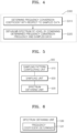
- FIG. 1 is a flowchart illustrating a method of obtaining an MR spectrum of a voxel in an MR image according to the exemplary embodiment of the present invention using the MRI apparatus of FIG. 7 .
- the method of obtaining the MR spectrum of the voxel in an MR image includes configuring a sampling pattern of a k-space data in step S100 sampling predetermined data from the k-space data based on the configured sampling pattern in step S200, and obtaining the MR spectrum of the voxel by using the sampled data in step S300.
- the method of FIG. 1 may be performed by predetermined software operated by the hardware components of the image generating unit 33 in FIG. 7 .
- the user of the MRI apparatus and the present invention enters a selection of the voxel of interest (VOI) on an MR image output by the image outputting unit 36, or enters a selection of a region of interest (ROI) including the VOI for a specific portion of the object such as the patient on the table 15 in the MRI apparatus.
- VOI voxel of interest
- ROI region of interest
- the user interface 31 may include a keyboard and/or a mouse, as well as a display, or may include a touchscreen, with the display connected to or including the image outputting unit 36.
- the display may display a graphic user interface (GUI) for displaying an MR image of the patient or the ROI of the patient, allowing the user to select the VOI or the ROI by selecting a specific region in the MR image.
- GUI graphic user interface
- the user may select the VOI or the ROI by clicking a mouse at the VOI or the ROI, or by touching the touchscreen at a location corresponding to the VOI or the ROI.
- the present invention then performs step S300 using the user selection of the VOI.
- the k-space according to the exemplary embodiment of the present invention refers to a set of raw data that may be used to generate one MR image.
- radio frequency (RF) pulses are applied to the object body and a phase encoding gradient is changed step by step to obtain signals having location information.
- the obtained data is referred to as raw data, and the raw data may include location information and contrast information.
- a signal having a high amplitude may be shown at a center of the k-space along a phase axis and a frequency axis, and the center of the k-space is filled with data having a low spatial resolution due to the phase encoding gradient having a small gradient and may include contrast information of tissue.
- an outer portion of the k-space may show a signal having a low amplitude along the phase axis and the frequency axis, and is filled with data having a high spatial resolution due to the phase encoding gradient having a large gradient to show detailed portions or a boundary between tissues in the MR image.
- a sampling pattern may be configured with respect to the k-space data in step S100. Based on the configured sampling pattern, predetermined data may be sampled from the k-space data in step S200.
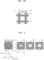
- FIGS. 2A and 2B show full-sampling according to the prior art and sine-pattern type sampling according to an example that does not form part of the present invention, respectively.
- full-sampling 210 may be performed with respect to a k-space 200; however, a speed of processing such data may be reduced.
- the sampling pattern may be configured as, for example, a two-dimensional sinc pattern generated by the well-known sinc waveform shown in (a) of FIG. 3 . That is, using such a sinc pattern, the sine pattern sampling as shown in FIG. 2B may be performed. For example, the sampling may be performed based on the sinc pattern shown in (a) of FIG. 3 in order to use signals having high amplitudes.
- the sampling may be performed by extracting data from the white portions 220. Therefore, an amount of data less than that of the full sampling 210 of FIG. 2A in the prior art may be processed, and thus, using the sampling pattern of FIG. 2B , the data processing speed may be increased and the data processing time may be reduced.
- FIG. 3 shows a sampling pattern consisting of different patterns according to the exemplary embodiment of the present invention.
- the sampling pattern according to the exemplary embodiment includes at least two different patterns according to an energy distribution in k-space data.
- the energy distribution in a k-space 200a has a sinc shape. That is, an amplitude of the sinc shape of the energy distribution is gradually reduced from a region 250 having the highest amplitude.
- the energy distribution in the k-space may be observed as an alternately changeable pattern on a two-dimensional plane.
- the region 250 having the highest amplitude may have the largest energy, and then, the energy distribution may be similar to a reduction of the amplitude corresponding to each of the regions 253, 255, and 257 shown in (a) of FIG. 3 .
- the sampling pattern is differently configured according to the energy distribution in the k-space data.
- a sampling pattern 200b may be configured to include a region 220b corresponding to the regions 250 and 253 of (a) in FIG. 3 .
- the data included in the region 220b may be sampled by using only the sampling pattern 200b.
- five pieces or regions of data included in the region 220b, represented by white regions, may be sampled. That is, data included in a region 230b may not be sampled.
- sampling patterns 200c and 200d may be configured. For example, nine regions of data, represented by white regions, may be sampled by using the sampling pattern 200c, and thirteen regions of data, represented by white regions, may be sampled by using the sampling pattern 200d.
- the configuring of the sampling pattern with respect to the k-space in step S200 of FIG. 1 includes configuring of the sampling pattern so that the k-space data corresponding to a specific voxel of an MR image is included in the sampling pattern.
- An MR image of an object body may be acquired by performing a frequency conversion of the k-space.
- the frequency conversion may include a Fourier inverse transformation.
- a frequency encoding gradient magnetic field and a phase encoding gradient magnetic field in the k-space, generated by the gradient coil 12 in FIG. 7 may provide a location of a signal in the MR image. That is, each piece or region of data in the k-space may configure an image of the MR photographed object body at a predetermined location in the MR image according to the frequency encoding gradient magnetic field and the phase encoding gradient magnetic field in the k-space.
- the k-space data corresponding to the voxel that the user is interested in may be obtained by using the frequency encoding gradient magnetic field and the phase encoding gradient magnetic field, and the sampling pattern may be configured so that the obtained k-space data may be included in the sampling pattern.
- FIG. 4 is a flowchart illustrating a method of obtaining an MR spectrum of a voxel by using sampled data, according to the exemplary embodiment of the present invention.
- the method of FIG. 4 may be performed by predetermined software operated by the hardware components of the image generating unit 33 in FIG. 7 .
- a spectrum of a voxel of interest may be exactly reconstructed by using the sampled data that is sampled based on the above described sampling pattern.
- Each piece of sampled data may differently contribute to the acquisition of the MR spectrum of the VOI, and the MR spectrum of the VOI may be relatively exactly reconstructed according to contribution degrees of each data.
- predetermined coefficients for example, a frequency conversion coefficient, and the like
- the obtaining of the MR spectrum of the voxel by using the sampled data by step S300 in FIG. 1 may include determining a frequency conversion coefficient of the sampled data in step S310, and obtaining the MR spectrum of the voxel by combining the determined frequency conversion coefficient and the sampled data in step S320.
- the k-space data, represented by a variable d, for a frequency f that is sampled based on the above-described sampling pattern in (a) of FIG. 3 may be represented as a linear combination of image information I of the object body, obtained from the signal collecting unit 23 via at least one of the storages 34, 35 in FIG. 7 .
- the image information I in a region of interest (ROI) including the VOI may be represented by using the k-space data and using Equation (2) below.
- S ideal (f) may refer to a spectrum corresponding to the desired image information I.
- S ideal f ⁇ x y ⁇ ROI I f x y
- a predetermined coefficient c that is used to reconstruct the MR spectrum of the VOI may be determined to be approximately equal to S ideal (f) in Equation (2) above. That is, the predetermined coefficient c that will be used to reconstruct the MR spectrum of the VOI may be obtained by using, for example, Equation (3) below.
- S ideal f ⁇ ⁇ kx ky c kx , ky d f kx ky ⁇ x y ⁇ kx ky c kx , ky F kx , ky x y I f x y
- the coefficient c represented by Equation (3) may be determined as a coefficient that minimizes Equation (4) through L2 minimization.
- Equation (5) the coefficient c obtained by using Equation (4) may be normalized by Equation (5) below.
- a relatively exact amount of metabolites may be measured by using the normalized coefficient c norm even when the metabolites in the object body are evenly distributed, and thus, the accuracy of reconstructing the spectrum in the VOI may be adjusted.
- c kx , ky norm c kx , ky / ⁇ x y ⁇ kx ky c kx , ky F kx , ky x y
- the spectrum S in the VOI may be reconstructed as a linear combination represented by using Equation (6) via the coefficients obtained from Equation (5).
- S f ⁇ kx ky c kx , ky norm d f kx ky
- FIG. 5 is a block diagram of an apparatus 500 for obtaining the MR spectrum of the voxel in the MR image, according to the exemplary embodiment of the present invention.
- the apparatus 500 may be implemented in the image generating unit 33 of FIG. 7 .
- the apparatus 500 for obtaining the MR spectrum of the voxel in the MR image includes a sampling pattern configuration unit 510 configuring a sampling pattern of the k-space data, a sampling unit 520 sampling predetermined data from the k-space data based on the configured sampling pattern, and a spectrum obtaining unit 530 obtaining the MR spectrum of the voxel by using the sampled data.
- the sampling pattern according to an example not forming part of the claimed invention may be a sinc pattern, as shown in (a) in FIG. 3 .
- the sampling pattern according to the exemplary embodiment of the present invention is configured to include at least two different patterns according to an energy distribution of the k-space data, as shown in (b), (c), and (d) of FIG. 3 .
- the sampling pattern configuring unit 510 of the exemplary embodiment configures the sampling pattern so that the k-space data corresponding to the voxel of the MR image may be included in the sampling pattern, such as the white or gray regions in (a) of FIG. 3 , or at least one of the white regions in (b), (c), and (d) of FIG. 3 , respectively; for example, the region 220b in (b) of FIG. 3 .
- FIG. 6 is a diagram showing the MR spectrum obtaining unit 530 configured for obtaining the MR spectrum of the voxel in the MR image, according to the exemplary embodiment of the present invention.
- the MR spectrum obtaining unit 530 of the exemplary embodiment may include a frequency coefficient determiner 531 for determining a frequency conversion coefficient of the sampled data.
- the MR spectrum obtaining unit 530 of the exemplary embodiment may obtain the MR spectrum of the voxel by combining the determined frequency conversion coefficient and the sampled data.
- the MR spectrum is then output in step S320 in FIG. 4 by the spectrum obtaining unit 530, by the image outputting unit 36, and optionally by a display or GUI of the user interface 31, so that the user uses the MR spectrum to identify the biochemical distribution of metabolites in a certain voxel, for example, for diagnosing a disease or abnormality at the VOI or ROI of the object corresponding to the voxel.
- non-transitory computer-readable storage medium examples include magnetic storage media (e.g., ROM, floppy disks, hard disks, etc.), optical storage media (e.g., CD-ROMs or DVDs), etc.
- magnetic storage media e.g., ROM, floppy disks, hard disks, etc.
- optical storage media e.g., CD-ROMs or DVDs
- the above-described apparatus and methods according to the present invention can be implemented in hardware or firmware, or as software or computer code, or combinations thereof.
- Various components such as a controller, a central processing unit (CPU), a processor, and any unit or device described herein includes at least hardware and/or other physical structures and elements.
- the software or computer code can also be stored in a non-transitory recording medium such as a CD ROM, a RAM, a ROM whether erasable or rewritable or not, a floppy disk, CDs, DVDs, memory chips, a hard disk, a magnetic storage media, an optical recording media, or a magneto-optical disk or computer code downloaded over a network originally stored on a remote recording medium, a computer readable recording medium, or a non-transitory machine readable medium and to be stored on a local recording medium, so that the methods described herein can be rendered in such software, computer code, software modules, software objects, instructions, applications, applets, apps, etc.
- a non-transitory recording medium such as a CD ROM, a RAM, a ROM whether erasable or rewritable or not, a floppy disk, CDs, DVDs, memory chips, a hard disk, a magnetic storage media, an optical recording media, or a magneto-
- the computer, the processor, microprocessor controller or the programmable hardware include volatile and/or non-volatile storage and memory components, e.g., RAM, ROM, Flash, etc. that may store or receive software or computer code that when accessed and executed by the computer, processor or hardware implement the processing methods described herein.
- volatile and/or non-volatile storage and memory components e.g., RAM, ROM, Flash, etc.
- the execution of the code transforms the general purpose computer into a special purpose computer for executing the processing shown herein.
- the program may be electronically transferred through any medium such as communication signals transmitted by wire/wireless connections, and their equivalents.
- the programs and computer readable recording medium can also be distributed in network-coupled computer systems so that the computer readable code is stored and executed in a distributed fashion.
Landscapes
- Physics & Mathematics (AREA)
- General Physics & Mathematics (AREA)
- High Energy & Nuclear Physics (AREA)
- Condensed Matter Physics & Semiconductors (AREA)
- Spectroscopy & Molecular Physics (AREA)
- Health & Medical Sciences (AREA)
- Engineering & Computer Science (AREA)
- Optics & Photonics (AREA)
- Nuclear Medicine, Radiotherapy & Molecular Imaging (AREA)
- Life Sciences & Earth Sciences (AREA)
- General Health & Medical Sciences (AREA)
- Radiology & Medical Imaging (AREA)
- Medical Informatics (AREA)
- Theoretical Computer Science (AREA)
- Computer Vision & Pattern Recognition (AREA)
- Quality & Reliability (AREA)
- Biophysics (AREA)
- Pathology (AREA)
- Biomedical Technology (AREA)
- Heart & Thoracic Surgery (AREA)
- Molecular Biology (AREA)
- Surgery (AREA)
- Animal Behavior & Ethology (AREA)
- Public Health (AREA)
- Veterinary Medicine (AREA)
- Magnetic Resonance Imaging Apparatus (AREA)
Description
- The present disclosure relates to a method and apparatus for obtaining the magnetic resonance (MR) spectrum of a voxel of an MR image, and more particularly, to a method and apparatus for obtaining an MR spectrum of a single voxel by using sampled data obtained by using a predetermined sampling pattern as defined in the independent claims.
- Magnetic resonance spectroscopy (MRS) is a method of non-invasively obtaining an image of an object body for showing, for example, the distribution of metabolites of body organs or biochemical information.
- An MRS image (MRSI) includes in each image voxel thereof spectrum information of a metabolite. Therefore, in order to understand the distribution of metabolites or biochemical information of body organs, voxels having precise spatial information have to be obtained.
- Single voxel spectroscopy (SVS) is a basic technology for obtaining an MR spectrum of a single voxel in order to identify the biochemical distribution of metabolites in a certain voxel.
- Generally, in SVS, a three-direction selection is performed by using point-resolved spectroscopy (PRESS) pulses with a 90-180-180 degree sequence, and a signal is received from a voxel located at a portion where the three selected directions cross each other to obtain an MR spectrum.
- When the three directions are selected, a chemical shift excitation occurs. Thus, due to the chemical shift excitation, not only biochemical information of the user selected region including the voxel but also information of a region outside of a user selected region may be obtainedTherefore, it is difficult to obtain precise metabolite information or biochemical information of the region including the voxel selected by the user.
- In the prior art, in order to reduce effects caused by the chemical shift excitation, spatial information is obtained through a phase encoding process after performing a single voxel excitation, and only spectrum information of a single voxel region that the user is interested in is obtained. Also, in other prior art, a region that is larger than a single voxel region that the user is interested in is excited, and then, an amount of metabolite, which is reduced due to the chemical shift excitation, is corrected.
- However, according to the above examples in the prior art, a time for acquiring data collected to obtain spatial information may be increased, and a signal-to-noise ratio (SNR) may be reduced.
- In addition to or as alternative for the above identified prior art, reference is made here to an article by MARECI ET AL.: "ESSENTIAL CONSIDERATIONS FOR SPECTRAL LOCALIZATION USING INDIRECT GRADIENT ENCODING OF SPATIAL INFORMATION", JOURNAL OF MAGNETIC RESONANCE, ACADEMIC PRESS, ORLANDO, FL, US, vol. 92, no. 2, 1 April 1991 (1991-04-01), pages 229-246, which discloses a method for localized magnetic resonance spectroscopy with weighted phase encoding.
- Similar methods for localized magnetic resonance spectroscopy are disclosed in SHANTANU SARKAR ET AL.: "Truncation artifact reduction in spectroscopic imaging using a dual-density spiral k-space trajectory", MAGNETIC RESONANCE IMAGING, vol. 20, no. 10, 1 December 2002 (2002-12-01), pages 743-757, in LOFFLER ET AL.: "Localized Spectroscopy from Anatomically Matched Compartments: Improved Sensitivity and Localization for Cardiac 31P MRS in Humans", JOURNAL OF MAGNETIC RESONANCE, ACADEMIC PRESS, ORLANDO, FL, US, vol. 134, no. 2, 1 October 1998 (1998-10-01), pages 287-299, and in XIAOPING HU ET AL.: "SLIM: SPECTRAL LOCALIZATION BY IMAGING", MAGNETIC RESONANCE IN MEDICINE, ACADEMIC PRESS, DULUTH, MN, US, vol. 8, no. 3, 1 November 1988 (1988-11-01), pages 314-322.
- The present invention provides a method and apparatus for obtaining a magnetic resonance (MR) spectrum of a voxel in an MR image, in accordance with the appended independent claims.
- The above and other features and advantages of the present invention will become more apparent by describing in detail exemplary embodiments thereof with reference to the attached drawings in which:
-
FIG. 1 is a flowchart illustrating a method of obtaining a magnetic resonance (MR) spectrum of a voxel in an MR image, according to an exemplary embodiment of the present invention; -
FIGS. 2A and2B are diagrams respectively showing full-sampling according to the prior art and sine-pattern sampling according to an example that does not form part of the claimed invention; -
FIG. 3 is a diagram showing sampling patterns of different shapes, according to the exemplary embodiment of the present invention; -
FIG. 4 is a flowchart illustrating a method of obtaining the MR spectrum of the voxel by using sampled data, according to the exemplary embodiment of the present invention; -
FIG. 5 is a diagram of an apparatus for obtaining the MR spectrum of the voxel in the MR image, according to the exemplary embodiment of the present invention; -
FIG. 6 is a diagram of an MR spectrum obtaining unit for obtaining the MR spectrum of the voxel in the MR image according to the exemplary embodiment of the present invention; and -
FIG. 7 is a diagram of an example MRI apparatus for implementing the present invention. - The terminology used herein will now be briefly described as the present invention will be described in detail based on this terminology.
Terms arbitrarily selected by the applicant of the present invention may also be used in a specific case. In this case, their meanings need to be given in the detailed description of the present invention. Hence, the terms must be defined based on their meanings and the contents of the entire specification, not by simply stating the terms. - It will be understood that the terms "comprises" and/or "comprising" or "includes" and/or "including" when used in this specification, specify the presence of stated elements, but do not preclude the presence or addition of one or more other elements. Terms such as "unit" and "module" stated in the specification refer to units that process at least one function or operation, and they may be implemented by using hardware, software, or a combination of hardware and software.
- The present invention will now be described more fully with reference to the accompanying drawings, in which exemplary embodiments of the present invention are shown. The present invention may, however, be embodied in many different forms and should not be construed as being limited to the exemplary embodiments set forth herein. In the drawings, parts irrelevant to the description are omitted for simplicity of explanation, and like numbers refer to like elements throughout. Expressions such as "at least one of", when preceding a list of elements, modify the entire list of elements and do not modify the individual elements of the list.
- Throughout the specification, the term "magnetic resonance imaging (MRI)" refers to imaging of an object body, which acquires an image, referred to herein as an "MR image", by using magnetic resonance (MR), also known as nuclear magnetic resonance (NMR).
- Throughout the specification, a user may be a medical expert such as a doctor, a nurse, a medical specialist, and a medical imaging expert, or an engineer managing medical appliances; however, the present invention is not limited thereto.
- An object body according to exemplary embodiments of the present invention may be a part of the human body. For example, the object body may be an organ such as the liver, heart, uterus, brain, breast, or abdomen.
- Also, the object body according to exemplary embodiments of the present invention may be a phantom. The phantom refers to a material having a volume, density, and effective physical characteristics nearly equivalent to those characteristics of a living organism, and the phantom according to exemplary embodiments of the present invention may be a spherical phantom having similar properties to those of the human body or a part thereof.
- According to an example that does not form part of the claimed invention, data is sampled in a k-space by using a sinc type pattern, and a phase of the sampled data is obtained to acquire spatial information of a voxel that a user is interested in. Then, an MR spectrum of the voxel that the user is interested in may be obtained by using the sampled data.
- According to single voxel spectroscopy (SVS) in the prior art, a large region, including the voxel that the user is interested in, is set in an MR image to excite an object body, spatial information is acquired through phase encoding of the entire MR image, and then only the voxel that the user is interested in is extracted to acquire the MR spectrum of the voxel. For example, a remaining region except for that of the voxel of interest in the large set region may be truncated to extract the voxel that the user is interested in.
- However, according to the SVS in the prior art, it is necessary to perform many samplings of k-space data, and thus, a time for processing the sampling data and a time for extracting the voxel of interest may increase, and therefore, a signal-to-noise ratio (SNR) according to time may be lowered. The present invention solves these problems to reduce the time of processing of the sampling data and the extraction time, and also to increase the SNR.
- Also, metabolites in the region including the voxel that the user is interested in may not be excited due to a chemical shift excitation. To address this problem, a large region that completely includes the voxel that the user is interested in may be set to excite the object body. In this case, however, signals of metabolites that are included in a region except for the voxel of interest may be further included in the large region. The present invention solves this problem by exactly extracting an MR spectrum of the voxel of interest.
- According to exemplary embodiments of the present invention, a voxel that the user is interested in is reconstructed based on data that is sampled by using a predetermined sampling pattern, and thus, a time for processing data and the extraction time may be reduced, the SNR may be increased, and an MR spectrum of the voxel of interest may be exactly extracted.
- As shown in
FIG. 7 , a magnetic resonance imaging (MRI) apparatus of the present invention may implement the method and the various components of the present invention described inFIGS. 1-6 . The MRI apparatus ofFIG. 7 may include amagnet assembly 14 having a generally cylindrical shape with a hollow bore having a longitudinal axis, into which at least a portion of an object body or a subject, such as a patient, is disposed, for example, on a table 15 which may move the patient into and out of the bore. Themagnet assembly 14 has at least onemain magnet 11, at least onegradient coil 12, and at least one radio frequency (RF)coil 13 disposed around the bore for generating a magnetic field and for receiving an RF signal from the patient or a portion thereof, in a manner known in the art for performing MRI. - The
main magnet 11 generates a main magnetic field, and a firstsignal generating unit 21 controls thegradient coil 12 to generate gradient magnetic fields. The secondsignal generating unit 22 controls theRF coil 13 to generate RF signals emitted to the patient or a portion thereof, and asignal collecting unit 23 receives RF signals from the patent or a portion thereof. At least one of afirst storage 34 and asecond storage 35 are used to receive and at least temporarily store the received RF signals as MRI data, which are sent to animage generating unit 33. Auser interface 31 allows a user, such as a technician, diagnostician, or medical staff to control and send commands to acontrol unit 32 which controls thesignal generating units image generating unit 33. Using the received RF signals, theimage generating unit 33 generates an MR image of the patent or a portion thereof, which is output by animage outputting unit 36, which may be a display, or which may transmit the image to a network to other facilities or devices in communication with the MRI apparatus, or the image may be transmitted to another storage which may be external to the MRI apparatus. -
FIG. 1 is a flowchart illustrating a method of obtaining an MR spectrum of a voxel in an MR image according to the exemplary embodiment of the present invention using the MRI apparatus ofFIG. 7 . - The method of obtaining the MR spectrum of the voxel in an MR image according to the exemplary embodiment of the present invention includes configuring a sampling pattern of a k-space data in step S100 sampling predetermined data from the k-space data based on the configured sampling pattern in step S200, and obtaining the MR spectrum of the voxel by using the sampled data in step S300. The method of
FIG. 1 may be performed by predetermined software operated by the hardware components of theimage generating unit 33 inFIG. 7 . Using theuser interface 31, the user of the MRI apparatus and the present invention enters a selection of the voxel of interest (VOI) on an MR image output by theimage outputting unit 36, or enters a selection of a region of interest (ROI) including the VOI for a specific portion of the object such as the patient on the table 15 in the MRI apparatus. - The
user interface 31 may include a keyboard and/or a mouse, as well as a display, or may include a touchscreen, with the display connected to or including theimage outputting unit 36. The display may display a graphic user interface (GUI) for displaying an MR image of the patient or the ROI of the patient, allowing the user to select the VOI or the ROI by selecting a specific region in the MR image. For example, the user may select the VOI or the ROI by clicking a mouse at the VOI or the ROI, or by touching the touchscreen at a location corresponding to the VOI or the ROI. The present invention then performs step S300 using the user selection of the VOI. - The k-space according to the exemplary embodiment of the present invention refers to a set of raw data that may be used to generate one MR image.
- Using the MRI apparatus shown in
FIG. 7 , radio frequency (RF) pulses are applied to the object body and a phase encoding gradient is changed step by step to obtain signals having location information. The obtained data is referred to as raw data, and the raw data may include location information and contrast information. - A signal having a high amplitude may be shown at a center of the k-space along a phase axis and a frequency axis, and the center of the k-space is filled with data having a low spatial resolution due to the phase encoding gradient having a small gradient and may include contrast information of tissue.
- Also, an outer portion of the k-space may show a signal having a low amplitude along the phase axis and the frequency axis, and is filled with data having a high spatial resolution due to the phase encoding gradient having a large gradient to show detailed portions or a boundary between tissues in the MR image.
- According to the exemplary embodiment of the present invention, a sampling pattern may be configured with respect to the k-space data in step S100. Based on the configured sampling pattern, predetermined data may be sampled from the k-space data in step S200.
-
FIGS. 2A and2B show full-sampling according to the prior art and sine-pattern type sampling according to an example that does not form part of the present invention, respectively. - As shown in the prior art in
FIG. 2A , full-sampling 210 may be performed with respect to a k-space 200; however, a speed of processing such data may be reduced. - According to an example that does not form part of the claimed invention in
FIG. 2B , the sampling pattern may be configured as, for example, a two-dimensional sinc pattern generated by the well-known sinc waveform shown in (a) ofFIG. 3 . That is, using such a sinc pattern, the sine pattern sampling as shown inFIG. 2B may be performed. For example, the sampling may be performed based on the sinc pattern shown in (a) ofFIG. 3 in order to use signals having high amplitudes. - Referring to
FIG. 2B , there is no need to extract data from theblack portion 230, and the sampling may be performed by extracting data from thewhite portions 220. Therefore, an amount of data less than that of thefull sampling 210 ofFIG. 2A in the prior art may be processed, and thus, using the sampling pattern ofFIG. 2B , the data processing speed may be increased and the data processing time may be reduced. -
FIG. 3 shows a sampling pattern consisting of different patterns according to the exemplary embodiment of the present invention. - The sampling pattern according to the exemplary embodiment includes at least two different patterns according to an energy distribution in k-space data.
- As shown in (a) of
FIG. 3 , the energy distribution in a k-space 200a has a sinc shape. That is, an amplitude of the sinc shape of the energy distribution is gradually reduced from aregion 250 having the highest amplitude. For example, as shown in (a) ofFIG. 3 , the energy distribution in the k-space may be observed as an alternately changeable pattern on a two-dimensional plane. - For example, the
region 250 having the highest amplitude may have the largest energy, and then, the energy distribution may be similar to a reduction of the amplitude corresponding to each of theregions FIG. 3 . - As described above, the sampling pattern is differently configured according to the energy distribution in the k-space data.
- For example, as shown in (b) of
FIG. 3 , asampling pattern 200b may be configured to include aregion 220b corresponding to theregions FIG. 3 . The data included in theregion 220b may be sampled by using only thesampling pattern 200b. In this example, five pieces or regions of data included in theregion 220b, represented by white regions, may be sampled. That is, data included in aregion 230b may not be sampled. - Also, as shown in (c) and (d) of
FIG. 3 ,sampling patterns sampling pattern 200c, and thirteen regions of data, represented by white regions, may be sampled by using thesampling pattern 200d. - According to the exemplary embodiment of the present invention, the configuring of the sampling pattern with respect to the k-space in step S200 of
FIG. 1 includes configuring of the sampling pattern so that the k-space data corresponding to a specific voxel of an MR image is included in the sampling pattern. - An MR image of an object body may be acquired by performing a frequency conversion of the k-space. For example, the frequency conversion may include a Fourier inverse transformation.
- A frequency encoding gradient magnetic field and a phase encoding gradient magnetic field in the k-space, generated by the
gradient coil 12 inFIG. 7 , may provide a location of a signal in the MR image. That is, each piece or region of data in the k-space may configure an image of the MR photographed object body at a predetermined location in the MR image according to the frequency encoding gradient magnetic field and the phase encoding gradient magnetic field in the k-space. - Therefore, the k-space data corresponding to the voxel that the user is interested in may be obtained by using the frequency encoding gradient magnetic field and the phase encoding gradient magnetic field, and the sampling pattern may be configured so that the obtained k-space data may be included in the sampling pattern.
-
FIG. 4 is a flowchart illustrating a method of obtaining an MR spectrum of a voxel by using sampled data, according to the exemplary embodiment of the present invention. The method ofFIG. 4 may be performed by predetermined software operated by the hardware components of theimage generating unit 33 inFIG. 7 . - According to the exemplary embodiment of the present invention, a spectrum of a voxel of interest (VOI) may be exactly reconstructed by using the sampled data that is sampled based on the above described sampling pattern.
- Each piece of sampled data may differently contribute to the acquisition of the MR spectrum of the VOI, and the MR spectrum of the VOI may be relatively exactly reconstructed according to contribution degrees of each data. For example, in order to exactly reconstruct the MR spectrum of the VOI, predetermined coefficients (for example, a frequency conversion coefficient, and the like) that will be used in a reconstruction process have to be determined.
- According to the exemplary embodiment of the present invention, referring to
FIG. 4 , the obtaining of the MR spectrum of the voxel by using the sampled data by step S300 inFIG. 1 may include determining a frequency conversion coefficient of the sampled data in step S310, and obtaining the MR spectrum of the voxel by combining the determined frequency conversion coefficient and the sampled data in step S320. - The k-space data, represented by a variable d, for a frequency f that is sampled based on the above-described sampling pattern in (a) of
FIG. 3 may be represented as a linear combination of image information I of the object body, obtained from thesignal collecting unit 23 via at least one of thestorages FIG. 7 . The linear combination may be represented by using Equation (1) via, for example, Fourier coefficients F.
- The image information I in a region of interest (ROI) including the VOI may be represented by using the k-space data and using Equation (2) below. Here, Sideal(f) may refer to a spectrum corresponding to the desired image information I.

- Therefore, a predetermined coefficient c that is used to reconstruct the MR spectrum of the VOI may be determined to be approximately equal to Sideal(f) in Equation (2) above. That is, the predetermined coefficient c that will be used to reconstruct the MR spectrum of the VOI may be obtained by using, for example, Equation (3) below.

- Also, the coefficient c represented by Equation (3) may be determined as a coefficient that minimizes Equation (4) through L2 minimization.

- Also, the coefficient c obtained by using Equation (4) may be normalized by Equation (5) below. A relatively exact amount of metabolites may be measured by using the normalized coefficient cnorm even when the metabolites in the object body are evenly distributed, and thus, the accuracy of reconstructing the spectrum in the VOI may be adjusted.

- For example, the spectrum S in the VOI may be reconstructed as a linear combination represented by using Equation (6) via the coefficients obtained from Equation (5).

-
FIG. 5 is a block diagram of anapparatus 500 for obtaining the MR spectrum of the voxel in the MR image, according to the exemplary embodiment of the present invention. Theapparatus 500 may be implemented in theimage generating unit 33 ofFIG. 7 . - The
apparatus 500 for obtaining the MR spectrum of the voxel in the MR image includes a samplingpattern configuration unit 510 configuring a sampling pattern of the k-space data, asampling unit 520 sampling predetermined data from the k-space data based on the configured sampling pattern, and aspectrum obtaining unit 530 obtaining the MR spectrum of the voxel by using the sampled data. - The sampling pattern according to an example not forming part of the claimed invention may be a sinc pattern, as shown in (a) in
FIG. 3 . - The sampling pattern according to the exemplary embodiment of the present invention is configured to include at least two different patterns according to an energy distribution of the k-space data, as shown in (b), (c), and (d) of
FIG. 3 . - The sampling
pattern configuring unit 510 of the exemplary embodiment configures the sampling pattern so that the k-space data corresponding to the voxel of the MR image may be included in the sampling pattern, such as the white or gray regions in (a) ofFIG. 3 , or at least one of the white regions in (b), (c), and (d) ofFIG. 3 , respectively; for example, theregion 220b in (b) ofFIG. 3 . -
FIG. 6 is a diagram showing the MRspectrum obtaining unit 530 configured for obtaining the MR spectrum of the voxel in the MR image, according to the exemplary embodiment of the present invention. - The MR
spectrum obtaining unit 530 of the exemplary embodiment may include afrequency coefficient determiner 531 for determining a frequency conversion coefficient of the sampled data. - The MR
spectrum obtaining unit 530 of the exemplary embodiment may obtain the MR spectrum of the voxel by combining the determined frequency conversion coefficient and the sampled data. The MR spectrum is then output in step S320 inFIG. 4 by thespectrum obtaining unit 530, by theimage outputting unit 36, and optionally by a display or GUI of theuser interface 31, so that the user uses the MR spectrum to identify the biochemical distribution of metabolites in a certain voxel, for example, for diagnosing a disease or abnormality at the VOI or ROI of the object corresponding to the voxel. - Descriptions of the above method may be included in the description of the apparatus according to the embodiments of the present invention. Thus, descriptions of like elements are not provided again.
- The above-described embodiments of the present invention may be written as computer programs and may be implemented in general-use digital computers that execute the programs by using a non-transitory computer-readable storage medium.
- Examples of the non-transitory computer-readable storage medium include magnetic storage media (e.g., ROM, floppy disks, hard disks, etc.), optical storage media (e.g., CD-ROMs or DVDs), etc.
- The above-described apparatus and methods according to the present invention can be implemented in hardware or firmware, or as software or computer code, or combinations thereof. Various components such as a controller, a central processing unit (CPU), a processor, and any unit or device described herein includes at least hardware and/or other physical structures and elements. In addition, the software or computer code can also be stored in a non-transitory recording medium such as a CD ROM, a RAM, a ROM whether erasable or rewritable or not, a floppy disk, CDs, DVDs, memory chips, a hard disk, a magnetic storage media, an optical recording media, or a magneto-optical disk or computer code downloaded over a network originally stored on a remote recording medium, a computer readable recording medium, or a non-transitory machine readable medium and to be stored on a local recording medium, so that the methods described herein can be rendered in such software, computer code, software modules, software objects, instructions, applications, applets, apps, etc. that is stored on the recording medium using a general purpose computer, a digital computer, or a special processor or in programmable or dedicated hardware, such as an ASIC or FPGA. As would be understood in the art, the computer, the processor, microprocessor controller or the programmable hardware include volatile and/or non-volatile storage and memory components, e.g., RAM, ROM, Flash, etc. that may store or receive software or computer code that when accessed and executed by the computer, processor or hardware implement the processing methods described herein. In addition, it would be recognized that when a general purpose computer accesses code for implementing the processing shown herein, the execution of the code transforms the general purpose computer into a special purpose computer for executing the processing shown herein. In addition, the program may be electronically transferred through any medium such as communication signals transmitted by wire/wireless connections, and their equivalents. The programs and computer readable recording medium can also be distributed in network-coupled computer systems so that the computer readable code is stored and executed in a distributed fashion.
- While the present invention has been particularly shown and described with reference to exemplary embodiments thereof, it will be understood by those of ordinary skill in the art that various changes in form and details may be made therein without departing from the scope of the present invention as defined by the following claims.
Claims (4)
- A method of obtaining a magnetic resonance, "MR," spectrum of a voxel in an MR image of an object, the method comprising:generating, based on MRI data corresponding to RF signals received from the object, an MR image for display on an image outputting unit (36);accepting, via a user interface (31), a selection of a voxel of interest "VOI" or a region of interest "ROI" including the VOI, on the MR image output by the image outputting unit (36), for a specific portion of the object;configuring (S100) a sampling pattern of k-space data that includes the VOI in the MR image;sampling (S200) predetermined data from the k-space data based on the configured sampling pattern;obtaining (S300) an MR spectrum of the VOI by using the sampled data; anddisplaying the MR spectrum of the VOI on the image outputting unit (36),characterized in that the sampling pattern includes at least two different patterns configured according to a sine-shaped energy distribution of the k-space data to be sampled.
- The method of claim 1, wherein the obtaining (S300) of the MR spectrum of the VOI by using the sampled data comprises:determining a frequency conversion coefficient c with respect to the sampled data; andreconstructing the MR spectrum of the VOI by combining the determined frequency conversion coefficient c and the sampled data,wherein the frequency conversion coefficient c used to reconstruct the MR spectrum is determined from:
 wherein Sideal(f) refers to a spectrum corresponding to image information 1, k-space data is represented by variable d for a frequency f that is sampled based on the sampling pattern, kx and ky represents x-axis and y-axis coordinates of the k-space data respectively, and Fourier coefficients are represented by F, with
 wherein the coefficient c is determined as the coefficient that minimizes through L2 minimization the equation of:
- An apparatus configured for obtaining a magnetic resonance, "MR," spectrum of a voxel in an MR image of an object, the apparatus comprising:an image outputting unit (36) configured to display an MR image generated based on MRI data corresponding to RF signals received from the object, and to display the obtained MR spectrum;a user interface (31) configured to accept a selection of a voxel of interest "VOI" or a region of interest "ROI" including the VOI in the MR image, for a specific portion of the object;a sampling pattern configuring unit (510) configured for configuring a sampling pattern of k-space data that includes the VOI in the MR image;a sampling unit (520) configured for sampling predetermined data from the k-space data based on the configured sampling pattern;a spectrum obtaining unit (530) configured for obtaining an MR spectrum of the VOI by using the sampled data;characterized in that the sampling pattern includes at least two different patterns configured according to a sine-shaped energy distribution of the k-space data to be sampled.
- The apparatus of claim 3, wherein the spectrum obtaining unit comprises a frequency coefficient determiner for determining a frequency conversion coefficient of the sampled data, and the spectrum obtaining unit reconstructs an MR spectrum of the VOI by combining the determined frequency conversion coefficient c and the sampled data,wherein the frequency conversion coefficient c used to reconstruct the MR spectrum is determined from:
 wherein Sideal(f) refers to a spectrum corresponding to image information 1, k-space data is represented by variable d for a frequency f that is sampled based on the sampling pattern, kx and ky represents x-axis and y-axis coordinates of the k-space data respectively, and Fourier coefficients are represented by F, with
 and wherein the coefficient c is determined as the coefficient that minimizes through L2 minimization the equation of:
Applications Claiming Priority (1)
| Application Number | Priority Date | Filing Date | Title |
|---|---|---|---|
| KR1020130018237A KR101471979B1 (en) | 2013-02-20 | 2013-02-20 | The method and apparatus for obtaining magnetic resonance spectrum of a voxel of a magnetic resonance image |
Publications (2)
| Publication Number | Publication Date |
|---|---|
| EP2770338A1 EP2770338A1 (en) | 2014-08-27 |
| EP2770338B1 true EP2770338B1 (en) | 2023-08-23 |
Family
ID=49515273
Family Applications (1)
| Application Number | Title | Priority Date | Filing Date |
|---|---|---|---|
| EP13191445.9A Active EP2770338B1 (en) | 2013-02-20 | 2013-11-04 | Method and apparatus for obtaining a magnetic resonance spectrum of a voxel in a magnetic resonance image |
Country Status (4)
| Country | Link |
|---|---|
| US (1) | US9218659B2 (en) |
| EP (1) | EP2770338B1 (en) |
| KR (1) | KR101471979B1 (en) |
| CN (1) | CN104000590B (en) |
Families Citing this family (5)
| Publication number | Priority date | Publication date | Assignee | Title |
|---|---|---|---|---|
| CN106600579A (en) * | 2016-11-30 | 2017-04-26 | 上海联影医疗科技有限公司 | Magnetic resonance image wave spectrum analysis method and device |
| EP3583436B1 (en) | 2017-02-14 | 2022-09-28 | The United States of America, as represented by the Secretary, Department of Health and Human Services | Denoising of dynamic magnetic resonance spectroscopic imaging using low rank approximations in the kinetic domain |
| US10802096B2 (en) | 2017-12-26 | 2020-10-13 | Uih America, Inc. | Methods and systems for magnetic resonance imaging |
| KR102146810B1 (en) * | 2018-10-12 | 2020-08-21 | 연세대학교 원주산학협력단 | Apparatus and method for brain network analysis using magnetic resonance spectroscopy |
| KR102158268B1 (en) * | 2018-11-15 | 2020-09-21 | 연세대학교 원주산학협력단 | Apparatus and method for brain metabolism analysis and brain network implementation |
Family Cites Families (14)
| Publication number | Priority date | Publication date | Assignee | Title |
|---|---|---|---|---|
| US4480228A (en) | 1982-10-15 | 1984-10-30 | General Electric Company | Selective volume method for performing localized NMR spectroscopy |
| US5072182A (en) | 1989-07-13 | 1991-12-10 | Diasonics, Inc. | Fourier shifting of voxel boundaries in MR chemical shift imaging spectroscopy |
| US5804966A (en) | 1996-09-10 | 1998-09-08 | General Electric Company | Volume spectroscopy having image artifact reduction |
| JP4101300B2 (en) * | 1996-12-23 | 2008-06-18 | コーニンクレッカ フィリップス エレクトロニクス エヌ ヴィ | Spectroscopy magnetic resonance imaging method and apparatus |
| US6137290A (en) | 1998-02-19 | 2000-10-24 | General Electric Company | Magnetic resonance spectroscopic imaging having reduced chemical shift error |
| US6541971B1 (en) | 2001-06-28 | 2003-04-01 | Koninklijke Philips Electronics, N.V. | Multi-dimensional spatial NMR excitation |
| US7319784B2 (en) | 2003-02-05 | 2008-01-15 | National Research Council Of Canada | Magnetic resonance spectroscopy using a conformal voxel |
| WO2005000116A1 (en) * | 2003-06-30 | 2005-01-06 | Hitachi Medical Corporation | Magnetic resonance imaging apparatus |
| US7408345B2 (en) * | 2006-02-06 | 2008-08-05 | The Board Of Trustees Of The Leland Stanford Junior University | Generalized MRI reconstruction with correction for multiple image distortion |
| US7411396B1 (en) * | 2006-05-08 | 2008-08-12 | General Electric Company | Method and system of magnetic resonance spectroscopy with volume element dissection |
| US20090285463A1 (en) * | 2008-04-18 | 2009-11-19 | Ricardo Otazo | Superresolution parallel magnetic resonance imaging |
| WO2011085739A1 (en) * | 2010-01-18 | 2011-07-21 | MAX-PLANCK-Gesellschaft zur Förderung der Wissenschaften e.V. | Method and device for magnetic resonance spectroscopic imaging |
| JP5595873B2 (en) * | 2010-10-29 | 2014-09-24 | ジーイー・メディカル・システムズ・グローバル・テクノロジー・カンパニー・エルエルシー | Magnetic resonance imaging apparatus, sampling pattern creation method, and program |
| JP5595872B2 (en) * | 2010-10-29 | 2014-09-24 | ジーイー・メディカル・システムズ・グローバル・テクノロジー・カンパニー・エルエルシー | Magnetic resonance imaging apparatus and program |
-
2013
- 2013-02-20 KR KR1020130018237A patent/KR101471979B1/en active Active
- 2013-06-26 US US13/927,427 patent/US9218659B2/en active Active
- 2013-11-04 EP EP13191445.9A patent/EP2770338B1/en active Active
-
2014
- 2014-02-20 CN CN201410057498.5A patent/CN104000590B/en active Active
Also Published As
| Publication number | Publication date |
|---|---|
| KR20140104630A (en) | 2014-08-29 |
| CN104000590A (en) | 2014-08-27 |
| US9218659B2 (en) | 2015-12-22 |
| KR101471979B1 (en) | 2014-12-15 |
| CN104000590B (en) | 2016-08-17 |
| EP2770338A1 (en) | 2014-08-27 |
| US20140233813A1 (en) | 2014-08-21 |
Similar Documents
| Publication | Publication Date | Title |
|---|---|---|
| JP6211104B2 (en) | System and method for performing tomographic image acquisition and reconstruction | |
| JP4863610B2 (en) | Method for creating a standard measurement protocol for a tomographic imaging system, a computer readable recording medium recording a computer program, and a planning method for positioning an imaging range of an actual object in the tomographic imaging system | |
| US9964621B2 (en) | Methods and apparatus for reducing scan time of phase contrast MRI | |
| JP6055425B2 (en) | Restriction of imaging area for MRI in inhomogeneous magnetic field | |
| US10379189B2 (en) | Simultaneous magnetic resonance angiography and perfusion with nuclear magnetic resonance fingerprinting | |
| JP5942268B2 (en) | Magnetic resonance imaging apparatus and magnetic resonance imaging method | |
| CN111223563B (en) | Medical image diagnosis device and medical image diagnosis system | |
| US11585883B2 (en) | Method and apparatus for high value magnetic resonance imaging | |
| JP7039194B2 (en) | Magnetic resonance imaging equipment and medical image processing equipment | |
| US9218659B2 (en) | Method and apparatus for obtaining a magnetic resonance spectrum of a voxel in a magnetic resonance image | |
| EP3764285A1 (en) | Deep learning of electrical properties tomography | |
| US10362961B2 (en) | System and method for neutral contrast magnetic resonance imaging of calcifications | |
| CN102573625A (en) | Magnetic resonance imaging device, magnetic resonance imaging method, and image display device | |
| JP7663593B2 (en) | Magnetic resonance imaging of breast microcalcifications | |
| JP7792194B2 (en) | Image generation device, image generation method, and image generation program | |
| JPWO2017134830A1 (en) | Medical image diagnosis support apparatus and magnetic resonance imaging apparatus | |
| US12262982B2 (en) | Systems and methods for detecting small physiological or pathological changes using high resolution magnetic resonance imaging | |
| WO2015170394A1 (en) | Image capturing device, image processing device, and image processing method | |
| CN114097041A (en) | Uncertainty map for deep learning electrical characteristic tomography | |
| EP4657105A1 (en) | Turbo field echo magnetic resonance imaging with an initial spin echo preparatory pulse | |
| WO2019238466A1 (en) | Electrical properties tomography mapping of conductivity changes | |
| US20220309669A1 (en) | Medical image diagnosis system and non-transitory computer-readable storage medium storing therein image processing program | |
| JP2024067862A (en) | DATA GENERATION APPARATUS, DATA GENERATION METHOD, DATA GENERATION PROGRAM, AND MEDICAL IMAGE DIAGNOSIS APPARATUS | |
| JP2021518222A (en) | (3-n) dimension identification of conductivity |
Legal Events
| Date | Code | Title | Description |
|---|---|---|---|
| PUAI | Public reference made under article 153(3) epc to a published international application that has entered the european phase |
Free format text: ORIGINAL CODE: 0009012 |
|
| 17P | Request for examination filed |
Effective date: 20131104 |
|
| AK | Designated contracting states |
Kind code of ref document: A1 Designated state(s): AL AT BE BG CH CY CZ DE DK EE ES FI FR GB GR HR HU IE IS IT LI LT LU LV MC MK MT NL NO PL PT RO RS SE SI SK SM TR |
|
| AX | Request for extension of the european patent |
Extension state: BA ME |
|
| RBV | Designated contracting states (corrected) |
Designated state(s): AL AT BE BG CH CY CZ DE DK EE ES FI FR GB GR HR HU IE IS IT LI LT LU LV MC MK MT NL NO PL PT RO RS SE SI SK SM TR |
|
| STAA | Information on the status of an ep patent application or granted ep patent |
Free format text: STATUS: EXAMINATION IS IN PROGRESS |
|
| 17Q | First examination report despatched |
Effective date: 20190612 |
|
| GRAP | Despatch of communication of intention to grant a patent |
Free format text: ORIGINAL CODE: EPIDOSNIGR1 |
|
| STAA | Information on the status of an ep patent application or granted ep patent |
Free format text: STATUS: GRANT OF PATENT IS INTENDED |
|
| INTG | Intention to grant announced |
Effective date: 20230531 |
|
| RAP3 | Party data changed (applicant data changed or rights of an application transferred) |
Owner name: INDUSTRY-ACADEMIC COOPERATION FOUNDATION YONSEI UNIVERSITY Owner name: SAMSUNG ELECTRONICS CO., LTD. |
|
| GRAS | Grant fee paid |
Free format text: ORIGINAL CODE: EPIDOSNIGR3 |
|
| GRAA | (expected) grant |
Free format text: ORIGINAL CODE: 0009210 |
|
| STAA | Information on the status of an ep patent application or granted ep patent |
Free format text: STATUS: THE PATENT HAS BEEN GRANTED |
|
| AK | Designated contracting states |
Kind code of ref document: B1 Designated state(s): AL AT BE BG CH CY CZ DE DK EE ES FI FR GB GR HR HU IE IS IT LI LT LU LV MC MK MT NL NO PL PT RO RS SE SI SK SM TR |
|
| REG | Reference to a national code |
Ref country code: GB Ref legal event code: FG4D |
|
| REG | Reference to a national code |
Ref country code: CH Ref legal event code: EP |
|
| REG | Reference to a national code |
Ref country code: DE Ref legal event code: R096 Ref document number: 602013084490 Country of ref document: DE |
|
| REG | Reference to a national code |
Ref country code: IE Ref legal event code: FG4D |
|
| REG | Reference to a national code |
Ref country code: LT Ref legal event code: MG9D |
|
| REG | Reference to a national code |
Ref country code: NL Ref legal event code: MP Effective date: 20230823 |
|
| REG | Reference to a national code |
Ref country code: AT Ref legal event code: MK05 Ref document number: 1603220 Country of ref document: AT Kind code of ref document: T Effective date: 20230823 |
|
| PG25 | Lapsed in a contracting state [announced via postgrant information from national office to epo] |
Ref country code: GR Free format text: LAPSE BECAUSE OF FAILURE TO SUBMIT A TRANSLATION OF THE DESCRIPTION OR TO PAY THE FEE WITHIN THE PRESCRIBED TIME-LIMIT Effective date: 20231124 |
|
| PG25 | Lapsed in a contracting state [announced via postgrant information from national office to epo] |
Ref country code: IS Free format text: LAPSE BECAUSE OF FAILURE TO SUBMIT A TRANSLATION OF THE DESCRIPTION OR TO PAY THE FEE WITHIN THE PRESCRIBED TIME-LIMIT Effective date: 20231223 |
|
| PG25 | Lapsed in a contracting state [announced via postgrant information from national office to epo] |
Ref country code: SE Free format text: LAPSE BECAUSE OF FAILURE TO SUBMIT A TRANSLATION OF THE DESCRIPTION OR TO PAY THE FEE WITHIN THE PRESCRIBED TIME-LIMIT Effective date: 20230823 Ref country code: RS Free format text: LAPSE BECAUSE OF FAILURE TO SUBMIT A TRANSLATION OF THE DESCRIPTION OR TO PAY THE FEE WITHIN THE PRESCRIBED TIME-LIMIT Effective date: 20230823 Ref country code: PT Free format text: LAPSE BECAUSE OF FAILURE TO SUBMIT A TRANSLATION OF THE DESCRIPTION OR TO PAY THE FEE WITHIN THE PRESCRIBED TIME-LIMIT Effective date: 20231226 Ref country code: NO Free format text: LAPSE BECAUSE OF FAILURE TO SUBMIT A TRANSLATION OF THE DESCRIPTION OR TO PAY THE FEE WITHIN THE PRESCRIBED TIME-LIMIT Effective date: 20231123 Ref country code: NL Free format text: LAPSE BECAUSE OF FAILURE TO SUBMIT A TRANSLATION OF THE DESCRIPTION OR TO PAY THE FEE WITHIN THE PRESCRIBED TIME-LIMIT Effective date: 20230823 Ref country code: LV Free format text: LAPSE BECAUSE OF FAILURE TO SUBMIT A TRANSLATION OF THE DESCRIPTION OR TO PAY THE FEE WITHIN THE PRESCRIBED TIME-LIMIT Effective date: 20230823 Ref country code: LT Free format text: LAPSE BECAUSE OF FAILURE TO SUBMIT A TRANSLATION OF THE DESCRIPTION OR TO PAY THE FEE WITHIN THE PRESCRIBED TIME-LIMIT Effective date: 20230823 Ref country code: IS Free format text: LAPSE BECAUSE OF FAILURE TO SUBMIT A TRANSLATION OF THE DESCRIPTION OR TO PAY THE FEE WITHIN THE PRESCRIBED TIME-LIMIT Effective date: 20231223 Ref country code: HR Free format text: LAPSE BECAUSE OF FAILURE TO SUBMIT A TRANSLATION OF THE DESCRIPTION OR TO PAY THE FEE WITHIN THE PRESCRIBED TIME-LIMIT Effective date: 20230823 Ref country code: GR Free format text: LAPSE BECAUSE OF FAILURE TO SUBMIT A TRANSLATION OF THE DESCRIPTION OR TO PAY THE FEE WITHIN THE PRESCRIBED TIME-LIMIT Effective date: 20231124 Ref country code: FI Free format text: LAPSE BECAUSE OF FAILURE TO SUBMIT A TRANSLATION OF THE DESCRIPTION OR TO PAY THE FEE WITHIN THE PRESCRIBED TIME-LIMIT Effective date: 20230823 Ref country code: AT Free format text: LAPSE BECAUSE OF FAILURE TO SUBMIT A TRANSLATION OF THE DESCRIPTION OR TO PAY THE FEE WITHIN THE PRESCRIBED TIME-LIMIT Effective date: 20230823 |
|
| PG25 | Lapsed in a contracting state [announced via postgrant information from national office to epo] |
Ref country code: PL Free format text: LAPSE BECAUSE OF FAILURE TO SUBMIT A TRANSLATION OF THE DESCRIPTION OR TO PAY THE FEE WITHIN THE PRESCRIBED TIME-LIMIT Effective date: 20230823 |
|
| PG25 | Lapsed in a contracting state [announced via postgrant information from national office to epo] |
Ref country code: ES Free format text: LAPSE BECAUSE OF FAILURE TO SUBMIT A TRANSLATION OF THE DESCRIPTION OR TO PAY THE FEE WITHIN THE PRESCRIBED TIME-LIMIT Effective date: 20230823 |
|
| PG25 | Lapsed in a contracting state [announced via postgrant information from national office to epo] |
Ref country code: SM Free format text: LAPSE BECAUSE OF FAILURE TO SUBMIT A TRANSLATION OF THE DESCRIPTION OR TO PAY THE FEE WITHIN THE PRESCRIBED TIME-LIMIT Effective date: 20230823 Ref country code: RO Free format text: LAPSE BECAUSE OF FAILURE TO SUBMIT A TRANSLATION OF THE DESCRIPTION OR TO PAY THE FEE WITHIN THE PRESCRIBED TIME-LIMIT Effective date: 20230823 Ref country code: ES Free format text: LAPSE BECAUSE OF FAILURE TO SUBMIT A TRANSLATION OF THE DESCRIPTION OR TO PAY THE FEE WITHIN THE PRESCRIBED TIME-LIMIT Effective date: 20230823 Ref country code: EE Free format text: LAPSE BECAUSE OF FAILURE TO SUBMIT A TRANSLATION OF THE DESCRIPTION OR TO PAY THE FEE WITHIN THE PRESCRIBED TIME-LIMIT Effective date: 20230823 Ref country code: DK Free format text: LAPSE BECAUSE OF FAILURE TO SUBMIT A TRANSLATION OF THE DESCRIPTION OR TO PAY THE FEE WITHIN THE PRESCRIBED TIME-LIMIT Effective date: 20230823 Ref country code: CZ Free format text: LAPSE BECAUSE OF FAILURE TO SUBMIT A TRANSLATION OF THE DESCRIPTION OR TO PAY THE FEE WITHIN THE PRESCRIBED TIME-LIMIT Effective date: 20230823 Ref country code: SK Free format text: LAPSE BECAUSE OF FAILURE TO SUBMIT A TRANSLATION OF THE DESCRIPTION OR TO PAY THE FEE WITHIN THE PRESCRIBED TIME-LIMIT Effective date: 20230823 |
|
| REG | Reference to a national code |
Ref country code: DE Ref legal event code: R097 Ref document number: 602013084490 Country of ref document: DE |
|
| PG25 | Lapsed in a contracting state [announced via postgrant information from national office to epo] |
Ref country code: IT Free format text: LAPSE BECAUSE OF FAILURE TO SUBMIT A TRANSLATION OF THE DESCRIPTION OR TO PAY THE FEE WITHIN THE PRESCRIBED TIME-LIMIT Effective date: 20230823 |
|
| PLBE | No opposition filed within time limit |
Free format text: ORIGINAL CODE: 0009261 |
|
| STAA | Information on the status of an ep patent application or granted ep patent |
Free format text: STATUS: NO OPPOSITION FILED WITHIN TIME LIMIT |
|
| REG | Reference to a national code |
Ref country code: CH Ref legal event code: PL |
|
| PG25 | Lapsed in a contracting state [announced via postgrant information from national office to epo] |
Ref country code: MC Free format text: LAPSE BECAUSE OF FAILURE TO SUBMIT A TRANSLATION OF THE DESCRIPTION OR TO PAY THE FEE WITHIN THE PRESCRIBED TIME-LIMIT Effective date: 20230823 |
|
| PG25 | Lapsed in a contracting state [announced via postgrant information from national office to epo] |
Ref country code: LU Free format text: LAPSE BECAUSE OF NON-PAYMENT OF DUE FEES Effective date: 20231104 |
|
| PG25 | Lapsed in a contracting state [announced via postgrant information from national office to epo] |
Ref country code: CH Free format text: LAPSE BECAUSE OF NON-PAYMENT OF DUE FEES Effective date: 20231130 |
|
| GBPC | Gb: european patent ceased through non-payment of renewal fee |
Effective date: 20231123 |
|
| 26N | No opposition filed |
Effective date: 20240524 |
|
| PG25 | Lapsed in a contracting state [announced via postgrant information from national office to epo] |
Ref country code: MC Free format text: LAPSE BECAUSE OF FAILURE TO SUBMIT A TRANSLATION OF THE DESCRIPTION OR TO PAY THE FEE WITHIN THE PRESCRIBED TIME-LIMIT Effective date: 20230823 Ref country code: LU Free format text: LAPSE BECAUSE OF NON-PAYMENT OF DUE FEES Effective date: 20231104 Ref country code: CH Free format text: LAPSE BECAUSE OF NON-PAYMENT OF DUE FEES Effective date: 20231130 Ref country code: SI Free format text: LAPSE BECAUSE OF FAILURE TO SUBMIT A TRANSLATION OF THE DESCRIPTION OR TO PAY THE FEE WITHIN THE PRESCRIBED TIME-LIMIT Effective date: 20230823 |
|
| REG | Reference to a national code |
Ref country code: BE Ref legal event code: MM Effective date: 20231130 |
|
| REG | Reference to a national code |
Ref country code: IE Ref legal event code: MM4A |
|
| PG25 | Lapsed in a contracting state [announced via postgrant information from national office to epo] |
Ref country code: IE Free format text: LAPSE BECAUSE OF NON-PAYMENT OF DUE FEES Effective date: 20231104 |
|
| PG25 | Lapsed in a contracting state [announced via postgrant information from national office to epo] |
Ref country code: GB Free format text: LAPSE BECAUSE OF NON-PAYMENT OF DUE FEES Effective date: 20231123 |
|
| PG25 | Lapsed in a contracting state [announced via postgrant information from national office to epo] |
Ref country code: BE Free format text: LAPSE BECAUSE OF NON-PAYMENT OF DUE FEES Effective date: 20231130 |
|
| PG25 | Lapsed in a contracting state [announced via postgrant information from national office to epo] |
Ref country code: FR Free format text: LAPSE BECAUSE OF NON-PAYMENT OF DUE FEES Effective date: 20231130 |
|
| PG25 | Lapsed in a contracting state [announced via postgrant information from national office to epo] |
Ref country code: IE Free format text: LAPSE BECAUSE OF NON-PAYMENT OF DUE FEES Effective date: 20231104 Ref country code: GB Free format text: LAPSE BECAUSE OF NON-PAYMENT OF DUE FEES Effective date: 20231123 Ref country code: FR Free format text: LAPSE BECAUSE OF NON-PAYMENT OF DUE FEES Effective date: 20231130 Ref country code: BE Free format text: LAPSE BECAUSE OF NON-PAYMENT OF DUE FEES Effective date: 20231130 |
|
| PG25 | Lapsed in a contracting state [announced via postgrant information from national office to epo] |
Ref country code: BG Free format text: LAPSE BECAUSE OF FAILURE TO SUBMIT A TRANSLATION OF THE DESCRIPTION OR TO PAY THE FEE WITHIN THE PRESCRIBED TIME-LIMIT Effective date: 20230823 |
|
| PG25 | Lapsed in a contracting state [announced via postgrant information from national office to epo] |
Ref country code: BG Free format text: LAPSE BECAUSE OF FAILURE TO SUBMIT A TRANSLATION OF THE DESCRIPTION OR TO PAY THE FEE WITHIN THE PRESCRIBED TIME-LIMIT Effective date: 20230823 |
|
| PGFP | Annual fee paid to national office [announced via postgrant information from national office to epo] |
Ref country code: DE Payment date: 20241021 Year of fee payment: 12 |
|
| PG25 | Lapsed in a contracting state [announced via postgrant information from national office to epo] |
Ref country code: CY Free format text: LAPSE BECAUSE OF FAILURE TO SUBMIT A TRANSLATION OF THE DESCRIPTION OR TO PAY THE FEE WITHIN THE PRESCRIBED TIME-LIMIT; INVALID AB INITIO Effective date: 20131104 |
|
| PG25 | Lapsed in a contracting state [announced via postgrant information from national office to epo] |
Ref country code: HU Free format text: LAPSE BECAUSE OF FAILURE TO SUBMIT A TRANSLATION OF THE DESCRIPTION OR TO PAY THE FEE WITHIN THE PRESCRIBED TIME-LIMIT; INVALID AB INITIO Effective date: 20131104 |
|
| PG25 | Lapsed in a contracting state [announced via postgrant information from national office to epo] |
Ref country code: TR Free format text: LAPSE BECAUSE OF FAILURE TO SUBMIT A TRANSLATION OF THE DESCRIPTION OR TO PAY THE FEE WITHIN THE PRESCRIBED TIME-LIMIT Effective date: 20230823 |