EP2770330A1 - Angle measurement probe on board an aircraft and aircraft implementing at least one such probe - Google Patents
Angle measurement probe on board an aircraft and aircraft implementing at least one such probe Download PDFInfo
- Publication number
- EP2770330A1 EP2770330A1 EP14155519.3A EP14155519A EP2770330A1 EP 2770330 A1 EP2770330 A1 EP 2770330A1 EP 14155519 A EP14155519 A EP 14155519A EP 2770330 A1 EP2770330 A1 EP 2770330A1
- Authority
- EP
- European Patent Office
- Prior art keywords
- encoder
- disk
- probe according
- data
- probe
- Prior art date
- Legal status (The legal status is an assumption and is not a legal conclusion. Google has not performed a legal analysis and makes no representation as to the accuracy of the status listed.)
- Granted
Links
Images



Classifications
-
- B—PERFORMING OPERATIONS; TRANSPORTING
- B64—AIRCRAFT; AVIATION; COSMONAUTICS
- B64D—EQUIPMENT FOR FITTING IN OR TO AIRCRAFT; FLIGHT SUITS; PARACHUTES; ARRANGEMENT OR MOUNTING OF POWER PLANTS OR PROPULSION TRANSMISSIONS IN AIRCRAFT
- B64D43/00—Arrangements or adaptations of instruments
- B64D43/02—Arrangements or adaptations of instruments for indicating aircraft speed or stalling conditions
-
- G—PHYSICS
- G01—MEASURING; TESTING
- G01D—MEASURING NOT SPECIALLY ADAPTED FOR A SPECIFIC VARIABLE; ARRANGEMENTS FOR MEASURING TWO OR MORE VARIABLES NOT COVERED IN A SINGLE OTHER SUBCLASS; TARIFF METERING APPARATUS; MEASURING OR TESTING NOT OTHERWISE PROVIDED FOR
- G01D5/00—Mechanical means for transferring the output of a sensing member; Means for converting the output of a sensing member to another variable where the form or nature of the sensing member does not constrain the means for converting; Transducers not specially adapted for a specific variable
- G01D5/26—Mechanical means for transferring the output of a sensing member; Means for converting the output of a sensing member to another variable where the form or nature of the sensing member does not constrain the means for converting; Transducers not specially adapted for a specific variable characterised by optical transfer means, i.e. using infrared, visible, or ultraviolet light
- G01D5/32—Mechanical means for transferring the output of a sensing member; Means for converting the output of a sensing member to another variable where the form or nature of the sensing member does not constrain the means for converting; Transducers not specially adapted for a specific variable characterised by optical transfer means, i.e. using infrared, visible, or ultraviolet light with attenuation or whole or partial obturation of beams of light
- G01D5/34—Mechanical means for transferring the output of a sensing member; Means for converting the output of a sensing member to another variable where the form or nature of the sensing member does not constrain the means for converting; Transducers not specially adapted for a specific variable characterised by optical transfer means, i.e. using infrared, visible, or ultraviolet light with attenuation or whole or partial obturation of beams of light the beams of light being detected by photocells
- G01D5/342—Mechanical means for transferring the output of a sensing member; Means for converting the output of a sensing member to another variable where the form or nature of the sensing member does not constrain the means for converting; Transducers not specially adapted for a specific variable characterised by optical transfer means, i.e. using infrared, visible, or ultraviolet light with attenuation or whole or partial obturation of beams of light the beams of light being detected by photocells the sensed object being the obturating part
-
- G—PHYSICS
- G01—MEASURING; TESTING
- G01D—MEASURING NOT SPECIALLY ADAPTED FOR A SPECIFIC VARIABLE; ARRANGEMENTS FOR MEASURING TWO OR MORE VARIABLES NOT COVERED IN A SINGLE OTHER SUBCLASS; TARIFF METERING APPARATUS; MEASURING OR TESTING NOT OTHERWISE PROVIDED FOR
- G01D5/00—Mechanical means for transferring the output of a sensing member; Means for converting the output of a sensing member to another variable where the form or nature of the sensing member does not constrain the means for converting; Transducers not specially adapted for a specific variable
- G01D5/26—Mechanical means for transferring the output of a sensing member; Means for converting the output of a sensing member to another variable where the form or nature of the sensing member does not constrain the means for converting; Transducers not specially adapted for a specific variable characterised by optical transfer means, i.e. using infrared, visible, or ultraviolet light
- G01D5/32—Mechanical means for transferring the output of a sensing member; Means for converting the output of a sensing member to another variable where the form or nature of the sensing member does not constrain the means for converting; Transducers not specially adapted for a specific variable characterised by optical transfer means, i.e. using infrared, visible, or ultraviolet light with attenuation or whole or partial obturation of beams of light
- G01D5/34—Mechanical means for transferring the output of a sensing member; Means for converting the output of a sensing member to another variable where the form or nature of the sensing member does not constrain the means for converting; Transducers not specially adapted for a specific variable characterised by optical transfer means, i.e. using infrared, visible, or ultraviolet light with attenuation or whole or partial obturation of beams of light the beams of light being detected by photocells
- G01D5/347—Mechanical means for transferring the output of a sensing member; Means for converting the output of a sensing member to another variable where the form or nature of the sensing member does not constrain the means for converting; Transducers not specially adapted for a specific variable characterised by optical transfer means, i.e. using infrared, visible, or ultraviolet light with attenuation or whole or partial obturation of beams of light the beams of light being detected by photocells using displacement encoding scales
- G01D5/3473—Circular or rotary encoders
-
- G—PHYSICS
- G01—MEASURING; TESTING
- G01P—MEASURING LINEAR OR ANGULAR SPEED, ACCELERATION, DECELERATION, OR SHOCK; INDICATING PRESENCE, ABSENCE, OR DIRECTION, OF MOVEMENT
- G01P13/00—Indicating or recording presence, absence, or direction, of movement
- G01P13/02—Indicating direction only, e.g. by weather vane
- G01P13/025—Indicating direction only, e.g. by weather vane indicating air data, i.e. flight variables of an aircraft, e.g. angle of attack, side slip, shear, yaw
Definitions
- the invention relates to an angle measurement probe on board an aircraft, for example for measuring the angle of attack or the side slip angle, and an aircraft implementing at least one such probe.
- the data systems on board an aircraft such as an aeroplane, comprise aerodynamic and thermodynamic sensors and their associated electronics which measure the characteristics of the air stream surrounding the aeroplane and convert this information into electrical signals.
- These sensors comprise transducers, rotating electrical machines, or, more generally, resolvers, or pressure difference devices, the signals of which are processed to obtain flight parameters such as the angle of attack and the side slip angle.
- These sensors are situated at specific points of the cockpit of the aeroplane. They are in particular temperature sensors, rotating fins or multifunction devices incorporating probes of tube type (“tube-slot”) with self-alignment capabilities.
- Such instrumentation exhibits drawbacks such as a sensitivity to electromagnetic threats, heavy weight, a relatively large volume, a need for several power supply voltages, etc. Furthermore, the high accuracy of certain sensors can lead to high costs, and condition the technology to be employed and the positioning of these sensors.
- the data originating from the onboard sensors make it possible to provide information to the pilot.
- Some of these data relate to particular measurements, which are those of the angle of attack and the side slip angle.
- these measurements are performed using specific rotating electrical machines.
- the angle of attack is an angle measured in the normally vertical plane X-Z of symmetry of an aeroplane. More specifically, this angle is measured relative to a reference line, which is a line linking the leading edge and the trailing edge at median points on a wing. Most commercial aeroplanes use the central line or the longitudinal axis of the fuselage as reference line. The angle of attack is defined as the angle at which the relative wind encounters the reference line of the wing or of the fuselage.
- the side slip angle is the angle between a vector, called aeroplane speed vector, and the longitudinal axis thereof.
- a probe 16 using a fin that can move in rotation is represented in Figures 1A to 1C and 2 .
- a fin 10 is oriented in the direction of the local air stream, parallel to the relative wind of the apparatus.
- Electronic means make it possible to determine the angle between the local air stream and a reference axis of the aeroplane, in order to then estimate, by difference, the angle of attack.
- the fin is mounted to move in rotation on a central axis 14 of a cylindrical housing 11. The latter is closed at both of its ends, and is also provided, on the one hand, with a connector 13 and, on the other hand, with a plate 12 pierced with a central circular orifice which is passed through by the axis 14.
- a measurement method based on the use of this type of device is commonly used to measure the angle of attack and the side slip angle. The measurement of these angles makes it possible to know if the aeroplane is within the flight envelope limits specified by the aeroplane manufacturer.
- the fin 10 illustrated in Figures 1A to 1C can revolve freely by a given angle, so as to be positioned in a local air flow in line with the probe and parallel thereto.
- the rotation of the fin is transmitted to the axis 14, on which it is mounted, and which is in turn coupled to a rotary position transducer 15 with brushless resolver.
- the electrical signal generated by the latter can then be processed by a processing circuit and be converted into a digital signal, which can be transmitted to the onboard computer via a data bus.
- Such a probe with rotating fin from the known art can also use an actively controlled slot heating technology, in order to de-ice the fin in all icing conditions.
- the document FR 2922301 (or US 2009 099811 ) describes the use of such a probe which, as illustrated in Figure 3 , is positioned on the surface of the fuselage of an aeroplane 17, in the front part thereof, precisely in the region situated in front of the cockpit 18 (the term "front” being understood in the conventional manner, that is to say towards the nose 19 of the aeroplane, in the direction X).
- the measured side slip angle ⁇ is thus the angle formed locally between the orientation of the speed vector of the flow of the air in line with the probe V and the direction X projected in a horizontal plane.
- Other side slip probes can be provided on the surface of the fuselage of the aeroplane, such as, for example, probes 16', 16".
- the subject of the invention is an angle measurement probe on board an aircraft, for example an aeroplane, that makes it possible to provide a digital signal whose value is a function of a side slip angle or of an angle of attack of this aircraft while attempting to mitigate the various drawbacks defined above.
- the invention also aims to propose a novel type of probe with rotating fin, which makes it possible to solve one or more of the abovementioned problems.
- the invention relates to an angle measurement probe on board an aircraft, for example for measuring an angle of attack or a side slip angle, which comprises:
- the probe can comprise a housing which contains the optical encoder(s) and the means for processing the output signal from each encoder.
- the housing and each encoder are seal-tight.
- the probe also comprises optical transmission means for transmitting angle data generated by the means for processing the output signal from each encoder.
- the probe also comprises:
- Damping means for each disk can also be provided.
- Each optical encoder can comprise two disks, each track of each disk being associated with an opto-electrical barrier which generates a signal, one of which is called direct signal and the other of which is called complementary signal.
- the two disks of one and the same encoder are preferentially offset by 90°, in order to be able to check the robustness of the installation and the quality of the information.
- the two tracks of one and the same disk can be offset in order to generate an offset of 90° between the period of the signal from one of the two tracks and the period of the signal from the other track.
- the signal processing means determine the direction of rotation of the fin and its angle of rotation as a function of at least two signals, each of these two signals being associated with a track of one of the disks.
- a check on the data can be performed, in which:
- a probe according to the invention preferentially comprises first processing means, which receive and process the output signals from the first encoder, but not from the second encoder, and second processing means, which receive and process the output signals from the second encoder, but not from the first encoder.
- the processing means store a plurality of results relating to the direction and the angle of rotation, for:
- each disk comprises at least two concentric tracks, each comprising successive slots, aligned in a circle centred on the centre of the disk, the slots of each track being offset relative to the slots of each other track.
- the two barriers of one and the same disk are offset by 180°.
- An aircraft can comprise at least one probe as described hereinabove, it can also comprise a plurality, for example two or three, of these probes.
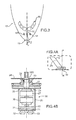
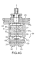
- FIG. 4A An example of an angle measurement probe 35 according to the invention is illustrated in Figures 4A, 4B and 4C .
- the probe comprises a fin 25, mounted to move in rotation on a central axis 24 (of direction AA' in Figure 4A ) of a housing 20 (represented in Figures 4B and 4C ), which is preferably cylindrical.
- the angle ⁇ designates the angle of deflection of the fin, between the leading edge of the fin and the axis 24. The value of this angle is chosen in such a way as to ensure the best trade-off between a minimum stray drag and a maximum sensitivity to low side slips.
- the axis 24 can also move in rotation. It is passive, in as much as it has no function from the electrical point of view (there is neither winding nor power supply about this axis), unlike the known probes.
- the housing 20 is preferably made of a low-contaminant, high-quality thermoplastic material resistant to severe environmental conditions.
- the housing 20 comprises two ends, one situated on the side of the fin 25, and the other situated on the opposite side thereof.
- the housing is closed at both of its ends:
- the fin is not mounted directly on the cover 22, but on a plate 36, called mechanical plate or baseplate, which is in turn fixed to the cover 22.
- the plate 36 is passed through by the axis 24.
- the mounting of the fin on its baseplate 36 is represented in Figure 4A .
- At least one optical encoder for example of the type with multiple disks and multiple barriers.
- mechanical interfaces are provided for fixing the encoder, or encoders, inside the probe. These interfaces enable the encoder, or encoders, to be mounted and removed using screws, accessible from the outside of the probe.
- the housing 20 contains a first and a second optical encoders 26 and 27, mounted on the axis 24.
- Each encoder comprises at least one disk, advantageously two disks.
- Each disk comprises at least one circular track provided with opaque and transparent zones, defining alternate slots, for example 2048 of them, any two neighbouring slots being preferably regularly spaced from each other or being separated by a constant distance.
- a disk structure will be explained in more detail below, notably in conjunction with Figure 6A .
- the disks are preferentially mounted on damping springs or on elements made of an elastic material, which enables them to operate without problems in the event of impacts, vibrations, turbulences, etc.
- the set of two disks is mounted securely, on a lubricated and ingress-protected rolling bearing (recommended for protection index IP 66).
- the internal diameter of the rolling bearing allows it to be mounted on the axis 24.
- Means, for example for a screw fastening, can be provided, on the axis 24 and at the ends of the axis of the rolling bearing, in order to ensure that the axis 24 does not slip inside the rolling bearing of the encoder.
- the encoders are mounted on the axis 24, in such a way that the alignment and the reduction of the radial loads are minimal.
- the axis 24 can include mounting and alignment references.
- the first and the second encoders can be offset by 90° in order to detect a failure on one or other of the encoders.
- the two encoders are mounted at an angle of 45° relative to the axis 24, in such a way as to reduce the effects of a common detection error, due to a single event (for example due to an impact in a determined direction).
- the axis 24 can be fixed by two so-called "load” rolling bearings in such a way that the rolling bearings of the encoders are relieved of any undesirable mechanical effort.
- An advantage of this structure is the reduction of the length of the axis and of the mechanical loads. Compared to the known probes, a reduction of the length of the axis of as much as 40% can be observed.
- Each optical encoder is provided with at least two wired outputs (one for each barrier), with a twisted and shielded conductor cable, so as to ensure a good quality transmission of the signals to the signal processing boards.
- Each optical encoder is advantageously protected in a hermetically-sealed housing (each of the references 26, 27 of Figure 4B designates both an optical encoder and its housing) to avoid any ingress of contaminant.
- the axis 24 passes through each housing through an opening formed in the latter and a seal, for example an O-ring seal, can be provided at the periphery of this opening.
- the probe assembly is assembled in such a way as to offer adequate seal-tightness to water and to fine particules which could otherwise penetrate into each of the housings 20, 26, 27.
- the seals arranged at the input of the device (in the orifice 23) and in the openings of the housings allowing the axis 24 to pass through, contribute to this seal-tightness.
- a probe according to the invention can therefore be doubly seal-tight: in the probe housing and at the individual level of the housing of each optical encoder. This allows for:
- each optical encoder 26, 27, each of them comprising two slotted disks 80, 81 (for the encoder 27) and 82, 83 (for the encoder 26).
- Each disk is fixed to the central axis 24, at right angles thereto.
- each disk is mounted on a dedicated bearing 84 0 , 84 1 , 84 2 , 84 3 , itself also mounted on the axis 24, and its centre is aligned on the axis 24.
- references identical to those of Figures 4A and 4B designate the same elements.
- Each set of two disks can have a geometrical form enabling it to ensure the rigidity and the resistance to significant load factors on the axis Z.
- the housing 20 can contain at least one processing board, advantageously two processing boards 30 and 31, for the processing of the output signals from the optical encoder or encoders. Exemplary embodiments of such a board are given later, in conjunction with Figures 5A and 5B .
- the probe can also be provided with at least one temperature sensor, here two temperature sensors 28 and 29 arranged in the housing 20.
- the latter are incorporated in such a way as to produce a measurement of the temperature of the fin 25 and of its baseplate 36, which is as reliable as possible.
- each of them has an impedance that varies with temperature.
- Each sensor can be produced from a thermistor, but other devices can also be used.
- heating means for the fin 25 and its baseplate 36 can also be provided, as well as a circuit or means for regulating these heating means, on the basis of the data from the temperature sensors 28, 29. Such means and their operation are described later in this text.
- At least one temperature sensor for example a thermo-resistor or a thermopile IR
- a thermo-resistor or a thermopile IR can be provided to give information on the temperature T inside the probe.
- the information concerning the temperature T allows for a correlation between frequent detection errors and an abnormal temperature inside the probe.
- Heating means make it possible to compensate for errors which devolve from the occurrence of thermo-electrical phenomena to which the optical encoders or barriers can be sensitive.
- the housing 20 of the probe forms an EMI (Electromagnetic Interference) shield for all the elements that it contains, and in particular for the processing boards 30 and 31.
- EMI Electromagnetic Interference
- the probe 35 is designed to be fixed on the surface of an aeroplane, the top part of the cover 22 being flush with the skin 34 thereof.
- the fin 25 causes the axis 24 to rotate resulting in the rotation of the disks of the optical encoders 26 and 27.
- the data generated by each encoder are sent to the processing boards 30, 31 and processed by the means with which these boards are provided. Examples of processing of these data generated by each encoder are indicated later.
- Figure 5A is another representation of the probe, and more particularly of the different modules of a processing board 30, 31.
- Each of these boards is interconnected with one of the connectors 32 or 33 of Figures 4B or 4C (but these connectors are not visible in Figure 5A ) and each optical encoder 26, 27 is connected to each processing board 30, 31 which therefore comprises processing means 42-44, 47-49 specific to each optical encoder.
- First processing means 42-44 receive and process the output signals from the first encoder, but not from the second encoder, while second processing means 47-49 receive and process the output signals from the second encoder, but not from the first encoder.
- This Figure 5A also schematically represents the two optical encoders 26 and 27 and the fin 25 of the probe.
- the shielding formed by the housing 20 protects the optical encoders and each processing board 30, 31.
- each processing board 30 or 31 which can be produced in the form of a programmable logic circuit (FPGA, or Field Programmable Gate Array), can comprise, for each optical encoder:
- Interfaces 52, 53 and 54 allow, on the one hand, for the conditioning of the signals transmitted to drivers 60-62, and, on the other hand, for the protection of input ports of each processing board 30, 31 against overvoltages, short-circuits, overcurrents, etc.
- the probe comprises means 38, 39 for heating the fin 25 and its baseplate 36.
- a monitoring and control unit 37 can be dedicated to the control of the heating of these two elements 25, 36, preferably to ensure that they have a temperature T > 0°C.
- This unit 37 can be produced, for example, by using power switching and control devices.
- control of the heating means can be carried out by software.
- Temperature sensors 28, 29 can be provided, arranged as already indicated above.
- probe material a material doped with hydrophobic nanoparticles (in order to prevent water from stagnating on its surface, and ice from forming).
- each processing board 30, 31 can comprise:
- the driver 60, 61 and 62 make it possible to adapt the format of the data to be transmitted to these electronic or computing means; these data are notably angle measurement data, which have been generated by the processing boards 30, 31 as a function of the measurements performed using the optical encoders 26, 27.
- the format of these data is adapted to a format compatible with a transmission by one (or more) determined protocol(s), for example an AFDX, TTP, FiberChanel, ARINC 429 protocol and a CAN (Controller Area Network) bus protocol.
- Means 64 form an interface (for example in the form of a connector) for supplying voltage to the probe, again for example a DC voltage of +28 volts.
- PLC Power Line Current
- the probe of Figure 5A also comprises a DC/DC power converter 63, which supplies the processing board 30, 31 proper, but also the monitoring and control unit 37 of the heating means 38, 39.
- FIG. 5B is a variant embodiment of the probe, with an optical transmission of the data generated by the processing boards 30, 31.
- Each processing board 30 and 31 here comprises two signal conditioning and impedance matching circuits 72, 74. These circuits allow, like the interfaces 52, 53 and 54 of Figure 5A , on the one hand, for the conditioning of the signals to be transmitted to drivers 91, 92, and, on the other hand, for the protection of input ports of the processing board 30, 31 against overvoltages, short-circuits, overcurrents, etc.
- the output from the optical encoders is an electrical signal and short-circuits can occur on the drivers 91, 92 or short-circuits can be provoked by the probe power supply equipment.
- Each of these circuits 72, 74 is therefore connected to the drivers 91, 92 which makes it possible to control optical transceivers and light-emitting diodes (LED).
- An optical contact 93, 94 preferably of expanded beam type, is arranged downstream of each of these means 91, 92.
- Optical fibres 95 preferably of high robustness, then transmit the duly generated optical signal to electronic or computing means, arranged in the aeroplane, downstream of the probe.
- the circuits 72, 74 also control a circuit 97, which in turn controls the interface 64 for supplying voltage to the probe, for example at a DC voltage of +28 volts, from a power line 96.
- the circuit 97 recovers the digital data, from the circuits 72, 74, and processes them according to an OFDM (Orthogonal Frequency Division Modulation) technique.
- This circuit 97 can be produced in the form of a plurality of electronic circuits, such as those used in the field of power line data transmission, by using an OFDM modulation.
- the circuit 97 can notably comprise the following means or circuits:
- All of these functions can be produced in the form of a module which can be integrated in the probe.
- a line coupler can be added to the electrical wiring or connector.
- the cable 96 is preferably a power coaxial cable. This type of cable offers the following advantages:
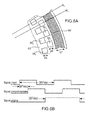
- Figures 6A and 6B respectively represent an optical disk and a timing diagram of the signals that can be generated by it.
- Each disk comprises, preferably, two rows of slots offset in such a way that, on each rotation pitch, a slot and an absence of slot (the direct signal and the complementary signal) can be detected.
- Each disk comprises:
- This offsetting of the slots of the two tracks of one and the same disk makes it possible to identify the direction of rotation of the disk based on the order of arrival of the output electrical signals corresponding to these two tracks 85 and 86.
- Each track of each disk is associated with a photo-electrical barrier.
- Each barrier comprises an LED and a photo-transistor (typically in the infrared range). The latter are arranged in such a way that, when a slot passes in front of the LED, the emitted light is picked up by the photo-transistor.
- Each barrier therefore detects the successions of slots, thus giving electrical signals in phase with the transitions of the slots.
- Each optical barrier is, for example, supplied at low voltage, DC (typically at a voltage of 12 V to 14 V) and supplies a signal in the form of a series of square waves.
- the two barriers of one and the same disk are preferably offset by 180°.
- the tracks of one and the same disk, of one and the same encoder are slightly offset in order to generate an offset of 90° between the period of the signal from the first track (direct signal) and the period of the signal from the second track (complementary signal).
- the electrical signals obtained by the two barriers of one and the same disk are called: direct signal and complementary signal (hereinafter denoted A and A ⁇ ).
- the photo-electrical barrier generating the direct signal is called master photoelectric barrier hereinafter in the description.
- the encoder comprises a second disk
- the electrical signals obtained by the two barriers of this second disk are also called direct signal and complementary signal, and are denoted B and B ⁇ .
- the encoder comprises a second disk
- the two disks are, once again preferably, offset by one slot. This makes it possible to:
- each disk comprises a set of two photo-electrical barriers arranged so that the opening of one of these barriers corresponds to the closure of the other barrier (180° offset already mentioned above) of the disk.
- the direct signal A, B is received before the complementary signal A ⁇ , B ⁇ , and if the direction of rotation of the disk is changed, the complementary signal A ⁇ , B ⁇ is received before the direct signal A, B.
- the direction of rotation of the disk of the encoder is thus known.
- the disk OE1-D1 of the encoder OE1 comprises two photo-electrical barriers (or two data channels), designated OE1-D1-A1 (generating a direct signal A1) and OE1-D1-A1 ⁇ (generating a complementary signal A1 ⁇ ). These photo-electrical barriers OE1-D1-A1 and OE1-D1-A1 ⁇ are offset, relative to one another, by 180°.
- the disk OE1-D2 of OE1 comprises two photo-electrical barriers (or two data channels), designated OE1-D2-B1 (generating a direct signal B1) and OE1-D2-B1 ⁇ (generating a complementary signal B1 ⁇ ). These photo-electrical barriers OE1-D2-B1 and OE1-D2-B1 ⁇ are offset, relative to one another, by 180°.
- OE2 is used to designate the other optical encoder, also provided with two disks D1 and D2 (denoted OE2-D1 and OE2-D2).
- the disk OE2-D1 of OE2 comprises two photo-electrical barriers (or two data channels), designated OE2-D1-A2 (generating a direct signal A2) and OE2-D1-A2 ⁇ (generating a complementary signal A2 ⁇ ). These photo-electrical barriers OE2-D1-A2 and OE2-D1-A2 ⁇ are offset, relative to one another, by 180°.
- the disk OE2-D2 of OE2 comprises two photo-electrical barriers (or two data channels), designated OE2-D2-B2 (generating a direct signal B2) and OE2-D2-B2 ⁇ (generating a complementary signal B2 ⁇ ). These photo-electrical barriers OE2-D2-B2 and OE2-D2-B2 ⁇ are offset, relative to one another, by 180°.
- the photo-electrical barriers are arranged to make it possible to work in a number of modes:
- Figure 6B illustrates the order of arrival of the signals from a disk, and, more particularly, an offset between the signal from the first track (direct signal) and the signal from the second track (complementary signal).
- the offset is 90° in the period.
- each optical encoder 26 and 27 has at least one disk, advantageously two disks (OE1-D1 and OE1-D2) provided with two tracks with transparent slots, each of the tracks associated with a photo-electrical barrier (A and B). Because of its structure, each disk of an optical encoder, for example OE1-D1, supplies the following signals:
- Each of the processing means 42-44, 46-49 associated with each optical encoder receives the direct signals and the complementary signals from this optical encoder.
- the corresponding processing means then work out the processing of these data, to determine the direction of rotation of the fin and the angle of this rotation:
- the direction of rotation of the assembly is determined from the analysis of the signals from each disk which makes it possible to determine the direction of rotation of the disks, obtained by detecting which signal from which track is received first: direct or complementary.
- direct or complementary In relation to Figure 6B , if the direct signal is measured before the complementary signal, the disk is rotating in one direction; if the complementary signal is received before the direct signal, the disk is rotating in the other direction.
- each of the direct signals from each of the disks is measured before each of the associated complementary signals, all the direct signals are measured before the associated complementary signals.
- a difference in the order of measurement of the signals from a disk in relation to the other disks indicates a failure of the assembly, for example a disk which has become detached from the axis 24.
- the measurement of the angle is obtained by counting the number of signal pulses (direct or complementary), because each pulse corresponds to a detection of the passage of a slot facing the opto-electronic barrier. If there are two encoders in the probe, there is twice the accuracy.
- the data determined by the processing means as explained above are then conditioned in a bus frame and transmitted to the onboard data processing computers.
- a bus frame can comprise data such as:
- each optical encoder can send all the signals, outgoing in the form of pulses, to each of the processing boards, which can receive and process all the signals at a modest cost, because all the data are digital. All that is needed is to count the pulses of the signals and convert them into angles.
- the software processing part of the probes incorporates a set of functions which make it possible to manage these probes according to their operating context.
Landscapes
- Physics & Mathematics (AREA)
- General Physics & Mathematics (AREA)
- Engineering & Computer Science (AREA)
- Aviation & Aerospace Engineering (AREA)
- Optical Transform (AREA)
Abstract
Description
- The invention relates to an angle measurement probe on board an aircraft, for example for measuring the angle of attack or the side slip angle, and an aircraft implementing at least one such probe.
- Hereinbelow, an aircraft of aeroplane type will be considered by way of example.
- The data systems on board an aircraft, such as an aeroplane, comprise aerodynamic and thermodynamic sensors and their associated electronics which measure the characteristics of the air stream surrounding the aeroplane and convert this information into electrical signals. These sensors comprise transducers, rotating electrical machines, or, more generally, resolvers, or pressure difference devices, the signals of which are processed to obtain flight parameters such as the angle of attack and the side slip angle.
- These sensors are situated at specific points of the cockpit of the aeroplane. They are in particular temperature sensors, rotating fins or multifunction devices incorporating probes of tube type ("tube-slot") with self-alignment capabilities.
- Such instrumentation exhibits drawbacks such as a sensitivity to electromagnetic threats, heavy weight, a relatively large volume, a need for several power supply voltages, etc. Furthermore, the high accuracy of certain sensors can lead to high costs, and condition the technology to be employed and the positioning of these sensors.
- In the aeroplanes, the data originating from the onboard sensors make it possible to provide information to the pilot. Some of these data relate to particular measurements, which are those of the angle of attack and the side slip angle. Currently, these measurements are performed using specific rotating electrical machines.
- The angle of attack is an angle measured in the normally vertical plane X-Z of symmetry of an aeroplane. More specifically, this angle is measured relative to a reference line, which is a line linking the leading edge and the trailing edge at median points on a wing. Most commercial aeroplanes use the central line or the longitudinal axis of the fuselage as reference line. The angle of attack is defined as the angle at which the relative wind encounters the reference line of the wing or of the fuselage.
- The side slip angle is the angle between a vector, called aeroplane speed vector, and the longitudinal axis thereof.
- To measure the angle of attack and the side slip angle of an aeroplane, there are in particular known:
- a measurement method based on probes using fins that can move in rotation,
- a measurement method based on probes using pitot tubes and/or holed surfaces and/or tubes.
- A
probe 16 using a fin that can move in rotation is represented inFigures 1A to 1C and 2 . With such a probe, it is possible to measure the angle of attack as follows. Afin 10 is oriented in the direction of the local air stream, parallel to the relative wind of the apparatus. Electronic means make it possible to determine the angle between the local air stream and a reference axis of the aeroplane, in order to then estimate, by difference, the angle of attack. The fin is mounted to move in rotation on acentral axis 14 of acylindrical housing 11. The latter is closed at both of its ends, and is also provided, on the one hand, with aconnector 13 and, on the other hand, with aplate 12 pierced with a central circular orifice which is passed through by theaxis 14. - A measurement method based on the use of this type of device is commonly used to measure the angle of attack and the side slip angle. The measurement of these angles makes it possible to know if the aeroplane is within the flight envelope limits specified by the aeroplane manufacturer.
- The
fin 10 illustrated inFigures 1A to 1C can revolve freely by a given angle, so as to be positioned in a local air flow in line with the probe and parallel thereto. - The rotation of the fin is transmitted to the
axis 14, on which it is mounted, and which is in turn coupled to a rotary position transducer 15 with brushless resolver. The electrical signal generated by the latter can then be processed by a processing circuit and be converted into a digital signal, which can be transmitted to the onboard computer via a data bus. - Such a probe with rotating fin from the known art can also use an actively controlled slot heating technology, in order to de-ice the fin in all icing conditions.
- The document
FR 2922301 US 2009 099811 ) describes the use of such a probe which, as illustrated inFigure 3 , is positioned on the surface of the fuselage of anaeroplane 17, in the front part thereof, precisely in the region situated in front of the cockpit 18 (the term "front" being understood in the conventional manner, that is to say towards thenose 19 of the aeroplane, in the direction X). The measured side slip angle β is thus the angle formed locally between the orientation of the speed vector of the flow of the air in line with the probeV and the direction X projected in a horizontal plane. Other side slip probes can be provided on the surface of the fuselage of the aeroplane, such as, for example,probes 16', 16". - Such a probe with rotating fin from the known art presents the following drawbacks:
- its volume is large and can lead to integration difficulties because of the reduced space available,
- its weight is heavy: approximately 1925 kg per probe.
- The subject of the invention is an angle measurement probe on board an aircraft, for example an aeroplane, that makes it possible to provide a digital signal whose value is a function of a side slip angle or of an angle of attack of this aircraft while attempting to mitigate the various drawbacks defined above.
- The invention also aims to propose a novel type of probe with rotating fin, which makes it possible to solve one or more of the abovementioned problems.
- According to one of its aspects, the invention relates to an angle measurement probe on board an aircraft, for example for measuring an angle of attack or a side slip angle, which comprises:
- a fin, which can move in rotation about an axis,
- at least one first optical encoder and one second optical encoder, each comprising at least one disk, each disk being fixed at right angles to the central axis and being provided with at least two circular tracks, each track being provided with alternate opaque zones and transparent slots (two adjacent slots - or any two adjacent slots - of one track being possibly regularly spaced from each other and/or separated by an opaque zone),
- means for processing the output signal from each encoder.
- The probe can comprise a housing which contains the optical encoder(s) and the means for processing the output signal from each encoder.
- Preferentially, the housing and each encoder are seal-tight.
- In a particular embodiment, the probe also comprises optical transmission means for transmitting angle data generated by the means for processing the output signal from each encoder.
- Preferentially, the probe also comprises:
- at least one temperature sensor sensing the temperature of the fin,
- means for heating the fin on the basis of data measured by said temperature sensor sensing the temperature of the fin.
- Damping means for each disk can also be provided.
- Each optical encoder can comprise two disks, each track of each disk being associated with an opto-electrical barrier which generates a signal, one of which is called direct signal and the other of which is called complementary signal.
- In such a probe, the two disks of one and the same encoder are preferentially offset by 90°, in order to be able to check the robustness of the installation and the quality of the information.
- In such a probe, the two tracks of one and the same disk can be offset in order to generate an offset of 90° between the period of the signal from one of the two tracks and the period of the signal from the other track.
- Preferentially, the signal processing means determine the direction of rotation of the fin and its angle of rotation as a function of at least two signals, each of these two signals being associated with a track of one of the disks.
- A check on the data can be performed, in which:
- a) if all the data computed for the different optical encoders are identical, the data generated for one of them are selected;
- b) if the data generated for one of the encoders are different from those generated for the other encoder or encoders, a check is performed over several measurement cycles for confirmation, and the data which are different from those obtained for all the other encoders are eliminated.
- A probe according to the invention preferentially comprises first processing means, which receive and process the output signals from the first encoder, but not from the second encoder, and second processing means, which receive and process the output signals from the second encoder, but not from the first encoder.
- In a particular embodiment, the processing means store a plurality of results relating to the direction and the angle of rotation, for:
- performing at least one comparison between the data;
- and/or checking the consistency of the measured data;
- and/or eliminating anomalies;
- and/or retransmitting data lost in a transmission of said data;
- and/or ensuring a transition between a double-accuracy measurement mode and a single-accuracy measurement mode.
- According to one embodiment, each disk comprises at least two concentric tracks, each comprising successive slots, aligned in a circle centred on the centre of the disk, the slots of each track being offset relative to the slots of each other track.
- Preferentially, the two barriers of one and the same disk are offset by 180°.
- An aircraft can comprise at least one probe as described hereinabove, it can also comprise a plurality, for example two or three, of these probes.
- The probe according to the invention offers numerous advantages:
- it makes it possible to detect a physical phenomenon (air stream) by using a method that is different and advantageous compared to the methods implemented in the prior art,
- it makes it possible to implement and use advantageously a plurality of technologies,
- it allows for operation in single-accuracy or double-accuracy mode (double encoder, double channel with redundant architecture),
- it does not require a very fine alignment, unlike the known solutions: it is sufficient for the axis to transmit a rotation movement, the only alignment being that of the axial reference of the encoder with the axis of the fin.
-
-
Figures 1A to 1C and 2 illustrate an angle measurement probe of the known art respectively in a plan view, in two side views and in a longitudinal cross section. -
Figure 3 illustrates the front part of an aeroplane incorporating such a probe from the known art. -
Figures 4A-4C illustrates aspects of an angle measurement probe according to the invention. -
Figure 5A illustrates the circuits of each of the processing boards of the probe according to the invention,Figure 5B illustrating a variant embodiment. -
Figure 6A illustrates a view of a part of a disk of an optical encoder of the probe according to the invention. -
Figure 6B represents signals from the two tracks of one and the same disk illustrating the direction of rotation of an optical encoder of the probe according to the invention. - An example of an
angle measurement probe 35 according to the invention is illustrated inFigures 4A, 4B and4C . - In this example, the probe comprises a
fin 25, mounted to move in rotation on a central axis 24 (of direction AA' inFigure 4A ) of a housing 20 (represented inFigures 4B and4C ), which is preferably cylindrical. The angle α designates the angle of deflection of the fin, between the leading edge of the fin and theaxis 24. The value of this angle is chosen in such a way as to ensure the best trade-off between a minimum stray drag and a maximum sensitivity to low side slips. Theaxis 24 can also move in rotation. It is passive, in as much as it has no function from the electrical point of view (there is neither winding nor power supply about this axis), unlike the known probes. - The
housing 20 is preferably made of a low-contaminant, high-quality thermoplastic material resistant to severe environmental conditions. - The
housing 20 comprises two ends, one situated on the side of thefin 25, and the other situated on the opposite side thereof. The housing is closed at both of its ends: - on the fin side, by a
cover 22, which is pierced with anorifice 23, preferably circular and arranged in the middle or at the centre of the cover. This orifice allows for the passage of theaxis 24, about which a seal 240 can be arranged; - on the side opposite the fin, by a bottom 21, on the outer surface of which is fixed at least one, or more, connectors, here two
connectors - The fin is not mounted directly on the
cover 22, but on aplate 36, called mechanical plate or baseplate, which is in turn fixed to thecover 22. Theplate 36 is passed through by theaxis 24. The mounting of the fin on itsbaseplate 36 is represented inFigure 4A . - In the
housing 20, there is arranged at least one optical encoder, for example of the type with multiple disks and multiple barriers. - To this end, mechanical interfaces are provided for fixing the encoder, or encoders, inside the probe. These interfaces enable the encoder, or encoders, to be mounted and removed using screws, accessible from the outside of the probe.
- In the example illustrated, the
housing 20 contains a first and a secondoptical encoders axis 24. Each encoder comprises at least one disk, advantageously two disks. Each disk comprises at least one circular track provided with opaque and transparent zones, defining alternate slots, for example 2048 of them, any two neighbouring slots being preferably regularly spaced from each other or being separated by a constant distance. A disk structure will be explained in more detail below, notably in conjunction withFigure 6A . The disks are preferentially mounted on damping springs or on elements made of an elastic material, which enables them to operate without problems in the event of impacts, vibrations, turbulences, etc. - The set of two disks is mounted securely, on a lubricated and ingress-protected rolling bearing (recommended for protection index IP 66). The internal diameter of the rolling bearing allows it to be mounted on the
axis 24. Means, for example for a screw fastening, can be provided, on theaxis 24 and at the ends of the axis of the rolling bearing, in order to ensure that theaxis 24 does not slip inside the rolling bearing of the encoder. - The encoders are mounted on the
axis 24, in such a way that the alignment and the reduction of the radial loads are minimal. To this end, theaxis 24 can include mounting and alignment references. - The first and the second encoders can be offset by 90° in order to detect a failure on one or other of the encoders.
- Optionally, the two encoders are mounted at an angle of 45° relative to the
axis 24, in such a way as to reduce the effects of a common detection error, due to a single event (for example due to an impact in a determined direction). - The
axis 24 can be fixed by two so-called "load" rolling bearings in such a way that the rolling bearings of the encoders are relieved of any undesirable mechanical effort. - An advantage of this structure is the reduction of the length of the axis and of the mechanical loads. Compared to the known probes, a reduction of the length of the axis of as much as 40% can be observed.
- Each optical encoder is provided with at least two wired outputs (one for each barrier), with a twisted and shielded conductor cable, so as to ensure a good quality transmission of the signals to the signal processing boards.
- Each optical encoder is advantageously protected in a hermetically-sealed housing (each of the
references Figure 4B designates both an optical encoder and its housing) to avoid any ingress of contaminant. Theaxis 24 passes through each housing through an opening formed in the latter and a seal, for example an O-ring seal, can be provided at the periphery of this opening. - The probe assembly is assembled in such a way as to offer adequate seal-tightness to water and to fine particules which could otherwise penetrate into each of the
housings axis 24 to pass through, contribute to this seal-tightness. - A probe according to the invention can therefore be doubly seal-tight: in the probe housing and at the individual level of the housing of each optical encoder. This allows for:
- operation in a degraded context, for example after the impact of a bird on the cockpit of the aeroplane,
- the maintenance of one of the optical encoders without intervention on another of these encoders.
- In
Figure 4C , the encoders are represented without their respective housing. - This figure therefore shows in more detail the construction of each
optical encoder disks 80, 81 (for the encoder 27) and 82, 83 (for the encoder 26). Each disk is fixed to thecentral axis 24, at right angles thereto. - More specifically, each disk is mounted on a dedicated bearing 840, 841, 842, 843, itself also mounted on the
axis 24, and its centre is aligned on theaxis 24. In thisFigure 4C , references identical to those ofFigures 4A and 4B designate the same elements. - Each set of two disks can have a geometrical form enabling it to ensure the rigidity and the resistance to significant load factors on the axis Z.
- As represented in
Figures 4B and4C , thehousing 20 can contain at least one processing board, advantageously twoprocessing boards Figures 5A and5B . - The probe can also be provided with at least one temperature sensor, here two
temperature sensors housing 20. Preferably, the latter are incorporated in such a way as to produce a measurement of the temperature of thefin 25 and of itsbaseplate 36, which is as reliable as possible. Typically, each of them has an impedance that varies with temperature. Each sensor can be produced from a thermistor, but other devices can also be used. Advantageously, heating means for thefin 25 and itsbaseplate 36 can also be provided, as well as a circuit or means for regulating these heating means, on the basis of the data from thetemperature sensors - Moreover, at least one temperature sensor (for example a thermo-resistor or a thermopile IR) can be provided to give information on the temperature T inside the probe. The information concerning the temperature T allows for a correlation between frequent detection errors and an abnormal temperature inside the probe. Heating means make it possible to compensate for errors which devolve from the occurrence of thermo-electrical phenomena to which the optical encoders or barriers can be sensitive.
- These various heating means and means for regulating these heating means are not represented in
Figures 4A and 4B , but schematically represented inFigures 5A and5B . - The
housing 20 of the probe forms an EMI (Electromagnetic Interference) shield for all the elements that it contains, and in particular for theprocessing boards - The
probe 35 is designed to be fixed on the surface of an aeroplane, the top part of thecover 22 being flush with theskin 34 thereof. - When the aeroplane changes altitude (change of the value of the pitch angle or of the yaw angle), the
fin 25 causes theaxis 24 to rotate resulting in the rotation of the disks of theoptical encoders processing boards -
Figure 5A is another representation of the probe, and more particularly of the different modules of aprocessing board connectors Figures 4B or4C (but these connectors are not visible inFigure 5A ) and eachoptical encoder board - This
Figure 5A also schematically represents the twooptical encoders fin 25 of the probe. The shielding formed by thehousing 20 protects the optical encoders and each processingboard - In more detail, each processing
board - an input/
output interface - a
logic processing unit - a
memory unit - means 51, 45, 50 which implement synchronization functions for the internal buses, notably a clock function and a function for checking the contained tasks and processes (watchdog),
- buffer-forming
means 56 for managing the data queues. - These different functions can be implemented in the form of a single programmable integrated circuit (of FPGA, Field Programmable Gate Array, type).
-
Interfaces board - From the thermal point of view, the probe comprises means 38, 39 for heating the
fin 25 and itsbaseplate 36. A monitoring andcontrol unit 37 can be dedicated to the control of the heating of these twoelements unit 37 can be produced, for example, by using power switching and control devices. As a variant, control of the heating means can be carried out by software.Temperature sensors - In conjunction with this heating and de-icing aspect, it is also possible to use, as probe material, a material doped with hydrophobic nanoparticles (in order to prevent water from stagnating on its surface, and ice from forming).
- Moreover, each processing
board - an input/
output interface 40 for the data from thetemperature sensors - a
circuit 41 for processing these data, which will generate signals for controlling the monitoring andcontrol unit 37 of the heating means 38, 39. - For compatibility with electronic or computing means, arranged in the aeroplane, downstream of the probe, the
driver processing boards optical encoders - The probe of
Figure 5A also comprises a DC/DC power converter 63, which supplies theprocessing board control unit 37 of the heating means 38, 39. -
Figure 5B is a variant embodiment of the probe, with an optical transmission of the data generated by theprocessing boards Figure 5A will not be described again here. Each processingboard impedance matching circuits interfaces Figure 5A , on the one hand, for the conditioning of the signals to be transmitted todrivers processing board drivers - Each of these
circuits drivers optical contact means -
Optical fibres 95, preferably of high robustness, then transmit the duly generated optical signal to electronic or computing means, arranged in the aeroplane, downstream of the probe. - The
circuits circuit 97, which in turn controls theinterface 64 for supplying voltage to the probe, for example at a DC voltage of +28 volts, from apower line 96. - More particularly, the
circuit 97 recovers the digital data, from thecircuits circuit 97 can be produced in the form of a plurality of electronic circuits, such as those used in the field of power line data transmission, by using an OFDM modulation. Thecircuit 97 can notably comprise the following means or circuits: - o means, or a circuit, of scrambler type, which make it possible to change the probability of long sequences of "0" and of "1" bits (for error correction);
- o means, or a circuit, forming a cyclic encoder, in order to insert bits into the frames for the error detecting and correcting codes;
- o means, or a circuit, forming an interleaver for protection against errors (burst errors) originating from the errored writing of bits in a queue;
- o mapping means, or a mapping circuit, for mapping, for each subcarrier, the data bits with a view to modulation;
- ○ a Fourier transform inverter, which makes it possible to decompose a series of values into components of different frequencies;
- ○ an A/D converter, which makes it possible to convert the digital data into analogue signals;
- ○ an output amplifier (for the line output).
- All of these functions can be produced in the form of a module which can be integrated in the probe.
- A line coupler can be added to the electrical wiring or connector.
- To produce this circuit, it is possible, for example, to use the circuit MAX2990 from MAXIM.
- The
cable 96 is preferably a power coaxial cable. This type of cable offers the following advantages: - it exhibits a high electromagnetic immunity;
- it provides good protection for data transmission;
- it is simple and quick to connect (all that is needed is a connector of bayonet type - like the BNC or TNC connectors);
- it makes it possible to place the optical fibres and the power cable in a single bundle (in a single loom);
- if a point of attachment is lost in a composite environment, no current is injected into the skin of the aeroplane, because the ground braid is on the outside.
-
Figures 6A and 6B respectively represent an optical disk and a timing diagram of the signals that can be generated by it. - Each disk comprises, preferably, two rows of slots offset in such a way that, on each rotation pitch, a slot and an absence of slot (the direct signal and the complementary signal) can be detected.
- More specifically, an exemplary embodiment of a part of one of the
optical disks Figure 6A . Each disk comprises: - a
measurement track 87, which comprises for example 2048; this track makes it possible to generate an origin signal; - and two concentric
complementary tracks adjacent slots 851, 852 (respectively 861, 862) of one track being separated by an opaque zone 85' (respectively 86'). The slots, and the opaque zones which separate adjacent slots, of one of the two tracks are of dimensions substantially identical to those of the other track. The series of slots of one of the tracks is offset relative to the series of the slots of the other track; in a given radial direction R1 (respectively R2) of the disk, there is first of all a slot (respectively: an opaque zone between two slots) of thefirst track 85, the innermost of the disk, then an opaque zone between two slots (respectively: a slot) of thesecond track 86, situated between the first track and themeasurement track 87. - This offsetting of the slots of the two tracks of one and the same disk makes it possible to identify the direction of rotation of the disk based on the order of arrival of the output electrical signals corresponding to these two
tracks - Each track of each disk is associated with a photo-electrical barrier. Each barrier comprises an LED and a photo-transistor (typically in the infrared range). The latter are arranged in such a way that, when a slot passes in front of the LED, the emitted light is picked up by the photo-transistor. Each barrier therefore detects the successions of slots, thus giving electrical signals in phase with the transitions of the slots. Each optical barrier is, for example, supplied at low voltage, DC (typically at a voltage of 12 V to 14 V) and supplies a signal in the form of a series of square waves.
- The two barriers of one and the same disk are preferably offset by 180°.
- For their part, the tracks of one and the same disk, of one and the same encoder, are slightly offset in order to generate an offset of 90° between the period of the signal from the first track (direct signal) and the period of the signal from the second track (complementary signal).
- These offsets make it possible to reduce the interpolation errors in the processing of the signals, performed in the electronic boards already described above.
- The electrical signals obtained by the two barriers of one and the same disk are called: direct signal and complementary signal (hereinafter denoted A and A\). The photo-electrical barrier generating the direct signal is called master photoelectric barrier hereinafter in the description.
- If the encoder comprises a second disk, the electrical signals obtained by the two barriers of this second disk are also called direct signal and complementary signal, and are denoted B and B\.
- Also in the case where the encoder comprises a second disk, the two disks are, once again preferably, offset by one slot. This makes it possible to:
- double the accuracy of the detection for a given number of slots;
- detect the direction of rotation both at the disk level and also at the decoder level;
- work in double-accuracy or single-accuracy mode (if one of the barriers fails).
- As will be understood from the above explanations, each disk comprises a set of two photo-electrical barriers arranged so that the opening of one of these barriers corresponds to the closure of the other barrier (180° offset already mentioned above) of the disk.
- Thus, if the disk of an encoder is rotated in one direction, the direct signal A, B is received before the complementary signal A\, B\, and if the direction of rotation of the disk is changed, the complementary signal A\, B\ is received before the direct signal A, B. The direction of rotation of the disk of the encoder is thus known.
- In the case of a device comprising two encoders, each with two disks, the following notations can be chosen:
- OE1 is used to designate one of the optical encoders, provided with two disks D1 and D2 (denoted OE1-D1 and OE1-D2).
- The disk OE1-D1 of the encoder OE1 comprises two photo-electrical barriers (or two data channels), designated OE1-D1-A1 (generating a direct signal A1) and OE1-D1-A1\ (generating a complementary signal A1\). These photo-electrical barriers OE1-D1-A1 and OE1-D1-A1\ are offset, relative to one another, by 180°.
- The disk OE1-D2 of OE1 comprises two photo-electrical barriers (or two data channels), designated OE1-D2-B1 (generating a direct signal B1) and OE1-D2-B1\ (generating a complementary signal B1\). These photo-electrical barriers OE1-D2-B1 and OE1-D2-B1\ are offset, relative to one another, by 180°.
- OE2 is used to designate the other optical encoder, also provided with two disks D1 and D2 (denoted OE2-D1 and OE2-D2).
- The disk OE2-D1 of OE2 comprises two photo-electrical barriers (or two data channels), designated OE2-D1-A2 (generating a direct signal A2) and OE2-D1-A2\ (generating a complementary signal A2\). These photo-electrical barriers OE2-D1-A2 and OE2-D1-A2\ are offset, relative to one another, by 180°.
- The disk OE2-D2 of OE2 comprises two photo-electrical barriers (or two data channels), designated OE2-D2-B2 (generating a direct signal B2) and OE2-D2-B2\ (generating a complementary signal B2\). These photo-electrical barriers OE2-D2-B2 and OE2-D2-B2\ are offset, relative to one another, by 180°.
- The photo-electrical barriers are arranged to make it possible to work in a number of modes:
- double-accuracy mode: the signals from both channels are available: there are, for example, 4096 slots per revolution, or
- single-accuracy mode: just one channel is available: there are, for example, 2048 slots per revolution,
- failure mode: if one of the two
encoders -
Figure 6B illustrates the order of arrival of the signals from a disk, and, more particularly, an offset between the signal from the first track (direct signal) and the signal from the second track (complementary signal). The offset is 90° in the period. - As already explained above, each
optical encoder 26 and 27 (or OE1 and OE2) has at least one disk, advantageously two disks (OE1-D1 and OE1-D2) provided with two tracks with transparent slots, each of the tracks associated with a photo-electrical barrier (A and B). Because of its structure, each disk of an optical encoder, for example OE1-D1, supplies the following signals: - a direct signal: OE1-D1-A1;
- a complementary signal: OE1-D1-A1\;
- an origin signal 0. This is, for example, generated as explained above, using a measurement track such as the
track 87. - If a second disk is used in this same optical encoder OE1, it supplies the following signals:
- a direct signal: OE1-D2-B1;
- a complementary signal: OE1-D2-B1\;
- an origin signal: 0.
- Each of the processing means 42-44, 46-49 associated with each optical encoder receives the direct signals and the complementary signals from this optical encoder.
- The corresponding processing means then work out the processing of these data, to determine the direction of rotation of the fin and the angle of this rotation:
- a) if all the data computed by the different processing means 42-44, 47-49, associated with the different optical encoders, are identical, the data generated by one of these processing means are selected (this processing means is then called the "master");
- b) if the data generated by one of the processing means are different from those generated by the other processing means, a check is performed over a number of measurement cycles for confirmation, and the data which are different from those obtained by all the other processing means are eliminated. If there are only two processing means, the value returned by each of the two systems is compared with the distribution of the stored values, and the one which has the greatest probability of being in the distribution is retained.
- Since the disks and the encoders are mounted on the
axis 24, they rotate in the same direction of rotation. The direction of rotation of the assembly is determined from the analysis of the signals from each disk which makes it possible to determine the direction of rotation of the disks, obtained by detecting which signal from which track is received first: direct or complementary. In relation toFigure 6B , if the direct signal is measured before the complementary signal, the disk is rotating in one direction; if the complementary signal is received before the direct signal, the disk is rotating in the other direction. When there is no failure of the assembly, each of the direct signals from each of the disks is measured before each of the associated complementary signals, all the direct signals are measured before the associated complementary signals. A difference in the order of measurement of the signals from a disk in relation to the other disks indicates a failure of the assembly, for example a disk which has become detached from theaxis 24. The measurement of the angle is obtained by counting the number of signal pulses (direct or complementary), because each pulse corresponds to a detection of the passage of a slot facing the opto-electronic barrier. If there are two encoders in the probe, there is twice the accuracy. - Each of the processing means 42-44, 47-49, associated with each optical encoder, stores the results of the last x estimations of the direction and of the angle of rotation (for example x=16, 32, 64 or 128).
- These estimations are used in the electronic processing algorithms to:
- perform the comparison between the data generated by the different processing means;
- and/or check the consistency of the measurements (continuity in the measurements taken);
- and/or eliminate anomalies;
- optionally, retransmit frames lost in the transmission protocol;
- and/or ensure a consistent transition from the double-accuracy measurement mode to the single-accuracy measurement mode.
- The data determined by the processing means as explained above are then conditioned in a bus frame and transmitted to the onboard data processing computers.
- A bus frame can comprise data such as:
- identity of the probe,
- identity of the current master photo-electrical barrier,
- direct identity of the master optical encoder and complementary identity of the processing means which has performed the measurement,
- results of the current estimation and of the last x measurements,
- frame consistency verification code.
- As will be understood from the explanations which have already been given above, the processing electronics can be redundant, if two
processing boards - The software processing part of the probes incorporates a set of functions which make it possible to manage these probes according to their operating context.
- It is thus possible to make use of a state machine (used in the programming algorithm) operating on the principle of a cellular automaton in order to increase the availability of the aeroplane, for example to:
- enable operation of the probe when one of the two temperature sensors has failed,
- enable operation if both temperature sensors have failed,
- enable operation if an encoder channel has failed,
- enable operation if one encoder has failed,
- enable operation if two channels of two different encoders have failed, and so on.
Claims (15)
- Angle measurement probe on board an aircraft, comprising:- a fin (25), which can move in rotation about an axis (24),- at least one first optical encoder (26) and one second optical encoder (27), each comprising at least one disk (80-83), each disk being fixed at right angles to the central axis (24) and being provided with at least two circular tracks (87), each track being provided with transparent slots alternating with opaque zones, each disk (80, 81, 82, 83) comprising at least two concentric tracks, each comprising successive slots (851, 852, 861, 862), the slots of each track being offset relative to the slots of each other track,- means (30, 31) for processing the output signal from each encoder.
- Probe according to Claim 1, also comprising a housing (20) which contains said optical encoder(s) (26, 27) and the means (30, 31) for processing the output signal from each encoder.
- Probe according to Claim 2, the housing and each encoder being seal-tight.
- Probe according to one of Claims 1 to 3, also comprising optical transmission means (93-95) for transmitting angle measurement data generated by the means (30, 31) for processing the output signal from each encoder.
- Probe according to one of Claims 1 to 4, also comprising:- at least one temperature sensor (28, 29) sensing the temperature of the fin (25),- means (37, 38, 40, 41) for heating the fin (25) on the basis of data measured by said temperature sensor (28, 29) sensing the temperature of the fin (25).
- Probe according to one of Claims 1 to 5, also comprising damping means for each disk.
- Probe according to one of Claims 1 to 6, in which each optical encoder comprises two disks, each track of each disk being associated with an opto-electrical barrier which generates a signal, one of which is called direct signal and the other of which is called complementary signal.
- Probe according to Claim 7, in which the two disks of one and the same encoder are offset by 90°.
- Probe according to one of Claims 1 to 8, in which the two tracks of one and the same disk are offset in order to generate an offset of 90° between the period of the signal from one of the two tracks and the period of the signal from the other track.
- Probe according to one of Claims 1 to 9, in which said signal processing means (30, 31) determine the direction of rotation of the fin and its angle of rotation as a function of at least two signals, each of these two signals being associated with a track of one of the disks.
- Probe according to Claim 10, in which:a) if all the data computed for the different optical encoders are identical, the data generated for one of them are selected;b) if the data generated for one of the encoders are different from those generated for the other encoder or encoders, a check is performed over several measurement cycles for confirmation, and the data which are different from those obtained for all the other encoders are eliminated.
- Probe according to one of Claims 10 or 11, comprising first processing means (42-44) which receive and process the output signals from the first encoder, but not from the second encoder, and second processing means (47-49) which receive and process the output signals from the second encoder, but not from the first encoder.
- Probe according to one of Claims 1 to 12, in which the processing means store a plurality of results relating to the direction and the angle of rotation, for:- performing at least one comparison between the data;- and/or checking the consistency of the measured data;- and/or eliminating anomalies;- and/or retransmitting data lost in a transmission of said data;- and/or ensuring a transition between a double-accuracy measurement mode and a single-accuracy measurement mode.
- Probe according to one of Claims 1 to 13, in which the two barriers of one and the same disk are offset by 180°.
- Aircraft comprising at least one probe according to any one of the preceding claims arranged on the skin thereof.
Applications Claiming Priority (1)
| Application Number | Priority Date | Filing Date | Title |
|---|---|---|---|
| FR1351437A FR3002320B1 (en) | 2013-02-20 | 2013-02-20 | ANGULAR MEASUREMENT PROBE ABOARD AN AIRCRAFT AND AIRCRAFT EMPLOYING AT LEAST ONE SUCH PROBE |
Publications (2)
| Publication Number | Publication Date |
|---|---|
| EP2770330A1 true EP2770330A1 (en) | 2014-08-27 |
| EP2770330B1 EP2770330B1 (en) | 2021-04-14 |
Family
ID=48771581
Family Applications (1)
| Application Number | Title | Priority Date | Filing Date |
|---|---|---|---|
| EP14155519.3A Active EP2770330B1 (en) | 2013-02-20 | 2014-02-18 | Angle measurement probe on board an aircraft and aircraft implementing at least one such probe |
Country Status (4)
| Country | Link |
|---|---|
| US (1) | US9233760B2 (en) |
| EP (1) | EP2770330B1 (en) |
| CN (1) | CN104006766A (en) |
| FR (1) | FR3002320B1 (en) |
Families Citing this family (18)
| Publication number | Priority date | Publication date | Assignee | Title |
|---|---|---|---|---|
| FR3012222B1 (en) * | 2013-10-22 | 2019-08-02 | Arianegroup Sas | METHOD AND DEVICE FOR MEASURING THE IMPACT OF AN AIRCRAFT |
| EP2998817B1 (en) * | 2014-09-16 | 2017-06-07 | Aviovision | System for calculating aircraft performance and method for performing the same |
| US9703293B2 (en) * | 2015-08-31 | 2017-07-11 | The Boeing Company | Aircraft stall protection system |
| US10160548B2 (en) * | 2016-01-04 | 2018-12-25 | The Boeing Company | Apparatuses and methods for anti-icing of speed measurement probes |
| US10296013B2 (en) * | 2016-05-16 | 2019-05-21 | Booz Allen Hamilton Inc. | Vehicle guidance system and method that uses air data from surface-mounted pressure sensors for vehicle orientation control |
| US10457412B2 (en) * | 2016-09-16 | 2019-10-29 | Rosemount Aerospace Inc. | Electrical isolation of angle of attack vane bearings |
| WO2018081559A1 (en) * | 2016-10-27 | 2018-05-03 | Ohio University | Air data probe |
| CN107238366B (en) * | 2017-05-26 | 2023-02-28 | 成都凯天电子股份有限公司 | Wind vane angle of attack airspeed sensor protection device |
| JP2019113428A (en) * | 2017-12-25 | 2019-07-11 | 東日本旅客鉄道株式会社 | Wind direction measuring apparatus |
| JP7193635B2 (en) | 2018-12-06 | 2022-12-20 | 株式会社ハーモニック・ドライブ・システムズ | Dual absolute encoder |
| FR3106901B1 (en) * | 2020-01-30 | 2021-12-31 | Thales Sa | METHOD FOR SELF-TEST OF AN INCIDENCE SENSOR AND METHOD FOR VERIFYING THE SPEED OF AN AIR FLOW SUPPLIED BY A CHANNEL OF PITOT PROBES AND ASSOCIATED INCIDENCE SENSOR |
| US11802888B2 (en) * | 2020-09-21 | 2023-10-31 | Rosemount Aerospace Inc. | Damage detection for rotary angle measurement sensors |
| FR3123447B1 (en) * | 2021-05-27 | 2023-07-14 | Thales Sa | AERODYNAMIC MEASUREMENT PROBE |
| FR3123449B1 (en) * | 2021-05-27 | 2023-07-14 | Thales Sa | AERODYNAMIC MEASUREMENT PROBE |
| CN113251261B (en) * | 2021-05-30 | 2022-09-20 | 成都华太航空科技股份有限公司 | Attack angle sensor positioning tool and using method |
| US12436166B2 (en) * | 2021-11-30 | 2025-10-07 | Rosemount Aerospace Inc. | Flow angle sensor with image sensor |
| CN116295573A (en) * | 2022-11-29 | 2023-06-23 | 沪东重机有限公司 | A mounting bracket and mirror image arrangement method for a marine angle encoder |
| CN115824267B (en) * | 2023-02-14 | 2023-04-21 | 国网山西省电力公司长治供电公司 | Supporting protection device of wireless transmission rotary encoder |
Citations (7)
| Publication number | Priority date | Publication date | Assignee | Title |
|---|---|---|---|---|
| US4224514A (en) * | 1978-06-16 | 1980-09-23 | Sensor Technology, Inc. | Optical encoder |
| US5083279A (en) * | 1990-05-09 | 1992-01-21 | Honeywell, Inc. | Canard based high angle of attack air data sensor |
| FR2791773A1 (en) * | 1999-04-02 | 2000-10-06 | Sextant Avionique | Vane which orientates itself in the ambient air flow axis by comparing the pressures in chambers fed from orifices on either side and using motor to rotate vane until the pressures are equal |
| WO2001067115A2 (en) * | 2000-03-09 | 2001-09-13 | Rosemount Aerospace Inc. | Integrated probe and sensor system |
| US20060284061A1 (en) * | 2005-06-17 | 2006-12-21 | Yeoh Theng H | System and method for optical encoding on two opposed surfaces of a pattern medium |
| WO2008018059A2 (en) * | 2006-08-08 | 2008-02-14 | Yaskawa Europe Technology Ltd. | Optical encoder |
| US20090099811A1 (en) | 2007-10-11 | 2009-04-16 | Airbus France | Device and method for estimating a side-slip angle of an aircraft |
Family Cites Families (8)
| Publication number | Priority date | Publication date | Assignee | Title |
|---|---|---|---|---|
| CN1338615A (en) * | 2000-02-27 | 2002-03-06 | 湖南航天机电设备与特种材料研究所 | Sensor using digitalized optical disk as code disk |
| AU2001251302A1 (en) * | 2000-04-05 | 2001-10-23 | Rosemount Aerospace Inc. | Magnetic angle of attack sensor |
| US6604029B2 (en) * | 2001-05-08 | 2003-08-05 | Rosemount Aerospace Inc. | Multi-function air data probes using neural network for sideslip compensation |
| DE102006060622A1 (en) * | 2006-12-21 | 2008-06-26 | Robert Bosch Gmbh | Device for position detection of moving component, has transmitter that moves with component, and transmitter works together in contactless manner with sensor that detects position of transmitter |
| CN101249020B (en) * | 2008-04-10 | 2010-06-09 | 中国检验检疫科学研究院 | A method and device for monitoring and recording product usage |
| CN102042840B (en) * | 2010-09-07 | 2014-05-07 | 株洲威森机车配件有限公司 | Two-channel Gray code magnetic coding device |
| US8816901B2 (en) * | 2012-06-01 | 2014-08-26 | Honeywell International Inc. | Calibration to improve weather radar positioning determination |
| AU2013292400A1 (en) * | 2012-07-18 | 2015-01-29 | Theranos, Inc. | High speed, compact centrifuge for use with small sample volumes |
-
2013
- 2013-02-20 FR FR1351437A patent/FR3002320B1/en not_active Expired - Fee Related
-
2014
- 2014-02-18 EP EP14155519.3A patent/EP2770330B1/en active Active
- 2014-02-19 US US14/184,081 patent/US9233760B2/en not_active Expired - Fee Related
- 2014-02-20 CN CN201410058224.8A patent/CN104006766A/en active Pending
Patent Citations (8)
| Publication number | Priority date | Publication date | Assignee | Title |
|---|---|---|---|---|
| US4224514A (en) * | 1978-06-16 | 1980-09-23 | Sensor Technology, Inc. | Optical encoder |
| US5083279A (en) * | 1990-05-09 | 1992-01-21 | Honeywell, Inc. | Canard based high angle of attack air data sensor |
| FR2791773A1 (en) * | 1999-04-02 | 2000-10-06 | Sextant Avionique | Vane which orientates itself in the ambient air flow axis by comparing the pressures in chambers fed from orifices on either side and using motor to rotate vane until the pressures are equal |
| WO2001067115A2 (en) * | 2000-03-09 | 2001-09-13 | Rosemount Aerospace Inc. | Integrated probe and sensor system |
| US20060284061A1 (en) * | 2005-06-17 | 2006-12-21 | Yeoh Theng H | System and method for optical encoding on two opposed surfaces of a pattern medium |
| WO2008018059A2 (en) * | 2006-08-08 | 2008-02-14 | Yaskawa Europe Technology Ltd. | Optical encoder |
| US20090099811A1 (en) | 2007-10-11 | 2009-04-16 | Airbus France | Device and method for estimating a side-slip angle of an aircraft |
| FR2922301A1 (en) | 2007-10-11 | 2009-04-17 | Airbus Sas | DEVICE AND METHOD FOR ESTIMATING A DERAPING ANGLE OF AN AIRCRAFT |
Also Published As
| Publication number | Publication date |
|---|---|
| US20140230539A1 (en) | 2014-08-21 |
| CN104006766A (en) | 2014-08-27 |
| FR3002320A1 (en) | 2014-08-22 |
| US9233760B2 (en) | 2016-01-12 |
| EP2770330B1 (en) | 2021-04-14 |
| FR3002320B1 (en) | 2016-05-20 |
Similar Documents
| Publication | Publication Date | Title |
|---|---|---|
| EP2770330B1 (en) | Angle measurement probe on board an aircraft and aircraft implementing at least one such probe | |
| US9233763B1 (en) | Methods and systems for aircraft systems health trend monitoring | |
| EP1391736B1 (en) | Air data system comprising dissimilar and independent dual-channel electronic multifunction probes | |
| CA2891585C (en) | Skew sensing arrangement | |
| US11385632B2 (en) | Sensor fault detection and identification using residual failure pattern recognition | |
| CN111699133A (en) | Aircraft airflow sensor probe and method for implementing aircraft sensor probe | |
| CN103884339B (en) | A device that configures vehicle navigation parameter values | |
| CN110608766B (en) | Advanced atmospheric data system architecture with atmospheric data computer | |
| EP4021809B1 (en) | Aircraft airflow sensor having error correction based on aircraft movement and process of correcting said sensor based on aircraft movement | |
| US10012668B1 (en) | Triple-redundant air data system architecture | |
| US20210333099A1 (en) | Air Data Probe | |
| EP3336558A1 (en) | Air data system architecture including pneumatic and laser-based sensor measurements | |
| CN110733628B (en) | aircraft high lift system | |
| CN105334845B (en) | Mechanical dual-redundancy electrical four-redundancy angle-of-attack redundancy management method | |
| EP3581942A1 (en) | Dual channel air data system with inertially compensated backup channel | |
| CN107878768A (en) | Laser transceiver is installed to aircraft | |
| US9963242B1 (en) | Mountable sensor for an aircraft | |
| US20190064198A1 (en) | Air data system architectures using integrated pressure probes | |
| EP3581943A2 (en) | Architecture for providing enhanced altitude functionality to aircraft air data system | |
| US20180052032A1 (en) | Immersion detector and an aircraft | |
| BR102019026522A2 (en) | distributed air data module system, and, method for using a distributed air data module system | |
| US11874306B2 (en) | Field device with monitor and method of operation | |
| EP3134315A2 (en) | Rotor index sensor system | |
| Leilei et al. | Research and development for landing gear test interface unit for one type aircraft | |
| KR20190000270U (en) | Inspecting Device For Aircraft Data Processing Equipment |
Legal Events
| Date | Code | Title | Description |
|---|---|---|---|
| PUAI | Public reference made under article 153(3) epc to a published international application that has entered the european phase |
Free format text: ORIGINAL CODE: 0009012 |
|
| 17P | Request for examination filed |
Effective date: 20140218 |
|
| AK | Designated contracting states |
Kind code of ref document: A1 Designated state(s): AL AT BE BG CH CY CZ DE DK EE ES FI FR GB GR HR HU IE IS IT LI LT LU LV MC MK MT NL NO PL PT RO RS SE SI SK SM TR |
|
| AX | Request for extension of the european patent |
Extension state: BA ME |
|
| R17P | Request for examination filed (corrected) |
Effective date: 20150219 |
|
| RBV | Designated contracting states (corrected) |
Designated state(s): AL AT BE BG CH CY CZ DE DK EE ES FI FR GB GR HR HU IE IS IT LI LT LU LV MC MK MT NL NO PL PT RO RS SE SI SK SM TR |
|
| RIC1 | Information provided on ipc code assigned before grant |
Ipc: G01D 5/347 20060101ALI20180410BHEP Ipc: B64D 43/02 20060101ALI20180410BHEP Ipc: G01D 5/34 20060101ALI20180410BHEP Ipc: G01P 13/02 20060101AFI20180410BHEP |
|
| STAA | Information on the status of an ep patent application or granted ep patent |
Free format text: STATUS: EXAMINATION IS IN PROGRESS |
|
| 17Q | First examination report despatched |
Effective date: 20180516 |
|
| GRAP | Despatch of communication of intention to grant a patent |
Free format text: ORIGINAL CODE: EPIDOSNIGR1 |
|
| STAA | Information on the status of an ep patent application or granted ep patent |
Free format text: STATUS: GRANT OF PATENT IS INTENDED |
|
| INTG | Intention to grant announced |
Effective date: 20201119 |
|
| GRAS | Grant fee paid |
Free format text: ORIGINAL CODE: EPIDOSNIGR3 |
|
| GRAA | (expected) grant |
Free format text: ORIGINAL CODE: 0009210 |
|
| STAA | Information on the status of an ep patent application or granted ep patent |
Free format text: STATUS: THE PATENT HAS BEEN GRANTED |
|
| AK | Designated contracting states |
Kind code of ref document: B1 Designated state(s): AL AT BE BG CH CY CZ DE DK EE ES FI FR GB GR HR HU IE IS IT LI LT LU LV MC MK MT NL NO PL PT RO RS SE SI SK SM TR |
|
| REG | Reference to a national code |
Ref country code: GB Ref legal event code: FG4D |
|
| REG | Reference to a national code |
Ref country code: CH Ref legal event code: EP |
|
| REG | Reference to a national code |
Ref country code: DE Ref legal event code: R096 Ref document number: 602014076528 Country of ref document: DE |
|
| REG | Reference to a national code |
Ref country code: IE Ref legal event code: FG4D |
|
| REG | Reference to a national code |
Ref country code: AT Ref legal event code: REF Ref document number: 1382886 Country of ref document: AT Kind code of ref document: T Effective date: 20210515 |
|
| REG | Reference to a national code |
Ref country code: LT Ref legal event code: MG9D |
|
| REG | Reference to a national code |
Ref country code: AT Ref legal event code: MK05 Ref document number: 1382886 Country of ref document: AT Kind code of ref document: T Effective date: 20210414 |
|
| REG | Reference to a national code |
Ref country code: NL Ref legal event code: MP Effective date: 20210414 |
|
| PG25 | Lapsed in a contracting state [announced via postgrant information from national office to epo] |
Ref country code: HR Free format text: LAPSE BECAUSE OF FAILURE TO SUBMIT A TRANSLATION OF THE DESCRIPTION OR TO PAY THE FEE WITHIN THE PRESCRIBED TIME-LIMIT Effective date: 20210414 Ref country code: BG Free format text: LAPSE BECAUSE OF FAILURE TO SUBMIT A TRANSLATION OF THE DESCRIPTION OR TO PAY THE FEE WITHIN THE PRESCRIBED TIME-LIMIT Effective date: 20210714 Ref country code: AT Free format text: LAPSE BECAUSE OF FAILURE TO SUBMIT A TRANSLATION OF THE DESCRIPTION OR TO PAY THE FEE WITHIN THE PRESCRIBED TIME-LIMIT Effective date: 20210414 Ref country code: LT Free format text: LAPSE BECAUSE OF FAILURE TO SUBMIT A TRANSLATION OF THE DESCRIPTION OR TO PAY THE FEE WITHIN THE PRESCRIBED TIME-LIMIT Effective date: 20210414 Ref country code: NL Free format text: LAPSE BECAUSE OF FAILURE TO SUBMIT A TRANSLATION OF THE DESCRIPTION OR TO PAY THE FEE WITHIN THE PRESCRIBED TIME-LIMIT Effective date: 20210414 Ref country code: FI Free format text: LAPSE BECAUSE OF FAILURE TO SUBMIT A TRANSLATION OF THE DESCRIPTION OR TO PAY THE FEE WITHIN THE PRESCRIBED TIME-LIMIT Effective date: 20210414 |
|
| PG25 | Lapsed in a contracting state [announced via postgrant information from national office to epo] |
Ref country code: GR Free format text: LAPSE BECAUSE OF FAILURE TO SUBMIT A TRANSLATION OF THE DESCRIPTION OR TO PAY THE FEE WITHIN THE PRESCRIBED TIME-LIMIT Effective date: 20210715 Ref country code: IS Free format text: LAPSE BECAUSE OF FAILURE TO SUBMIT A TRANSLATION OF THE DESCRIPTION OR TO PAY THE FEE WITHIN THE PRESCRIBED TIME-LIMIT Effective date: 20210814 Ref country code: LV Free format text: LAPSE BECAUSE OF FAILURE TO SUBMIT A TRANSLATION OF THE DESCRIPTION OR TO PAY THE FEE WITHIN THE PRESCRIBED TIME-LIMIT Effective date: 20210414 Ref country code: SE Free format text: LAPSE BECAUSE OF FAILURE TO SUBMIT A TRANSLATION OF THE DESCRIPTION OR TO PAY THE FEE WITHIN THE PRESCRIBED TIME-LIMIT Effective date: 20210414 Ref country code: RS Free format text: LAPSE BECAUSE OF FAILURE TO SUBMIT A TRANSLATION OF THE DESCRIPTION OR TO PAY THE FEE WITHIN THE PRESCRIBED TIME-LIMIT Effective date: 20210414 Ref country code: ES Free format text: LAPSE BECAUSE OF FAILURE TO SUBMIT A TRANSLATION OF THE DESCRIPTION OR TO PAY THE FEE WITHIN THE PRESCRIBED TIME-LIMIT Effective date: 20210414 Ref country code: NO Free format text: LAPSE BECAUSE OF FAILURE TO SUBMIT A TRANSLATION OF THE DESCRIPTION OR TO PAY THE FEE WITHIN THE PRESCRIBED TIME-LIMIT Effective date: 20210714 Ref country code: PT Free format text: LAPSE BECAUSE OF FAILURE TO SUBMIT A TRANSLATION OF THE DESCRIPTION OR TO PAY THE FEE WITHIN THE PRESCRIBED TIME-LIMIT Effective date: 20210816 Ref country code: PL Free format text: LAPSE BECAUSE OF FAILURE TO SUBMIT A TRANSLATION OF THE DESCRIPTION OR TO PAY THE FEE WITHIN THE PRESCRIBED TIME-LIMIT Effective date: 20210414 |
|
| REG | Reference to a national code |
Ref country code: DE Ref legal event code: R097 Ref document number: 602014076528 Country of ref document: DE |
|
| PG25 | Lapsed in a contracting state [announced via postgrant information from national office to epo] |
Ref country code: RO Free format text: LAPSE BECAUSE OF FAILURE TO SUBMIT A TRANSLATION OF THE DESCRIPTION OR TO PAY THE FEE WITHIN THE PRESCRIBED TIME-LIMIT Effective date: 20210414 Ref country code: DK Free format text: LAPSE BECAUSE OF FAILURE TO SUBMIT A TRANSLATION OF THE DESCRIPTION OR TO PAY THE FEE WITHIN THE PRESCRIBED TIME-LIMIT Effective date: 20210414 Ref country code: CZ Free format text: LAPSE BECAUSE OF FAILURE TO SUBMIT A TRANSLATION OF THE DESCRIPTION OR TO PAY THE FEE WITHIN THE PRESCRIBED TIME-LIMIT Effective date: 20210414 Ref country code: EE Free format text: LAPSE BECAUSE OF FAILURE TO SUBMIT A TRANSLATION OF THE DESCRIPTION OR TO PAY THE FEE WITHIN THE PRESCRIBED TIME-LIMIT Effective date: 20210414 Ref country code: SM Free format text: LAPSE BECAUSE OF FAILURE TO SUBMIT A TRANSLATION OF THE DESCRIPTION OR TO PAY THE FEE WITHIN THE PRESCRIBED TIME-LIMIT Effective date: 20210414 Ref country code: SK Free format text: LAPSE BECAUSE OF FAILURE TO SUBMIT A TRANSLATION OF THE DESCRIPTION OR TO PAY THE FEE WITHIN THE PRESCRIBED TIME-LIMIT Effective date: 20210414 |
|
| PLBE | No opposition filed within time limit |
Free format text: ORIGINAL CODE: 0009261 |
|
| STAA | Information on the status of an ep patent application or granted ep patent |
Free format text: STATUS: NO OPPOSITION FILED WITHIN TIME LIMIT |
|
| 26N | No opposition filed |
Effective date: 20220117 |
|
| PGFP | Annual fee paid to national office [announced via postgrant information from national office to epo] |
Ref country code: DE Payment date: 20220217 Year of fee payment: 9 |
|
| PG25 | Lapsed in a contracting state [announced via postgrant information from national office to epo] |
Ref country code: IS Free format text: LAPSE BECAUSE OF FAILURE TO SUBMIT A TRANSLATION OF THE DESCRIPTION OR TO PAY THE FEE WITHIN THE PRESCRIBED TIME-LIMIT Effective date: 20210814 Ref country code: AL Free format text: LAPSE BECAUSE OF FAILURE TO SUBMIT A TRANSLATION OF THE DESCRIPTION OR TO PAY THE FEE WITHIN THE PRESCRIBED TIME-LIMIT Effective date: 20210414 |
|
| PGFP | Annual fee paid to national office [announced via postgrant information from national office to epo] |
Ref country code: FR Payment date: 20220216 Year of fee payment: 9 |
|
| PG25 | Lapsed in a contracting state [announced via postgrant information from national office to epo] |
Ref country code: IT Free format text: LAPSE BECAUSE OF FAILURE TO SUBMIT A TRANSLATION OF THE DESCRIPTION OR TO PAY THE FEE WITHIN THE PRESCRIBED TIME-LIMIT Effective date: 20210414 |
|
| PG25 | Lapsed in a contracting state [announced via postgrant information from national office to epo] |
Ref country code: MC Free format text: LAPSE BECAUSE OF FAILURE TO SUBMIT A TRANSLATION OF THE DESCRIPTION OR TO PAY THE FEE WITHIN THE PRESCRIBED TIME-LIMIT Effective date: 20210414 |
|
| REG | Reference to a national code |
Ref country code: CH Ref legal event code: PL |
|
| REG | Reference to a national code |
Ref country code: BE Ref legal event code: MM Effective date: 20220228 |
|
| GBPC | Gb: european patent ceased through non-payment of renewal fee |
Effective date: 20220218 |
|
| PG25 | Lapsed in a contracting state [announced via postgrant information from national office to epo] |
Ref country code: LU Free format text: LAPSE BECAUSE OF NON-PAYMENT OF DUE FEES Effective date: 20220218 |
|
| PG25 | Lapsed in a contracting state [announced via postgrant information from national office to epo] |
Ref country code: LI Free format text: LAPSE BECAUSE OF NON-PAYMENT OF DUE FEES Effective date: 20220228 Ref country code: IE Free format text: LAPSE BECAUSE OF NON-PAYMENT OF DUE FEES Effective date: 20220218 Ref country code: GB Free format text: LAPSE BECAUSE OF NON-PAYMENT OF DUE FEES Effective date: 20220218 Ref country code: CH Free format text: LAPSE BECAUSE OF NON-PAYMENT OF DUE FEES Effective date: 20220228 |
|
| PG25 | Lapsed in a contracting state [announced via postgrant information from national office to epo] |
Ref country code: BE Free format text: LAPSE BECAUSE OF NON-PAYMENT OF DUE FEES Effective date: 20220228 |
|
| REG | Reference to a national code |
Ref country code: DE Ref legal event code: R119 Ref document number: 602014076528 Country of ref document: DE |
|
| PG25 | Lapsed in a contracting state [announced via postgrant information from national office to epo] |
Ref country code: FR Free format text: LAPSE BECAUSE OF NON-PAYMENT OF DUE FEES Effective date: 20230228 Ref country code: DE Free format text: LAPSE BECAUSE OF NON-PAYMENT OF DUE FEES Effective date: 20230901 |
|
| PG25 | Lapsed in a contracting state [announced via postgrant information from national office to epo] |
Ref country code: HU Free format text: LAPSE BECAUSE OF FAILURE TO SUBMIT A TRANSLATION OF THE DESCRIPTION OR TO PAY THE FEE WITHIN THE PRESCRIBED TIME-LIMIT; INVALID AB INITIO Effective date: 20140218 |
|
| PG25 | Lapsed in a contracting state [announced via postgrant information from national office to epo] |
Ref country code: MK Free format text: LAPSE BECAUSE OF FAILURE TO SUBMIT A TRANSLATION OF THE DESCRIPTION OR TO PAY THE FEE WITHIN THE PRESCRIBED TIME-LIMIT Effective date: 20210414 Ref country code: CY Free format text: LAPSE BECAUSE OF FAILURE TO SUBMIT A TRANSLATION OF THE DESCRIPTION OR TO PAY THE FEE WITHIN THE PRESCRIBED TIME-LIMIT Effective date: 20210414 |
|
| PG25 | Lapsed in a contracting state [announced via postgrant information from national office to epo] |
Ref country code: MT Free format text: LAPSE BECAUSE OF FAILURE TO SUBMIT A TRANSLATION OF THE DESCRIPTION OR TO PAY THE FEE WITHIN THE PRESCRIBED TIME-LIMIT Effective date: 20210414 |
|
| PG25 | Lapsed in a contracting state [announced via postgrant information from national office to epo] |
Ref country code: TR Free format text: LAPSE BECAUSE OF FAILURE TO SUBMIT A TRANSLATION OF THE DESCRIPTION OR TO PAY THE FEE WITHIN THE PRESCRIBED TIME-LIMIT Effective date: 20210414 |