EP2769926A1 - Hard package - Google Patents
Hard package Download PDFInfo
- Publication number
- EP2769926A1 EP2769926A1 EP20130738953 EP13738953A EP2769926A1 EP 2769926 A1 EP2769926 A1 EP 2769926A1 EP 20130738953 EP20130738953 EP 20130738953 EP 13738953 A EP13738953 A EP 13738953A EP 2769926 A1 EP2769926 A1 EP 2769926A1
- Authority
- EP
- European Patent Office
- Prior art keywords
- hinge
- package
- tray
- lid
- rear wall
- Prior art date
- Legal status (The legal status is an assumption and is not a legal conclusion. Google has not performed a legal analysis and makes no representation as to the accuracy of the status listed.)
- Granted
Links
Images












Classifications
-
- B—PERFORMING OPERATIONS; TRANSPORTING
- B65—CONVEYING; PACKING; STORING; HANDLING THIN OR FILAMENTARY MATERIAL
- B65D—CONTAINERS FOR STORAGE OR TRANSPORT OF ARTICLES OR MATERIALS, e.g. BAGS, BARRELS, BOTTLES, BOXES, CANS, CARTONS, CRATES, DRUMS, JARS, TANKS, HOPPERS, FORWARDING CONTAINERS; ACCESSORIES, CLOSURES, OR FITTINGS THEREFOR; PACKAGING ELEMENTS; PACKAGES
- B65D5/00—Rigid or semi-rigid containers of polygonal cross-section, e.g. boxes, cartons or trays, formed by folding or erecting one or more blanks made of paper
- B65D5/42—Details of containers or of foldable or erectable container blanks
- B65D5/64—Lids
- B65D5/66—Hinged lids
- B65D5/6685—Hinged lids formed by extensions hinged to the upper edge of a container body formed by erecting a blank to U-shape
- B65D5/6691—Hinged lids formed by extensions hinged to the upper edge of a container body formed by erecting a blank to U-shape the container being provided with an internal frame or the like for maintaining the lid in the closed position by friction
-
- B—PERFORMING OPERATIONS; TRANSPORTING
- B65—CONVEYING; PACKING; STORING; HANDLING THIN OR FILAMENTARY MATERIAL
- B65D—CONTAINERS FOR STORAGE OR TRANSPORT OF ARTICLES OR MATERIALS, e.g. BAGS, BARRELS, BOTTLES, BOXES, CANS, CARTONS, CRATES, DRUMS, JARS, TANKS, HOPPERS, FORWARDING CONTAINERS; ACCESSORIES, CLOSURES, OR FITTINGS THEREFOR; PACKAGING ELEMENTS; PACKAGES
- B65D5/00—Rigid or semi-rigid containers of polygonal cross-section, e.g. boxes, cartons or trays, formed by folding or erecting one or more blanks made of paper
- B65D5/42—Details of containers or of foldable or erectable container blanks
-
- B—PERFORMING OPERATIONS; TRANSPORTING
- B65—CONVEYING; PACKING; STORING; HANDLING THIN OR FILAMENTARY MATERIAL
- B65D—CONTAINERS FOR STORAGE OR TRANSPORT OF ARTICLES OR MATERIALS, e.g. BAGS, BARRELS, BOTTLES, BOXES, CANS, CARTONS, CRATES, DRUMS, JARS, TANKS, HOPPERS, FORWARDING CONTAINERS; ACCESSORIES, CLOSURES, OR FITTINGS THEREFOR; PACKAGING ELEMENTS; PACKAGES
- B65D85/00—Containers, packaging elements or packages, specially adapted for particular articles or materials
- B65D85/07—Containers, packaging elements or packages, specially adapted for particular articles or materials for compressible or flexible articles
- B65D85/08—Containers, packaging elements or packages, specially adapted for particular articles or materials for compressible or flexible articles rod-shaped or tubular
- B65D85/10—Containers, packaging elements or packages, specially adapted for particular articles or materials for compressible or flexible articles rod-shaped or tubular for cigarettes
- B65D85/1036—Containers formed by erecting a rigid or semi-rigid blank
- B65D85/1045—Containers formed by erecting a rigid or semi-rigid blank having a cap-like lid hinged to an edge
- B65D85/1054—Containers formed by erecting a rigid or semi-rigid blank having a cap-like lid hinged to an edge combined with an outer sleeve connected to the lid
Definitions
- the present invention relates to a hard package.
- a soft-pack-type package, a hard package, and the like are known as a package for housing a housed object such as a tobacco product.
- a hard package with a hinge lid is known as one mode of the hard package, and this hard package includes an upper lid (hinge lid) that is openably/closably coupled to a package body by means of a hinge.
- the hard package of this type normally has a box-like outer shape, and the package body that houses a bundle of cigarettes and a lid member for opening/closing an open end formed in an upper part of the package body are pivotably coupled to each other by means of a hinge provided along an edge part of the open end.
- Such a hard package with a hinge lid needs to have a function of enabling a housed object to be easily taken out.
- the present invention which has been made in view of the above-mentioned circumstances, has an object to provide a hard package that enables a housed object to be easily taken out.
- a hard package according to the present invention includes: a package body having an open end in an upper part thereof and having a substantially rectangular parallelepiped shape; a lid member that is pivotably coupled to a rear opening edge of the open end by means of a first hinge and opens/closes the open end; and a tray member provided on a rear wall side of the package body, the tray member including a first tray portion joined to the package body and a second tray portion joined to the lid member, the first tray portion and the second tray portion being pivotably joined to each other by means of a second hinge.
- the package body rises up with respect to the tray member.
- a housed object can be taken out, and hence taking out the housed object is facilitated.
- an end part of the first tray portion on a side opposite to the second hinge may be joined to a bottom plate or a rear wall of the package body so as to be pivotable about a third hinge formed along a width direction of the package
- an end part of the second tray portion on a side opposite to the second hinge may be joined to a top plate of the lid member so as to be pivotable about a fourth hinge formed along the width direction of the package
- the second hinge may be formed parallel to the third hinge and the fourth hinge. Then, the first tray portion may pivot about the third hinge, and the second tray portion may pivot about the fourth hinge, in conjunction with the opening action of the lid member.
- the third hinge may be formed in the bottom plate of the package body.
- the first tray portion may include: a bottom plate surface covering portion that covers the bottom plate of the package body in a state where the lid member is closed, the bottom plate surface covering portion having one end that is pivotably joined to the bottom plate by means of the third hinge; and a rear wall surface covering portion having one end that is substantially orthogonally coupled to another end of the bottom plate surface covering portion and having another end at which the second hinge is formed.
- an end part of the first tray portion on a side opposite to the second hinge may be joined to a front wall of the package body so as to be pivotable about a third hinge formed along a width direction of the package
- an end part of the second tray portion on a side opposite to the second hinge may be joined to a top plate of the lid member so as to be pivotable about a fourth hinge formed along the width direction of the package
- the second hinge may be formed parallel to the third hinge and the fourth hinge.
- the first tray portion may include: a bottom plate surface covering portion that covers a bottom plate of the package body in a state where the lid member is closed; a rear wall surface covering portion that covers a rear wall of the package body, the rear wall surface covering portion having one end coupled to the bottom plate surface covering portion and having another end at which the second hinge is formed; and a front wall surface covering portion that at least covers a lower region of the front wall of the package body, the front wall surface covering portion having one end coupled to the bottom plate surface covering portion and having another end at which the third hinge is formed.
- the first tray portion may pivot about the third hinge, and the second tray portion may pivot about the fourth hinge, in conjunction with the opening action of the lid member.
- the rear wall surface covering portion may have an opening portion formed therein for suppressing the first tray portion from interfering with the rear wall of the package body when the first tray portion pivots.
- a length of the bottom plate surface covering portion be equal to a distance in straight line between a rear edge part of the bottom plate of the package body and the third hinge and that a length of the rear wall surface covering portion be equal to a sum of a height of the rear wall of the package body and a height of a rear wall of the lid member.
- a length of the second tray portion be equal to a distance in straight line between a rear edge part of the top plate of the lid member and the fourth hinge. Accordingly, in the state where the lid member is closed, the tray member can be compactly placed on the back side of the package body without becoming bulky.
- the hard package may further include a flat plate spring member placed inside of the package, the flat plate spring member having one end fixed to an inner surface of the package body and having another end fixed to an inner surface of the lid member.
- the flat plate spring member may include a fifth hinge parallel to the first hinge, a first region portion joined to the package body, and a second region portion joined to the lid member.
- a posture of the flat plate spring member may be switchable between: a first tilted state in which the second region portion is tilted frontward with respect to the first region portion; and a second tilted state in which the second region portion is tilted rearward with respect to the first region portion.
- the lid member may cover a substantially entire surface of a front wall of the package body when the lid member is closed. More preferably, the lid member may cover the bottom plate of the package body. This improves the lid closing property of the lid member. Further, the edges of the package may each have a chamfered or rounded shape.
- the housed object that is housed in the hard package is not particularly limited, but a set of rod-like articles, for example, a tobacco product can be taken as a preferred example of the housed object. That is, the housed object according to the present invention may be the tobacco product.
- the tobacco product include cigarettes (filtered cigarettes and non-filtered cigarettes (without a filter)), cigars, cigarillos, snus, snuff, chewing tobacco, and electronic cigarettes.
- a housed object that is housed in the hard package to which the present invention is applied is not limited to a particular object, but description is given here of an example case where a tobacco product such as filtered cigarettes and non-filtered cigarettes is housed in the package.
- the technical range of the present invention is not simply limited to the dimensions, materials, shapes, relative placements, and the like of components described in the present embodiments, unless specific description is particularly given.
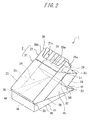
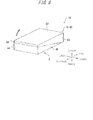
- Fig. 1 and Fig. 2 are perspective views of a hard package (hereinafter, simply referred to as "package") 1 according to Embodiment 1.
- the package 1 is a so-called box-type package with a hinge lid having a substantially rectangular parallelepiped shape.
- the package 1 includes a package body 2 and a lid 3 as a lid member that is pivotably coupled to the package body 2 by means of a hinge.
- Fig. 1 illustrates the state where the package 1 in which the lid 3 is closed is observed obliquely from top right on the front side.
- Fig. 2 illustrates the state where the package 1 in which the lid 3 is opened is observed obliquely from top right on the front side.
- the front side of the package 1 is "front” and that the back side thereof is “rear”.
- the package 1 in the present embodiment is made of, for example, a paper material or a plastic sheet, but the present invention is not limited thereto.
- the package body 2 includes an outer box 21 and an inner frame 22.
- the outer box 21 is a rectangular parallelepiped box body that is obliquely cut out on its upper end side.
- the package body 2 is specifically described.
- the package body 2 includes a front wall 23, a rear wall 24, side walls 25, and a bottom plate 26.
- the front wall 23 and the rear wall 24 each have a rectangular shape.
- the rectangular shape of the rear wall 24 is larger in height than that of the front wall 23, and the rear wall 24 is opposed to the front wall 23.
- the paired side walls 25 respectively couple both the side edges of the front wall 23 to both the side edges of the rear wall 24, and each have a trapezoidal shape with an oblique upper end.
- each side wall 25 is inclined so as to connect the upper end of the front wall 23 to the upper end of the rear wall 24.
- the bottom plate 26 has a rectangular shape, and is coupled to the lower ends of the front wall 23 and the rear wall 24.
- first hinge 51 is formed at the upper end of the rear wall 24 of the outer box 21.
- the first hinge 51 extends between the rear ends of the respective upper end edges 25a of the side walls 25, and pivotably couples the rear wall 24 and the lid 3 to each other.
- the outer box 21 having such a configuration as described above includes an open end 21a at its upper end. Then, the lid 3 is pivotably (turnably) joined (coupled) to the rear opening edge of the open end 21a by means of the first hinge 51.
- the inner frame 22 includes a front frame 28 having a substantially U shape and side frames 29 respectively coupled to both the side edges of the front frame 28.
- the inner frame 22 In the state where part of the inner frame 22 protrudes upward from the open end 21a in an upper part of the outer box 21, the inner frame 22 is bonded to the inner surface of the outer box 21, that is, the inner surfaces of the front wall 23 and the side walls 25.
- the inner frame 22 reinforces the open end 21a of the outer box 21, and also functions to guide opening/closing of the lid 3.
- the front frame 28 includes a cut-out concave portion 28a having a substantially rectangular shape.
- the cut-out concave portion 28a serves to widely open the front of the inner frame 22, and thus enables the tobacco product (housed object) to be easily taken out.
- an ear piece 28b that slightly protrudes laterally is provided in a corner part between the front frame 28 and each side frame 29. When the lid 3 is closed, the ear piece 28b comes into contact with the inner surface of the lid 3, and functions to suppress the lid 3 from being unnecessarily opened.
- the inner frame 22 is not an indispensable member for forming the package 1.
- the inner frame 22 is provided as a member independent of the outer box 21, and is bonded to the inner surface of the outer box 21, but these components may be formed using the same blank material.
- the upper end of the front wall 23 of the outer box 21 may be formed into a shape similar to that of the cut-out concave portion 28a, whereby the inner frame may be omitted.
- the lid 3 includes: a rectangular rear wall 31 coupled to the first hinge 51; a rectangular top plate 32 orthogonally coupled to the rear wall 31; a rectangular front wall 33 orthogonally coupled to the top plate 32; and paired side walls 34.
- the paired side walls 34 each have a trapezoidal shape, and respectively couple the side edges of the rear wall 31, the top plate 32, and the front wall 33.
- the lid 3 is pivotable about the first hinge 51. When the lid 3 is closed, the oblique sides of the side walls 34 thereof, that is, the inclined lower end edges of the side walls 34 thereof respectively fit the upper end edges 25a of the side walls 25 of the outer box 21.
- the package 1 includes a tray member 4 that is provided on the rear wall 24 (back) side of the package body 2 (outer box 21).
- the tray member 4 In the state where the lid 3 is closed (in a lid closing state), the tray member 4 is held in a posture along the rear wall surfaces of the outer box 21 and the lid 3 so as to cover both the rear walls thereof. Meanwhile, upon an opening action of the lid 3 (lid opening action), the tray member 4 fulfills a function of raising the package body 2 up (causing the package body 2 to stand up).
- the tray member 4 includes a first tray portion 41 and a second tray portion 42.
- One end of the first tray portion 41 is joined (bonded) to the bottom plate 26 of the outer box 21, and one end of the second tray portion 42 is joined (bonded) to the top plate 32 of the lid 3.
- another end of the first tray portion 41 and another end of the second tray portion 42 are relatively pivotably joined to each other by means of a second hinge 52.
- the end part of the first tray portion 41 on the side opposite to the second hinge 52 is pivotably joined to the bottom plate 26 of the outer box 21, and the end part of the second tray portion 42 on the side opposite to the second hinge 52 is pivotably joined to the top plate 32 of the lid 3.
- a third hinge 53 is formed along the width direction of the package 1, and the first tray portion 41 is pivotable about the third hinge 53 with respect to the outer box 21.
- a fourth hinge 54 is formed along the width direction of the package 1, and the second tray portion 42 is pivotable about the fourth hinge 54 with respect to the lid 3.
- the first to fourth hinges 51, 52, 53, and 54 are parallel to each other, and are formed along the width direction of the package 1.
- the first tray portion 41 includes: a bottom plate surface covering portion 44 that covers the bottom plate 26 of the package body 2 in the state where the lid 3 is closed, the bottom plate surface covering portion 44 having one end that is pivotably joined to the bottom plate 26 by means of the third hinge 53; and a rear wall surface covering portion 45 having one end that is substantially orthogonally coupled to another end of the bottom plate surface covering portion 44 and having another end at which the second hinge 52 is formed.
- the first tray portion 41 further includes paired side portions 46, 46 that are respectively coupled to the side edges of the bottom plate surface covering portion 44 and the rear wall surface covering portion 45, each have a substantially triangular shape, and are opposed to each other. The side portions 46, 46 are erected perpendicularly to the bottom plate surface covering portion 44 and the rear wall surface covering portion 45.
- the package 1 is formed by interfolding and joining corresponding parts of a first blank B1 for forming the outer box 21 and the lid 3, a second blank B2 for forming the inner frame 22, and a third blank B3 for forming the tray member 4.
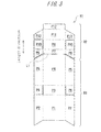
- Fig. 3 is a diagram illustrating the first blank B1.
- Fig. 4 is a diagram illustrating the second blank B2.
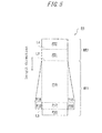
- Fig. 5 is a diagram illustrating the third blank B3.
- Fig. 6 is an exploded perspective view of the package 1 according to the present embodiment.
- a paper material such as cardboard or manila board or a plastic sheet is used for each of the blanks B1, B2, and B3, but the present invention is not limited thereto.
- the first blank B1 includes an outer box region R1 corresponding to the outer box 21 and a lid region R2 corresponding to the lid 3.
- the outer box region R1 includes a front wall panel P1 corresponding to the front wall 23 of the outer box 21, and side wall panels P2, P2 corresponding to the side walls 25 of the outer box 21 are respectively continuous with both the side edges of the front wall panel P1.
- a bottom plate panel P3 corresponding to the bottom plate 26 of the outer box 21 is continuous with the upper edge of the front wall panel P1.
- a rear wall panel P4 corresponding to the rear wall 24 of the outer box 21 is continuous with the bottom plate panel P3, on the side opposite to the front wall panel P1.
- Inner side flaps P5, P5 for the side wall panels P2 are respectively continuous with both the side edges of the rear wall panel P4.
- an inner bottom flap P6 is continuous with the lower end of each inner side flap P5. The inner bottom flaps P6 are put on top of and bonded to the bottom plate panel P3, whereby the bottom plate 26 of the outer box 21 is reinforced.
- the lid region R2 includes a rear wall panel P7 corresponding to the rear wall 31 of the lid 3, and the lower end edge of the rear wall panel P7 is coupled to the rear wall panel P4 of the outer box region 46 across a first hinge line L1 corresponding to the first hinge 51.
- a top plate panel P8 corresponding to the top plate 32 of the lid 3 is continuous with the upper end edge of the rear wall panel P7 of the lid region R2.
- inner side flaps P9 corresponding to parts of the side walls 34 of the lid 3 are respectively continuous with both the side edges of the rear wall panel P4.
- an inner top flap P10 is continuous with the upper end edge of each inner side flap P9.
- the inner top flaps P10 are put on top of and bonded to the top plate panel P8, whereby the top plate 32 is reinforced.
- a front wall panel P11 corresponding to part of the front wall 33 of the lid 3 and an inner front flap P12 corresponding to the other part of the front wall 33 are continuous with the top plate panel P8 in the stated order, on the side opposite to the rear wall panel P7.
- the inner front flap P12 is put on top of and bonded to the front wall panel P11, whereby the front wall 33 is reinforced.
- side wall panels P13 corresponding to the other parts of the side walls 34 of the lid 3 are respectively continuous with both the side edges of the front wall panel P11.
- the inner side flaps P9 are respectively put on top of and bonded to the side wall panels P13, whereby the side walls 34 are reinforced.
- the second blank B2 includes a front panel P14 corresponding to the front frame 28 of the inner frame 22, and side flaps P15 corresponding to the side frames 29 of the inner frame 22 are respectively continuous with both the side edges of the front panel P14.
- a cut is provided in the coupling part of the front panel P14 with each side flap P15. This cut is formed so as to be coincident with an interfold line between the front panel P14 and each side flap P15, which is indicated by a broken line in Fig. 4 , and has a vertically long C shape opened toward the front panel P14.
- this cut slightly protrudes outward from each side frame 29 to become the ear piece 28b.
- the third blank B3 includes a first tray region RT1 corresponding to the first tray portion 41 and a second tray region RT2 corresponding to the second tray portion 42.
- the first tray region RT1 includes a rear wall surface covering panel P16 corresponding to the rear wall surface covering portion 45 of the first tray portion 41.
- the lower end edge of the rear wall surface covering panel P16 is coupled to a bottom plate surface covering panel P17 corresponding to the bottom plate surface covering portion 44.
- side panels P18 corresponding to the side portions 46 are respectively continuous with both the side edges of the rear wall surface covering panel P16.
- an inner bottom flap P19 is continuous with the lower end edge of each side panel P18.
- the inner bottom flaps P19 are put on top of and bonded to the bottom plate surface covering panel P17, whereby the bottom plate surface covering portion 44 is reinforced. Moreover, a bottom plate bonding flap P20 to be bonded to part of the bottom plate panel P3 of the first blank B1, specifically, an area of the bottom plate panel P3 on the rear wall panel P4 side is coupled to the lower end edge of the bottom plate surface covering panel P17.
- a top plate surface covering panel P21 corresponding to the second tray portion 42 is coupled to the upper end edge of the rear wall surface covering panel P16 of the first tray region RT1.
- the top plate surface covering panel P21 and the rear wall surface covering panel P16 are coupled to each other across a second hinge line L2 corresponding to the second hinge 52.
- the bottom plate surface covering panel P17 and the bottom plate bonding flap P20 of the first tray region RT1 are coupled to each other across a third hinge line L3 corresponding to the third hinge 53.
- a top plate bonding flap P22 to be bonded to the top plate panel P8 of the first blank B1 is coupled to the upper end edge of the top plate surface covering panel P21.
- the top plate surface covering panel P21 and the top plate bonding flap P22 are coupled to each other across a fourth hinge line L4 corresponding to the fourth hinge 54.
- the first blank B1 and the second blank B2 are interfolded along the interfold lines indicated by broken lines in Fig. 3 and Fig. 4 , whereby the package body 2 and the lid 3 as illustrated in Fig. 1 , Fig. 2 , and Fig. 6 are formed.
- the reference signs in Fig. 6 respectively correspond to the reference signs of the components described with reference to Figs. 3 to 5 .
- the outer box region R1 of the first blank B1 is interfolded along the interfold lines, the inner bottom flaps P6 are bonded to the bottom plate panel P3, and the inner side flaps P5 are respectively bonded to the side wall panels P2, whereby the outer box 21 of the package body 2 is formed.
- the front panel P14 of the second blank B2 is bonded to the front wall panel P1 of the outer box region R1, whereby the package body 2 in which the outer box 21 and the inner frame 22 are integrated with each other is formed.
- the lid region R2 of the first blank B1 is interfolded along the interfold lines, the inner front flap P12 is bonded to the front wall panel P11, the inner side flaps P9 are respectively bonded to the side wall panels P13, and the inner top flaps P10 are bonded to the top plate panel P8, whereby the lid 3 is formed.
- the third blank B3 is interfolded along the interfold lines indicated by broken lines in Fig. 5 , and the inner bottom flaps P19 are put on top of and bonded to the bottom plate surface covering panel P17, whereby the tray member 4 as illustrated in Fig. 1 , Fig. 2 , and Fig. 6 is formed.
- the bottom plate bonding flap P20 of the third blank B3 is bonded to an area near the rear wall panel P4, of the bottom plate panel P3 of the first blank B1 (an area near the rear wall 24, of the bottom plate 26 of the outer box 21 after its formation) (the bonded areas are hatched in Fig. 6 ).
- the bottom plate bonding flap P20 is bonded to the bottom plate panel P3, to thereby form the bottom plate 26 of the outer box 21 together with the bottom plate panel P3.
- the bottom plate bonding flap P20 bonded to the bottom plate panel P3 and the bottom plate surface covering panel P17 are folded back at the boundary along the third hinge line L3 corresponding to the third hinge 53, and the angle formed by the bottom plate surface covering panel P17 and the bottom plate bonding flap P20 is changeable.
- the outer box 21 of the package body 2 and the first tray portion 41 of the tray member 4 are pivotable relative to each other about the third hinge 53.
- the top plate bonding flap P22 of the third blank B3 is bonded to the top plate panel P8 of the first blank B1 (the bonded areas are hatched in Fig. 6 ), to thereby form the top plate 32 of the lid 3 together with the top plate panel P8.
- the top plate bonding flap P22 bonded to the top plate panel P8 and the top plate surface covering panel P21 are folded back at the boundary along the fourth hinge line L4 corresponding to the fourth hinge 54 after the formation, and the angle formed by the top plate bonding flap P22 and the top plate surface covering panel P21 is changeable.
- the lid 3 and the second tray portion 42 of the tray member 4 are pivotable relative to each other about the fourth hinge 54.
- the direction indicated by an arrow is defined as the length direction of each blank.
- the length of each of the top plate surface covering panel P21 and the top plate bonding flap P22 of the third blank B3 is equal to the length of the top plate panel P8 of the first blank B1 for forming the top plate 32 of the lid 3.
- the length (the length in a direction orthogonal to the second hinge 52) of the second tray portion 42 of the tray member 4 is equal to the depth of the top plate 32 of the lid 3.
- the fourth hinge 54 by means of which the second tray portion 42 is joined to the top plate 32 of the lid 3 is formed in a front end edge part (an edge part on the front wall 33 side) of the top plate 32.
- the length of the second tray portion 42 is equal to a distance in straight line between a rear edge part of the top plate 32 of the lid 3 and the fourth hinge 54.
- the length of the rear wall surface covering panel P16 of the third blank B3 is equal to the sum of the length of the rear wall panel P4 of the outer box region R1 of the first blank B1 and the length of the rear wall panel P7 of the lid region R2 thereof.
- the length (the length in a direction orthogonal to the second hinge 52) of the rear wall surface covering portion 45 of the first tray portion 41 of the tray member 4 is equal to the sum of the height of the rear wall 24 of the outer box 21 of the package body 2 and the height of the rear wall 31 of the lid 3.
- the bottom plate bonding flap P20 of the third blank B3 is bonded to the bottom plate panel P3.
- the length (the length in a direction orthogonal to the second hinge 52) of the bottom plate surface covering portion 44 of the first tray portion 41 is equal to a distance in straight line between a rear edge part of the bottom plate 26 of the package body 2 and the third hinge 53.
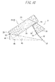
- Fig. 7A to Fig. 7C are diagrams for describing an action of the package 1 according to Embodiment 1.
- Fig. 7A is a diagram illustrating the state where the lid 3 is closed.
- Fig. 7B is a diagram illustrating the state where the lid 3 is opened halfway.
- Fig. 7C is a diagram illustrating the state where the lid 3 is completely opened.
- the connection position between the rear wall surface covering portion 45 and the bottom plate surface covering portion 44 of the first tray portion 41 can be made coincident with the connection position between the rear wall 24 and the bottom plate 26 of the package body 2.
- the length of the second tray portion 42 is equal to the distance in straight line between the rear edge part of the top plate 32 of the lid 3 and the fourth hinge 54.
- the position of the second hinge 52 in the tray member 4 can be made coincident with the position of the rear edge part of the top plate 32 of the lid 3.
- the length of the rear wall surface covering portion 45 of the first tray portion 41 of the tray member 4 is equal to the sum of the height of the rear wall 24 of the outer box 21 and the height of the rear wall 31 of the lid 3.
- the tray member 4 in the tray member 4, the rear wall surface covering portion 45 of the first tray portion 41 can be placed along the rear wall 24 of the outer box 21 and the rear wall 31 of the lid 3, the bottom plate surface covering portion 44 can be placed along the bottom plate 26 of the outer box 21, and the second tray portion 42 can be placed along the top plate 32 of the lid 3.
- the tray member 4 in the state where the lid 3 is closed as illustrated in Fig. 7A , the tray member 4 can be compactly placed along the rear wall of the package body 2 without becoming bulky.
- the package 1 is put on a horizontal surface of a table or the like in the state illustrated in Fig. 7A .
- a user grips both the side portions 46, 46 of the tray member 4 with one hand, and pinches the lid 3 with the other hand, to thereby perform an opening operation of the lid 3.
- the first tray portion 41 is pivotably joined to the package body 2 by means of the third hinge 53
- the second tray portion 42 is pivotably joined to the lid 3 by means of the fourth hinge 54
- the first tray portion 41 and the second tray portion 42 are pivotably coupled to each other by means of the second hinge 52. Accordingly, in conjunction with an opening action of the lid 3, the first tray portion 41 pivots about the third hinge 53, and the second tray portion 42 pivots about the fourth hinge 54.
- the package body 2 can act so as to rise up from the tray member 4.
- the rear wall surface covering portion 45 of the first tray portion 41 and the second tray portion 42 are pivotable relative to each other at the boundary along the second hinge 52, and hence the pivoting action of the first tray portion 41 about the third hinge 53 and the pivoting action of the second tray portion 42 about the fourth hinge 54 are smoothly performed. Accordingly, the above-mentioned rising-up function of the package body 2 is satisfactorily exerted.
- the angle formed by the rear wall surface covering portion 45 of the first tray portion 41 and the second tray portion 42 is a right angle.
- the angle formed by the rear wall surface covering portion 45 and the second tray portion 42 becomes larger from the state illustrated in Fig. 7A to once reach an obtuse angle (see Fig. 7B ).
- this angle gradually becomes smaller in reversal to reach an acute angle from the obtuse angle through the right angle (see Fig. 7C ).
- the angle formed by the top plate 32 of the lid 3 and the second tray portion 42 monotonously becomes larger as the lid 3 is opened wider.
- this angle is about 180°.
- the angle formed by the rear wall surface covering portion 45 of the first tray portion 41 and the rear wall 24 of the package body 2 also monotonously becomes larger as the lid 3 is opened wider. Note that the rear wall surface covering portion 45 and the bottom plate surface covering portion 44 of the first tray portion 41 are orthogonal to each other, and the rear wall 24 and the bottom plate 26 of the package body 2 are orthogonal to each other.
- the angle formed by the bottom plate surface covering portion 44 and the bottom plate 26 that changes along with the pivoting action of the bottom plate surface covering portion 44 about the third hinge 53 is equal to the angle formed by the rear wall surface covering portion 45 and the rear wall 24.
- the angle formed by the rear wall surface covering portion 45 of the first tray portion 41 and the rear wall 24 of the package body 2 becomes larger, the inclination angle at which the package body 2 rises up with respect to the tray member 4 becomes larger.
- the inclination angle of the package body 2 with respect to the tray member 4 becomes largest in the state where the lid 3 is completely opened.
- the lid 3 in its opened state is closed, for example, the lid 3 finally reaches the state illustrated in Fig. 7A from the state illustrated in Fig. 7C through the state illustrated in Fig. 7B . That is, in conjunction with a pivoting action in the direction in which the lid 3 is closed, the rear wall surface covering portion 45 of the first tray portion 41 and the second tray portion 42 pivot relative to each other about the second hinge 52, the first tray portion 41 pivots about the third hinge 53, and the second tray portion 42 pivots about the fourth hinge 54. As a result, the inclination angle of the package body 2 with respect to the tray member 4 becomes smaller. That is, the package body 2 that has risen up with respect to the tray member 4 collapses again toward the tray member 4. Then, in the state where the lid 3 is completely closed, the tray member 4 is placed along the rear wall of the package body 2, and hence the outer shape of the package 1 does not become bulky.
- the package body 2 can automatically stand up from the tray member 4 in conjunction with the opening action of the lid 3 (see Fig. 7B and Fig. 7C ).
- This enables the user of the package 1 to more easily take out the cigarettes housed inside of the package 1.
- a rising-up action of the package body 2 in conjunction with the opening action of the lid 3 is a novel action that does not exist in conventional packages.
- the package 1 having such a novel mode consumers' motivation can be stimulated, and a commercial value of the package 1 or a product including the package 1 and the housed object can be enhanced. Accordingly, the package 1 can contribute to improvement in brand royalty.
- the package 1 according to the present embodiment can be variously modified.
- the first tray portion 41 includes the rear wall surface covering portion 45 and the bottom plate surface covering portion 44, but the bottom plate surface covering portion 44 may be omitted. That is, the first tray portion 41 may simply include the rear wall surface covering portion 45.
- the third hinge 53 may be formed in an end part of the rear wall surface covering portion 45 on the side opposite to the second hinge 52 coupled to the second tray portion 42, and the rear wall surface covering portion 45 may be pivotably joined to the rear wall 24 of the package body 2 by means of the third hinge 53.
- the third hinge 53 may be provided in a lower end edge part (an edge part on the bottom plate 26 side) of the rear wall 24, and may be provided in the middle of the rear wall 24.
- Fig. 8 and Fig. 9 are perspective views of a package 1A according to Embodiment 2.
- Fig. 8 is a diagram corresponding to Fig. 1 in Embodiment 1
- Fig. 9 is a diagram corresponding to Fig. 2 in Embodiment 1.
- the package 1A in the present embodiment is described focusing on difference from the package 1 described in Embodiment 1.
- the package 1A includes the package body 2, the lid 3, and the tray member 4 similar to those of the package 1 in Embodiment 1.
- the package 1A includes a cover member 6 that is pivotably provided to the rear wall 24 of the package body 2 by means of the first hinge 51. When the cover member 6 is opened/closed, the cover member 6 is switchable between the state where the cover member 6 entirely covers the front wall 23 of the package body 2 and the state where the cover member 6 opens the package body 2.
- the cover member 6 has such a shape and dimensions that cover the entire surface of the front wall 23 of the package body 2, and includes a cover body 61 having an inner surface to which the lid 3 is bonded.
- the cover body 61 includes: a front cover portion 62 to which the front wall 33 of the lid 3 is bonded, the front cover portion 62 covering the entire front wall 23 of the package body 2; paired side cover portions 63 to which the side walls 34 of the lid 3 are respectively bonded; and a bottom plate cover portion 64.
- the front cover portion 62 has a rectangular shape, and the width thereof is substantially equal to each of the width of the front wall 23 of the package body 2 and the width of the front wall 33 of the lid 3.
- the length of the front cover portion 62 is substantially equal to the sum of the height of the front wall 33 of the lid 3 and the height of the front wall 23 of the package body 2.
- the side cover portions 63 each have a trapezoidal shape, and the rectangular bottom plate cover portion 64 is provided so as to couple leading end edge parts of the side cover portions 63 and a leading end edge part of the front cover portion 62.
- the cover member 6 is formed by bonding the lid 3 to the inner surface of the cover body 61 having such a configuration as described above.
- the lengths of the side cover portions 63, the bottom plate cover portion 64, the side portions 46, and the bottom plate surface covering portion 44 are determined in the following manner. That is, in the state where the cover member 6 is closed as illustrated in Fig.
- leading end parts of the side cover portions 63 of the cover member 6 respectively confront leading end parts of the side portions 46 of the tray member 4, and a leading end part of the bottom plate cover portion 64 of the cover member 6 confronts a leading end part of the bottom plate surface covering portion 44 of the tray member 4.
- the leading ends of the side cover portions 63 do not interfere with the leading ends of the side portions 46
- the leading end of the bottom plate cover portion 64 does not interfere with the leading end of the bottom plate surface covering portion 44.
- an excessive gap does not occur between the leading ends of the side cover portions 63 and the leading ends of the side portions 46 and between the leading end of the bottom plate cover portion 64 and the leading end of the bottom plate surface covering portion 44.
- Fig. 10A to Fig. 10C are diagrams for describing an action of the package 1A according to Embodiment 2.
- Fig. 10A is a diagram illustrating the state where the cover member 6 is closed.
- Fig. 10B is a diagram illustrating the state where the cover member 6 is opened halfway.
- Fig. 10C is a diagram illustrating the state where the cover member 6 is completely opened.
- Fig. 10A , Fig. 10B , and Fig. 10C respectively correspond to Fig. 7A , Fig. 7B , and Fig. 7C in Embodiment 1.
- the package body 2 and the tray member 4 are the same as those in Embodiment 1.
- the tray member 4 in the state where the cover member 6 is closed, the tray member 4 can be compactly folded and placed on the back side of the package body 2 and the lid 3. That is, in the tray member 4, the rear wall surface covering portion 45 of the first tray portion 41 can be placed along the rear wall 24 of the outer box 21 and the rear wall 31 of the lid 3, the bottom plate surface covering portion 44 can be placed along the bottom plate 26 of the outer box 21, and the second tray portion 42 can be placed along the top plate 32 of the lid 3.
- the tray member 4 in the state where the cover member 6 is closed as illustrated in Fig. 10A , the tray member 4 can be compactly placed along the rear wall of the package body 2 without becoming bulky.
- the leading end of the bottom plate cover portion 64 of the cover member 6 is opposed to the leading end of the bottom plate surface covering portion 44 of the tray member 4, and the leading ends of the side cover portions 63 of the cover member 6 are respectively opposed to the leading ends of the side portions 46 of the tray member 4. This makes the external appearance of the package 1A excellent.
- the cover member 6 When the cover member 6 is opened as described above, in conjunction with the opening action, the first tray portion 41 of the tray member 4 pivots about the third hinge 53, and the second tray portion 42 thereof pivots about the fourth hinge 54. As a result, the second tray portion 42 of the tray member 4 put on the top plate 32 of the lid 3 separates from the top plate 32, and the rear wall surface covering portion 45 of the first tray portion 41 put on the rear wall 24 of the package body 2 separates from the rear wall 24. As a result, as illustrated in Fig. 10B , in conjunction with the opening action of the cover member 6, the package body 2 rises up from the tray member 4.
- the rear wall surface covering portion 45 of the first tray portion 41 and the second tray portion 42 are pivotable relative to each other at the boundary along the second hinge 52, and hence the pivoting action of the first tray portion 41 about the third hinge 53 and the pivoting action of the second tray portion 42 about the fourth hinge 54 are smoothly performed. Accordingly, the above-mentioned rising-up function of the package body 2 is satisfactorily exerted. Then, in the state where the cover member 6 is completely opened as illustrated in Fig. 10C , the inclination angle of the package body 2 with respect to the tray member 4 becomes largest. According to the package 1A, in conjunction with the opening action of the cover member 6, the package body 2 can be raised up from the cover member 6, and hence the user of the package 1A can easily take out the cigarettes housed inside of the package 1A.
- the cover member 6 when the cover member 6 is closed, the entire surface of the front wall 23 of the package body 2 is covered by the cover member 6.
- a warning label about health needs to be presented on the package 1A in a predetermined area or more.
- the inner surface and outer surface of the front cover portion 62 of the cover member 6 can be used as an announcement presenting space, and hence a larger announcement presenting space can be secured compared with conventional hinge-lid-type packages.
- the cover body 61 in the state where the cover member 6 is opened as illustrated in Fig. 9 , the cover body 61 can also function as a saucer for preventing the cigarettes from dropping, thus achieving high convenience.
- the cover member 6 is formed by bonding the lid 3 to the inner surface of the cover body 61, but, not limited thereto, the present embodiment can be variously modified.
- the cover body 61 and the lid 3 may be formed from a common blank instead of being provided as independent members. That is, the entirety or a part of the lid 3 may be formed from a member common to the cover body 61.
- the front wall 33 of the lid 3 and the front cover portion 62 of the cover body 61, the side walls 34 of the lid 3 and the side cover portions 63 of the cover body 61, and the like may be each formed by bonding independent panels, and may be formed from a single panel.
- the cover body 61 in the present embodiment does not cover the top plate 32 of the lid 3, but may include a member that covers the top plate 32 to thereby reinforce the same. As described above, many variations can be adopted for a mode of joining the cover body 61 to the lid 3.
- Fig. 11 is a diagram illustrating a package 1B according to a modified example of Embodiment 2.
- part of the lid is formed from a blank material common to the cover body 61.
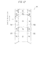
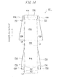
- Fig. 12 and Fig. 13 are diagrams each illustrating a blank for forming the package 1B.
- Fig. 12 is a diagram illustrating a first blank B1'.
- Fig. 13 is a diagram illustrating a second blank B2'.
- Fig. 14 is a diagram illustrating a third blank B3'.
- the second blank B2' is the same as the second blank B2 illustrated in Fig. 4 , and detailed description thereof is omitted.
- FIG. 12 corresponds to the first blank B1 illustrated in Fig. 3
- the third blank B3' illustrated in Fig. 14 corresponds to the third blank B3 illustrated in Fig. 5
- Fig. 12 to Fig. 14 the same components as those illustrated in Fig. 3 to Fig. 5 are denoted by the same reference signs, whereby detailed description thereof is omitted.
- broken lines in each figure represent interfold lines.
- the first blank B1' includes the front wall panel P1, the side wall panels P2, the bottom plate panel P3, the rear wall panel P4, the inner side flaps P5, the inner bottom flaps P6, the rear wall panel P7, the top plate panel P8, the inner side flaps P9, and the inner top flaps P10. These are as described in Embodiment 1.
- the front wall panel P1 and each side wall panel P2 are coupled to each other by means of a front corner panel P31.
- the rear wall panel P4 and each inner side flap P5 are coupled to each other by means of a rear corner panel P32.
- the third blank B3' includes the rear wall surface covering panel P16, the bottom plate surface covering panel P17, the side panels P18, the inner bottom flaps P19, the bottom plate bonding flap P20, and the top plate surface covering panel P21. These are as described in Embodiment 1.
- the third blank B3' further includes rear corner panels P34, a front cover panel P35, paired side cover panels P36, paired front corner panels P37, paired inner top flaps P38, a bottom plate cover panel P39, and an inner bottom flap P40.
- the front cover panel P35 and the side cover panels P36 respectively form the front cover portion 62 and the side cover portions 63 of the package 1B after its assembling.
- the inner bottom flap P40 and the inner top flaps P38 are put on top of and bonded to the bottom plate cover panel P39, whereby the bottom plate cover portion 64 of the package 1B after its assembling is formed (see Fig. 11 ).
- the top plate panel P8, the inner top flaps P10, and the top plate surface covering panel P21 form an upper cover portion 65 of the package 1B after its assembling.
- the upper cover portion 65 forms part of the cover body 61, and is a member corresponding to the top plate 32 of the lid 3 in Embodiment 1.
- Each rear corner panel P34 couples the rear wall surface covering panel P16 to each side panel P18.
- the front cover panel P35 is coupled to an end part of the top plate surface covering panel P21 to which the rear wall surface covering panel P16 is not coupled.
- the front cover panel P35 has substantially the same shape and dimensions as those of the rear wall surface covering panel P16.
- the front corner panel P37 and the side cover panel P36 are coupled to each side edge of the front cover panel P35 in the stated order.
- the inner top flap P38 is coupled to one end of each side cover panel P36.
- the bottom plate cover panel P39 and the inner bottom flap P40 are coupled to an end part of the front cover panel P35 to which the top plate surface covering panel P21 is not coupled, in the stated order.
- the first blank B1', the second blank B2', and the third blank B3' are interfolded along the interfold lines, and corresponding parts thereof are appropriately bonded, whereby the package 1B' illustrated in Fig. 11 is formed.
- the first blank B1' is interfolded along the interfold lines
- the inner bottom flaps P6 are bonded to the bottom plate panel P3
- the inner side flaps P5 are respectively bonded to the side wall panels P2, whereby the outer box 21 of the package body 2 is formed.
- the front panel P14 of the second blank B2' is bonded to the front wall panel P1, whereby the package body 2 in which the outer box 21 and the inner frame 22 are integrated with each other is formed.
- a planar front edge chamfered portion 23A is formed by each front corner panel P31, in a front edge part that defines the boundary between the front wall 23 and each side wall 25 of the package body 2.
- a planar rear edge chamfered portion is formed by each rear corner panel P32, in a rear edge part that defines the boundary between the rear wall 24 and each side wall 25 of the package body 2.
- the third blank B3' is also interfolded along the interfold lines, and the bottom plate bonding flap P20 is bonded to the bottom plate panel P3 of the first blank B1'.
- the inner top flaps P38 and the inner bottom flap P40 are put on top of and bonded to the inner surface of the bottom plate cover panel P39, whereby the bottom plate cover portion 64 of the cover body 61 is formed.
- the side cover panels P36 of the third blank B3' are respectively bonded to the outer surfaces of the inner side flaps P9 of the first blank B1', whereby the two blanks are integrated with each other.
- the front cover panel P35 of the third blank B3' has the same length as that of the rear wall surface covering panel P16.
- the front corner panel P37 is provided between the front cover panel P35 and each side cover panel P36, and hence a planar cover member's chamfered portion 47 is formed in a side edge part that defines the boundary between the front cover portion 62 and each side cover portion 63 of the cover body 61 after the formation of the package 1B.
- the planar cover member's chamfered portion 47 is formed so as to fit the front edge chamfered portion 23A of the package body 2.
- the rear corner panel P34 is provided between the rear wall surface covering panel P16 and each side panel P18, and hence a planar tray member's chamfered portion 48 is formed in a side edge part that defines the boundary between the rear wall surface covering portion 45 and each side portion 46 of the tray member 4 (first tray portion 41) after the formation of the package 1B.
- the tray member's chamfered portion 48 is formed so as to fit the rear edge chamfered portion of the package body 2.
- the cover body 61 and the lid of the package can be formed from the single blank material. Moreover, as described above, each corner portion of the package 1B is chamfered.
- the front edge chamfered portions 23A are respectively provided in the front edge parts of the package body 2, when the cover member 6 is closed, it is possible to suppress the side cover portions 63 of the cover body 61 from interfering with the front edge parts of the package body 2 and thus hindering the closing of the cover member 6. Accordingly, if the front edge chamfered portions 23A formed in the package body 2 are applied in combination of the cover member 6 that covers the entire front wall 23 of the package body 2, the significance of existence thereof is more remarkable.
- edge parts of the package body 2, the cover member 6, and the tray member 4 may be each shaped into an arc-like round corner (edge) instead of the chamfered corner (edge), and effects similar to the chamfered corner can be produced even in this case.
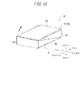
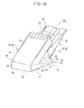
- Fig. 15 and Fig. 16 are perspective views of a package 1B' according to a second modified example.
- the package 1B' is the same as the package 1B in that the package 1B' includes the cover member 6 that covers the entire surface of the front wall 23 of the package body 2, but is different from the package 1B in that the cover member 6 does not include the bottom plate cover portion 64.
- the cover member 6 (lid member) of the package 1B' includes the front cover portion 62 that covers the entire front wall 23 of the package body 2, the paired side cover portions 63, and the upper cover portion 65.
- the front cover portion 62 has a rectangular shape, and the width thereof is substantially equal to the width of the front wall 23 of the package body 2. Moreover, the length of the front cover portion 62 is substantially equal to the height of the package 1B'.
- the side cover portions 63 each have a substantially triangular shape, and the edge parts of the side cover portions 63 are respectively coupled to the leading end edge parts of the front cover portion 62.
- the cover member 6 according to the package 1B' does not include the bottom plate cover portion 64 illustrated in Fig. 9 and Fig. 11 .
- the sizes of the side cover portions 63 and the side portions 46 are determined in the following manner. That is, in the state where the cover member 6 is closed as illustrated in Fig. 15 , the edge parts of the side cover portions 63 of the cover member 6 respectively confront the leading end parts of the side portions 46 of the tray member 4. As a result, the leading ends of the side cover portions 63 and the side portions 46 are suppressed from interfering with each other. Moreover, a large gap does not occur between the leading ends of the side cover portions 63 and the leading ends of the side portions 46.
- a basic structure of the tray member 4 of the package 1B' is substantially equivalent to that of the tray member 4 of each of the packages 1A and 1B. That is, the tray member 4 includes the first tray portion 41 and the second tray portion 42. Moreover, the first tray portion 41 includes: the bottom plate surface covering portion 44 that covers the bottom plate 26 of the package body 2 in the state where the lid 3 is closed; the rear wall surface covering portion 45 that covers the rear wall 24; and the side portions 46 that respectively cover the side walls 25.
- the third hinge 53 by means of which the bottom plate surface covering portion 44 of the first tray portion 41 is coupled to the package body 2 is formed along a front end edge part of the bottom plate 26, that is, an edge part that defines the boundary between the bottom plate 26 and the front wall 23.
- the package body 2 can automatically stand up from the tray member 4 in conjunction with the opening action of the cover member 6 as the lid member. This enables the user of the package 1B' to easily take out the cigarettes housed inside of the package body 2.
- the rising-up action of the package body 2 in conjunction with the opening action of the cover member 6 is a novel action that does not exist in conventional packages, and consumers' motivation can be stimulated as described above.
- the inner surface and outer surface of the front cover portion 62 of the cover member 6 can be effectively used as an announcement presenting space.
- the cover member 6 of the package 1B' includes the front cover portion 62 having such a size that covers substantially the entire surface of the front wall 23 of the package body 2, and hence a larger announcement presenting space can be secured compared with conventional hinge-lid-type packages.
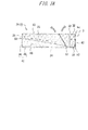
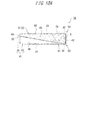
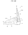
- Fig. 17A and Fig. 17B are cross sectional views each illustrating a configuration of a package 1C according to Embodiment 3.
- the package 1C in the present embodiment is the same as the package 1A in Embodiment 2 except that a flat plate spring member 7 is provided in a cigarette housing space.
- the package 1C is described focusing on the flat plate spring member 7.
- the flat plate spring member 7 is a thin flat plate member, and is made of a paper material in the present embodiment, similarly to the package body 2 and the like.
- the flat plate spring member 7 has a rectangular shape, and includes a first region portion 71 fixed to the package body 2 and a second region portion 72 fixed to the lid 3.
- a body-side attachment portion 73 and a lid-side attachment portion 74 are respectively formed on the outer end sides of the first region portion 71 and the second region portion 72.
- An adhesive is applied to the body-side attachment portion 73 of the first region portion 71, whereby the body-side attachment portion 73 is bonded to the inner surface of the package body 2.
- a fifth hinge 55 is formed at the boundary between the first region portion 71 and the second region portion 72.
- the fifth hinge 55 is formed parallel to the first hinge 51.
- the first region portion 71 is bonded to the inner surface of the rear wall 24 of the package body 2 (outer box 21), by means of the body-side attachment portion 73 formed on the outer end side thereof. Moreover, the second region portion 71 is bonded to the inner surface of the top plate 32 of the lid 3, by means of the lid-side attachment portion 74 formed on the outer end side thereof.
- the fifth hinge 55 is placed at a position higher than the first hinge 51 in the height direction of the package 1C (corresponding to the direction from the bottom plate 26 to the top plate 32 and the direction along the front wall 23 and the rear wall 24). Accordingly, part of the first region portion 71 protrudes from the upper part of the outer box 21 of the package body 2.
- the first region portion 71 of the flat plate spring member 7 is fixed to the inner surface of the package body 2, and the second region portion 72 thereof is fixed to the inner surface of the lid 3, whereby a free pivot of the lid 3 with respect to the package body 2 is restricted.
- the flat plate spring member 7 is maintained in a first tilted state in which the first region portion 71 is placed along the rear wall 24 of the package body 2 while the second region portion 72 is tilted toward the front of the package 1B with respect to the first region portion 71.
- the cover member 6 is opened, in conjunction with the opening action, the first region portion 71 and the second region portion 72 of the flat plate spring member 7 pivot relative to each other about the fifth hinge 55.
- the tilt angle of the second region portion 72 with respect to the first region portion 71 gradually becomes gentler (shallower).
- the flat plate spring member 7 in the first tilted state pivots about the fifth hinge 55 while moderately bending due to its own flexural rigidity.
- the flat plate spring member 7 functions as a plate spring, and pivots while the first region portion 71 and the second region portion 72 are bent, so that the flat plate spring member 7 changes its posture in the direction in which the tilt angle of the second region portion 72 with respect to the first region portion 71 gradually becomes gentler. Then, if the cover member 6 (lid 3) is opened to a given degree of opening or more, the flat plate spring member 7 is reversed at the boundary along the fifth hinge 55, and changes its posture into a second tilted state in which the second region portion 72 is tilted toward the rear of the package 1C with respect to the first region portion 71.
- the user pushes the cover member 6 (lid 3), for example, in the direction in which the cover member 6 (lid 3) is closed, against the urging force that is applied on the inner surface of the lid 3 by the flat plate spring member 7 maintained in the second tilted state. Consequently, the user can switch the flat plate spring member 7 from the second tilted state to the first tilted state, to thereby easily close the cover member 6.
- the package 1C in the present embodiment includes the flat plate spring member 7, and hence the user can hold the cover member 6 (lid 3) in the opened state without gripping the cover member 6 (lid 3). That is, the state where the package body 2 rises up with respect to the tray member 4 can be held as illustrated in Fig. 17B , which enables the user to significantly easily take the cigarettes out of the package 1B. Accordingly, it is possible to provide the package 1C having significantly high usability.
- the posture of the flat plate spring member 7 is switched between the first tilted state and the second tilted state at the time of an opening/closing operation of the cover member 6 (lid 3), and hence such a feeling that the lid 3 is reliably opened/closed can be given to the user.
- an operation feeling, a use feeling, and the like of the package 1C can be improved, and a commercial value of the package 1C can be enhanced.
- the flat plate spring member 7 described in the present embodiment can also be applied to any of the above-mentioned embodiments.
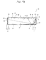
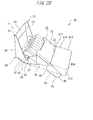
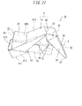
- Figs. 18 to 21 are perspective views of the package 1D.
- Fig. 22 is a side view of the package 1D according to Embodiment 4.
- Fig. 18 and Fig. 19 each illustrate the package 1D in its closed state
- Fig. 20 to Fig. 22 each illustrate the package 1D in its opened state. Note that the top/bottom, front/rear, and left/right directions of the package 1D are as illustrated in Fig. 18 and Fig. 19 .
- the package 1D includes: the outer box 21 (package body 2); the lid 3 as the lid member that is pivotably coupled to the outer box 21 by means of the first hinge 51; and the tray member 4.
- the outer box 21 is a rectangular parallelepiped box body having an open end on its upper end side.
- the outer box 21 includes the front wall 23, the rear wall 24, the paired side walls 25, and the bottom plate 26.
- the front wall 23 and the rear wall 24 are opposed to each other, and the paired side walls 25 couple both the side edges of these walls to each other.
- the bottom plate 26 is coupled to the lower ends of the front wall 23, the rear wall 24, and the side walls 25.
- the outer box 21 having such a configuration as described above has an oblique open end in its upper part.
- edge part formed at the boundary position between the front wall 23 and each side wall 25 of the outer box 21 and the edge part formed at the boundary position between the rear wall 24 and each side wall 25 thereof are chamfered. That is, so-called chamfered edges are respectively formed in these edge parts.
- the first hinge 51 is provided at a rear opening edge of the outer box 21, that is, the upper end of the rear wall 24.
- the first hinge 51 extends along the rear wall 24 of the outer box 21, and pivotably couples the lid 3 to the rear wall 24.
- the lid 3 includes: the rectangular rear wall 31 coupled to the first hinge 51; the rectangular top plate 32 orthogonally coupled to the rear wall 31; the rectangular front wall 33 orthogonally coupled to the top plate 32; and the paired side walls 34.
- the paired side walls 34 respectively couple the side edges of the rear wall 31, the top plate 32, and the front wall 33.
- the lid 3 having such a configuration as described above is pivotable relative to the outer box 21 about the first hinge 51, and can cover the open end of the outer box 21 to open/close the open end thereof.
- the lid 3 includes chamfered front edge parts 36.
- Each front edge part 36 defines a boundary part between the front wall 33 and each side wall 34, and couples the front wall 33 and each side wall 34 to each other.
- the front edge parts 36 are so-called chamfered edges.
- a protruding nail 37 that protrudes downward is formed at the lower end of each front edge part 36.
- the tray member 4 is a cover member provided on the rear wall 24 (back) side of the outer box 21. In the state where the lid 3 is closed, the tray member 4 is held in a posture along the rear wall 24 of the outer box 21 and the rear wall 31 of the lid 3 so as to cover both the surfaces of the rear walls 24 and 31. Meanwhile, upon an opening action of the lid 3, the tray member 4 fulfills a function of raising the outer box 21 up (causing the outer box 21 to stand up).
- the tray member 4 includes the first tray portion 41 and the second tray portion 42.
- the first tray portion 41 is joined (bonded) to the outer box 21, and the second tray portion 42 is joined (bonded) to the lid 3.
- the second hinge 52 is formed at the boundary position between the first tray portion 41 and the second tray portion 42, and the first tray portion 41 and the second tray portion 42 are pivotable relative to each other at the boundary along the second hinge 52.
- the first tray portion 41 of the tray member 4 includes a front wall 411 (front wall surface covering portion), a rear wall 412 (rear wall surface covering portion), paired side walls 413, and a bottom wall 414 (bottom plate surface covering portion).
- the front wall 411 and the rear wall 412 are opposed to each other, and the paired side walls 413 couple both the side edges of these walls to each other.
- the bottom wall 414 is substantially orthogonally coupled to the front wall 411, the rear wall 412, and the side walls 413.
- the bottom wall 414 of the first tray portion 41 has substantially the same shape and size as those of the bottom plate 26 of the outer box 21.
- the bottom plate 26 of the outer box 21 and the bottom wall 414 of the first tray portion 41 are put on top of each other. That is, the bottom wall 414 of the first tray portion 41 is formed so as to cover the bottom plate 26 of the outer box 21 (package body 2) in the state where the lid 3 is closed.
- the rear wall 412 of the first tray portion 41 has a substantially rectangular shape, and the height thereof is substantially equal to the sum of the height of the rear wall 24 of the outer box 21 and the height of the rear wall 31 of the lid 3. Moreover, the width of the rear wall 412 of the first tray portion 41 is slightly larger than the width of the rear wall 24 of the outer box 21. Further, an opening portion 415 is formed in a region of a substantially lower half of the rear wall 412 of the first tray portion 41. The opening portion 415 is formed over the entire width of the rear wall 412. Accordingly, the opening width of the opening portion 415 of the first tray portion 41 is substantially equal to or slightly larger than the width of the rear wall 24 of the outer box 21.
- the edge part formed at the boundary position between the rear wall 412 and each side wall 413 of the first tray portion 41 is chamfered. That is, a so-called chamfered edge is formed in this edge part.
- the rear wall 412 of the first tray portion 41 is formed so as to cover the rear wall 24 of the outer box 21 (package body 2) and the rear wall 31 of the lid 3 in the state where the lid 3 is closed.
- the front wall 411 of the first tray portion 41 has a substantially rectangular shape, and the height thereof is substantially equal to a value obtained by subtracting the height of the front wall 33 of the lid 3 from the height of the package 1D. That is, the sum of the height of the front wall 411 of the first tray portion 41 and the height of the front wall 33 of the lid 3 is substantially equal to the height of the package 1D. Moreover, the width of the front wall 411 of the first tray portion 41 is substantially equal to the width of the front wall 33 of the lid 3, and is slightly larger than the width of the front wall 23 of the outer box 21. Further, the front wall 411 of the first tray portion 41 is relatively pivotably joined to the front wall 23 of the outer box 21 by means of the third hinge 53.
- the third hinge 53 is formed so as to extend along the upper end edge of the front wall 411 of the first tray portion 41.
- the front wall 411 of the first tray portion 41 is formed so as to cover a lower region of the front wall 23 of the outer box 21 (package body 2) in the state where the lid 3 is closed.
- a front edge part 416 is formed at the boundary position between the front wall 411 and each side wall 413 of the first tray portion 41, and is a so-called square edge having a square shape. Further, at the upper end of each front edge part 416 of the first tray portion 41, an oblique engagement edge 417 is formed by obliquely cutting off this upper end part.
- the second tray portion 42 of the tray member 4 has a substantially rectangular shape.
- the second tray portion 42 has substantially the same size as that of the top plate 32 of the lid 3. In the state where the lid 3 is closed, the second tray portion 42 is put on top of the top plate 32 of the lid 3.
- the second tray portion 42 is relatively pivotably joined to the fourth hinge 54 that is formed at the front edge part of the top plate 32 of the lid 3, that is, the edge part that defines the boundary between the top plate 32 and the front wall 33.
- the first to fourth hinges 51, 52, 53, and 54 are parallel to each other, and are formed along the width direction of the package 1D.
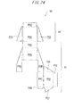
- the package 1D is formed by interfolding and joining corresponding parts of a fourth blank B4 for forming the outer box 21 and part of the lid 3 and a fifth blank B5 for forming the tray member 4 and the other part of the lid 3.
- Fig. 23 illustrates the fourth blank B4
- Fig. 24 illustrates the fifth blank B5. Note that the blanks are described with reference to the top/bottom direction of the figures.
- the fourth blank B4 includes an outer box region R1' corresponding to the outer box 21 and a first lid region R2' corresponding to part of the lid 3.
- the outer box region R1' includes a front wall panel P31 corresponding to the front wall 61 of the outer box 21, and side wall panels P32, P32 corresponding to the side walls 25 of the outer box 21 are respectively continuous with both the side edges of the front wall panel P31.
- a bottom plate panel P33 corresponding to the bottom plate 26 of the outer box 21 is continuous with the upper edge (the upper edge in Fig. 23 ) of the front wall panel P31.
- a rear wall panel P34 corresponding to the rear wall 24 of the outer box 21 is continuous with the bottom plate panel P33, on the side opposite to the front wall panel P31.
- Inner side panels P35, P35 for the side wall panel P32 are respectively continuous with both the side edges of the rear wall panel P34.
- an inner bottom flap P36 is continuous with the lower edge of each inner side panel P35. The inner bottom flaps P36 are put on top of the bottom plate panel P33, whereby the bottom plate 26 of the outer box 21 is reinforced.
- the first lid region R2' includes a rear wall panel P37 corresponding to the rear wall 31 of the lid 3, and the lower edge of the rear wall panel P37 is coupled to the rear wall panel P34 of the outer box region R1' across an interfold line and a slit.
- a top plate panel P38 corresponding to the top plate 32 of the lid 3 is continuous with the upper edge of the rear wall panel P37 of the first lid region R2'.
- inner side flaps P39 corresponding to parts of the side walls 34 of the lid 3 are respectively continuous with both the side edges of the rear wall panel P37.
- an inner top flap P40 is continuous with the upper edge of each inner side flap P39.
- the inner top flaps P40 are put on top of the top plate panel P38, whereby the top plate 32 of the lid 3 is reinforced.
- the fifth blank B5 includes a second lid region R2" corresponding to the other part of the lid 3 and a tray region RT corresponding to the tray member 4.
- the second lid region R2" includes a front wall panel P41 corresponding to the front wall 33 of the lid 3, and an inner front flap P42 for reinforcement of the front wall panel P41 is continuous with the upper edge of the front wall panel P41.
- side wall panels P43 corresponding to the side walls 34 of the lid 3 are respectively continuous with both the side edges of the front wall panel P41.
- a protruding part that protrudes upward is formed in a boundary part between the front wall panel P41 and each side wall panel P43 continuous therewith, and this protruding part forms the protruding nail 37 of the lid 3.
- a top panel P44 corresponding to the second tray portion 42 of the tray member 4 is continuous with the front wall panel P41 of the second lid region R2''.
- a rear wall panel P45 corresponding to the rear wall 412 of the first tray portion 41 is continuous with the lower edge of the top panel P44.
- side wall panels P46 corresponding to the side walls 413 of the first tray portion 41 are respectively continuous with both the side edges of the rear wall panel P45.
- a bottom wall panel P47 corresponding to the bottom wall 414 of the first tray portion 41 is continuous with the lower edge of one of the side wall panels P46.
- a first reinforcing side panel P48 is continuous with the lower edge of the bottom wall panel P47. The first reinforcing side panel P48 is put on top of the other of the side wall panels P46, whereby the side walls 413 of the first tray portion 41 are reinforced.
- a front wall panel P49 corresponding to the front wall 411 of the first tray portion 41 is continuous with the right edge of the bottom wall panel P47.
- a second reinforcing side panel P50 is continuous with the upper edge of the front wall panel P49.
- the second reinforcing side panel P50 is put on top of one of the side wall panels P46, whereby the side walls 413 of the first tray portion 41 are reinforced.
- a third reinforcing side panel P51 is continuous with the lower edge of the front wall panel P49.
- the third reinforcing side panel P51 is put on top of the other of the side wall panels P46, whereby the side walls 413 of the first tray portion 41 are reinforced.
- a joint panel P52 to be bonded to the front wall panel P31 of the outer box region R1' of the fourth blank B4 is continuous with the right edge of the front wall panel P49.
- the fourth blank B4 and the fifth blank B5 are interfolded along the interfold lines indicated by broken lines in Fig. 23 and Fig. 24 .
- the package 1D illustrated in Fig. 18 to Fig. 22 is formed.
- the inner bottom flaps P36 are put on top of the bottom plate panel P33, and the inner side flaps P35 are respectively put on top of and bonded to the side wall panels P32, whereby the outer box 21 is formed.
- the chamfered edge that couples the front wall 23 and each side wall 25 of the outer box 21 is formed by a double interfold line at the boundary position between the front wall panel P31 and each side wall panel P32.
- the chamfered edge that couples the rear wall 24 and each side wall 25 of the outer box 21 is formed by a double interfold line at the boundary position between the rear wall panel P34 and each inner side panel P35.
- the inner top flaps P40 are put on top of the top plate panel P38, and the inner side flaps P39 are respectively put on top of and bonded to the side wall panels P43, whereby the lid 3 is formed.
- the inner front flap P42 may be bonded to the front wall panel P41, and may not be bonded thereto after being folded back with respect to the front wall panel P41.
- the chamfered edge that couples the front wall 33 and each side wall 34 of the lid 3 is formed by a double interfold line at the boundary position between the front wall panel P41 and each side wall panel P43.
- the second reinforcing side panel P50 is bonded to one of the side wall panels P46, and the first reinforcing side panel P48 and the third reinforcing side panel P51 are bonded to the other of the side wall panels P46.
- the joint panel P52 is bonded to the front wall panel P31 of the fourth blank B4, whereby the tray member 4 is formed.
- the chamfered edge that couples the rear wall 412 and each side wall 413 of the first tray portion 41 of the tray member 4 is formed by a double interfold line at the boundary position between the rear wall panel P45 and each side wall panel P46 of the tray region RT.
- first hinge 51 is formed by the interfold line and the slit that define the boundary between the rear wall panel P34 of the outer box region R1' and the rear wall panel P37 of the first lid region R2'.
- second hinge 52 is formed by the interfold line that defines the boundary between the rear wall panel P45 and the top panel P44 of the tray region RT.
- third hinge 53 is formed by the interfold line that defines the boundary between the joint panel P52 and the front wall panel P49 of the tray region RT.
- fourth hinge 54 is formed by the interfold line that defines the boundary between the front wall panel P41 of the second lid region R2" and the top panel P44 of the tray region RT.
- the depth of the bottom wall 414 is equal to the depth of the bottom plate 26 of the outer box 21, and the height of the rear wall 412 is equal to the sum of the height of the rear wall 24 of the outer box 21 and the height of the rear wall 31 of the lid 3.
- the depth of the second tray portion 42 is equal to the depth of the top plate 32 of the lid 3.
- the package 1D is put on a horizontal surface of a table or the like.
- the user grips both the side walls 413 of the first tray portion 41 of the outer tray 21 with one hand, and pinches the lid 3 with the other hand, to thereby open the lid 3. That is, the user pivots the lid 3 about the first hinge 51 with respect to the outer box 21, to thereby open the lid 3.
- the first tray portion 41 of the tray member 4 is pivotably joined to the outer box 21 of the package 1D by means of the third hinge 53.
- the second tray portion 42 of the tray member 4 is pivotably joined to the lid 3 by means of the fourth hinge 54.
- the first tray portion 41 and the second tray portion 42 of the tray member 4 are pivotably coupled to each other by means of the second hinge 52. Accordingly, if an opening action of the lid 3 is performed, in conjunction therewith, the first tray portion 41 and the second tray portion 42 pivot about the second hinge 52, the first tray portion 41 pivots about the third hinge 53 with respect to the outer box 21, and the second tray portion 42 pivots about the fourth hinge 54 with respect to the lid 3.
- the second tray portion 42 put on the top plate 32 of the lid 3 separates from the top plate 32
- the rear wall 412 of the first tray portion 41 put on the rear wall 24 of the outer box 21 separates from the rear wall 24 of the outer box 21.
- the opening portion 415 having the opening width that is substantially equal to or slightly larger than the width of the rear wall 24 of the outer box 21 is formed in the rear wall 412 of the first tray portion 41.
- the first tray portion 41 can be pivoted about the third hinge 53 without interfering with the rear wall 24 of the outer box 21.
- the outer box 21 acts so as to rise up from the tray member 4.
- the first tray portion 41 and the second tray portion 42 pivot about the second hinge 52.
- the first tray portion 41 pivots about the third hinge 53 with respect to the outer box 21, and the second tray portion 42 pivots about the fourth hinge 54 with respect to the lid 3.
- the inclination angle of the outer box 21 with respect to the tray member 4 becomes smaller. That is, the outer box 21 that has risen up with respect to the tray member 4 collapses again into such a posture along the tray member 48, and comes into the state illustrated in Fig. 18 and Fig. 19 .
- the outer box 21 can automatically stand up from the tray member 4 in conjunction with the opening action of the lid 3. This enables the user to easily take out the cigarettes housed inside of the package 1D.
- the package 1C includes a lock mechanism formed of a combination of the protruding nails 37 provided to the lid 3 and the oblique engagement edges 417 provided to the first tray portion 9 of the tray member 4.
- the protruding nails 37 and the oblique engagement edges 417 of the lock mechanism are provided so as to be engaged with each other when the lid 3 is closed.
- the front edge parts 416 of the first tray portion 41 of the tray member 4 are formed as square edges.
- the front edge parts 36 of the lid 3 are formed as chamfered edges. Accordingly, in the state where the lid 3 is closed, the front edge parts 36 of the lid 3 are located on the inner side in a cross-sectional direction of the package 1D than the front edge parts 416 of the first tray portion 41.
- the protruding nails 37 of the lid 3 are respectively engaged with the oblique engagement edges 417 of the tray member 4.
- the lock mechanism that functions as described above, the closed lid 3 can be suppressed from being unnecessarily opened, and the lid closing property of the package 1D can be improved.
- the package 1D includes the lock mechanism formed of the combination of the protruding nails 37 and the oblique engagement edges 417, in order to improve the lid closing property, but this lock mechanism is not an indispensable component, and may be omitted as appropriate.
- the box-type package according to the present invention can be carried out by combining the embodiments as much as possible.
- the tobacco product such as filtered cigarettes and non-filtered cigarettes is taken as a preferred application example of the housed object that is housed in the box-type package, but the present invention is not limited thereto, and articles other than the tobacco product may be housed in the package.
Landscapes
- Engineering & Computer Science (AREA)
- Mechanical Engineering (AREA)
- Cartons (AREA)
- Packaging Of Annular Or Rod-Shaped Articles, Wearing Apparel, Cassettes, Or The Like (AREA)
Abstract
Description
- The present invention relates to a hard package.
- Up to now, a soft-pack-type package, a hard package, and the like are known as a package for housing a housed object such as a tobacco product. A hard package with a hinge lid is known as one mode of the hard package, and this hard package includes an upper lid (hinge lid) that is openably/closably coupled to a package body by means of a hinge. The hard package of this type normally has a box-like outer shape, and the package body that houses a bundle of cigarettes and a lid member for opening/closing an open end formed in an upper part of the package body are pivotably coupled to each other by means of a hinge provided along an edge part of the open end.
- Patent document 1: Japanese Patent No.
4011542 - Patent document 2: Japanese Patent No.
4689928 - Patent document 3: Japanese National Publication of International Patent Application No.
2008-531409 - Patent document 4: European Patent Laid-Open No.
0193365 - Patent document 5: European Patent Laid-Open No.
1260449 - Such a hard package with a hinge lid needs to have a function of enabling a housed object to be easily taken out. The present invention, which has been made in view of the above-mentioned circumstances, has an object to provide a hard package that enables a housed object to be easily taken out.
- The present invention adopts the following solutions in order to achieve the above-mentioned object. A hard package according to the present invention includes: a package body having an open end in an upper part thereof and having a substantially rectangular parallelepiped shape; a lid member that is pivotably coupled to a rear opening edge of the open end by means of a first hinge and opens/closes the open end; and a tray member provided on a rear wall side of the package body, the tray member including a first tray portion joined to the package body and a second tray portion joined to the lid member, the first tray portion and the second tray portion being pivotably joined to each other by means of a second hinge. When the first tray portion and the second tray portion pivot relative to each other about the second hinge in conjunction with an opening action of the lid member, the package body rises up with respect to the tray member. According to the hard package having such a configuration as described above, in the state where the package body rises up with respect to the tray member, a housed object can be taken out, and hence taking out the housed object is facilitated.
- In the hard package, an end part of the first tray portion on a side opposite to the second hinge may be joined to a bottom plate or a rear wall of the package body so as to be pivotable about a third hinge formed along a width direction of the package, an end part of the second tray portion on a side opposite to the second hinge may be joined to a top plate of the lid member so as to be pivotable about a fourth hinge formed along the width direction of the package, and the second hinge may be formed parallel to the third hinge and the fourth hinge. Then, the first tray portion may pivot about the third hinge, and the second tray portion may pivot about the fourth hinge, in conjunction with the opening action of the lid member.
- Here, the third hinge may be formed in the bottom plate of the package body. In this case, the first tray portion may include: a bottom plate surface covering portion that covers the bottom plate of the package body in a state where the lid member is closed, the bottom plate surface covering portion having one end that is pivotably joined to the bottom plate by means of the third hinge; and a rear wall surface covering portion having one end that is substantially orthogonally coupled to another end of the bottom plate surface covering portion and having another end at which the second hinge is formed. Moreover, in the hard package, an end part of the first tray portion on a side opposite to the second hinge may be joined to a front wall of the package body so as to be pivotable about a third hinge formed along a width direction of the package, an end part of the second tray portion on a side opposite to the second hinge may be joined to a top plate of the lid member so as to be pivotable about a fourth hinge formed along the width direction of the package, and the second hinge may be formed parallel to the third hinge and the fourth hinge. The first tray portion may include: a bottom plate surface covering portion that covers a bottom plate of the package body in a state where the lid member is closed; a rear wall surface covering portion that covers a rear wall of the package body, the rear wall surface covering portion having one end coupled to the bottom plate surface covering portion and having another end at which the second hinge is formed; and a front wall surface covering portion that at least covers a lower region of the front wall of the package body, the front wall surface covering portion having one end coupled to the bottom plate surface covering portion and having another end at which the third hinge is formed. The first tray portion may pivot about the third hinge, and the second tray portion may pivot about the fourth hinge, in conjunction with the opening action of the lid member. The rear wall surface covering portion may have an opening portion formed therein for suppressing the first tray portion from interfering with the rear wall of the package body when the first tray portion pivots. Moreover, it is preferable that a length of the bottom plate surface covering portion be equal to a distance in straight line between a rear edge part of the bottom plate of the package body and the third hinge and that a length of the rear wall surface covering portion be equal to a sum of a height of the rear wall of the package body and a height of a rear wall of the lid member. Moreover, it is preferable that a length of the second tray portion be equal to a distance in straight line between a rear edge part of the top plate of the lid member and the fourth hinge. Accordingly, in the state where the lid member is closed, the tray member can be compactly placed on the back side of the package body without becoming bulky.
- Moreover, the hard package may further include a flat plate spring member placed inside of the package, the flat plate spring member having one end fixed to an inner surface of the package body and having another end fixed to an inner surface of the lid member. In this case, the flat plate spring member may include a fifth hinge parallel to the first hinge, a first region portion joined to the package body, and a second region portion joined to the lid member. When the first region portion and the second region portion pivot relative to each other at a boundary along the fifth hinge in conjunction with an opening/closing action of the lid member, a posture of the flat plate spring member may be switchable between: a first tilted state in which the second region portion is tilted frontward with respect to the first region portion; and a second tilted state in which the second region portion is tilted rearward with respect to the first region portion. When the posture of the flat plate spring member that has been switched from the first tilted state to the second tilted state in conjunction with the opening action of the lid member is held in the second tilted state, a state where the package body rises up with respect to the tray member may be maintained.
- Moreover, the lid member may cover a substantially entire surface of a front wall of the package body when the lid member is closed. More preferably, the lid member may cover the bottom plate of the package body. This improves the lid closing property of the lid member. Further, the edges of the package may each have a chamfered or rounded shape.
- The housed object that is housed in the hard package is not particularly limited, but a set of rod-like articles, for example, a tobacco product can be taken as a preferred example of the housed object. That is, the housed object according to the present invention may be the tobacco product. Note that examples of the tobacco product include cigarettes (filtered cigarettes and non-filtered cigarettes (without a filter)), cigars, cigarillos, snus, snuff, chewing tobacco, and electronic cigarettes.
- Note that the solutions provided by the present invention can be adopted in combination as much as possible.
- According to the present invention, it is possible to easily take a housed object out of a hard package.
-
- [
Fig. 1] Fig. 1 is a perspective view of a package according toEmbodiment 1. - [
Fig. 2] Fig. 2 is a perspective view of the package according toEmbodiment 1. - [
Fig. 3] Fig. 3 is a diagram illustrating a first blank of the package according toEmbodiment 1. - [
Fig. 4] Fig. 4 is a diagram illustrating a second blank of the package according toEmbodiment 1. - [
Fig. 5] Fig. 5 is a diagram illustrating a third blank of the package according to Embodiment 1. - [
Fig. 6] Fig. 6 is an exploded perspective view of the package according toEmbodiment 1. - [
Fig. 7A] Fig. 7A is a diagram for describing an action of the package according toEmbodiment 1. - [
Fig. 7B] Fig. 7B is a diagram for describing the action of the package according toEmbodiment 1. - [
Fig. 7C] Fig. 7C is a diagram for describing the action of the package according toEmbodiment 1. - [
Fig. 8] Fig. 8 is a perspective view of a package according toEmbodiment 2. - [
Fig. 9] Fig. 9 is a perspective view of the package according to Embodiment 2. - [
Fig. 10A] Fig. 10A is a diagram for describing an action of the package according toEmbodiment 2. - [
Fig. 10B] Fig. 10B is a diagram for describing the action of the package according toEmbodiment 2. - [
Fig. 10C] Fig. 10C is a diagram for describing the action of the package according toEmbodiment 2. - [
Fig. 11] Fig. 11 is a diagram illustrating a package according to a modified example ofEmbodiment 2. - [
Fig. 12] Fig. 12 is a diagram illustrating a first blank of the package according to the modified example ofEmbodiment 2. - [
Fig. 13] Fig. 13 is a diagram illustrating a second blank of the package according to the modified example ofEmbodiment 2. - [
Fig. 14] Fig. 14 is a diagram illustrating a third blank of the package according to the modified example ofEmbodiment 2. - [
Fig. 15] Fig. 15 is a perspective view of a package according to a second modified example ofEmbodiment 2. - [
Fig. 16] Fig. 16 is a perspective view of the package according to the second modified example ofEmbodiment 2. - [
Fig. 17A] Fig. 17A is a cross sectional view illustrating a configuration of a package according toEmbodiment 3. - [
Fig. 17B] Fig. 17B is a cross sectional view illustrating the configuration of the package according toEmbodiment 3. - [
Fig. 18] Fig. 18 is a perspective view of a package according toEmbodiment 4. - [
Fig. 19] Fig. 19 is a perspective view of the package according toEmbodiment 4. - [
Fig. 20] Fig. 20 is a perspective view of the package according toEmbodiment 4. - [
Fig. 21] Fig. 21 is a perspective view of the package according toEmbodiment 4. - [
Fig. 22] Fig. 22 is a side view of the package according toEmbodiment 4. - [
Fig. 23] Fig. 23 is a diagram illustrating a fourth blank of the package according toEmbodiment 4. - [
Fig. 24] Fig. 24 is a diagram illustrating a fifth blank of the package according toEmbodiment 4. - Now, embodiments of a hard package according to the present invention are described with reference to the drawings. A housed object that is housed in the hard package to which the present invention is applied is not limited to a particular object, but description is given here of an example case where a tobacco product such as filtered cigarettes and non-filtered cigarettes is housed in the package. Moreover, the technical range of the present invention is not simply limited to the dimensions, materials, shapes, relative placements, and the like of components described in the present embodiments, unless specific description is particularly given.
-
Fig. 1 andFig. 2 are perspective views of a hard package (hereinafter, simply referred to as "package") 1 according toEmbodiment 1. Thepackage 1 is a so-called box-type package with a hinge lid having a substantially rectangular parallelepiped shape. Thepackage 1 includes apackage body 2 and alid 3 as a lid member that is pivotably coupled to thepackage body 2 by means of a hinge. -
Fig. 1 illustrates the state where thepackage 1 in which thelid 3 is closed is observed obliquely from top right on the front side.Fig. 2 illustrates the state where thepackage 1 in which thelid 3 is opened is observed obliquely from top right on the front side. Hereinafter, it is defined herein that the front side of thepackage 1 is "front" and that the back side thereof is "rear". Thepackage 1 in the present embodiment is made of, for example, a paper material or a plastic sheet, but the present invention is not limited thereto. - The
package body 2 includes anouter box 21 and aninner frame 22. Theouter box 21 is a rectangular parallelepiped box body that is obliquely cut out on its upper end side. Thepackage body 2 is specifically described. Thepackage body 2 includes afront wall 23, arear wall 24,side walls 25, and abottom plate 26. Thefront wall 23 and therear wall 24 each have a rectangular shape. The rectangular shape of therear wall 24 is larger in height than that of thefront wall 23, and therear wall 24 is opposed to thefront wall 23. The pairedside walls 25 respectively couple both the side edges of thefront wall 23 to both the side edges of therear wall 24, and each have a trapezoidal shape with an oblique upper end. That is, anupper end edge 25a of eachside wall 25 is inclined so as to connect the upper end of thefront wall 23 to the upper end of therear wall 24. Thebottom plate 26 has a rectangular shape, and is coupled to the lower ends of thefront wall 23 and therear wall 24. - Moreover, a hinge (hereinafter, referred to as "first hinge") 51 is formed at the upper end of the
rear wall 24 of theouter box 21. Thefirst hinge 51 extends between the rear ends of the respective upper end edges 25a of theside walls 25, and pivotably couples therear wall 24 and thelid 3 to each other. Theouter box 21 having such a configuration as described above includes anopen end 21a at its upper end. Then, thelid 3 is pivotably (turnably) joined (coupled) to the rear opening edge of theopen end 21a by means of thefirst hinge 51. - The
inner frame 22 includes afront frame 28 having a substantially U shape and side frames 29 respectively coupled to both the side edges of thefront frame 28. In the state where part of theinner frame 22 protrudes upward from theopen end 21a in an upper part of theouter box 21, theinner frame 22 is bonded to the inner surface of theouter box 21, that is, the inner surfaces of thefront wall 23 and theside walls 25. Theinner frame 22 reinforces theopen end 21a of theouter box 21, and also functions to guide opening/closing of thelid 3. - As is apparent from
Fig. 2 , thefront frame 28 includes a cut-outconcave portion 28a having a substantially rectangular shape. The cut-outconcave portion 28a serves to widely open the front of theinner frame 22, and thus enables the tobacco product (housed object) to be easily taken out. Moreover, anear piece 28b that slightly protrudes laterally is provided in a corner part between thefront frame 28 and eachside frame 29. When thelid 3 is closed, theear piece 28b comes into contact with the inner surface of thelid 3, and functions to suppress thelid 3 from being unnecessarily opened. - Note that the
inner frame 22 is not an indispensable member for forming thepackage 1. Moreover, in the present embodiment, theinner frame 22 is provided as a member independent of theouter box 21, and is bonded to the inner surface of theouter box 21, but these components may be formed using the same blank material. Moreover, the upper end of thefront wall 23 of theouter box 21 may be formed into a shape similar to that of the cut-outconcave portion 28a, whereby the inner frame may be omitted. - The
lid 3 includes: a rectangularrear wall 31 coupled to thefirst hinge 51; a rectangulartop plate 32 orthogonally coupled to therear wall 31; a rectangularfront wall 33 orthogonally coupled to thetop plate 32; and pairedside walls 34. The pairedside walls 34 each have a trapezoidal shape, and respectively couple the side edges of therear wall 31, thetop plate 32, and thefront wall 33. As described above, thelid 3 is pivotable about thefirst hinge 51. When thelid 3 is closed, the oblique sides of theside walls 34 thereof, that is, the inclined lower end edges of theside walls 34 thereof respectively fit the upper end edges 25a of theside walls 25 of theouter box 21. - The
package 1 includes atray member 4 that is provided on the rear wall 24 (back) side of the package body 2 (outer box 21). In the state where thelid 3 is closed (in a lid closing state), thetray member 4 is held in a posture along the rear wall surfaces of theouter box 21 and thelid 3 so as to cover both the rear walls thereof. Meanwhile, upon an opening action of the lid 3 (lid opening action), thetray member 4 fulfills a function of raising thepackage body 2 up (causing thepackage body 2 to stand up). - The
tray member 4 includes afirst tray portion 41 and asecond tray portion 42. One end of thefirst tray portion 41 is joined (bonded) to thebottom plate 26 of theouter box 21, and one end of thesecond tray portion 42 is joined (bonded) to thetop plate 32 of thelid 3. Then, another end of thefirst tray portion 41 and another end of thesecond tray portion 42 are relatively pivotably joined to each other by means of asecond hinge 52. In other words, the end part of thefirst tray portion 41 on the side opposite to thesecond hinge 52 is pivotably joined to thebottom plate 26 of theouter box 21, and the end part of thesecond tray portion 42 on the side opposite to thesecond hinge 52 is pivotably joined to thetop plate 32 of thelid 3. - Here, in the joint part between the
first tray portion 41 and thebottom plate 26 of theouter box 21, athird hinge 53 is formed along the width direction of thepackage 1, and thefirst tray portion 41 is pivotable about thethird hinge 53 with respect to theouter box 21. Moreover, in the joint part between thesecond tray portion 42 and thetop plate 32 of thelid 3, afourth hinge 54 is formed along the width direction of thepackage 1, and thesecond tray portion 42 is pivotable about thefourth hinge 54 with respect to thelid 3. In the present embodiment, the first to fourth hinges 51, 52, 53, and 54 are parallel to each other, and are formed along the width direction of thepackage 1. - The
first tray portion 41 includes: a bottom platesurface covering portion 44 that covers thebottom plate 26 of thepackage body 2 in the state where thelid 3 is closed, the bottom platesurface covering portion 44 having one end that is pivotably joined to thebottom plate 26 by means of thethird hinge 53; and a rear wallsurface covering portion 45 having one end that is substantially orthogonally coupled to another end of the bottom platesurface covering portion 44 and having another end at which thesecond hinge 52 is formed. Thefirst tray portion 41 further includes pairedside portions surface covering portion 44 and the rear wallsurface covering portion 45, each have a substantially triangular shape, and are opposed to each other. Theside portions surface covering portion 44 and the rear wallsurface covering portion 45. - In the present embodiment, the
package 1 is formed by interfolding and joining corresponding parts of a first blank B1 for forming theouter box 21 and thelid 3, a second blank B2 for forming theinner frame 22, and a third blank B3 for forming thetray member 4.Fig. 3 is a diagram illustrating the first blank B1.Fig. 4 is a diagram illustrating the second blank B2.Fig. 5 is a diagram illustrating the third blank B3.Fig. 6 is an exploded perspective view of thepackage 1 according to the present embodiment. In the present embodiment, a paper material such as cardboard or manila board or a plastic sheet is used for each of the blanks B1, B2, and B3, but the present invention is not limited thereto. - As illustrated in
Fig. 3 , the first blank B1 includes an outer box region R1 corresponding to theouter box 21 and a lid region R2 corresponding to thelid 3. The outer box region R1 includes a front wall panel P1 corresponding to thefront wall 23 of theouter box 21, and side wall panels P2, P2 corresponding to theside walls 25 of theouter box 21 are respectively continuous with both the side edges of the front wall panel P1. - Moreover, a bottom plate panel P3 corresponding to the
bottom plate 26 of theouter box 21 is continuous with the upper edge of the front wall panel P1. A rear wall panel P4 corresponding to therear wall 24 of theouter box 21 is continuous with the bottom plate panel P3, on the side opposite to the front wall panel P1. Inner side flaps P5, P5 for the side wall panels P2 are respectively continuous with both the side edges of the rear wall panel P4. Further, an inner bottom flap P6 is continuous with the lower end of each inner side flap P5. The inner bottom flaps P6 are put on top of and bonded to the bottom plate panel P3, whereby thebottom plate 26 of theouter box 21 is reinforced. - The lid region R2 includes a rear wall panel P7 corresponding to the
rear wall 31 of thelid 3, and the lower end edge of the rear wall panel P7 is coupled to the rear wall panel P4 of theouter box region 46 across a first hinge line L1 corresponding to thefirst hinge 51. Moreover, a top plate panel P8 corresponding to thetop plate 32 of thelid 3 is continuous with the upper end edge of the rear wall panel P7 of the lid region R2. Moreover, inner side flaps P9 corresponding to parts of theside walls 34 of thelid 3 are respectively continuous with both the side edges of the rear wall panel P4. Then, an inner top flap P10 is continuous with the upper end edge of each inner side flap P9. The inner top flaps P10 are put on top of and bonded to the top plate panel P8, whereby thetop plate 32 is reinforced. - Further, a front wall panel P11 corresponding to part of the
front wall 33 of thelid 3 and an inner front flap P12 corresponding to the other part of thefront wall 33 are continuous with the top plate panel P8 in the stated order, on the side opposite to the rear wall panel P7. The inner front flap P12 is put on top of and bonded to the front wall panel P11, whereby thefront wall 33 is reinforced. Moreover, side wall panels P13 corresponding to the other parts of theside walls 34 of thelid 3 are respectively continuous with both the side edges of the front wall panel P11. The inner side flaps P9 are respectively put on top of and bonded to the side wall panels P13, whereby theside walls 34 are reinforced. - As illustrated in
Fig. 4 , the second blank B2 includes a front panel P14 corresponding to thefront frame 28 of theinner frame 22, and side flaps P15 corresponding to the side frames 29 of theinner frame 22 are respectively continuous with both the side edges of the front panel P14. Moreover, in the second blank B2, a cut is provided in the coupling part of the front panel P14 with each side flap P15. This cut is formed so as to be coincident with an interfold line between the front panel P14 and each side flap P15, which is indicated by a broken line inFig. 4 , and has a vertically long C shape opened toward the front panel P14. When the second blank B2 is interfolded along the interfold line, this cut slightly protrudes outward from eachside frame 29 to become theear piece 28b. - As illustrated in
Fig. 5 , the third blank B3 includes a first tray region RT1 corresponding to thefirst tray portion 41 and a second tray region RT2 corresponding to thesecond tray portion 42. The first tray region RT1 includes a rear wall surface covering panel P16 corresponding to the rear wallsurface covering portion 45 of thefirst tray portion 41. The lower end edge of the rear wall surface covering panel P16 is coupled to a bottom plate surface covering panel P17 corresponding to the bottom platesurface covering portion 44. Moreover, side panels P18 corresponding to theside portions 46 are respectively continuous with both the side edges of the rear wall surface covering panel P16. Then, an inner bottom flap P19 is continuous with the lower end edge of each side panel P18. The inner bottom flaps P19 are put on top of and bonded to the bottom plate surface covering panel P17, whereby the bottom platesurface covering portion 44 is reinforced. Moreover, a bottom plate bonding flap P20 to be bonded to part of the bottom plate panel P3 of the first blank B1, specifically, an area of the bottom plate panel P3 on the rear wall panel P4 side is coupled to the lower end edge of the bottom plate surface covering panel P17. - Next, in the second tray region RT2, a top plate surface covering panel P21 corresponding to the
second tray portion 42 is coupled to the upper end edge of the rear wall surface covering panel P16 of the first tray region RT1. The top plate surface covering panel P21 and the rear wall surface covering panel P16 are coupled to each other across a second hinge line L2 corresponding to thesecond hinge 52. Note that the bottom plate surface covering panel P17 and the bottom plate bonding flap P20 of the first tray region RT1 are coupled to each other across a third hinge line L3 corresponding to thethird hinge 53. In the second tray region RT2, a top plate bonding flap P22 to be bonded to the top plate panel P8 of the first blank B1 is coupled to the upper end edge of the top plate surface covering panel P21. The top plate surface covering panel P21 and the top plate bonding flap P22 are coupled to each other across a fourth hinge line L4 corresponding to thefourth hinge 54. - The first blank B1 and the second blank B2 are interfolded along the interfold lines indicated by broken lines in
Fig. 3 andFig. 4 , whereby thepackage body 2 and thelid 3 as illustrated inFig. 1 ,Fig. 2 , andFig. 6 are formed. Note that the reference signs inFig. 6 respectively correspond to the reference signs of the components described with reference toFigs. 3 to 5 . The outer box region R1 of the first blank B1 is interfolded along the interfold lines, the inner bottom flaps P6 are bonded to the bottom plate panel P3, and the inner side flaps P5 are respectively bonded to the side wall panels P2, whereby theouter box 21 of thepackage body 2 is formed. Then, the front panel P14 of the second blank B2 is bonded to the front wall panel P1 of the outer box region R1, whereby thepackage body 2 in which theouter box 21 and theinner frame 22 are integrated with each other is formed. - Meanwhile, the lid region R2 of the first blank B1 is interfolded along the interfold lines, the inner front flap P12 is bonded to the front wall panel P11, the inner side flaps P9 are respectively bonded to the side wall panels P13, and the inner top flaps P10 are bonded to the top plate panel P8, whereby the
lid 3 is formed. - Similarly, the third blank B3 is interfolded along the interfold lines indicated by broken lines in
Fig. 5 , and the inner bottom flaps P19 are put on top of and bonded to the bottom plate surface covering panel P17, whereby thetray member 4 as illustrated inFig. 1 ,Fig. 2 , andFig. 6 is formed. At the time of assembling of thepackage 1, the bottom plate bonding flap P20 of the third blank B3 is bonded to an area near the rear wall panel P4, of the bottom plate panel P3 of the first blank B1 (an area near therear wall 24, of thebottom plate 26 of theouter box 21 after its formation) (the bonded areas are hatched inFig. 6 ). In this way, the bottom plate bonding flap P20 is bonded to the bottom plate panel P3, to thereby form thebottom plate 26 of theouter box 21 together with the bottom plate panel P3. - The bottom plate bonding flap P20 bonded to the bottom plate panel P3 and the bottom plate surface covering panel P17 are folded back at the boundary along the third hinge line L3 corresponding to the
third hinge 53, and the angle formed by the bottom plate surface covering panel P17 and the bottom plate bonding flap P20 is changeable. As a result, after the formation of thepackage 1, theouter box 21 of thepackage body 2 and thefirst tray portion 41 of thetray member 4 are pivotable relative to each other about thethird hinge 53. - Moreover, at the time of assembling of the
package 1, the top plate bonding flap P22 of the third blank B3 is bonded to the top plate panel P8 of the first blank B1 (the bonded areas are hatched inFig. 6 ), to thereby form thetop plate 32 of thelid 3 together with the top plate panel P8. Moreover, the top plate bonding flap P22 bonded to the top plate panel P8 and the top plate surface covering panel P21 are folded back at the boundary along the fourth hinge line L4 corresponding to thefourth hinge 54 after the formation, and the angle formed by the top plate bonding flap P22 and the top plate surface covering panel P21 is changeable. As a result, after the formation of thepackage 1, thelid 3 and thesecond tray portion 42 of thetray member 4 are pivotable relative to each other about thefourth hinge 54. - In
Fig. 3 andFig. 5 , the direction indicated by an arrow is defined as the length direction of each blank. Here, the length of each of the top plate surface covering panel P21 and the top plate bonding flap P22 of the third blank B3 is equal to the length of the top plate panel P8 of the first blank B1 for forming thetop plate 32 of thelid 3. As a result, in thepackage 1, the length (the length in a direction orthogonal to the second hinge 52) of thesecond tray portion 42 of thetray member 4 is equal to the depth of thetop plate 32 of thelid 3. In the present embodiment, thefourth hinge 54 by means of which thesecond tray portion 42 is joined to thetop plate 32 of thelid 3 is formed in a front end edge part (an edge part on thefront wall 33 side) of thetop plate 32. As a result, the length of thesecond tray portion 42 is equal to a distance in straight line between a rear edge part of thetop plate 32 of thelid 3 and thefourth hinge 54. - Further, the length of the rear wall surface covering panel P16 of the third blank B3 is equal to the sum of the length of the rear wall panel P4 of the outer box region R1 of the first blank B1 and the length of the rear wall panel P7 of the lid region R2 thereof. As a result, the length (the length in a direction orthogonal to the second hinge 52) of the rear wall
surface covering portion 45 of thefirst tray portion 41 of thetray member 4 is equal to the sum of the height of therear wall 24 of theouter box 21 of thepackage body 2 and the height of therear wall 31 of thelid 3. Moreover, at the time of assembling of thepackage 1, in the state where the interfold position between the bottom plate panel P3 and the rear wall panel P4 is coincident with the interfold position between the rear wall surface covering panel P16 and the bottom plate surface covering panel P17, the bottom plate bonding flap P20 of the third blank B3 is bonded to the bottom plate panel P3. As a result, when the assembling of thepackage 1 is completed, the length (the length in a direction orthogonal to the second hinge 52) of the bottom platesurface covering portion 44 of thefirst tray portion 41 is equal to a distance in straight line between a rear edge part of thebottom plate 26 of thepackage body 2 and thethird hinge 53. - Next, an opening/closing action of the
lid 3 of thepackage 1 is described.Fig. 7A to Fig. 7C are diagrams for describing an action of thepackage 1 according toEmbodiment 1.Fig. 7A is a diagram illustrating the state where thelid 3 is closed.Fig. 7B is a diagram illustrating the state where thelid 3 is opened halfway.Fig. 7C is a diagram illustrating the state where thelid 3 is completely opened. - First, the state where the
lid 3 is closed is described with reference toFig. 7A . In thepackage 1, as described above, the length of the bottom platesurface covering portion 44 is equal to the distance in straight line between the rear edge part of thebottom plate 26 of thepackage body 2 and thethird hinge 53. Hence, in the state where thelid 3 is closed, the connection position between the rear wallsurface covering portion 45 and the bottom platesurface covering portion 44 of thefirst tray portion 41 can be made coincident with the connection position between therear wall 24 and thebottom plate 26 of thepackage body 2. - Moreover, the length of the
second tray portion 42 is equal to the distance in straight line between the rear edge part of thetop plate 32 of thelid 3 and thefourth hinge 54. Hence, in the state where thelid 3 is closed, the position of thesecond hinge 52 in thetray member 4 can be made coincident with the position of the rear edge part of thetop plate 32 of thelid 3. In addition to the above-mentioned conditions, the length of the rear wallsurface covering portion 45 of thefirst tray portion 41 of thetray member 4 is equal to the sum of the height of therear wall 24 of theouter box 21 and the height of therear wall 31 of thelid 3. Hence, in the state where thelid 3 is closed, thetray member 4 can be compactly folded and placed on the back side of thepackage body 2 and thelid 3. That is, in thetray member 4, the rear wallsurface covering portion 45 of thefirst tray portion 41 can be placed along therear wall 24 of theouter box 21 and therear wall 31 of thelid 3, the bottom platesurface covering portion 44 can be placed along thebottom plate 26 of theouter box 21, and thesecond tray portion 42 can be placed along thetop plate 32 of thelid 3. As a result, in the state where thelid 3 is closed as illustrated inFig. 7A , thetray member 4 can be compactly placed along the rear wall of thepackage body 2 without becoming bulky. - Here, for convenience sake, for example, it is assumed that the
package 1 is put on a horizontal surface of a table or the like in the state illustrated inFig. 7A . In the case where the cigarettes housed inside of thepackage 1 are taken out, for example, a user grips both theside portions tray member 4 with one hand, and pinches thelid 3 with the other hand, to thereby perform an opening operation of thelid 3. - As described above, the
first tray portion 41 is pivotably joined to thepackage body 2 by means of thethird hinge 53, and thesecond tray portion 42 is pivotably joined to thelid 3 by means of thefourth hinge 54. Further, thefirst tray portion 41 and thesecond tray portion 42 are pivotably coupled to each other by means of thesecond hinge 52. Accordingly, in conjunction with an opening action of thelid 3, thefirst tray portion 41 pivots about thethird hinge 53, and thesecond tray portion 42 pivots about thefourth hinge 54. - As a result, the
second tray portion 42 of thetray member 4 put on thetop plate 32 of thelid 3 separates from thetop plate 32, and the rear wallsurface covering portion 45 of thefirst tray portion 41 put on therear wall 24 of thepackage body 2 separates from therear wall 24. Consequently, as illustrated inFig. 7B , in conjunction with the opening action of thelid 3, thepackage body 2 can act so as to rise up from thetray member 4. On this occasion, in thetray member 4, the rear wallsurface covering portion 45 of thefirst tray portion 41 and thesecond tray portion 42 are pivotable relative to each other at the boundary along thesecond hinge 52, and hence the pivoting action of thefirst tray portion 41 about thethird hinge 53 and the pivoting action of thesecond tray portion 42 about thefourth hinge 54 are smoothly performed. Accordingly, the above-mentioned rising-up function of thepackage body 2 is satisfactorily exerted. - In the state where the
lid 3 is closed as illustrated inFig. 7A , the angle formed by the rear wallsurface covering portion 45 of thefirst tray portion 41 and thesecond tray portion 42 is a right angle. When the rising-up action of thepackage body 2 is started in conjunction with the opening action of thelid 3, the angle formed by the rear wallsurface covering portion 45 and thesecond tray portion 42 becomes larger from the state illustrated inFig. 7A to once reach an obtuse angle (seeFig. 7B ). After that, if thelid 3 continues to be opened wider to some degree, this angle gradually becomes smaller in reversal to reach an acute angle from the obtuse angle through the right angle (seeFig. 7C ). - Meanwhile, the angle formed by the
top plate 32 of thelid 3 and thesecond tray portion 42 monotonously becomes larger as thelid 3 is opened wider. In the example ofFig. 7C , in the state where thelid 3 is completely opened, this angle is about 180°. Moreover, the angle formed by the rear wallsurface covering portion 45 of thefirst tray portion 41 and therear wall 24 of thepackage body 2 also monotonously becomes larger as thelid 3 is opened wider. Note that the rear wallsurface covering portion 45 and the bottom platesurface covering portion 44 of thefirst tray portion 41 are orthogonal to each other, and therear wall 24 and thebottom plate 26 of thepackage body 2 are orthogonal to each other. Accordingly, the angle formed by the bottom platesurface covering portion 44 and thebottom plate 26 that changes along with the pivoting action of the bottom platesurface covering portion 44 about thethird hinge 53 is equal to the angle formed by the rear wallsurface covering portion 45 and therear wall 24. Then, as the angle formed by the rear wallsurface covering portion 45 of thefirst tray portion 41 and therear wall 24 of thepackage body 2 becomes larger, the inclination angle at which thepackage body 2 rises up with respect to thetray member 4 becomes larger. Then, as illustrated inFig. 7C , the inclination angle of thepackage body 2 with respect to thetray member 4 becomes largest in the state where thelid 3 is completely opened. - Meanwhile, in the case where the
lid 3 in its opened state is closed, for example, thelid 3 finally reaches the state illustrated inFig. 7A from the state illustrated inFig. 7C through the state illustrated inFig. 7B . That is, in conjunction with a pivoting action in the direction in which thelid 3 is closed, the rear wallsurface covering portion 45 of thefirst tray portion 41 and thesecond tray portion 42 pivot relative to each other about thesecond hinge 52, thefirst tray portion 41 pivots about thethird hinge 53, and thesecond tray portion 42 pivots about thefourth hinge 54. As a result, the inclination angle of thepackage body 2 with respect to thetray member 4 becomes smaller. That is, thepackage body 2 that has risen up with respect to thetray member 4 collapses again toward thetray member 4. Then, in the state where thelid 3 is completely closed, thetray member 4 is placed along the rear wall of thepackage body 2, and hence the outer shape of thepackage 1 does not become bulky. - According to the
package 1 having such a configuration as described above, because thetray member 4 is provided, thepackage body 2 can automatically stand up from thetray member 4 in conjunction with the opening action of the lid 3 (seeFig. 7B andFig. 7C ). This enables the user of thepackage 1 to more easily take out the cigarettes housed inside of thepackage 1. Moreover, such a rising-up action of thepackage body 2 in conjunction with the opening action of thelid 3 is a novel action that does not exist in conventional packages. According to thepackage 1 having such a novel mode, consumers' motivation can be stimulated, and a commercial value of thepackage 1 or a product including thepackage 1 and the housed object can be enhanced. Accordingly, thepackage 1 can contribute to improvement in brand royalty. - Note that the
package 1 according to the present embodiment can be variously modified. For example, in thetray member 4 described above, thefirst tray portion 41 includes the rear wallsurface covering portion 45 and the bottom platesurface covering portion 44, but the bottom platesurface covering portion 44 may be omitted. That is, thefirst tray portion 41 may simply include the rear wallsurface covering portion 45. - In this case, the
third hinge 53 may be formed in an end part of the rear wallsurface covering portion 45 on the side opposite to thesecond hinge 52 coupled to thesecond tray portion 42, and the rear wallsurface covering portion 45 may be pivotably joined to therear wall 24 of thepackage body 2 by means of thethird hinge 53. On this occasion, thethird hinge 53 may be provided in a lower end edge part (an edge part on thebottom plate 26 side) of therear wall 24, and may be provided in the middle of therear wall 24. In this case, it is preferable to determine that the length (the length in a direction orthogonal to the second hinge 52) of the rear wallsurface covering portion 45 is equal to the height from thethird hinge 53 in thepackage body 2 to an upper end edge part (an edge part on thetop plate 32 side) of thelid 3. As a result, when thelid 3 is closed, the first tray portion 41 (rear wall surface covering portion 45) can be placed along therear wall 24 of thepackage body 2. - Next,
Embodiment 2 is described.Fig. 8 andFig. 9 are perspective views of apackage 1A according toEmbodiment 2.Fig. 8 is a diagram corresponding toFig. 1 inEmbodiment 1, andFig. 9 is a diagram corresponding toFig. 2 inEmbodiment 1. Hereinafter, thepackage 1A in the present embodiment is described focusing on difference from thepackage 1 described inEmbodiment 1. - The
package 1A includes thepackage body 2, thelid 3, and thetray member 4 similar to those of thepackage 1 inEmbodiment 1. Thepackage 1A includes acover member 6 that is pivotably provided to therear wall 24 of thepackage body 2 by means of thefirst hinge 51. When thecover member 6 is opened/closed, thecover member 6 is switchable between the state where thecover member 6 entirely covers thefront wall 23 of thepackage body 2 and the state where thecover member 6 opens thepackage body 2. Thecover member 6 has such a shape and dimensions that cover the entire surface of thefront wall 23 of thepackage body 2, and includes acover body 61 having an inner surface to which thelid 3 is bonded. - The
cover body 61 includes: afront cover portion 62 to which thefront wall 33 of thelid 3 is bonded, thefront cover portion 62 covering the entirefront wall 23 of thepackage body 2; pairedside cover portions 63 to which theside walls 34 of thelid 3 are respectively bonded; and a bottomplate cover portion 64. Thefront cover portion 62 has a rectangular shape, and the width thereof is substantially equal to each of the width of thefront wall 23 of thepackage body 2 and the width of thefront wall 33 of thelid 3. Moreover, the length of thefront cover portion 62 is substantially equal to the sum of the height of thefront wall 33 of thelid 3 and the height of thefront wall 23 of thepackage body 2. - The
side cover portions 63 each have a trapezoidal shape, and the rectangular bottomplate cover portion 64 is provided so as to couple leading end edge parts of theside cover portions 63 and a leading end edge part of thefront cover portion 62. Thecover member 6 is formed by bonding thelid 3 to the inner surface of thecover body 61 having such a configuration as described above. The lengths of theside cover portions 63, the bottomplate cover portion 64, theside portions 46, and the bottom platesurface covering portion 44 are determined in the following manner. That is, in the state where thecover member 6 is closed as illustrated inFig. 8 , leading end parts of theside cover portions 63 of thecover member 6 respectively confront leading end parts of theside portions 46 of thetray member 4, and a leading end part of the bottomplate cover portion 64 of thecover member 6 confronts a leading end part of the bottom platesurface covering portion 44 of thetray member 4. As a result, the leading ends of theside cover portions 63 do not interfere with the leading ends of theside portions 46, and the leading end of the bottomplate cover portion 64 does not interfere with the leading end of the bottom platesurface covering portion 44. Moreover, an excessive gap does not occur between the leading ends of theside cover portions 63 and the leading ends of theside portions 46 and between the leading end of the bottomplate cover portion 64 and the leading end of the bottom platesurface covering portion 44. - Next, an opening/closing action of the
cover member 6 of thepackage 1A is described.Fig. 10A to Fig. 10C are diagrams for describing an action of thepackage 1A according toEmbodiment 2.Fig. 10A is a diagram illustrating the state where thecover member 6 is closed.Fig. 10B is a diagram illustrating the state where thecover member 6 is opened halfway.Fig. 10C is a diagram illustrating the state where thecover member 6 is completely opened.Fig. 10A ,Fig. 10B , andFig. 10C respectively correspond toFig. 7A ,Fig. 7B , andFig. 7C inEmbodiment 1. - In the
package 1A, thepackage body 2 and thetray member 4 are the same as those inEmbodiment 1. Hence, in the state where thecover member 6 is closed, thetray member 4 can be compactly folded and placed on the back side of thepackage body 2 and thelid 3. That is, in thetray member 4, the rear wallsurface covering portion 45 of thefirst tray portion 41 can be placed along therear wall 24 of theouter box 21 and therear wall 31 of thelid 3, the bottom platesurface covering portion 44 can be placed along thebottom plate 26 of theouter box 21, and thesecond tray portion 42 can be placed along thetop plate 32 of thelid 3. As a result, in the state where thecover member 6 is closed as illustrated inFig. 10A , thetray member 4 can be compactly placed along the rear wall of thepackage body 2 without becoming bulky. - Moreover, as described above, in the state where the
cover member 6 is closed, the leading end of the bottomplate cover portion 64 of thecover member 6 is opposed to the leading end of the bottom platesurface covering portion 44 of thetray member 4, and the leading ends of theside cover portions 63 of thecover member 6 are respectively opposed to the leading ends of theside portions 46 of thetray member 4. This makes the external appearance of thepackage 1A excellent. - Next, description is given of an action when the
open end 21a of thepackage body 2 is opened from the state where thefront wall 23 of thepackage body 2 is covered by thecover member 6. In the case where the cigarettes housed inside of thepackage 1 are taken out, for example, the user grips thetray member 4 with one hand, while moving thecover member 6 upward with the other hand. Consequently, thelid 3 and thecover body 61 pivot in an integrated manner about thefirst hinge 51. As a result, thelid 3 is opened integrally with thecover member 6, so that theopen end 21a is opened. In the present embodiment, thecover member 6 corresponds to the lid member. - When the
cover member 6 is opened as described above, in conjunction with the opening action, thefirst tray portion 41 of thetray member 4 pivots about thethird hinge 53, and thesecond tray portion 42 thereof pivots about thefourth hinge 54. As a result, thesecond tray portion 42 of thetray member 4 put on thetop plate 32 of thelid 3 separates from thetop plate 32, and the rear wallsurface covering portion 45 of thefirst tray portion 41 put on therear wall 24 of thepackage body 2 separates from therear wall 24. As a result, as illustrated inFig. 10B , in conjunction with the opening action of thecover member 6, thepackage body 2 rises up from thetray member 4. - On this occasion, in the
tray member 4, the rear wallsurface covering portion 45 of thefirst tray portion 41 and thesecond tray portion 42 are pivotable relative to each other at the boundary along thesecond hinge 52, and hence the pivoting action of thefirst tray portion 41 about thethird hinge 53 and the pivoting action of thesecond tray portion 42 about thefourth hinge 54 are smoothly performed. Accordingly, the above-mentioned rising-up function of thepackage body 2 is satisfactorily exerted. Then, in the state where thecover member 6 is completely opened as illustrated inFig. 10C , the inclination angle of thepackage body 2 with respect to thetray member 4 becomes largest. According to thepackage 1A, in conjunction with the opening action of thecover member 6, thepackage body 2 can be raised up from thecover member 6, and hence the user of thepackage 1A can easily take out the cigarettes housed inside of thepackage 1A. - Further, according to the
package 1A in the present embodiment, when thecover member 6 is closed, the entire surface of thefront wall 23 of thepackage body 2 is covered by thecover member 6. Here, in the case where cigarettes are housed inside of thepackage 1A, a warning label about health needs to be presented on thepackage 1A in a predetermined area or more. In this regard, according to thepackage 1A, the inner surface and outer surface of thefront cover portion 62 of thecover member 6 can be used as an announcement presenting space, and hence a larger announcement presenting space can be secured compared with conventional hinge-lid-type packages. Moreover, according to thepackage 1A in the present embodiment, in the state where thecover member 6 is opened as illustrated inFig. 9 , thecover body 61 can also function as a saucer for preventing the cigarettes from dropping, thus achieving high convenience. - Note that, in the present embodiment, the
cover member 6 is formed by bonding thelid 3 to the inner surface of thecover body 61, but, not limited thereto, the present embodiment can be variously modified. Moreover, thecover body 61 and thelid 3 may be formed from a common blank instead of being provided as independent members. That is, the entirety or a part of thelid 3 may be formed from a member common to thecover body 61. For example, thefront wall 33 of thelid 3 and thefront cover portion 62 of thecover body 61, theside walls 34 of thelid 3 and theside cover portions 63 of thecover body 61, and the like may be each formed by bonding independent panels, and may be formed from a single panel. Moreover, thecover body 61 in the present embodiment does not cover thetop plate 32 of thelid 3, but may include a member that covers thetop plate 32 to thereby reinforce the same. As described above, many variations can be adopted for a mode of joining thecover body 61 to thelid 3. -
Fig. 11 is a diagram illustrating apackage 1B according to a modified example ofEmbodiment 2. In thepackage 1B according to the present modified example, part of the lid is formed from a blank material common to thecover body 61.Fig. 12 andFig. 13 are diagrams each illustrating a blank for forming thepackage 1B.Fig. 12 is a diagram illustrating a first blank B1'.Fig. 13 is a diagram illustrating a second blank B2'.Fig. 14 is a diagram illustrating a third blank B3'. The second blank B2' is the same as the second blank B2 illustrated inFig. 4 , and detailed description thereof is omitted. Moreover, the first blank B1' illustrated inFig. 12 corresponds to the first blank B1 illustrated inFig. 3 , and the third blank B3' illustrated inFig. 14 corresponds to the third blank B3 illustrated inFig. 5 . InFig. 12 to Fig. 14 , the same components as those illustrated inFig. 3 to Fig. 5 are denoted by the same reference signs, whereby detailed description thereof is omitted. Moreover, broken lines in each figure represent interfold lines. - Similarly to the first blank B1 in
Embodiment 1, the first blank B1' includes the front wall panel P1, the side wall panels P2, the bottom plate panel P3, the rear wall panel P4, the inner side flaps P5, the inner bottom flaps P6, the rear wall panel P7, the top plate panel P8, the inner side flaps P9, and the inner top flaps P10. These are as described inEmbodiment 1. In thepackage 1B, the front wall panel P1 and each side wall panel P2 are coupled to each other by means of a front corner panel P31. Moreover, the rear wall panel P4 and each inner side flap P5 are coupled to each other by means of a rear corner panel P32. - Moreover, similarly to the third blank B3 in
Embodiment 1, the third blank B3' includes the rear wall surface covering panel P16, the bottom plate surface covering panel P17, the side panels P18, the inner bottom flaps P19, the bottom plate bonding flap P20, and the top plate surface covering panel P21. These are as described inEmbodiment 1. The third blank B3' further includes rear corner panels P34, a front cover panel P35, paired side cover panels P36, paired front corner panels P37, paired inner top flaps P38, a bottom plate cover panel P39, and an inner bottom flap P40. - Here, the front cover panel P35 and the side cover panels P36 respectively form the
front cover portion 62 and theside cover portions 63 of thepackage 1B after its assembling. Moreover, the inner bottom flap P40 and the inner top flaps P38 are put on top of and bonded to the bottom plate cover panel P39, whereby the bottomplate cover portion 64 of thepackage 1B after its assembling is formed (seeFig. 11 ). Moreover, the top plate panel P8, the inner top flaps P10, and the top plate surface covering panel P21 form anupper cover portion 65 of thepackage 1B after its assembling. Theupper cover portion 65 forms part of thecover body 61, and is a member corresponding to thetop plate 32 of thelid 3 inEmbodiment 1. - Each rear corner panel P34 couples the rear wall surface covering panel P16 to each side panel P18. Moreover, the front cover panel P35 is coupled to an end part of the top plate surface covering panel P21 to which the rear wall surface covering panel P16 is not coupled. The front cover panel P35 has substantially the same shape and dimensions as those of the rear wall surface covering panel P16. The front corner panel P37 and the side cover panel P36 are coupled to each side edge of the front cover panel P35 in the stated order. Moreover, the inner top flap P38 is coupled to one end of each side cover panel P36. Further, the bottom plate cover panel P39 and the inner bottom flap P40 are coupled to an end part of the front cover panel P35 to which the top plate surface covering panel P21 is not coupled, in the stated order.
- The first blank B1', the second blank B2', and the third blank B3' are interfolded along the interfold lines, and corresponding parts thereof are appropriately bonded, whereby the
package 1B' illustrated inFig. 11 is formed. For example, the first blank B1' is interfolded along the interfold lines, the inner bottom flaps P6 are bonded to the bottom plate panel P3, and the inner side flaps P5 are respectively bonded to the side wall panels P2, whereby theouter box 21 of thepackage body 2 is formed. Then, the front panel P14 of the second blank B2' is bonded to the front wall panel P1, whereby thepackage body 2 in which theouter box 21 and theinner frame 22 are integrated with each other is formed. - Moreover, the inner top flaps P10 of the first blank B1' are put on top of and bonded to the top plate panel P8. Moreover, in the present modified example, a planar front edge chamfered
portion 23A is formed by each front corner panel P31, in a front edge part that defines the boundary between thefront wall 23 and eachside wall 25 of thepackage body 2. Similarly, a planar rear edge chamfered portion (not illustrated) is formed by each rear corner panel P32, in a rear edge part that defines the boundary between therear wall 24 and eachside wall 25 of thepackage body 2. - Meanwhile, the third blank B3' is also interfolded along the interfold lines, and the bottom plate bonding flap P20 is bonded to the bottom plate panel P3 of the first blank B1'. Moreover, the inner top flaps P38 and the inner bottom flap P40 are put on top of and bonded to the inner surface of the bottom plate cover panel P39, whereby the bottom
plate cover portion 64 of thecover body 61 is formed. Further, the side cover panels P36 of the third blank B3' are respectively bonded to the outer surfaces of the inner side flaps P9 of the first blank B1', whereby the two blanks are integrated with each other. Note that the front cover panel P35 of the third blank B3' has the same length as that of the rear wall surface covering panel P16. - In the third blank B3' according to the present modified example, the front corner panel P37 is provided between the front cover panel P35 and each side cover panel P36, and hence a planar cover member's chamfered
portion 47 is formed in a side edge part that defines the boundary between thefront cover portion 62 and eachside cover portion 63 of thecover body 61 after the formation of thepackage 1B. The planar cover member's chamferedportion 47 is formed so as to fit the front edge chamferedportion 23A of thepackage body 2. Further, in the third blank B3', the rear corner panel P34 is provided between the rear wall surface covering panel P16 and each side panel P18, and hence a planar tray member's chamferedportion 48 is formed in a side edge part that defines the boundary between the rear wallsurface covering portion 45 and eachside portion 46 of the tray member 4 (first tray portion 41) after the formation of thepackage 1B. The tray member's chamferedportion 48 is formed so as to fit the rear edge chamfered portion of thepackage body 2. - As the
package 1B illustrated inFig. 11 to Fig. 14 , thecover body 61 and the lid of the package can be formed from the single blank material. Moreover, as described above, each corner portion of thepackage 1B is chamfered. In particular, because the front edge chamferedportions 23A are respectively provided in the front edge parts of thepackage body 2, when thecover member 6 is closed, it is possible to suppress theside cover portions 63 of thecover body 61 from interfering with the front edge parts of thepackage body 2 and thus hindering the closing of thecover member 6. Accordingly, if the front edge chamferedportions 23A formed in thepackage body 2 are applied in combination of thecover member 6 that covers the entirefront wall 23 of thepackage body 2, the significance of existence thereof is more remarkable. Note that the edge parts of thepackage body 2, thecover member 6, and thetray member 4 may be each shaped into an arc-like round corner (edge) instead of the chamfered corner (edge), and effects similar to the chamfered corner can be produced even in this case. -
Fig. 15 andFig. 16 are perspective views of apackage 1B' according to a second modified example. Thepackage 1B' is the same as thepackage 1B in that thepackage 1B' includes thecover member 6 that covers the entire surface of thefront wall 23 of thepackage body 2, but is different from thepackage 1B in that thecover member 6 does not include the bottomplate cover portion 64. Note that, inFig. 15 andFig. 16 , components common to those of the above-mentioned packages are denoted by the same reference signs, whereby detailed description thereof is omitted. - The cover member 6 (lid member) of the
package 1B' includes thefront cover portion 62 that covers the entirefront wall 23 of thepackage body 2, the pairedside cover portions 63, and theupper cover portion 65. Thefront cover portion 62 has a rectangular shape, and the width thereof is substantially equal to the width of thefront wall 23 of thepackage body 2. Moreover, the length of thefront cover portion 62 is substantially equal to the height of thepackage 1B'. - The
side cover portions 63 each have a substantially triangular shape, and the edge parts of theside cover portions 63 are respectively coupled to the leading end edge parts of thefront cover portion 62. Note that thecover member 6 according to thepackage 1B' does not include the bottomplate cover portion 64 illustrated inFig. 9 andFig. 11 . The sizes of theside cover portions 63 and theside portions 46 are determined in the following manner. That is, in the state where thecover member 6 is closed as illustrated inFig. 15 , the edge parts of theside cover portions 63 of thecover member 6 respectively confront the leading end parts of theside portions 46 of thetray member 4. As a result, the leading ends of theside cover portions 63 and theside portions 46 are suppressed from interfering with each other. Moreover, a large gap does not occur between the leading ends of theside cover portions 63 and the leading ends of theside portions 46. - A basic structure of the
tray member 4 of thepackage 1B' is substantially equivalent to that of thetray member 4 of each of thepackages tray member 4 includes thefirst tray portion 41 and thesecond tray portion 42. Moreover, thefirst tray portion 41 includes: the bottom platesurface covering portion 44 that covers thebottom plate 26 of thepackage body 2 in the state where thelid 3 is closed; the rear wallsurface covering portion 45 that covers therear wall 24; and theside portions 46 that respectively cover theside walls 25. In thepackage 1B' according to the present modified example, thethird hinge 53 by means of which the bottom platesurface covering portion 44 of thefirst tray portion 41 is coupled to thepackage body 2 is formed along a front end edge part of thebottom plate 26, that is, an edge part that defines the boundary between thebottom plate 26 and thefront wall 23. According to thepackage 1B' having such a configuration as described above, because thetray member 4 is provided similarly to thepackages package body 2 can automatically stand up from thetray member 4 in conjunction with the opening action of thecover member 6 as the lid member. This enables the user of thepackage 1B' to easily take out the cigarettes housed inside of thepackage body 2. Moreover, such a rising-up action of thepackage body 2 in conjunction with the opening action of thecover member 6 is a novel action that does not exist in conventional packages, and consumers' motivation can be stimulated as described above. Moreover, the inner surface and outer surface of thefront cover portion 62 of thecover member 6 can be effectively used as an announcement presenting space. Thecover member 6 of thepackage 1B' includes thefront cover portion 62 having such a size that covers substantially the entire surface of thefront wall 23 of thepackage body 2, and hence a larger announcement presenting space can be secured compared with conventional hinge-lid-type packages. - Next,
Embodiment 3 is described.Fig. 17A andFig. 17B are cross sectional views each illustrating a configuration of apackage 1C according toEmbodiment 3. Thepackage 1C in the present embodiment is the same as thepackage 1A inEmbodiment 2 except that a flatplate spring member 7 is provided in a cigarette housing space. Here, thepackage 1C is described focusing on the flatplate spring member 7. - The flat
plate spring member 7 is a thin flat plate member, and is made of a paper material in the present embodiment, similarly to thepackage body 2 and the like. The flatplate spring member 7 has a rectangular shape, and includes afirst region portion 71 fixed to thepackage body 2 and asecond region portion 72 fixed to thelid 3. A body-side attachment portion 73 and a lid-side attachment portion 74 are respectively formed on the outer end sides of thefirst region portion 71 and thesecond region portion 72. An adhesive is applied to the body-side attachment portion 73 of thefirst region portion 71, whereby the body-side attachment portion 73
is bonded to the inner surface of thepackage body 2. Similarly, an adhesive is applied to the lid-side attachment portion 74 of thesecond region portion 72, whereby the lid-side attachment portion 74 is fixed (attached) to the inner surface of thelid 3. Moreover, afifth hinge 55 is formed at the boundary between thefirst region portion 71 and thesecond region portion 72. Thefifth hinge 55 is formed parallel to thefirst hinge 51. - The
first region portion 71 is bonded to the inner surface of therear wall 24 of the package body 2 (outer box 21), by means of the body-side attachment portion 73 formed on the outer end side thereof. Moreover, thesecond region portion 71 is bonded to the inner surface of thetop plate 32 of thelid 3, by means of the lid-side attachment portion 74 formed on the outer end side thereof. In the flatplate spring member 7, thefifth hinge 55 is placed at a position higher than thefirst hinge 51 in the height direction of thepackage 1C (corresponding to the direction from thebottom plate 26 to thetop plate 32 and the direction along thefront wall 23 and the rear wall 24). Accordingly, part of thefirst region portion 71 protrudes from the upper part of theouter box 21 of thepackage body 2. - An action of the flat
plate spring member 7 in thepackage 1C having such a configuration as described above is described. Thefirst region portion 71 of the flatplate spring member 7 is fixed to the inner surface of thepackage body 2, and thesecond region portion 72 thereof is fixed to the inner surface of thelid 3, whereby a free pivot of thelid 3 with respect to thepackage body 2 is restricted. - In the state where the cover member 6 (lid 3) is at its closed position as illustrated in
Fig. 17A , the flatplate spring member 7 is maintained in a first tilted state in which thefirst region portion 71 is placed along therear wall 24 of thepackage body 2 while thesecond region portion 72 is tilted toward the front of thepackage 1B with respect to thefirst region portion 71. - Meanwhile, if the
cover member 6 is opened, in conjunction with the opening action, thefirst region portion 71 and thesecond region portion 72 of the flatplate spring member 7 pivot relative to each other about thefifth hinge 55. As a result, the tilt angle of thesecond region portion 72 with respect to thefirst region portion 71 gradually becomes gentler (shallower). In the course in which thecover member 6 pivots from its closed position to its opened position, the flatplate spring member 7 in the first tilted state pivots about thefifth hinge 55 while moderately bending due to its own flexural rigidity. That is, the flatplate spring member 7 functions as a plate spring, and pivots while thefirst region portion 71 and thesecond region portion 72 are bent, so that the flatplate spring member 7 changes its posture in the direction in which the tilt angle of thesecond region portion 72 with respect to thefirst region portion 71 gradually becomes gentler. Then, if the cover member 6 (lid 3) is opened to a given degree of opening or more, the flatplate spring member 7 is reversed at the boundary along thefifth hinge 55, and changes its posture into a second tilted state in which thesecond region portion 72 is tilted toward the rear of thepackage 1C with respect to thefirst region portion 71. - If the flat
plate spring member 7 is switched from the first tilted state to the second tilted state as described above, the inner surface of thetop plate 32 of thelid 3 is held by thesecond region portion 72, whereby a free pivot of the cover member 6 (lid 3) is restricted. As a result, the cover member 6 (lid 3) does not become unstable due to its own weight or paper repulsive force, and the user can maintain thepackage 1C in the opened state illustrated inFig. 17B even without gripping the cover member 6 (lid 3). - In the case where the cover member 6 (lid 3) in the opened state is closed, the user pushes the cover member 6 (lid 3), for example, in the direction in which the cover member 6 (lid 3) is closed, against the urging force that is applied on the inner surface of the
lid 3 by the flatplate spring member 7 maintained in the second tilted state. Consequently, the user can switch the flatplate spring member 7 from the second tilted state to the first tilted state, to thereby easily close thecover member 6. - As described above, the
package 1C in the present embodiment includes the flatplate spring member 7, and hence the user can hold the cover member 6 (lid 3) in the opened state without gripping the cover member 6 (lid 3). That is, the state where thepackage body 2 rises up with respect to thetray member 4 can be held as illustrated inFig. 17B , which enables the user to significantly easily take the cigarettes out of thepackage 1B. Accordingly, it is possible to provide thepackage 1C having significantly high usability. - Then, in the adopted structure, the posture of the flat
plate spring member 7 is switched between the first tilted state and the second tilted state at the time of an opening/closing operation of the cover member 6 (lid 3), and hence such a feeling that thelid 3 is reliably opened/closed can be given to the user. As a result, an operation feeling, a use feeling, and the like of thepackage 1C can be improved, and a commercial value of thepackage 1C can be enhanced. Note that the flatplate spring member 7 described in the present embodiment can also be applied to any of the above-mentioned embodiments. - Next, a
package 1D according toEmbodiment 4 is described. -
Figs. 18 to 21 are perspective views of thepackage 1D.Fig. 22 is a side view of thepackage 1D according toEmbodiment 4.Fig. 18 andFig. 19 each illustrate thepackage 1D in its closed state, andFig. 20 to Fig. 22 each illustrate thepackage 1D in its opened state. Note that the top/bottom, front/rear, and left/right directions of thepackage 1D are as illustrated inFig. 18 andFig. 19 . - The
package 1D includes: the outer box 21 (package body 2); thelid 3 as the lid member that is pivotably coupled to theouter box 21 by means of thefirst hinge 51; and thetray member 4. Theouter box 21 is a rectangular parallelepiped box body having an open end on its upper end side. Theouter box 21 includes thefront wall 23, therear wall 24, the pairedside walls 25, and thebottom plate 26. Thefront wall 23 and therear wall 24 are opposed to each other, and the pairedside walls 25 couple both the side edges of these walls to each other. Thebottom plate 26 is coupled to the lower ends of thefront wall 23, therear wall 24, and theside walls 25. Theouter box 21 having such a configuration as described above has an oblique open end in its upper part. The edge part formed at the boundary position between thefront wall 23 and eachside wall 25 of theouter box 21 and the edge part formed at the boundary position between therear wall 24 and eachside wall 25 thereof are chamfered. That is, so-called chamfered edges are respectively formed in these edge parts. - Moreover, the
first hinge 51 is provided at a rear opening edge of theouter box 21, that is, the upper end of therear wall 24. Thefirst hinge 51 extends along therear wall 24 of theouter box 21, and pivotably couples thelid 3 to therear wall 24. Thelid 3 includes: the rectangularrear wall 31 coupled to thefirst hinge 51; the rectangulartop plate 32 orthogonally coupled to therear wall 31; the rectangularfront wall 33 orthogonally coupled to thetop plate 32; and the pairedside walls 34. The pairedside walls 34 respectively couple the side edges of therear wall 31, thetop plate 32, and thefront wall 33. Thelid 3 having such a configuration as described above is pivotable relative to theouter box 21 about thefirst hinge 51, and can cover the open end of theouter box 21 to open/close the open end thereof. - The
lid 3 includes chamferedfront edge parts 36. Eachfront edge part 36 defines a boundary part between thefront wall 33 and eachside wall 34, and couples thefront wall 33 and eachside wall 34 to each other. Thefront edge parts 36 are so-called chamfered edges. Moreover, a protrudingnail 37 that protrudes downward is formed at the lower end of eachfront edge part 36. - The
tray member 4 is a cover member provided on the rear wall 24 (back) side of theouter box 21. In the state where thelid 3 is closed, thetray member 4 is held in a posture along therear wall 24 of theouter box 21 and therear wall 31 of thelid 3 so as to cover both the surfaces of therear walls lid 3, thetray member 4 fulfills a function of raising theouter box 21 up (causing theouter box 21 to stand up). - The
tray member 4 includes thefirst tray portion 41 and thesecond tray portion 42. Thefirst tray portion 41 is joined (bonded) to theouter box 21, and thesecond tray portion 42 is joined (bonded) to thelid 3. Moreover, thesecond hinge 52 is formed at the boundary position between thefirst tray portion 41 and thesecond tray portion 42, and thefirst tray portion 41 and thesecond tray portion 42 are pivotable relative to each other at the boundary along thesecond hinge 52. - The
first tray portion 41 of thetray member 4 includes a front wall 411 (front wall surface covering portion), a rear wall 412 (rear wall surface covering portion), pairedside walls 413, and a bottom wall 414 (bottom plate surface covering portion). Thefront wall 411 and therear wall 412 are opposed to each other, and the pairedside walls 413 couple both the side edges of these walls to each other. Thebottom wall 414 is substantially orthogonally coupled to thefront wall 411, therear wall 412, and theside walls 413. Thebottom wall 414 of thefirst tray portion 41 has substantially the same shape and size as those of thebottom plate 26 of theouter box 21. In the state where thelid 3 is closed, thebottom plate 26 of theouter box 21 and thebottom wall 414 of thefirst tray portion 41 are put on top of each other. That is, thebottom wall 414 of thefirst tray portion 41 is formed so as to cover thebottom plate 26 of the outer box 21 (package body 2) in the state where thelid 3 is closed. - The
rear wall 412 of thefirst tray portion 41 has a substantially rectangular shape, and the height thereof is substantially equal to the sum of the height of therear wall 24 of theouter box 21 and the height of therear wall 31 of thelid 3. Moreover, the width of therear wall 412 of thefirst tray portion 41 is slightly larger than the width of therear wall 24 of theouter box 21. Further, anopening portion 415 is formed in a region of a substantially lower half of therear wall 412 of thefirst tray portion 41. Theopening portion 415 is formed over the entire width of therear wall 412. Accordingly, the opening width of theopening portion 415 of thefirst tray portion 41 is substantially equal to or slightly larger than the width of therear wall 24 of theouter box 21. Note that the edge part formed at the boundary position between therear wall 412 and eachside wall 413 of thefirst tray portion 41 is chamfered. That is, a so-called chamfered edge is formed in this edge part. Therear wall 412 of thefirst tray portion 41 is formed so as to cover therear wall 24 of the outer box 21 (package body 2) and therear wall 31 of thelid 3 in the state where thelid 3 is closed. - The
front wall 411 of thefirst tray portion 41 has a substantially rectangular shape, and the height thereof is substantially equal to a value obtained by subtracting the height of thefront wall 33 of thelid 3 from the height of thepackage 1D. That is, the sum of the height of thefront wall 411 of thefirst tray portion 41 and the height of thefront wall 33 of thelid 3 is substantially equal to the height of thepackage 1D. Moreover, the width of thefront wall 411 of thefirst tray portion 41 is substantially equal to the width of thefront wall 33 of thelid 3, and is slightly larger than the width of thefront wall 23 of theouter box 21. Further, thefront wall 411 of thefirst tray portion 41 is relatively pivotably joined to thefront wall 23 of theouter box 21 by means of thethird hinge 53. Thethird hinge 53 is formed so as to extend along the upper end edge of thefront wall 411 of thefirst tray portion 41. Thefront wall 411 of thefirst tray portion 41 is formed so as to cover a lower region of thefront wall 23 of the outer box 21 (package body 2) in the state where thelid 3 is closed. - A
front edge part 416 is formed at the boundary position between thefront wall 411 and eachside wall 413 of thefirst tray portion 41, and is a so-called square edge having a square shape. Further, at the upper end of eachfront edge part 416 of thefirst tray portion 41, anoblique engagement edge 417 is formed by obliquely cutting off this upper end part. - Moreover, the
second tray portion 42 of thetray member 4 has a substantially rectangular shape. Thesecond tray portion 42 has substantially the same size as that of thetop plate 32 of thelid 3. In the state where thelid 3 is closed, thesecond tray portion 42 is put on top of thetop plate 32 of thelid 3. Moreover, thesecond tray portion 42 is relatively pivotably joined to thefourth hinge 54 that is formed at the front edge part of thetop plate 32 of thelid 3, that is, the edge part that defines the boundary between thetop plate 32 and thefront wall 33. Note that the first to fourth hinges 51, 52, 53, and 54 are parallel to each other, and are formed along the width direction of thepackage 1D. - The
package 1D is formed by interfolding and joining corresponding parts of a fourth blank B4 for forming theouter box 21 and part of thelid 3 and a fifth blank B5 for forming thetray member 4 and the other part of thelid 3.Fig. 23 illustrates the fourth blank B4, andFig. 24 illustrates the fifth blank B5. Note that the blanks are described with reference to the top/bottom direction of the figures. - As illustrated in
Fig. 23 , the fourth blank B4 includes an outer box region R1' corresponding to theouter box 21 and a first lid region R2' corresponding to part of thelid 3. The outer box region R1' includes a front wall panel P31 corresponding to thefront wall 61 of theouter box 21, and side wall panels P32, P32 corresponding to theside walls 25 of theouter box 21 are respectively continuous with both the side edges of the front wall panel P31. - Moreover, a bottom plate panel P33 corresponding to the
bottom plate 26 of theouter box 21 is continuous with the upper edge (the upper edge inFig. 23 ) of the front wall panel P31. A rear wall panel P34 corresponding to therear wall 24 of theouter box 21 is continuous with the bottom plate panel P33, on the side opposite to the front wall panel P31. Inner side panels P35, P35 for the side wall panel P32 are respectively continuous with both the side edges of the rear wall panel P34. Further, an inner bottom flap P36 is continuous with the lower edge of each inner side panel P35. The inner bottom flaps P36 are put on top of the bottom plate panel P33, whereby thebottom plate 26 of theouter box 21 is reinforced. - The first lid region R2' includes a rear wall panel P37 corresponding to the
rear wall 31 of thelid 3, and the lower edge of the rear wall panel P37 is coupled to the rear wall panel P34 of the outer box region R1' across an interfold line and a slit. Moreover, a top plate panel P38 corresponding to thetop plate 32 of thelid 3 is continuous with the upper edge of the rear wall panel P37 of the first lid region R2'. Moreover, inner side flaps P39 corresponding to parts of theside walls 34 of thelid 3 are respectively continuous with both the side edges of the rear wall panel P37. Then, an inner top flap P40 is continuous with the upper edge of each inner side flap P39. The inner top flaps P40 are put on top of the top plate panel P38, whereby thetop plate 32 of thelid 3 is reinforced. - As illustrated in
Fig. 24 , the fifth blank B5 includes a second lid region R2" corresponding to the other part of thelid 3 and a tray region RT corresponding to thetray member 4. The second lid region R2" includes a front wall panel P41 corresponding to thefront wall 33 of thelid 3, and an inner front flap P42 for reinforcement of the front wall panel P41 is continuous with the upper edge of the front wall panel P41. Moreover, side wall panels P43 corresponding to theside walls 34 of thelid 3 are respectively continuous with both the side edges of the front wall panel P41. Moreover, a protruding part that protrudes upward is formed in a boundary part between the front wall panel P41 and each side wall panel P43 continuous therewith, and this protruding part forms the protrudingnail 37 of thelid 3. - In the tray region RT, a top panel P44 corresponding to the
second tray portion 42 of thetray member 4 is continuous with the front wall panel P41 of the second lid region R2''. Moreover, a rear wall panel P45 corresponding to therear wall 412 of thefirst tray portion 41 is continuous with the lower edge of the top panel P44. Moreover, side wall panels P46 corresponding to theside walls 413 of thefirst tray portion 41 are respectively continuous with both the side edges of the rear wall panel P45. Moreover, a bottom wall panel P47 corresponding to thebottom wall 414 of thefirst tray portion 41 is continuous with the lower edge of one of the side wall panels P46. Further, a first reinforcing side panel P48 is continuous with the lower edge of the bottom wall panel P47. The first reinforcing side panel P48 is put on top of the other of the side wall panels P46, whereby theside walls 413 of thefirst tray portion 41 are reinforced. - Moreover, a front wall panel P49 corresponding to the
front wall 411 of thefirst tray portion 41 is continuous with the right edge of the bottom wall panel P47. Then, a second reinforcing side panel P50 is continuous with the upper edge of the front wall panel P49. The second reinforcing side panel P50 is put on top of one of the side wall panels P46, whereby theside walls 413 of thefirst tray portion 41 are reinforced. Moreover, a third reinforcing side panel P51 is continuous with the lower edge of the front wall panel P49. The third reinforcing side panel P51 is put on top of the other of the side wall panels P46, whereby theside walls 413 of thefirst tray portion 41 are reinforced. Moreover, a joint panel P52 to be bonded to the front wall panel P31 of the outer box region R1' of the fourth blank B4 is continuous with the right edge of the front wall panel P49. - The fourth blank B4 and the fifth blank B5 are interfolded along the interfold lines indicated by broken lines in
Fig. 23 andFig. 24 . As a result, thepackage 1D illustrated inFig. 18 to Fig. 22 is formed. Specifically, the inner bottom flaps P36 are put on top of the bottom plate panel P33, and the inner side flaps P35 are respectively put on top of and bonded to the side wall panels P32, whereby theouter box 21 is formed. Note that the chamfered edge that couples thefront wall 23 and eachside wall 25 of theouter box 21 is formed by a double interfold line at the boundary position between the front wall panel P31 and each side wall panel P32. Moreover, the chamfered edge that couples therear wall 24 and eachside wall 25 of theouter box 21 is formed by a double interfold line at the boundary position between the rear wall panel P34 and each inner side panel P35. - Moreover, the inner top flaps P40 are put on top of the top plate panel P38, and the inner side flaps P39 are respectively put on top of and bonded to the side wall panels P43, whereby the
lid 3 is formed. Note that the inner front flap P42 may be bonded to the front wall panel P41, and may not be bonded thereto after being folded back with respect to the front wall panel P41. Moreover, the chamfered edge that couples thefront wall 33 and eachside wall 34 of thelid 3 is formed by a double interfold line at the boundary position between the front wall panel P41 and each side wall panel P43. - Moreover, in the tray region RT of the fifth blank B5, the second reinforcing side panel P50 is bonded to one of the side wall panels P46, and the first reinforcing side panel P48 and the third reinforcing side panel P51 are bonded to the other of the side wall panels P46. Then, the joint panel P52 is bonded to the front wall panel P31 of the fourth blank B4, whereby the
tray member 4 is formed. Note that the chamfered edge that couples therear wall 412 and eachside wall 413 of thefirst tray portion 41 of thetray member 4 is formed by a double interfold line at the boundary position between the rear wall panel P45 and each side wall panel P46 of the tray region RT. - Moreover, the
first hinge 51 is formed by the interfold line and the slit that define the boundary between the rear wall panel P34 of the outer box region R1' and the rear wall panel P37 of the first lid region R2'. Moreover, thesecond hinge 52 is formed by the interfold line that defines the boundary between the rear wall panel P45 and the top panel P44 of the tray region RT. Moreover, thethird hinge 53 is formed by the interfold line that defines the boundary between the joint panel P52 and the front wall panel P49 of the tray region RT. Moreover, thefourth hinge 54 is formed by the interfold line that defines the boundary between the front wall panel P41 of the second lid region R2" and the top panel P44 of the tray region RT. - Next, an action of the
package 1D is described with reference toFig. 18 to Fig. 22 . In thefirst tray portion 41 of thetray member 4 of thepackage 1D, the depth of thebottom wall 414 is equal to the depth of thebottom plate 26 of theouter box 21, and the height of therear wall 412 is equal to the sum of the height of therear wall 24 of theouter box 21 and the height of therear wall 31 of thelid 3. Moreover, the depth of thesecond tray portion 42 is equal to the depth of thetop plate 32 of thelid 3. Hence, in the state where thelid 3 is closed as illustrated inFig. 18 andFig. 19 , thefirst tray portion 41 of thetray member 4 can be placed along the outer surface of theouter box 21 without interfering with theouter box 21. Moreover, thesecond tray portion 42 of thetray member 4 can be placed along thetop plate 32 of thelid 3. This makes it possible to suppress theentire package 1D from becoming bulky when thelid 3 is closed. - For convenience sake, for example, it is assumed that the
package 1D is put on a horizontal surface of a table or the like. In the case where the cigarettes housed inside of thepackage 1D are taken out, for example, the user grips both theside walls 413 of thefirst tray portion 41 of theouter tray 21 with one hand, and pinches thelid 3 with the other hand, to thereby open thelid 3. That is, the user pivots thelid 3 about thefirst hinge 51 with respect to theouter box 21, to thereby open thelid 3. - The
first tray portion 41 of thetray member 4 is pivotably joined to theouter box 21 of thepackage 1D by means of thethird hinge 53. Moreover, thesecond tray portion 42 of thetray member 4 is pivotably joined to thelid 3 by means of thefourth hinge 54. Further, thefirst tray portion 41 and thesecond tray portion 42 of thetray member 4 are pivotably coupled to each other by means of thesecond hinge 52. Accordingly, if an opening action of thelid 3 is performed, in conjunction therewith, thefirst tray portion 41 and thesecond tray portion 42 pivot about thesecond hinge 52, thefirst tray portion 41 pivots about thethird hinge 53 with respect to theouter box 21, and thesecond tray portion 42 pivots about thefourth hinge 54 with respect to thelid 3. - As a result, the
second tray portion 42 put on thetop plate 32 of thelid 3 separates from thetop plate 32, and therear wall 412 of thefirst tray portion 41 put on therear wall 24 of theouter box 21 separates from therear wall 24 of theouter box 21. Here, theopening portion 415 having the opening width that is substantially equal to or slightly larger than the width of therear wall 24 of theouter box 21 is formed in therear wall 412 of thefirst tray portion 41. Hence, thefirst tray portion 41 can be pivoted about thethird hinge 53 without interfering with therear wall 24 of theouter box 21. As a result, as illustrated inFig. 20 to Fig. 22 , in conjunction with the opening action of thelid 3, theouter box 21 acts so as to rise up from thetray member 4. - Meanwhile, if the opened
lid 3 is operated in its closing direction, in conjunction therewith, thefirst tray portion 41 and thesecond tray portion 42 pivot about thesecond hinge 52. Similarly, thefirst tray portion 41 pivots about thethird hinge 53 with respect to theouter box 21, and thesecond tray portion 42 pivots about thefourth hinge 54 with respect to thelid 3. As a result, the inclination angle of theouter box 21 with respect to thetray member 4 becomes smaller. That is, theouter box 21 that has risen up with respect to thetray member 4 collapses again into such a posture along thetray member 48, and comes into the state illustrated inFig. 18 andFig. 19 . As described above, according to thepackage 1D including thetray member 4, theouter box 21 can automatically stand up from thetray member 4 in conjunction with the opening action of thelid 3. This enables the user to easily take out the cigarettes housed inside of thepackage 1D. - Further, the
package 1C includes a lock mechanism formed of a combination of the protrudingnails 37 provided to thelid 3 and the oblique engagement edges 417 provided to the first tray portion 9 of thetray member 4. The protruding nails 37 and the oblique engagement edges 417 of the lock mechanism are provided so as to be engaged with each other when thelid 3 is closed. - Here, the
front edge parts 416 of thefirst tray portion 41 of thetray member 4 are formed as square edges. Meanwhile, thefront edge parts 36 of thelid 3 are formed as chamfered edges. Accordingly, in the state where thelid 3 is closed, thefront edge parts 36 of thelid 3 are located on the inner side in a cross-sectional direction of thepackage 1D than thefront edge parts 416 of thefirst tray portion 41. Hence, when thelid 3 is closed, the protrudingnails 37 of thelid 3 are respectively engaged with the oblique engagement edges 417 of thetray member 4. According to the lock mechanism that functions as described above, theclosed lid 3 can be suppressed from being unnecessarily opened, and the lid closing property of thepackage 1D can be improved. Note that thepackage 1D includes the lock mechanism formed of the combination of the protrudingnails 37 and the oblique engagement edges 417, in order to improve the lid closing property, but this lock mechanism is not an indispensable component, and may be omitted as appropriate. - Hereinabove, some preferred embodiments of the present invention have been described, but the box-type package according to the present invention can be carried out by combining the embodiments as much as possible. Moreover, in the present embodiments, the tobacco product such as filtered cigarettes and non-filtered cigarettes is taken as a preferred application example of the housed object that is housed in the box-type package, but the present invention is not limited thereto, and articles other than the tobacco product may be housed in the package.
-
- 1, 1A, 1B, 1C
- hard package
- 2
- package body
- 3
- lid
- 4
- tray member
- 6
- cover member
- 7
- flat plate spring member
- 21
- outer box
- 22
- inner frame
- 41
- first tray portion
- 42
- second tray portion
- 44
- bottom plate surface covering portion
- 45
- rear wall surface covering portion
- 51
- first hinge
- 52
- second hinge
- 53
- third hinge
- 54
- fourth hinge
- 55
- fifth hinge
Claims (8)
- A hard package comprising:a package body having an open end in an upper part thereof and having a substantially rectangular parallelepiped shape;a lid member that is pivotably coupled to a rear opening edge of the open end by means of a first hinge and opens/closes the open end; anda tray member provided on a rear wall side of the package body, the tray member including a first tray portion joined to the package body and a second tray portion joined to the lid member, the first tray portion and the second tray portion being pivotably joined to each other by means of a second hinge, whereinwhen the first tray portion and the second tray portion pivot relative to each other about the second hinge in conjunction with an opening action of the lid member, the package body rises up with respect to the tray member.
- The hard package according to claim 1, wherein
an end part of the first tray portion on a side opposite to the second hinge is joined to a bottom plate or a rear wall of the package body so as to be pivotable about a third hinge formed along a width direction of the package,
an end part of the second tray portion on a side opposite to the second hinge is joined to a top plate of the lid member so as to be pivotable about a fourth hinge formed along the width direction of the package,
the second hinge is formed parallel to the third hinge and the fourth hinge, and
the first tray portion pivots about the third hinge, and the second tray portion pivots about the fourth hinge, in conjunction with the opening action of the lid member. - The hard package according to claim 2, wherein a length of the second tray portion is equal to a distance in straight line between a rear edge part of the top plate of the lid member and the fourth hinge.
- The hard package according to claim 2 or 3, wherein
the third hinge is formed in the bottom plate of the package body, and
the first tray portion includes:a bottom plate surface covering portion that covers the bottom plate of the package body in a state where the lid member is closed, the bottom plate surface covering portion having one end that is pivotably joined to the bottom plate by means of the third hinge; anda rear wall surface covering portion having one end that is substantially orthogonally coupled to another end of the bottom plate surface covering portion and having another end at which the second hinge is formed. - The hard package according to claim 1, wherein
an end part of the first tray portion on a side opposite to the second hinge is joined to a front wall of the package body so as to be pivotable about a third hinge formed along a width direction of the package,
an end part of the second tray portion on a side opposite to the second hinge is joined to a top plate of the lid member so as to be pivotable about a fourth hinge formed along the width direction of the package,
the second hinge is formed parallel to the third hinge and the fourth hinge,
the first tray portion includes:a bottom plate surface covering portion that covers a bottom plate of the package body in a state where the lid member is closed;a rear wall surface covering portion that covers a rear wall of the package body, the rear wall surface covering portion having one end coupled to the bottom plate surface covering portion and having another end at which the second hinge is formed; anda front wall surface covering portion that at least covers a lower region of the front wall of the package body, the front wall surface covering portion having one end coupled to the bottom plate surface covering portion and having another end at which the third hinge is formed,the first tray portion pivots about the third hinge, and the second tray portion pivots about the fourth hinge, in conjunction with the opening action of the lid member, andthe rear wall surface covering portion has an opening portion formed therein for suppressing the first tray portion from interfering with the rear wall of the package body when the first tray portion pivots. - The hard package according to claim 4 or 5, wherein
a length of the bottom plate surface covering portion is equal to a distance in straight line between a rear edge part of the bottom plate of the package body and the third hinge, and
a length of the rear wall surface covering portion is equal to a sum of a height of the rear wall of the package body and a height of a rear wall of the lid member. - The hard package according to any one of claims 1 to 6, further comprising a flat plate spring member placed inside of the package, the flat plate spring member having one end fixed to an inner surface of the package body and having another end fixed to an inner surface of the lid member, wherein
the flat plate spring member includes a fifth hinge parallel to the first hinge, a first region portion joined to the package body, and a second region portion joined to the lid member,
when the first region portion and the second region portion pivot relative to each other at a boundary along the fifth hinge in conjunction with an opening/closing action of the lid member, a posture of the flat plate spring member is switchable between: a first tilted state in which the second region portion is tilted frontward with respect to the first region portion; and a second tilted state in which the second region portion is tilted rearward with respect to the first region portion, and
when the posture of the flat plate spring member that has been switched from the first tilted state to the second tilted state in conjunction with the opening action of the lid member is held in the second tilted state, a state where the package body rises up with respect to the tray member is maintained. - The hard package according to any one of claims 1 to 4, wherein the lid member covers a substantially entire surface of a front wall of the package body when the lid member is closed.
Applications Claiming Priority (2)
| Application Number | Priority Date | Filing Date | Title |
|---|---|---|---|
| PCT/JP2012/050781 WO2013108358A1 (en) | 2012-01-17 | 2012-01-17 | Hard package |
| PCT/JP2013/050132 WO2013108670A1 (en) | 2012-01-17 | 2013-01-08 | Hard package |
Publications (3)
| Publication Number | Publication Date |
|---|---|
| EP2769926A1 true EP2769926A1 (en) | 2014-08-27 |
| EP2769926A4 EP2769926A4 (en) | 2015-06-24 |
| EP2769926B1 EP2769926B1 (en) | 2016-03-30 |
Family
ID=48798808
Family Applications (1)
| Application Number | Title | Priority Date | Filing Date |
|---|---|---|---|
| EP13738953.2A Not-in-force EP2769926B1 (en) | 2012-01-17 | 2013-01-08 | Hard package |
Country Status (7)
| Country | Link |
|---|---|
| EP (1) | EP2769926B1 (en) |
| JP (1) | JP5676018B2 (en) |
| KR (1) | KR101589841B1 (en) |
| CN (1) | CN104053605B (en) |
| ES (1) | ES2572917T3 (en) |
| RU (1) | RU2571356C1 (en) |
| WO (2) | WO2013108358A1 (en) |
Cited By (1)
| Publication number | Priority date | Publication date | Assignee | Title |
|---|---|---|---|---|
| US20170217666A1 (en) * | 2014-05-09 | 2017-08-03 | Reemtsma Cigarettenfabriken Gmbh | Package for Smoking and/or Tobacco Related Articles, Blank and Method |
Families Citing this family (5)
| Publication number | Priority date | Publication date | Assignee | Title |
|---|---|---|---|---|
| DE102013010778A1 (en) * | 2013-06-28 | 2014-12-31 | Focke & Co. (Gmbh & Co. Kg) | cigarette pack |
| EP2860123B1 (en) * | 2013-10-14 | 2016-12-07 | Reemtsma Cigarettenfabriken GmbH | Hinged lid package |
| CN104176348B (en) * | 2014-08-07 | 2016-10-05 | 上海美真包装贸易有限公司 | One opens and closes automatically board cartoon |
| KR101967766B1 (en) * | 2017-05-28 | 2019-04-10 | 유경일 | Tabacco case cover |
| EA039458B1 (en) * | 2017-12-08 | 2022-01-28 | ДжейТи ИНТЕРНЕШНЛ СА | Hinged-lid packaging |
Family Cites Families (13)
| Publication number | Priority date | Publication date | Assignee | Title |
|---|---|---|---|---|
| US4588081A (en) | 1985-02-22 | 1986-05-13 | Philip Morris Incorporated | Folding carton and blank therefor, for cigarettes |
| US6193060B1 (en) | 2000-02-16 | 2001-02-27 | Philip Morris Incorporated | Front opening cigarette box |
| NL1018140C1 (en) | 2001-05-23 | 2002-11-26 | Claessens Prod Consult | Packaging consisting of a holder and a lid hinged to it. |
| DE10128243A1 (en) * | 2001-06-11 | 2002-12-12 | Philip Morris Prod | Box has lower container section and upper lid hinge-interconnected by rear side wall of container section and rear side wall of lid, and insert is connected to inner side of rear side wall of lid |
| ITBO20010749A1 (en) * | 2001-12-11 | 2003-06-11 | Gd Spa | RIGID ENCLOSURE FOR SMOKING ITEMS |
| GB2404652B (en) * | 2003-08-04 | 2007-03-21 | Chettan Karsan | Pivoting case container |
| ITBO20050099A1 (en) | 2005-02-24 | 2005-05-26 | Gd Spa | RIGID WRAP FOR SMOKE ITEMS WITH HINGED LID |
| KR20080004328U (en) * | 2007-03-29 | 2008-10-02 | 박상규 | Cigarette case |
| ITBO20070481A1 (en) * | 2007-07-17 | 2007-10-16 | Gd Spa | RIGID PACKAGE FOR SMOKE ITEMS. |
| RU2448881C1 (en) * | 2008-02-25 | 2012-04-27 | Джапан Тобакко Инк. | Box with rotary cap |
| JP2011098735A (en) * | 2008-02-25 | 2011-05-19 | Japan Tobacco Inc | Hinge lid type package |
| GB0806691D0 (en) * | 2008-04-14 | 2008-05-14 | British American Tobacco Co | Package for smoking article |
| JP5323399B2 (en) * | 2008-06-06 | 2013-10-23 | 日本たばこ産業株式会社 | Hinge lid type package with slide function |
-
2012
- 2012-01-17 WO PCT/JP2012/050781 patent/WO2013108358A1/en not_active Ceased
-
2013
- 2013-01-08 RU RU2014133721/12A patent/RU2571356C1/en not_active IP Right Cessation
- 2013-01-08 ES ES13738953.2T patent/ES2572917T3/en active Active
- 2013-01-08 CN CN201380005772.8A patent/CN104053605B/en not_active Expired - Fee Related
- 2013-01-08 JP JP2013554266A patent/JP5676018B2/en not_active Expired - Fee Related
- 2013-01-08 EP EP13738953.2A patent/EP2769926B1/en not_active Not-in-force
- 2013-01-08 WO PCT/JP2013/050132 patent/WO2013108670A1/en not_active Ceased
- 2013-01-08 KR KR1020147007770A patent/KR101589841B1/en not_active Expired - Fee Related
Cited By (2)
| Publication number | Priority date | Publication date | Assignee | Title |
|---|---|---|---|---|
| US20170217666A1 (en) * | 2014-05-09 | 2017-08-03 | Reemtsma Cigarettenfabriken Gmbh | Package for Smoking and/or Tobacco Related Articles, Blank and Method |
| US10227174B2 (en) * | 2014-05-09 | 2019-03-12 | Reemtsma Cigarettenfabriken Gmbh | Package for smoking and/or tobacco related articles, blank and method |
Also Published As
| Publication number | Publication date |
|---|---|
| WO2013108358A1 (en) | 2013-07-25 |
| ES2572917T3 (en) | 2016-06-03 |
| WO2013108670A1 (en) | 2013-07-25 |
| RU2571356C1 (en) | 2015-12-20 |
| JP5676018B2 (en) | 2015-02-25 |
| CN104053605A (en) | 2014-09-17 |
| EP2769926B1 (en) | 2016-03-30 |
| CN104053605B (en) | 2017-04-05 |
| EP2769926A4 (en) | 2015-06-24 |
| JPWO2013108670A1 (en) | 2015-05-11 |
| KR101589841B1 (en) | 2016-01-28 |
| KR20140062495A (en) | 2014-05-23 |
Similar Documents
| Publication | Publication Date | Title |
|---|---|---|
| EP2769926B1 (en) | Hard package | |
| EP2786941A1 (en) | Box-type package | |
| JP5955983B2 (en) | Hinge lid package | |
| AU2008206836B2 (en) | A pack for smoking articles | |
| TW200946407A (en) | Swing openable package | |
| JP2025515844A5 (en) | ||
| US11691781B2 (en) | Hinged-lid packaging | |
| CA2723443A1 (en) | Tongue-lid package | |
| CN217348936U (en) | An automatic lifting cigarette case | |
| JP5543952B2 (en) | Cosmetic box and blank used therefor | |
| JP4515595B2 (en) | paper box | |
| JPS5841132Y2 (en) | Assembly paper box with lid and inner lid | |
| JP2004189234A (en) | Packing box with hanging | |
| TWI472464B (en) | A hard type package | |
| TWI491541B (en) | Hinged lid package | |
| JP2535761Y2 (en) | Storage box | |
| JP2003128055A (en) | Paper container | |
| KR200210767Y1 (en) | Packing Box | |
| JP5037935B2 (en) | Containment case | |
| JP3071386U (en) | Packaging box | |
| KR200461866Y1 (en) | Cigarette case | |
| TW201429828A (en) | Hinged lid package | |
| JP2000159218A (en) | Storage case |
Legal Events
| Date | Code | Title | Description |
|---|---|---|---|
| PUAI | Public reference made under article 153(3) epc to a published international application that has entered the european phase |
Free format text: ORIGINAL CODE: 0009012 |
|
| 17P | Request for examination filed |
Effective date: 20140324 |
|
| AK | Designated contracting states |
Kind code of ref document: A1 Designated state(s): AL AT BE BG CH CY CZ DE DK EE ES FI FR GB GR HR HU IE IS IT LI LT LU LV MC MK MT NL NO PL PT RO RS SE SI SK SM TR |
|
| DAX | Request for extension of the european patent (deleted) | ||
| RA4 | Supplementary search report drawn up and despatched (corrected) |
Effective date: 20150527 |
|
| RIC1 | Information provided on ipc code assigned before grant |
Ipc: B65D 5/66 20060101AFI20150520BHEP Ipc: B65D 85/10 20060101ALI20150520BHEP Ipc: B65D 5/42 20060101ALI20150520BHEP |
|
| GRAP | Despatch of communication of intention to grant a patent |
Free format text: ORIGINAL CODE: EPIDOSNIGR1 |
|
| INTG | Intention to grant announced |
Effective date: 20150813 |
|
| GRAS | Grant fee paid |
Free format text: ORIGINAL CODE: EPIDOSNIGR3 |
|
| GRAA | (expected) grant |
Free format text: ORIGINAL CODE: 0009210 |
|
| AK | Designated contracting states |
Kind code of ref document: B1 Designated state(s): AL AT BE BG CH CY CZ DE DK EE ES FI FR GB GR HR HU IE IS IT LI LT LU LV MC MK MT NL NO PL PT RO RS SE SI SK SM TR |
|
| REG | Reference to a national code |
Ref country code: GB Ref legal event code: FG4D |
|
| REG | Reference to a national code |
Ref country code: CH Ref legal event code: EP |
|
| REG | Reference to a national code |
Ref country code: AT Ref legal event code: REF Ref document number: 785097 Country of ref document: AT Kind code of ref document: T Effective date: 20160415 |
|
| REG | Reference to a national code |
Ref country code: IE Ref legal event code: FG4D |
|
| REG | Reference to a national code |
Ref country code: CH Ref legal event code: NV Representative=s name: NOVAGRAAF INTERNATIONAL SA, CH |
|
| REG | Reference to a national code |
Ref country code: DE Ref legal event code: R096 Ref document number: 602013006016 Country of ref document: DE |
|
| REG | Reference to a national code |
Ref country code: ES Ref legal event code: FG2A Ref document number: 2572917 Country of ref document: ES Kind code of ref document: T3 Effective date: 20160603 |
|
| REG | Reference to a national code |
Ref country code: LT Ref legal event code: MG4D |
|
| PG25 | Lapsed in a contracting state [announced via postgrant information from national office to epo] |
Ref country code: FI Free format text: LAPSE BECAUSE OF FAILURE TO SUBMIT A TRANSLATION OF THE DESCRIPTION OR TO PAY THE FEE WITHIN THE PRESCRIBED TIME-LIMIT Effective date: 20160330 Ref country code: NO Free format text: LAPSE BECAUSE OF FAILURE TO SUBMIT A TRANSLATION OF THE DESCRIPTION OR TO PAY THE FEE WITHIN THE PRESCRIBED TIME-LIMIT Effective date: 20160630 Ref country code: GR Free format text: LAPSE BECAUSE OF FAILURE TO SUBMIT A TRANSLATION OF THE DESCRIPTION OR TO PAY THE FEE WITHIN THE PRESCRIBED TIME-LIMIT Effective date: 20160701 Ref country code: HR Free format text: LAPSE BECAUSE OF FAILURE TO SUBMIT A TRANSLATION OF THE DESCRIPTION OR TO PAY THE FEE WITHIN THE PRESCRIBED TIME-LIMIT Effective date: 20160330 |
|
| REG | Reference to a national code |
Ref country code: NL Ref legal event code: MP Effective date: 20160330 |
|
| REG | Reference to a national code |
Ref country code: AT Ref legal event code: MK05 Ref document number: 785097 Country of ref document: AT Kind code of ref document: T Effective date: 20160330 |
|
| PG25 | Lapsed in a contracting state [announced via postgrant information from national office to epo] |
Ref country code: RS Free format text: LAPSE BECAUSE OF FAILURE TO SUBMIT A TRANSLATION OF THE DESCRIPTION OR TO PAY THE FEE WITHIN THE PRESCRIBED TIME-LIMIT Effective date: 20160330 Ref country code: LV Free format text: LAPSE BECAUSE OF FAILURE TO SUBMIT A TRANSLATION OF THE DESCRIPTION OR TO PAY THE FEE WITHIN THE PRESCRIBED TIME-LIMIT Effective date: 20160330 Ref country code: LT Free format text: LAPSE BECAUSE OF FAILURE TO SUBMIT A TRANSLATION OF THE DESCRIPTION OR TO PAY THE FEE WITHIN THE PRESCRIBED TIME-LIMIT Effective date: 20160330 Ref country code: SE Free format text: LAPSE BECAUSE OF FAILURE TO SUBMIT A TRANSLATION OF THE DESCRIPTION OR TO PAY THE FEE WITHIN THE PRESCRIBED TIME-LIMIT Effective date: 20160330 |
|
| PG25 | Lapsed in a contracting state [announced via postgrant information from national office to epo] |
Ref country code: NL Free format text: LAPSE BECAUSE OF FAILURE TO SUBMIT A TRANSLATION OF THE DESCRIPTION OR TO PAY THE FEE WITHIN THE PRESCRIBED TIME-LIMIT Effective date: 20160330 |
|
| PG25 | Lapsed in a contracting state [announced via postgrant information from national office to epo] |
Ref country code: EE Free format text: LAPSE BECAUSE OF FAILURE TO SUBMIT A TRANSLATION OF THE DESCRIPTION OR TO PAY THE FEE WITHIN THE PRESCRIBED TIME-LIMIT Effective date: 20160330 Ref country code: IS Free format text: LAPSE BECAUSE OF FAILURE TO SUBMIT A TRANSLATION OF THE DESCRIPTION OR TO PAY THE FEE WITHIN THE PRESCRIBED TIME-LIMIT Effective date: 20160730 Ref country code: PL Free format text: LAPSE BECAUSE OF FAILURE TO SUBMIT A TRANSLATION OF THE DESCRIPTION OR TO PAY THE FEE WITHIN THE PRESCRIBED TIME-LIMIT Effective date: 20160330 |
|
| PG25 | Lapsed in a contracting state [announced via postgrant information from national office to epo] |
Ref country code: SK Free format text: LAPSE BECAUSE OF FAILURE TO SUBMIT A TRANSLATION OF THE DESCRIPTION OR TO PAY THE FEE WITHIN THE PRESCRIBED TIME-LIMIT Effective date: 20160330 Ref country code: RO Free format text: LAPSE BECAUSE OF FAILURE TO SUBMIT A TRANSLATION OF THE DESCRIPTION OR TO PAY THE FEE WITHIN THE PRESCRIBED TIME-LIMIT Effective date: 20160330 Ref country code: SM Free format text: LAPSE BECAUSE OF FAILURE TO SUBMIT A TRANSLATION OF THE DESCRIPTION OR TO PAY THE FEE WITHIN THE PRESCRIBED TIME-LIMIT Effective date: 20160330 Ref country code: AT Free format text: LAPSE BECAUSE OF FAILURE TO SUBMIT A TRANSLATION OF THE DESCRIPTION OR TO PAY THE FEE WITHIN THE PRESCRIBED TIME-LIMIT Effective date: 20160330 Ref country code: PT Free format text: LAPSE BECAUSE OF FAILURE TO SUBMIT A TRANSLATION OF THE DESCRIPTION OR TO PAY THE FEE WITHIN THE PRESCRIBED TIME-LIMIT Effective date: 20160801 Ref country code: CZ Free format text: LAPSE BECAUSE OF FAILURE TO SUBMIT A TRANSLATION OF THE DESCRIPTION OR TO PAY THE FEE WITHIN THE PRESCRIBED TIME-LIMIT Effective date: 20160330 |
|
| PG25 | Lapsed in a contracting state [announced via postgrant information from national office to epo] |
Ref country code: BE Free format text: LAPSE BECAUSE OF FAILURE TO SUBMIT A TRANSLATION OF THE DESCRIPTION OR TO PAY THE FEE WITHIN THE PRESCRIBED TIME-LIMIT Effective date: 20160330 |
|
| REG | Reference to a national code |
Ref country code: DE Ref legal event code: R097 Ref document number: 602013006016 Country of ref document: DE |
|
| REG | Reference to a national code |
Ref country code: FR Ref legal event code: PLFP Year of fee payment: 5 |
|
| PG25 | Lapsed in a contracting state [announced via postgrant information from national office to epo] |
Ref country code: DK Free format text: LAPSE BECAUSE OF FAILURE TO SUBMIT A TRANSLATION OF THE DESCRIPTION OR TO PAY THE FEE WITHIN THE PRESCRIBED TIME-LIMIT Effective date: 20160330 |
|
| PLBE | No opposition filed within time limit |
Free format text: ORIGINAL CODE: 0009261 |
|
| STAA | Information on the status of an ep patent application or granted ep patent |
Free format text: STATUS: NO OPPOSITION FILED WITHIN TIME LIMIT |
|
| 26N | No opposition filed |
Effective date: 20170103 |
|
| PG25 | Lapsed in a contracting state [announced via postgrant information from national office to epo] |
Ref country code: SI Free format text: LAPSE BECAUSE OF FAILURE TO SUBMIT A TRANSLATION OF THE DESCRIPTION OR TO PAY THE FEE WITHIN THE PRESCRIBED TIME-LIMIT Effective date: 20160330 |
|
| PG25 | Lapsed in a contracting state [announced via postgrant information from national office to epo] |
Ref country code: MC Free format text: LAPSE BECAUSE OF FAILURE TO SUBMIT A TRANSLATION OF THE DESCRIPTION OR TO PAY THE FEE WITHIN THE PRESCRIBED TIME-LIMIT Effective date: 20160330 |
|
| REG | Reference to a national code |
Ref country code: IE Ref legal event code: MM4A |
|
| PG25 | Lapsed in a contracting state [announced via postgrant information from national office to epo] |
Ref country code: LU Free format text: LAPSE BECAUSE OF NON-PAYMENT OF DUE FEES Effective date: 20170108 |
|
| REG | Reference to a national code |
Ref country code: FR Ref legal event code: PLFP Year of fee payment: 6 |
|
| PG25 | Lapsed in a contracting state [announced via postgrant information from national office to epo] |
Ref country code: IE Free format text: LAPSE BECAUSE OF NON-PAYMENT OF DUE FEES Effective date: 20170108 |
|
| PG25 | Lapsed in a contracting state [announced via postgrant information from national office to epo] |
Ref country code: MT Free format text: LAPSE BECAUSE OF NON-PAYMENT OF DUE FEES Effective date: 20170108 |
|
| PG25 | Lapsed in a contracting state [announced via postgrant information from national office to epo] |
Ref country code: AL Free format text: LAPSE BECAUSE OF FAILURE TO SUBMIT A TRANSLATION OF THE DESCRIPTION OR TO PAY THE FEE WITHIN THE PRESCRIBED TIME-LIMIT Effective date: 20160330 |
|
| PG25 | Lapsed in a contracting state [announced via postgrant information from national office to epo] |
Ref country code: HU Free format text: LAPSE BECAUSE OF FAILURE TO SUBMIT A TRANSLATION OF THE DESCRIPTION OR TO PAY THE FEE WITHIN THE PRESCRIBED TIME-LIMIT; INVALID AB INITIO Effective date: 20130108 |
|
| PG25 | Lapsed in a contracting state [announced via postgrant information from national office to epo] |
Ref country code: BG Free format text: LAPSE BECAUSE OF FAILURE TO SUBMIT A TRANSLATION OF THE DESCRIPTION OR TO PAY THE FEE WITHIN THE PRESCRIBED TIME-LIMIT Effective date: 20160330 |
|
| PG25 | Lapsed in a contracting state [announced via postgrant information from national office to epo] |
Ref country code: CY Free format text: LAPSE BECAUSE OF NON-PAYMENT OF DUE FEES Effective date: 20160330 |
|
| PG25 | Lapsed in a contracting state [announced via postgrant information from national office to epo] |
Ref country code: MK Free format text: LAPSE BECAUSE OF FAILURE TO SUBMIT A TRANSLATION OF THE DESCRIPTION OR TO PAY THE FEE WITHIN THE PRESCRIBED TIME-LIMIT Effective date: 20160330 |
|
| PG25 | Lapsed in a contracting state [announced via postgrant information from national office to epo] |
Ref country code: TR Free format text: LAPSE BECAUSE OF FAILURE TO SUBMIT A TRANSLATION OF THE DESCRIPTION OR TO PAY THE FEE WITHIN THE PRESCRIBED TIME-LIMIT Effective date: 20160330 |
|
| PGFP | Annual fee paid to national office [announced via postgrant information from national office to epo] |
Ref country code: DE Payment date: 20200121 Year of fee payment: 8 Ref country code: IT Payment date: 20200131 Year of fee payment: 8 Ref country code: ES Payment date: 20200221 Year of fee payment: 8 Ref country code: GB Payment date: 20200124 Year of fee payment: 8 |
|
| PGFP | Annual fee paid to national office [announced via postgrant information from national office to epo] |
Ref country code: CH Payment date: 20200121 Year of fee payment: 8 |
|
| PGFP | Annual fee paid to national office [announced via postgrant information from national office to epo] |
Ref country code: FR Payment date: 20200121 Year of fee payment: 8 |
|
| REG | Reference to a national code |
Ref country code: DE Ref legal event code: R119 Ref document number: 602013006016 Country of ref document: DE |
|
| REG | Reference to a national code |
Ref country code: CH Ref legal event code: PL |
|
| GBPC | Gb: european patent ceased through non-payment of renewal fee |
Effective date: 20210108 |
|
| PG25 | Lapsed in a contracting state [announced via postgrant information from national office to epo] |
Ref country code: FR Free format text: LAPSE BECAUSE OF NON-PAYMENT OF DUE FEES Effective date: 20210131 |
|
| PG25 | Lapsed in a contracting state [announced via postgrant information from national office to epo] |
Ref country code: CH Free format text: LAPSE BECAUSE OF NON-PAYMENT OF DUE FEES Effective date: 20210131 Ref country code: DE Free format text: LAPSE BECAUSE OF NON-PAYMENT OF DUE FEES Effective date: 20210803 Ref country code: GB Free format text: LAPSE BECAUSE OF NON-PAYMENT OF DUE FEES Effective date: 20210108 Ref country code: LI Free format text: LAPSE BECAUSE OF NON-PAYMENT OF DUE FEES Effective date: 20210131 |
|
| REG | Reference to a national code |
Ref country code: ES Ref legal event code: FD2A Effective date: 20220426 |
|
| PG25 | Lapsed in a contracting state [announced via postgrant information from national office to epo] |
Ref country code: IT Free format text: LAPSE BECAUSE OF NON-PAYMENT OF DUE FEES Effective date: 20210108 |
|
| PG25 | Lapsed in a contracting state [announced via postgrant information from national office to epo] |
Ref country code: ES Free format text: LAPSE BECAUSE OF NON-PAYMENT OF DUE FEES Effective date: 20210109 |