EP2769819A1 - Injection apparatus - Google Patents
Injection apparatus Download PDFInfo
- Publication number
- EP2769819A1 EP2769819A1 EP12841040.4A EP12841040A EP2769819A1 EP 2769819 A1 EP2769819 A1 EP 2769819A1 EP 12841040 A EP12841040 A EP 12841040A EP 2769819 A1 EP2769819 A1 EP 2769819A1
- Authority
- EP
- European Patent Office
- Prior art keywords
- injection
- restriction
- restriction member
- rod
- passage
- Prior art date
- Legal status (The legal status is an assumption and is not a legal conclusion. Google has not performed a legal analysis and makes no representation as to the accuracy of the status listed.)
- Granted
Links
- 238000002347 injection Methods 0.000 title claims abstract description 191
- 239000007924 injection Substances 0.000 title claims abstract description 191
- 230000007246 mechanism Effects 0.000 claims abstract description 30
- 230000009467 reduction Effects 0.000 claims abstract description 26
- 239000012530 fluid Substances 0.000 claims description 111
- 239000012778 molding material Substances 0.000 claims description 9
- 230000007423 decrease Effects 0.000 claims description 6
- 239000010720 hydraulic oil Substances 0.000 abstract 1
- 239000007769 metal material Substances 0.000 description 8
- 238000010586 diagram Methods 0.000 description 7
- 230000001133 acceleration Effects 0.000 description 4
- 230000003247 decreasing effect Effects 0.000 description 4
- 230000002093 peripheral effect Effects 0.000 description 3
- 230000004043 responsiveness Effects 0.000 description 3
- 230000003321 amplification Effects 0.000 description 2
- 230000008878 coupling Effects 0.000 description 2
- 238000010168 coupling process Methods 0.000 description 2
- 238000005859 coupling reaction Methods 0.000 description 2
- 238000003199 nucleic acid amplification method Methods 0.000 description 2
- 238000005086 pumping Methods 0.000 description 2
- 230000000903 blocking effect Effects 0.000 description 1
- 238000001514 detection method Methods 0.000 description 1
- 239000000463 material Substances 0.000 description 1
- 239000002184 metal Substances 0.000 description 1
- 238000000465 moulding Methods 0.000 description 1
- 238000002360 preparation method Methods 0.000 description 1
- 230000004044 response Effects 0.000 description 1
- 230000000717 retained effect Effects 0.000 description 1
- 230000002441 reversible effect Effects 0.000 description 1
- 230000001360 synchronised effect Effects 0.000 description 1
Images


Classifications
-
- B—PERFORMING OPERATIONS; TRANSPORTING
- B29—WORKING OF PLASTICS; WORKING OF SUBSTANCES IN A PLASTIC STATE IN GENERAL
- B29C—SHAPING OR JOINING OF PLASTICS; SHAPING OF MATERIAL IN A PLASTIC STATE, NOT OTHERWISE PROVIDED FOR; AFTER-TREATMENT OF THE SHAPED PRODUCTS, e.g. REPAIRING
- B29C45/00—Injection moulding, i.e. forcing the required volume of moulding material through a nozzle into a closed mould; Apparatus therefor
- B29C45/17—Component parts, details or accessories; Auxiliary operations
- B29C45/18—Feeding the material into the injection moulding apparatus, i.e. feeding the non-plastified material into the injection unit
-
- B—PERFORMING OPERATIONS; TRANSPORTING
- B22—CASTING; POWDER METALLURGY
- B22D—CASTING OF METALS; CASTING OF OTHER SUBSTANCES BY THE SAME PROCESSES OR DEVICES
- B22D17/00—Pressure die casting or injection die casting, i.e. casting in which the metal is forced into a mould under high pressure
- B22D17/20—Accessories: Details
- B22D17/32—Controlling equipment
-
- B—PERFORMING OPERATIONS; TRANSPORTING
- B29—WORKING OF PLASTICS; WORKING OF SUBSTANCES IN A PLASTIC STATE IN GENERAL
- B29C—SHAPING OR JOINING OF PLASTICS; SHAPING OF MATERIAL IN A PLASTIC STATE, NOT OTHERWISE PROVIDED FOR; AFTER-TREATMENT OF THE SHAPED PRODUCTS, e.g. REPAIRING
- B29C45/00—Injection moulding, i.e. forcing the required volume of moulding material through a nozzle into a closed mould; Apparatus therefor
- B29C45/17—Component parts, details or accessories; Auxiliary operations
- B29C45/46—Means for plasticising or homogenising the moulding material or forcing it into the mould
- B29C45/53—Means for plasticising or homogenising the moulding material or forcing it into the mould using injection ram or piston
- B29C45/531—Drive means therefor
-
- B—PERFORMING OPERATIONS; TRANSPORTING
- B29—WORKING OF PLASTICS; WORKING OF SUBSTANCES IN A PLASTIC STATE IN GENERAL
- B29C—SHAPING OR JOINING OF PLASTICS; SHAPING OF MATERIAL IN A PLASTIC STATE, NOT OTHERWISE PROVIDED FOR; AFTER-TREATMENT OF THE SHAPED PRODUCTS, e.g. REPAIRING
- B29C45/00—Injection moulding, i.e. forcing the required volume of moulding material through a nozzle into a closed mould; Apparatus therefor
- B29C45/17—Component parts, details or accessories; Auxiliary operations
- B29C45/76—Measuring, controlling or regulating
- B29C45/82—Hydraulic or pneumatic circuits
-
- B—PERFORMING OPERATIONS; TRANSPORTING
- B29—WORKING OF PLASTICS; WORKING OF SUBSTANCES IN A PLASTIC STATE IN GENERAL
- B29C—SHAPING OR JOINING OF PLASTICS; SHAPING OF MATERIAL IN A PLASTIC STATE, NOT OTHERWISE PROVIDED FOR; AFTER-TREATMENT OF THE SHAPED PRODUCTS, e.g. REPAIRING
- B29C45/00—Injection moulding, i.e. forcing the required volume of moulding material through a nozzle into a closed mould; Apparatus therefor
- B29C45/17—Component parts, details or accessories; Auxiliary operations
- B29C45/76—Measuring, controlling or regulating
- B29C45/82—Hydraulic or pneumatic circuits
- B29C2045/824—Accumulators
Definitions
- the present invention relates to an injection apparatus that injects molding material into a mold through an injection cylinder actuated by fluid pressure of incompressible fluid, thus filling the mold with the molding material.
- an injection apparatus of a molding machine moves an injection plunger forward in a sleeve using an injection cylinder to press molding material (such as metal) out from the sleeve into a cavity formed between a pair of mold portions.
- the molding material is thus injected, or supplied, into the cavity.
- the injection, or supply, step includes a low-speed step, a high-speed step, and a pressure-increasing step.
- the injection apparatus reduces the speed of the injection cylinder, which moves at a high speed in the high-speed step and then proceeds to the pressure-increasing step. At this stage, if the injection cylinder is decelerated insufficiently, the injection plunger, which is integral with the injection cylinder, strikes the mold with impact, applying excessive pressure, which is surge pressure, to the cavity. To avoid such an excessive pressure, the injection apparatus includes a speed reduction mechanism for reducing the speed of the injection cylinder. See Patent Document 1.
- an injection plunger 82 is connected to a piston rod 80a of an injection cylinder 80 via a coupling 81.
- An L-shaped striker 83 is joined to the coupling 81.
- a magnetic scale 83a which is formed by arranging magnetized portions and non-magnetized portions alternately at a constant interval, is attached to the striker 83.
- the injection cylinder 80 is connected to a non-illustrated hydraulic fluid tank via a fluid pressure circuit 80b.
- the fluid pressure circuit 80b includes a flow control valve 80c, which is driven by a pulse motor 80d.
- the injection apparatus of Patent Document 1 also includes a magnetic sensor 84 for detecting a magnetic signal of the magnetic scale 83a and a position detector 85, which counts magnetic signals detected by the magnetic sensor 84 and converts the magnetic signals into a stroke signal of the injection plunger 82.
- the injection apparatus further includes a speed detector 86 for converting the stroke signal from the position detector 85 into a speed signal and an acceleration detector 87 for converting the speed signals from the speed detector 86 into an acceleration signal.
- the injection apparatus also includes a determination circuit 88 for detecting a time point at which speed reduction is started based on the acceleration signal, a valve opening degree setting device 89 for setting the opening degree of the flow control valve 80c, a position setting device 90 for changing injection speed, and a control command generator 91 for controlling the flow control valve 80c.
- the striker 83 operates in conjunction with the injection plunger 82 when the injection plunger 82 moves.
- the magnetic sensor 84 detects a magnetic signal of the magnetic scale 83a, which is integral with the striker 83. Then, based on signals from the position detector 85, the speed detector 86, the acceleration detector 87, the determination circuit 88, the valve opening degree setting device 89, and the position setting device 90, the control command generator 91 outputs a control command to the pulse motor 80d.
- the opening degree of the flow control valve 80c is thus controlled to adjust the amount of the hydraulic fluid delivered from the fluid pressure circuit 80b into the injection cylinder 80. In this manner, the movement speed of the injection cylinder 80 is controlled to allow the aforementioned speed reduction to occur.
- Patent Document 1 Japanese Laid-Open Patent Publication No. 60-76267
- an injection apparatus that injects molding material into a mold through an injection cylinder operated by fluid pressure of an incompressible fluid to fill the mold with the molding material.
- the apparatus includes a pressure accumulating portion, which is connected to an operation chamber in the injection cylinder to accumulate the fluid pressure, a speed reduction mechanism for reducing the speed of the injection cylinder, and a passage for selectively supplying and draining the incompressible fluid to and from the injection cylinder.
- the injection cylinder includes a movable rod.
- the speed reduction mechanism includes an actuating member moving integrally with the rod of the injection cylinder, a restriction member mounted in the passage, and a receiving member for movably receiving the restriction member.
- the restriction member is movable in conjunction with movement of the actuating member and variably restricts the passage.
- the receiving member includes a supply port connected to the passage and a drain port communicating with the supply port.
- the restriction member has a restriction formed to restrict the passage to decrease the flow rate of the incompressible fluid from the supply port to the drain port.
- the actuating member moves integrally with the rod of the injection cylinder.
- the restriction member starts to move in the receiving member in conjunction with movement of the actuating member.
- the restriction of the restriction member restricts the passage of the incompressible fluid from the supply port to the drain port.
- a supply passage for the incompressible fluid is restricted, the hydraulic pressure applied to the injection cylinder is reduced. If a drain passage for the incompressible fluid is restricted, the draining speed of the incompressible fluid is decreased. This reduces the speed of the injection cylinder.
- the restriction member by operating the restriction member in conjunction with the injection cylinder, the restriction member is operated synchronously with the injection cylinder such that restriction of the passage, or, in other words, speed reduction of the injection cylinder, is mechanically accomplished.
- This improves the responsiveness after the speed reducing time point compared with a case in which speed reduction of the injection cylinder is started after signal input or output by sensors and devices is completed and then valve opening control is carried out.
- FIG. 1 An injection apparatus according to a first embodiment of the present invention will now be described with reference to Figs. 1 to 6 .
- the left side and the right side of each drawing are defined as the first side and the second side, respectively.
- the left end and the right end of each component are defined as the first end and the second end, respectively.
- a mold K includes a fixed mold portion 12 and a movable mold portion 13.
- the fixed mold portion 12 and the movable mold portion 13 are joined together, separated from each other, or clamped by a non-illustrated mold clamping device.
- An injection apparatus 11 injects, or supplies, metal material serving as molding material into a cavity 14, which is formed in the mold K. After having been injected into and solidified in the mold K, the metal material is removed from the mold K as a desired molded product.
- the fixed mold portion 12 has an injection sleeve 15 communicating with the cavity 14.
- An injection plunger 16 is slidably mounted in the injection sleeve 15.
- the injection plunger 16 is connected to a first rod 17a, which is one of the rods of a double-rod type injection cylinder 17.
- a piston 17c which is integral with the first rod 17a, is movably received in a cylinder tube 17b of the injection cylinder 17.
- a second rod 17d is formed integrally with the piston 17c at the side of the piston 17c opposite to the first rod 17a.
- the piston 17c divides the interior of the cylinder tube 17b into a first chamber 17e serving as an operation chamber located at the side corresponding to the first rod 17a and a second chamber 17f serving as an operation chamber arranged at the opposite side, which is the side corresponding to the second rod 17d.
- the cylinder tube 17b of the injection cylinder 17 has a supply port 17k communicating with the second chamber 17f.
- An accumulator 22 serving as a pressure accumulating portion is connected to the supply port 17k.
- the accumulator 22 stores hydraulic fluid serving as incompressible fluid.
- the hydraulic fluid is supplied from the accumulator 22 into the second chamber 17f through the supply port 17k. Hydraulic pressure, which is fluid pressure, is thus applied to the piston 17c in the direction toward the mold K, allowing the first rod 17a and the second rod 17d to move toward the mold K.
- the cylinder tube 17b has a drain port 17g, which communicates with the first chamber 17e.
- a control unit S is mechanically joined to the second rod 17d of the injection cylinder 17.
- the first end of a rotary shaft 24, which is configured by a ball screw is connected to the distal end of the second rod 17d through a joint 23.
- the joint 23 supports the rotary shaft 24 to the second rod 17d in a manner allowing the rotary shaft 24 to rotate relative to the second rod 17d.
- a nut 25 is threaded onto the rotary shaft 24.
- the nut 25 is fixed to a housing (not shown) of the injection apparatus 11 immovably and non-rotationally.
- a brake disk 26 serving as a rotation member is connected to the rotary shaft 24 at the second end of the rotary shaft 24 in a manner rotational integrally with the rotary shaft 24.
- a first brake pad 27a and a second brake pad 27b are arranged opposed to each other at the front side and the rear side, respectively, in the direction of the thickness of the brake disk 26.
- the first brake pad 27a and the second brake pad 27b are movable in conjunction with each other toward or away from the brake disk 26.
- an actuating rod 30a of an actuating cylinder 30 is joined to the second brake pad 27b.
- a cylinder tube 30b of the actuating cylinder 30 receives a piston 30c, which is integral with the actuating rod 30a.
- the piston 30c divides the interior of the cylinder tube 30b into a first rod chamber 30d located at the side corresponding to the actuating rod 30a and a first head chamber 30e arranged at the opposite side to the actuating rod 30a.
- a pilot cylinder 32 is connected to the actuating cylinder 30 through a first fluid supply-and-drain passage 31 a and a second fluid supply-and-drain passage 31 b.
- a piston 32c is accommodated in a cylinder tube 32b of the pilot cylinder 32.
- a pilot rod 32a is formed integrally with the piston 32c.
- the piston 32c divides the interior of the cylinder tube 32b into a second rod chamber 32d at the side corresponding to the pilot rod 32a and a second head chamber 32e at the opposite side to the pilot rod 32a.
- the first rod chamber 30d of the actuating cylinder 30 is connected to the second rod chamber 32d of the pilot cylinder 32 through the first fluid supply-and-drain passage 31 a.
- the first head chamber 30e of the actuating cylinder 30 is connected to the second head chamber 32e of the pilot cylinder 32 through the second fluid supply-and-drain passage 31 b.
- Hydraulic fluid serving as incompressible fluid is retained in the first rod chamber 30d and the second rod chamber 32d and in the first head chamber 30e and the second head chamber 32e.
- the first and second fluid supply-and-drain passages 31 a, 31 b form a closed circuit.
- the diameter of the actuating cylinder 30 is greater than the diameter of the pilot cylinder 32.
- An amplification circuit for amplifying the thrust force of the actuating rod 30a in the actuating cylinder 30 is configured by the difference in diameter between the actuating cylinder 30 and the pilot cylinder 32 and using the first and second fluid supply-and-drain passages 31 a, 31 b.
- the distal end of the pilot rod 32a is selectively brought into contact with and separated from a drive nut N1.
- the drive nut N1 is threaded onto a drive ball screw B1.
- the drive ball screw B2 is driven by a drive motor M1 to rotate in forward and reverse directions.
- the drive motor M1 rotates, the drive ball screw B1 rotates at the same speed as the rotation speed of the drive motor M1.
- the drive nut N1, which is threaded onto the drive ball screw B1 moves at the speed corresponding to the rotation speed of the drive ball screw B1.
- the drive nut N1 proceeds (linearly moves) in the axial direction of the drive ball screw B1 and the pilot rod 32a proceeds in conjunction with the drive nut N1.
- the second brake pad 27b which is integral with the actuating rod 30a, is separated from the brake disk 26.
- the brake disk 26, the first brake pad 27a, the second brake pad 27b, the actuating cylinder 30, the first and second fluid supply-and-drain passages 31 a, 31 b, and the pilot cylinder 32 are accommodated in a housing H to form a unit.
- the rotary shaft 24, the brake disk 26, the actuating cylinder 30, the first brake pad 27a, the second brake pad 27b, and the pilot cylinder 32 are accommodated as an integral body, which is a brake unit BU.
- the brake unit BU is received in the housing H to be movable in the forward-rearward direction.
- Actuation patterns (injection patterns) of the injection apparatus 11 will hereafter be described with reference to Fig. 3 .
- the injection apparatus 11 operates according to a low-speed step, a high-speed step, and a pressure-increasing step.
- the low-speed step is a step at an initial stage of injection.
- the injection plunger 16 is actuated to inject metal material from the injection sleeve 15 into the cavity 14.
- the high-speed step is performed after the low-speed step.
- the injection plunger 16 of the injection sleeve 15 is actuated at a high speed compared with the low-speed step.
- the injection plunger 16 is gradually decelerated.
- the injection apparatus 11 starts the pressure-increasing step.
- the pressure-increasing step is a step at a final stage of injection and carried out after the high-speed step.
- the metal material in the cavity 14 is pressurized using the force generated by the injection plunger 16 of the injection sleeve 15 in the direction proceeding toward the mold K.
- the injection apparatus 11 is required to operate in different actuation patterns in the steps.
- the injection plunger 16 in the substantially entire period of the high-speed step, the injection plunger 16 must operate at a high speed compared with the low-speed step.
- the injection plunger 16 does not have to operate rapidly in the pressure-increasing step.
- the injection plunger 16 In the pressure-increasing step, the injection plunger 16 must operate to produce high pressure compared with the low-speed step and high-speed step.
- the injection plunger 16 does not have to operate to produce high pressure in the low-speed and high-speed steps, compared with the pressure-increasing step.
- a speed reduction mechanism G of the first embodiment will hereafter be described.
- an L-shaped actuating member 41 is joined to the second rod 17d of the injection cylinder 17 in a manner rotational integrally with the second rod 17d.
- a joint portion 41 a which extends perpendicular to the axial direction of the second rod 17d, connects the actuating member 41 to the second rod 17d.
- the actuating member 41 has an arm 41 b, which projects perpendicular to the joint portion 41 a and extends in the axial direction of the second rod 17d.
- a receiving member 42 is attached to the outer surface (the lower surface as viewed in Fig. 1 ) of the injection cylinder 17.
- the receiving member 42 includes a cylinder tube 42a, which has a supply port 42b.
- the supply port 42b communicates with the drain port 17g of the injection cylinder 17.
- the hydraulic fluid drained from the first chamber 17e of the injection cylinder 17 flows into the receiving member 42 via the drain port 17g and the supply port 42b.
- the cylinder tube 42a also includes a drain port 42c, which is formed at the position facing the supply port 42b.
- the hydraulic fluid introduced from the injection cylinder 17 into the receiving member 42 is drained from the receiving member 42 via the drain port 42c. That is, the receiving member 42 is arranged in the drainage path of the hydraulic fluid with respect to the injection cylinder 17.
- a lid member 43 is joined to and closes the first end of the cylinder tube 42a.
- the second end of the cylinder tube 42a is open.
- the cylinder tube 42a receives a columnar movable restriction member 44, which variably restricts the passage.
- a returning member 45 formed by a coil spring is mounted between the first end of the restriction member 44 and the lid member 43.
- the returning member 45 urges the restriction member 44 toward the second side of the cylinder tube 42a.
- the restriction member 44 is pressed toward the mold K against the returning member 45, the returning member 45 is compressed to move the restriction member 44 toward the mold K by the amount corresponding to the compressed amount of the returning member 45.
- the returning member 45 is returned from the compressed state to its original state, thus generating force to move the restriction member 44 away from the mold K.
- a second-side portion of the restriction member 44 protrudes from the second end of the cylinder tube 42a.
- a passage forming recess 44a through which hydraulic fluid flows from the supply port 42b to the drain port 42c, is formed in a peripheral surface of the restriction member 44 by recessing a portion of the restriction member 44 along the axis.
- the cross-sectional area of the passage forming recess 44a in the axial direction of the restriction member 44 is equal to both the cross-sectional area of the supply port 42b and the cross-sectional area of the drain port 42c. This allows the hydraulic fluid to flow from the supply port 42b to the drain port 42c through the passage forming recess 44a without being restricted by the passage forming recess 44a.
- a restriction forming recess 44b serving as a restriction is formed in the peripheral surface of the restriction member 44 at a position close to the second end along the axis compared with the position of the passage forming recess 44a.
- the depth of the restriction forming recess 44b is smaller than the depth of the passage forming recess 44a.
- the cross-sectional area (the cross-sectional area for the hydraulic fluid) of the restriction forming recess 44b in the axial direction of the restriction member 44 is smaller than both the cross-sectional area of the supply port 42b and the cross-sectional area of the drain port 42c and smaller than the cross-sectional area of the passage forming recess 44a.
- the restriction forming recess 44b thus restricts the hydraulic fluid when the hydraulic fluid flows from the supply port 42b to the drain port 42c through the passage forming recess 44a.
- the restriction member 44 is arranged such that the passage forming recess 44a faces the supply port 42b and the drain port 42c when the restriction member 44 is urged toward the second side of the cylinder tube 42a by the returning member 45 without being pressed toward the mold K.
- the restriction forming recess 44b is close to the second side of the cylinder tube 42a compared with the supply port 42b and the drain port 42c.
- the distal end of the arm 41b of the actuating member 41 contacts the second end of the restriction member 44 at the time point for starting speed reduction (at time point T3 in Fig. 3 ).
- the actuating member 41 is moved in conjunction with the second rod 17d.
- Such movement of the actuating member 41 presses the restriction member 44 toward the returning member 45, thus moving the restriction member 44 toward the first side of the cylinder tube 42a (toward the mold K).
- the length of the arm 41b of the actuating member 41, the urging force of the returning member 45, and the length of the restriction member 44 are adjusted such that the arm 41 b of the actuating member 41 comes into contact with the restriction member 44 at the time point for starting speed reduction (at time point T3). That is, the restriction member 44 is allowed to move in conjunction with the actuating member 41 after having been brought into contact with the actuating member 41.
- a supply-and-drain mechanism T is connected to the drain port 42c of the cylinder tube 42a.
- the supply-and-drain mechanism T supplies hydraulic fluid to the first chamber 17e and drains the hydraulic fluid from the first chamber 17e through the receiving member 42.
- the supply-and-drain mechanism T is configured by a hydraulic fluid tank 18, a pump 19 for pumping hydraulic fluid out from the hydraulic fluid tank 18, and an electromagnetic switch valve 21, which is mounted in a hydraulic fluid passage 20 connecting the first chamber 17e to the pump 19.
- the electromagnetic switch valve 21 is switchable between a first position 21 a and a second position 21 b.
- the electromagnetic switch valve 21 When arranged at the first position 21 a, the electromagnetic switch valve 21 permits the hydraulic fluid pumped out of the hydraulic fluid tank 18 by the pump 19 to be supplied to the first chamber 17e. When arranged at the second position 21 b, the electromagnetic switch valve 21 permits the hydraulic fluid to be drained from the first chamber 17e into the hydraulic fluid tank 18.
- the low-speed step will first be described.
- the injection plunger 16 of the injection sleeve 15, the first rod 17a and the second rod 17d of the injection cylinder 17, the actuating rod 30a of the actuating cylinder 30, and the pilot rod 32a of the pilot cylinder 32 are arranged at predetermined initial positions, which are illustrated in the drawing.
- the rods 17a, 17d, 30a, 32a located at the initial positions do not apply injection pressure to the metal material supplied into the injection sleeve 15 (at time point T1 in Fig. 3 ).
- the electromagnetic switch valve 21 is arranged at the first position 21 a to stop the hydraulic fluid in the first chamber 17e of the injection cylinder 17 from returning to the hydraulic fluid tank 18.
- the second chamber 17f receives the hydraulic fluid from the accumulator 22.
- the piston 17c receives, as hydraulic pressure, energy necessary for generating thrust force for the injection plunger 16.
- the drive motor M1 When located at the initial positions, the drive motor M1 is not operated and the drive nut N1 is stopped.
- the pilot rod 32a of the pilot cylinder 32 is pressed against the drive nut N1.
- the hydraulic pressure applied by the pilot cylinder 32 is amplified by the amplification circuit and then applied to the piston 30c of the actuating cylinder 30.
- the amplified hydraulic pressure presses the second brake pad 27b, which is integral with the actuating rod 30a, against the brake disk 26 and presses the first brake pad 27a against the brake disk 26 in conjunction with the second brake pad 27b.
- the brake unit BU thus restricts rotation of the brake disk 26 and rotation of the rotary shaft 24, which is integral with the brake disk 26.
- the restriction member 44 is urged toward the second end of the cylinder tube 42a by the returning member 45 without being pressed toward the mold K.
- the restriction member 44 is thus arranged in the speed reduction mechanism G such that the passage forming recess 44a faces the supply port 42b and the drain port 42c.
- the injection apparatus 11 After preparation including clamping of the fixed mold portion 12 and the movable mold portion 13 and metal material supply to the injection sleeve 15 is completed, the injection apparatus 11 initiates the low-speed step.
- the first rod 17a of the injection cylinder 17 (the injection plunger 16) moves at an injection speed V1, as represented in Fig. 3 .
- the electromagnetic switch valve 21 is switched to the second position 21 b.
- the hydraulic fluid in the second rod chamber 32d is drained to the first rod chamber 30d through the first fluid supply-and-drain passage 31 a, and the hydraulic fluid in the first head chamber 30e is introduced into the second head chamber 32e through the second fluid supply-and-drain passage 31 b.
- the actuating rod 30a is thus retracted into the cylinder tube 30b, thus separating the second brake pad 27b, which is integral with the actuating rod 30a, from the brake disk 26.
- the first brake pad 27a is also separated from the brake disk 26, in conjunction with the second brake pad 27b.
- the first rod 17a and the second rod 17d slowly proceed and the brake disk 26 and the rotary shaft 24 slowly rotate.
- the piston 17c movement of which has been restricted by the brake unit BU, receives the hydraulic pressure from the accumulator 22 and thus proceeds toward the first chamber 17e at the aforementioned injection speed V1.
- the injection plunger 16 which is joined to the first rod 17a, to proceed toward the cavity 14 at the injection speed V1.
- the hydraulic fluid in the first chamber 17e is drained from the injection cylinder 17 via the drain port 17g and introduced into the receiving member 42 through the supply port 42b.
- the restriction member 44 is not pressed by the actuating member 41.
- the hydraulic fluid thus flows in the passage forming recess 44a of the restriction member 44 and is thus drained from the receiving member 42 through the drain port 42c without being restricted by the passage forming recess 44a.
- the hydraulic fluid is drained to the hydraulic fluid tank 18 through the electromagnetic switch valve 21, which is held at the second position 21 b.
- the brake unit BU which is connected to the injection plunger 16 via the first rod 17a, the second rod 17d, and the rotary shaft 24, proceeds to cause the injection plunger 16 to proceed.
- the injection plunger 16 reaches the final position of the low-speed step (at time point T2 in Fig. 3 )
- the injection apparatus 11 ends the low-speed step and starts the high-speed step.
- the injection plunger 16 moves at an injection speed V2, as represented in Fig. 3 .
- the injection apparatus 11 then operates in the above-described manner to carry out the high-speed step.
- the first rod 17a and the second rod 17d proceed at a high speed and the brake disk 26 and the rotary shaft 24 rotate at a high speed.
- the speed reduction mechanism G is activated.
- the actuating member 41 which is integral with the second rod 17d, also proceeds, or moves, to cause the arm 41b of the actuating member 41 to contact the second end of the restriction member 44.
- the actuating member 41 is caused to press the restriction member 44.
- This moves the restriction member 44 in conjunction with movement of the actuating member 41 toward the mold K against the urging force of the returning member 45.
- the restriction forming recess 44b is moved to the position facing the supply port 42b and the drain port 42c in the restriction member 44, at which the passage forming recess 44a has been located.
- the hydraulic fluid drained from the first chamber 17e is thus delivered from the supply port 42b of the receiving member 42 into the restriction forming recess 44b in the receiving member 42.
- the amount of the hydraulic fluid drained from the receiving member 42 through the drain port 42c of the receiving member 42 is reduced, and the speed of the piston 17c is reduced.
- the speed of the first rod 17a, which is integral with the piston 17c is thus also reduced such that the speed of the injection plunger 16 is reduced.
- the injection apparatus 11 ends the high-speed step and carries out the pressure-increasing step.
- pressure applied by the injection plunger 16 reaches an injection pressure P, as represented in Fig. 3 .
- the injection apparatus 11 operates in the above-described manner and starts the pressure-increasing step.
- the pilot rod 32a does not contact the drive nut N1. The hydraulic pressure from the accumulator 22 is thus applied to the injection plunger 16 via the first rod 17a.
- the first rod 17a of the injection cylinder 17 is caused to recede.
- the electromagnetic switch valve 21 is switched to the first position 21 a. This drives the pump 19 to supply the hydraulic fluid pumped by the pump 19 to the first chamber 17e of the injection cylinder 17.
- the first rod 17a of the injection cylinder 17 thus recedes and the injection plunger 16 also recedes. This returns the hydraulic fluid from the second chamber 17f into the accumulator 22.
- the second rod 17d also recedes to cause the urging force of the returning member 45 to return the restriction member 44 to the original position where the restriction member 44 was located before being pressed by the actuating member 41.
- the restriction member 44 is returned to such a position that the passage forming recess 44a of the restriction member 44 faces the supply port 42b and the drain port 42c. Afterwards, the fixed mold portion 12 and the movable mold portion 13 are separated from each other, and the molded product is removed from the mold K.
- the first embodiment has the advantages described below.
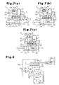
- a receiving member 51 is attached to the outer surface (the upper surface) of the injection cylinder 17 such that a drain port 51 a of the receiving member 51 communicates with the supply port 17k of the injection cylinder 17.
- the accumulator 22 is connected to the supply port 51 b of the receiving member 51.
- the receiving member 51 is mounted in a passage for supplying hydraulic fluid to the injection cylinder 17.
- a restriction member 52 is accommodated in a cylinder tube 51c of the receiving member 51 and has a restriction 52a.
- the restriction 52a is formed by cutting the peripheral surface of the restriction member 52 in an arcuate shape.
- the depth of the restriction 52a becomes gradually greater from the first axial end toward the second axial end of the restriction member 52 before becoming gradually smaller.
- the portion of the restriction member 52 close to the second axial end with respect to the restriction 52a is a block portion 52b for blocking the hydraulic fluid flowing from the supply port 51 b.
- a piston 53 is joined to the first end of the restriction member 52 in a manner movable integrally with the restriction member 52.
- the piston 53 is movably received in the receiving member 51.
- the piston 53 divides the interior of a first operation chamber 54a into a first operation chamber 54a at the side corresponding to the restriction member 52 and a second operation chamber 54b, which is located at the opposite side to the first operation chamber 54a.
- a supply-and-drain mechanism R for selectively supplying and draining hydraulic fluid is connected to the first operation chamber 54a and the second operation chamber 54b.
- the supply-and-drain mechanism R is configured by a hydraulic fluid tank 55, a pump 56 for pumping the hydraulic fluid out from the hydraulic fluid tank 55, and an electromagnetic switch valve 58 mounted in a hydraulic fluid passage 57 for connecting the first operation chamber 54a or the second operation chamber 54b to the pump 56.
- the electromagnetic switch valve 58 can be arranged at a first position 58a, at which the electromagnetic switch valve 58 permits supply of the hydraulic fluid pumped out of the hydraulic fluid tank 55 by the pump 56 to the first operation chamber 54a and drainage of the hydraulic fluid from the second operation chamber 54b to the hydraulic fluid tank 55.
- the electromagnetic switch valve 58 can also be arranged at a second position 58b, at which the electromagnetic switch valve 58 permits supply of the hydraulic fluid pumped out of the hydraulic fluid tank 55 by the pump 56 to the second operation chamber 54b and drainage of the hydraulic fluid from the first operation chamber 54a to the hydraulic fluid tank 55.
- the second-side portion of the restriction member 52 protrudes from the receiving member 51.
- An actuating member 50 which is joined to the second rod 17d, extends perpendicular to the second rod 17d. When the second rod 17d moves, the actuating member 50 presses the second end of the restriction member 52 to move the restriction member 52 into the receiving member 51.
- the restriction 52a As the restriction 52a continuously moves, the depth of the restriction 52a with respect to the supply port 51 b becomes gradually smaller and a part of the block portion 52b is moved to a position facing the supply port 51 b.
- the restriction 52a thus reduces the amount of the hydraulic fluid supplied from the accumulator 22 to the second chamber 17f. In other words, the flow rate of the hydraulic fluid is decreased. This decreases the hydraulic pressure applied to the piston 17c, thus reducing the speed of the piston 17c.
- the first rod 17a which is integral with the piston 17c, is also decelerated, and the injection plunger 16 is decelerated, too.
- the restriction member 52 in the pressure-increasing step after the high-speed step, the restriction member 52 is moved in the receiving member 51 by inertia of pressing of the actuating member 50 and the hydraulic pressure applied from the hydraulic fluid tank 55.
- the block portion 52b is thus arranged at the position facing the supply port 51 b. This causes the restriction member 52 to block the supply port 51 b.
- the supply passage of hydraulic fluid from the accumulator 22 is thus blocked by the block portion 52b, and flow of the hydraulic fluid is blocked.
- the second embodiment has the advantages described below in addition to the same advantages as the advantages (1) to (3) of the first embodiment.
- the block portion 52b is formed continuously with the restriction 52a in the axial direction of the restriction member 52. Accordingly, when reactive force is applied from the mold K to the piston 17c through the first rod 17a in the pressure-increasing step, the passage permitting communication between the first chamber 17e and the accumulator 22 is blocked by the block portion 52b of the restriction member 52. The piston 17c is thus stopped from being moved by the reactive force from the mold K.
- the supply-and-drain mechanism R is connected to the first operation chamber 54a and the second operation chamber 54b of the receiving member 51.
- the actuating member 50 which moves in conjunction with the second rod 17d, presses the restriction member 52, hydraulic fluid is supplied from the supply-and-drain mechanism R to the first operation chamber 54a to assist movement of the restriction member 52.
- This ensures movement of the restriction member 52 to cause the restriction 52a to restrict, or, in other words, decrease, the amount of the hydraulic fluid supplied from the accumulator 22.
- the injection cylinder 17 is thus reliably decelerated.
- the restriction member 44, 52 may be arranged close to the mold K when in the initial state. In this case, at the start of injection, the supply-and-drain mechanism T, R moves the restriction member 44, 52 such that the passage forming recess 44a or the restriction 52a is located at a position in the flow passage.
- a valve may be mounted between the injection cylinder 17 and the receiving member 42. In this case, operation of the injection cylinder 17 is selectively started and stopped by opening or closing the valve.
- a valve may be mounted between the accumulator 22 and the receiving member 51. In this case, operation of the injection cylinder 17 is selectively started and stopped by opening or closing the valve.
- the second rod 17d may include a joint mechanism that can be selectively joined to and separated from the second rod 17d.
- the second rod 17d is joined to the joint mechanism in an initial state but separated from the joint mechanism when the injection cylinder 17 is started to operate. In this manner, operation of the injection cylinder 17 is controlled to be started or suspended.
- the supply-and-drain mechanism R may be omitted.
- the restriction 52a may be formed as continuous recesses with different depths, as in the case of the first embodiment.
- the restriction may be formed in an arcuate shape as in the case of the second embodiment.
- the returning member 45 formed by a coil spring is employed to return the restriction member 44 to the position where the restriction member 44 is located before being moved.
- a hydraulic pressure circuit may be connected to the receiving member 42 to return the restriction member 44 by hydraulic fluid supply using the hydraulic pressure circuit.
- the injection apparatus 11 may be used in an injection apparatus that injects plastic material into the cavity 14 to mold a plastic product.
- the pilot rod 32a may be mechanically connected to the drive nut N1.
- the pilot rod 32a and the drive nut N1 may be an integral component.
Landscapes
- Engineering & Computer Science (AREA)
- Mechanical Engineering (AREA)
- Manufacturing & Machinery (AREA)
- Injection Moulding Of Plastics Or The Like (AREA)
- Moulds For Moulding Plastics Or The Like (AREA)
Abstract
Description
- The present invention relates to an injection apparatus that injects molding material into a mold through an injection cylinder actuated by fluid pressure of incompressible fluid, thus filling the mold with the molding material.
- Typically, an injection apparatus of a molding machine moves an injection plunger forward in a sleeve using an injection cylinder to press molding material (such as metal) out from the sleeve into a cavity formed between a pair of mold portions. The molding material is thus injected, or supplied, into the cavity. The injection, or supply, step includes a low-speed step, a high-speed step, and a pressure-increasing step.
- The injection apparatus reduces the speed of the injection cylinder, which moves at a high speed in the high-speed step and then proceeds to the pressure-increasing step. At this stage, if the injection cylinder is decelerated insufficiently, the injection plunger, which is integral with the injection cylinder, strikes the mold with impact, applying excessive pressure, which is surge pressure, to the cavity. To avoid such an excessive pressure, the injection apparatus includes a speed reduction mechanism for reducing the speed of the injection cylinder. See Patent Document 1.
- As shown in
Fig. 8 , in an injection apparatus disclosed in Patent Document 1, aninjection plunger 82 is connected to apiston rod 80a of aninjection cylinder 80 via acoupling 81. An L-shaped striker 83 is joined to thecoupling 81. Amagnetic scale 83a, which is formed by arranging magnetized portions and non-magnetized portions alternately at a constant interval, is attached to thestriker 83. Theinjection cylinder 80 is connected to a non-illustrated hydraulic fluid tank via afluid pressure circuit 80b. Thefluid pressure circuit 80b includes aflow control valve 80c, which is driven by apulse motor 80d. - The injection apparatus of Patent Document 1 also includes a
magnetic sensor 84 for detecting a magnetic signal of themagnetic scale 83a and aposition detector 85, which counts magnetic signals detected by themagnetic sensor 84 and converts the magnetic signals into a stroke signal of theinjection plunger 82. The injection apparatus further includes aspeed detector 86 for converting the stroke signal from theposition detector 85 into a speed signal and anacceleration detector 87 for converting the speed signals from thespeed detector 86 into an acceleration signal. - The injection apparatus also includes a
determination circuit 88 for detecting a time point at which speed reduction is started based on the acceleration signal, a valve openingdegree setting device 89 for setting the opening degree of theflow control valve 80c, aposition setting device 90 for changing injection speed, and acontrol command generator 91 for controlling theflow control valve 80c. - In the injection apparatus of Patent Document 1, the
striker 83 operates in conjunction with theinjection plunger 82 when the injection plunger 82 moves. Themagnetic sensor 84 detects a magnetic signal of themagnetic scale 83a, which is integral with thestriker 83. Then, based on signals from theposition detector 85, thespeed detector 86, theacceleration detector 87, thedetermination circuit 88, the valve openingdegree setting device 89, and theposition setting device 90, thecontrol command generator 91 outputs a control command to thepulse motor 80d. The opening degree of theflow control valve 80c is thus controlled to adjust the amount of the hydraulic fluid delivered from thefluid pressure circuit 80b into theinjection cylinder 80. In this manner, the movement speed of theinjection cylinder 80 is controlled to allow the aforementioned speed reduction to occur. - Patent Document 1: Japanese Laid-Open Patent Publication No.
60-76267 - However, in the injection apparatus of Patent Document 1, when the
magnetic sensor 84 detects movement of thestriker 83 and the time elapsing since such detection reaches the time point at which the speed of theinjection cylinder 80 should be reduced, speed reduction of theinjection cylinder 80 is started only after thedevices 85 to 90 input or output signals and then the opening degree of theflow control valve 80c is controlled. The injection apparatus of Patent Document 1 thus has a poor responsiveness after the time point for reducing the speed of theinjection cylinder 80. - Accordingly, it is an objective of the present invention to provide an injection apparatus capable of improving responsiveness after a time point at which the speed of an injection cylinder should be reduced.
- To achieve the foregoing objective and in accordance with one aspect of the present invention, an injection apparatus is provided that injects molding material into a mold through an injection cylinder operated by fluid pressure of an incompressible fluid to fill the mold with the molding material. The apparatus includes a pressure accumulating portion, which is connected to an operation chamber in the injection cylinder to accumulate the fluid pressure, a speed reduction mechanism for reducing the speed of the injection cylinder, and a passage for selectively supplying and draining the incompressible fluid to and from the injection cylinder. The injection cylinder includes a movable rod. The speed reduction mechanism includes an actuating member moving integrally with the rod of the injection cylinder, a restriction member mounted in the passage, and a receiving member for movably receiving the restriction member. The restriction member is movable in conjunction with movement of the actuating member and variably restricts the passage. The receiving member includes a supply port connected to the passage and a drain port communicating with the supply port. The restriction member has a restriction formed to restrict the passage to decrease the flow rate of the incompressible fluid from the supply port to the drain port.
- In this configuration, in an injection step, the actuating member moves integrally with the rod of the injection cylinder. At a time point for reducing the speed of the injection cylinder, the restriction member starts to move in the receiving member in conjunction with movement of the actuating member. As a result, the restriction of the restriction member restricts the passage of the incompressible fluid from the supply port to the drain port. When a supply passage for the incompressible fluid is restricted, the hydraulic pressure applied to the injection cylinder is reduced. If a drain passage for the incompressible fluid is restricted, the draining speed of the incompressible fluid is decreased. This reduces the speed of the injection cylinder. That is, by operating the restriction member in conjunction with the injection cylinder, the restriction member is operated synchronously with the injection cylinder such that restriction of the passage, or, in other words, speed reduction of the injection cylinder, is mechanically accomplished. This improves the responsiveness after the speed reducing time point compared with a case in which speed reduction of the injection cylinder is started after signal input or output by sensors and devices is completed and then valve opening control is carried out.
-
-
Fig. 1 is a diagram schematically showing an injection apparatus according to a first embodiment of the present invention; -
Fig. 2 is a diagram schematically showing a speed reduction mechanism of the injection apparatus illustrated inFig. 1 ; -
Fig. 3 is a graph representing changes of injection pressure and changes of injection speed in the injection apparatus; -
Fig. 4 is a diagram schematically illustrating a state in which an injection cylinder and a pilot cylinder operate; -
Fig. 5 is a diagram schematically showing a state in which the injection cylinder operates; -
Fig. 6 is a diagram schematically showing a state in which the speed reduction mechanism operates; -
Figs. 7(a), 7(b), and 7(c) are diagrams schematically showing a speed reduction mechanism of an injection apparatus according to a second embodiment of the invention; and -
Fig. 8 is a diagram schematically showing an injection apparatus of the background art. - An injection apparatus according to a first embodiment of the present invention will now be described with reference to
Figs. 1 to 6 . In the description below, the left side and the right side of each drawing are defined as the first side and the second side, respectively. Similarly, the left end and the right end of each component are defined as the first end and the second end, respectively. - As shown in
Fig. 1 , a mold K includes a fixedmold portion 12 and amovable mold portion 13. The fixedmold portion 12 and themovable mold portion 13 are joined together, separated from each other, or clamped by a non-illustrated mold clamping device. Aninjection apparatus 11 injects, or supplies, metal material serving as molding material into acavity 14, which is formed in the mold K. After having been injected into and solidified in the mold K, the metal material is removed from the mold K as a desired molded product. - The fixed
mold portion 12 has aninjection sleeve 15 communicating with thecavity 14. Aninjection plunger 16 is slidably mounted in theinjection sleeve 15. Theinjection plunger 16 is connected to afirst rod 17a, which is one of the rods of a double-rodtype injection cylinder 17. Apiston 17c, which is integral with thefirst rod 17a, is movably received in acylinder tube 17b of theinjection cylinder 17. Asecond rod 17d is formed integrally with thepiston 17c at the side of thepiston 17c opposite to thefirst rod 17a. Thepiston 17c divides the interior of thecylinder tube 17b into afirst chamber 17e serving as an operation chamber located at the side corresponding to thefirst rod 17a and asecond chamber 17f serving as an operation chamber arranged at the opposite side, which is the side corresponding to thesecond rod 17d. - With reference to
Fig. 2 , thecylinder tube 17b of theinjection cylinder 17 has asupply port 17k communicating with thesecond chamber 17f. Anaccumulator 22 serving as a pressure accumulating portion is connected to thesupply port 17k. Theaccumulator 22 stores hydraulic fluid serving as incompressible fluid. The hydraulic fluid is supplied from theaccumulator 22 into thesecond chamber 17f through thesupply port 17k. Hydraulic pressure, which is fluid pressure, is thus applied to thepiston 17c in the direction toward the mold K, allowing thefirst rod 17a and thesecond rod 17d to move toward the mold K. Thecylinder tube 17b has a drain port 17g, which communicates with thefirst chamber 17e. - As shown in
Fig. 1 , a control unit S is mechanically joined to thesecond rod 17d of theinjection cylinder 17. Specifically, the first end of arotary shaft 24, which is configured by a ball screw, is connected to the distal end of thesecond rod 17d through a joint 23. The joint 23 supports therotary shaft 24 to thesecond rod 17d in a manner allowing therotary shaft 24 to rotate relative to thesecond rod 17d. Anut 25 is threaded onto therotary shaft 24. Thenut 25 is fixed to a housing (not shown) of theinjection apparatus 11 immovably and non-rotationally. As a result, when thesecond rod 17d proceeds or retreats, therotary shaft 24 axially proceeds or retreats and rotates relative to thenut 25. - A
brake disk 26 serving as a rotation member is connected to therotary shaft 24 at the second end of therotary shaft 24 in a manner rotational integrally with therotary shaft 24. A first brake pad 27a and asecond brake pad 27b are arranged opposed to each other at the front side and the rear side, respectively, in the direction of the thickness of thebrake disk 26. The first brake pad 27a and thesecond brake pad 27b are movable in conjunction with each other toward or away from thebrake disk 26. When the first andsecond brake pads 27a, 27b are pressed against thebrake disk 26, the first andsecond brake pads 27a, 27b slide on therotating brake disk 26 and generate friction resistance to thebrake disk 26. - The distal end of an
actuating rod 30a of anactuating cylinder 30 is joined to thesecond brake pad 27b. Acylinder tube 30b of theactuating cylinder 30 receives a piston 30c, which is integral with theactuating rod 30a. The piston 30c divides the interior of thecylinder tube 30b into afirst rod chamber 30d located at the side corresponding to theactuating rod 30a and afirst head chamber 30e arranged at the opposite side to theactuating rod 30a. - A
pilot cylinder 32 is connected to theactuating cylinder 30 through a first fluid supply-and-drain passage 31 a and a second fluid supply-and-drain passage 31 b. Apiston 32c is accommodated in acylinder tube 32b of thepilot cylinder 32. Apilot rod 32a is formed integrally with thepiston 32c. Thepiston 32c divides the interior of thecylinder tube 32b into asecond rod chamber 32d at the side corresponding to thepilot rod 32a and asecond head chamber 32e at the opposite side to thepilot rod 32a. - The
first rod chamber 30d of theactuating cylinder 30 is connected to thesecond rod chamber 32d of thepilot cylinder 32 through the first fluid supply-and-drain passage 31 a. Thefirst head chamber 30e of theactuating cylinder 30 is connected to thesecond head chamber 32e of thepilot cylinder 32 through the second fluid supply-and-drain passage 31 b. Hydraulic fluid serving as incompressible fluid is retained in thefirst rod chamber 30d and thesecond rod chamber 32d and in thefirst head chamber 30e and thesecond head chamber 32e. The first and second fluid supply-and-drain passages - The diameter of the
actuating cylinder 30 is greater than the diameter of thepilot cylinder 32. An amplification circuit for amplifying the thrust force of theactuating rod 30a in theactuating cylinder 30 is configured by the difference in diameter between the actuatingcylinder 30 and thepilot cylinder 32 and using the first and second fluid supply-and-drain passages - The distal end of the
pilot rod 32a is selectively brought into contact with and separated from a drive nut N1. The drive nut N1 is threaded onto a drive ball screw B1. The drive ball screw B2 is driven by a drive motor M1 to rotate in forward and reverse directions. When the drive motor M1 rotates, the drive ball screw B1 rotates at the same speed as the rotation speed of the drive motor M1. The drive nut N1, which is threaded onto the drive ball screw B1, moves at the speed corresponding to the rotation speed of the drive ball screw B1. - When the drive ball screw B1 rotates in a certain direction, the drive nut N1 proceeds (linearly moves) in the axial direction of the drive ball screw B1 and the
pilot rod 32a proceeds in conjunction with the drive nut N1. This drains the hydraulic fluid from thesecond rod chamber 32d to thefirst rod chamber 30d through the first fluid supply-and-drain passage 31 a and from thefirst head chamber 30e into thesecond head chamber 32e via the second fluid supply-and-drain passage 31 b. As a result, thesecond brake pad 27b, which is integral with theactuating rod 30a, is separated from thebrake disk 26. - In the first embodiment, the
brake disk 26, the first brake pad 27a, thesecond brake pad 27b, theactuating cylinder 30, the first and second fluid supply-and-drain passages pilot cylinder 32 are accommodated in a housing H to form a unit. In the housing H, therotary shaft 24, thebrake disk 26, theactuating cylinder 30, the first brake pad 27a, thesecond brake pad 27b, and thepilot cylinder 32 are accommodated as an integral body, which is a brake unit BU. The brake unit BU is received in the housing H to be movable in the forward-rearward direction. - Actuation patterns (injection patterns) of the
injection apparatus 11 will hereafter be described with reference toFig. 3 . - The
injection apparatus 11 operates according to a low-speed step, a high-speed step, and a pressure-increasing step. The low-speed step is a step at an initial stage of injection. In the low-speed step, theinjection plunger 16 is actuated to inject metal material from theinjection sleeve 15 into thecavity 14. - The high-speed step is performed after the low-speed step. In the high-speed step, the
injection plunger 16 of theinjection sleeve 15 is actuated at a high speed compared with the low-speed step. At a later stage of the high-speed step, theinjection plunger 16 is gradually decelerated. When the speed of theinjection plunger 16 approximates zero, theinjection apparatus 11 starts the pressure-increasing step. The pressure-increasing step is a step at a final stage of injection and carried out after the high-speed step. In the pressure-increasing step, the metal material in thecavity 14 is pressurized using the force generated by theinjection plunger 16 of theinjection sleeve 15 in the direction proceeding toward the mold K. - Referring to
Fig. 3 , theinjection apparatus 11 is required to operate in different actuation patterns in the steps. In other words, in the substantially entire period of the high-speed step, theinjection plunger 16 must operate at a high speed compared with the low-speed step. In contrast, theinjection plunger 16 does not have to operate rapidly in the pressure-increasing step. In the pressure-increasing step, theinjection plunger 16 must operate to produce high pressure compared with the low-speed step and high-speed step. In contrast, theinjection plunger 16 does not have to operate to produce high pressure in the low-speed and high-speed steps, compared with the pressure-increasing step. - A speed reduction mechanism G of the first embodiment will hereafter be described.
- As illustrated in
Fig. 2 , an L-shapedactuating member 41 is joined to thesecond rod 17d of theinjection cylinder 17 in a manner rotational integrally with thesecond rod 17d. Specifically, ajoint portion 41 a, which extends perpendicular to the axial direction of thesecond rod 17d, connects the actuatingmember 41 to thesecond rod 17d. The actuatingmember 41 has anarm 41 b, which projects perpendicular to thejoint portion 41 a and extends in the axial direction of thesecond rod 17d. - A receiving
member 42 is attached to the outer surface (the lower surface as viewed inFig. 1 ) of theinjection cylinder 17. The receivingmember 42 includes acylinder tube 42a, which has asupply port 42b. Thesupply port 42b communicates with the drain port 17g of theinjection cylinder 17. The hydraulic fluid drained from thefirst chamber 17e of theinjection cylinder 17 flows into the receivingmember 42 via the drain port 17g and thesupply port 42b. Thecylinder tube 42a also includes adrain port 42c, which is formed at the position facing thesupply port 42b. The hydraulic fluid introduced from theinjection cylinder 17 into the receivingmember 42 is drained from the receivingmember 42 via thedrain port 42c. That is, the receivingmember 42 is arranged in the drainage path of the hydraulic fluid with respect to theinjection cylinder 17. - In the receiving
member 42, alid member 43 is joined to and closes the first end of thecylinder tube 42a. The second end of thecylinder tube 42a is open. Thecylinder tube 42a receives a columnarmovable restriction member 44, which variably restricts the passage. A returningmember 45 formed by a coil spring is mounted between the first end of therestriction member 44 and thelid member 43. The returningmember 45 urges therestriction member 44 toward the second side of thecylinder tube 42a. When therestriction member 44 is pressed toward the mold K against the returningmember 45, the returningmember 45 is compressed to move therestriction member 44 toward the mold K by the amount corresponding to the compressed amount of the returningmember 45. In contrast, by releasing therestriction member 44, the returningmember 45 is returned from the compressed state to its original state, thus generating force to move therestriction member 44 away from the mold K. - A second-side portion of the
restriction member 44 protrudes from the second end of thecylinder tube 42a. A passage forming recess 44a, through which hydraulic fluid flows from thesupply port 42b to thedrain port 42c, is formed in a peripheral surface of therestriction member 44 by recessing a portion of therestriction member 44 along the axis. When the passage forming recess 44a is arranged between thesupply port 42b and thedrain port 42c, the hydraulic fluid introduced into the receivingmember 42 through thesupply port 42b flows in the passage forming recess 44a and is thus drained from the receivingmember 42 through thedrain port 42c. The cross-sectional area of the passage forming recess 44a in the axial direction of therestriction member 44 is equal to both the cross-sectional area of thesupply port 42b and the cross-sectional area of thedrain port 42c. This allows the hydraulic fluid to flow from thesupply port 42b to thedrain port 42c through the passage forming recess 44a without being restricted by the passage forming recess 44a. - A
restriction forming recess 44b serving as a restriction is formed in the peripheral surface of therestriction member 44 at a position close to the second end along the axis compared with the position of the passage forming recess 44a. The depth of therestriction forming recess 44b is smaller than the depth of the passage forming recess 44a. When therestriction forming recess 44b is located between thesupply port 42b and thedrain port 42c, the hydraulic fluid introduced into the receivingmember 42 via thesupply port 42b flows in therestriction forming recess 44b and is thus drained from the receivingmember 42 through thedrain port 42c. - The cross-sectional area (the cross-sectional area for the hydraulic fluid) of the
restriction forming recess 44b in the axial direction of therestriction member 44 is smaller than both the cross-sectional area of thesupply port 42b and the cross-sectional area of thedrain port 42c and smaller than the cross-sectional area of the passage forming recess 44a. Therestriction forming recess 44b thus restricts the hydraulic fluid when the hydraulic fluid flows from thesupply port 42b to thedrain port 42c through the passage forming recess 44a. - The
restriction member 44 is arranged such that the passage forming recess 44a faces thesupply port 42b and thedrain port 42c when therestriction member 44 is urged toward the second side of thecylinder tube 42a by the returningmember 45 without being pressed toward the mold K. Therestriction forming recess 44b is close to the second side of thecylinder tube 42a compared with thesupply port 42b and thedrain port 42c. - In the high-speed step, the distal end of the
arm 41b of the actuatingmember 41 contacts the second end of therestriction member 44 at the time point for starting speed reduction (at time point T3 inFig. 3 ). When thepiston 17c and thesecond rod 17d are moved by the hydraulic pressure applied by theaccumulator 22, the actuatingmember 41 is moved in conjunction with thesecond rod 17d. Such movement of the actuatingmember 41 presses therestriction member 44 toward the returningmember 45, thus moving therestriction member 44 toward the first side of thecylinder tube 42a (toward the mold K). In other words, the length of thearm 41b of the actuatingmember 41, the urging force of the returningmember 45, and the length of therestriction member 44 are adjusted such that thearm 41 b of the actuatingmember 41 comes into contact with therestriction member 44 at the time point for starting speed reduction (at time point T3). That is, therestriction member 44 is allowed to move in conjunction with the actuatingmember 41 after having been brought into contact with the actuatingmember 41. - With reference to
Fig. 2 , a supply-and-drain mechanism T is connected to thedrain port 42c of thecylinder tube 42a. The supply-and-drain mechanism T supplies hydraulic fluid to thefirst chamber 17e and drains the hydraulic fluid from thefirst chamber 17e through the receivingmember 42. The supply-and-drain mechanism T is configured by ahydraulic fluid tank 18, apump 19 for pumping hydraulic fluid out from thehydraulic fluid tank 18, and anelectromagnetic switch valve 21, which is mounted in ahydraulic fluid passage 20 connecting thefirst chamber 17e to thepump 19. Theelectromagnetic switch valve 21 is switchable between afirst position 21 a and asecond position 21 b. When arranged at thefirst position 21 a, theelectromagnetic switch valve 21 permits the hydraulic fluid pumped out of thehydraulic fluid tank 18 by thepump 19 to be supplied to thefirst chamber 17e. When arranged at thesecond position 21 b, theelectromagnetic switch valve 21 permits the hydraulic fluid to be drained from thefirst chamber 17e into thehydraulic fluid tank 18. - Operation of the
injection apparatus 11 of the first embodiment will now be described. - The low-speed step will first be described.
- As shown in
Fig. 1 , before the low-speed step is started, theinjection plunger 16 of theinjection sleeve 15, thefirst rod 17a and thesecond rod 17d of theinjection cylinder 17, theactuating rod 30a of theactuating cylinder 30, and thepilot rod 32a of thepilot cylinder 32 are arranged at predetermined initial positions, which are illustrated in the drawing. Therods Fig. 3 ). - At this stage, the
electromagnetic switch valve 21 is arranged at thefirst position 21 a to stop the hydraulic fluid in thefirst chamber 17e of theinjection cylinder 17 from returning to thehydraulic fluid tank 18. Thesecond chamber 17f receives the hydraulic fluid from theaccumulator 22. Thepiston 17c receives, as hydraulic pressure, energy necessary for generating thrust force for theinjection plunger 16. - When located at the initial positions, the drive motor M1 is not operated and the drive nut N1 is stopped. The
pilot rod 32a of thepilot cylinder 32 is pressed against the drive nut N1. The hydraulic pressure applied by thepilot cylinder 32 is amplified by the amplification circuit and then applied to the piston 30c of theactuating cylinder 30. The amplified hydraulic pressure presses thesecond brake pad 27b, which is integral with theactuating rod 30a, against thebrake disk 26 and presses the first brake pad 27a against thebrake disk 26 in conjunction with thesecond brake pad 27b. The brake unit BU thus restricts rotation of thebrake disk 26 and rotation of therotary shaft 24, which is integral with thebrake disk 26. - As a result, movement of the
second rod 17d, which is integral with therotary shaft 24, is restricted. Movement of thepiston 17c of theinjection cylinder 17, which is in a state movable by the hydraulic pressure from theaccumulator 22, is restricted by thesecond rod 17d. That is, thepiston 17c is prohibited from moving. Specifically, since the hydraulic pressure from theaccumulator 22 acts on thepiston 17c, thepiston 17c is held in a standby state where thepiston 17c can move immediately when permitted. - Referring to
Fig. 2 , in the speed reduction mechanism G, therestriction member 44 is urged toward the second end of thecylinder tube 42a by the returningmember 45 without being pressed toward the mold K. Therestriction member 44 is thus arranged in the speed reduction mechanism G such that the passage forming recess 44a faces thesupply port 42b and thedrain port 42c. - After preparation including clamping of the fixed
mold portion 12 and themovable mold portion 13 and metal material supply to theinjection sleeve 15 is completed, theinjection apparatus 11 initiates the low-speed step. In the low-speed step, thefirst rod 17a of the injection cylinder 17 (the injection plunger 16) moves at an injection speed V1, as represented inFig. 3 . At the same time, theelectromagnetic switch valve 21 is switched to thesecond position 21 b. - As illustrated in
Fig. 4 , when the drive motor M1 is activated, the drive ball screw B1 rotates to cause the drive nut N1 to proceed. This temporarily separates thepilot rod 32a of thepilot cylinder 32, which has been pressed against the drive nut N1, from the drive nut N1. Thepilot rod 32a then proceeds together with the drive nut N1. - As the
pilot rod 32a proceeds, the hydraulic fluid in thesecond rod chamber 32d is drained to thefirst rod chamber 30d through the first fluid supply-and-drain passage 31 a, and the hydraulic fluid in thefirst head chamber 30e is introduced into thesecond head chamber 32e through the second fluid supply-and-drain passage 31 b. Theactuating rod 30a is thus retracted into thecylinder tube 30b, thus separating thesecond brake pad 27b, which is integral with theactuating rod 30a, from thebrake disk 26. The first brake pad 27a is also separated from thebrake disk 26, in conjunction with thesecond brake pad 27b. At this stage, thefirst rod 17a and thesecond rod 17d slowly proceed and thebrake disk 26 and therotary shaft 24 slowly rotate. - As a result, with reference to
Fig. 5 , thepiston 17c, movement of which has been restricted by the brake unit BU, receives the hydraulic pressure from theaccumulator 22 and thus proceeds toward thefirst chamber 17e at the aforementioned injection speed V1. This causes thefirst rod 17a, which is integral with thepiston 17c, to proceed at the injection speed V1. As a result, theinjection plunger 16, which is joined to thefirst rod 17a, to proceed toward thecavity 14 at the injection speed V1. This injects the metal material from theinjection sleeve 15 into thecavity 14. - Simultaneously, the hydraulic fluid in the
first chamber 17e is drained from theinjection cylinder 17 via the drain port 17g and introduced into the receivingmember 42 through thesupply port 42b. At this stage, therestriction member 44 is not pressed by the actuatingmember 41. The hydraulic fluid thus flows in the passage forming recess 44a of therestriction member 44 and is thus drained from the receivingmember 42 through thedrain port 42c without being restricted by the passage forming recess 44a. Afterwards, the hydraulic fluid is drained to thehydraulic fluid tank 18 through theelectromagnetic switch valve 21, which is held at thesecond position 21 b. - Also, the brake unit BU, which is connected to the
injection plunger 16 via thefirst rod 17a, thesecond rod 17d, and therotary shaft 24, proceeds to cause theinjection plunger 16 to proceed. When theinjection plunger 16 reaches the final position of the low-speed step (at time point T2 inFig. 3 ), theinjection apparatus 11 ends the low-speed step and starts the high-speed step. In the high-speed step, theinjection plunger 16 moves at an injection speed V2, as represented inFig. 3 . - The
injection apparatus 11 then operates in the above-described manner to carry out the high-speed step. In the high-speed step, thefirst rod 17a and thesecond rod 17d proceed at a high speed and thebrake disk 26 and therotary shaft 24 rotate at a high speed. At the time point for reducing the speed of theinjection plunger 16 in the high-speed step (at time point T3 inFig. 3 ), the speed reduction mechanism G is activated. - As illustrated in
Fig. 6 , when thesecond rod 17d proceeds, the actuatingmember 41, which is integral with thesecond rod 17d, also proceeds, or moves, to cause thearm 41b of the actuatingmember 41 to contact the second end of therestriction member 44. As thesecond rod 17d continuously proceeds, or moves, the actuatingmember 41 is caused to press therestriction member 44. This moves therestriction member 44 in conjunction with movement of the actuatingmember 41 toward the mold K against the urging force of the returningmember 45. As a result, therestriction forming recess 44b is moved to the position facing thesupply port 42b and thedrain port 42c in therestriction member 44, at which the passage forming recess 44a has been located. - In this state, the hydraulic fluid drained from the
first chamber 17e is thus delivered from thesupply port 42b of the receivingmember 42 into therestriction forming recess 44b in the receivingmember 42. This restricts the amount of the hydraulic fluid drained from thefirst chamber 17e, or, in other words, decreases the flow rate of the hydraulic fluid. As a result, the amount of the hydraulic fluid drained from the receivingmember 42 through thedrain port 42c of the receivingmember 42 is reduced, and the speed of thepiston 17c is reduced. The speed of thefirst rod 17a, which is integral with thepiston 17c, is thus also reduced such that the speed of theinjection plunger 16 is reduced. After having been drained from the receivingmember 42, the hydraulic fluid is drained to thehydraulic fluid tank 18 through theelectromagnetic switch valve 21, which is maintained at thesecond position 21 b. - Then, when the
injection plunger 16 reaches a position at which theinjection plunger 16 should proceed in the high-speed step (at time point T4 inFig. 3 ), theinjection apparatus 11 ends the high-speed step and carries out the pressure-increasing step. - In the pressure-increasing step, pressure applied by the
injection plunger 16 reaches an injection pressure P, as represented inFig. 3 . Then, theinjection apparatus 11 operates in the above-described manner and starts the pressure-increasing step. In the pressure-increasing step, thepilot rod 32a does not contact the drive nut N1. The hydraulic pressure from theaccumulator 22 is thus applied to theinjection plunger 16 via thefirst rod 17a. - Afterwards, when the metal material in the
cavity 14 is solidified, thefirst rod 17a of theinjection cylinder 17 is caused to recede. At this stage, theelectromagnetic switch valve 21 is switched to thefirst position 21 a. This drives thepump 19 to supply the hydraulic fluid pumped by thepump 19 to thefirst chamber 17e of theinjection cylinder 17. Thefirst rod 17a of theinjection cylinder 17 thus recedes and theinjection plunger 16 also recedes. This returns the hydraulic fluid from thesecond chamber 17f into theaccumulator 22. Thesecond rod 17d also recedes to cause the urging force of the returningmember 45 to return therestriction member 44 to the original position where therestriction member 44 was located before being pressed by the actuatingmember 41. In other words, therestriction member 44 is returned to such a position that the passage forming recess 44a of therestriction member 44 faces thesupply port 42b and thedrain port 42c. Afterwards, the fixedmold portion 12 and themovable mold portion 13 are separated from each other, and the molded product is removed from the mold K. - The first embodiment has the advantages described below.
- (1) In the
injection apparatus 11, the actuatingmember 41 is connected to thesecond rod 17d of theinjection cylinder 17 in a manner movable integrally with thesecond rod 17d. The receivingmember 42 is mounted in the drain passage of hydraulic fluid from theinjection cylinder 17. The hydraulic fluid drained from theinjection cylinder 17 flows in the receivingmember 42. Therestriction member 44 is arranged in the receivingmember 42 to restrict the passage of the hydraulic fluid. Therestriction member 44 is moved in conjunction with the actuatingmember 41, which moves integrally with theinjection cylinder 17, such that the amount of the hydraulic fluid drained from theinjection cylinder 17 is reduced by therestriction forming recess 44b of therestriction member 44. In other words, by moving therestriction member 44 in conjunction with theinjection cylinder 17, therestriction member 44 is operated synchronously with theinjection cylinder 17 and the passage is restricted mechanically. Therestriction member 44 is thus mechanically operated at the time point for reducing the speed of the injection cylinder 17 (at time point T3) to decelerate theinjection cylinder 17. This improves response after the speed reduction time point compared with a case in which speed reduction of theinjection cylinder 17 is started only after signal input or output by sensors and devices is accomplished and valve opening control is achieved. Additionally, the aforementioned time point is adjusted accurately and reliably. - (2) By moving the
restriction member 44 in conjunction with the actuatingmember 41, which moves integrally with theinjection cylinder 17, the movement speed of theinjection cylinder 17 is mechanically decreased in a manner synchronous with movement of theinjection cylinder 17. This makes it unnecessary to employ a flow control valve, a motor for driving the flow control valve, and various signal input or output devices to decelerate theinjection cylinder 17. The configuration of theinjection apparatus 11 is thus simplified. - (3) In the high-speed step, the
restriction member 44 starts to move at the time point for speed reduction (at time point T3) to move therestriction forming recess 44b to the position facing thesupply port 42b, at which the passage forming recess 44a has been located. This rapidly decreases the cross-sectional area of the hydraulic fluid passage, thus quickly decreasing the movement speed of theinjection cylinder 17. - (4) The receiving
member 42 is joined to theinjection cylinder 17. Thesupply port 42b of the receivingmember 42 is connected to the drain port 17g of theinjection cylinder 17. Therestriction member 44 is movably received in the receivingmember 42. This arrangement forms a passage of hydraulic fluid in the receivingmember 42. The passage is restricted by therestriction forming recess 44b of therestriction member 44, which operates in conjunction with the actuatingmember 41. This ensures a simple configuration for restricting the hydraulic fluid passage from theinjection cylinder 17 to decelerate theinjection cylinder 17. - (5) The returning
member 45 is mounted in the receivingmember 42 to return therestriction member 44 to the state before therestriction member 44 is pressed by the actuatingmember 41. This simplifies operation of theinjection apparatus 11 compared with a case in which therestriction member 44 is manually returned after theinjection cylinder 17 is caused to recede. - A second embodiment of the present invention will now be described with reference to
Fig. 7 . The same components in the second embodiment as those in the first embodiment are given the same reference numerals and description thereof is omitted. - As illustrated in
Figs. 7(a) to 7(c) , in the speed reduction mechanism G, a receivingmember 51 is attached to the outer surface (the upper surface) of theinjection cylinder 17 such that adrain port 51 a of the receivingmember 51 communicates with thesupply port 17k of theinjection cylinder 17. Theaccumulator 22 is connected to thesupply port 51 b of the receivingmember 51. In other words, the receivingmember 51 is mounted in a passage for supplying hydraulic fluid to theinjection cylinder 17. Arestriction member 52 is accommodated in acylinder tube 51c of the receivingmember 51 and has arestriction 52a. Therestriction 52a is formed by cutting the peripheral surface of therestriction member 52 in an arcuate shape. That is, the depth of therestriction 52a becomes gradually greater from the first axial end toward the second axial end of therestriction member 52 before becoming gradually smaller. The portion of therestriction member 52 close to the second axial end with respect to therestriction 52a is ablock portion 52b for blocking the hydraulic fluid flowing from thesupply port 51 b. - In the receiving
member 51, apiston 53 is joined to the first end of therestriction member 52 in a manner movable integrally with therestriction member 52. Thepiston 53 is movably received in the receivingmember 51. Thepiston 53 divides the interior of afirst operation chamber 54a into afirst operation chamber 54a at the side corresponding to therestriction member 52 and asecond operation chamber 54b, which is located at the opposite side to thefirst operation chamber 54a. A supply-and-drain mechanism R for selectively supplying and draining hydraulic fluid is connected to thefirst operation chamber 54a and thesecond operation chamber 54b. The supply-and-drain mechanism R is configured by ahydraulic fluid tank 55, apump 56 for pumping the hydraulic fluid out from thehydraulic fluid tank 55, and anelectromagnetic switch valve 58 mounted in ahydraulic fluid passage 57 for connecting thefirst operation chamber 54a or thesecond operation chamber 54b to thepump 56. - The
electromagnetic switch valve 58 can be arranged at a first position 58a, at which theelectromagnetic switch valve 58 permits supply of the hydraulic fluid pumped out of thehydraulic fluid tank 55 by thepump 56 to thefirst operation chamber 54a and drainage of the hydraulic fluid from thesecond operation chamber 54b to thehydraulic fluid tank 55. Theelectromagnetic switch valve 58 can also be arranged at a second position 58b, at which theelectromagnetic switch valve 58 permits supply of the hydraulic fluid pumped out of thehydraulic fluid tank 55 by thepump 56 to thesecond operation chamber 54b and drainage of the hydraulic fluid from thefirst operation chamber 54a to thehydraulic fluid tank 55. - The second-side portion of the
restriction member 52 protrudes from the receivingmember 51. An actuatingmember 50, which is joined to thesecond rod 17d, extends perpendicular to thesecond rod 17d. When thesecond rod 17d moves, the actuatingmember 50 presses the second end of therestriction member 52 to move therestriction member 52 into the receivingmember 51. - As illustrated in
Fig. 7(a) , when theinjection apparatus 11 is arranged at the initial position, therestriction member 52 is not pressed by the actuatingmember 50 and therestriction 52a as a whole is arranged to face thedrain port 51 a and thesupply port 51 b. Theelectromagnetic switch valve 58 of the supply-and-drain mechanism R is located at the first position 58a. At the time point for speed reduction in the high-speed step, referring toFig. 7(b) , the actuatingmember 50 is caused to press therestriction member 52. In this state, hydraulic fluid is delivered from thehydraulic fluid tank 55 of the supply-and-drain mechanism R into thefirst operation chamber 54a and hydraulic pressure is applied to thepiston 53 of therestriction member 52. The hydraulic pressure thus assists movement of therestriction member 52. - As the
restriction 52a continuously moves, the depth of therestriction 52a with respect to thesupply port 51 b becomes gradually smaller and a part of theblock portion 52b is moved to a position facing thesupply port 51 b. Therestriction 52a thus reduces the amount of the hydraulic fluid supplied from theaccumulator 22 to thesecond chamber 17f. In other words, the flow rate of the hydraulic fluid is decreased. This decreases the hydraulic pressure applied to thepiston 17c, thus reducing the speed of thepiston 17c. As a result, thefirst rod 17a, which is integral with thepiston 17c, is also decelerated, and theinjection plunger 16 is decelerated, too. - With reference to
Fig. 7(c) , in the pressure-increasing step after the high-speed step, therestriction member 52 is moved in the receivingmember 51 by inertia of pressing of the actuatingmember 50 and the hydraulic pressure applied from thehydraulic fluid tank 55. Theblock portion 52b is thus arranged at the position facing thesupply port 51 b. This causes therestriction member 52 to block thesupply port 51 b. The supply passage of hydraulic fluid from theaccumulator 22 is thus blocked by theblock portion 52b, and flow of the hydraulic fluid is blocked. - Accordingly, the second embodiment has the advantages described below in addition to the same advantages as the advantages (1) to (3) of the first embodiment.
- (6) The
block portion 52b is formed continuously with therestriction 52a in the axial direction of therestriction member 52. Accordingly, when reactive force is applied from the mold K to thepiston 17c through thefirst rod 17a in the pressure-increasing step, the passage permitting communication between thefirst chamber 17e and theaccumulator 22 is blocked by theblock portion 52b of therestriction member 52. Thepiston 17c is thus stopped from being moved by the reactive force from the mold K. - (7) The supply-and-drain mechanism R is connected to the
first operation chamber 54a and thesecond operation chamber 54b of the receivingmember 51. When the actuatingmember 50, which moves in conjunction with thesecond rod 17d, presses therestriction member 52, hydraulic fluid is supplied from the supply-and-drain mechanism R to thefirst operation chamber 54a to assist movement of therestriction member 52. This ensures movement of therestriction member 52 to cause therestriction 52a to restrict, or, in other words, decrease, the amount of the hydraulic fluid supplied from theaccumulator 22. Theinjection cylinder 17 is thus reliably decelerated. - The illustrated embodiments may be modified to the forms described below.
- In each of the first and second embodiments, the
restriction member restriction member restriction 52a is located at a position in the flow passage. - In the first embodiment, a valve may be mounted between the
injection cylinder 17 and the receivingmember 42. In this case, operation of theinjection cylinder 17 is selectively started and stopped by opening or closing the valve. - In the second embodiment, a valve may be mounted between the
accumulator 22 and the receivingmember 51. In this case, operation of theinjection cylinder 17 is selectively started and stopped by opening or closing the valve. - In the first and second embodiments, the
second rod 17d may include a joint mechanism that can be selectively joined to and separated from thesecond rod 17d. In this case, thesecond rod 17d is joined to the joint mechanism in an initial state but separated from the joint mechanism when theinjection cylinder 17 is started to operate. In this manner, operation of theinjection cylinder 17 is controlled to be started or suspended. - In the second embodiment, the supply-and-drain mechanism R may be omitted.
- In the second embodiment, the
restriction 52a may be formed as continuous recesses with different depths, as in the case of the first embodiment. - In the first embodiment, the restriction may be formed in an arcuate shape as in the case of the second embodiment.
- In the first embodiment, the returning
member 45 formed by a coil spring is employed to return therestriction member 44 to the position where therestriction member 44 is located before being moved. However, a hydraulic pressure circuit may be connected to the receivingmember 42 to return therestriction member 44 by hydraulic fluid supply using the hydraulic pressure circuit. - The
injection apparatus 11 may be used in an injection apparatus that injects plastic material into thecavity 14 to mold a plastic product. - The
pilot rod 32a may be mechanically connected to the drive nut N1. Alternatively, thepilot rod 32a and the drive nut N1 may be an integral component.
Claims (5)
- An injection apparatus that injects molding material into a mold through an injection cylinder operated by fluid pressure of an incompressible fluid to fill the mold with the molding material, the apparatus comprising:a pressure accumulating portion, which is connected to an operation chamber in the injection cylinder to accumulate the fluid pressure;a speed reduction mechanism for reducing the speed of the injection cylinder; anda passage for selectively supplying and draining the incompressible fluid to and from the injection cylinder, whereinthe injection cylinder includes a movable rod,the speed reduction mechanism includes
an actuating member moving integrally with the rod of the injection cylinder, a restriction member mounted in the passage, the restriction member being movable in conjunction with movement of the actuating member, the restriction member variably restricting the passage, and
a receiving member for movably receiving the restriction member,the receiving member includes a supply port connected to the passage and a drain port communicating with the supply port, andthe restriction member has a restriction formed to restrict the passage to decrease the flow rate of the incompressible fluid from the supply port to the drain port. - The injection apparatus according to claim 1, further comprising a block portion that is formed in the restriction member, wherein the block portion blocks flow of the incompressible fluid by closing the passage.
- The injection apparatus according to claim 1 or 2, wherein
the restriction member is movable in conjunction with the actuating member while being held in contact with the actuating member,
the restriction member is arranged in either a state before the restriction member is allowed to operate in conjunction with the actuating member or a state after the restriction member is allowed to operate in conjunction with the actuating member, and
the injection apparatus further comprises a returning member arranged in the receiving member to return the restriction member to a position where the restriction member is located before being moved. - The injection apparatus according to any one of claims 1 to 3, further comprising a supply-and-drain mechanism that is connected to the receiving member and selectively supplies and drains the incompressible fluid to move the restriction member.
- The injection apparatus according to any one of claims 1 to 4, wherein, when the passage is restricted by the restriction, the cross-sectional area of the passage for the incompressible fluid is smaller than both the cross-sectional area of the supply port and the cross-sectional area of the drain port.
Applications Claiming Priority (2)
| Application Number | Priority Date | Filing Date | Title |
|---|---|---|---|
| JP2011230017A JP5673482B2 (en) | 2011-10-19 | 2011-10-19 | Injection device |
| PCT/JP2012/075522 WO2013058101A1 (en) | 2011-10-19 | 2012-10-02 | Injection apparatus |
Publications (3)
| Publication Number | Publication Date |
|---|---|
| EP2769819A1 true EP2769819A1 (en) | 2014-08-27 |
| EP2769819A4 EP2769819A4 (en) | 2015-06-24 |
| EP2769819B1 EP2769819B1 (en) | 2016-12-07 |
Family
ID=48140753
Family Applications (1)
| Application Number | Title | Priority Date | Filing Date |
|---|---|---|---|
| EP12841040.4A Not-in-force EP2769819B1 (en) | 2011-10-19 | 2012-10-02 | Injection apparatus |
Country Status (7)
| Country | Link |
|---|---|
| US (1) | US9364983B2 (en) |
| EP (1) | EP2769819B1 (en) |
| JP (1) | JP5673482B2 (en) |
| CN (1) | CN103889681B (en) |
| BR (1) | BR112014009148A8 (en) |
| IN (1) | IN2014CN03473A (en) |
| WO (1) | WO2013058101A1 (en) |
Families Citing this family (5)
| Publication number | Priority date | Publication date | Assignee | Title |
|---|---|---|---|---|
| WO2017167334A1 (en) * | 2016-03-28 | 2017-10-05 | Fange Innova | An apparatus for outputting a solid material, such as entrained in a fluid |
| DE102017129098A1 (en) * | 2017-12-07 | 2019-06-13 | Parker Hannifin EMEA S.à.r.l | Hydraulic circuit arrangement for a cold or hot chamber pressure casting machine |
| CN108890971A (en) * | 2018-08-15 | 2018-11-27 | 广州天沅硅胶机械科技有限公司 | A kind of sizing material injection device |
| CN111059085A (en) * | 2019-12-26 | 2020-04-24 | 太重(天津)重型装备科技开发有限公司 | Integrated energy accumulator device for hydraulic pile hammer |
| JP7510813B2 (en) * | 2020-07-28 | 2024-07-04 | 株式会社日本製鋼所 | Injection Unit |
Family Cites Families (25)
| Publication number | Priority date | Publication date | Assignee | Title |
|---|---|---|---|---|
| US2233521A (en) | 1937-06-15 | 1941-03-04 | Hydraulic Press Corp Inc | Double-acting check valve device |
| CH635255A5 (en) * | 1978-07-19 | 1983-03-31 | Buehler Ag Geb | DIE CASTING MACHINE. |
| JPS56157309A (en) | 1980-05-09 | 1981-12-04 | Mitsubishi Heavy Ind Ltd | Control of brake valve |
| JPS59229271A (en) * | 1983-05-16 | 1984-12-22 | Ube Ind Ltd | Method for controlling cylinder speed of injection molding device or the like |
| JPS6076267A (en) | 1983-10-04 | 1985-04-30 | Ube Ind Ltd | Injection speed control method |
| JPS60151018A (en) * | 1984-01-20 | 1985-08-08 | Mitsubishi Heavy Ind Ltd | Brake unit of hydraulic actuator |
| JPS60164001A (en) | 1984-02-07 | 1985-08-27 | Ube Ind Ltd | Flow control method |
| JPH02142664A (en) * | 1988-11-21 | 1990-05-31 | Toshiba Mach Co Ltd | Hydraulic driving circuit in injection cylinder for die casting machine |
| KR960007629B1 (en) | 1990-08-09 | 1996-06-07 | 도오시바 기까이 가부시기가이샤 | Injection control method of die cast machine |
| JP3506800B2 (en) * | 1995-03-27 | 2004-03-15 | 東芝機械株式会社 | Injection control method and apparatus for die casting machine |
| JP3285295B2 (en) | 1995-08-09 | 2002-05-27 | 東芝機械株式会社 | Die casting machine injection equipment |
| JP3632004B2 (en) | 2001-04-27 | 2005-03-23 | 三菱重工業株式会社 | Ball screw device, injection molding machine equipped with the same, and ball screw device control method |
| TWI274611B (en) * | 2002-08-01 | 2007-03-01 | Toshiba Machine Co Ltd | Injection device for die-cast machine |
| JP4048875B2 (en) * | 2002-08-14 | 2008-02-20 | 宇部興産機械株式会社 | INJECTION MOLDING CONTROL METHOD AND CONTROL DEVICE THEREOF |
| JP4168036B2 (en) * | 2005-02-25 | 2008-10-22 | ファナック株式会社 | Pressure abnormality detection device for injection molding machine |
| CN100343000C (en) * | 2005-11-28 | 2007-10-17 | 深圳领威科技有限公司 | Pressure jetting unit for pressure casting machine and its control method |
| JP4617491B2 (en) * | 2006-07-13 | 2011-01-26 | マツダ株式会社 | Pressure casting method |
| JP2008155280A (en) * | 2006-11-30 | 2008-07-10 | Ube Machinery Corporation Ltd | Injection device for die casting machine |
| WO2008035805A1 (en) | 2006-09-20 | 2008-03-27 | Ube Machinery Corporation, Ltd. | Injection device for die casting machine |
| JP4997921B2 (en) * | 2006-10-25 | 2012-08-15 | 宇部興産機械株式会社 | Die casting machine and die casting method |
| WO2008050659A1 (en) | 2006-10-25 | 2008-05-02 | Ube Machinery Corporation, Ltd. | Die cast machine and die cast molding method |
| EP2295171B1 (en) | 2009-09-15 | 2012-10-24 | Richard Oberle | Method and hydraulic switching assembly for operating a metal pressure casting assembly |
| JP2011131225A (en) * | 2009-12-24 | 2011-07-07 | Ube Machinery Corporation Ltd | Injection device and injection controlling method of die casting machine |
| JP5673483B2 (en) * | 2011-10-19 | 2015-02-18 | 株式会社豊田自動織機 | Injection device |
| JP5673481B2 (en) * | 2011-10-19 | 2015-02-18 | 株式会社豊田自動織機 | Injection device |
-
2011
- 2011-10-19 JP JP2011230017A patent/JP5673482B2/en not_active Expired - Fee Related
-
2012
- 2012-10-02 CN CN201280050887.4A patent/CN103889681B/en not_active Expired - Fee Related
- 2012-10-02 US US14/351,624 patent/US9364983B2/en not_active Expired - Fee Related
- 2012-10-02 BR BR112014009148A patent/BR112014009148A8/en not_active IP Right Cessation
- 2012-10-02 WO PCT/JP2012/075522 patent/WO2013058101A1/en not_active Ceased
- 2012-10-02 EP EP12841040.4A patent/EP2769819B1/en not_active Not-in-force
-
2014
- 2014-05-08 IN IN3473CHN2014 patent/IN2014CN03473A/en unknown
Also Published As
| Publication number | Publication date |
|---|---|
| JP5673482B2 (en) | 2015-02-18 |
| JP2013086398A (en) | 2013-05-13 |
| US9364983B2 (en) | 2016-06-14 |
| CN103889681A (en) | 2014-06-25 |
| IN2014CN03473A (en) | 2015-10-09 |
| BR112014009148A8 (en) | 2017-06-20 |
| EP2769819A4 (en) | 2015-06-24 |
| US20140255536A1 (en) | 2014-09-11 |
| WO2013058101A1 (en) | 2013-04-25 |
| CN103889681B (en) | 2016-04-13 |
| BR112014009148A2 (en) | 2017-06-13 |
| EP2769819B1 (en) | 2016-12-07 |
Similar Documents
| Publication | Publication Date | Title |
|---|---|---|
| JP4098151B2 (en) | Injection device and casting method | |
| EP2769819B1 (en) | Injection apparatus | |
| JP4790869B1 (en) | Injection machine for molding machine | |
| KR101506921B1 (en) | Hydraulic circuit of injection cylinder in die casting apparatus | |
| KR100992723B1 (en) | Injection device of die cast machine | |
| US9056418B2 (en) | Injection apparatus | |
| JP4007423B2 (en) | Die casting machine injection equipment | |
| JP3847524B2 (en) | Die casting equipment | |
| JP5491264B2 (en) | Injection machine for molding machine | |
| JP7057707B2 (en) | Injection device and molding machine | |
| JP3828857B2 (en) | Die casting machine injection equipment | |
| JP6784569B2 (en) | Injection device and molding machine | |
| JP3828842B2 (en) | Die casting machine injection equipment | |
| JP7713854B2 (en) | Localized pressure application device, molding machine, and molding method | |
| JPH1058113A (en) | Flow control method and device in hydraulic device | |
| JP6764272B2 (en) | Injection device and molding machine | |
| JP7301192B2 (en) | Injection device and molding machine | |
| JP2005118793A (en) | Die casting machine | |
| JP5491271B2 (en) | Injection machine for molding machine | |
| JP5536498B2 (en) | Injection machine for molding machine | |
| JP5634776B2 (en) | Injection machine for molding machine and molding machine | |
| JP5623781B2 (en) | Injection machine for molding machine and molding machine | |
| JP2012232331A (en) | Injection system of molding machine | |
| JP2015229178A (en) | Injection device and molding device |
Legal Events
| Date | Code | Title | Description |
|---|---|---|---|
| PUAI | Public reference made under article 153(3) epc to a published international application that has entered the european phase |
Free format text: ORIGINAL CODE: 0009012 |
|
| 17P | Request for examination filed |
Effective date: 20140408 |
|
| AK | Designated contracting states |
Kind code of ref document: A1 Designated state(s): AL AT BE BG CH CY CZ DE DK EE ES FI FR GB GR HR HU IE IS IT LI LT LU LV MC MK MT NL NO PL PT RO RS SE SI SK SM TR |
|
| DAX | Request for extension of the european patent (deleted) | ||
| REG | Reference to a national code |
Ref country code: DE Ref legal event code: R079 Ref document number: 602012026430 Country of ref document: DE Free format text: PREVIOUS MAIN CLASS: B29C0045530000 Ipc: B22D0017200000 |
|
| RA4 | Supplementary search report drawn up and despatched (corrected) |
Effective date: 20150527 |
|
| RIC1 | Information provided on ipc code assigned before grant |
Ipc: B29C 45/76 20060101ALI20150520BHEP Ipc: B22D 17/32 20060101ALI20150520BHEP Ipc: B29C 45/53 20060101ALI20150520BHEP Ipc: B22D 17/20 20060101AFI20150520BHEP Ipc: B29C 45/82 20060101ALI20150520BHEP Ipc: F15B 15/22 20060101ALI20150520BHEP |
|
| GRAP | Despatch of communication of intention to grant a patent |
Free format text: ORIGINAL CODE: EPIDOSNIGR1 |
|
| INTG | Intention to grant announced |
Effective date: 20160524 |
|
| GRAS | Grant fee paid |
Free format text: ORIGINAL CODE: EPIDOSNIGR3 |
|
| GRAA | (expected) grant |
Free format text: ORIGINAL CODE: 0009210 |
|
| AK | Designated contracting states |
Kind code of ref document: B1 Designated state(s): AL AT BE BG CH CY CZ DE DK EE ES FI FR GB GR HR HU IE IS IT LI LT LU LV MC MK MT NL NO PL PT RO RS SE SI SK SM TR |
|
| REG | Reference to a national code |
Ref country code: GB Ref legal event code: FG4D |
|
| REG | Reference to a national code |
Ref country code: CH Ref legal event code: EP Ref country code: AT Ref legal event code: REF Ref document number: 851290 Country of ref document: AT Kind code of ref document: T Effective date: 20161215 |
|
| REG | Reference to a national code |
Ref country code: IE Ref legal event code: FG4D |
|
| REG | Reference to a national code |
Ref country code: DE Ref legal event code: R096 Ref document number: 602012026430 Country of ref document: DE |
|
| PG25 | Lapsed in a contracting state [announced via postgrant information from national office to epo] |
Ref country code: LV Free format text: LAPSE BECAUSE OF FAILURE TO SUBMIT A TRANSLATION OF THE DESCRIPTION OR TO PAY THE FEE WITHIN THE PRESCRIBED TIME-LIMIT Effective date: 20161207 |
|
| REG | Reference to a national code |
Ref country code: LT Ref legal event code: MG4D |
|
| REG | Reference to a national code |
Ref country code: NL Ref legal event code: MP Effective date: 20161207 |
|
| PG25 | Lapsed in a contracting state [announced via postgrant information from national office to epo] |
Ref country code: LT Free format text: LAPSE BECAUSE OF FAILURE TO SUBMIT A TRANSLATION OF THE DESCRIPTION OR TO PAY THE FEE WITHIN THE PRESCRIBED TIME-LIMIT Effective date: 20161207 Ref country code: GR Free format text: LAPSE BECAUSE OF FAILURE TO SUBMIT A TRANSLATION OF THE DESCRIPTION OR TO PAY THE FEE WITHIN THE PRESCRIBED TIME-LIMIT Effective date: 20170308 Ref country code: SE Free format text: LAPSE BECAUSE OF FAILURE TO SUBMIT A TRANSLATION OF THE DESCRIPTION OR TO PAY THE FEE WITHIN THE PRESCRIBED TIME-LIMIT Effective date: 20161207 Ref country code: NO Free format text: LAPSE BECAUSE OF FAILURE TO SUBMIT A TRANSLATION OF THE DESCRIPTION OR TO PAY THE FEE WITHIN THE PRESCRIBED TIME-LIMIT Effective date: 20170307 |
|
| REG | Reference to a national code |
Ref country code: AT Ref legal event code: MK05 Ref document number: 851290 Country of ref document: AT Kind code of ref document: T Effective date: 20161207 |
|
| PG25 | Lapsed in a contracting state [announced via postgrant information from national office to epo] |
Ref country code: RS Free format text: LAPSE BECAUSE OF FAILURE TO SUBMIT A TRANSLATION OF THE DESCRIPTION OR TO PAY THE FEE WITHIN THE PRESCRIBED TIME-LIMIT Effective date: 20161207 Ref country code: HR Free format text: LAPSE BECAUSE OF FAILURE TO SUBMIT A TRANSLATION OF THE DESCRIPTION OR TO PAY THE FEE WITHIN THE PRESCRIBED TIME-LIMIT Effective date: 20161207 Ref country code: ES Free format text: LAPSE BECAUSE OF FAILURE TO SUBMIT A TRANSLATION OF THE DESCRIPTION OR TO PAY THE FEE WITHIN THE PRESCRIBED TIME-LIMIT Effective date: 20161207 Ref country code: FI Free format text: LAPSE BECAUSE OF FAILURE TO SUBMIT A TRANSLATION OF THE DESCRIPTION OR TO PAY THE FEE WITHIN THE PRESCRIBED TIME-LIMIT Effective date: 20161207 |
|
| PG25 | Lapsed in a contracting state [announced via postgrant information from national office to epo] |
Ref country code: NL Free format text: LAPSE BECAUSE OF FAILURE TO SUBMIT A TRANSLATION OF THE DESCRIPTION OR TO PAY THE FEE WITHIN THE PRESCRIBED TIME-LIMIT Effective date: 20161207 |
|
| PG25 | Lapsed in a contracting state [announced via postgrant information from national office to epo] |
Ref country code: IS Free format text: LAPSE BECAUSE OF FAILURE TO SUBMIT A TRANSLATION OF THE DESCRIPTION OR TO PAY THE FEE WITHIN THE PRESCRIBED TIME-LIMIT Effective date: 20170407 Ref country code: RO Free format text: LAPSE BECAUSE OF FAILURE TO SUBMIT A TRANSLATION OF THE DESCRIPTION OR TO PAY THE FEE WITHIN THE PRESCRIBED TIME-LIMIT Effective date: 20161207 Ref country code: EE Free format text: LAPSE BECAUSE OF FAILURE TO SUBMIT A TRANSLATION OF THE DESCRIPTION OR TO PAY THE FEE WITHIN THE PRESCRIBED TIME-LIMIT Effective date: 20161207 Ref country code: CZ Free format text: LAPSE BECAUSE OF FAILURE TO SUBMIT A TRANSLATION OF THE DESCRIPTION OR TO PAY THE FEE WITHIN THE PRESCRIBED TIME-LIMIT Effective date: 20161207 Ref country code: SK Free format text: LAPSE BECAUSE OF FAILURE TO SUBMIT A TRANSLATION OF THE DESCRIPTION OR TO PAY THE FEE WITHIN THE PRESCRIBED TIME-LIMIT Effective date: 20161207 |
|
| PG25 | Lapsed in a contracting state [announced via postgrant information from national office to epo] |
Ref country code: IT Free format text: LAPSE BECAUSE OF FAILURE TO SUBMIT A TRANSLATION OF THE DESCRIPTION OR TO PAY THE FEE WITHIN THE PRESCRIBED TIME-LIMIT Effective date: 20161207 Ref country code: PL Free format text: LAPSE BECAUSE OF FAILURE TO SUBMIT A TRANSLATION OF THE DESCRIPTION OR TO PAY THE FEE WITHIN THE PRESCRIBED TIME-LIMIT Effective date: 20161207 Ref country code: AT Free format text: LAPSE BECAUSE OF FAILURE TO SUBMIT A TRANSLATION OF THE DESCRIPTION OR TO PAY THE FEE WITHIN THE PRESCRIBED TIME-LIMIT Effective date: 20161207 Ref country code: BG Free format text: LAPSE BECAUSE OF FAILURE TO SUBMIT A TRANSLATION OF THE DESCRIPTION OR TO PAY THE FEE WITHIN THE PRESCRIBED TIME-LIMIT Effective date: 20170307 Ref country code: BE Free format text: LAPSE BECAUSE OF FAILURE TO SUBMIT A TRANSLATION OF THE DESCRIPTION OR TO PAY THE FEE WITHIN THE PRESCRIBED TIME-LIMIT Effective date: 20161207 Ref country code: PT Free format text: LAPSE BECAUSE OF FAILURE TO SUBMIT A TRANSLATION OF THE DESCRIPTION OR TO PAY THE FEE WITHIN THE PRESCRIBED TIME-LIMIT Effective date: 20170407 Ref country code: SM Free format text: LAPSE BECAUSE OF FAILURE TO SUBMIT A TRANSLATION OF THE DESCRIPTION OR TO PAY THE FEE WITHIN THE PRESCRIBED TIME-LIMIT Effective date: 20161207 |
|
| REG | Reference to a national code |
Ref country code: DE Ref legal event code: R097 Ref document number: 602012026430 Country of ref document: DE |
|
| PLBE | No opposition filed within time limit |
Free format text: ORIGINAL CODE: 0009261 |
|
| STAA | Information on the status of an ep patent application or granted ep patent |
Free format text: STATUS: NO OPPOSITION FILED WITHIN TIME LIMIT |
|
| 26N | No opposition filed |
Effective date: 20170908 |
|
| PG25 | Lapsed in a contracting state [announced via postgrant information from national office to epo] |
Ref country code: DK Free format text: LAPSE BECAUSE OF FAILURE TO SUBMIT A TRANSLATION OF THE DESCRIPTION OR TO PAY THE FEE WITHIN THE PRESCRIBED TIME-LIMIT Effective date: 20161207 Ref country code: SI Free format text: LAPSE BECAUSE OF FAILURE TO SUBMIT A TRANSLATION OF THE DESCRIPTION OR TO PAY THE FEE WITHIN THE PRESCRIBED TIME-LIMIT Effective date: 20161207 |
|
| REG | Reference to a national code |
Ref country code: DE Ref legal event code: R119 Ref document number: 602012026430 Country of ref document: DE |
|
| PG25 | Lapsed in a contracting state [announced via postgrant information from national office to epo] |
Ref country code: MC Free format text: LAPSE BECAUSE OF FAILURE TO SUBMIT A TRANSLATION OF THE DESCRIPTION OR TO PAY THE FEE WITHIN THE PRESCRIBED TIME-LIMIT Effective date: 20161207 |
|
| REG | Reference to a national code |
Ref country code: CH Ref legal event code: PL |
|
| GBPC | Gb: european patent ceased through non-payment of renewal fee |
Effective date: 20171002 |
|
| REG | Reference to a national code |
Ref country code: IE Ref legal event code: MM4A |
|
| REG | Reference to a national code |
Ref country code: FR Ref legal event code: ST Effective date: 20180629 |
|
| PG25 | Lapsed in a contracting state [announced via postgrant information from national office to epo] |
Ref country code: CH Free format text: LAPSE BECAUSE OF NON-PAYMENT OF DUE FEES Effective date: 20171031 Ref country code: GB Free format text: LAPSE BECAUSE OF NON-PAYMENT OF DUE FEES Effective date: 20171002 Ref country code: LU Free format text: LAPSE BECAUSE OF NON-PAYMENT OF DUE FEES Effective date: 20171002 Ref country code: LI Free format text: LAPSE BECAUSE OF NON-PAYMENT OF DUE FEES Effective date: 20171031 Ref country code: DE Free format text: LAPSE BECAUSE OF NON-PAYMENT OF DUE FEES Effective date: 20180501 |
|
| PG25 | Lapsed in a contracting state [announced via postgrant information from national office to epo] |
Ref country code: FR Free format text: LAPSE BECAUSE OF NON-PAYMENT OF DUE FEES Effective date: 20171031 |
|
| PG25 | Lapsed in a contracting state [announced via postgrant information from national office to epo] |
Ref country code: MT Free format text: LAPSE BECAUSE OF NON-PAYMENT OF DUE FEES Effective date: 20171002 |
|
| PG25 | Lapsed in a contracting state [announced via postgrant information from national office to epo] |
Ref country code: IE Free format text: LAPSE BECAUSE OF NON-PAYMENT OF DUE FEES Effective date: 20171002 |
|
| PG25 | Lapsed in a contracting state [announced via postgrant information from national office to epo] |
Ref country code: HU Free format text: LAPSE BECAUSE OF FAILURE TO SUBMIT A TRANSLATION OF THE DESCRIPTION OR TO PAY THE FEE WITHIN THE PRESCRIBED TIME-LIMIT; INVALID AB INITIO Effective date: 20121002 |
|
| PG25 | Lapsed in a contracting state [announced via postgrant information from national office to epo] |
Ref country code: CY Free format text: LAPSE BECAUSE OF NON-PAYMENT OF DUE FEES Effective date: 20161207 |
|
| PG25 | Lapsed in a contracting state [announced via postgrant information from national office to epo] |
Ref country code: MK Free format text: LAPSE BECAUSE OF FAILURE TO SUBMIT A TRANSLATION OF THE DESCRIPTION OR TO PAY THE FEE WITHIN THE PRESCRIBED TIME-LIMIT Effective date: 20161207 |
|
| PG25 | Lapsed in a contracting state [announced via postgrant information from national office to epo] |
Ref country code: TR Free format text: LAPSE BECAUSE OF FAILURE TO SUBMIT A TRANSLATION OF THE DESCRIPTION OR TO PAY THE FEE WITHIN THE PRESCRIBED TIME-LIMIT Effective date: 20161207 |
|
| PG25 | Lapsed in a contracting state [announced via postgrant information from national office to epo] |
Ref country code: AL Free format text: LAPSE BECAUSE OF FAILURE TO SUBMIT A TRANSLATION OF THE DESCRIPTION OR TO PAY THE FEE WITHIN THE PRESCRIBED TIME-LIMIT Effective date: 20161207 |